


Model 3510
pH/mV/Temperature Meter
Operating Manual
351 050/REV B/09-06
Safety
Please read this information carefully prior to installing or using this equipment.
1.The unit described in this manual is designed to be operated only by trained personnel. Any adjustments, maintenance and repair must be carried out as defined in this manual, by a person qualified to be aware of the hazards involved.
2.It is essential that both operating and service personnel employ a safe system of work, in addition to the detailed instructions specified in this manual.
3.References should always be made to the Health & Safety data supplied with any chemicals used. Generally accepted laboratory procedures for safe handling of chemicals should be employed.
4.If it is suspected that safety protection has been impaired in any way, the unit must be made inoperative and secured against any intended operation. The fault condition should immediately be reported to the appropriate servicing authority.
351 050/REV B/09-06
Model 3510
pH/mV/Temperature Meter
Operating Manual
Contents |
|
|
Section 1 |
Introduction |
|
|
Instrument Description |
1.1 |
|
Instrument Specification |
1.2 |
Section 2 |
Installation |
|
|
Unpacking |
2.1 |
|
Installation |
2.2 |
|
Displays |
2.3 |
|
Keypad |
2.4 |
|
Inputs/Outputs |
2.5 |
Section 3 |
Operation |
|
|
Theory of pH measurement |
3.1 |
|
pH Measurement |
3.2 |
|
Preparation of Buffer Solution |
3.3 |
|
Solution Temperature Values |
3.4 |
|
Good Practice Guidelines |
3.5 |
|
Instrument Set-Up |
3.6 |
|
pH Calibration |
3.7 |
|
Error Codes |
3.8 |
|
mV Mode |
3.9 |
|
Performing Measurements |
3.10 |
|
Results Storage and Display |
3.11 |
Section 4 |
Maintenance |
|
|
General |
4.1 |
|
Cleaning/Re-conditioning of Glass Electrodes |
4.2 |
Section 5 |
Optional Accessories |
|
|
Optional Accessories |
5.1 |
|
Spares |
5.2 |
Section 6 |
Interfacing |
|
|
Analogue |
6.1 |
|
RS232 |
6.2 |
|
Keypad Emulation |
6.3 |
|
Printing |
6.4 |
Section 7 |
Troubleshooting |
|
|
Troubleshooting |
7.1 |
|
Functional checks |
7.2 |
EC Declaration of Conformity
351 050/REV B/09-06
Section 1
Introduction
1.1 Instrument Description
The Model 3510 is a general purpose pH/mV/Temperature bench meter used for routine laboratory analysis. The meter supports 1, 2 or 3 point pH calibration on either manually entered pH buffer values or automatically temperature compensated buffers to DIN, JIS and NIST standards and Jenway buffers supplied with the instrument. Up to 3 decimal place resolution is available. The 3510 includes a 32 reading memory facility.
1.2 Instrument Specification |
|
pH (1, 2 or 3 point cal) |
|
Range: |
-2.000 to 19.999pH |
Resolution: |
0.001 / 0.01 / 0.1pH |
Accuracy: |
±0.003pH |
mV (Absolute or Relative) |
|
Range: |
-1999 to +1999mV |
Resolution: |
0.1mV |
Accuracy: |
±0.2mV |
Input Impedance: |
>1012ohms |
Temperature Measuring |
|
Ranges: |
-10 to +105°C / 14 to 221°F |
Resolution: |
0.1°C / 1°F |
Accuracy: |
±0.5°C / ±1°F |
ATC Range: |
0 to 100°C / 32 to 212°F |
Manual Temp. Compensation: |
0 to 100°C / 32 to 212°F |
Auto Buffer Selection: |
Jenway (2.00, 4.00, 7.00, 9.20 and 10.00) |
|
DIN (3.06, 4.65, 6.79, 9.23, 12.75) |
|
NIST (1.68, 4.01, 6.87, 9.18, 12.45) |
|
JIS (1.68, 4.01, 6.87, 9.18, 12.45) or manually entered buffers |
Calibration: |
User selectable 1, 2 or 3 point |
Outputs: |
Analogue 1mV per 0.01pH |
|
RS232 |
Display: |
Back lit custom LCD |
Power: |
Power Supply 9Vac |
Size: |
275(l)x240(w)x150(d)mm |
Weight: |
850g |
1 |
351 050/REV B/09-06 |
|
Section 2
Installation
2.1 Unpacking
Remove the Model 3510 from the packaging and ensure the following items are included:
1.Model 3510 pH/mV/Temperature Meter
2.Glass bodied combination pH electrode (924 005)
3.ATC probe (027 500)
4.Electrode holder
5.4, 7 and 10pH buffer sachets
6.BNC shorting plug (009 146)
7.Power Supply (as specified at time of ordering the product)
8.Condensed operating instructions (351 051)
9.Operating Manual (351 050)
Any shortages or damage should be reported immediately to the manufacturer or your local distributor.
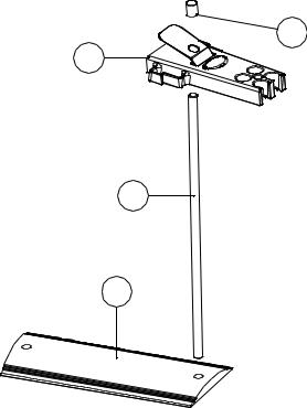
2.2 Installation
The Model 3510 is supplied ready to use. Connect the ATC (if required) and the pH electrode to the rear panel Temp and pH sockets.
The electrode stand requires minimal assembly (refer to the diagram below).
Fig. 2.2.1 Electrode Holder Assembly
4
1
2
3
2 |
351 050/REV B/09-06 |

2.3 Display
Fig. 2.3.1 – Display
1.Symbol – displayed during set-up of instrument parameters.
2.Primary display – 4½ digit. Provides direct readout in pH and millivolts of samples and standards.
3.Mode annunciators – shows selected measurement mode; pH, mV (Absolute and Relative).
4.Calibration point – shows 1, 2 or 3 point symbol depending on level of calibration selected by the user.
5.Buffer selection – indicates whether the instrument is using manually entered or automatic selection buffers. Will show which type of buffer is being used.
6.Endpoint symbol – this symbol is displayed when the pH changes by less than 0.005pH (0.2mV) over a five second period. Once an endpoint has been detected the reading must change by more than 0.005pH (0.2mV) to clear the endpoint symbol.
7.Secondary display – 6 digit display. Provides direct readout of automatic or manual temperature. Scrolls and displays selected parameter information in set-up mode.
8.Mode annunciators – indicates temperature in °C or °F and whether the measurements are manually or automatically temperature compensated.
9.Status display – 2½ digit. Provides information relating to electrode slope value, mV Eo value at calibration and memory result number.
10.Mode tags – Each mode tag is highlighted when selected; SETUP, MODE or RESULTS.
3 |
351 050/REV B/09-06 |

2.4 Keypad
2.4.1 Keypad
1. ESC |
used to switch the instrument on and to place into standby mode (only if power |
|
supply lead remains connected to the instrument). Also used to escape/exit a |
|
mode. |
2. CAL / CLR |
used to select and perform a calibration sequence. This key is also used to clear |
|
readings from Memory. Used to select Abs/Rel mV in mV mode. |
3. Print key |
used to initiate a print. |
4. Up Arrow |
used for adjustment during set up, to scroll results and to toggle between mV and |
|
pH modes. |
5. Down Arrow |
used for adjustment during set up, to scroll results and to toggle between mV and |
|
pH modes. |
6. Left Arrow |
used for adjustment during set up and to move between mode tags. |
7. Right Arrow |
used for adjustment during set up and to move between mode tags. |
8. STO |
used to accept an entered value in set-up mode and to instigate a stored |
|
reading. |
|
This key can also be used as a CAL key during calibration. |
4 |
351 050/REV B/09-06 |
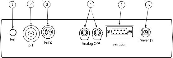
2.5 Inputs/Outputs
Fig. 2.5.1 – Rear panel layout
1. Ref Socket |
2mm pin socket. Connection socket for separate reference electrode. |
|
When performing measurements with some pH and ion selective |
|
electrodes a separate reference electrode is needed. |
2. pH Socket |
BNC type socket which allows combination pH or redox electrodes to be |
|
used. |
3. Temp Socket |
8 pin mini-DIN socket. This allows the Automatic Temperature |
|
Compensation (ATC) probe (027 500) to be connected. |
4. Analog Out |
2 x 4mm sockets. Analogue output (buffered electrode potential). |
5. Output Socket |
9 way socket for RS232 connection. |
6. Power In |
AC 9V I/P socket. 2.1 x 5.5mm socket allowing the power supply to be |
|
connected to the instrument. |
5 |
351 050/REV B/09-06 |
Section 3
Operation
3.1 Theory of pH Measurement
pH is a unit of measurement which defines the degree of acidity or alkalinity of a solution. It is usually measured on a scale of 0 to 14. The pH value quantifies the degree of hydrogen ion activity of an acid or a base in terms of hydrogen ion activity.
The internationally accepted symbol, pH, is derived from “p”, the mathematical symbol of the negative logarithm and “H”, the chemical symbol for Hydrogen. The pH value is the negative logarithm of Hydrogen ion activity as shown in the mathematical relationship pH= -log[H+].
The pH value of a substance is directly related to the ratio of the Hydrogen ion [H+] and the Hydroxyl ion [OH-] concentrations. If the concentration of H+ is greater than OH-, the material is acidic and has a pH value of less than 7. Conversely, if the concentration of OH- is greater than H+ the material is basic, with a pH value greater than 7. If the concentrations of H+ and OH- are equal the material is neutral with a pH value of 7.
It can, therefore, be seen that pH is a measurement of both acidity and alkalinity, even though by definition it is a selective measurement of hydrogen ion activity. The logarithmic relationship between hydrogen ion concentration and the pH unit means that a change of one pH unit represents a ten-fold change in hydrogen ion concentration.
3.2 pH Measurement
pH can be measured by using either pH papers/indicators or a pH meter, dependent on the level of accuracy required. pH papers or indicators change colour as the pH level varies. These can be used as a guide to the pH level, but can be limited in accuracy and difficult to interpret correctly in murky or coloured samples.
For greater accuracy the use of a high impedance pH meter is recommended, together with a pH measuring electrode and reference electrode.
Each component part of the measurement system can be described as follows:
a)the pH meter – is a high impedance amplifier used to accurately measure the minute electrode voltages produced. The pH meter will display the results directly in pH units on either an analogue or digital display. Voltages can also be read for special applications, ORP (Oxidation-Reduction Potential) measurements or with Ion Selective Electrodes.
b)the pH electrode – is a hydrogen ion sensitive glass bulb, with a millivolt output that varies with the changes in the relative hydrogen ion concentration inside and outside of the bulb. The pH electrode has very high internal resistance, making the voltage change with pH difficult to measure. The input impedance of the pH meter and leakage resistances are therefore important factors.
c)the reference electrode – these cells consist of an internal element, usually a silver/silver chloride wire, electrolyte (KCl) and a liquid junction. The liquid junction provides a leak path for the internal electrolyte to “weep” into the sample chamber and provide an electrical contact with the liquid to be measured. If the liquid junction is inefficient then measurement will be inaccurate. It is common for the reference electrode to be incorporated into the pH electrode. It is then called a combination electrode. The Model 3510 meter is supplied with a combination electrode.
6 |
351 050/REV B/09-06 |
|
The voltage developed by each individual pH electrode in the presence of a known hydrogen ion concentration is theoretically predictable, but in practise deviations from the theoretical value can be expected. These deviations will change slowly during the life of an electrode. It is therefore essential to routinely calibrate the system using solutions with a known and constant pH value. These solutions are called buffers.
3.3 Preparation of Buffer Solutions
Care must be taken in the preparation of all buffer solutions. The correct quantity of distilled or deionised water should be used when preparing the solutions. For accurate and repeatable results it is essential to follow the manufacturers instructions carefully.
3.4 Solution Temperature Values
The value of all buffer solutions varies with solution temperature. For accurate calibration of electrodes using buffer solutions, it is necessary to measure the temperature of the buffer solution being used. The unit should then be calibrated to the corrected pH value. Manufacturers of buffer powders and solutions will provide a table of values at varying temperatures for their buffers.
Note: |
Buffer solutions will contaminate with exposure to air and should be stored |
|
in airtight containers when not in use. Used solution should be discarded and |
|
not returned to the container as this will cause contamination. |
|
For best results fresh solutions should be prepared prior to calibration. |
7 |
351 050/REV B/09-06 |
 Loading...