


Model 3540
Combined pH & Conductivity Meter
Operating Manual
Safety
This is important information; please read carefully before installing or using this instrument.
1.The Model 3540 pH/Conductivity meter is only for operation by personnel who are trained and aware of the principles and applications involved in making electrochemical measurements. For further help and advice please contact your local distributor, e-mail sales@jenway.com or visit www.jenway.com
2.The Model 3540 pH/Conductivity meter is a sensitive electronic measuring instrument designed for use in a laboratory environment. Careful adherence to the installation instructions must be observed. If in doubt contact a relevant and competent authority for advice before proceeding.
3.In addition to observing the instructions detailed in the Operating Manual and Service Manual for this instrument all installation, operating and service personnel must be aware of, and employ, a safe system of work.
4.Voltage levels hazardous to life are present in this instrument, for personal safety only trained engineers aware of the risk and avoidance of electric shock should remove protective covers from the instrument.
5.This instrument is designed for minimal maintenance, which must be carried out carefully following the procedures detailed in this manual. All safety instructions in these procedures as well as those defined locally for the area or environment where the work is being carried out must be observed.
6.Other than for those items defined in the maintenance procedures herein there are no user serviceable items in this instrument. Removal of covers and attempted adjustment or service by unqualified personnel will invalidate any warranty and incur additional charges for repair.
7.Reference should always be made to the Health and Safety Data for any chemicals or reagents used. All available information, advice and warnings on the handling, storage, use and disposal of such must be carefully observed. When not available this data must be requested from the supplier before proceeding in any way.
8.It is important that good laboratory practice is observed when handling samples, chemicals, reagents and ancillary equipment in order to carry out measurement and analysis with this instrument. Suitable safety and personal protective equipment must be used at all times.
9.If it is suspected that safety protection has been impaired in any way, the instrument must be made inoperative and secured against any intended operation. The fault condition must be reported to the appropriate servicing authority. In all such reports the model number and serial number of the instrument must be quoted.
Contents:
Section 1 |
Introduction |
|
|
Instrument description |
1.1 |
|
Display & controls |
1.2 |
|
Outputs |
1.3 |
|
Electrode Selection |
1.4 |
|
Good practice guidelines - pH |
1.5 |
|
Good Practice Guidelines – Conductivity |
1.6 |
Section 2 |
Getting Started |
|
|
Unpacking |
2.1 |
|
Installation |
2.2 |
Section 3 |
Set Up - General |
|
|
Instrument Set Up |
3.1 |
|
GLP Set Up |
3.2 |
|
Data Logging Set Up |
3.3 |
|
Time/Date Set Up |
3.4 |
Section 4 |
Conductivity Set Up |
|
|
Conductivity Calibration Set Up |
4.1 |
|
Conductivity Alarms Set Up |
4.2 |
|
Conductivity End Point Set Up |
4.3 |
|
Conductivity ATC/MTC Set Up |
4.4 |
Section 5 |
pH Set Up |
|
|
pH resolution |
5.1 |
|
mV Resolution |
5.2 |
|
pH Calibration Set Up |
5.3 |
|
pH Alarms Set Up |
5.4 |
|
pH End Point Set Up |
5.5 |
|
pH ATC/MTC Set Up |
5.6 |
Section 6 |
Calibration |
|
|
pH Calibration |
6.1 |
|
Conductivity Calibration |
6.2 |
Section 7 |
Measurement |
|
|
pH/Conductivity Measurement |
7.1 |
|
mV Measurement |
7.2 |
|
TDS Measurement |
7.4 |
|
Resistivity Measurement |
7.5 |
|
Salinity Measurement |
7.6 |
Section 8 |
Maintenance & Troubleshooting |
|
|
General and routine maintenance |
8.1 |
|
Cleaning/Re-conditioning of Glass Electrodes |
8.2 |
|
Error codes and troubleshooting - pH |
8.3 |
|
Error codes and troubleshooting – Conductivity |
8.4 |
|
Functional Check – pH |
8.5 |
|
Functional Check – Conductivity |
8.6 |
|
Functional Check – Temperature |
8.7 |
|
Functional Reset |
8.8 |
Section 9 |
Accessories and Spares |
|
|
Optional accessories |
9.1 |
|
Spares |
9.2 |
Section 10 |
Specification & Data |
|
|
Technical specification |
10.1 |
|
Analogue output |
10.2 |
|
RS232 serial interface |
10.3 |
|
Keypad emulation |
10.4 |
|
Printing |
10.5 |
|
Alarm Outputs |
10.6 |
Addendum |
Buffer/Standard Vs Temperature Tables |
|
|
Jenway |
Ad.1 |
|
NIST |
Ad.2 |
|
DIN |
Ad.3 |
|
JIS |
Ad.4 |
|
Conductivity |
Ad.5 |

Section 1
Introduction
1.1Instrument Description
The model 3540 pH/conductivity meter is a dual channel, dual readout instrument that displays both pH and conductivity values simultaneously. The model 3540 is designed to show both readings in real time and eliminates cross channel interference, as well as the need to either switch manually or automatically between measurements. The design also enables both dual channel and independent single channel operation. Predictive Selection simplifies operation by taking you directly to the screen relevant to your current task.
The unit enables pH measurements to be made with a 1, 2 or 3 decimal place resolution against a 1, 2 or 3 point calibration. Automatic calibration can be carried out against standard NIST, DIN, JIS or Jenway buffers. Alternative values can be entered and stored for semiautomatic operation. The pH channel can also display Absolute and Relative mV values to 0.1mV resolution, enabling Redox/ORP and simple ISE measurement to be made.
The conductivity channel is auto ranging from 0.01µS up to 19.99S (with x10 probe). This eliminates the need for manual range selection across this wide measuring range. Reference temperatures of 18, 20 and 25°C are offered, along with a temperature coefficient that can be varied from 0% (off) up to 4% per degree Celsius. Three calibration methods can be employed: automatic recognition of common conductivity calibration standards, semiautomatic calibration against manually entered values within the measuring range or, a simple calibration against the quoted cell constant (K factor) for the probe being used. The conductivity channel can also be set to readout in Resistivity, Salinity or TDS values.
Configuring the instrument to your ideal options is easily achieved using the clear and simple set up menus. Once entered, these options can be locked against inadvertent change by entering a Supervisor Security Code.
Access to Set Up menus blocked by incorrect security code entry
GLP functions include user and sample batch identity, calibration reminder, security set up and date/time stamping of results.
Data logging and alarm functions are also included. Results can be stored to the internal memory (250 pH and 250 conductivity readings) or output via the RS232 serial port to a printer or computer. This storage or output function can be triggered manually by pressing the Store key, or be set on a timed basis. It can also be triggered when a sample reading reaches stability, or on the activation and reset of any alarm level.
The model 3540 has a high specification and a comprehensive range of features and functions. Please read through this manual before installation. Refer to it frequently to ensure you are making full use of all the functions.
1.2Display and Controls
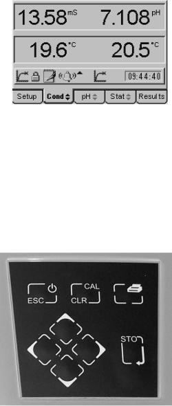
The model 3540 has a back lit 1/8 VGA dot matrix LCD. In normal measurement mode the left-hand side displays the conductivity value and the right hand side the pH value. Both channels have their own temperature/ATC input displayed below the measured value, making them fully independent. The display includes a number of icons and prompts used to inform and indicate to the user the instrument status and measurement conditions. The operating system is based around five separate screens, each of which can be displayed by moving the cursor along the tabbed menu bar at the bottom of the display.
Typical display showing independent temperature/ATC measurement and a range of prompting icons
The simple keypad controls all the functions of the instrument. The ON/OFF key operates as an escape [ESC] key at sub-menu levels, each press returning to the next highest level until the main measurement screen is reached, where a further press will switch the instrument off.
Pressing the CAL key initiates the calibration sequence for the channel highlighted on the tabbed menu bar. The calibration sequence will be based on the options selected in the relevant calibration set up menu. When recalling results, with the Results tab highlighted, the CAL key functions as a Clear [CLR] key, returning the function defined for the Clear key in the data logging set up menu.
Simple keypad enables easy operation
The Print key outputs the currently displayed measurement, stored results or statistics screen to the RS232 serial port, where it can be printed on the optional serial printer. An option to print the measurement displayed on one or both channels can be selected in the Printer Set Up menu.

The Enter key confirms selections as they are made in the set up menus. With the measurement screen displayed it acts as the Store [STO] key and stores the current readings in the internal memory. Up to 250 pH and conductivity readings can be stored. The action taken when the memory is full can be selected in the data logging set up menu.
The four Cursor keys enable easy navigation through the set up menus, as well as selection of the required screen on the tabbed menu bar. The Up or Down Cursor keys are also used to select alternative measuring modes from the highlighted channel on the main measurement screen.
1.3Outputs
The Model 3540 has RS232 serial, analogue and alarm outputs.
The serial output includes data for both channels as displayed on the measurement screens. The analogue output can be switched between the pH and conductivity measurement by highlighting the required channel on the tabbed menu bar. The alarm function can be set independently for each channel with high and low options for every mode of operation. The ‘open collector’ output can be used directly for low current switching, or via relays for other control functions.
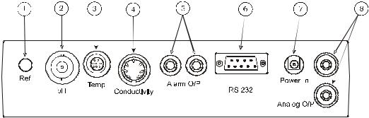
Rear Panel showing output connectors
1.4Electrode Selection
The performance of any electrochemistry measurement system is highly dependent on the selection of appropriate sensing electrodes suitable for the sample being measured. Jenway offer a comprehensive range of pH and conductivity electrodes with versions suitable for most applications and sample types. For help or advice on choosing the best electrodes for your application contact sales@jenway.com or visit www.jenway.com.
1.5Good Practice Guidelines – pH
1.Selection of the correct electrode for your application is the most important factor in achieving good performance and extended electrode life. The use of Application Specific electrodes is recommended for all but the simplest sample matrix and measurement conditions. Please contact Jenway if you require further help or advice on electrode suitability and application support.
2.For best results follow Good Laboratory Practice (GLP) at all times. Ensure regular calibration using buffer solutions with values that bracket the expected sample pH levels. Always record the sample/buffer temperature with its corresponding pH value.
3.Always ensure that all buffer solutions and reagents used are within their expiry dates. Never return unused solutions to the bottle, nor insert the electrode directly into the bottle. Always replace caps on their respective bottles immediately after use.
4.Ensure that the correct buffer set is selected (e.g. NIST, DIN, JIS, etc), or that the temperature corrected value of the buffer is used for calibration, NOT the nominal value.
5.Recording the electrode Offset and Slope values after each calibration will enable electrode condition to be monitored and the most effective calibration and maintenance procedures to be implemented.
6.Ensure BOTH pH and temperature values are stable before recording results or confirming calibration. Where sample and/or buffer temperature vary, or are significantly different from ambient, greater accuracy and faster analysis can be achieved by keeping buffers, samples, rinse solution, electrode and ATC probe in a water bath or other temperature controlled environment.
7.Ensure the electrode is rinsed with deionised water between each sample and calibration buffer.
DO NOT touch the sensitive pH glass membrane or reference junction. Excess liquid may be removed by gentle blotting with a soft tissue.
DO NOT rub the electrode as this may cause an electrostatic charge.
8.For Refillable Electrodes:
Ensure that the electrode’s outer chamber is at least two thirds full. Always use the correct fill solution for the electrode. Use of the wrong solution WILL cause irreversible damage. Always open the fill port during use.
9.DO NOT immerse any electrode below the level of the internal fill solution (except for those designated as submersible).
10.Always use electrodes within their specified temperature range. Degradation of electrodes used above their operating temperature is rapid and irreversible.
11.Always use and store the electrode in an upright vertical position. Ensure no air bubbles are trapped in the internal solutions. Air bubbles may be removed by gently shaking the electrode in a downward direction.
12.Regular electrode cleaning and maintenance will improve performance and extend working life. Use only cleaning solutions and procedures detailed in the instructions supplied with the electrode. Others may damage the electrode and degrade performance.
13.Storage conditions can have a greater impact on electrode performance and operational life than sample type. Store only as directed in the instructions supplied with the electrode.
For general guidance:
Refillable Electrodes
After Use Rinse thoroughly with deionised water. Leave the fill port open and immerse in a beaker of 4 pH buffer solution. Ensure both glass bulb and reference junction are covered.
Overnight Rinse thoroughly with deionised water. Leave the fill port open and immerse in a small beaker containing electrode storage solution. Ensure both glass bulb and reference junction are covered.
Short Term Clean according to instructions and rinse thoroughly with deionised water. Close the fill port and re-fit the soaking bottle or wetting cap filled with storage solution.
Long Term Clean according to instructions and rinse thoroughly with deionised water. Top up the fill solution and close the fill port. Re-fit the soaking bottle or wetting cap filled with storage solution. Return to the original packaging and store away from direct sunlight in a vertical position and within the electrodes specified temperature range.
Sealed Non Fillable Electrodes
After Use/ Rinse thoroughly with deionised water and immerse in a small Overnight beaker containing electrode storage solution. Ensure both glass bulb
and reference junction are covered.
Short Term Clean according to instructions and rinse thoroughly with deionised water. Re-fit the soaking bottle or wetting cap filled with electrode storage solution.
Long Term Clean according to instructions and rinse thoroughly with deionised water. Re-fit the soaking bottle or wetting cap filled with electrode storage solution. Return to the original packaging and store away from direct sunlight in a vertical position within the electrodes specified temperature range.
1.6Good Practice Guidelines – Conductivity
1.After using the conductivity probe ensure it is rinsed thoroughly, or cleaned then rinsed if used in adhering samples. Between samples and for short-term storage the probe should be stored with the measuring plates immersed in a beaker of deionised water. This should be replaced regularly to ensure no contamination or growth occurs.
For longer-term storage conductivity probes may be stored dry, but will need soaking in deionised water for at least 1 hour before re-use.
2.Conductivity measurements are temperature dependent, for greater accuracy and for measurement comparisons sample temperature must be recorded, along with the reference temperature and temperature coefficient used.
3.Calibration against quoted cell constants (K factors) should only be carried out where these are known and are reliable. If in doubt, good quality calibration standards should be used for calibration and/or re-calculating the cell constant (K factor).
4.For greatest accuracy in laboratory measurements, and to conform to USP standards, temperature compensation should be switched off (set temperature coefficient to zero). In addition, all samples and calibration standards should be kept at the reference temperature by use of a water bath or other temperature controlled environment.
5.When measuring samples at a temperature that differs significantly from ambient, sufficient time must be allowed for the internal temperature sensor to respond to this change.
6.The presence of particulate matter in the sample can lead to unstable and nonreproducible results. If necessary filter, or allow the particles to settle prior to measurement.
7.Ensure no air bubbles are trapped in the measuring cell. Gentle agitation of the cell should ensure that bubbles are purged.
8.The entire plate area must be immersed in the solution under test. The slots in the side of the sensor should be below the surface. Ensure the probe is rinsed with deionised water between each test. A further ‘sample rinse’ may be necessary for low conductivity measurements.
9.The measurement of low conductivity samples must be performed with great care to avoid contamination. At the lowest levels the leeching of substances from the sample container or absorption of gasses from the atmosphere may affect readings.
10.It is advisable to clean the sensor if contamination is evident. This should be approached in a progressive manner, beginning with deionised water and progressing to other solvents or a soft airbrush if the deposits persist. The plates can be damaged and should not come into contact with anything that is likely to abrade their surface.
11.The temperature coefficient is very dependent on the solution being measured and its concentration level. The effect of temperature change on conductivity can be very significant, and if the temperature coefficient is not know it is wise to measure all samples at the reference temperature.
12.The TDS mode displays results that have been calculated from the conductivity measurement and assumes some knowledge of the electrolyte balance of the sample. The EC ratio allows selection of a factor suitable for the solution under test. Most instruments that do not offer this option use a default value of 0.6.
Section 2
Getting Started
2.1Unpacking
Remove the 3540 from the packaging and ensure the following items are included:
1.Model 3540 pH/Conductivity Meter
2.Glass bodied combination pH electrode (924 005)
3.Epoxy bodied Conductivity Cell K=1 (027 013)
4.ATC probe (027 500)
5.Electrode Holder
6.4, 7 & 10 pH buffer sachets
7.BNC shorting plug (009 146)
8.Power supply (as specified at the time of ordering)
9.Condensed operating instructions (354 051)
10.Operating Manual (354 050)
Any shortages or damage must be reported to your local distributor or the manufacturer as soon as possible.
Typical Items supplied
Keep all packing materials in case the unit has to be re-shipped at a later date. It is important that when re-packing the instrument it is first placed in a sealed polythene bag.
2.2Installation
2.21Location
The Model 3540 must be positioned within 1.5 meters of an electric supply socket.
In ideal circumstances the installation environment will be clean, dry and dust free. Where conditions are less than ideal, maintenance and cleaning must be carried out regularly and additional protection offered, where possible. The optional dust cover should always be fitted when the unit is not being used or is stored for short periods.
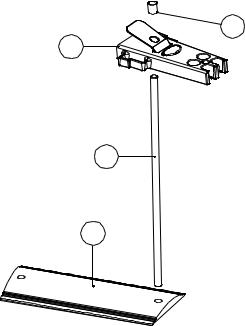
2.22Electrode Holder Assembly
The electrode holder requires minimal assembly (refer to the diagram below).
4
1
2
3
Decide on which side of the instrument you require the electrode stand to be positioned. Align the base plate with the shorter edge to the front of the instrument, so that the tapered sides match the taper on the instrument.
Screw the rod into the base on the side required. If gripping the rod is difficult an Allen key or small screwdriver inserted in the 4mm hole at the bottom of the rod enables it to be tightened further.
Remove the rubber top cap and slide the electrode down the rod while squeezing the sprung retainer. Replace the rubber top cap.
Fit the electrodes and ATC probe into the holder, use the side clips to keep the cables tidy.
Adjust the height and rotation of the electrode holder to suit your work station and sample containers as necessary.
2.2.3Power Supply, probes and accessory connection
|
|
|
|
|
|
|
|
|
|
|
|
|
|
|
|
|
|
|
|
|
|
|
|
|
|
|
|
|
|
|
|
|
|
|
|
|
|
|
|
|
|
|
|
|
|
|
|
|
|
Rear Panel showing Input and Output Connectors |
|||||
1. |
Ref Socket |
2mm-pin type socket. Connection socket for separate reference |
|||||
|
|
electrode. When performing measurements with some pH and |
|||||
|
|
ion selective electrodes a separate reference electrode is |
|||||
|
|
needed. |
|||||
2. pH Socket |
BNC type socket which allows combination pH or redox |
||||||
|
|
electrodes to be used. |
|||||
3. |
Temp Socket |
8-pin mini-DIN socket. This allows the supplied Automatic |
|||||
|
|
Temperature Compensation (ATC) probe to be connected. |
|||||
4. |
Conductivity Socket |
7-pin DIN socket. This allows the conductivity cell to be |
|||||
|
|
connected. |
|||||
5. |
Alarm Output |
2x4mm sockets. Open collector alarm outputs. |
|||||
|
|
Red for High / Black for Low. |
|||||
6. |
Printer Socket |
9-way socket for RS232 serial communication, for serial printer, |
|||||
|
|
PC connection or other data communication. |
|||||
7. |
Power In |
AC 9V I/P socket. 2.1 x 5.5mm socket allowing the power |
|||||
|
|
supply to be connected to the instrument. |
|||||
8. |
Analog O/P |
Two 4mm sockets. Analogue output for selected channel. |
|||||
Section 2.24 Installation Verification
1.Connect the power supply, conductivity cell and ATC probe to the rear panel, as described in the previous section. (Do not immerse the probes in solution at this stage).
2.Connect the BNC shorting plug (009 146) to the pH input in place of the pH electrode.
3.Switch on the power at the mains supply socket, if necessary, then press the power on/off key on the instrument.
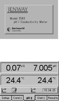
4.The 3540 start up screen is shown for a few seconds…
Start Up screen shown during internal self checking
…followed by the main measurement screen with either the pH or conductivity tab highlighted (depending on which was active when power was switched off).
Main measurement screen with pH tab highlighted
5.The pH reading should be close to 7.00(0). The actual value will depend on the last calibration and the resolution that was selected in the pH set up menu.
6.The conductivity reading should be a low µS value. This will also depend on the last calibration.
7.With the ATC and conductivity probes in the same environment, the temperature readings should equilibrate to within ±0.5°C of the ambient temperature.
8.Remove the BNC shorting plug from the pH input and reconnect the pH electrode. Remove the wetting cap or soaking bottle from the sensing end of the pH electrode.
9.Soak the pH electrode in 4 pH buffer solution and the conductivity probe in deionised water for at least 30 minutes before carrying out calibration and sample measurement.
10.This procedure should be followed if the instrument is re-installed at a new location, or when put back into use after a period of storage. For routine power-on and operation see Section 4.
Section 3
Set Up - General
3.00General Set Up
The general set up options include instrument wide functions that are relevant for both pH and conductivity channels. Functions that can be set in these menus are language, display brightness, GLP options, data logging options, clock, security and printer set up. Adjustments made to these settings are stored in non-volatile memory so will not need to be re-entered unless further changes are required. They will also be retained regardless of the power connection to the instrument.
3.01Connect the power supply as described in section 2.2.3. It is not necessary to connect the probes for the set-up procedures.
3.02Switch on the power at the supply socket; then press the power on/off key on the instrument.
3.03The 3540 start up screen is shown for a few seconds followed by the main measurement screen with either the pH or conductivity tab highlighted (depending on which was active when power was switched off).
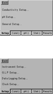
3.04Press the right or left arrow keys [ ] to highlight the Set Up tab on the menu bar at the bottom of the screen. This will open the main Set Up page.
Main Set Up screen
3.05Press the up or down arrow keys [  ] to move the highlight over the General Set Up… option. Press the enter key [
  ] to open the General Set Up page.
General Set Up Screen
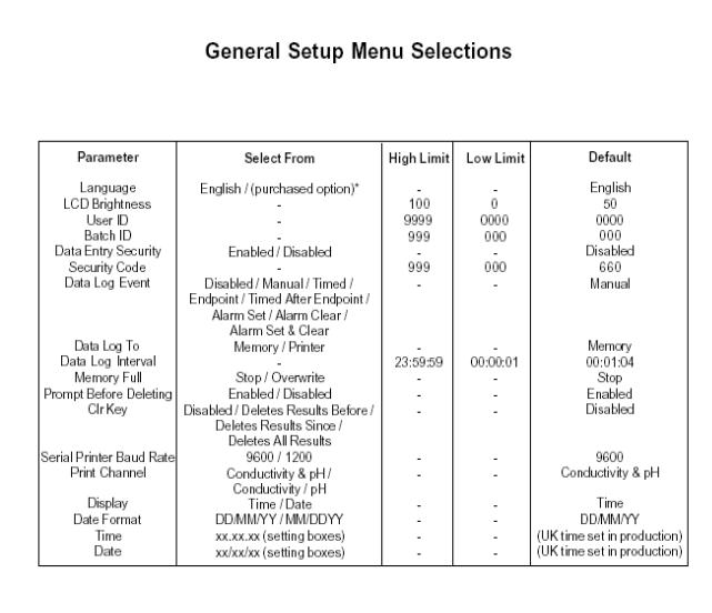
Use the General Set Up flow diagram and General Set Up menu selections on the following pages to identify the settings that you wish to adjust from their default values. Then refer to the following paragraphs for further guidance on making these adjustments.

3.10Instrument Set Up
The Instrument Set Up menu contains options for selecting the operating language and adjusting the brightness of the display to compensate for adverse lighting situations.
Access the Instrument Set Up menu by carrying out paragraphs 3.01 to 3.05, then use the up or down arrow keys [ ] to move the highlight over the Instrument Set Up option then press the Enter key [
 ]. The Instrument Set Up screen below will be displayed…
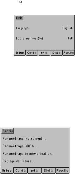
Instrument Set Up screen
3.11Language Options
The model 3540 is supplied with two operating languages as standard. English is the default language with the alternative being selected at the time of purchase from French, German, Italian or Spanish.
To change the language on the display press the down arrow to highlight the Language option in the Instrument Set Up screen, then press the Enter key. The highlight will move across to the default language of ‘English’ or the alternative if this has been previously changed. Use the up or down arrow keys to toggle between the two language options and press the Enter key to accept your preferred alternative and return the highlight to the left-hand side of the menu. Use the Escape key to return to other menu levels or continue with setting the LCD brightness as below.
General Set Up screen displayed in French
3.12LCD Brightness %
The display brightness is optimised for a wide range of lighting conditions, should installation in an area with unusual lighting requirements be necessary the display brightness can be adjusted to ensure clarity is maintained. The value displayed for the brightness is a percentage of the maximum, with 100% being the brightest and 0% being the darkest. At both extremes the contrast is such that the display can still be read. The default value of 50% should give optimum brightness in normal conditions.

To change the brightness of the display press the down arrow to highlight the LCD Brightness (%) option in the Instrument Set Up screen, then press the Enter key. The highlight will move across to the percentage previously set (or the default value of 050). A data entry box will appear in the centre of the screen. The box around the least significant digit will be flashing to indicate that this digit can be changed by pressing the up or down arrow keys.
Data entry box for adjusting display brightness
When this is set to the desired value the right or left arrow keys can be used to move the flashing highlight to the other digits which in turn can be adjusted to the desired levels with the up or down arrow keys. When all digits are set to the desired levels press the Enter key to confirm the setting and return the highlight to the left-hand side of the menu. Use the Escape key to return to other menu levels or continue with setting the Language as above.
Should a value above the maximum (100%) be selected, then when the Enter key is
Warning that value entered is outside limits
pressed a warning message is displayed and the setting automatically corrected to the maximum level permitted.
3.20GLP Set Up
The GLP Set Up menu contains options for entering a User ID (4-digit code), a Batch ID (3-digit code) and the Security Code options. GLP functions relating to Calibration periods and calibration performance data are included in the Calibration Set Up menus for each channel individually.
Access the GLP Set Up menu by carrying out paragraphs 3.01 to 3.05, then use the up or down arrow keys [  ] to move the highlight over the GLP Set Up option then press the Enter key [
 ]. The GLP Set Up screen below will be displayed…
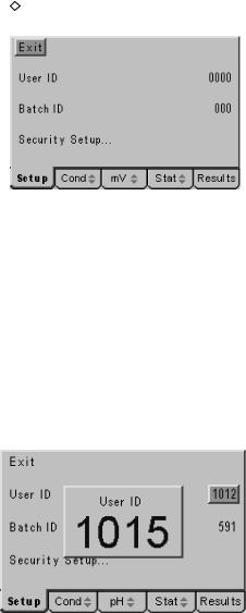
GLP Set Up screen
3.21User ID
A four digit numeric code can be entered to identify individual users of the instrument. This code is printed in the header of any print out generated and included with data transmitted to a PC.
To change or set a User ID, press the down arrow to highlight the User ID option in the GLP Set Up screen, then press the Enter key. The highlight will move across to the User ID previously set (or the default value of 0000). A data entry box will appear in the centre of the screen. The box around the least significant digit will be flashing to indicate that this digit can be changed by pressing the up or down arrow keys. When this is set to the desired value the right or left arrow keys can be used to move the flashing highlight to the other digits which in turn can be adjusted to the desired levels with the up or down arrow keys. When all digits are set to the desired levels press the
Data entry box for setting User ID
Enter key to confirm the setting and return the highlight to the left-hand side of the menu. Use the Escape key to return to other menu levels or continue with setting the Batch ID or Security Set Up as below.
3.22Batch ID
A four digit numeric code can be entered to identify specific sample batches. This code is stored with the results in internal memory, printed with all results and included with data transmitted to a PC.
To change or set a Batch ID, press the down arrow to highlight the Batch ID option in the GLP Set Up screen, then press the Enter key. The highlight will move across to the Batch ID previously set (or the default value of 000). A data entry box will appear in the centre of the screen. The box around the least significant digit will be flashing to indicate that this digit can be changed by pressing the up or down arrow keys. When this is set to the desired value the right or left arrow keys can be used to move the flashing highlight to the other digits which in turn can be adjusted to the desired levels with the up or down arrow keys.
Data entry box for setting Batch ID
When all digits are set to the desired levels press the Enter key to confirm the setting and return the highlight to the left-hand side of the menu. Use the Escape key to return to other menu levels or continue with setting the Security Set Up as follows.
3.23Security Set Up
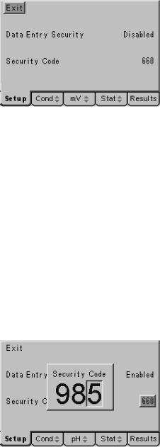
The Security Set Up has a sub-menu with options to enable or disable the security code. With it disabled there is free access to all the set up menus, with it enabled no set up menus can be accessed without the entry of the security code. When the security code is enabled a padlock icon appears in the status bar on the display and when the Set Up tab is highlighted a data entry box is displayed for entry of the security code before any further access is allowed. The sub-menu also enables the security code to be changed by a supervisor as necessary.
Padlock icon indicates set up is secure |
Security code required to access Set Up menus |
To enter the Security Set Up sub-menu, press the down arrow to highlight Security Set Up… in the GLP Set Up screen, then press the Enter key.
The following sub-menu is displayed.
Security Set Up sub-menu
3.23Data Entry Security
To enable or disable data entry security (as described above) press the down arrow key in the Security Set Up sub-menu to highlight the Data Entry Security option in the menu. Then press the Enter key to move the highlight to the current selection. Press the up or down key to toggle between the Disabled and Enabled options. Press the Enter key to confirm your choice when it is highlighted and return to the left-hand side of the menu. Use the Escape key to return to other menu levels or continue with setting the Security Code as below.
3.24Security Code
To change the security code from the default value or to set a new security code press the down arrow to highlight Security Code in the Security Set Up sub-menu. Press the Enter key to move the highlight to the current selection. A data entry box will appear in the centre of the screen. The box around the least significant digit will be flashing to indicate that this digit can be changed by pressing the up or down arrow keys. When this is set to the desired value the right or left arrow keys can be used to move the flashing highlight to the other digits, which in turn can be adjusted to the desired levels with the up or down arrow keys.
Data entry box for setting a new security code
When all digits are set to the desired levels press the Enter key to confirm the setting and return the highlight to the left-hand side of the menu. Use the Escape key to return to other menu levels or the main measurement screen.
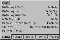
3.30Data Logging Set Up
The data logging set up menu enables all the functions of the data logger to be set, including the event trigger, logging period and data destination. The function of the Clear [CLR] key on stored data can also be set, there is also a sub-menu for the Printer options.
Access the Data Logging Set Up menu by carrying out paragraphs 3.01 to 3.05, then
use the up or down arrow keys [ ] to move the highlight over the Data Logging Set Up option, then press the Enter key [
 ]. The Data Logging Set Up screen below will be displayed…
Data Logging Set Up screen
3.31Data Log Event
The data log event is the occurrence that triggers data to be sent to either internal memory or the printer/computer via the serial port. There are eight options, making this a useful and comprehensive function.
Disabled: Effectively switches data logging functions off.
Manual: Data logging is triggered from a press of the Store [STO] key only. Timed Interval: Data logging is triggered on a period set by the Data Log interval. Endpoint Detection: Data logging is triggered when the sample measurement
reaches stability – this can be used to enhance productivity when measuring batches of samples by having the results automatically printed or stored without the operator having to even press a button.
Timed after Endpoint: Data logging is triggered at the entered data log interval but only after the endpoint detection – this enables data from reactions or slowly changing sample streams to be logged with more control.
Alarm Set: Data logging is triggered when one of the alarm conditions is reached. This is useful for tracking time/date of problems occurring.
Alarm Clear: Data logging is triggered when one of the alarm conditions is cleared. This is useful for tracking time and date when problems are cleared.
Alarm Set & Clear: Data logging is triggered when one of the alarm conditions is set and also when they are cleared. This gives useful data for analysing problems or control functions.

To change the data logging trigger press the down arrow to highlight Data Log Event in the Data Logging Set Up screen, then press the Enter key. The highlight will move across to the default setting of ‘Manual’ or an alternative from the above if this has previously been changed. Use the up or down arrow keys to review the options and
Use the up or down keys to select required Data Log Event
press the Enter key to accept your preferred setting when this is highlighted on the display. Use the Escape key to return to other menu levels or continue with setting the other data logging options as follows.
3.32Data Log To
Data logged on the event selected from the above can either be stored in internal memory or sent via the serial port to a printer or PC. The Data Log To option allows selection of either the internal memory or printer for this function.
To change the destination for logged data press the down arrow to highlight Data Log To in the Data Logging Set Up screen, then press the Enter key. The highlight will move across to the default setting of ‘Memory’ or ‘Printer’ if this has previously been changed.
Select destination for logged data
Use the up or down arrow keys to toggle between the options and press the Enter key to accept your preferred setting when this is highlighted on the display. Use the Escape key to return to other menu levels or continue with setting the other data logging options as below.
3.33Data Log Interval
The data log interval is effective when timed data logging is selected and also sets the time delay after the endpoint if this option is selected. Time periods from 1 second to 24 hours (1 result stored per day) can be set.

To change the data log interval from the default value or to set a new interval press the down arrow to highlight Data Log Interval in the Data Logging Set Up screen. Press the Enter key to move the highlight to the current selection. A data entry box will appear in the centre of the screen. The box consists of three pairs of digits separated by colons, from the left these represent hours, minutes and seconds. The box around the least significant of the seconds’ digits will be flashing to indicate that this digit can be changed by pressing the up or down arrow keys. When this is set to the desired value the right or left arrow keys can be used to move the flashing highlight to the other digits, which in turn can be adjusted to the desired levels with the up or down arrow keys.
Set Data Log Interval by adjusting each digit in turn
When all digits are set to give the desired time period press the Enter key to confirm the setting and return the highlight to the left-hand side of the menu. Use the Escape key to return to other menu levels or continue with setting the other data logging options as follows.
3.34Memory Full
The internal memory can store up to 250 pH and conductivity readings. The ‘Memory Full’ option offers two alternative actions when this limit is reached; Stop, which stops further logging and switches off the data pad icon on the display, or Overwrite, which starts overwriting the oldest records with the newly stored data.
To change the action when the memory is full press the down arrow to highlight Memory Full in the Data Logging Set Up screen, then press the Enter key. The highlight will move across to the default setting of ‘Stop’ or ‘Overwrite’ if this has previously been changed. Use the up or down arrow keys to toggle between the
Select the required action if the memory is full
options and press the Enter key to accept your preferred setting when this is highlighted on the display. Use the Escape key to return to other menu levels or continue with setting the other data logging options as below.
 Loading...