

Page 1
VM9022HDN
Installation and Operation Manual
video
280
Watts Peak
60wx4|40wx1
Page 2

Page 3

CONTENTS
Thank you for choosing a Jensen product. We hope you will find the instructions in this owner’s
manual clear and easy to follow. If you take a few minutes to look through it, you’ll learn how to
use all the features of your new Jensen VM9022HDN Mobile Multimedia Receiver for
maximum enjoyment.
VM9022HDN
Preparation............................................................................................................................ 1
Installation ............................................................................................................................. 5
Anti-Theft Feature ................................................................................................................. 7
Controls and Indicators ......................................................................................................... 8
Remote Control ................................................................................................................... 10
Using the TFT Monitor ........................................................................................................ 13
Operating Instructions ......................................................................................................... 14
Multi-ZONE Operation......................................................................................................... 16
Setup Menu......................................................................................................................... 17
Tuner Operation .................................................................................................................. 20
Satellite Radio Operation .................................................................................................... 22
DVD/VCD Video Operation ................................................................................................. 24
DVD/CD Audio Operation ................................................................................................... 27
MP3/WMA Operation .......................................................................................................... 28
iPod Operation .................................................................................................................... 30
Bluetooth Operation ............................................................................................................ 32
Troubleshooting .................................................................................................................. 35
Specifications ...................................................................................................................... 38
Navigation Module
Introduction ......................................................................................................................... 39
Safety Information ............................................................................................................... 40
Getting Started .................................................................................................................... 41
Main Navigation Features ................................................................................................... 42
Choosing and Finding Locations......................................................................................... 44
Navigating ........................................................................................................................... 48
Planning a Route................................................................................................................. 49
Managing your Address Book ............................................................................................. 50
Settings Menu ..................................................................................................................... 52
Navigation Module Troubleshooting.................................................................................... 55
i
Page 4

ii
Page 5

VM9022HDN
PREPARATION
Congratulations on your purchase of the Jensen
VM9022HDN Mobile Multimedia Receiver.
It’s a good idea to read all of the instructions before beginning
the installation. We recommend having your Jensen
VM9022HDN installed by a reputable installation shop.
Features
DVD
• Aspect Ratio – Cinema and Normal
• Fast Forward / Reverse – 2X, 4X, 6X and 8X
• Play, Pause, Stop, Next Chapter and Previous Chapter
• ESP – 2MB Buffer
CD / MP3 / WMA
• ID3 Tag Compatible
• Directory Search (MP3 / WMA Only)
• Direct Track Access via Remote control
• Burn up to 1500 MP3 and WMA Files onto a DVD+R /
RW
• Audible Forward / Reverse Track Search
• Random, Repeat and Intro
• Play, Pause, Stop, Next Track and Previous Track
• ESP – 2MB Buffer
Tuner
• HD Radio Tuner*
• USA / Europe Frequency Spacing
• 24 Station Presets (18 FM / 6 AM)
• Auto Stereo / Mono
• Auto Store
• RDS – Radio Data System
Satellite Radio Ready
• Compatible with XM Tuners (Sold Separately)
• Requires XMDJEN100 or JXMC cables for XMD1000
only (Sold Separately)
• Satellite Channel Name, Artist, Song and Categories
displayed on TFT Screen
iPod
• jLinkDirect - High Speed Direct Connect Interface to
Access iPod Playlists, Artists, Albums, Songs, Photos**
and Video**. (** Requires Gen 5.5 or earlier Photo or
Video iPod. iPhone, iPod Touch, iPod Classic, and iPod
Nano with Video will only play music files.)
• Power Management Charges iPod while Connected
• Requires jLinkCable iPod Interface Cable (included)
MediaLink
• Under Dash Interface Allows Portable Media Devices to
• MediaLink
Chassis
• 2.0 DIN (Import / ISO-DIN Mountable)
• Motorized Swing-Down LCD Screen
• 6.5" TFT Active Matrix LCD with Anti-Glare Coating
• Screen Tilt / Angle Adjustment
• Heat Management System - Forced Air-Cooling to Keep
General
• Bluetooth – Bluetooth hands-free profile for safety /
• Built-in Navigation System
• 38-Key Infrared Remote Control with 5-way Joystick
• Two Composite Video Outputs for Additional Screens
• Compatible with MZ7-TFT Rear Seat Monitors with
• Two Audio /Video Auxiliary Inputs
• 200-Ohm Preamp Line Output – All Audio Channels
• 4VRMS Line Output – All Channels
• Rotary Encoder Audio Control
• Seven-Band EQ with Eight Preset EQ Curves
• Spectrum Analyzer
• Front, Rear, Center and Subwoofer Line Output
• Built-In Integrated Center Channel Amplifier
• Subwoofer Crossover and Phase Control
• Dolby Digital / Pro-Logic ll
• Programmable Volume Control
• Rear Camera Input (Normal and Mirror Image View)
• 5-Way Joystick
• SWC Interface – Compatible with PAC adapter SWI-PS
*HD Radio™ Technology Manufactured Under License From
iBiquity Digital Corporation. U.S. and Foreign Patents. HD
Radio™ and the HD and HD Radio logos are proprietary
trademarks of iBiquity Digital Corporation.
4
be Connected
• USB – Supports Flash Memory and Hard Drives with
• LinkDirect iPod Connectivity
• 3.5mm Audio Only Input
• RCA Audio /Video Input
the Chip-Sets Operating at Nominal Temperatures
convenience and A2DP profile for streaming music from
a PDA / PMP
Touch Screen Interface
(40 Watts X 1)
Steering Wheel Control Interface, sold separately
4
Includes the Following Connectivity:
Audio Files
1
Page 6
VM9022HDN
Optional Equipment
• Rear Camera
The VM9022HDN is "camera ready." Before accessing
any camera features, you must purchase and install a
rear video camera. Once the rear camera is connected
and operating properly, the CAMERA source mode will
become active. While the camera is not installed, the
CAMERA option appears gray, indicating the function is
not available.
• Satellite Radio Tuner
See “Satellite Radio Operation” on page 22.
• jLinkCable and iPod
See “MP3/WMA Operation” on page 28.
• Bluetooth Phone
See “Bluetooth Operation” on page 32.
• 3.5mm to 3.5mm Audio Cable
Sold separately at various retailers.
What’s in the Box
1. Left and Right Double DIN Mounting Brackets
2. Double DIN Half Sleeve Install Bracket
3. Remote Control with Battery
4. Rear Support Mounting Strap
5. jLink iPod Cable
6. HD Radio Module
7. HD Radio Module Connecting DIN cable
8. HD Radio Module Mounting Hardware
9. Two Custom Cosmetic Trim Rings
10. Parking Brake Wire
11. MediaLink
12. Screen Cleaning Cloth
13. M5x6 and M3x4 Screws to Mount Radio to Brackets
14. Speaker Output Harness
15. Power Input Harness
16. Center Channel Wire Harness
17. GPS Antenna
18. Back-Up Map Data DVD
19. 2GB SD Card
20. Navigation Instructions
Tools and Supplies
You will need these tools and supplies to install your
VM9022HDN:
• Torx type, flat-head and Philips screwdrivers
• Wire cutters and strippers
• Tools to remove existing radio (screwdriver, socket
wrench set or other tools)
• Electrical tape
• Crimping tool
• Volt meter/test light
• Crimp connections
• 18 gauge wire for power connections
• 16 – 18 gauge speaker wire
Disconnecting the Battery
To prevent a short circuit, be sure to turn off the ignition and
remove the negative (-) battery cable prior to installation.
NOTE: If the VM9022HDN is to be installed in a car
equipped with an on-board drive, do not disconnect the
battery cable. If the cable is disconnected, the computer
memory may be lost. Under these conditions, use extra
caution during installation to avoid causing a short
circuit.
WARNING! Only connect the unit to a 12-volt power
supply with proper grounding.
WARNING! Never install this unit where operation and
viewing could interfere with safe driving conditions.
WARNING! T o reduce the risk of a traffic accident (except
when using for rear view video camera), never use the
video display function while driving the vehicle. This is a
violation of federal law.
WARNING! Never disassemble or adjust the unit.
WARNING! To prevent damage to the mechanism inside
this unit, avoid impact to the TFT monitor.
WARNING! Using an improper fuse may cause damage
to the unit and result in a fire.
WARNING! To prevent injury from shock or fire, never
expose this unit to moisture or water.
WARNING! Never use irregular discs.
2
Page 7

VM9022HDN
GREEN(+)
GREEN/BLACK(-)
WHITE(+)
WHITE/BLACK(-)
GREY(+)
GREY/BLACK(-)
PURPLE(+)
PURPLE/BLACK(-)
BLUE/WHITE
BATTERY
+
-
IGNITION SWITCH
RED
YELLOW
BLACK
BROWN(+)
BROWN/BLACK(-)
BROWN
(-)
PINK (-)
GREEN/WHITE (+)
BLUE
Auto Antenna
Cell Phone
BLUE
GREEN
YELLOW
GREY
BLUE
RED
WHITE
RED
WHITE
FRONT L
FRONT R
REAR
L
SURROUND
REAR
R
SURROUND
SUBWOOFER
CENTER
GND
P.CONT
MUTE
BATT
CENTER
PRK SW
REVERSE
ANT.CONT
ACC
REAR R
FRONT L
REAR L
FRONT R
WIRING DIAGRAM
GPS Antenna
HD RADIO
Module ConnectionsDiagram)
Connect toHD Radio Module(See
Cell Phone
(-)
BROWN
GPS Antenna
MediaLink Cable /BLACK
Steering WheelControl
SWI-PS InterfaceAdapter,
MZ7-TFTTouch
Screen (Sold
Separately)
BLACK
MZ7-TFT
(SWC) requires
Sold Separately
YELLOW
CAMERA
PAC
Rear View Video Camera
SWC
A/V System
YELLOW
AUX IN2
SATRadio
* Satellite
Receiver
Connections
External
WHITE
SATR
RED
RED
SATL
WHITE
*NOTE:
See the
Module
Connections
Diagram for
additional
connections
through the
MediaLink.
SUBWOOFER
R
REAR
SURROUND
L
REAR
SURROUND
YELLOW
WHITE
AUX IN1
Rear Video 1
RED
VIDEO OUT1
YELLOW
Rear Video 2
VIDEO OUT2
YELLOW
*MediaLink
HEADPHONE
MULTIZONE
RED
WHITE
GREEN/BLACK(-)
PURPLE/BLACK(-)
(20A)
FILTER/FUSE
BROWN/BLACK(-)
BLUE
GREEN/WHITE (+)
ANT.CONT
BROWN(+)
External PowerAmplifier
WIRELESS
HEADPHONE
(OPTIONAL)
3
Page 8
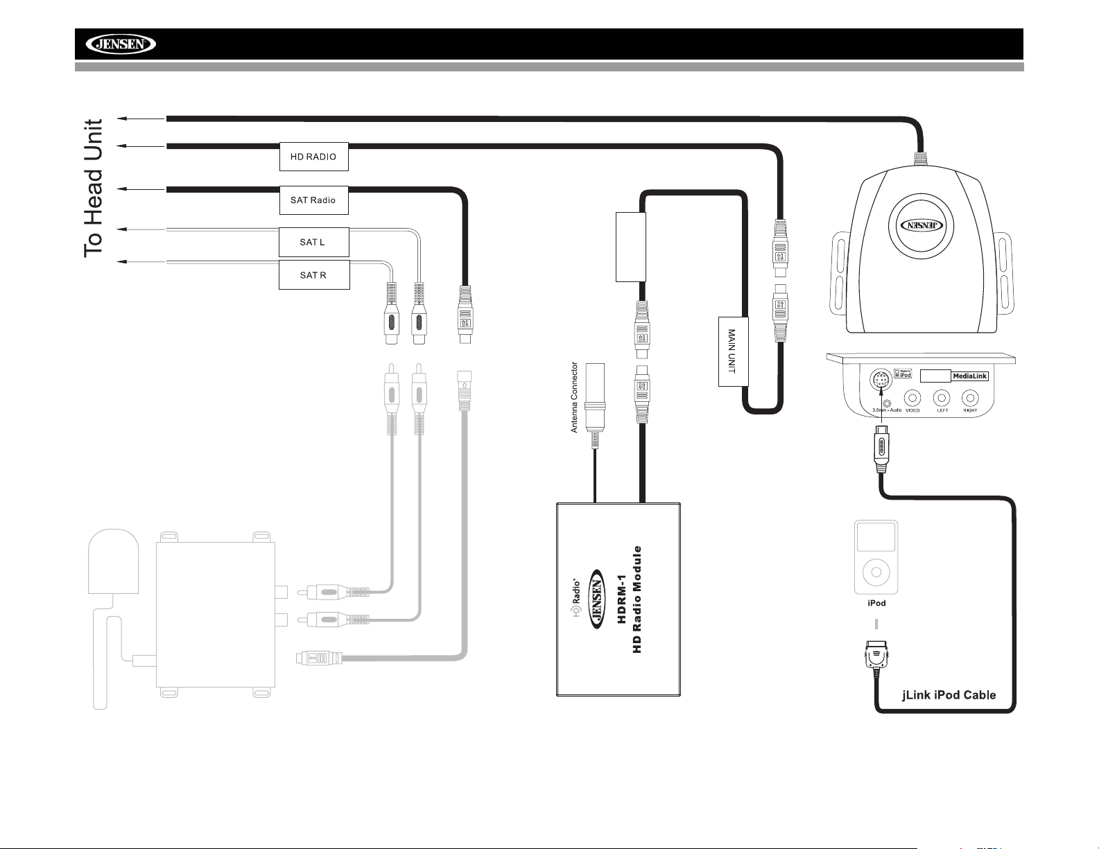
MODULE CONNECTIONS
Compatible SAT Tuners:
1. XMD1000 (requires XMC or
XMDJEN100 Cable Kit)
2. CNP2000UC
HD RADIO
MODULE
VM9022HDN
Requires Gen 5.5 or
*
earlier photo or video
iPod. iPhone, iPod
Touch, iPod Classic
and iPod Nano with
video will only play
music files.
*
4
Page 9
VM9022HDN
INSTALLATION
ISO DIN Installation
This unit is designed to fit into a 2.0 DIN dashboard opening,
found in many imported cars. The unit has threaded holes in
the chassis side panels which may be used with the original
factory mounting brackets of some Toyota, Nissan,
Mitsubishi, Isuzu, Hyundai and Honda vehicles to mount the
radio to the dashboard. Please consult with your local car
stereo specialty shop for assistance on this type of
installation.
1. Remove the existing factory radio from the dashboard or
center console mounting. Save all hardware and brackets as they will be used to mount the new radio.
2. Remove the factory mounting brackets and hardware
from the existing radio and attach them to the new radio.
ISO INSTALLATION
CAUTION: For proper operation of the CD player, the
chassis must be mounted within 30° of horizontal. Make
sure the unit is mounted within this limitation.
NOTE: It is the end-users responsibility to install and
operate this unit in a manner in accordance with local,
state and federal laws. The PARKING BRAKE wire MUST
BE CONNECTED as directed in the manual.
CAUTION: Do not block the cooling fan exit. If blocked,
the unit may overheat and become damaged.
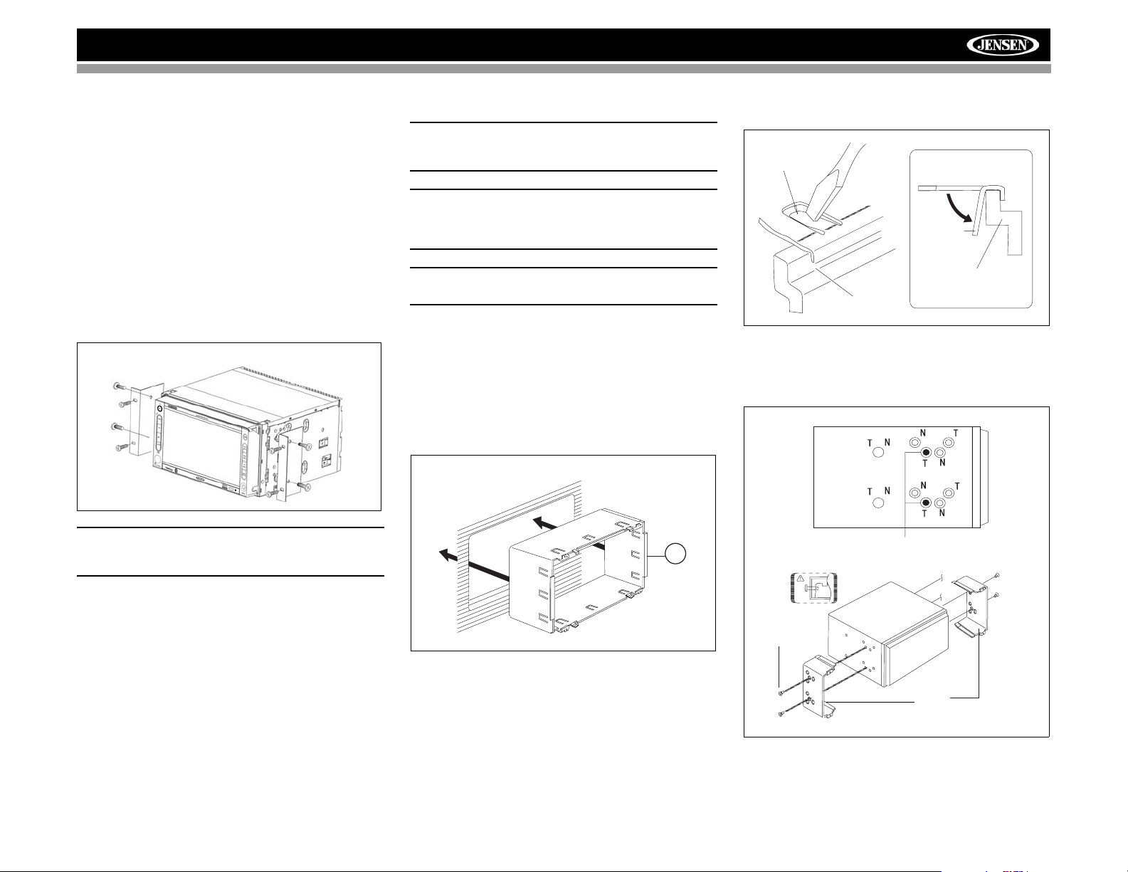
Installation Using Half-Sleeve
1. Press the metal levers on both sides to remove the halfsleeve from the radio.
2. Install the half-sleeve.
a. Install adapter if necessary (optional).
b. Install half-sleeve into adapter or dashboard (use only
the supplied screws). Do not force the sleeve into the
opening or cause it to bend or bow.
TAB
TAB
DASHBOARD
DASHBOARD
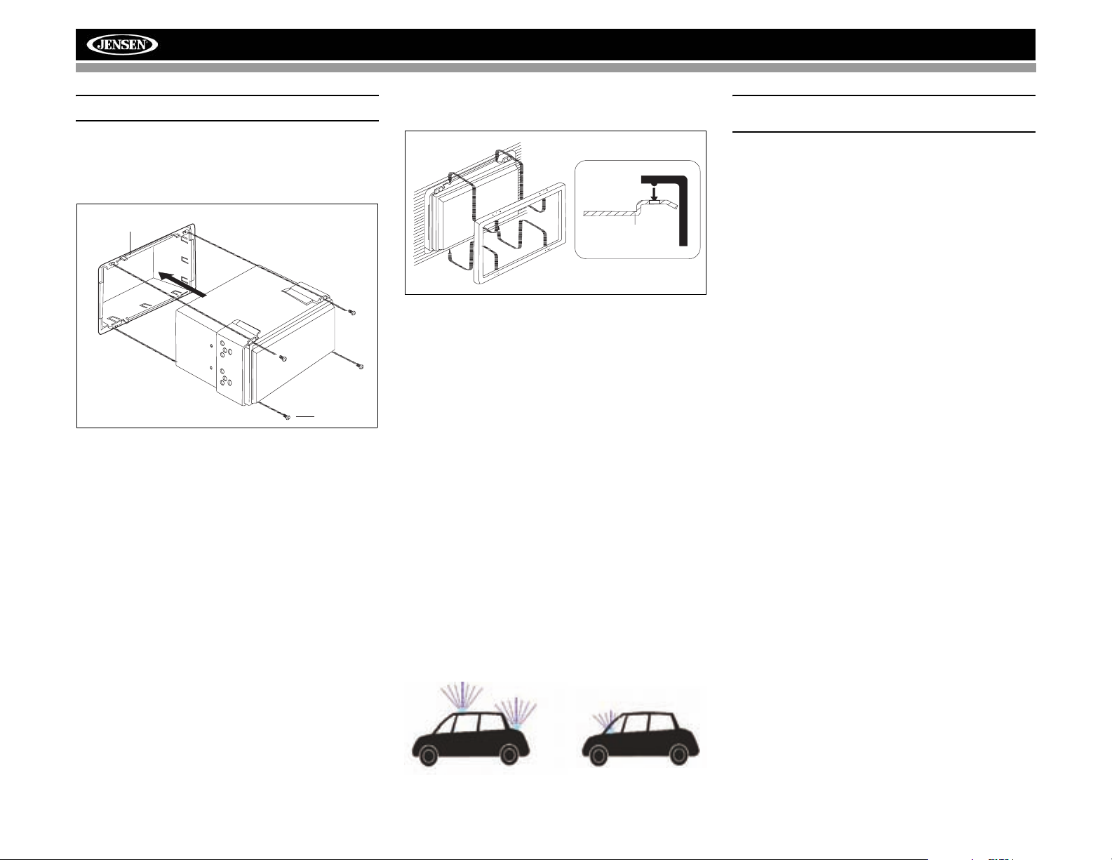
3. Use the M5 x 6 screws (provided) to install the mounting
brackets to each side of the radio using the holes
indicated below.
CAUTION: Do not exceed M5 X 6MM screw size. Longer
screws may touch and damage components inside the
chassis.
3. Place the radio in front of the dashboard opening so the
wiring can be brought through the mounting sleeve.
Follow the wiring diagram carefully and make certain all
connections are secure and insulated with wire nuts or
electrical tape. After completing the wiring connections,
plug the ISO connectors into the mating sockets on the
rear of the chassis. Turn the unit on to confirm operation
(vehicle ignition switch must be “on”). If the unit does not
operate, re-check all wiring until the problem is
corrected.
4. Mount the new radio assembly to the dashboard or
center console using the reverse procedure in step 1.
INSTALL HALF SLEEVE
2b
c. Locate the series of bend-tabs along the top, bottom
and sides of the mounting sleeve. With the sleeve fully
inserted into the dashboard opening, bend as many of
the tabs outward as necessary so that the sleeve is
firmly secured to the dashboard.
5
Install Bracket Here
Non-Designated
Screw Prohibited
M5X6
SCREW
BRACKET
4. Place the radio in front of the dashboard opening so the
wiring can be brought through the mounting sleeve.
Page 10
VM9022HDN
CAUTION! Be careful not to damage the car wiring.
5. Complete wiring as illustrated in the wiring diagram on
page 3. Once the wiring is complete, reconnect the
battery negative terminal. If there is no ACC available,
connect the ACC lead to the power supply with a switch.
MOUNTING SLEEVE
M3x4
SCREW
After completing the wiring connections, turn the unit on to
confirm operation (ignition switch must be on). If unit does not
operate, recheck all wiring until problem is corrected. Once
proper operation is achieved, turn off the ignition switch and
proceed with final mounting of the chassis.
1. Connect wiring adapter to existing wiring harness.
2. Connect antenna lead.
3. Carefully slide the radio into the half-sleeve, making
sure it is right-side-up, until it is fully seated and the
spring clips lock it into place.
Using the Cosmetic Trim Ring
Two cosmetic trim rings are packaged with the VM9022HDN
for installation flexibility. The VM9022HDN will fit into most
import dashes with little or no modification to the dashboard
or cavity. Some US domestic vehicle dashes will accept a
Double-DIN chassis, but there is usually a small gap between
the radio and dash piece after installation is complete. In this
case, use the appropriate trim ring to conceal any gaps that
may be present.
The 4 tabs on the trim ring will snap into four holes on top and
bottom of the mounting sleeve.
TRIM RING
OPTIONAL
MOUNTING
TRIM RING
SLEEVE
Installing the MediaLink External AV
Connector
The MediaLink allows you to connect a variety of external
devices, including a VCR, DVD player, portable MP3 player,
etc., to your VM9022HDN without removing the radio.
To install the MediaLink, connect it to the AUX-IN cables on
the back of the VM9022HDN (see the Wiring Diagram on
page 3), and then install the MediaLink in a location
convenient for plugging in auxiliary devices.
Installing the Navigation Antenna
The VM9022HDN utilizes an external GPS antenna that must
be installed before accessing navigation features.
Since the navigation module uses GPS technology for
navigation, proper antenna placement is crucial for optimal
performance of the GPS receiver. When using GPS
antennas, the antenna plane should be parallel to the
geographic horizon. There should be nothing between the
antenna and the sky to ensure a direct line-of-sight between
the antenna and available satellites.
The preferred antenna location is on the top of the car on the
roof or trunk area. When placed on the dashboard,
performance may be reduced due to obstruction caused by
the window or roof.
NOTE: Do not cut the GPS antenna cable to shorten or
lengthen it.
Replacing the Fuse
When replacing the fuse, use a new 20A replacement fuse.
Using a fuse with an improper rating could damage the unit
and cause a fire.
6
Page 11
VM9022HDN
RADIO
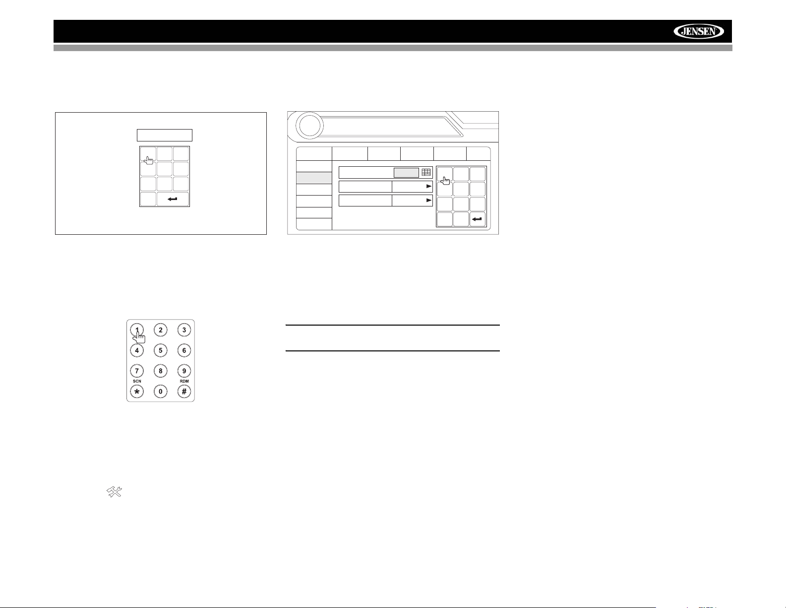
ANTI-THEFT FEATURE
The VM9022HDN is equipped with an anti-theft feature
requiring the user to enter a password upon initial power on.
Enter Password:
1
2
3
6
5
4
9
8
7
0
3. Touch the keypad icon next to the blue box in the
“Password” field to open the on-screen keypad.
02:40
SETUP
General
RDS
Rating
Demo
Hardware
P.VOL
TS Cal
Language
Password
Rating 8. Adult
Load Factory Reset
Audio
Speaker
Bluetooth
1
4
7
Clear
0
2
5
8
AM
Back
3
6
9
Entering the Default Password
The default user password is 012345 (6 digits). Enter the
password using the on-screen keypad and then press the
Enter (arrow) button. You can also use the remote control
keypad to enter the password.
Press the joystick Enter button (18) on the remote control to
confirm.
Changing the Password
To change the anti-theft and RATINGS protection password,
perform the following steps:
1. Press the SETUP button (31) on the remote control or
touch the button on the screen to enter the
“SETUP” menu.
2. Touch RATING to view the “RATING” sub-menu. An
open lock icon to the right of the “Password” field
indicates that a user password had not yet been
entered.
4. Enter a new 6-digit password and press the Enter
(arrow) button.
The "lock" icon will now appear closed and the new antitheft password will be set, as well as the password for
RATING protection (see “Rating Sub-menu Features”
on page 18).
NOTE: If you forget your password, contact Customer
Service at 1-800-323-4815 for assistance.
7
Page 12
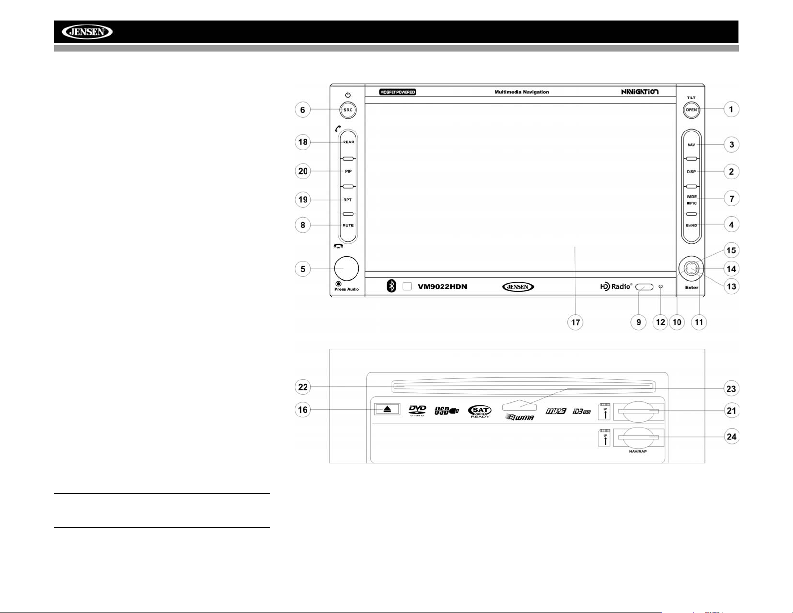
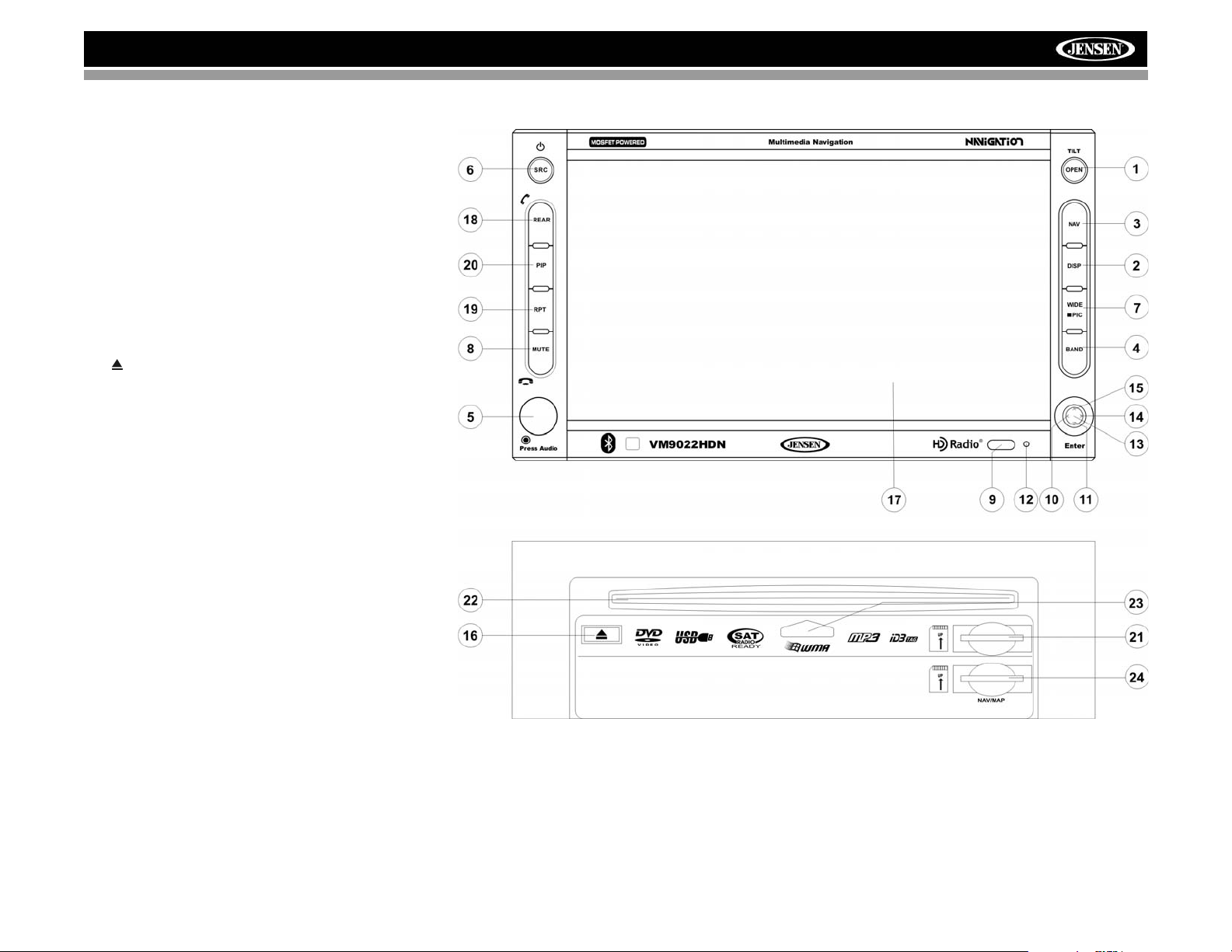
CONTROLS AND INDICATORS
Button Operation
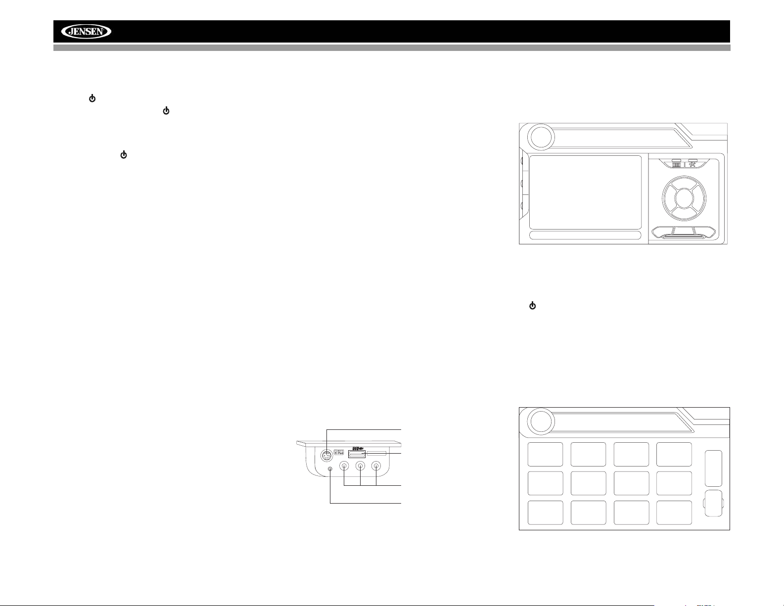
1. OPEN/TILT
Press to activate the automatic mechanical system and move
the TFT monitor into viewing position. Press again to close
the TFT.
Press and hold to activate the screen tilt function (use the
joystick to adjust the angle).
2. DISP
Press to cycle through information available on the TFT
screen.
In DVD Mode, press to view the top and bottom information
bars. Press again to turn “Display Off”.
3. NAV
Press to access Navigation Mode.
4. BAND
Press the BAND button to change the AM, FM or SAT band.
5. AUDIO
Rotate to adjust the volume. Press to enter and/or confirm
audio settings.
6. SRC
Press to select playing mode.
When you change the source during navigation, the voice
prompts will still be heard, although the navigation map
cannot be seen. (The selected source audio will be muted
until the navigation voice prompt command is completed,
after which the source audio will resume.)
7. WIDE/PIC
Press to adjust the display aspect of the picture to one of
three settings: CINEMA, NORMAL or Standby (screen off).
Touch the screen to turn Standy mode off. NOTE: Only
CINEMA and Standby are available for non-video sources.
Press and hold to adjust Brightness and Contrast.
8. MUTE
Press to silence the receiver. Press again to resume the
previous volume level.
BT Mode: Answer/dial Bluetooth call.
NOTE: The VM9022HDN features Softmute, which will
allow the volume to increase or decrease gradually when
the MUTE function is activated or deactivated.
9. IR Remote Control Receiver
10. (left joystick)
DVD/Disc Mode: Press once to play back the previous
chapter/track.
TUNER Mode: Press once to auto-search for the previous
available radio station.
MENU Mode: Press once to move the cursor to the left.
VM9022HDN
11. (down joystick)
DVD/Disc Mode: Press once for slow forward/slow reverse.
TUNER Mode: Press to go down one frequency step.
MENU Mode: Press once to move the cursor down.
12. Reset
Press to reset system settings to factory default (except the
password and parental lock setting).
8
Page 13
VM9022HDN
CONTROLS AND INDICATORS
13.Pause/Play/Enter
Press to pause or resume playback or to confirm current
selection.
14. (right joystick)
DVD/Disc Mode: Press once to enter the next chapter or
track.
TUNER Mode: Press once to auto-search the next available
radio station.
MENU Mode: Press once to move the cursor to the right.
15. (up joystick)
DVD/Disc Mode: Press once for fast forward/fast reverse.
TUNER Mode: Press to go up one frequency step.
MENU Mode: Press once to move the cursor up.
16. ( )
Press once for disc insertion/ejection.
Press and hold to reset core mechanism position.
17. TFT Display
18. REAR
Select rear zone source. Allows front passengers to listen to
the radio while rear passengers listen to a CD, MP3, WMA or
watch DVDs.
BT Mode: Disconnect Bluetooth call.
19. RPT
Press to control repeat playback function.
20. PIP
Press to activate the Picture In Picture function.
21. SD Card Slot
Insert SD card for playback of audio files.
22. Disc Slot
23. Disc Loaded Indicator
24. NAV/MAP SD Card Slot
Insert Jensen Navigation Map Data 2GB SD card (included).
9
Page 14
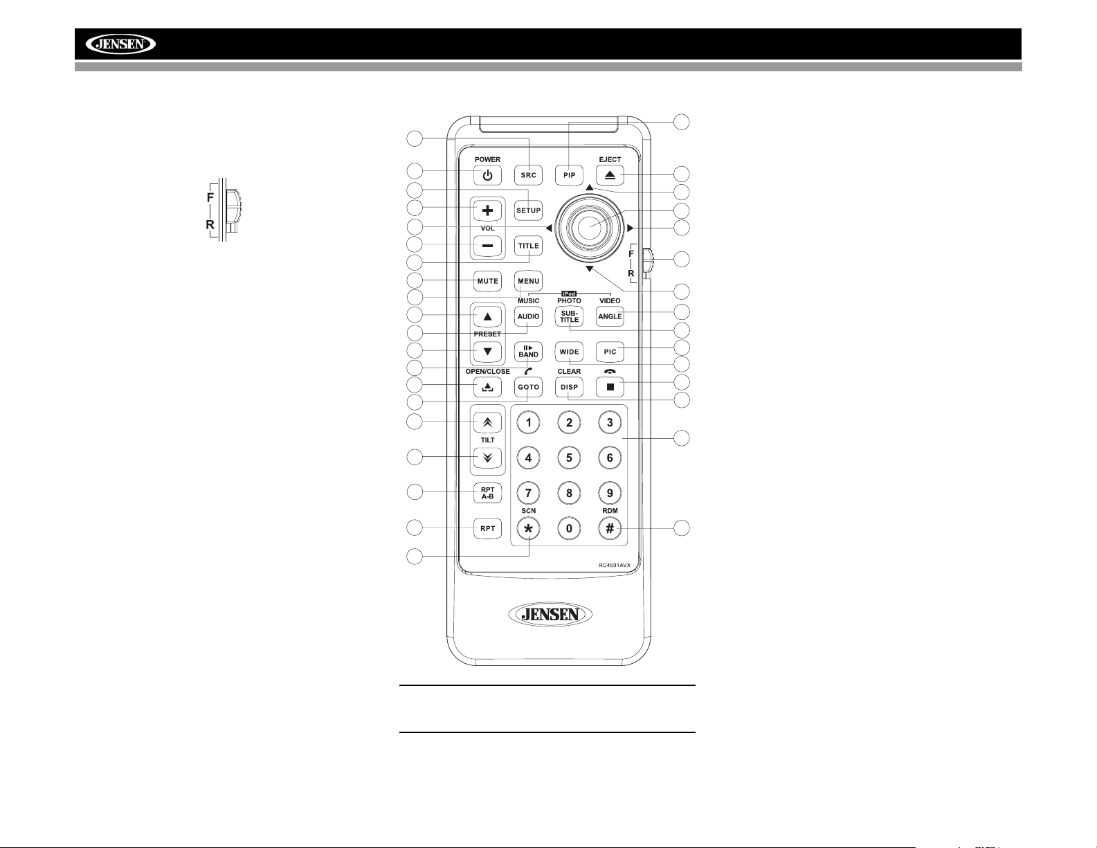
REMOTE CONTROL
The VM9022HDN Remote controls both the front and rear
zones. To switch from front to rear zone, move the F/R switch
(32) located on the right side of the controller.
VM9022HDN
30
8
4
31
16
17
15
2
3
1
11
5
12
23
25
21
27
26
6
7
34
35
14
18
19
32
22
13
9
24
28
20
10
29
33
NOTE: Your remote control may differ slightly from the
one pictured here. The above diagram is for illustrative
purposes only.
10
Page 15
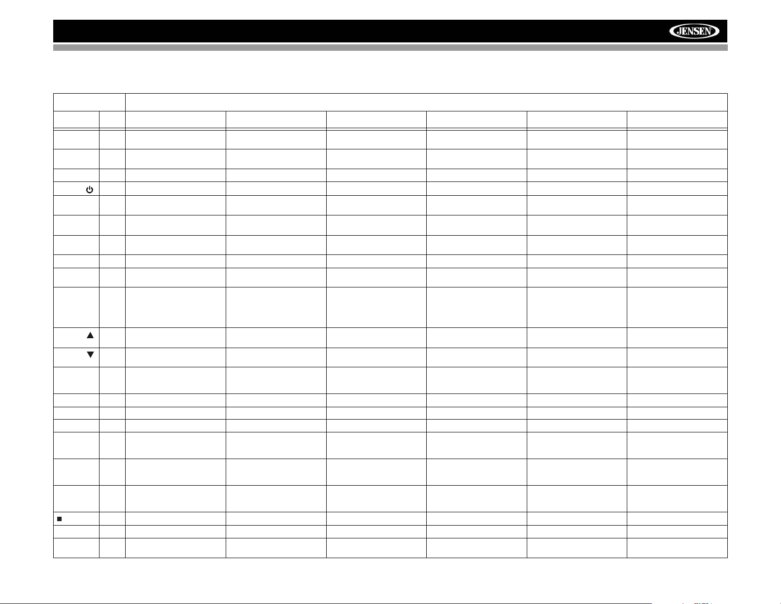
VM9022HDN
Table 1: Remote Control Functions
Button Function
Name Ref# DVD VCD TUNER CD/MP3 SATELLITE iPod
MENU 1 Enters the main menu of the
TITLE 2 Enters the title menu of the
MUTE 3 Toggles on/off audio output Toggles on/off audio output Toggles on/off audio output Toggles on/off audio output Toggles on/off audio output Toggles on/off audio output
POWER/
AUDIO 5 Changes the audio language
RPT A-B 6 Setup to repeat playback from
RPT 7 Repeats chapter/title Repeats track/disc Repeats track/folder/disc Repeats playback of current
SRC 8 Selects playing source Selects playing source Selects playing source Selects playing source Selects playing source Selects playing source
SUBTITLE 9 Language selection for subti-
DISP/
CLEAR
PRESET
PRESET
ANGLE 13 Plays back disc in different
Joystick /\ 14 Fast forwards the disc content Fast forwards the disc content Fast forwards the disc content Accesses iPod Menu
VOL - 15 Decreases volume Decreases volume Decreases volume Decreases volume Decreases volume Decreases volume
VOL + 16 Increases volume Increases volume Increases volume Increases volume Increases volume Increases volume
Joystick < 17 Selects the previous chapter
Joystick
(press)
Joystick > 19 Selects the next chapter for
GOTO 21 Enters Direct Access mode Enters Direct Access mode Enters Direct Access mode Enters Direct Access mode Enters Direct Access mode Enters Direct Access mode
Joystick \/ 22 Fast reverses the disc content Fast reverses the disc content Fast reverses the disc content Pauses playback/starts play-
disc
disc
4 Turns the power on/off Turns the power on/off Turns the power on/off Turns the power on/off Turns the power on/off Turns the power on/off
for disc playback
time frame A to time frame B
tle
10 Displays playing information/
Delete entry or move backwards to correct error in Direct
Access mode
11 Zooms in when playing DVD
or Photo
12 Zooms out when playing DVD
or Photo
angle (if available) for a scene
for playback
18 ENTER, Pauses playback/
starts playback
playback
20 Stops playback Stops playback Stops playback
Turns on/off PBC when playing VCD
Plays first ten seconds of each
chapter/title
Setup to repeat playback from
time frame A to time frame B
Displays playing information/
Delete entry or move backwards to correct error in Direct
Access mode
Zooms in Navigates the preset station
Zooms out Navigates the preset station
Plays back Picture CD with
different angle (if available) of
picture displayed
Selects the previous chapter
for playback
ENTER, Pauses playback/
starts playback
Selects the next chapter for
playback
Displays audio mode
Delete entry or move backwards to correct error in Direct
Access mode
list
list
Switches MEM keypad off Selects Video mode Switches MEM keypad off Selects iPod Video mode
Searches an available radio
station by decreasing tuning
frequency
Auto memory scan ENTER, Pauses playback/
Searches an available radio
station by increasing tuning
frequency
Displays diagnostics screen Displays iPod menu
Category list in CG mode
Selects Music mode Selects iPod Music mode
track
Selects Photo mode Selects iPod Photo mode
Displays audio mode
Delete entry or move backwards to correct error in Direct
Access mode
Navigates list window Navigates the preset station
Navigates list window Navigates the preset station
Selects the previous track for
playback
starts playback
Selects the next track for playback
Displays audio mode
Delete entry or move backwards to correct error in Direct
Access mode
list
list
Searches an available radio
station by decreasing tuning
frequency
ENTER, Toggles the onscreen menu between CAT/
CH mode
Searches an available radio
station by increasing tuning
frequency
Displays audio mode
Delete entry or move backwards to correct error in Direct
Access mode
Navigates list window
Navigates list window
Selects prior track
ENTER
Selects the next track for playback
back
11
Page 16
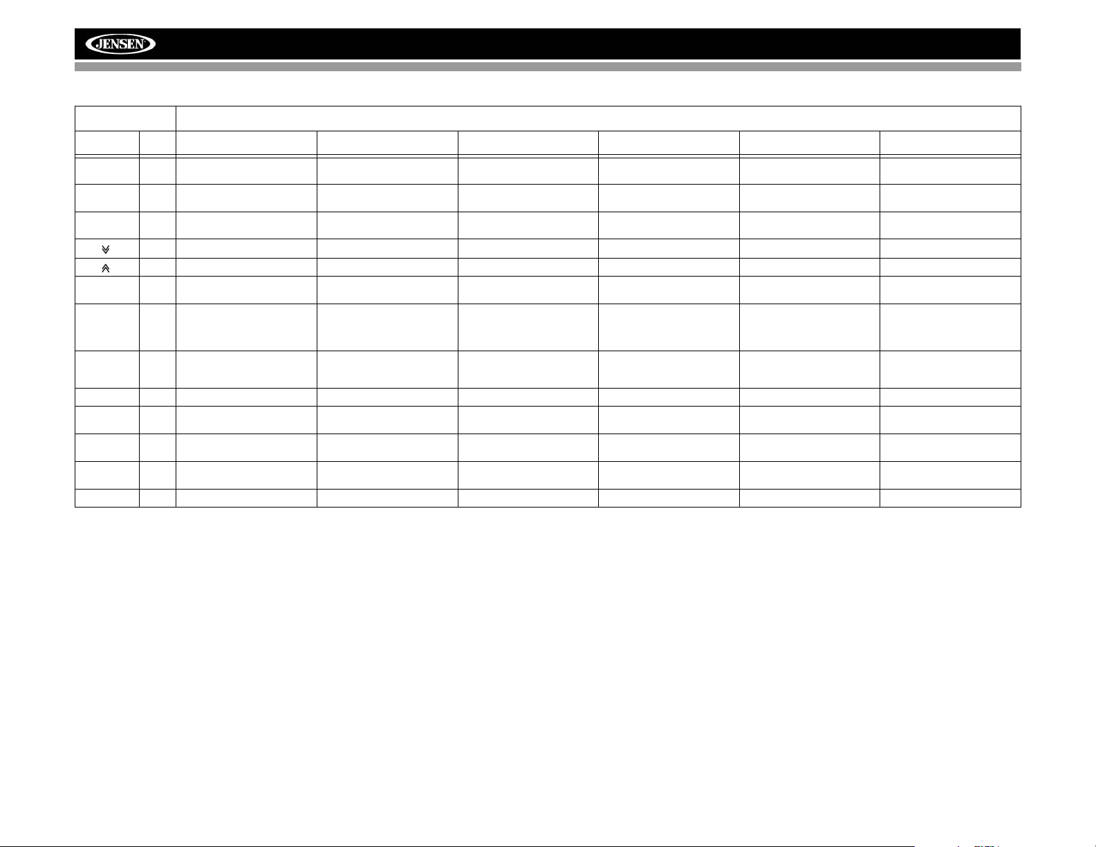
VM9022HDN
Table 1: Remote Control Functions
Button Function
Name Ref# DVD VCD TUNER CD/MP3 SATELLITE iPod
||>/BAND 23 Slow Forward/Slow Reverse
PIC 24 Displays Brightness/Contrast
OPEN/
CLOSE
TILT
TILT
WIDE 28 Selects display mode: CIN-
1, 2, 3, 4, 5,
6, 7, 8, 9, 0
(Numeric
Keypad)
PIP 30 Picture In Picture view of
SETUP 31 Displays Setup menu Displays Setup menu Displays Setup menu Displays Setup menu Displays Setup menu Displays Setup menu
F/R 32 F controls front zone
RDM 33 Plays all chapters in random
SCN 34 Preview scan Plays the first ten seconds of
EJECT 35 Ejects disc Ejects disc Ejects disc Ejects disc Ejects disc Ejects disc
X2, X4, X8
Controls
25 Opens/closes the TFT monitor Opens/closes the TFT monitor Opens/closes the TFT monitor Opens/closes the TFT monitor Opens/closes the TFT monitor Opens/Closes the TFT moni-
26 Decreases monitor tilt angle Decreases monitor tilt angle Decreases monitor tilt angle Decreases monitor tilt angle Decreases monitor tilt angle Decreases monitor tilt angle
27 Increases monitor tilt angle Increases monitor tilt angle Increases monitor tilt angle Increases monitor tilt angle Increases monitor tilt angle Increases monitor tilt angle
EMA, NORMAL or Standby
29 Directly accesses chapter 1-18 selects preset for current
Front source, Rear Zone or
NAV
R controls rear zone
order
Slow forward X2, X4, X8 Selects AM/FM Band. Selects SAT1, SAT2 or SAT3
Displays Brightness/Contrast
Controls
Selects display mode: CINEMA, NORMAL or Standby
Picture In Picture view of
Front source, Rear Zone or
NAV
F controls front zone
R controls rear zone
Displays Brightness/Contrast
Controls
Selects display mode: CINEMA or Standby
band
Picture In Picture view of
Front source, Rear Zone or
NAV
F controls front zone
R controls rear zone
Displays Brightness/Contrast
Controls
Selects display mode: CINEMA or Standby
Directly accesses track 1-6 selects preset for current
Picture In Picture view of
Front source, Rear Zone or
NAV
F controls front zone
R controls rear zone
Plays all tracks in random
order
each track
band.
Displays Brightness/Contrast
Controls
Selects display mode: CINEMA or Standby
band
Picture In Picture view of
Front source, Rear Zone or
NAV
F controls front zone
R controls rear zone
Preview scan
Displays Brightness/Contrast
Controls
tor
Selects display mode: CINEMA or Standby
Picture In Picture view of
Front source, Rear Zone or
NAV
F controls front zone
R controls rear zone
Plays all tracks in random
order
12
Page 17
VM9022HDN
USING THE TFT MONITOR
Open/Close TFT Monitor
Open TFT Monitor
Press the OPEN button (1) on the front panel or press the
( ) button (25) on the remote control to slide the monitor
panel down to reveal the disc and SD card slots.
Close TFT Monitor
Press the OPEN button (1) on the front panel or press the
( ) button (25) on the remote control close the monitor
panel.
Monitor Tilt Angle Adjustment
A known characteristic of LCD panels is the quality of the
display in relationship to the viewing angle. The monitor
angle can be adjusted for optimum viewing using one of the
following methods.
Step by Step Angle Adjustment
Press the ( ) or ( ) button on the remote control (26, 27)
to adjust the tilt angle of the screen one step at a time.
Continuous Angle Adjustment
Press and hold the ( ) or ( ) button on the control panel
or remote control to adjust the tilt angle in a continuous
motion.
Reverse Driving Use
If the rear-view video camera is connected, the unit is on, and
the monitor is stationed inside the main compartment of the
unit, the monitor automatically moves into the viewing
position and switches to CAMERA mode upon reverse
driving. When the reverse driving stops, the monitor returns
to the main storage compartment.
If the monitor is in display mode, the monitor automatically
switches to CAMERA mode upon reverse driving. When the
reverse driving stops, the monitor returns to its original input
mode.
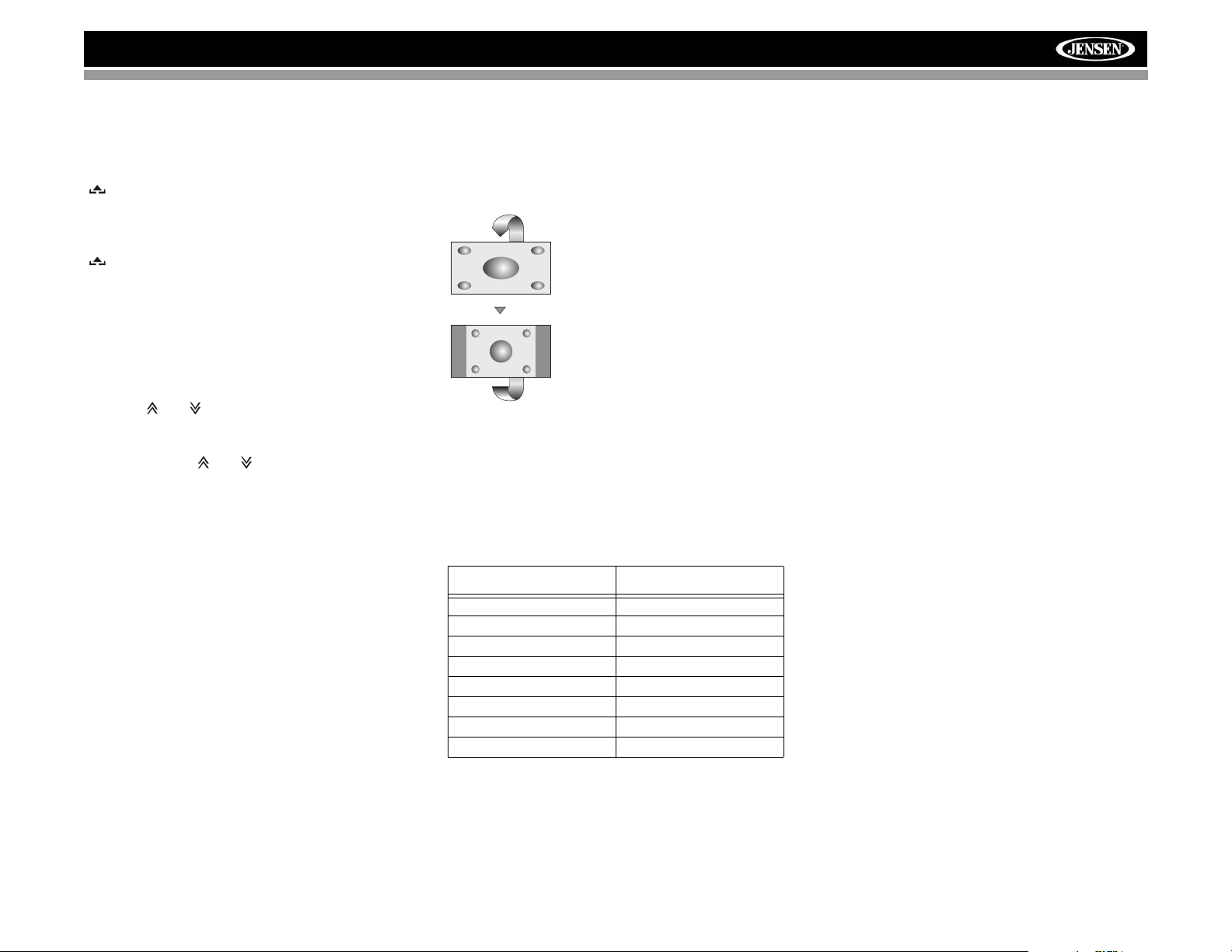
Aspect Ratio
Press the WIDE button (28) on the remote control or WIDE/
PIC button (7) on the monitor to adjust the aspect ratio as
follows (only active with video source):
CINEMA
The entire screen is extended
horizontally to the aspect ratio of 16 to
9. The extension ratio is the same at
any point.
NORMAL
The conventional display image has a
4 to 3 ratio of horizontal to vertical,
leaving a blank area on the right and
left sides of the display.
STANDBY
Screen becomes black. Touch screen
to resume.
Image Setting
Table 2 shows the video output mode for each playing
source.
Table 2: Video Output Modes
Playing Source Video Output Modes
RADIO RGB Mode
SAT RGB Mode
DISC RGB Mode
BT RGB Mode
AUX 1 CVBS Mode
AUX 2 CVBS Mode
NAV RGB Mode
CAMERA CVBS Mode
*CVBS – Composite Video Baseband Signal
Parameter Adjustment Procedure
1. Enter Picture Quality Setting Mode:
Press the PIC button (24) on the remote control or press
and hold the WIDE/PIC button (7) on the monitor.
2. Select Item to Set:
Use the up/down joystick buttons to select “BRIGHT” or
“CONTRAST”.
3. Set Parameters:
Use the left/right joystick buttons to modify the settings.
4. Exit Picture Quality Setting Mode:
Press the PIC button on the remote control or the WIDE/
PIC button on the monitor
Parking Brake Inhibit
When the pink "Parking" wire is connected to the vehicle
Parking Brake circuit, the front TFT monitor will display video
when the Parking Brake is engaged. (When the pink wire is
grounded via the Parking Brake circuit, video will be
displayed.)
13
Page 18
AUX1
DISC
OPERATING INSTRUCTIONS
Power On / Off
Press the /SRC button (6) (or any other button on the front
of the unit except reset), or the /POWER button (4) on the
remote control, to turn the unit on. The buttons on the front of
the unit light up and the current mode status appears on the
TFT screen (17).
Press and hold the button to power off the unit.The monitor
is drawn back into the main compartment.
Audible Beep Confirmation
An audible beep tone confirms each function selection. The
Beep tone can be disabled through the Setup menu.
Volume Adjustment
To increase or decrease the volume level, turn the rotary
encoder (5) on the front panel or press the VOL+/ VOL-
buttons (15, 16) on the remote control. When the volume
level reaches “0” or “40”, a beep sounds, indicating that the
adjustment limit has been reached. The volume ranges from
“0” to “40”. The TFT screen displays the volume level for 3
seconds.
Programmable Turn-On Volume
This feature allows the user to select a turn-on volume setting
regardless of the volume setting prior to turning the unit off.
To program a specific turn-on volume level, turn the AUDIO
control (2) to adjust the volume to the desired turn-on volume.
Push and hold the AUDIO button while the yellow speaker
icon and level indication is displayed on the screen. The unit
will beep two times to confirm your turn-on volume setting.
Mute
Press the MUTE button on the front panel (8) or remote
control (3) to mute the volume from the unit. Press the MUTE
button again to restore the volume. “MUTE” is displayed on
the screen. Adjusting the volume or using any of the audio
setup features cancels the mute function.
Line Mute
If the “MUTE” wire is connected, audio output mutes when a
telephone call is received by a cell phone.
Steering Wheel Control (SWC)
The VM9022HDN is compatible with the PAC (Pacific
Accessory Corporation) steering wheel control adapter SWIPS. A 3.5mm female connector (labeled “SWC Interface”) on
the back of the head unit allows connectivity to the PAC
adapter. Please refer to the instructions included with the
PAC adapter for detailed installation information.
SWC Functions
The following controls are available for most vehicles:
1. Vol Up
2. Vol Down
3. Mute
4. Seek Up / Next Track / ** Preset Up
5. Seek Down / Previous Track / ** Preset Down
6. SRC (Source)
7. ** Select
8. ** Select
9. Band
** If additional steering wheel control buttons are available on
the vehicle, function 7 / 8 may be assigned the "Select"
feature. This feature / function may not be available on some
vehicles.
Select Operation
If "Select" (function 7 or 8) is held down and function 4 is
pressed momentarily, Preset Up will be selected. If "Select"
(function 7 or 8) is held down and function 5 is pressed
momentarily, Preset Down will be selected.
Playing Source Selection
Press the SRC button on the front panel (6) or remote control
(8) to change between available playing sources in the
following order: RADIO, SAT, DISC, NAV, BT, iPod, SD, USB,
AUX1, AUX2 and CAMERA. The playing mode is displayed
on the TFT screen.
Auxiliary Devices
External peripheral devices can be connected to this unit via
RCA output (AUX IN 2) or the MediaLink
MediaLink
3.5mm -Audio
VIDEO LEFT RIGHT
Select “AUX1” to play an auxiliary device connected via the
MediaLink RCA or 3.5mm inputs. For example, you can play
4
.
iPod Connector
(GEN 5 Recommended)
USB Connector (Type A)
RCA Inputs (AUX 1)
3.5mm Left & Right
Stereo Inputs (AUX 1)
VM9022HDN
music files from a portable music player, video from a video
camera and even view photos stored on a digital camera.
Select “AUX2” mode to access and control auxiliary devices
No Video Signal
E
Q
R
E
A
R
P
I
P
Stereo PLII Music
01:53 PM
connected to the “AUX IN 2” inputs on the back of the radio.
Selecting a Source while Navigating
While navigating, other sources may be selected and listened
to such as AM-FM Tuner, CD, etc. To select a source, press
the /SRC button (6) and then select a source from the Front
Source Menu. Navigation voice prompts will be heard
automatically, although the navigation map cannot be seen.
(The selected source audio will be muted until the navigation
voice prompt command is completed, after which the source
audio will resume.)
Source Menu
To access the SOURCE MENU, touch the TFT screen in the
top left corner of the screen.
SOURCE MENU
DISC
RADIO
AUX 1
SAT
AUX 2
SD
USB
iPod
CAMERA
NAV
OFF
F
R
O
N
T
BT
R
E
A
R
14
Page 19
VM9022HDN
DISC
n
This menu allows you to select a source for the front or rear
zone. Touch FRONT or REAR to choose the zone for which
you would like to specify the source. (See “Multi-ZONE
Operation” on page 16.)
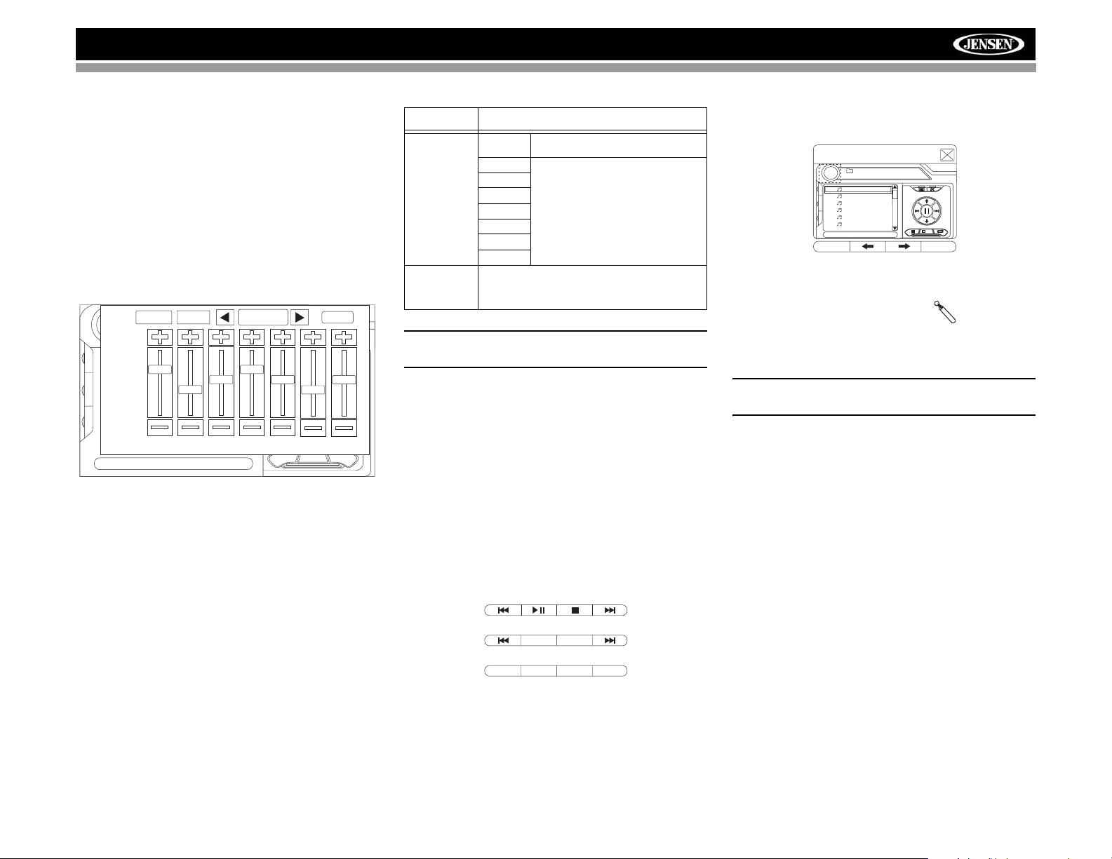
Audio Control Menu
The Audio Control menu features a 7-band graphic equalizer,
which allows you to easily adjust your audio system to meet
the acoustical characteristics of your vehicle, which vary
depending on the type of vehicle and its measurements.
Proper setting of the Fader and Balance boosts the effects of
the cabin equalizer.
Press the AUDIO button (5) on the front panel to display the
audio menu.
E
Q
R
E
A
R
P
I
P
FAD-BAL EQ
+12 —
0—
–12 —
80 250 600 1k 4k 10k 16k
EQ: User
USER
To adjust an audio feature:
1. Use the left/right joystick buttons to highlight the audio
feature to be adjusted.
2. Press the joystick Enter button on the control panel (13)
or remote control (18) to select the highlighted option.
3. Use the joystick to adjust the selected feature to the
desired setting.
BACK
Table 3: Audio Adjustments
Function Adjustment Options
EQ User In user mode, you can manually adjust
Acoustic Use the on-screen arrows to select a
Urban
Rave
Latin
Dance
Hip Hop
Rock
FAD-BAL Use this screen to adjust the output level for each
NOTE: The EQ mode will automatically change to
“USER” when individual EQ bands are adjusted.
speaker in your surround system from 0 to -24dB.
You can also adjust the master volume from this
screen.
Proper setting of the Fader and Balance complement the
effects of the cabin equalizer.
The Audio menu will automatically exit after a few seconds of
inactivity. To exit quickly, touch the top left corner of the
screen or press and hold the AUDIO button (5).
each of the seven frequency bands.
predefined equalization curve.
Alternate Display Options
A menu located on the left side of the screen provides
immediate access to the Equalizer, Rear Zone screen view
and PIP (Picture in Picture) features.
• EQ: Touch to view Spectrum Analyzer > Equalizer.
• REAR: Touch to view the Rear Zone screen. Control
options appear below the PIP image, depending on the
source.
DISC
• PIP: Touch to view the Rear Zone, current Front Zone,
or NAV screen. Use the left/right arrows below the PIP
image to change the PIP source.
PIP: DISC
(Root)
MP3 4/84 00:00:23
E
1 Cherry Poppin Da
Q
2 Chris Isaak - Baby
R
E
3 Crazy Town - Butt
A
R
4 Phish - Birds Of A
P
I
5 Phish - Bouncin' R
P
6 Phish - Freebird (L
01:02 AM
1/2
System Reset
To correct a system halt or other
illegal operation, use the tip of a pen
to press the reset button (12) located
on the front bottom-right corner of the unit. After a system
reset, the unit restores all factory default settings.
NOTE: If the unit is reset while a DVD is playing, the DVD
resumes play once the reset is complete.
[RESET] Butto
AM/FM RADIO
BAND AS
CAT– CH– CH+ CAT+
SATELLITE
15
Page 20
MULTI-ZONE OPERATION
DISC
Independent sources can be played simultaneously on the
VM9022HDN. For example, a video game console can be
seen on the front screen while DVD video is available to rear
passengers.
DVD and SD Card sources cannot be selected
for simultaneous Front / Rear operation. For
example, if DVD is selected as the Rear Zone
source, then SD Card cannot be selected as a
Front Zone source. In addition, HD Radio and
SAT cannot be selected for simultaneous
Front / Rear operation.
Table 4: Multi-Zone Source Options
FRONT
ZONE
HD
Disc SD USB NAV SAT iPod BT Aux 1 Aux 2 Cam
Radio
HD
OOOOOXOXOOO
Radio
DiscOOXOOOOXOOO
SDOXOOOOOXOOO
USBOOOOOOOXOOO
NAVOOOOOOOXOOO
SATXOOOOOOXOOO
iPodOOOOOOOXOOO
BTOOOOOOOOOOO
Aux 1OOOOOOOXOOO
Aux 2OOOOOOOXOOO
CamOOOOOOOOOOO
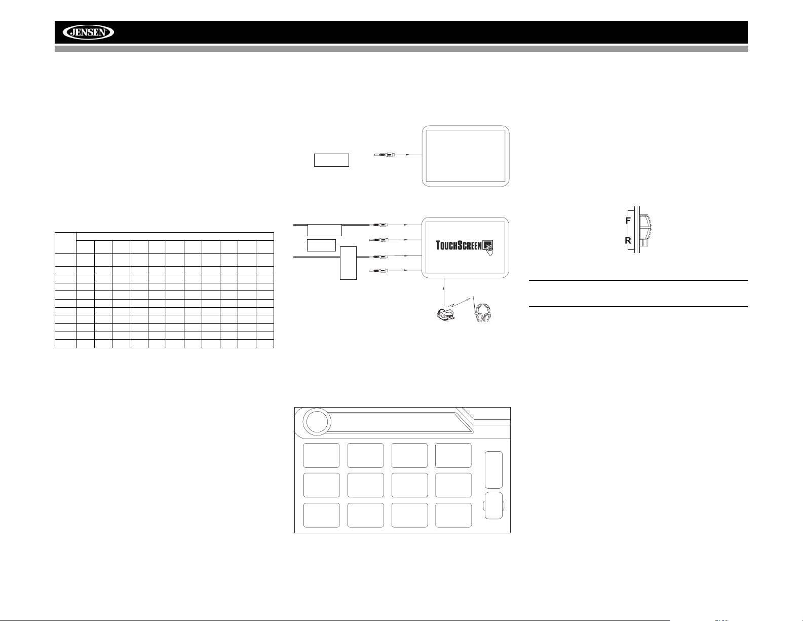
Connecting the Rear Zone Touch
Screen
You can connect up to two additional monitors (sold
separately) for rear passengers, one of which can be a Touch
Screen.
REAR ZONE
Y ou can also connect a wireless headphone system to one of
your rear monitors, as illustrated below.
Rear Video Screen
(Sold Separately)
YELLOW
VIDEO OUT 1
MZ7-TFTTouchScreen
(Sold Separately)
Wireless Headphone
(OPTIONAL)
VIDEO OUT 2
MZ7-TFT
MULTIZONE
HEADPHONE
YELLOW
BLACK
WHITE
RED
Changing the Rear Zone Source
To access the SOURCE MENU, touch the TFT screen in the
top left corner of the screen.
SOURCE MENU
VM9022HDN
This menu allows you to select a source for the front or rear
zone. Touch FRONT or REAR to choose the zone for which
you would like to specify the source.
Controlling the Rear Zone Screen(s)
If you have a rear touch screen installed, you can touch the
screen to control most rear zone functions.
You can also use the remote control. The VM9022HDN
remote controls both the front and rear zones. To switch from
front to rear zone, move the F/R switch (32) located on the
right side of the remote controller.
NOTE: You cannot change or control the front zone
source from the rear zone video screen.
Touch the REAR button on the left side of the screen to view
a “Picture in Picture” image of the rear screen.
Turning the Rear Screen Off
Touch the OFF button (on the SOURCE MENU) to suspend
operation of the rear screen. Any operation assigned
exclusively to the rear source will be suspended until
reactivated using either the front or rear zone touch screen or
the remote control.
DISC
RADIO
AUX 1
SD
SAT
AUX 2
16
USB
iPod
CAMERA
NAV
OFF
F
R
O
N
T
BT
R
E
A
R
Page 21

RADIO
VM9022HDN
SETUP MENU
To access system settings, press the SETUP button (31) on
the remote control or touch the button on the screen to
enter the “SETUP” menu. The “GENERAL” sub-menu
appears highlighted in blue.
02:40
RADIO
General
RDS
Rating
Demo
Hardware
P.VOL
TS Cal
SETUP
Language
Clock Mode 12 Hour
Clock Adjust 04 : 31 AM
Video Input AUTO
Beep On
Audio
Speaker
Bluetooth
Accessing Menu Items
Touch the sub-menu name or use the joystick to select a submenu (Language, Audio, RDS, etc.).
The features available for adjustment under the highlighted
sub-menu option will appear in the center of the screen.
Adjusting a Feature
1. Use the touchscreen or press the /\ or V buttons on the
joystick to select the feature to be adjusted.
2. Enter the option field for the feature you want to adjust
by using the touchscreen or pressing the Enter
(joystick) button. A submenu appears in a second row
with the selected option highlighted in blue.
3. Select a new value by using the touchscreen or pressing
the /\ or V buttons on the joystick.
4. Use the touchscreen or press the Enter (joystick) button
to confirm setup.
General Sub-menu Features
Setting Options Function
Clock Mode 12 Hour Clock displays 12 hour time using
24 Hour Clock displays 24 hour time up to
AM and PM.
23:59.
AM
Back
Setting Options Function
Clock Adjust (HH:MM) The clock appears in the top right
Video Input
(Input circuitry autodetects the
video signal
from the Aux
In source).
Beep On When turned on, an audible beep
NTSC The color signals are output in the
PAL The color signals are output in the
Auto The color signal output is switched
Off No beep sounds.
Language Sub-menu Features
If a DVD supports more than 1 Subtitle or Audio language, all
the languages are available for selection during playback. If
the selected language is not supported by the DVD, then the
default language is used.
corner of the screen and on the TFT
screen during certain operations.
NOTE: The AM/PM indication will
change as you continue to adjust
the hour past 12.
standard NTSC format.
standard PAL format.
automatically based on the current
video input signal - NTSC or PAL.
tone confirms each function selection.
Setting Options Function
OSD English On Screen Display appears in
DVD Audio English DVD Audio is heard in English
Spanish DVD Audio is heard in Spanish
French DVD Audio is heard in French when
DVD Subtitle English DVD subtitles automatically appear
Spanish DVD subtitles automatically appear
French DVD subtitles automatically appear
Off DVD subtitles do not appear auto-
Disc Menu English DVD menu (if applicable) is dis-
Spanish DVD menu (if applicable) is dis-
French DVD menu (if applicable) is dis-
English.
when the option is available.
when the option is available.
the option is available.
in English when available.
in Spanish when available.
in French when available.
matically.
played in English.
played in Spanish.
played in French.
Audio Sub-menu Features
Setting Options Function
DRC Off Employ the Dynamic Range Control
On
Audio Mode Surround Choose Stereo to send the same
Ster eo
Pro Logic II Music Optimized for music reproduction
Movie Optimized for video reproduction
Matrix Use with Dolby Matrix encoded
Sub. W Filter 50Hz Selecting a crossover frequency
80Hz
100Hz
120Hz
150Hz
Speaker Sub-menu Features
• Choose 4 CH, 4.1 CH or 5.1 CH depending on the
speaker configuration in your vehicle.
• Use the Test Tone feature to verify speaker settings.
Make changes using the EQ/FAD-BAL menu, accessed
by pressing and holding the AUDIO button (volume
control).
• Subwoofer Phase Adjustment: Touch the sub.w icon to
access the subwoofer polarity controls and reverse the
subwoofer signal polarity from 0° to 180°. Reversing
polarity can improve bass response related to speaker
configuration.
• Delay Setting: Delay is available when the media is
Dolby Digital encoded or digital bitstream.
• RL and RR only are available in 4.0 and 4.1 mode
• Touch the RL, RR and Cent speaker icons to access
the delay setting
• L and R Rear channels: 0 - 15 msec
• Center channel: 0 - 5 msec
for better playback for low volumes.
signal to the front and rear left/right
speakers. If you have a center
speaker, you can choose the Surround option when supported by
your media.
when playing music encoded in
Dolby.
when playing movies encoded in
Dolby.
media.
sets a cut-off frequency of the subwoofer's LPF (low-pass filter).
17
Page 22

VM9022HDN
Bluetooth Sub-menu Features
Setting Options Function
Bluetooth On Enable Bluetooth function.
Off Disable Bluetooth function.
Auto Answer On The unit automatically answers all
Off Manually answer calls by touching
Connect Manual Connect the last active mobile
Auto Automatically connect when your
Pairing Code The default code is “1234”. Touch
incoming calls.
the “call” button.
phone by touching the CONNECT
icon when disconnected.
paired phone is in range.
the keypad icon to open the keypad
and enter the pairing code or pass
key required for Bluetooth connection to your mobile phone. Not all
phones/devices require a pairing
code. The default code is “0000” for
many models.
Tuner Region Sub-menu Features
Setting Options Function
Tuner
Region
Rating Sub-menu Features
The DVD system has a built-in parental lock feature to
prevent unauthorized persons from viewing restricted disc
content. By default, the rating system is set at the highest
setting (with no restrictions). The parental lock is released
only by entering the correct password. Once the password is
entered, rating is available for setup.
Region 1
UK
Europe
Russia
Africa
Region 2
USA
Canada
Mexico
South
America
FM Band: 87.6MHz -
107.9MHz, channel separation
@ 100kHz
AM Band: 531kHz - 1602kHz,
channel separation @ 9kHz
FM Band: 87.9MHz -
107.9MHz, channel separation
@ 200kHz
AM Band: 530kHz - 1710kHz,
channel separation @ 10kHz
Setting Options Function
Password _ _ _ _ _ _ Enter the default six-digit password
(012345).
Setting Options Function
Rating 1. Kid Safe Select the appropriate rating level
2. G
3. PG
4. PG-13
5. PG-R
6. R
7. NC-17
8. Adult
Load Factory Reset Select “Reset” to restore the factory
To reset the password, access the “RATING” menu and enter
the current password. Once the correct password is entered,
you can access the “Password” field and enter a new one.
NOTE: Record the password and keep it in a safe place
for future reference. The rating for each disc is marked
on the disc, disc packing, or documentation. If the rating
is not available on the disc, the parental lock feature is
unavailable. Some discs restrict only portions of the disc
and the appropriate content will play. For details, please
refer to the disc description.
Demo Sub-Menu Features
You can stop/run demonstration mode or turn Demo Auto
Run on/off by chooing the “Demo” option from the SETUP
MENU.
When "Demo Auto Run" is Off, you can select "Demo Mode >
Run" to start Demo Mode. Demo Mode scrolls through the
various source screens, simulating activity on the display.
“Demo Mode” is discreetly displayed in yellow text (below the
clock), to indicate the unit is in Demo Mode. To stop Demo
Mode, press the upper-left quadrant of the TFT (Source
select).
When “Demo Auto Run” is On, the unit will automatically
display Demo Mode when powered on.
Hardware Sub-menu Features
If the rear-view video camera is connected, the unit is on, and
the TFT monitor is retracted inside the unit, the TFT monitor
automatically moves into the viewing position and Camera
mode is selected upon shifting into REVERSE gear. When
shifting into DRIVE gear, the TFT monitor is retracted back
inside unit after ten seconds.
for the intended audience.
You may override higher ratings by
using your password.
default settings for the Rating sys-
tem only.
Setting Options Function
Camera Normal
TFT Set
Open
Mirror Reverse the camera image as if
Auto The TFT panel automatically
Manual The TFT panel maintains its angle
Off The TFT panel automatically
looking through a rear-view mirror.
retracts when turned off and
resumes its previous angle when
the unit is turned back on.
adjustment setting when the radio is
turned on/off.
retracts when turned off and DOES
NOT resume its previous angle
when the unit is turned back on.
If the monitor is in display mode, the monitor automatically
switches to CAMERA mode upon reverse driving. When the
reverse driving stops, the monitor return to its original input
mode.
P.VOL Sub-menu Features
Setting Options Function
Source DISC Choose a source for which you
RADIO
SD
SAT
AUX 1
USB
BT
AUX 2
iPod
NAV
TS Cal (Screen Calibration)
To access the “Screen Calibration” function from the SETUP
menu, select the “TS CAL” option.
After entering calibration mode, a crosshair appears in a
corner quadrant of the screen. To begin calibration, press and
hold the crosshair for one second until it moves to the next
quadrant. Continue for each quadrant until the calibration is
completed.
To exit without performing calibration, touch the BACK
button.
would like to increase the relative
volume (LEVEL).
Use the +/- buttons to increase or
decrease the relative volume for the
specified source up to 6 decibels.
18
Page 23

VM9022HDN
Exiting the System Setup Menu
To exit setup mode and resume normal playback, press the
SETUP button (31) on the remote control or touch the BACK
button on the screen.
19
Page 24

RADIO
TUNER OPERATION
About HD Radio™ Technology
HD Radio technology allows CD-quality digital broadcasting
of your local AM and FM radio stations. HD Radio broadcasts
can include multiple channels on the same frequency, which
is called multicasting. With multicasting, you can receive up
to eight additional multicast channels: HD1~HD8. With your
VM9022HDN radio, you will receive HD Radio digital
broadcasts automatically when tuned to a station that offers
HD Radio technology.
Tuner TFT Display
4
8
E
Q
6
9
11
13
1
16
FM 101.9 MHz HD-1
WJHM-FM
P1 87.5 MHz
P2 90.1 MHz
P3 98.1 MHz
P4 106.1 MHz
P5 107.9 MHz
P6 102.9 MHz
Info: Sheryl Crow
MEM MEM
BAND
15
18
2
7
AS
1/2
23
19
14
12
17
1. Current radio band indicator
2. Radio frequency indicator
3. Clock
4. Radio station name (call letters)
5. Tuning mode indicator
5
10
Auto HD
PROG
23
20
BAND
MEM
2/2
01:02 PM
1/2
A/D
21
3
AS
6. Preset radio stations: Touch to recall preset stations
7. Program Information:Title, Artist, Type
NOTE: The amount of information displayed when
receiving an HD Radio signal is dependent upon what is
being broadcast. Some stations broadcast their call
letters (name), the artist's name, song title, and category
of music.
8. Touch for quick access to Equalizer level settings
9. Touch to access the direct entry screen
10. HD band indicator
11. |<<: Touch to seek backward
12. >>|: Touch to seek forward
13. <<: Touch to tune backward one step, including
multicast channels
14. >>: Touch to tune forward one step, including multicast
channels
15. BAND: Touch to change between AM/FM bands
16. Touch to view the SOURCE MENU and select a new
playback source
17. MEM: View screen used to enter current channel into
preset memory
18. 1/2 or 2/2: Touch this page button to view a second
page of on-screen buttons.
NOTE: In AM mode, there is only one page of on-screen
button options. The PROG button is not visible since
Multicast channels are not available for AM stations.
19. : Touch to view the SETUP menu
20. PROG: Touch to view the HD Radio Multicast channel
display
21. A/D: Touch to select Auto, Analog or Digital tuning
mode.
22. HD Radio station indicator
23. Auto memory scan
Switching to HD Radio Reception
• Touch the top left corner of the screen (the RADIO
circle) to view the SOURCE MENU. Touch “RADIO”.
• Press the SRC button (6) on the front panel or remote
control (8) to switch to the AM/FM or RADIO source.
Selecting the FM/AM Band
Touch the BAND button (15) on the screen, or press the
BAND button on the unit (4) or remote control (20) to select
the AM or FM band.
NOTE: The BAND button on the unit only works when the
TFT is closed.
VM9022HDN
Selecting a Tuning Mode
Touch the A/D button (21) to choose from the following
modes:
• Auto: Search for both digital and analog stations.
• Analog: Search and broadcast only analog channels.
• Digital: Search and broadcast only digital stations.
Tuning
Not all FM or AM stations offer HD Radio (digital)
broadcasting. You can receive both analog and digital
stations with the VM9022HDN.
Seek Tuning
To seek the next station:
• Touch the >>| button on screen (13).
• Press the >>| button (19) on remote control.
• Press the > button on the joystick (14).
To seek the previous station:
• Touch the |<< button on screen (12).
• Press the |<< button (17) on the remote control.
• Press the < button on the joystick (10).
Manual Tuning
To increase or decrease the tuning frequency one step:
• Touch the or buttons on screen.
• Press the >> or << buttons (14, 22) on the remote
control.
• Press the /\ or V buttons (11, 15) on the joystick.
Direct Tuning
To enter a radio station directly, touch the button or
press the GOTO button (21) on the remote control to display
the direct entry menu.
FM:___._MHz
1
2
3
Exit
6
5
4
9
8
7
0
Clear
Enter the desired radio station using the on-screen number
pad. Press Enter to tune to the selected station. To exit the
20
Page 25

VM9022HDN
RADIO
RADIO
screen without changing the station, touch Exit. To clear your
entry and start over, touch Clear.
HD Radio Multicast Channels
To tune to an HD Radio multicast channel, tune to the main
signal and then press the PROG button (20) on page 2/2 . If a
Multicast channel is being broadcast for the current station,
the corresponding multicasting number appears on the left
side of the screen. To view the title and artist, if available,
select HD-1, HD-2, HD3, etc.
MEM
2/2
02:27 AM
A/D
E
Q
HD-1
HD-2
HD-3
FM 106.7 MHz HD-2
WXXL-FM
Title: Lil Love
Auto HD
PROG
NOTE: The amount of information displayed when
receiving an HD Radio signal is dependent upon what is
being broadcast. Some stations broadcast their call
letters (name), the artist's name, song title, and category
of music.
PTY Search
After tuning to an HD Radio channel, the Program Type
categories are listed, allowing listeners to find similar
programming by genre.
MEM
2/2
02:07 AM
A/D
FM 106.7 MHz HD-1
WXXL-FM
E
Q
01 Non-specific
02 News
03 Information
04 Sports
05 Talk
06 Rock
Title: DAWSON McALLIST
Auto HD
PROG
If the PTY menu is not displayed, press the PROG button
(20) on page 2/2 to toggle between HD Radio multicast
channels and PTY categories.
When a PTY category is selected from the touch screen
menu, the radio will start scanning for stations broadcasting
in the selected category.
Using Preset Stations
Six numbered preset buttons store and recall stations for
each band. All six stored stations (P1-P6) for the current
band appear on the screen.
Storing a Station
1. Select a band (if needed), then select a station.
2. Touch the on-screen MEM button (17), on page 2/2 of
the onscreen options, to open the preset screen.
Preset: _ _
1
2
3
Exit
6
5
4
9
8
7
0
Clear
3. Touch the preset number in which you would like to
store the current station (or press EXIT to cancel and
close the menu). The preset number and station
appears highlighted.
NOTE: Multicast stations can be stored as preset
stations.
Recalling a Station
1. Select a band (if needed).
2. Touch an on-screen preset button (6) to select the
corresponding stored station.
P1 87.5 MHz
P2 90.1 MHz
P3 98.1 MHz
P4 106.1 MHz
P5 107.9 MHz
P6 102.9 MHz
Auto Store (AS)
To select six strong stations and store them in the current
band:
1. Select a band (if needed).
2. Touch the AS button on page 1/2 of the on-screen
controls to activate the Auto Store function.
The new stations replace stations already stored in that band.
21
Page 26

SAT
SATELLITE RADIO OPERATION
Listeners can subscribe to XM® Radio on the Web by
visiting www.xmradio.com, or by calling (800) 967-2346.
Customers should have their Radio ID ready (see
“Displaying the Identification (ID) Code”). Customers can
receive a limited number of free-to-air channels without
activation.
Accessing Satellite Radio Mode
Press the SRC button (8) on the front panel or remote control
(8) to switch to the SAT source.
18
E
P1 XM Preview
Q
P2 XM Preview
R
E
A
P3 XM Preview
R
P4 XM Preview
P
I
P5 XM Preview
P
P6 XM Preview
Title: Fridays XM144!
5
3 21
SAT1 CH001
XM Preview Preview
10
6
9
1. SAT channel name
2. SAT channel number
3. SAT band
4. Time
5. Song title
6. Artist name
7. Song category
8. Signal strength indicator
9. Current preset channels/on-screen preset buttons
10. CH -: Select the previous channel
11. CH +: Select the next channel
12. CAT +: Select next channel in current category only
13. CAT -: Select previous channel in current category only
14. Touch to enter channel directly using keypad on screen
15. CG: Access Channel/Category Guide mode
16. BAND: Change between SAT1, SAT2 and SAT3 bands
17. Touch to view the SETUP menu
18. Touch this area to view the SOURCE MENU and select
a new playback source
8
7
4
01:02
+
CAT
CHCH
CG
-
+
CAT
-
BAND
16
MEM
19
DIAG
20
19. MEM: View screen used to enter current channel into
20. DIAG: This feature is reserved for use by service
Displaying the Identification (ID)
Code
Before you listen to satellite radio, you must subscribe to the
service using your radio’s identification number. To display
the radio ID, press the left/right buttons (16, 17) on the
joystick or the CH - or CH + buttons on the touch screen
repeatedly to tune to channel “000”. The screen displays the
radio ID where the channel name is usually displayed.
Selecting a Station
Use the left/right joystick buttons or the CH - or CH + buttons
on the touch screen to change to another station.
17
Preset Mode
14
12
To enter preset mode, touch the BAND button on the screen,
or press the BAND button on the unit (14) or remote control
11
(20) to change between the following bands: SAT1, SAT2, or
SAT3 (indicated in the top left corner of the TFT screen).
15
Six numbered preset buttons store and recall stations for
13
each band. All six stored stations (P1-P6) for the current
band appear on the TFT screen.
Storing a Station
1. Select a band (if needed), then select a station.
2. Touch the on-screen MEM button (18) to open the
3. Touch the preset number in which you would like to
Recalling a Station
1. Select a band (if needed).
2. Touch an on-screen preset button to select the
preset memory
professionals for troubleshooting.
preset screen.
Mem:
P1
P2
P3
P6
P5
P4
Exit
store the current station (or press EXIT to cancel and
close the menu). The preset number and station
appears highlighted.
corresponding stored station.
VM9022HDN
Direct Tuning
To enter a radio station directly, touch the button or
press the GOTO button (21) on the remote control to display
the direct entry menu.
CHNO:___/255
1
2
3
Exit
6
5
4
9
8
7
Clear
0
Enter the desired radio station using the on-screen number
pad. Touch the Enter button to tune to the selected station.
To exit the screen without changing the station, touch Exit.
To clear your entry and start over, touch Clear.
Channel/Category Guide Mode
There are two search modes to help navigate through
channels and or categories. To access the Channel/Category
Guide mode, press the Enter (joystick) button (18) on the
remote control or the CG button on the touch screen.
Channel Guide is the default search mode. To access
Category Guide, press the TITLE button (2) on the remote
control or touch CAT on the touch screen. To return to
Channel Guide, touch CH on the screen or press the
SUBTITLE button (9) on the remote control.
Channel Guide Mode
When Channel Guide mode is selected, the first six satellite
channels are displayed in the boxes in the bottom left of the
TFT screen and the on-screen menu changes to facilitate
search mode.
22
Page 27

VM9022HDN
SAT
CH
CG
CAT
MEM
01:02
DIAG
SAT1 CH001
XM Preview Preview
E
Q
########
R
E
001 XM Preview
A
R
004 The 40s
P
I
005 The 50s
P
006 The 60s
007 The 70s
Title: www.xmradio.com
SCN
• While in Search Mode, to switch between Channel and
Category search modes, press the CH or CAT buttons
on the touch screen.
• Use the scroll bar and arrows on the touch screen to
view the next/previous page of stations. Each page
contains six channels to select from.
• Press the on-screen SCN button to preview each of the
6 channels displayed for 10 seconds.
• Press the CG button to return to the Preset Mode
screen.
• To select a channel while in Channel Guide mode, touch
the channel name on the screen. The channel will begin
playing and the unit will return to the Preset Mode.
Category Guide Mode
When Category Mode is selected, folder icons appear on the
screen next to category choices.
• While in Search Mode, to switch between Channel and
Category search modes, press the CH or CAT buttons
on the touch screen.
• Use the scroll bar and arrows on the touch screen to
view the next/previous page of categories. Each page
contains six categories to select from.
• To select a category, touch the corresponding category
name or folder icon. The channels in that category will
be displayed on the screen.
• Use the scroll bar and arrows on the touch screen to
view the next/previous six stations in the selected
category.
• Touch the on-screen SCN button to preview each
channel in the selected category for 10 seconds.
• Touch the channel name to play that channel.
• Touch the on-screen CG button to return to the Preset
Mode screen.
23
Page 28

DVD/VCD VIDEO OPERATION
NOTE: When properly installed, DVD video cannot be
displayed on the main TFT screen unless the parking
brake is applied. If you attempt to play a DVD while the
vehicle is moving, the TFT screen displays “PARKING”
with a blue background. Rear video screens, if
applicable, will operate normally.
Controlling Playback
To access the on-screen controls, touch the screen. Touch
the 1/2 button to view a second page of controls
BACK
EQ
REAR
PIP
VM9022HDN
Repeat Playback
Press the RPT button (19) on the control panel, the RPT
button (7) on the remote control, or the button on screen
to alter repeat mode according to the following:
• DVD: Repeat Chapter, Repeat Title, Repeat Off
• VCD (PBC Off): Repeat Single, Repeat Off
Inserting a Disc
To insert a disc, you must first press the OPEN button (1) on
the control panel or the OPEN/CLOSE button on the remote
control to reveal the disc slot (22). Insert a disc, label side up,
into the disc slot. The front panel will close automatically and
disc play begins.
NOTE: If Parental Lock (Rating) is activated and the disc
inserted is not authorized, the 6-digit code must be
entered and/or the disc must be authorized (see “General
Sub-menu Features” on page 17).
You cannot insert a disc if there is already a disc in the unit or
if the power is off.
NOTE: DVD-R and DVD-RW will not play unless the
recording session is finalized and the DVD is closed.
Ejecting a Disc
To eject a disc, you must first press the OPEN button (1) on
the control panel or the OPEN/CLOSE button on the remote
control to reveal the disc slot (22). Press the button (21) on
the unit or remote control (35) to eject the disc. The unit
automatically reverts to Tuner mode. You may eject a disc
with the unit powered off. The unit will remain off after the
disc is ejected.
Reset the Loading Mechanism
If the disc loads abnormally or an abnormal core mechanism
operation occurs, press and hold the button (21) on the
unit or remote control (35) to reset the loading mechanism.
Normal operation resumes.
Accessing DVD Mode
To switch to DVD mode when a disc is already inserted,
press the SRC button (15) on the front panel or remote
control (8) until “DISC” appears at the bottom of the screen.
AUDIO
A-B
SUBTITLE
MENU
1/2
Stopping Playback
Touch the stop button ( ) on the screen or press the /
BAND button (20) on the remote control to stop DVD play.
Pausing Playback
Touch the pause button (||) on the screen (or press the
button on the remote control) to suspend disc playback.
Press the > button on the screen to resume disc playback.
Fast Forward Playback
Press the /\ button on the joystick or the >> button on the
screen to fast forward. Keep pressing and releasing the
button to increase the rate from “2X” to “4X”, “6X”, and “8X”.
Press the joystick Enter button (18) on the remote control or
touch the play button (>) to resume normal playback.
Fast Reverse Playback
Press the \/ joystick button or touch the << button on the
screen to play the current title in fast reverse. Keep pressing
and releasing the button to increase the rate from “2X” to
“4X”, “6X”, and “8X”.
Press the joystick Enter button (18) on the remote control or
touch the play button (>) to resume normal playback.
Slow Forward/Slow Reverse Playback
Press the ||>/BAND button on the remote control to slow
forward/slow reverse. Keep pressing and releasing the button
to increase the slow forward rate from “2X” to “4X” and “8X”
and then begin slow reverse.
TITLE
2/2
DISP
>/||
NOTE: For VCD play, the repeat function is not available
if PBC is on.
Sectional Repeat Function (A-B)
Use the A-B function to define a specific area of a disc to
repeat.
• Press the RPT A-B button (6) on the remote control (or
the A-B button on screen) to set the start point (A) of the
repeated section.
• Press the RPT A-B button again once you reach the
desired end point (B) of the repeated section. The
selected portion of the DVD will now repeat
continuously.
• Press the RPT A-B button again to cancel the A-B
section setting and stop repeat play.
Random Playback
With a DVD, VCD, or CD playing, press the RDM button on
the control panel (21) or remote control (33) to activate
random playback and play all chapters/tracks in random
order. “On” appears on the screen.
Press the > button on the joystick to play the next random
track.
Press the RDM button again to turn random play off.
NOTE: When a VCD is playing with PBC turned “On”,
activating random playback automatically turns PBC off.
Picture in Picture (PIP)
Press the PIP button (30) on the remote control to view a
Picture in Picture image of the Front source, Rear Zone or
NAV screen. Use the left/right arrows at the bottom of the
image to change the PIP source.
Accessing the DVD Menu
Press the MENU button (1) on the remote control to recall the
main DVD menu. Use the joystick to select a title from the
menu or touch the title on screen.
24
Page 29

VM9022HDN
Press the TITLE button (2) on the remote control or on
screen to select a different title for playback.
Press the Enter (joystick) button to confirm your selection
and begin playback. You can also select a title using the
touch screen.
Moving Through Chapters
Press the > button on the joystick or the >>| button on screen
to advance to the next chapter on the DVD.
Press the < button on the joystick or the |<< button on screen
to move to the previous chapter.
Direct Chapter / Track Selection
Remote Control Direct Entry
During DVD, VCD and CD playback, you can use the
numeric keypad on the remote control (29) to access a track
directly.
Touch Screen Direct Entry
To select a title, chapter/track, or specific playback time
directly, touch the button on screen control to display
the direct entry menu.
Enter the desired title, chapter/track, or time using the onscreen number pad and then press the Enter (arrow) button.
To exit the screen without making a selection, touch Exit. To
clear your entry and start over, touch Clear.
Viewing an Alternate Picture Angle
(DVD Only)
Some DVDs contain scenes that have been shot
simultaneously from different angles. For discs recorded with
multiple angles, press the ANGLE button (13) on the remote
control to toggle available angles of the on-screen image.
Zooming
Press the PRESET /\ and \/ buttons (11, 12) on the remote
control to enlarge and pan through the video image using the
following options: “ZOOM 1.5”, “ZOOM 2”, “ZOOM 3”, and
“OFF”.
Multi-Language Discs (DVD Only)
Changing Audio Language
If you are watching a disc recorded in multiple languages,
press the AUDIO button (5) on the remote control to choose
a language.
Changing Subtitle Language
If you are watching a disc recorded in multiple languages with
subtitles, press the SUBTITLE button (9) on the remote
control to choose the language in which you would like the
subtitles to appear.
NOTE: During VCD playback, press the AUDIO button (5)
on the remote control to choose between Left Channel,
Right Channel, and Stereo.
Playback Information
During DVD and VCD playback, press the DISP button on the
control panel (2) or remote control (10) to display playback
information on the screen, including the media playing and
current playback time.
DVD Playback Information
The following information is displayed at the top of the screen
during DVD playback:
• Title: 05/08 – “05/08" indicates the fifth of 8 titles on the
DVD is currently playing.
• Chapter: 012/016 – “002/016" indicates that the second
of 16 titles on the DVD is currently playing.
• 00:41:28 – “00:41:28” indicates the playback time of the
current title.
The following information is displayed at the bottom of the
screen:
• Front: Source
• Rear: Source
•CLOCK
VCD Playback Information
The following information is displayed at the top of the screen
during VCD playback:
• VCD 2.0 – Format of current disc.
• Title: 06/18 – “06/18” indicates the sixth of 18 tracks on
the VCD is currently playing.
• 00:02:18 – “00:02:18” indicates the playback time of the
current track.
Chapter: _ _
1
2
3
Exit
6
5
4
9
8
7
Clear
0
Use the button to select Title, Chapter, or Time entry.
• Title: _/#
• Chapter: _ _/##
• Time: _ _:_ _:_ _
PBC (Play Back Control - VCD Only)
For VCDs with play back functionality, play back control
(PBC) provides additional controls for VCD playback.
Press the MENU button (1) on the remote control to toggle
the PBC function “On”/”Off”. Once PBC is on, playback starts
from track 1 of the play list.
NOTE: When PBC is activated, fast forward, slow
playback, and previous/next track are available. Repeat
and direct track selection are not available.
When PBC is activated, selecting random, scan, or search
playback automatically deactivates PBC.
25
Page 30

General Disc Information
Table 5: Disc Properties
Symb
ol
Symbol Meaning
12cm Disc Properties
Single side single layer (DVD-5)
Single side double layer (DVD-9)
Double side single layer (DVD-10)
Double side double layer (DVD-18)
Single side single layer (VCD)
Single side single layer 74 minutes
Table 6: Disc Symbols
Number of voice languages recorded. The number inside the icon indicates the number of languages on the disc (maximum of 8).
Number of subtitle languages available on the
disc (maximum of 32).
Max Play
Time
(MPEG 2
Method)
133 minutes
242 minutes
266 minutes
484 minutes
(MPEG 1
Method)
74 minutes
VM9022HDN
Number of angles provided (maximum of 9).
Aspect ratios available. “LB” stands for Letter Box
and “PS” stands for Pan/Scan. In the example on
the left, the 16:9 video can be converted to Letter
Box video.
Indicates the region code where the disc can be
played.
• Region 1: USA, Canada, East Pacific Ocean
Islands
• Region 2: Japan, Western Europe, Northern
Europe, Egypt, South Africa, Middle East
• Region 3: Taiwan, Hong Kong, South Korea,
Thailand, Indonesia, South-East Asia
• Region 4: Australia, New Zealand, Middle and
South America, South Pacific Ocean Islands/
Oceania
• Region 5: Russia, Mongolia, India, Middle
Asia, Eastern Europe, North Korea, North
Africa, North-West Asia
• Region 6: Mainland China
• ALL: All regions
26
Page 31

DISC
VM9022HDN
DVD/CD AUDIO OPERATION
Instructions for TFT control and Insert/Eject are the same for
DVD and CD operation. Please see the DVD/Disc Video
Operation section for information about these topics.
The VM9022HDN will play music or other audio files from the
following disc media/formats:
• CD-DA
• CD-R/RW
•DVD
•DVD+R/RW
•DVD-R/RW
Upon inserting a disc with the TFT screen open, the disc and
track title (if available), along with the track number and
playing time appear on the screen.
CD Player User Interface
The on-screen indicators and touch key areas for CD
playback are outlined below.
17
16
E
1 Track 01
Q
2 Track 02
R
E
3 Track 03
A
R
4 Track 04
P
5 Track 05
I
P
6 Track 06
4
3
TRACK 01
CD 1/10 01:23 04:31
5
1. Current track and total number of tracks on disc
2. Elapsed playing time/length of track
3. Current track title
4. Available track titles
5. ID3 information
6. ||: Touch to pause/play disc playback
7. : Touch to stop disc playback
8. >>|: Touch to move to next track
9. |<<: Touch to move to previous track
10. />>: Touch to navigate playlist/touch to fast forward
11. /<<: Touch to navigate playlist/touch to fast rewind or
reverse
12. Touch to activate/deactivate Randon play mode
2
1
15
25
01:02
14
10
8
6
9
18
11
13
7
12
13. Touch to activate/deactivate Repeat play mode
14. Touch to access the direct entry screen
15. Touch to view the SETUP menu
16. Touch to view Spectrum Analyzer > Equalizer
17. Touch to view the SOURCE MENU and select a new
playback source
18. Touch the scroll bar and arrows to view the previous/
next page of songs
19. Touch to access the Music menu
20. Touch to access the Video menu
21. Touch to access the Photo menu
22. Browse all files
23. DIR -: Touch to view the previous folder
24. DIR +: Touch to view the next folder
25. Current time
Controlling Playback
Stopping Playback
Touch the button on screen or press the button (20) on
the remote control to stop disc playback.
To resume playback, touch the button on screen or press
the joystick button.
Pausing Playback
Touch the button on screen or press the joystick button to
suspend or resume disc playback.
Moving Through Tracks
Press the >>| button (19) on the remote control or on screen
or use the > button on the joystick to advance to the next
track on the disc.
Press the |<< button (17) on the remote control or on screen
or use the < button on the joystick to move to the previous
track.
Repeat Playback
Touch the button on screen, press the RPT button on the
remote control (7) control panel (19) to alter repeat mode
according to the following:
• DVD: Repeat Chapter, Repeat Title, Repeat Off
• CD-DA: Repeat One, Repeat All, Repeat Off
• CD-R/RW: Repeat One, Repeat All, Repeat Off
• DVD-R/RW: Repeat One, Repeat All, Repeat Off
Track Scan Select (CD-DA discs only)
During disc play, press the SCN button on the remote control
(34) or control panel (20) to play the first 10 seconds of each
track. When a desired track is reached, press the SCN button
again to cancel the function and play the selected track.
Random Play Select
While disc play is stopped, press the RDM button on the
remote control (33) to play the tracks on the disc in a random,
shuffled order. Touch the RDM button again to cancel
Random Play mode.
NOTE: CD-R and CD-RW will not play unless the
recording session is finalized.
Fast Forward
Touch the button on screen or press the /\ button on the
joystick to fast forward. Keep pressing and releasing the
button to increase the rate from “2X” to “4X”, “6X”, and “8X”.
Fast Reverse
Touch the button on screen or press the /\ button on the
joystick to fast reverse. Keep pressing and releasing the
button to increase the rate from “2X” to “4X”, “6X”, and “8X”.
Direct Track Entry
To select a track directly, touch the button on screen to
display the direct entry menu.
TRACK:__/##
1
2
3
Exit
6
5
4
9
8
7
Clear
0
Enter the desired track number using the on-screen number
pad, and then press the Enter (arrow) button. To exit the
screen without making a selection, touch Exit. To clear your
entry and start over, touch Clear.
27
Page 32

MP3/WMA OPERATION
Instructions for TFT control and Insert/Eject are the same for
DVD and MP3 operation. Please see the DVD/Disc Video
Operation section for information about these topics.
NOTE: When burning MP3 / WMA files onto a DVD
disc, use the 2X or 4X burning option, if available.
This slower burning speed will help eliminate
buffer errors and increase disc reading reliability.
Also, use folders when burning large numbers of
songs / files to a disc for easy music navigation.
Select the "Disc at Once" option and close your
disc.
MP3/WMA Media and File
Requirements
This player allows you to play back MP3 and WMA files
recorded onto CD-R/RWs, DVD+R/RWs, and DVD-R/RWs.
For CD-RW discs, please make sure it is formatted using the
full method and not the quick method to prevent illegal disc
operation.
Up to 1500 songs/files can be burned onto a disc for a MEGA
DVD music mix. Do not exceed this number of songs/files or
disc readability problems may occur.
MP3 Format Compatibility
The file naming formats listed below are compatible with this
unit:
• ISO 9660 – file name: 12 characters, file extension: 3
characters
• ISO 9660 – file name: 31 characters, file extension: 3
characters
• Joliet – 64 characters
If the file or folder name does not conform to ISO 9660 file
system standards, it may not be displayed or played back
correctly. Use the following settings when compressing audio
data for your MP3 disc:
• Transfer Bit Rate: 128kbps
• Sampling Frequency: 48kHz
NOTE: When recording MP3 up to the maximum
disc capacity , disable additional writing. For
recording on an empty disc up to maximum disc
capacity, use the "Disc at once" setting.
MP3 Playing Order
When selected for play, files and folders (Folder Search, File
Search or Folder Select) are accessed in the order they were
written by the CD writer. As a result, the order in which they
are expected to be played may not match the order in which
they are actually played. You may be able to set the order in
which MP3/WMA files are to be played by writing them onto a
medium such as a CD-R with their file names beginning with
play sequence numbers such as "01" to "99".
For example, a medium with the following folder/file hierarchy
is subject to Folder Search, File Search or Folder Select, as
shown below.
The VM9022HDN player will only recognize three folder
levels and does not display folders containing only other
folders. In the example above, the unit will display folders 3,
4, 6, and 8, but not 2 and 7 since they do not contain any
tracks directly. Folder 5 is not recognized at all since it is at
the fourth level.
VM9022HDN
Loading an SD Card
NOTE: The VM9022HDN will support up to 4GB SD
Cards. SD Cards larger than this (SDHC Cards) will not
be recognized.
To Insert an SD card, you must first press the OPEN button
(1) on the control panel or the OPEN/CLOSE button on the
remote control to reveal the SD card slot (21). Insert the SD
card into the card slot and the unit will read the audio media
files on the card automatically.
UP
UP
NAV/MAP
T o remove the card, first press the SRC button (6) to switch to
another mode and stop SD playback. Grasp the SD card and
pull it straight out. Most cards have a thin recess that helps
with removal.
Loading a USB Device
NOTE: The USB port will recognize most USB flash
memory devices, as well as portable hard drives with
audio / video files. The hard drive must be formatted to
FAT32. The head unit operating system does not support
NTFS file structure.
1. Locate the USB jack located on the MediaLink
MediaLink
3.5mm -Audio
VIDEO LEFT RIGHT
Type A USB Connector
4
.
28
2. Insert the USB device into the USB connector. The unit
will read the audio media files on the USB device
automatically.
Page 33

VM9022HDN
DISC
2. Insert the USB device into the USB connector. The unit
will read the audio media files on the USB device
automatically.
To remove the USB device, press the SRC button (6) to
switch to another mode and then remove the USB device
from the USB connector.
MP3 User Interface
The on-screen indicators and touch key areas for MP3
playback are outlined below.
20
17
16
18
(Root)
1
2
MP3 4/84 00:00:23
E
1 Cherry Poppin Da
Q
2 Chris Isaak - Baby
R
E
3 Crazy Town - Butt
A
R
4 Phish - Birds Of A
P
I
5 Phish - Bouncin' R
P
6 Phish - Freebird (L
4
5
DIR -
12
ALL
9
2/2
DIR +
1. Current track and total number of tracks on root of disc
2. Elapsed playing time, track length
3. Current time
4. Track titles
5. ID3 information
6. || : Touch to play/pause disc playback
7. : Touch to stop disc playback
8. >>|: Touch to move to next track
9. |<<: Touch to move to previous track
10. />>: Touch to navigate playlist/touch to fast forward
14
3
01:02 AM
15
10
8
6
1/2
19 20
7
11
24
22
23
13
25
11. /<<: Touch to navigate playlist/touch to fast rewind or
reverse
12. DIR -: Touch to view the previous folder
13. DIR +: Touch to view the next folder
14. Touch to access the direct entry screen
15. Touch to view the SETUP menu
16. Touch to view Spectrum Analyzer > Equalizer
17. Touch to view the SOURCE MENU and select a new
playback source
18. Folder name
19. 1/2 or 2/2: Touch this page button to view a second
page of on-screen buttons
20. Touch the scroll bar and arrows to view the previous/
next page of songs
21. Touch to activate/deactivate Repeat play mode
22. Touch to access the Music menu
23. Touch to access the Video menu
24. Touch to access the Photo menu
25. Browse all files
Controlling MP3/WMA Disc Playback
Playing MP3/WMA Files
After inserting a MP3/WMA disc, files will play in the
sequence of the “Root’ directory.
NOTE: When burning MP3 / WMA files onto a DVD
disc, use the 2X or 4X burning option, if available.
This slower burning speed will help eliminate
buffer errors and increase disc reading reliability.
Also, use folders when burning large numbers of
songs / files to a disc for easy music navigation.
Select the "Disc at Once" option and close your
disc.
Stopping Playback
Touch the button on screen or press the /BAND button
(20) on the remote control to stop disc playback.
To resume playback, touch the button on screen, press the
joystick button (13) on the front panel, or press the >/|| button
(18) on the remote control.
Pausing Playback
Touch the button on screen, press the joystick button (13)
on the front panel, or press the >/|| button (18) on the remote
control to suspend or resume disc playback.
Moving Through Tracks
Press the >>| button (19) on the remote control or on screen
or use the > button on the joystick (14) to advance to the next
track on the disc.
Press the |<< button (17) on the remote control or on screen
or use the < button on the joystick (10) to move to the
previous track.
Repeat Playback
Touch the button on screen, press the RPT button (19) on
the control panel or press the RPT button (7) on the remote
control to alter repeat mode according to the following:
Repeat Single, Folder Repeat, Repeat Off.
Random Play Select
Press the RDM button (33) on the remote control to play the
files on the disc in a random, shuffled order. Press RDM
again to cancel Random Play mode.
NOTE: CD-R and CD-RW will not play unless the
recording session is finalized.
29
Page 34

iPod
iPod OPERATION
iPod User Interface
The on-screen indicators and touch key areas for iPod
playback are outlined below.
17
16
15
1
A Rush of Blood to the Head
1:08 2/124
E
0001 A Rush Of Blood to
Q
0002 40
R
E
0003 4th of July
A
R
0004 A Little Less Conver
P
I
0005 A Message
P
0006 A Sort of Homecomi
Artist: Coldplay
4
5
1. Elapsed playing time
2. Current track and total number of files
3. Current time
4. Media titles/menu information
5. ID3 information
6. Enter
7. Touch to access photos
8. >>|: Touch to move to next track
9. |<<: Touch to move to previous track
10. Touch to access the iPod menu
11. >|| : Touch to play/pause disc playback
12. Touch to access music files
13. Touch to access video files
14. Touch to access the SETUP screen
15. Touch to view Spectrum Analyzer > Equalizer
16. Touch to view the SOURCE MENU and select a new
playback source
17. Song title
18. Touch to view the direct entry menu
19. Touch the scroll bar and arrows to view the previous/
next page of songs
2
18
3
14
01:02 AM
MENU
Enter
12
19
9
11
13
7
Controlling Your iPod
The unit will automatically switch to iPod mode when an iPod
is plugged into the MediaLink
from any other source menu, press the SRC button (6) on the
front panel or remote control (8) until the iPod menu appears
on the screen.
NOTE: Be sure your iPod has the latest Apple firmware
installed to avoid connectivity issues.
The following touch screen icons and remote control buttons
10
are used to access the iPod menus:
8
6
Menu Touch Screen Remote Control
Music AUDIO
Photos SUB-TITLE
Videos ANGLE
Use the touchscreen, the joystick, or the directional keys on
the remote control to navigate the iPod menus.
iPod Music Playback
To access iPod music files, touch the button on screen or
press the AUDIO button (5) on the remote control.
• Touch the > || button on screen to play/pause.
• Touch >>| on screen, press the >>| button (19) on the
remote control, or press the > button on the joystick (17)
to move to the next item on the menu.
• Touch |<< on screen, press the |<< button (17) on the
remote control, or press the < button on the joystick (16)
to move to the previous item on the menu.
• Use the touch screen or press the >/|| button (18) on the
remote control or the joystick Enter button (20) on the
control panel to select the highlighted menu option.
• Press the >> button (14) on the remote control or the /\
button (18) on the joystick, or touch the MENU button on
screen to return to the previous menu.
Fast Forward/Fast Reverse
Press and hold the |<< or >>| buttons on screen or on the
remote control (17, 19) for 1 second and continue to hold for
fast forward or fast reverse. Release to resume normal
playback.
4
. To return to the iPod menu
VM9022HDN
Photo Playback
While iPod photos can be viewed on the VM9022HDN
screen, you must use the iPod to control photo playback
options.
Touch the icon on screen or press the SUB-TITLE button
(9) on the remote control to access the iPod PHOTO mode.
The VM9022HDN will release control back to the iPod so you
can select video media to be displayed on the TFT monitor.
To exit PHOTO mode, touch the screen.
(Requires Gen 5.5 or earlier photo or video iPod. iPhone,
iPod Touch, iPod Classic and iPod Nano with video will
only play music files.)
Video Playback
While iPod video can be viewed on the VM9022HDN screen,
you must use the iPod to control video playback options.
Touch the
(13) on the remote control to access iPod VIDEO mode. The
VM9022HDN will release control back to the iPod so you can
select video media to be displayed on the TFT monitor. To
exit VIDEO mode, touch the screen, press the >> button (14)
on the remote control, or press the MENU button on the iPod.
(Requires Gen 5.5 or earlier photo or video iPod. iPhone,
iPod Touch, iPod Classic and iPod Nano with video will
only play music files.)
NOTE: To transmit the video from your iPod to the
VM9022HDN screen, you must set the following options
through the iPod video settings menu: TV Out = On, TV
Signal = NTSC, and Widescreen = On.
NOTE: After disconnecting your iPod, the VM9022HDN
will always return to the last mode accessed when the
iPod is plugged back into the unit.
button on screen or press the ANGLE button
30
Page 35

VM9022HDN
Direct Track/File Entry
To select a track/file directly, touch the button on
screen control to display the direct entry menu.
TRACK:__/##
1
2
3
Exit
6
5
4
9
8
7
Clear
0
Enter the desired track/file using the on-screen number pad.
Press the Enter (arrow) button to tune to the selected station.
To exit the screen without changing the station, touch Exit.
To clear your entry and start over, touch Clear.
You can also use the numeric keypad (29) on the remote
control to access files directly.
31
Page 36

BT
BLUETOOTH OPERATION
About Bluetooth
Bluetooth is a short-range wireless radio connectivity
technology that is developed as a cable replacement for
mobile phones, handheld PCs and other devices. Bluetooth
operates in 2.4 GHz frequency range and transmits voice and
data at speeds up to 1 megabit per second. Bluetooth was
launched by a special interest group (SIG) comprised of
Ericsson Inc., Intel Corp., Nokia Corp., Toshiba and IBM in
1998, and it is currently developed by nearly 2,000
companies worldwide. The Bluetooth word mark and logos
are owned by the Bluetooth SIG, Inc. and any use of such
marks by Audiovox Corporation is under license. Other
trademarks and trade names are those of their respective
owners.
NOTE: The line-of-sight distance between this unit and
your cellular phone must be 8 meters or less for sending
and receiving voice and data via Bluetooth wireless
technology. However, the transmission distance may
become shorter than the estimated distance, depending
on the environment in use.
Before attempting to use the Bluetooth functions on the
VM9022HDN, please make sure your mobile phone supports
Bluetooth functions (Headset or Handsfree profiles or both).
Adhere to the following guidelines for successful operation.
• Before using Bluetooth functions, you must pair your
mobile phone to the VM9022HDN head unit (see
“Pairing the Bluetooth System with Your Mobile Phone
and Head Unit”). To ensure the best reception for
pairing and reconnection, please make sure the phone
battery is fully charged before you begin.
• Try to perform pairing within a few minutes of the phone
being turned on.
• Once the unit has been paired with the phone, the unit’s
model number, “VM9022HDN”, will be displayed on the
mobile phone.
• To achieve the best performance, always keep the
mobile phone within 3 meters of the head unit.
• Always keep a clear path between the mobile phone
and the head unit. Never place a metal object or any
other obstacle between the mobile phone and the head
unit.
• Some mobile phones (like Sony Ericsson) may have a
"Power Saving Mode" option. PLEASE DO NOT use the
power saving mode with the VM9022HDN.
• Before accepting or making a call, make sure your
mobile phone's “Bluetooth function” is turned on.
• To ensure the best conversation quality/performance,
stay within one meter of the head unit when talking.
• To “disconnect” the mobile phone from the head unit,
turn the Bluetooth connectivity off on the mobile phone.
• Phone Book direct searching through the head unit
is only available if the mobile phone supports
Phone Book Download. If the feature is not supported,
the head unit will display “Phone book not provided by
this phone” when an attempt is made to download a
phone book.
Bluetooth User Interface
The on-screen indicators and touch key areas for Bluetooth
operation are outlined below.
15
14
17
1
Disconnected
E
1 Missed Calls
Q
2 Received Calls
R
E
3 Dialed Calls
A
R
4 Phone Book
P
I
P
Menu List
3
18
9
10
1156
MENU
4
13
9
7
12
PHONE INTERFACE MUSIC INTERFACE
24
2
01:02 AM
MENU
19
MENU
18
8
22
20
23
21
8
VM9022HDN
1. Current connection status/device connected
2. Current time
3. Bluetooth menu
4. Current operation status
5. Toggle Music/Phone menu
6. Transfer active call back to handset
7. Pair your Bluetooth phone (first time use)
8. Connect/disconnect Bluetooth device (phone, PDA,
personal music player, etc.) with hand-free function
9. Exit call listing display
10. Mute/unmute microphone (located on left side of radio)
during active call
11. Answer incoming call/make call
12. Reject incoming call/end call/quit pairing process/quit
reading phone book or call listing
13. Touch to view the SETUP menu
14. Touch to view Spectrum Analyzer > Equalizer
15. Touch to view the SOURCE MENU and select a new
playback source
16. Indicates connection/current operation (--> indicates
incoming call, <-- indicates dialing alert)
17. Touch to access the direct entry screen
18. : Touch to stop playback
19. Touch the scroll bar and arrows to view the previous/
next page of songs
20. Toggle Music/Phone menu/mode
21. Play/Pause selected file
22. |<<: Touch to move to the previous file
23. >>|: Touch to move to the next file
24. Signal strength indicator
Hands Free Profile (HFP)
To use a phone wirelessly with this unit, it is necessary to first
establish a connection using Bluetooth wireless technology.
Connection is normally established using HFP (Hands Free
Profile), which gives you full control of functions available on
the telephone source. However, depending on your phone,
the connection may be made using HSP (Head Set Profile),
making some functions unavailable. This is a limitation of
your phone, not the VM9022HDN.
Since there are a number of Bluetooth mobile phone
implementations available on the market, operations with
your Bluetooth mobile phone using this unit vary greatly.
Please refer to the instruction manual that came with your
Bluetooth mobile phone along with this manual while
operating your phone with this unit.
32
Page 37

VM9022HDN
Pairing the Bluetooth System with
Your Mobile Phone and Head Unit
1. Press the button (8) to initiate the pairing process.
Keep the mobile phone within 2 meters of the head unit
when pairing. (To terminate the pairing process, press
the button again.)
2. Select the Bluetooth setup option on the mobile phone
to be paired (please refer to the phone’s instruction
manual to learn how to enter Bluetooth setup, turn
Bluetooth on/off, and perform pairing).
NOTE: Some phones require a “pass key” or pairing
code to connect. If your phone requires a pass key or
pairing code, you will need to enter this number in the
Pairing Code field under the Bluetooth SETUP menu. The
default pairing code for many phones is “0000”. The
default code for the VM9022HDN is “1234”. See
“Bluetooth Sub-menu Features” on page 18 for
instructions on entering the pairing code.
3. Select “VM9022HDN” from the pairing list on the mobile
phone.
• If pairing is successful, the TFT will display the paired
mobile phone model number or name (as specified in
your phone’s Bluetooth Setup menu).
• If pairing fails, “Phone Pairing Fail” is displayed at the
bottom of the screen.
Reconnecting
Once the Bluetooth device has been paired, you can touch
the connect button to reconnect.
NOTE: You can only connect to a phone using the
buttons on the on-screen Phone interface.
Each time the button is pressed, the head unit will
automatically reconnect with the mobile phone once (only if
the mobile phone was previously paired with the head unit).
Managing Incoming Calls
When connected to a Bluetooth phone, the unit will mute
audio output, pause CD play, and change to the Bluetooth
screen when a call is received. An incoming phone number
will appear at the top of the screen.
Answering an Incoming Call
To answer the call, touch the button.
For best reception, speak loudly and clearly. The microphone
is located on the left side of the unit.
To end the conversation, press the button. The screen will
display the call duration for 3 seconds, and then return to the
previous mode.
Rejecting an Incoming Call
Touch the button to reject an incoming call. The call will
revert to your phone and can be answered directly or left for
voice mail.
Volume Control
To increase or decrease the volume level, turn the rotary
encoder (5) on the front panel or press the VOL+/ VOL-
buttons (15, 16) on the remote control.
Microphone Mute
To mute the microphone, touch the button. Touch again to
resume microphone functionality.
Making an Outgoing Call
NOTE: Press the button from the main Bluetooth
screen to automatically dial the last call received.
1. Touch the button to open the direct dial screen.
1
4
7
23
5 6
8
0
9
#
Exit
Clear
*
2. Use the 0-9, *, and # buttons to input the phone number.
• Touch the CLEAR button to clear the last digit.
• Touch the button to clear the entire number and
start over.
3. After entering the phone number, press the button to
dial the call. The direct dial screen will close once your
call is connected.
To end the conversation, press the button.
Call Transfer
While talking, to transfer audio from the head unit back to the
mobile phone, touch the button (7). The TFT will display
“Transfer”. You can only transfer a call after it has been
answered.
Menu List
The menu list appears on the left side of the screen and can
be accessed from other modes by touching the MENU button
on the right side of the screen.
NOTE: Not all phones allow access to missed, received
or dialed calls and some will not allow uploading of your
phone’s address book.
Missed Calls
The Missed Calls list retrieves the list of Missed numbers
from your phone. The last missed number is the first number
on the list. Touch the Missed Calls menu option to view the
list. To make a call from the Missed Calls list, touch the
number and then touch the button. The TFT will display
“Cannot get missed record” when the feature is not available.
Dialed Calls
The Dialed Calls list retrieves the list of dialed numbers from
your phone. The last dialed number is the first number on the
list. Touch the Dialed Calls menu option to view the list. To
make a call from the Dialed Calls list, touch the number and
then touch the button. The TFT will display “Cannot get
dialed record” when the feature is not available.
Received Calls
Use the Received Calls list to view the last 10 received
numbers stored on your phone. To access the Received list,
touch the Received Calls menu option. The last received
number is the first number on the list. To make a call from the
Received Calls list, touch the number and then touch the
button. The TFT will display “Cannot get received record”
when the feature is not available.
Phone Book
1. Touch the Phone Book menu option to display the
phone book stored on your mobile phone, if compatible.
The screen will display “Ready...” while the phone book
is downloading.
2. Once the download is completed, you can use the arrow
buttons and scroll bar on the right side of the window to
navigate the list. Since the unit downloads one page of
entries at a time, there may be a slight delay while the
next page of numbers is downloaded.
33
Page 38

VM9022HDN
3. Touch to highlight the number you want to dial and then
touch the button.
NOTE: Some mobile phones do not support Phone Book
upload through Bluetooth. This is a limitation of the
phone, not the VM9022HDN.
Bluetooth Setup
Auto Answer
You can choose to have the VM9022HDN automatically
answer incoming calls to your paired Bluetooth phone. To
turn “Auto answer” on:
1. Touch the button to view the SETUP menu.
2. Select the “Bluetooth” sub-menu.
3. Touch the area to the right of “Auto answer” to select
“On”.
Auto Connect
The auto Connect option will allow the VM9022HDN to
automatically connect to your previously paired Bluetooth
when it is in range. When the Connect option is set to
“Manual”, you must press the button to re-establish a
connection with your phone. To turn auto “Connect” on:
1. Touch the button to view the SETUP menu.
2. Select the “Bluetooth” sub-menu.
3. Touch the area to the right of “Connect” to select “Auto”.
Advanced Audio Distribution Profile
(A2DP)
The VM9022HDN allows you to play back audio files from
your phone, PDA or personal music player using a Bluetooth
connection.
Before using an audio player, it may be necessary to enter a
PIN code into the unit. Enter the PIN code referring to
“Bluetooth Sub-menu Features” on page 18.
• A2DP: Stream audio from your Bluetooth compatible
audio player and listen to the music through your
VM9022HDN. Play/pause, song selection, etc. are not
possible.
• AVRCP: Play back, pause, select songs, etc. while
streaming audio from your Bluetooth compatible audio
player to the VM9022HDN.
NOTE: Song information (e.g. elapsed playing time, song
title, song index, etc.) cannot be displayed on this unit.
Since there are a number of Bluetooth audio players
available on the market, operations with your Bluetooth audio
player using this unit vary greatly.
Please refer to the instruction manual that came with your
Bluetooth audio player as well as this manual while operating
your player with the VM9022HDN.
Refer to the MUSIC INTERFACE instructions under
“Bluetooth User Interface” on page 32 for information about
on-screen indicators and touch screen functions that may be
available during audio playback.
NOTE: Please quit A2DP mode before attempting to
make a phone call, as unexpected results may occur
depending on your mobile phone model.
The VM9022HDN can control a Bluetooth audio player via
Advanced Audio Distribution Profile (A2DP) or Audio/Video
Remote Control Profile (AVRCP). Bluetooth audio players (or
Bluetooth adapters) compatible with these profiles can be
connected to this unit. Functionality varies depending on the
profile used:
34
Page 39

VM9022HDN
TROUBLESHOOTING
Table 7: Troubleshooting
Problem Cause Corrective Action
GENERAL
Unit will not power on Radio Fuse blown Install new fuse with correct rating
Car battery fuse blown Install new fuse with correct rating
Illegal operation Press the RESET button located in the bottom right corner of the front panel
Remote control does not function Battery depleted Replace battery with new one
Battery installed incorrectly Remove battery and install correctly
No/low audio output Improper audio output connection Check wiring and correct
Volume set too low Increase volume level
Improper “MUTE” connection Review wiring diagram and check “MUTE” connection
Speakers damaged Replace speakers
Heavily biased volume balance Adjust the channel balance to the center position
Speaker wiring is in contact with metal part of car Insulate all speaker wiring connections
Poor sound quality or distortion Pirated disc is in use Use original copy
Speaker power rating not compatible with unit Connect proper speakers
Speaker is shorted Check speaker contact
Tel-Mute malfunction “MUTE” wire is grounded Check that the “MUTE” connection is not grounded and that it’s properly insulated
Unit resets itself when engine is off Incorrect connection between ACC and positive battery
TFT MONITOR
No image Incorrect connection to parking brake wire Check wiring and correct
Flashing image or interference appears on screen DVD is not compatible with current TV system settings Change setup to accommodate disc
Prolonged image or improper height/width ratio display
Monitor stops at incorrect position Moving path is blocked Press OPEN key to restart monitor movement
TUNER
Weak station searching Auto antenna is not fully extended Connect the auto antenna control cable properly
CD/DVD
Cannot insert disc Disc already inside unit Eject current disc and insert new one
wire
PRK SW is activated and parking brake is not engaged Stop vehicle in safe place and apply parking brake
Improper video signal connections Check wiring and correct
Improper aspect ratio setup Use correct aspect ratio setting
Auto antenna not properly connected Connect the auto antenna control cable properly
LOCAL function is activated Turn LOCAL function off
Check wiring and correct
35
Page 40

Table 7: Troubleshooting
Problem Cause Corrective Action
Disc does not play back Disc is warped or scratched Use disc in good condition
Disc is dirty or wet Clean disc with soft cloth
Laser pickup is dirty Clean laser pickup with cleaning disc
Incompatible disc is used Use compatible disc
Disc rating exceeds Parental Lock rating limit Change Parental Lock settings to lower restriction
Disc region code is not compatible with unit Use disc with proper region code
Disc is inserted upside down Insert disc with label side up
Image blurred, distorted, or dark Disc is illegally copied Use original disc
PBC cannot be used during VCD playback PCB is not available on the disc
No repeat or searching while playing VCD PCB is on Turn PCB off
MP3
Interruption occurred during playback Disc is dirty or scratched Clean disc or replace
File is damaged/bad recording Recreate disc with good files
Incorrect playback message displayed Message is longer than screen can display
SAT RADIO
No Sound Incorrect cable connections Check RCA cables
Satellite source not available Incorrect cable connections Check Satellite Data cable
IPOD
iPod source not available Incorrect cable connections Check jLink and MediaLink cables
Cannot see video and photo media on TFT screen Wrong iPod Video Settings Change iPod video settings to TV Out = On
VM9022HDN
Error Messages
Table 8: Error Messages
Message Displayed Cause Corrective Action
Loading Disc is being read
No Disc Disc is dirty Clean disc with soft cloth
Disc is upside down Insert disc with label side up
Disc not present in loading compartment Insert disc
Bad Disc Disc is dirty Clean disc with soft cloth
Disc is upside down Insert disc with label side up
Unknown disc Disc format is not compatible with this unit
Region Error DVD is not compatible with region code of unit
Error Illegal mechanism operation Press EJECT key for 5 seconds to reset loading mechanism
36
Page 41

VM9022HDN
Care and Maintenance
1. Use only a clean silicone cloth and neutral detergent to
clean the front panel or monitor. A rough cloth and nonneutral detergent (such as alcohol) may result in
scratching or discoloration.
2. Do not get water or cleaning fluids on the unit.
3. If the temperature inside the player gets too hot, a
protective circuit automatically stops play of the disc. If
this occurs, allow the unit to cool before operating the
player again.
4. Never insert anything other than a 5” (12 cm) disc into
the player as the mechanism can be damaged by
foreign objects.
5. Do not attempt to use a 3” (8 cm) CD-Single disc in this
unit, either with or without an adaptor, as damage to the
player and/or disc may occur. Such damage is not
covered by the Warranty on this product.
6. The CD player may not operate properly in extreme hot
or cold. If such conditions occur, allow the interior of the
vehicle to reach a normal temperature before using
player.
7. When the vehicle warms up during cold weather or
under damp conditions, condensation may appear on
the screen. Should this occur, the screen will not
operate properly until the moisture has evaporated.
8. We suggest you use a cleaning disc in this unit more
frequently than in the unit in your home due to the
environmental conditions of the vehicle.
37
Page 42

SPECIFICATIONS
DVD/CD Player
Compatible Disc Media: DVD + R / RW (Single and Dual
Layer) and CD-R / RW
Compatible Formats: CD-DA, MP3, WMA, VCD, SVCD, AVI,
MPEG 2, XviD and Kodak picture CD (JPEG)
Signal to Noise Ratio: >95dBA
Dynamic Range: >95dB
Frequency Response: 20Hz to 20 kHz, -3dB
Channel Separation: > 60dB @ 1 kHz
D/A Converter: High performance 24-bit / 192 kHz sample
rate, Multi-Bit Sigma-Delta Modulator
Video
Format: NTSC / PAL
Output: 1Vp-p, 75-ohm
Input: 1Vp-p, 75-ohm
FM Analog Tuner
Tuning Range: 87.5MHz - 107.9MHz
Mono Sensitivity (-30dB): 9dBf
Quieting Sensitivity (-50dB): 15dBf
Alternate Channel Selectivity: 70dB
Signal to Noise Ratio @ 1 kHz: 58dB
Image Rejection: 80dB
Stereo Separation @ 1 kHz: >30dB
Frequency Response: 30Hz - 15 kHz, -3dB
HD Radio Tuner
FM: Hybrid -89 dbm, (40 dBf), All Digital -112 dBm (17dBf)
AM: Hybrid -93, dBm, (36 dBf), All Digital -103 dBm (25dBf)
Stereo Separation: 70 dB
Audio THD: .4%
Frequency Response (+/-3dB) 20 Hz - 18 kHz
Signal-to-Noise Ratio (Stereo): 70 dB
AM Tuner
Tuning Range: 530 kHz - 1710 kHz
Sensitivity (-20dB): 15uV
Signal to Noise Ratio @ 1 kHz: 50dB
Image Rejection: 60dB
Frequency Response: 50Hz - 2 kHz, -3dB
Monitor
Screen Size: 6.5" (Measured diagonally), 16:9 Widescreen
• 6.1" (155mm) W X 3.51" (89.2mm) H
Screen Type: TFT Liquid Crystal Display (LCD) active matrix
Response Time: 30mSec rise time, 50mSec fall time
Resolution:
• 280,800 sub pixels, 1200 (W) X 234 (H)
Viewing angle:
• 60 degrees left or right
• 40 degrees up
VM9022HDN
• 55 degrees down
General
Auxiliary Input Impedance: 10k-ohm
Power Supply: 11 to 16VDC, Negative Ground
Power Antenna (Blue): 500mA max, Current Limited
Protection
Amplifier Remote (Blue / White): 500mA max, Current
Limited Protection
Operating Temperature: -20C ~ 65C
Fuse: 20-Amp, Mini ATM Type
DIN Chassis Dimensions: 7" X 7" X 4" (178mm x 178mm x
100mm)
CEA Power Ratings
Main Amplifier Power Output:
18 Watts RMS x 4 channels into 4-Ohms @ < 1% THD+N
Signal to Noise Ratio: 70dBA below reference (Reference: 1
Watt, 4-Ohms)
Frequency Response: 20 Hz - 20 kHz, -3dB
Reference Supply Voltage: 14.4VDC
Center Amplifier Power Output:
22 watts RMS X 1 channels into 4-Ohms @ < 1% THD+N
Signal to Noise Ratio: 70dBA below reference (reference: 1
watt, 4-Ohms)
Frequency Response: 20Hz to 20 kHz, -3dB
Reference Supply Voltage: 14.4VDC
*Specifications subject to change without notice.
38
Page 43

VM9022HDN Navigation Module
INTRODUCTION
The VM9022HDN navigation module leads you straight to your destination. You can navigate
and plan your route with an easy-to-use and intuitive interface, plan your trip to suit your
personal preferences and interests, and find and save (bookmark) interesting destinations
before you begin your trip.
Key Features
• S.M.A.R.T.TM - (Smart Mapping Avoids Routine Traffic) enables you to navigate around
heavy traffic areas with ease. (S.M.A.R.T. Route Guidance)
• Powered by gate5 / Nokia Smart2Go
• Teleatlas Map Data
• > 4 million POI (Point Of Interest)
• Speed Sensitive Zoom
• Enhanced Female TTS Voice Guidance Engine
• Standard Male / Female Voice Guidance Engine
• Turn by Turn Voice Guidance
• Back-Up Data DVD
Smart2Go Navigation / Tele Atlas Map Data
The VM9022HDN Jensen 2GB SD card is pre-loaded with the Smart2Go navigation engine
and Tele Atlas map data. The map data covers the continental US, Canada, Alaska, Hawaii
and Puerto Rico. Insert the Jensen 2GB SD card into the NAV/MAP SD slot located behind the
front panel and gently press the card in against the spring latch until it stops, then release. The
card will "lock" firmly into place inside the SD card slot.
About GPS and GNSS
The navigation module is a vehicle GPS (Global Positioning Satellite)-based navigation system
which utilizes digital map data to guide you from your selected location A to location B, using
location information obtained from a Global Navigation Satellite System (GNSS).
A GNSS consists of a set of satellites that transmit high-frequency radio signals containing
time, direction, and distance data that can be picked up by a receiver, allowing users to
pinpoint their precise locations anywhere around the globe. Navigation Satellite Receivers
(GPS devices) use this transmitted information to calculate an exact location on the earth.
Every point on Earth can be identified by latitude and longitude. The receiver uses the
information sent by at least three satellites and determines the coordinates of the receiving
device.
By comparing the time the signals were transmitted from the satellites and the time they were
recorded, the receiver calculates how far away each satellite is. The distance of the receiver
from three or more satellites reflects its position on the surface of the planet. Using these
distance measurements, the receiver might also be able to calculate speed, bearing, trip time,
distance to destination, altitude, etc. The GPS position may be displayed as a point on a digital
map (at least three satellites' signals must be received) and as the GPS device moves the
corresponding trace is displayed as well.
Please keep in mind that although the radio signals of navigation satellites will pass through
clouds, glass, plastic, and other lightweight materials, satellite-navigation receivers will not
work underground or in some enclosed spaces.
EJECT
UP
UP
NAV/MAP
CARD
READER
39
Page 44

SAFETY INFORMATION
When the NAV source is first selected, the following message appears:
You must agree to the above notice before operating the navigation module.
The following safety rules must be followed to prevent accidents that can result in injury or
death to yourself or others:
• The driver should operate the device only when the vehicle is stopped. Only a vehicle
passenger should operate the device while the vehicle is moving. When driving, the need
to view the display is minimal. Voice prompts will guide you to your destinations.
• It is your responsibility to comply with all traffic laws.
• The navigatio module is designed to assist you in the process of reaching your
destination. It is not a substitute for attentiveness and good judgement. It is your
responsibility to disregard any unsafe, hazardous, or illegal route suggestions.
• The device does not include, analyze, process, consider, or reflect any of the following:
a. Legal restrictions (such as vehicular type, weight, height, width, load and speed
restrictions);
b. Road slope or grade, bridge height, width, weight, or other limits;
c. Population density;
d. Neighborhood quality or safety;
e. Availability or proximity of law enforcement, emergency rescue, medical, or other
assistance;
f. Construction work zones or hazards;
g. Road or lane closures;
h. Road, traffic, or traffic facilities' safety or condition;
i. Weather conditions;
j. Pavement characteristics or conditions;
k. Special events;
l. Traffic congestion.
• While every attempt is made to ensure that the database is accurate, roadways, points of
interest, and business and service locations may change over time.
• Do not use the VM9022HDN to navigate to a police station, hospital, etc. in an
emergency. Call 911 for assistance.
VM9022HDN Navigation Module
• Laws in some states prohibit wearing stereo headphones or may prohibit use or
placement of a navigation device while operating a motor vehicle. Please contact your
state's Department of Motor Vehicles for information.
40
Page 45

VM9022HDN Navigation Module
GETTING STARTED
The initial GPS location lock is best established when your vehicle is parked. If the device is in
motion, the signal can take longer to initially connect. Once the initial coordinates are
established, the software will follow you as you move and navigate.
NOTE: It may take up to 5 minutes to establish the first connection. Subsequent
connections will be faster (30 seconds to 1 minute), but if you have not used the unit for
several days or are very far away from the last location you used it, it may take up to 5
minutes again to find a strong signal.
Set time zone
The navigation module automatically determines the time through the GPS signal. However,
you must set your time zone.
• Select your time zone from the list. You can change the time zone later (see “General
Settings” on page 52).
• Press the confirmation icon.
View Safety Precautions
Next, a screen with safety precautions will be shown.
1. Read the safety precautions.
2. Press “I Agree” to continue to the Main Menu.
Selecting a Source while Navigating
While navigating, other sources may be selected and listened to such as AM-FM Tuner, CD,
etc. To select a source, press the SRC button on your Jensen head unit and then select a
source from the Front Source Menu. Navigation voice prompts will be heard automatically,
although the navigation map cannot be seen. (The selected source audio will be muted until
the navigation voice prompt command is completed, after which the source audio will resume.)
41
Page 46

MAIN NAVIGATION FEATURES
G
s
VM9022HDN Navigation Module
Main Menu
The main menu is your central point of access to all functions of your navigation module. It
allows you to set your destination, manage your favorites and control all settings of your
device.
The “Main Menu” consists of the following options:
• View Map: Press to view your current location on the Tracking Map.
• Drive to...: Choose your destination – either by searching for an address, choosing an
entry from the POI (point of interest) directory, selecting a location from the map, or by
choosing a destination from a saved list of recently visited locations or favorites (see
“Choosing and Finding Locations” on page 44).
• Settings: Configure your navigation to suit your needs. Define general settings (e.g. time,
language, or system of measurement), configure your map (e.g. 2D or 3D mode, day or
night mode, map complexity) or load a map of a different region, set the route options
(e.g. choose to avoid or allow toll roads or ferries, or change the volume (see “Settings
Menu” on page 52).
In Tracking mode, the map follows your actual position (GPS position), displaying information
about your geographic position, your speed, etc. The GPS position is indicated by a green
arrow.
GPS Signal Strength
Speed
Time
eographic
Information
Back Button
Use a stylus or your finger to browse the map and enter Browsing mode. The selected position
will be identified by a crosshair cursor. The screen is highlighted in orange when in Browsing
mode.
Business Icons
(Press for information)
Menu Button
Zoom Out
Zoom In
Map Tracking and Browsing
The map is the core component of your navigation module. It will be centered on your current
location by default, provided you have a GPS connection. You can browse the map, display
information about the different locations shown on it and choose them for routing and
navigating. The map knows two basic states, the Tracking and the Browsing mode.
Crosshair
Compass
Crosshair Location
42
POI Icon
Page 47

VM9022HDN Navigation Module
NOTE: Pressing an icon on the map opens an overlay window with information about
the selected item.
• To zoom in or out, press the + or – icons. After pressing one of the icons, the zoom slider
will appear, enabling smooth zooming.
• With the compass icon (in the bottom left hand corner) you may adjust the orientation.
• If you want to return to the tracking mode, press the button.
Navigation Screen
The navigation screen displays your route (in blue) and your surroundings. A green arrow
identifies your current position. The red arrow will indicate the direction of your next turn. The
upcoming maneuver is also visualized in the upper left corner, along with the distance to that
turn. When you come up to a turn, you will hear a voice command at the appropriate time.
Next Maneuver
Distance to Next Maneuver
Speed
Current Time/
Estimated Arrival Time
Distance to Destination
On the left, additional information, including the current and estimated arrival time and the
distance to your destination, is displayed.
For one-way streets, the transit direction is indicated with a red arrow.
For more information about navigation, see “Navigating” on page 48.
Next Turn/Junction/Exit Number
Next Turn
Current Position
43
Page 48

CHOOSING AND FINDING LOCATIONS
This section describes the different ways of finding and choosing locations. You can search for
an Address, search POI (Point of Interest) directories and city guides, select a recent
destination or choose from your Address Book, or select a location on the Map.
NOTE: If a route is in progress when you exit the NAV source, the unit will prompt “Do
you want to resume the last route?” when you resume operation.
Finding an Address
Find addresses through the Address search. Just enter information about the desired target,
select a hit from the results list and use the address found for different purposes, like showing
it on a map, planning your route, and navigating.
1. From the main menu, press Drive to....
2. Press Address. The “Find Address” window will be displayed:
• Your navigation module offers a convenient interactive look-ahead search function to
prevent misspelling. Only keys that lead to a search result can be pressed – all
others are greyed out.
VM9022HDN Navigation Module
• After entering the second character, only letters that can be used to spell an existing
destination will be available for selection of the third character, the fourth character,
and so on.
• Continue entering characters until you have narrowed down the search to only one
result, or press the OK button to display a list of search results, from which you can
choose.
• If at any point you want to backspace and delete characters, press the backspace
button (<-) on screen.
• To add a space, press the space bar ( _ ).
• If you need to enter an apostrophe ('), use the space key instead.
3. Select a State/Prov.
a. Press the “State/Prov.” data field to access the “Select State” screen.
b. Choose a state from the list by pressing to highlight it. Use the scroll bar on the right
of the screen to view all of the choices.
c. Press the OK button to choose the highlighted State/Prov. and return to the “Find
Address” screen.
4. Select a City.
a. Press the “City” data field to access the “Enter...” screen.
b. Use the on-screen keypad to enter the City name. If the first two characters are not
part of an existing City name, “No entries found” appears on the screen.
c. Press the OK button to select the entered name or select from a list of matches
based on the letters you entered.
d. Press the OK button to choose the highlighted City and return to the “Find Address”
screen.
5. Select a Street.
a. Press the “Street” data field to access the “Enter...” screen.
b. Use the on-screen keypad to enter the Street name. If the first two characters are not
part of an existing Street name, “No entries found” appears on the screen.
c. Press the OK button to select the entered name or select from a list of matches
based on the letters you entered.
d. Press the OK button to choose the highlighted Street and return to the “Find
Address” screen.
6. Select a street No.
44
Page 49

VM9022HDN Navigation Module
a. Press the “No.” data field to access the “Enter...” screen.
b. Use the on-screen keypad to enter the street Number.
c. Press the OK button to enter the street Number. If the Number you entered is not an
existing street Number, “House number not found. Street will be used for
destination.” appears on the screen. You will automatically return to the “Find
Address” screen.
7. Press the MENU button to view the following screen:
• To navigate to the location, select Navigate.
• To use the location for planning a route, select Waypoint.
• To save the location as a bookmark, select Save.
• To view the location on the map, select On Map.
Searching for and Choosing a POI (Point Of Interest)
The POI finder allows you to quickly find points of interest, like gas stations and restaurants, in
a database of millions of POIs. These places can be near your current position (the default) or
at any other location.
Browse POIs
1. From the main menu, press POI Search. The “POI Search” window will be displayed:
2. Select an area for the POI search. Although the text in the white “Where?” box shows
your current location, you must press the Where? button to set your current location for
the POI search or enter a new location.
NOTE: The first time the POI search is used, the default location will be New York City.
You must press the Where? button to choose your current location or specify another
location.
a. To search for a POI in another location, press the “Where?” button. A screen with
navigation options appears.
b. Press the corresponding button to search for a new address using the “Enter...”
screen (Find Address), My Address Book, or your current GPS Position. To skip this
3. On the “POI Search” screen, select one of the following POI categories: Automotive,
step and return to the “POI Search” screen press Back.
Overnight, Dining, Sights, Shopping, Leisure, Service, Transport. A menu with subcategories will be shown.
45
Page 50

VM9022HDN Navigation Module
4. Select a sub-category from the POI Search list. A list of POIs will be shown.
• Use the scroll bar on the right side of the screen to see all of the choices.
• To return to the previous category, press the button.
5. Press a POI to select it and display the following navigation options:
Choosing a Location on the Map
1. From the “Main Menu”, press View Ma p . The “Map - Tracking” window will be displayed,
indicating your last location:
2. Press any part of the map area to enter browsing mode and navigate the map. During
browsing, the map screen borders will turn orange. Use the +/– buttons to zoom in/out.
Point the cursor at any location on the map to view location information in a pop-up box.
• To navigate to the location, select Navigate.
• To use the location for planning a route, select Waypoint.
• To save the location as a bookmark, select Save.
• To view the location on the map, select On Map.
•Press Description to view detailed information about the chosen POI, including
address and telephone number, when available.
Search POIs
1. To search for a POI, return to the “POI Search” screen and press the ABC button. The
“Enter...” screen will appear.
2. Enter the search keyword (at least three characters), and press the OK button. A list of
POIs beginning with the search keyword appears on the screen. (If there are no POIs
containing your search criteria, “No entries found.” appears on the screen.)
3. Press the POI to select it and view navigation options. Continue navigation as instructed
in the previous section.
3. Press the MENU button to view navigation options for the selected destination.
Navigating to a Recent Location
1. From the “Main Menu”, select Drive to....
46
Page 51

VM9022HDN Navigation Module
2. From the “Drive to...” menu, select Recents. A list of recent locations will appear on the
screen:
3. Press to select a recent destination from the “Recents” list. (Use the scroll bar on the right
side of the screen to see all of the choices.) A screen with navigation options appears.
4. Continue navigation as instructed in the previous sections.
NOTE: The “Recents” list stores the last 15 addresses or destinations. After 15 entries,
the oldest destination will be deleted and the newest entry added to the top of the list.
Recent addresses cannot be deleted manually.
Choosing a Location from your Address Book
1. From the “Main Menu”, select Drive to....
2. From the “Drive to...” menu, select My Address Book. The “My Address Book” screen
will be displayed:
5. Continue navigation as instructed in the previous sections.
3. Select one of the following Address Book categories: Home and Work, Favorites, Trips.
The “Home and Work”, “Favorites” or “Trips” screen will appear, depending on your
selection.
4. Press a bookmarked location to select it and display available navigation options.
47
Page 52

NAVIGATING
The powerful navigation capabilities of your VM9022HDN will guide you along the shortest or
quickest route from A to B – with voice commands and in 3D (optional).
To begin navigation, select a location using the Drive to... feature (see “Choosing and Finding
Locations” on page 44).
Using the Guidance Menu
To view available menu options during navigation, press the MENU button. The “Guidance
Menu” appears on the screen:
VM9022HDN Navigation Module
Browsing the Map During Navigation
You can browse the map while navigating without interrupting the current route – you will still
be guided through voice commands.
• To browse during navigation, simply touch the "map" (the screen) and the Map Browsing
feature is automatically activated. During browsing, the map screen borders will turn
orange until the Back button is pressed to return to the guide.
• Press the button to return to on-screen navigation.
Alt. route
With this option, you can choose to block the calculated route for a given distance (e.g., 0.5
mile) and force an alternate route. Simply tap on the icon which shows the desired distance to
block. Your route will be recalculated, and the previous route will be discarded for the given
distance.
Turn by Turn
Opens the list of the waypoints (turns) along your route.
Save
Save your present position as a favorite.
Volume
Alter the volume of the voice commands.
Search (POI)
Redirect your route by adding a point of interest (POI) stop, e.g., a gas station.
Settings
Change the device settings as described in “Settings Menu” on page 52.
48
Page 53

VM9022HDN Navigation Module
PLANNING A ROUTE
This section describes the route planning feature. This feature allows you to plan your route in
advance, choosing multiple stopovers along your journey.
1. To begin navigation, select a location using the Drive to... feature (see “Choosing and
Finding Locations” on page 44).
2. Select Waypoint to view the “Destination List”, where you will see the location you just
entered.
3. Press the + icon to add a stopover to your route. The “Choose stopover” screen appears:
6. Once you have chosen your route, press the MENU button in the bottom right-hand
corner of the screen. The following options are available:
• To begin navigation, press Start Navi. The display will switch to the navigation map.
• To simulate the planned route, press Simulate. The device will calculate the route
based on a user entered destination, but not actually perform navigation guidance
based on GPS signals. This setting is primarily used for preview or for checking
various routes and turns.
• To calculate the route, press Routing. Once the route is calculated, the “Route
Summary” will be displayed. Select an item from the “Route Summary” to display the
“Turn by Turn” list. When you press (highlight) a turn, the system will prompt “Do you
4. Choose stopovers like your home or work addresses, a favorite, a point of interest, a
recent location, or you can search for an address or pinpoint a destination on the map.
5. After adding stopovers, you can modify your trip using the following features:
• Use the + icon to choose additional stopovers.
• To change the order of the stopovers, select a stopover and then use the up and
down arrows to move it up/down in the list.
• Use the Trash icon to delete a selected stopover.
want to delete this waypoint?”. Choose Yes or No. Press the button to
view the route beginning with the highlighted turn.
• To save the route as a favorite trip, press Save (see “Favorites” on page 51).
• To return to the previous screen, select Back.
NOTE: When planning a route, you can select the Waypoints option to add or delete
stopovers on your trip. When adding a new beginning or ending point, the system will
not automtically eliminate stopovers. The unwanted stops must be manually removed
by selecting them and pressing the Trash can icon.
49
Page 54

MANAGING YOUR ADDRESS BOOK
The Address Book allows you to save your home and work locations, as well as other frequent
destinations for easy recall. After entering an address or searching for a POI, you can choose
the Save option to bookmark your selection, eliminating the need to perform repeated
searches.
To access your Address Book, select Drive to... from the “Main Menu”, and then select My
Address Book. The “My Address Book” screen will be displayed:
Home and Work
To access the “Home and Work” screen, press the Home and Work button.
VM9022HDN Navigation Module
set the initial default address for work or home, press Home or Work and then choose one of
the following options:
• To return to the previous screen, select Back.
• Select Address to open the “Find Address” screen and enter the address (see “Finding
an Address” on page 44).
• Select GPS Position to bookmark your current position as your Home or Work address.
• Select Recent to choose your Home or Work address from a list of recent locations.
If the address is already set, press Home or Work to choose from the following options:
If no home address has been set, you are prompted to set one. You can choose it by searching
for an address through your current GPS position or by choosing a recently visited location.To
• To navigate to the location, select Navigate.
• To use the location for planning a route, select Waypoint.
• To change the bookmarked location, select Edit.
• To view the location on the map, select On Map.
• To return to the previous screen, select Back.
• To erase the current saved location, select Delete.
• To erase both Home and Work locations, select Delete all.
To modify or navigate to/from an address once it is saved, select the home or work address
and then press the MENU button to select from available options.
50
Page 55

VM9022HDN Navigation Module
Favorites
To access your list of favorites, press the Favorites button. The “Favorites” screen appears:
NOTE: Use the scroll bar and arrows on the right side of the screen to move up and
down the list and view all entries.
Select an item and then press the MENU button to choose from the following options:
NOTE: All user information such as settings, bookmarks and recently visited locations
are stored on the SD memory card and not on the device.
Trips
To access your list of saved trips, press the Trips button. The “Trips” screen appears:
Select a trip and then press the MENU button to choose from the following options.
• To navigate to the location, select Navigate.
• To use the location for planning a route, select Waypoint.
•Press Sort to sort all entries into alphabetical order.
• To view the location on the map, select On Map.
• To return to the previous screen, select Back.
• Select Rename to go to the “Change bookmark name” screen and rename the selected
bookmark.
• To erase the current saved location, select Delete.
• To erase all saved locations, select Delete all.
• To calculate the route for the selected trip, select Navigate.
• To edit existing or add new stopovers to the selected trip, select Edit Stopovers.
• Select Rename to go to the “Change trip name” screen and rename the selected trip.
• To erase the current saved trip, select Delete.
• To return to the previous screen, select Back.
• To erase all saved trips, select Delete all.
51
Page 56

SETTINGS MENU
When using the navigation module for the first time, it is recommended that you customize the
system parameter settings. For example, regarding navigation, you can choose to avoid or
allow toll roads or ferries or enable S.M.A.R.T. routing. You can also edit display settings,
including 2D or 3D mode, day or night mode, map complexity, etc.
To get started, choose Settings from the “Main Menu”.
VM9022HDN Navigation Module
• Press Set Time to select the appropriate time zone from the “Time zone” menu (use the
up/down arrows and scroll bar to view the entire list). Press the OK button to confirm and
return to the “General Settings” menu.
• Press Miles/Kilometers to change the system of measurement.
• Press About to view information about the application.
You can always press the button to return to the previous screen.
General Settings
Select General Settings to modify the following options.
•Press Language to view the “Language” screen. Press the “USA” (English) icon and then
select one of the following voice types for voice commands: English_US female (TTS),
US English Female, US English Male
Map Settings
Select Map Settings to modify the following options.
52
Page 57

VM9022HDN Navigation Module
• To select which and how many icons are displayed on the map, press Display POI.
• Check the boxes of any category you want to have displayed on the map. Uncheck
those that should be hidden. Note that this will NOT affect any searches that you
perform.
• To apply your settings, press the OK button.
• Repeatedly press the Day/Night/Automatic button to toggle between day and night
modes. Choose Automatic to allow the mode to be chosen automatically based on the
time of day.
DAY MODE
Route Settings
Select Route Settings to modify the following options
Table 1: Route Settings
Calculate route
based on the fastest
time.
Use toll roads when
calculating routes.
Calculate route
based on the shortest distance.
Do not use toll roads
when calculating
routes.
NIGHT MODE
• Select Maps to select the appropriate map (USA). If you have map data for different
regions on your memory card, select the name of the current region. All available maps
on the memory card will be listed.
•Press the 2D/3D button to toggle between 2D and 3D display mode.
• Press to toggle the map display between Track Up and North Up.
• Track Up: This mode will display the map with the vehicle direction always pointing
up. The map will rotate and move accordingly during navigation while the green
arrow representing the vehicle stays up and still.
• North Up: This mode will display the map with North always pointing upward. The
map will not rotate during navigation. The green arrow representing the vehicle will
rotate and move according to the vehicle location on the map.
Use highways as
much as possible
when calculating
routes.
Use ferry travel
when calculating
routes.
Enable Smart
Routing (see
“Traffic Avoidance
Technology
(Smart Routing)”
on page 54.)
Press each button to toggle between the options listed in Table 1.
53
Try not to use highways when calculating routes.
Do not include ferry
travel when calculating routes.
Disable Smart
Routing.
Page 58

VM9022HDN Navigation Module
Traffic Avoidance Technology (Smart Routing)
Traffic Avoidance Technology (Smart Routing) uses a massive quantity of data that has been
compiled over many years to provide a 'rolling average' database of the speeds that traffic
actually moves on any given road within the continental USA.
When you enter the settings screen of the software, you are asked to select routing options.
The Fastest Time setting takes into account the posted speed limits of the various roads and
streets along a route in order to determine the correct route. The Shortest Distance setting
takes into account the actual distance of the route, without regard to the types of roads or
streets or their posted speed limits.
While the Shortest Distance option is an obvious calculation, the Fastest Time setting can
result in a route that is impacted by rush hour tie-ups.
Smart Routing considers the 2 year rolling average of the actual speed of traffic along each
roadway and further considers hour of day and day of week.
In short, Smart Routing does for you what anyone with perfect local knowledge would do –
selects a route that best avoids unpleasant traffic tie-ups.
Volume
From the “Settings” menu, select Volume to modify the volume of voice commands.
• Press the + button to increase the volume.
• Press the – button to decrease the volume.
• Press the Mute button to silence or resume the voice command volume.
54
Page 59

VM9022HDN Navigation Module
NAVIGATION MODULE TROUBLESHOOTING
Table 1: Navigation Module Troubleshooting
Problem Cause Corrective Action
I can’t find an address Address spelled incorrectly Please make sure you have correctly spelled your entry. If you do not know how an address is spelled, sim-
I cannot get a good signal Poor antenna placement If you have problems getting a satellite fix with GPS (you can see how many satellites are being received on
The VM9022HDN stops responding Unknown Turn the unit off and back on. If this does not help, reset the unit by using a small metal object to press the
ply enter the parts of the address about which you are certain - e.g. "Brook" for Brooklyn in New York. Then
browse the results list and look for the address. Also make sure that the city in which you are looking for an
address is correct. Sometimes the official postal address differs from the address you are looking for. In that
case, search for a known address nearby and browse the map.
the main menu at the bottom left), please make sure you are outside and the GPS antenna has good 'visibility' to the open sky. Some models also support an additional external active antenna. Please consult the
hardware manual of your device to get further information on how to obtain a GPS fix.
RESET button.
55
Page 60

VM9022HDN Navigation Module
56
Page 61

Limited Warranty DO NOT RETURN THIS PRODUCT TO THE STORE
CD or Multimedia Radios/Headunits
Audiovox Electronics Corporation (“the Company”) is committed to
quality and customer service, and are pleased to offer you this
Warranty. Please read it thoroughly and contact the Company at 1-800323-4815 with any questions.
Who is covered?
The Company extends this warranty to the original retail purchaser of products
purchased through an authorized Audiovox retailer in the U.S.A., Puerto Rico or
Canada. This warranty is not transferable or assignable. Proof of purchase is
required in the form of an original sales receipt.
What is covered?
The Company warrants that should this product or any part thereof, under normal
use, be proven defective in material or workmanship within 12 months from the
date of original purchase, such defect(s) will be repaired or replaced with a new or
reconditioned product (at the Company's option) without charge for parts and
repair labor.
What is not covered?
This Warranty does not cover the following:
• Damage incurred during shipping or transporting the product to the
Company or a service center
• Elimination of car static or motor noise
• Defects in cosmetic, decorative or non-operative structural parts
• Correction of antenna problems
• Costs incurred for installation, removal or reinstallation of the product
• Consequential damage to compact discs, USB devices, digital media
cards, accessories or vehicle electrical systems
• Damage caused by improper installation, mishandling, misuse, neglect,
accident, blown fuse, battery leakage, theft or improper storage
• Products whose factory serial number/bar code label(s) or markings
have been removed or defaced
• Damage resulting from moisture, humidity, excessive temperature,
extreme environmental conditions or external natural causes
Please review the “Care and Maintenance” section of your Installation
and Operation Manual for additional information regarding the proper
use of your product.
Limitations
THE EXTENT OF THE COMPANY'S LIABILITY UNDER THIS WARRANTY
IS LIMITED TO THE REPAIR OR REPLACEMENT PROVIDED ABOVE AND,
IN NO EVENT, SHALL THE COMPANY'S LIABILITY EXCEED THE
PURCHASE PRICE PAID BY PURCHASER FOR THE PRODUCT.
This Warranty is in lieu of all other express warranties or liabilities. ANY IMPLIED
WARRANTIES, INCLUDING ANY IMPLIED WARRANTY OF
MERCHANTABILITY, SHALL BE LIMITED TO THE DURATION OF THIS
WRITTEN WARRANTY. ANY ACTION FOR BREACH OF ANY WARRANTY
HEREUNDER INCLUDING ANY IMPLIED WARRANTY OF
MERCHANTABILITY MUST BE BROUGHT WITHIN A PERIOD OF 24
MONTHS FROM DATE OF ORIGINAL PURCHASE. IN NO CASE SHALL THE
COMPANY BE LIABLE FOR ANY CONSEQUENTIAL OR INCIDENTAL
DAMAGES FOR BREACH OF THIS OR ANY OTHER WARRANTY, EXPRESS
OR IMPLIED, WHATSOEVER. No person or representative is authorized to
assume for the Company any liability other than expressed herein in connection
with the sale of this product.
Some states do not allow limitations on how long an implied warranty lasts or the
exclusion or limitation of incidental or consequential damage so the above
limitations or exclusions may not apply to you. This Warranty gives you specific
legal rights and you may also have other rights which vary from state to state.
Obtaining Warranty Service
• To obtain repair or replacement within the terms of this Warranty,
call 1-800-323-4815 for the location of a warranty station serving
your area.
• You must prepay the initial shipping charges to the Company.
The Company will pay the return shipping charges for all
warranteed products returned to an address within the U.S.A.,
Puerto Rico or Canada.
• Please package the product securely to avoid shipping damage.
We recommend using a carrier that provides tracking service to
prevent lost packages. Lost or damaged packages are not
covered by this warranty.
• Provide a detailed description of the problem(s) for which you
require service.
Page 62

Audiovox Electronics Corporation
Hauppauge, NY 11788
Technical Assistance: 1-800-323-4815
www.jensen.com
8 Audiovox
© 200
60108
Ver. 0
Printed in China
Page 63

Page 64

To redeem go to: www.eMusic.com/aem
Get up to 35 music downloads with a free 14-day eMusic trial subscription. Offer available to first-time eMusic customers only. Credit card required. Offer and eMusic prices are
subject to change without notice and are subject to eMusic's Terms of Use. eMusic is a registered trademark of eMusic.com Inc. in the U.S.A. and other countries.
iPod is a registered trademark of Apple, Inc. Apple is not a partner, sponsor, or owner of eMusic.
Offer also available at www.jensen.com and click on the music download icon.
• Choose from over 2 million songs
• Transfer to your iPod or
other digital audio player
• Burn unlimited CDs
• No confusing restrictions —
own your music
 Loading...