


PowerBassTM Series
PB12Subwoofer
SERVICE MANUAL
JBL Incorporated
250 Crossways Park Dr. |
REV 0 7/00 |
Woodbury, New York 11797

PB12
TABLE OF CONTENTS
Safety Information . . . . . . . . . . . . . . . . . . . . . . . . . . . . . . . . . . . . . . . . . . . . . . .3 Basic Specifications . . . . . . . . . . . . . . . . . . . . . . . . . . . . . . . . . . . . . . . . . . . . .4 Detailed Specifications . . . . . . . . . . . . . . . . . . . . . . . . . . . . . . . . . . . . . . . . . . .5 Controls and their Function . . . . . . . . . . . . . . . . . . . . . . . . . . . . . . . . . . . . . . . .6 Speaker Connection . . . . . . . . . . . . . . . . . . . . . . . . . . . . . . . . . . . . . . . . . . . . .7 Operation . . . . . . . . . . . . . . . . . . . . . . . . . . . . . . . . . . . . . . . . . . . . . . . . . . . .10 Troubleshooting . . . . . . . . . . . . . . . . . . . . . . . . . . . . . . . . . . . . . . . . . . . . . . .11 Test Setup and Procedure . . . . . . . . . . . . . . . . . . . . . . . . . . . . . . . . . . . . . . .12 Exploded and Packaging . . . . . . . . . . . . . . . . . . . . . . . . . . . . . . . . . . . . . . . .13 Amplifier Exploded View . . . . . . . . . . . . . . . . . . . . . . . . . . . . . . . . . . . . . . . . .14 Amplifier Faceplate . . . . . . . . . . . . . . . . . . . . . . . . . . . . . . . . . . . . . . . . . . . . .15 Integrated Circuit Diagrams . . . . . . . . . . . . . . . . . . . . . . . . . . . . . . . . . . . . . .16 Testing Procedure . . . . . . . . . . . . . . . . . . . . . . . . . . . . . . . . . . . . . . . . . . . . . .17
Electrical Parts List . . . . . . . . . . . . . . . . . . . . . . . . . . . . . . . . . . . . . . . . . . . .20
Printed Circuit Boards . . . . . . . . . . . . . . . . . . . . . . . . . . . . . . . . . . . . . . . . . .25
Schematics . . . . . . . . . . . . . . . . . . . . . . . . . . . . . . . . . . . . . . . . . . . . . . . . . .28
2
PB12
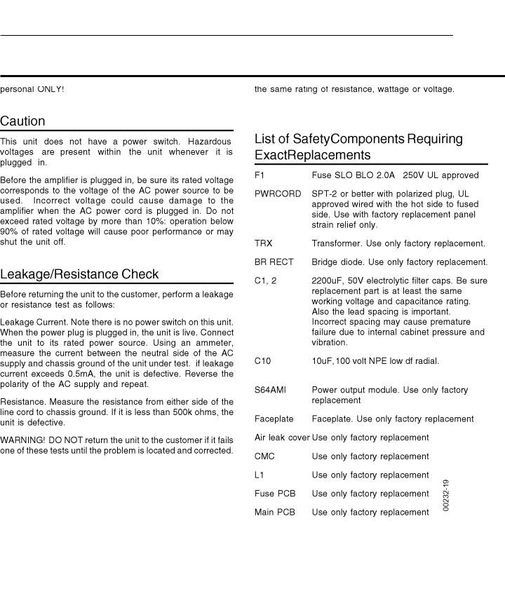
SAFETY INFORMATION
3
PB12
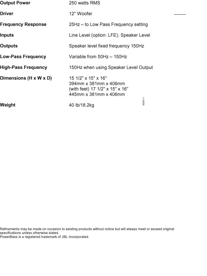
BASIC SPECIFICATIONS PB12 Subwoofer
4

PB12
DETAILED SPECIFICATIONS PB12 Subwoofer
5
PB12
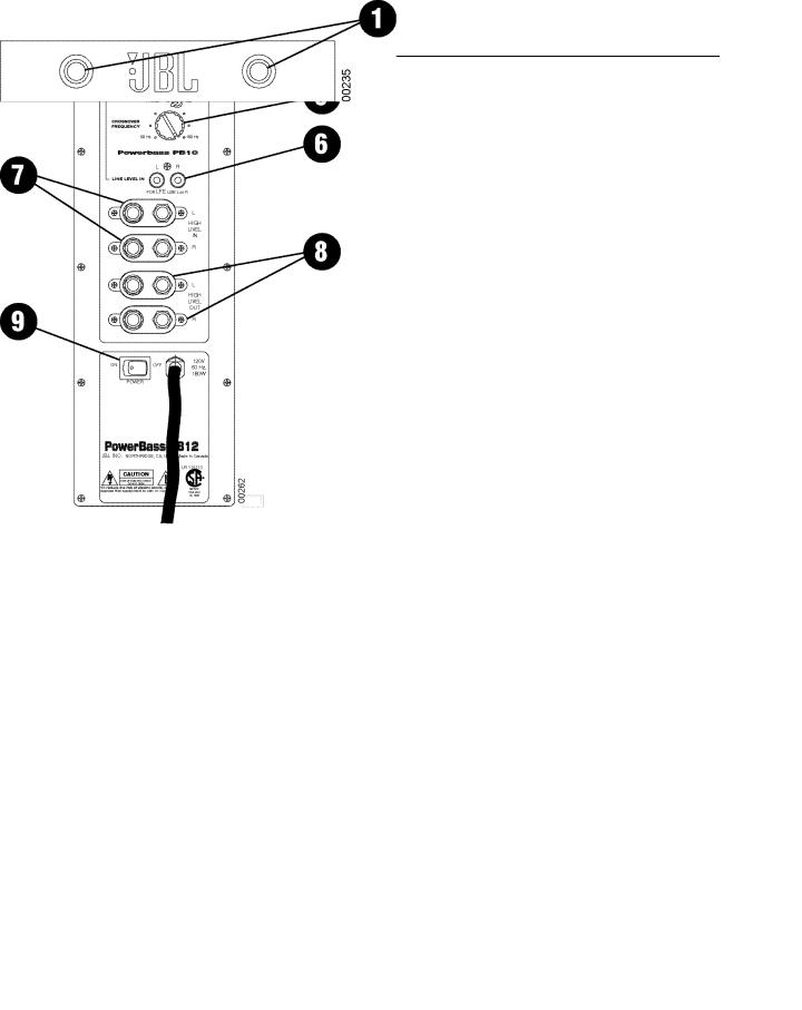
PB12 Subwoofer Controls and their Function
1. |
Power - These lights will be red when the unit is |
Front Panel |
|
plugged in and not receiving a signal; when the PB12 |
|
|
receives a signal, the lights will cycle to GREEN. If no |
|
|
signal is received after 10-15 minutes the lights will |
|
|
cycle back to RED (standby) until a signal is present |
|
|
again. |
|
2. |
Level Control - The subwoofer Level Control, PB12, |
|
|
(located on the rear panel) adjusts the volume of the |
|
|
subwoofer relative to the rest of the system. |
|
3. |
LFE/Normal Switch - Ordinarily placed in the Normal |
|
|
position - but switch to LFE when playing Dolby |
|
|
DigitaL, DTS or other digital surround modes - see |
|
|
page 9. |
|
4. |
Phase Switch - Changes the subwoofer’s output to |
|
|
be in phase or 180 degrees out of phase with the |
Rear Panel |
|
program material. |
5.Crossover Frequency - Sets the highest frequency the subwoofer will reproduce.
6.Line Input - Main Input connection to subwoofer (preferred).
7.Speaker In Jacks - Main Input connection to subwoofer when line level, subwoofer, or pre-amp output connectors are not available, or when a high pass filter (set at 150Hz) to main loudspeakers is desired through the Speaker Output Jacks.
8.Speaker Out Jacks - Connected to main loudspeakers when the Speaker Input Jacks are used.
9.Power Switch - Turns the PB12 on or off.
6
PB12
Speaker Connection
When we designed the PB10 and PB12 powered subwoofers, our goal was to offer the user the best possible performance combined with the most flexible and complete installation options. Please look over the following three
examples to determine which description best matches your system and follow the corresponding hookup instructions.
To use the binding-post speaker terminals with bare wire, unscrew the collar until
the hole through the centerpost is visible under the collar.
Insert the bare end of the wire through the hole in the post, then screw the collar back down until the connection is tight. The holes in the center of the collars are intended for banana-type connectors.
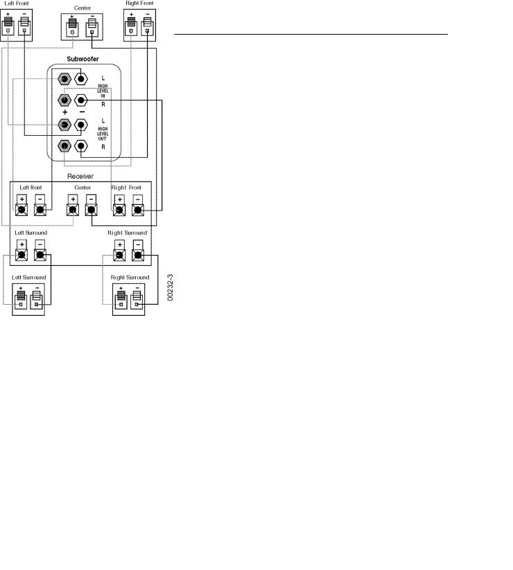
Dolby Pro Logic (Non-Digital)-Speaker Level
Use this installation method for Dolby Pro Logic applications (not Dolby Digital, DTS or other digital processing), where the receiver/processor does not have a subwoofer output or a volume-controlled preamp (line-) level output:
Connect your receiver or amplifier’s front left and right speaker terminals to the left and right terminals on the subwoofer that are marked “High Level In.” Connect the left and right terminals on the subwoofer that are marked “High Level Out” to the corresponding terminals on the
back of your front left and right speakers.
Connect your receiver or amplifier’s center, left and right surround-speaker terminals to the corresponding terminals on the back of your center, left and right surround speakers.
7

PB12
Dolby Pro Logic (Non-Digital)-Line Level
Use this installation method for Dolby Pro Logic applications (not Dolby Digital, DTS or other digital processing), where the receiver/processor is equipped with a subwoofer output or a volume-controlled preamp (line-) level output:
Use RCA-type patch cords to connect the line-level subwoofer outputs on your receiver or amplifier to the linelevel inputs on the subwoofer. IMPORTANT: Make sure that the LFE toggle switch on the subwoofer is in the “Normal” position. Do not use the “LFE”
position with Dolby Pro Logiconly processors.
Note: If your receiver or amplifier only has one subwoofer output jack, then you may connect the subwoofer output on your receiver/preamplifier to either the left or right line-level input on the subwoofer. It makes no difference which jack you choose.
Connect each speaker to the corresponding speaker terminals on your receiver or amplifier.
Make sure your receiver or processor is configured correctly; Make sure that the subwoofer is configured as “On.”
Note for advanced users: If your receiver/processor has a built-in low-pass crossover filter for the subwoofer output, then the LFE switch should be set to the “LFE” position to bypass the subwoofer’s internal crossover.
8

PB12
Dolby Digital or DTS (or Other Digital Surround Mode) Connection
Use this installation method for Dolby Digital, DTS or other digital surround processors:
IMPORTANT: Make sure that the LFE toggle switch on the subwoofer is in the “LFE” position. Use the line-level input jacks for the lowFrequency Effects channel. Connect these jacks to the LFE output or subwoofer output on your receiver or amplifier.
Note: If your receiver or amplifier only has one subwoofer output jack, then
you may connect the subwoofer output on your receiver/preamplifier to either the left or right line-level input on the subwoofer. It makes no difference which jack you choose.
Connect each speaker to the corresponding speaker terminals on your receiver or amplifier.
Make sure that you have configured your surroundsound processor for “Subwoofer On”or “LFE On.”
The front left, front right, center and rear speakers should be set to “Small” or “Large” depending on their size and frequency response. Consult your receiver’s or processor’s owner’s manual.
9
 Loading...