


MPC Series Power Amplifiers
Owner’s Manual
TD-000074-00
TD-000074-00 21
Rev. C

Table of Contents |
|
Table of Contents ................................................................................................................................................................................... |
1 |
Warning notices ..................................................................................................................................................................................... |
2 |
Speaker Output Shock Hazard ......................................................................................................................................................... |
2 |
Rack Mounting Precautions ............................................................................................................................................................ |
2 |
Lifting Precautions ........................................................................................................................................................................... |
2 |
Description ............................................................................................................................................................................................ |
3 |
Inputs ..................................................................................................................................................................................................... |
5 |
Outputs .................................................................................................................................................................................................. |
6 |
Driving Distributed Lines ..................................................................................................................................................................... |
7 |
Low-Impedance and Distributed Speakers on T-Version Amplifiers .............................................................................................. |
7 |
Using Multiple Distributed Line Voltages ...................................................................................................................................... |
10 |
Bridged Mono Mode ............................................................................................................................................................................ |
10 |
MPC200 & 200T Bridged Mono Configuration .............................................................................................................................. |
11 |
MPC300, 300T, 600 & 600T Bridged Mono Configuration ............................................................................................................. |
11 |
Bridged Mono Speaker Connection ................................................................................................................................................ |
11 |
Low Impedance Bridged Mono ...................................................................................................................................................... |
12 |
High Impedance Bridged Mono ..................................................................................................................................................... |
12 |
Parallel Mono Configuration ................................................................................................................................................................ |
12 |
Controls ................................................................................................................................................................................................ |
13 |
Displays ................................................................................................................................................................................................ |
13 |
AC Power .............................................................................................................................................................................................. |
14 |
Operation .............................................................................................................................................................................................. |
14 |
MPC200 & 200T .............................................................................................................................................................................. |
14 |
MPC300, 300T, 600, & 600T ............................................................................................................................................................ |
14 |
Protection Circuits ................................................................................................................................................................................ |
14 |
Glossary ................................................................................................................................................................................................ |
15 |
Specifications ........................................................................................................................................................................................ |
16 |
Power Consumption ............................................................................................................................................................................. |
17 |
Heat Emission ...................................................................................................................................................................................... |
18 |
Troubleshooting ................................................................................................................................................................................... |
19 |
For Further Assistance ......................................................................................................................................................................... |
20 |
WITHIN THE UNITED STATES: .............................................................................................................................................. |
20 |
General Information or Technical Assistance ................................................................................................................................. |
20 |
Repairs ............................................................................................................................................................................................. |
20 |
OUTSIDE THE UNITED STATES: ............................................................................................................................................ |
20 |
1
Cautions
Rack Mounting Precautions
To avoid damage to the amplifier mounting ears and/or rack rails, the amplifier must be supported at all four corners when used in portable racks.
Consult JBL Service Dept for availability of Rear Support Brackets.
Lifting Precautions
In order to safely move or install the amplifier, it is recommended that two persons share the weight when lifting and positioning the unit.
Sicherheitsvorschriften
Sicherheitsvorschriften für den Einbau in ein Gestell
Um Schäden auf den Befestigungsleisten des Verstärkers und/oder den Gestellschienen zu vermeiden, muß der Verstärker beim Einbau in ein tragbares Gestell an allen vier Ecken gestützt werden.
Erkundigen Sie sich bei der JBL-Kundendienstabteilung nach Stützen für die Rückseite des Verstärkers.
Sicherheitsvorschriften beim Hochheben
Um den Verstärker sicher zu verschieben oder einzubauen, wird empfohlen, das Gewicht des Verstärkers beim Hochheben und Verschieben gleichmäßig auf zwei Personen zu verteilen.
CAUTION
TO AVOID ELECTRIC SHOCK, DO NOT INSERT FINGERS OR OBJECTS INTO ANY OPENINGS IN THE CHASSIS.
VORSICHT
UM ELEKTRISCHEN SCHLAG ZU VERMEIDEN, KEINE FINGERN ODER GEGENSTÄNDE IN ÖFFNUNGEN DES GEHÄUSES STECKEN.
Warning notices
Speaker Output Shock Hazard
A MPC amplifier is capable of producing hazardous output voltages. To avoid electrical shock, make sure the cover is in place over the output terminals, and do not touch any exposed speaker wiring while the amplifier is operating.
Rack Mounting Precautions
To minimize twisting stress of the front mounting ears, the amplifier’s internally mounted output transformers are located close to the front panel. Nevertheless, when rack mounting any MPC amplifier, make sure it is well supported at all four corners to avoid damage to either the amplifier mounting ears or to the mounting rails. Rear support brackets are available.
Lifting Precautions
In order to safely move or install the amplifier, it is recommended that two persons share the weight when lifting and positioning the unit.
2

Description
The MPC Series from JBL is a line of professional power amplifiers specifically designed for contracting applications. There are six models, each with two independent channels. Each model in the MPC Series line is available in a “T” version for driving either 200V, 140V, 100V, 70V, 50V, or 25V “constant voltage” lines and in a “non-T” versions for driving loudspeaker systems with impedances as low as 2 ohms. (See section on bridging for information about 200V, 140V, and 50V drive capabilities).
Power Capabilities—The table below lists the power ratings under various load conditions:
Model |
4Ω1 |
2Ω2 |
100 Volts |
70 Volts |
25 Volts |
MPC200 |
225 W × 2 |
350 W × 2 |
|
|
|
|
|
|
|
|
|
MPC200T |
225 W × 2 |
350 W × 2 |
175 W × 2 3 |
175 W × 2 3 |
150 W × 2 3 |
MPC300 |
300 W × 2 |
450 W × 2 |
|
|
|
|
|
|
|
|
|
MPC300T |
300 W × 2 |
450 W × 2 |
250 W × 2 4 |
250 W × 2 4 |
200 W × 2 4 |
MPC600 |
600 W × 2 |
900 W × 2 |
|
|
|
|
|
|
|
|
|
MPC600T |
600 W × 2 |
900 W × 2 |
500 W × 2 4 |
500 W × 2 4 |
400 W × 2 4 |
1
2
3
4
FTC watts per channel, 20 Hz–20 kHz, 0.1% THD EIA watts per channel, 1 kHz, 1% THD
Watts per channel, band limited for 50 Hz–15 kHz response, 0.25% THD Watts per channel, band limited for 45 Hz–15 kHz response, 0.25% THD
Channel Separation—Each channel has its own power transformer secondary to provide maximum audio separation (minimum sound leakage) between the two channels, minimizing interaction that can otherwise occur on amplifiers with a common power supply.
High Efficiency—The MPC200, 200T, 300 & 300T utilize complementary Class AB linear output circuitry. For improved efficiency, the MPC600 and 600T utilize Class H step-linear complementary output circuitry using multi-rail power supplies.
High Cooling Capacity—Every MPC amplifier features a large diameter two-speed fan and massive extruded aluminum heat sinks. The output devices couple directly to the heat sink. This provides better cooling of the output devices while eliminating problematic insulating wafers that are an integral part of most other amplifier designs. Forced air cooling in a back- to-front direction provides for more effective cooling, preventing problems that otherwise occur from a continual heat build-up inside the equipment rack, which occurs in amplifiers with front-to-back or side-to-side flow schemes. These design factors allow the MPC amplifiers to work in high duty-cycle instances when many other professional amplifiers cannot.
Weight Balance—The power transformers, as well as the output transformers on the T models, are mounted in the front of the amplifier chassis, as close to the front mounting rails as possible. This keeps the unit’s center of gravity forward to minimize the twisting force on the front mounting ears.
Rail Support—The amplifier should be supported at all four corners, especially if it is in a portable rack. The flow-through cooling scheme allows you to rack-mount the amplifiers on top of the other, with no clearance necessary in between. This mounting technique also helps support the weight of the upper amplifiers. In permanent fixed installations, the rear of the amplifiers can receive physical support by installing the amplifiers at the bottom of the equipment rack. Make sure that the direct weight of the back of the amplifier is supported from the bottom of the rack.
Dimensions—
a) Height—The MPC200 and 200T are 2 rack spaces high. The MPC300, 300T, 600 and 600T are 3 rack spaces high.
3

12 |
1 |
4 |
5 |
5 |
4 |
12 |
MPC600T front panel (MPC300, 300T, and 600 are similar)
MPC200T front panel (MPC200 is similar)
|
3 |
|
2 |
2 |
3 |
|
|
|
12 |
1 |
2 |
4 |
2 |
|
|
|
12 |
13 |
6 |
|
|
|
9 |
10 |
11 |
13 |
CH2 |
12 |
10 |
8 |
|
CH2 |
INPUT |
CH1 |
|
|
12 |
10 |
8 |
CH1 |
14 |
|
6 |
|
|
|
6 |
|||||||
|
|
|
|
GROUND |
|
STER EO |
14 |
|
|
||||
18 |
|
|
|
4 |
|
|
18 |
|
|
4 |
|||
|
|
|
|
|
|
|
|
|
|
||||
24 |
|
|
0 |
2 |
|
|
|
|
|
24 |
|
0 |
2 |
|
|
-dB |
|
|
|
|
|
|
|
-dB |
|
||
|
|
LEVEL |
|
|
INPUT |
|
PARALLEL |
BRIDGE |
|
LEVEL |
|
||
CH1 LOW IMPEDANCE |
AUDIO TRANSFORMER |
CH1 |
|
DIR. OUTPUT |
0 |
70 100 ISOL.OUTPUT |
|
BRIDGE |
70V |
25V |
|
100V |
|||
MONO |
|||
|
|
||
CH2 LOW IMPEDANCE |
AUDIO TRANSFORMER |
CH2 |
|
DIR. OUTPUT |
0 |
70 100 ISOL.OUTPUT |
|
BRIDGE |
70V |
25V |
|
100V |
|||
MONO |
|||
|
|
||
7 |
8 |
14 7 MPC300T and 600T rear panel |
10 |
11 |
|
13 |
|
6 |
9 |
10 |
13 |
CH2
OUTPUT
CH1
OUTPUT
BRIDGE |
BRIDGE |
MONO |
MONO |
CH2 |
12 |
10 |
8 |
|
CH2 |
INPUT |
CH1 |
|
|
12 |
10 |
8 |
CH1 |
14 |
|
6 |
|
|
|
6 |
|||||||
|
|
|
|
GROUND |
|
STEREO |
14 |
|
|
||||
18 |
|
|
|
4 |
|
|
18 |
|
|
4 |
|||
|
|
|
|
|
|
|
|
|
|
||||
24 |
|
|
0 |
2 |
|
|
|
|
|
24 |
|
0 |
2 |
|
|
-dB |
|
|
|
|
|
|
|
-dB |
|
||
|
|
LEVEL |
|
|
INPUT |
|
PARALLEL |
BRIDGE |
|
LEVEL |
|
||
1Power Switch
2Power Indicators (Ch. 1 & Ch. 2)
3Signal Indicators (Ch. 1 & Ch. 2)
4Clip Indicators (Ch. 1 & Ch. 2)
5Protect Indicators (Ch. 1 & Ch. 2)
6Accessory Slot Cover
7Gain Control
8Detachable Input Header Block
9Cooling Fan
10Shrouded Output Connector (Direct Outputs)
11Shrouded Output Connector (Audio Transformer Outputs)
12Mounting Holes for Optional Handles
13Rear Support Ears
14Parallel/Stereo/Bridge Switch
7 |
8 |
14 |
7 |
MPC300 and 600 rear panel |
|
|
|
|
|
|
13 |
|
|
|
9 |
10 |
11 |
|
10 |
11 |
13 |
|
|
|
|
CH2 |
LOW IMPEDANCE AUDIO TRANSFORMER CH2 |
CH1 |
LOW IMPEDANCE AUDIO TRANSFORMER CH1 |
|||
|
|
|
|
DIR. OUTPUT |
0 70 100 ISOL.OUTPUT |
DIR. OUTPUT |
0 70 100 ISOL.OUTPUT |
|||
|
CH2 |
|
|
|
|
|
|
CH1 |
|
|
|
|
|
12 |
10 |
8 |
|
CH2 |
INPUT |
CH1 |
12 |
10 |
8 |
|
|
|
|
|
6 |
|
|
|
|
|
|||||||
14 |
|
|
|
GROUND |
|
14 |
|
6 |
|
70V 25V |
|
70V 25V |
|
18 |
|
|
4 |
|
|
|
18 |
|
4 |
BRIDGE |
100V |
BRIDGE |
100V |
24 |
|
|
2 |
|
|
|
24 |
|
2 |
MONO |
|
MONO |
|
|
0 |
|
|
|
|
|
|
|
|
||||
|
-dB |
|
|
|
|
|
-dB |
0 |
|
|
|
|
|
LEVEL |
INPUT |
|
LEVEL |
|
|
||
7 |
|
|
8 |
7 |
|
MPC200T rear panel |
|
|
13 |
|
|
|
|
|
9 |
10 |
13 |
|
|
|
|
|
|
|
CH2 |
CH1 |
|
|
|
|
|
|
|
OUTPUT |
OUTPUT |
|
CH2 |
|
|
|
CH1 |
|
|
|
12 |
10 |
8 |
CH2 INPUT CH1 |
12 |
10 |
8 |
|
|
|
|
|
|
|||||
14 |
|
6 |
GROUND |
14 |
|
6 |
BRIDGE |
BRIDGE |
18 |
|
4 |
18 |
|
4 |
|||
|
|
|
MONO |
MONO |
||||
24 |
|
2 |
|
24 |
|
2 |
|
|
|
-dB |
0 |
|
|
-dB 0 |
|
|
|
|
LEVEL |
INPUT |
|
LEVEL |
|
|
||
7 |
8 |
7 |
MPC200 rear panel |
4
b) Depth—The amplifiers require a rack depth of 45.7 cm (18 in) to clear the rear support ears. The rear panel is 42.9 cm (16.9 in) behind the plane of the front mounting rails, allowing some room for routing of wires.
Stability, Reliability and Protection—The MPC Series is engineered for stability and exceptional reliability, with protection for open or short circuits and mismatched (underimpedance) loads. Protection is also built-in for ultrasonic, infrasonic (subsonic) and RF. To protect the loudspeakers the outputs mute during turn-on and turn-off and also in the event of a DC load fault. (The MPC200 and 200T are AC coupled and cannot pass DC to the load; thus DC fault muting is not required on these models.) See section on Protection Circuits for additional information.
All protection circuitry automatically resets to normal when conditions assure safe operation.
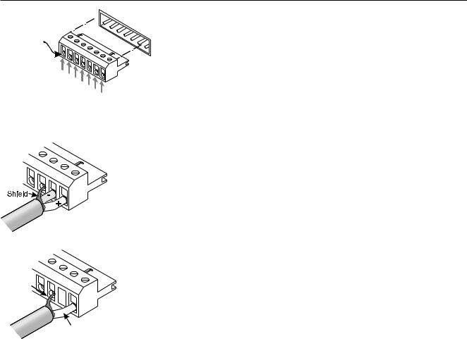
Inputs
Loosen screw,  insert wire here,
then tighten screw.
Channel 1+
Channel 1-
Ground
Ground
Ground
Channel 2-
Channel 2+
MPC amplifiers feature balanced inputs, connected via a Euro-style 7-terminal detachable header.
Wire jumper between input and ground
Shield

Signal conductor
Balanced Connection—Attach as shown. Connect the (+) wire, (-) wire and ground wire to terminal pins as marked.
Unbalanced Connection—Attach input signal wires as shown. Use the non-inverting (+) input and the ground terminals of the header, and also connect a wire jumper between the inverting (-) input and the ground terminal. The wire jumper will prevent a reduction in gain caused by a floating unbalanced input.
Input Sensitivities—Audio signals of the following levels will produce full rated output power at 8 ohms with the volume control turned up full.
MPC200 & 200T 0.96 Volts
MPC300 & 300T 1.02 Volts
MPC600 & 600T 1.00 Volts
5
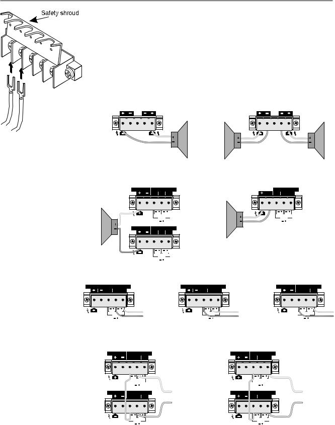
Outputs
Covered barrier strips located on the rear panel allow safe, shockproof speaker cable connections to the amplifier outputs. See the diagrams for details on connecting speakers and/or distributed (25V, 70V, 100, 140V, and 200V) lines. Insulated connectors of the type shown are recommended. Always make sure the amplifier is turned off before you change any output connections or before lifting the safety shroud.
For driving 140V or 200V distributed lines, the amplifier must be set into bridged mono mode. See “Bridged Mono Mode” section later in this manual for information about this mode.
Lift safety shroud. Loosen screw terminals. Insert wire connectors under screws.
Tighten screw terminals. Lower safety shroud.
Output connection for MPC, bridged mono mode.
CH2 |
|
CH1 |
|
OUTPUT |
|
OUTPUT |
|
BRIDGE |
BRIDGE |
16Ω |
|
8Ω |
|||
MONO |
MONO |
||
|
|
4Ω |
Output connection for MPC, parallel or stereo mode.
|
CH2 |
|
CH1 |
|
|
OUTPUT |
|
OUTPUT |
|
8Ω |
BRIDGE |
BRIDGE |
8Ω |
|
4Ω |
4Ω |
|||
MONO |
MONO |
|||
2Ω |
|
|
2Ω |
Output connection for MPC “T” models, bridged mono mode.
|
CH1 |
LOW IMPEDANCE |
AUDIO TRANSFORMER |
CH1 |
|
DIR. OUTPUT |
ISOL.OUTPUT |
||
|
|
BRIDGE |
70V 25V |
|
16Ω |
|
100V |
|
|
|
MONO |
|
||
|
|
|
||
|
|
|
|
|
8Ω |
CH2 |
LOW IMPEDANCE |
AUDIO TRANSFORMER |
CH2 |
4Ω |
DIR. OUTPUT |
ISOL.OUTPUT |
||
Output connection for MPC “T” models, direct low impedance.
CH1 |
|
AUDIO TRANSFORMER CH1 |
||
LOW IMPEDANCE |
||||
|
||||
DIR. OUTPUT |
|
|
ISOL.OUTPUT |
|
|
||||
8Ω |
BRIDGE |
70V |
25V |
|
4Ω |
100V |
|||
MONO |
||||
|
|
|||
2Ω |
|
|
|
|
BRIDGE |
70V 25V |
100V |
|
MONO |
|
Output connection for “T” models, |
Output connection for “T” models, |
Output connection for “T” models, |
|||||||||
|
25 volt line. |
|
|
50 volt line. |
|
|
100 volt line. |
|
|||
CH1 |
LOW IMPEDANCE |
AUDIO TRANSFORMER |
CH1 |
CH1 |
LOW IMPEDANCE |
AUDIO TRANSFORMER |
CH1 |
CH1 |
LOW IMPEDANCE |
AUDIO TRANSFORMER |
CH1 |
DIR. OUTPUT |
ISOL.OUTPUT |
DIR. OUTPUT |
ISOL.OUTPUT |
DIR. OUTPUT |
ISOL.OUTPUT |
||||||
|
BRIDGE |
70V 25V |
|
|
BRIDGE |
70V 25V |
|
|
BRIDGE |
70V 25V |
|
|
100V |
|
|
100V |
|
|
100V |
|
|||
|
MONO |
|
|
MONO |
|
|
MONO |
|
|||
|
|
|
|
|
|
|
|
|
|||
Output connections for “T” models, bridged mono mode, 140 volt line
Output connections for “T” models, bridged mono mode, 200 volt line
CH1 |
LOW IMPEDANCE |
AUDIO TRANSFORMER |
CH1 |
|
CH1 |
LOW IMPEDANCE |
AUDIO TRANSFORMER |
CH1 |
|
||
DIR. OUTPUT |
|
ISOL.OUTPUT |
|
DIR. OUTPUT |
|
ISOL.OUTPUT |
|
||||
|
BRIDGE |
70V |
25V |
|
|
|
BRIDGE |
70V |
25V |
|
|
|
100V |
|
|
|
100V |
|
|
||||
|
MONO |
|
|
|
MONO |
|
|
||||
|
|
|
|
|
|
|
|
|
|
||
CH2 |
LOW IMPEDANCE |
AUDIO TRANSFORMER |
CH2 |
TO 140V LINE |
CH2 |
LOW IMPEDANCE |
AUDIO TRANSFORMER |
CH2 |
TO 200V LINE |
||
DIR. OUTPUT |
|
ISOL.OUTPUT |
DIR. OUTPUT |
|
ISOL.OUTPUT |
||||||
|
BRIDGE |
70V |
25V |
|
|
|
BRIDGE |
70V |
25V |
|
|
|
100V |
|
|
|
100V |
|
|
||||
|
MONO |
|
|
|
|
|
MONO |
|
|
|
|
6
 Loading...