

X + 0 + Y2 0M
HZ
OWNER’S GUIDE
PRODUCT LINE:
SCS178 (230V)
DESIGN GOAL: Bring the thrill of live performance and movie sound to the
home environment by calling on JBL’s professional engineering leadership.
SATELLITE TYPE:Titanium-laminate-dome tweeter, reflex-loaded enclosure
SUBWOOFER TYPE: Bass-reflex enclosure
PORT DESIGN: FreeFlow™ flared
PROFESSIONAL REFERENCE: Cinema Loudspeaker Series
®
MODEL
NUMBER:
2
READ THIS! Important Safety Precautions!
General:
1. Unpacking: Check the product carefully. If
it has been damaged in transit, report the damage immediately by calling your dealer
and/or the shipping company that delivered
it.
2. Connections: Whenever changing, connecting or disconnecting signal or power
cables etc., always turn off all equipment.
This prevents transients from entering the
equipment and prevents electrical energy
from reaching you. Keep all connections out
of the reach of children. Before moving the
unit, be certain to disconnect any interconnection cords with other components, and
make certain that you disconnect any powered units from the AC outlet.
3. Read Instructions. All the safety and
operating instructions should be read before
the product is operated.
4. Retain Instructions. The safety and operating instructions should be retained for
future reference.
5. Heed Warnings. All warnings on the product and in the operating instructions should
be adhered to.
6. Follow Instructions. All operating and use
instructions should be followed.
7. Water and Moisture. The product should
not be used near water – for example, near a
bathtub, washbowl, kitchen sink, laundry tub,
in a wet basement, or near a swimming pool,
and the like.
8. Accessories. To ensure proper operation
and to avoid the potential for safety hazards,
place the unit on a firm and level surface.
When placing the unit on a shelf, be certain
that the shelf and any mounting hardware
can support the product’s weight. Do not
place this product on an unstable cart, stand,
tripod, bracket, or table. The product may fall,
causing serious injury to a child or adult, and
serious damage to the product. Use only with
a cart, stand, tripod, bracket, or table recommended by the manufacturer, or sold with the
product. Any mounting of the product should
follow the manufacturer’s instructions, and
should use a mounting accessory recommended by the manufacturer.
9. Wall or Ceiling Mounting. The product
should be mounted on a wall or ceiling only
when and as recommended by the manufacturer.
10. Cleaning. Unplug this product from the
wall outlet before cleaning. Do not use liquid
cleaners or aerosol cleaners. Use a damp
cloth for cleaning.
11. Attachments. Do not use attachments not
recommended by the product manufacturer,
as they may cause hazards.
12. Replacement Parts. When replacement
parts are required, be sure the service technician has used replacement parts specified
by the manufacturer or that have the same
characteristics as the original part.
Unauthorized substitutions may result in fire,
electric shock or other hazards.
13. Safety Check. Upon completion of any
service or repairs to this product, ask the
service technician to perform safety checks
to determine that the product is in proper
operating condition.
14. Feet/Spikes. When positioning, or moving
this product ensure that is lifted rather than
dragged across any floor/mounting surface.
This will avoid any damage to the floor/mounting surface. Attention! Products and/or
product feet constructed of rubber or plastics
may, in seldom cases, react chemically and
discolor treated or non-treated wooden surfaces if positioned without protection.
15. Warranty: The following conditions may
result in a void product warranty:
a. the manufacturers serial number is remo-
ved or forged.
b. if repairs and/or modifications and/or other
treatments/tunings have been carried out
by non-authorized personnel or
accessories/supplements are attached,
which are not approved by
manufacturer/importer.
16. Warranty: The following items are not
covered by the product warranty:
a. Damage caused by inappropriate handling
despite clear instructions provided in the
owners manual.
b. Damage to mechanical parts (such as
record-/playback heads, moving rubber
and plastic parts and fuses) as well as
results of normal wear and tear.
c. Damage caused by external action or
influence.
d. Damage caused by miss-use by user.
e. Damage caused by excessive electrical
mains supply voltage or lightning strike.
f. Damage caused by fire, water or smoke.
g. Damage known to buyer prior to purchase.
h. Damage caused by professional employ-
ment of home entertainment products (e.g.
for catering trade, restaurants, public ad-
dress or infinite loop announcement use
etc.)
17. Specifications: All product specifications/features are subject to change without
notification.
Passive Products:
18. Amplifiers: Amplifiers used to drive these
units must deliver a sufficient output power. A
lack of output power may lead to amplifierclipping, which causes damage not covered
by guarantee.
Active (Powered) Products:
19. Ventilation. Slots and openings in the
cabinet are provided for ventilation and to
ensure reliable operation of the product and
to protect it from overheating, and these
openings must not be blocked or covered.
The openings should never be blocked by
placing the product on a bed, sofa, rug, or
other similar surface. This product should not
be placed in a built-in installation such as a
bookcase or rack unless proper ventilation is
provided or the manufacturer’s instructions
have been adhered to.
Make certain that the proper space (more
than 10cm) is provided both above and below
the unit for ventilation. If the amplifier will be
installed in a cabinet or other enclosed area,
make certain that there is sufficient air
movement within the cabinet, with means
provided for hot air to exit and for cool air to
be brought in.
Do not obstruct the ventilation slots on the
top of the unit or place objects directly over
them. Remember, power amplifiers generate
heat, and the heatsink fins and ventilation
slots that form part of the cabinet are specially designed to remove this heat. Placing
other electronic equipment near these heatdissipation systems may possibly affect the
long term reliability of both your amplifier and
the objects placed above it.
Do not place CDs, record jackets, owner’s
manuals or other paper on top of or beneath
the unit or in between products containing
amplifiers in a stack. This will block the air
flow, causing degraded performance and a
possible fire hazard.
20. Power Sources. This product should be
operated only from the type of power source
indicated on the marking label. If you are not
sure of the type of power supply to your
home, consult your product dealer or local
power company. For products intended to
operate from battery power, or other sources,
refer to the operating instructions.
21. Grounding or Polarization. This product
may be equipped with a polarized alternatingcurrent line plug (a plug having one blade
wider than the other). This plug will fit into the
power outlet only one way. This is a safety
feature. If you are unable to insert the plug
fully into the outlet, try reversing the plug. If
the plug should still fail to fit, contact your
electrician to replace your obsolete outlet.
Do not defeat the safety purpose of the
polarized plug.
22. Power-Cord Protection. Power-supply
cords should be routed so that they are not
likely to be walked on or pinched by items
placed upon or against them, paying particular attention to cords at plugs, convenience receptacles, and the point where
they exit from the product. To avoid safety
hazards, use only the power cord supplied
with your unit. If a replacement cord is used,
make certain that it is of a similar gauge. We
do not recommend using extension cords
with this product. As with all electrical
devices, do not run power cords under rugs
or carpets or place heavy objects on power
cords. Damaged power cords should be
replaced immediately, by a qualified service
technician, with cords meeting factory
specifications. When disconnecting the
power cord from an AC outlet, always pull the
plug; never pull the cord.
CAUTION
RISK OF ELECTRIC SHOCK
DO NOT OPEN
CAUTION: To prevent electric shock,
do not remove the grounding plug
on the power cord, or use any plug
or extension cord that does not have
a grounding plug provided.
Make certain that the
AC outlet is properly grounded.
Do not use an adapter plug
with this product.
The lightning flash with arrowhead
symbol, within an equilateral triangle, is
intended to alert the user to the
presence of uninsulated “dangerous
voltage” within the product’s enclosure
that may be of sufficient magnitude to
constitute a risk of electric shock to
persons.
The exclamation point within an
equilateral triangle is intended to alert
the user to the presence of important
operating and maintenance (servicing)
instructions in the literature
accompanying the appliance.
3
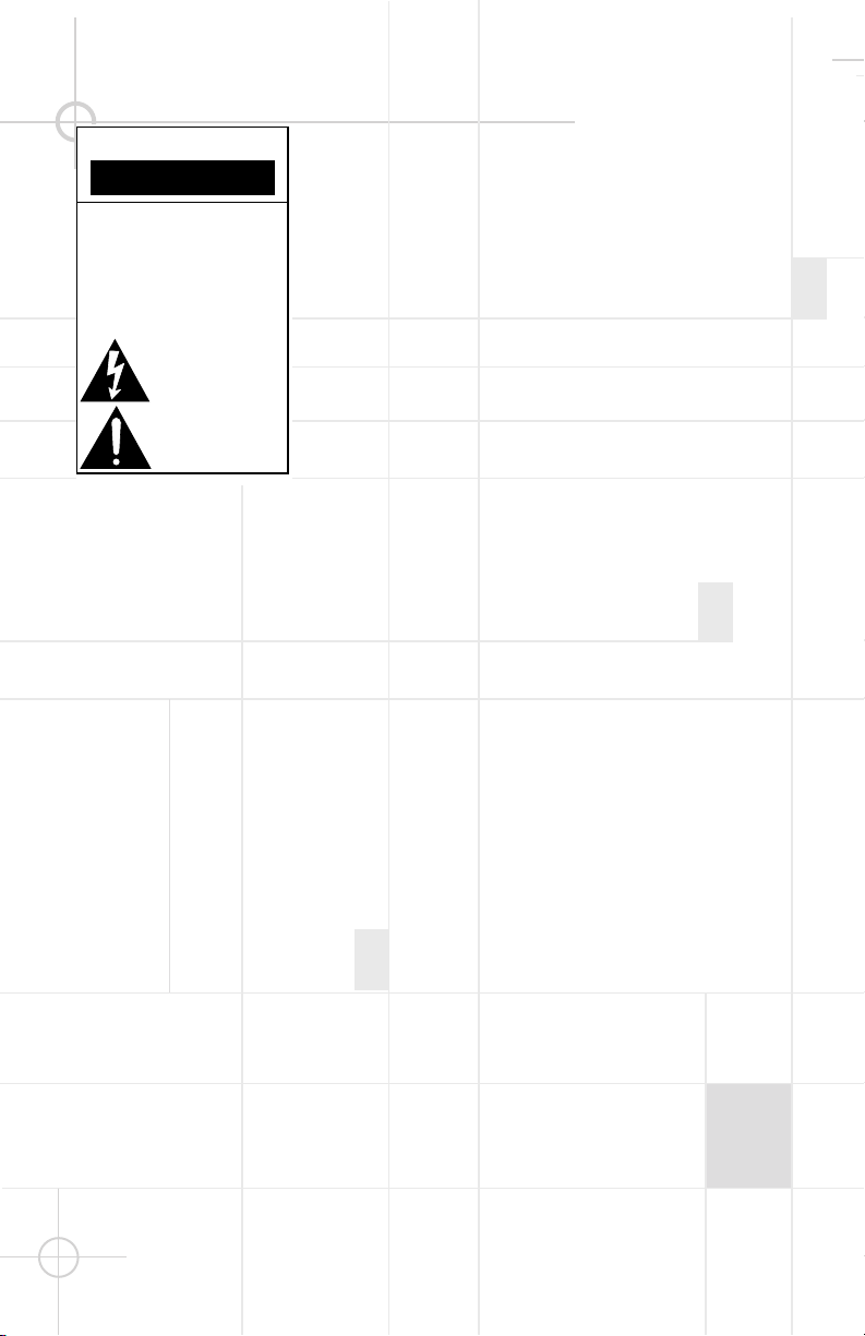
INCLUDED
Four satellites for left/right
front and surrounds.
One center channel speaker. Powered subwoofer.
For more than 50 years, JBL
has been involved in every
aspect of music and film
recording and reproduction,
from live performances to the
recordings you play in your
home, car or office.
We’re confident that the JBL
system you have chosen will
provide every note of enjoment
that you expected – and that
when you think about
purchasing additional audio
equipment for your home, car
or office, you will once again
choose JBL.
JBL Consumer Products
THANK YOU FOR CHOOSING JBL
Two 6.1-meter (20-foot) speaker
cables for connection from
receiver to subwoofer.
Two 4.6-meter (15-foot) speaker
cables for connection from
subwoofer to front speakers.
Three 12.2-meter (40-foot)
speaker cables for connection
from receiver to left and right
rear satellites and center
speaker.
23. Non-use Periods. The power cord of
the product should be unplugged from the
outlet when left unused for long periods of
time.
24. Lightning. For added protection for this
product during a lightning storm, or when it
is left unattended and unused for long
periods of time, unplug it from the wall
outlet and disconnect the antenna or cable
system. This will prevent damage to the
product due to lightning and power-line
surges.
25. Overloading. Do not overload wall outlets, extension cords, or integral convenience receptacles, as this can result in a
risk of fire or electric shock.
26. Damage Requiring Service. Unplug this
product from the wall outlet and refer
servicing to qualified service personnel
under the following conditions:
a. The power-supply cord or the plug has
been damaged; or
b. Objects have fallen, or liquid has been
spilled into, the product; or
c. The product has been exposed to rain or
water; or
d. The product does not operate normally
when following the operating
instructions. Adjust only those controls
that are covered by the operating
instructions, as an improper adjustment
of other controls may result in damage
and will often require extensive work by
a qualified technician to restore the
product to its normal operation; or
e. The product has been dropped, or the
enclosure damaged; or
f. The product does not appear to operate
normally or exhibits a marked change in
performance.
27. Servicing. Do not attempt to service
this product yourself, as opening or
removing covers may expose you to
dangerous voltage or other hazards. Refer
all servicing to qualified service personnel.
28. Object and Liquid Entry. Never push
objects of any kind into this product
through openings, as they may touch
dangerous voltage points or short-out
parts that could result in a fire or electric
shock. Never spill liquid of any kind on the
product. The apparatus shall not be
exposed to dripping or splashing and no
objects filled with liquids, such as vases,
shall be placed on the apparatus.
29. Heat. The product should be situated
away from heat sources such as radiators,
heat registers, stoves or other products
(including amplifiers) that produce heat.
Avoid installation in extremely hot or cold
locations, in an area that is exposed to
direct sunlight or near heating equipment.
When positioning the product in its final
location, make certain that it has adequate
ventilation on all sides, as well as on the
top and bottom.
4
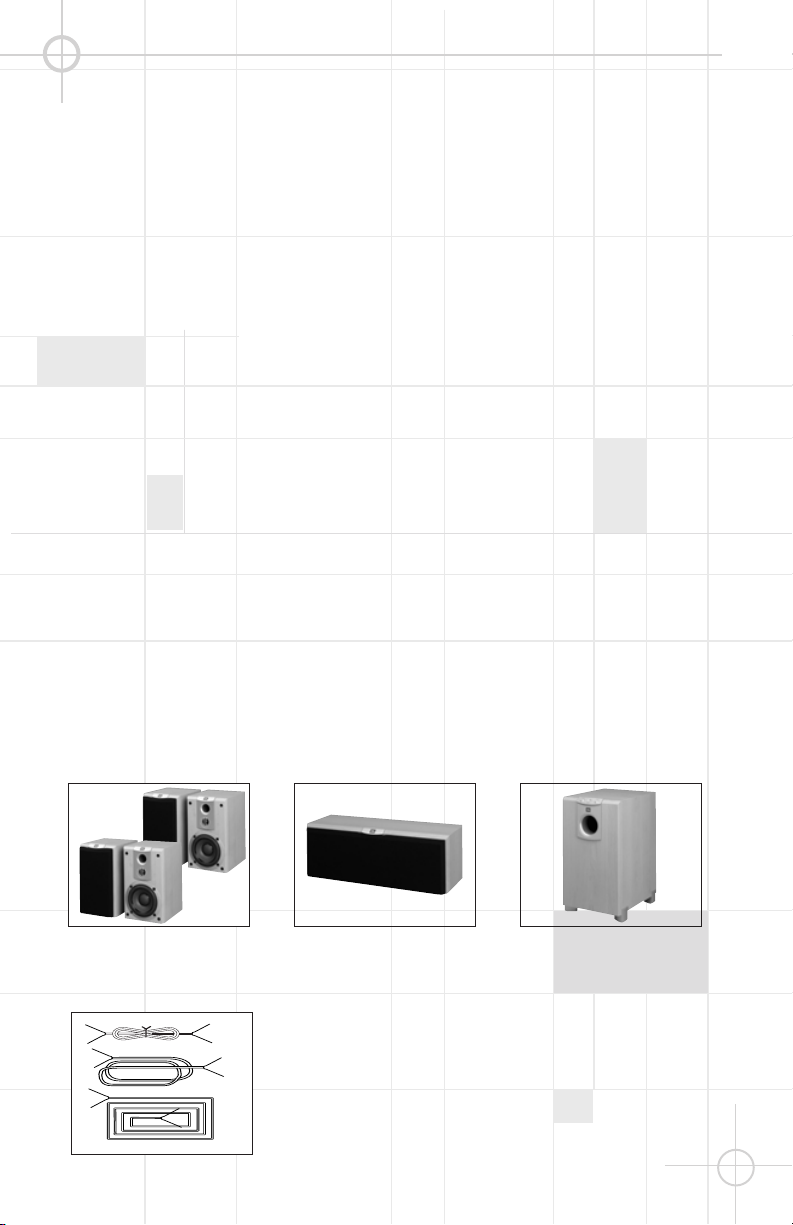
150-180 cm
0 – 0.6m (0 – 2 ft.)
Subwoofer
Surround Speakers
Front Speakers
The front speakers should be
placed the same distance from
each other as they are from the
listening position. They should
be placed at about the same
height from the floor as the
listeners’ ears will be, or they
may be angled toward the
listeners.
The center channel speaker
should be placed slightly
behind the front left and right
speakers, and no more than
two feet above or below the
tweeters of the left and right
speakers. It is often convenient
to set the center speaker on top
of the television set, as shown
in the drawing.
The two surround speakers
should be placed slightly
behind the listening position
and, ideally, should face each
other and be at a level higher
than the listeners’ ears. If that
is not possible, they may be
placed on a wall behind the
listening position, facing forward. The surround speakers
should not call attention to
themselves. Experiment with
their placement until you hear a
diffuse, ambient sound
accompanying the main
program material heard in the
front speakers.
The low-frequency material
reproduced by the subwoofer is
mostly omnidirectional, and this
speaker may be placed in a
convenient location in the
room. However, the best
reproduction of bass will be
heard when the subwoofer is
placed in a corner along the
same wall as the front
speakers. Experiment with
subwoofer placement by
temporarily placing the
subwoofer in the listening
position and moving around the
room until the bass
reproduction is best. Place the
subwoofer in that location.
Center Channel Speaker
SPEAKER PLACEMENT

5
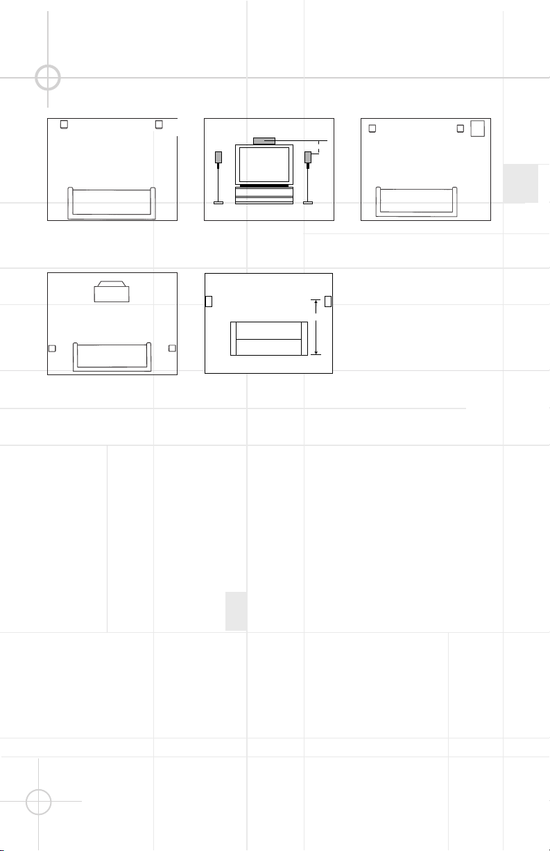
MOUNTING OPTIONS
Satellites and Surrounds
On shelves.
Wall-Mounting
The customer is responsible for
proper selection and use of
mounting hardware, available
through hardware stores, to
properly and safely wall-mount
the speakers.
On the wall. Wall brackets
are included.
On optional stands.

6
Separate and strip the ends of
the speaker wire as shown.
Speakers and electronics
terminals have corresponding
(+) and (–) terminals. Most
manu-facturers of speakers
and electronics, including JBL,
use red to denote the (+)
terminal and black for the (–)
terminal.
The (+) lead of the speaker wire
is noted with a stripe. It is
important to connect all
speakers identically: (+) on the
speaker to (+) on the amplifier
and (–) on the speaker to (–) on
the amplifier. Wiring “out of
phase” results in thin sound,
weak bass and a poor stereo
image.
With the advent of multichannel
surround-sound systems,
connecting all of the speakers
in your system with the correct
polarity remains equally
important in order to preserve
the proper ambience and
directionality of the program
material.
SPEAKER CONNECTIONS
Connection Tips

7
Dolby* Pro Logic* (Non-Digital) – Speaker Level
Use this installation method for
Dolby Pro Logic applications
(not Dolby Digital, DTS®or
other digital processing),
where the receiver/processor
does not have a subwoofer
output, or a volume-controlled
preamp (line-) level output:
Connect your receiver or
amplifier’s front left and right
speaker terminals to the left
and right terminals on the
subwoofer that are marked
“High Level In.” Connect the
left and right terminals on the
subwoofer that are marked
“High Level Out” to the corresponding terminals on the
back of your front left and right
speakers.
Connect your receiver or
amplifier’s center, left and right
surround-speaker terminals to
the corresponding terminals on
the back of your center, left and
right surround speakers.
Left Front
+ –
+ – – +
OUT
IN
Left Front Center
+ – + –
Left Surround
+ –
Center
+ –
Subwoofer
HIGH LEVEL
L R
Receiver
Right Surround
Right Front
+ –
Right Front
+ –
+ –
Left Surround
+ –
Right Surround
+ –

Dolby Pro Logic (Non-Digital) – Line Level
8
Use this installation method for
Dolby Pro Logic appli-cations
(not Dolby Digital, DTS®or
other digital processing), where
the receiver/processor is
equipped with a subwoofer
output, or a volume-controlled
preamp (line-) level output:
Use RCA-type patch cords
to connect the line-level
subwoofer outputs on your
receiver or amplifier to the linelevel inputs on the subwoofer.
IMPORTANT: Do not use the
LFE input on the subwoofer
with Dolby Pro Logic
processors. Note: If your
receiver or amplifier only has
one subwoofer output jack,
then you will need to use a Yconnector (not included). Plug
the male end of the Yconnector into your receiver or
amplifier’s subwoofer output
jack, and connect each of the
two female ends to separate
RCA-type patch cords. Finally,
plug the RCA-type patch cords
into the line-level inputs on the
subwoofer.
Connect each speaker to the
corresponding speaker
terminals on your receiver or
amplifier.
Dolby Digital or DTS®(or Other Digital Surround Mode) Connection
Use this installation method for
Dolby Digital, DTS®or other
digital surround processors:
Use the line-level input jack
marked “LFE” for the LowFrequency Effects channel.
Connect this jack to the LFE
output or subwoofer output
on your receiver or amplifier.
Connect each speaker to the
corresponding speaker
terminals on your receiver or
amplifier.
Make sure that you have
configured your surroundsound processor for
“Subwoofer On.” The front left,
front right, center and rear
speakers should all be set to
“Small.”
Note:
When using the LFE input, the
subwoofer's Crossover control
is NOT active, because this
function is controlled by your
surround processor.
When using the LFE input, set
the subwoofer's Volume control
to "Max" and calibrate the
subwoofer level along with the
other speakers according to
the set-up instructions in the
owner's manual for your
surround receiver/amplifier.
LINE LEVEL IN
LFE INPUT
LFE OUT
L
R
SUBWOOFERRECEIVER
Left Front
Subwoofer
Receiver
Subwoofer
Left
Front
+ –
Left
Rear
+ –
Left Surround
+ –
Center
+ –
LineLevel
In
L
R
Out
R L
Center
+ –
Right
Front
+ –
Right
Rear
+ –
Right Front
+ –+ –
Right Surround
+ –

9
OPERATION
MIN MAX
Subwoofer
Level
MIN MAX
Subwoofer
Level
Press the Master Power
Switch (marked Power ¡) to
the ON position to use the
subwoofer. When your receiver
or amplifier is off, or is not
sending program material to
the subwoofer, the subwoofer
will be in standby mode. When
the subwoofer senses an audio
signal, it will automatically turn
itself on. If the subwoofer does
not sense a signal after
approximately twenty minutes,
it will automatically go into
standby mode. If you will be
away from home for an
extended period of time, or if
the subwoofer will not be used,
switch the Master Power
switch
¡
to the "OFF" position.
Volume
HIGH LEVEL
+ – – +
CAUTION
RISK OF ELECTRIC SHOCK
DO NOT OPEN
OUT
IN
L R
LINE LEVEL IN
LFE
L
R
AC 230V~50Hz
200 Watts
IMPORTANT: CONNECT STRIPED WIRE TO RED ( ) SPEAKER TERMINAL.
+
0° 180°
PHASE
Volume can be adjusted using
the Subwoofer Volume Control
£
, as shown.
The crossover filter between
the subwoofer and satellites
can be adjusted using the
Crossover Control ¢. The
optimum setting for the
SCS178 system is with the
Crossover Control ¢set to
the "Min" position.
™
¢¡ £
Crossover
PHASE
The Phase Control ™determines
whether the subwoofer’s pistonlike action moves in and out in
phase with the main speakers or
opposite the main speakers. This is
adjusted by pressing the button to
the 0°, or 180° position. The 0°
position of the phase button plays
the bass signal in phase with the
main speakers. The 180° position
plays the bass signal 180º, or out of
phase with the main speakers.
Proper phase adjustment depends
on several variables such as
subwoofer placement and listener
position. Adjust the phase switch to
optimize bass output at the
listening position.
Every system, room and listener is
different. There are no right or
wrong settings. This switch offers
the added flexibility to adjust your
subwoofer for optimum
performance for your specific
listening conditions without having
to move your speakers. If at some
time in the future you happen to
rearrange your listening room, and
move your speakers, you should
experiment with the phase switch
in both positions, and leave it in the
position that optimizes bass
performance for your taste.

10
If there is no sound from any of
the speakers:
• Check that receiver/amplifier
is on and a source is playing.
• Check that the powered
subwoofer is plugged in, its
Power switch ¡is switched
on to the “ON•” position.
• Check all wires and
connections between
receiver/ amplifier and
speakers. Make sure all wires
are connected. Make sure
none of the speaker wires are
frayed, cut or punctured.
• Review proper operation of
your receiver/amplifier.
If there is no sound coming
from one speaker:
• Check the “Balance” control
on your receiver/amplifier.
• Check all wires and connections between receiver/
amplifier and speakers. Make
sure all wires are connected.
Make sure none of the
speaker wires are frayed, cut
or punctured.
• In Dolby Digital or DTS
®
modes, make sure that the
receiver/processor is
configured so that the
speaker in question is
enabled.
If there is no sound from the
center speaker:
• Check all wires and
connections between
receiver/
amplifier and speaker. Make
sure all wires are connected.
Make sure none of the
speaker wires are frayed, cut
or punctured.
• If your receiver/processor is
set in Dolby Pro Logic mode,
make sure the center speaker
is not in phantom mode.
• If your receiver/processor
is set in Dolby Digital or DTS
®
mode, make sure the
receiver/processor is configured so that the center
speaker is enabled.
If the system plays at low
volumes but shuts off as
volume is increased:
• Check all wires and connections between receiver/
amplifier and speakers. Make
sure all wires are connected.
Make sure none of the
speaker wires are frayed, cut
or punctured.
• If more than one pair of main
speakers is being used, check
the minimum impedance
requirements of your
receiver/amplifier.
If there is low (or no) bass
output:
• Make sure the connections to
the left and right “Speaker
Inputs” have the correct
polarity (+ and –).
• Make sure the subwoofer is
plugged into an active
electrical outlet.
• Make sure the powered
subwoofer is plugged in and
switched on.
• In Dolby Digital or DTS
®
modes, make sure your
receiver/processor is
configured so that the
subwoofer and LFE output are
enabled.
If there is no sound from the
surround speakers:
• Check all wires and
connections between
receiver/ amplifier and
speakers. Make sure all wires
are connected. Make sure
none of the speaker wires are
frayed, cut or punctured.
• Review proper operation of
your receiver/amplifier and its
surround-sound features.
• Make sure the movie or TV
show you are watching is
recorded in a surround-sound
mode. If it is not, check to see
if your receiver/ amplifier has
other surround modes you
may use.
• In Dolby Digital or DTS
®
modes, make sure your
receiver/processor is
configured so that the
surround speakers are
enabled.
• Review the operation of your
DVD player and the jacket of
your DVD to make sure that
the DVD features the desired
Dolby Digital or DTS®mode,
and that you have properly
selected that mode using both
the DVD player’s menu and
the DVD disc’s menu.
TROUBLESHOOTING

11
Declaration of Conformity
We, Harman Consumer International
2, route de Tours
72500 Château-du-Loir
France
declare in own responsibility, that the product
described in this owner’s manual is in
compliance with technical standards:
EN 60065:1998
EN 55013/A14:1999
EN 55020/A14:1999
EN 61000-3-2/A14:2000
EN 61000-3-3/1.1995
EN 50081-1:1992
EN 50082-1:1992
Luc Emmanuel Godard
JBL,
Harman Consumer International
France, 08/01

JBL Consumer Products
250 Crossways Park Drive, Woodbury, NY 11797
Europe: 2. Route de Tours, 72500 Château du Loir, France
www.jbl.com
©2001 JBL, Incorporated.
JBL is a registered trademark of JBL, Incorporated.
Part No.
1111-SCS178
Refinements may be made on occasion to existing products without notice,
but will always meet or exceed original specifications unless otherwise stated.
Simply Cinema is a registered trademark of JBL, Incorporated.
* Dolby and Pro Logic are trademarks of Dolby Laboratories.
DTS®is a registered trademark of Digital Theater Systems, Inc.
SCS178 Satellite
Frequency Response (-6dB): 90Hz – 22kHz
Sensitivity (2.83V/1m): 86dB
Nominal Impedance: 4 Ohms
Recommended Amplifier Power 25 – 100 Watts RMS per Channel
Drive Units: 12mm Polyamide/Titanium Laminate Video-shielded HF
100mm Paper Cone Video-shielded Mid/Bass
Dimensions (H x W x D): 235mm x 140mm x 179mm (9.3" x 5.5" x 7")
Weight: 2.8kg (6.2lb)
SCS178 Center
Frequency Response (-6dB): 100Hz – 22kHz
Sensitivity (2.83V/1m): 88dB
Nominal Impedance: 4 Ohms
Recommended Amplifier Power 25 – 100 Watts RMS per Channel
Drive Units: 12mm Polyamide/Titanium Laminate Video-shielded HF
Dual 100mm Paper Cone Video-shielded Mid/Bass
Dimensions (H x W x D): 145mm x 402mm x 155mm (5.7" x 15.8" x 6.1")
Weight: 4.5kg (9.9lb)
SCS178 Active Subwoofer
Low Frequency Cut-off: 35Hz
High Frequency Cut-off: 40 Hz - 160Hz Variable
Built-in Power Amplifier: 100 Watts RMS
Drive Unit: 200mm Paper Cone Long Throw Driver. Bass Reflex Enclosure
Dimensions (H x W x D): 450mm x 250mm x 360mm (17.7" x 9.8" x 14.2")
Weight: 13.6kg (30lb)
SCS178 System
Frequency Response (-6dB): 35Hz – 20kHz
OWNER’S GUIDE
PRODUCT LINE:
SCS178 (230V)
DESIGN GOAL: Bring the thrill of live performance and movie sound to the
home environment by calling on JBL’s professional engineering leadership.
SATELLITE TYPE:Titanium-laminate-dome tweeter, reflex-loaded enclosure
SUBWOOFER TYPE: Bass-reflex enclosure
PORT DESIGN: FreeFlow™ flared
PROFESSIONAL REFERENCE: Cinema Loudspeaker Series
®
MODEL
NUMBER:
PRO SOUND
COMES HOME
™
SPECIFICATIONS
 Loading...