


1. Introduction
Thanks for purchasing your new GT series automotive amplifier. The GT series amplifier you have chosen includes many unique features to enhance its performance and utility. The power amplifier circuitry is a fully discrete design notable for its low distortion and unusually clean and clear sound quality. Your GT series amplifier will easily connect to virtually any car audio system, whether it is factory installed or one purchased separately.
In addition to conventional preamplevel inputs, this model features JBL’s Universal Interface design, which facilitates simple connection to factory radios with the low distortion that is usually only associated with preamp level connection. With Universal Interface, a factory radio can be used either as the main music source or combined with a CD player or changer, which includes volume control capability, simultaneously connected to the amplifier. By providing this two-unit direct connection, Universal Interface circuitry eliminates the need for an FM modulator to interface a CD player to factory radios, improving the fidelity of digital playback.
In addition, when using a highpowered (BTL) radio through the speaker-level inputs, Common Sense turn-on circuitry senses the common-mode voltage present on the radio’s speaker wires, turning the amplifier on without an additional “remote” wire.
Also, the built-in active crossover provides either full-range, highpass or low-pass operation. This lets your GT series amplifier power
either subwoofer or component speakers in a bi-amplified system, or conventional full-range speakers in simpler systems.
The GTS300 and 600 also include preamp-level outputs which can provide either full-range, high-pass or low-pass signal to drive additional amplifiers. This lets you build systems of virtually any design without requiring a separate electronic crossover.
1.2 About Installation
Although the GTS300 and GTS600 are designed to make installation as easy as possible, they are sophisticated products that require proper installation to realize their full performance potential.
If you feel you do not have the necessary knowledge and skills we strongly recommend that the installation be done by your authorized JBL dealer.
If you choose to install the GTS300 or GTS600 yourself read all of the information in this manual
before you start the installation. Pay particular attention to the safety precautions and notes.
2. Installation and Use
Refer to the “Crossover Frequency Adjustments” and “Speaker Level Input Impedance Adjustments” sections of this manual to see if you will need to make alterations to their factory settings. If you are not using the built-in crossover, or the speaker level inputs, you may skip this step.
1.Disconnect the negative cable from the battery. Note: If the vehicle’s radio features a code type security system, make certain you know the code
1
before disconnecting the battery!
2.Run a minimum AWG #8 power cable complete with a 40 amp fuse (not included) for the GTS300 or an AWG #6 or AWG #4 cable with an 80 amp fuse for the GTS600 directly from the positive + 12V battery terminal to the disired amplifier location. Keep the fuse to within 6” of the battery terminal, and before the wire runs through any metal
partition.
Note: All wiring connections should be made either by soldering with heatshrink tubing insulation or with high quality crimp type insulated connectors installed with a professional type, articulated crimping tool. Soldering crimptype terminals is recommended for additional security. Never use wire-nuts, insulation-displacement connectors (i.e. ScotchLok type), or “twist and tape” connections. Do not use electrical tape; it will loosen with age and extreme temperatures.
3.Mount amplifier in the desired location using four screws.
4.Connect power wiring as shown i the Wiring Diagram.
5.Connect the outputs from the head unit to the appropriate inputs of the amplifier according to the Wiring Diagram with either high quality low-level signal cables with RCA plugs, with the supplied speaker-level input connector, or both.
6.Connect the speakers to the amplifier according to the wiring diagram.
7.Turn the input gain adjustment to the 1/4 position.
8.Set the crossover switches as desired.
9.Set the input mode switch to stereo, left + right or right input only operation.
10.Set the bass boost switch to the desired position.
11.Reconnect the negative battery cable.
12.Turn on the signal source at a low volume level and check for the correct output from each speaker.
13.Adjust the amplifier gain control using the procedure described in the “Adjusting the Gain” section.
2.2 Controls and Connectors
1.Preamp-Level Input Connector –
Use these connectores for line (preamp) level input to the amplifier.
2.Preamp-Level Output Connector
– Use these outputs to send the signal to additional amplifiers.
3.Speaker-Level Input Connector –
Use this connector for speaker level input signals. A wire harness is supplied for use with this connector. This input also includes JBL’s Common Sense input circuitry which turns the amplifier on as soon as the high powered head unit connected to this input is turned on.
4.Speaker Output Connector –
Connect speaker wiring to this connector. See “Wiring” directions for more information.
5., 6., 7., 8., Power Connector –
Connection for power wires #A. See “Wiring” directions for information on proper connections.
2
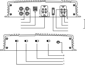
9.Fuse – 40 Amp ATC type fuse for the GTS300 and two 40 amp fuses for the GTS600.
10.Gain Control – Use this control to adjust the input sensitivity of the amplifier. See the “Adjusting the Gain” section for tips on proper setup.
11.Preamp-Output Crossover Switch – This switch controls the built-in crossover that is directed to the preamp-output connectors. Set the switch to “Flat” for full band operation. Set this switch to “Low-Pass” to activate the lowpass filter on the preamp output (for subwoofer use). Set the switch to “High-Pass” to activate the high-pass filter for use with satellite speakers.
12.Speaker Output Crossover Switch – This switch controls the built-in crossover that is connected to the power amplifier circuitry. Set the switch to “Flat” for full band operation. Set this switch to “Low Pass” to activate the low
pass filter on the amplifier (for subwoofer use). Set the switch to “High Pass” to activate the high pass filter for use with satellite speakers.
13.Input Mode Selector – This switch is used to set the input mode for both preamp and speaker-level inputs.
Set this switch to Stereo for normal operation using both left and right inputs. Set this switch to R to drive both the left and right output channels with only a single input on the right channel. Set this switch to “L+R” to sum the left and right inputs for a mono output on both amplifier channels.
Power Indicator LED (on chassis top) – LED steadily illuminates for normal operation. LED blinks when protection circuitry or muting is engaged.
14.Bass Boost Switch – This activates a built-in Bass Boost circuit used to increase low-bass output.
LINE |
PREAMP |
SPEAKER LEVEL |
|
SPEAKER |
|
|
OUTPUT |
||||
INPUT |
OUTPUT |
|
INPUT |
|
|
|
|
+ |
+ |
|
|
L |
L |
R |
L |
+ |
+ |
|
|
_ |
_ |
||
|
|
|
|
R |
L |
|
|
|
|
_ |
_ |
R |
R |
|
|
|
|
|
|
|
BRIDGED |
|
|
Preamp Level RCA Inputs
Preamp Level RCA Outputs
High Level Speaker Inputs
Speaker Outputs
FUSE 40A
40A
POWER
REM IN
REM OUT
BATT(+) |
GND |
Remote Turn On Output
Battery Ground
Power
Battery (+12v) In Connector
Remote Turn On Input
Fuse
|
BASS BOOST |
INPUT MODE |
|
SPEAKER OUTPUT |
|
PREAMP OUTPUT |
|
|
|
|
|
CROSSOVER |
|
CROSSOVER |
|
NOM |
|||
OFF |
ON |
R |
L+R |
FLAT |
HIGH PASS |
FLAT |
HIGH PASS |
||
|
|||||||||
|
|
STEREO |
|
LOW PASS |
|
LOW PASS |
MIN |
MAX |
|
|
|
|
|
|
|
|
|||
|
|
|
|
|
|
|
|
GAIN |
|
|
|
|
|
|
|
|
|
Gain Control |
|
|
|
|
|
|
|
|
|
Preamp Crossover Frequency Selector |
|
|
|
|
|
|
|
|
|
Amplifier Crossover Frequency Selector |
|
|
|
|
|
|
|
|
|
Input Mode Selector |
|
|
|
|
|
|
|
|
|
Bass Boost |
|
|
|
|
|
|
|
3 |
|
|
3. System Design Using the GTS300 or GTS600:
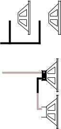
3.1 Speaker Requirements
When used in the non-bridged mode the GTS300 or GTS600 can easily drive 2 ohm speaker loads. When only one speaker is connected to each channel, virtually any conventional speaker may be used.
When the GTS300 or GTS600 is in bridged mode, the combined impedance of the speaker (or speakers) connected to the bridged channel should be at least 4 ohms. Sustained operation of the GTS300 or GTS600 in bridged mode with less than 4 ohms will likely cause overheating.
The GTS300 or GTS600 must not be used with speakers that have either one of their input terminals wired to the frame of the speaker or to the chassis of the vehicle.
Parallel Wiring
(+) |
|
|
|
|
|
|
|
|
|
|
|
|
|
|
|
2 Ohms |
|
|
4 Ohms |
|
|
4 Ohms |
|
Nominal |
|
|
|
|
|||
Impedance |
|
|
|
|
|
|
|
(–)
Series Wiring
(+)
4 Ohms
8 Ohms
Nominal
Impedance
(–) 

 4 Ohms
3.2 Signal Sources
The low level preamp outputs of any radio/tape deck, CD player or preamp/equalizer so equipped can drive the GTS300 or GTS600. The gain controls of the GTS300 or GTS600 are used to match the amplifier’s input sensitivity to the output voltage of the source. This matching is important to keep noise low and is explained in the “Adjusting the Gain” section of this manual.
Thanks to Universal Interface Circuitry, the GTS300 or GTS600 can also be connected to power amplifiers, radios or equalizers that are equipped with only speaker outputs by connecting them through the speaker level input connector. Inside the GTS300 or GTS600, the speaker-level and preamp-level inputs are connected through a mixing circuit, which allows them to be used simultaneously. Therefore a low level source, such as a CD player equippe with a volume control may be connected to the preamplevel inputs at the same time as a powered radio/tape unit is connected to the speaker-level inputs. This provides a higher performance alternative to an FM Modulator connection when you wish to add CD capability to a factory casette stereo. Switching from one source to the other is as simple as turning the desired source on and turning the undesired one off – no additional switches or relay connections are needed.
4. Wiring
Proper wiring of the GTS300 or GTS600 and the associated
4

components is extremely important for proper performance and long term reliability.
All wiring connections should be made either by soldering with heatshrink tubing insulation or with high quality crimp type insulated connectors installed with a good crimping tool. Soldering crimp connections is recommended to further enhance connection reliability. Never use wire-nuts, insulation-displacement connectors (i.e. ScotchLok type), or “twist and tape” connections. Do not use electrical tape; it will
loosen with age and extreme temperatures. Never leave bare wire exposed.
Route the wiring through the car carefully. Do not allow wires to lay against sharp sheet metal edges or any other surfaces that might wear away or cut through the insulation of the wire. Use insulated strain reliefs, rubber grommets and plastic tubing to protect the wires whenever they are run through sheet metal panels or are placed where they might be pulled or damaged.
Cassette/CD Tuner
Speaker Level Output Connection (Use only when line level ouput is not available)
|
|
|
|
|
Cassette/CD Tuner |
|
CD Player |
|
|
|||
|
|
|
|
|
|
|
|
|
|
or Changer |
|
|
|
|
|
Antenna Input |
|
|
CD Input |
|
|
|
|||
|
|
|
|
|
|
|
|
|
|
|
|
|
|
Power |
|
|
Cassette/Receiver |
|
|
|
|
|
|||
|
Antenna |
|
|
|
|
|
|
|||||
|
|
Power Supply |
|
|
|
|
|
|||||
|
|
|
|
|
Wires |
|
|
|
|
|
|
|
|
|
Power |
|
|
|
|
|
Cassette/CD Preamp Output |
Amplifier |
|
|
|
|
|
|
|
|
|
|
|
|
|
|
||
|
|
Antenna |
|
|
|
|
|
|
Power |
|
|
|
|
|
Relay |
|
|
|
Fuse |
Fuse |
|
|
Connection |
|
|
|
|
|
|
Black - Power Ground |
R |
|
|
|
|
|||
|
|
|
|
|
|
|
|
|
||||
|
|
|
|
|
|
|
N TH E |
|
|
|
|
|
Antenna Motor |
Power Supply |
Blue(Blue/White) |
RemoteAntenna |
RemoteOn/Off |
Red - Main +12V |
Yellow - Back Up Power |
WOEP |
USA |
|
|
|
|
|
Amplifier |
|
|
|||||||||
|
Speaker |
|
|
|||||||||
|
Level |
|
|
|||||||||
Line |
Input |
Amplifier |
|
|||||||||
|
Speaker |
|
||||||||||
Input |
|
Output |
|
|||||||||
|
|
Connection |
+ |
|||||||||
|
|
|
|
|
|
|
|
|
|
|
||
|
|
|
|
|
|
|
|
|
|
|
Speakers |
|
|
|
|
|
|
|
|
|
Blue w/White Stripe - Remote On/Off |
|
|
||
|
|
|
|
|
|
|
|
|
|
|
||
|
|
|
Ignition Switch |
|
GTS300 – 40 Amp |
|
|
|
– |
|||
|
|
|
|
|
|
|
|
|
|
|
|
|
|
|
|
|
|
|
|
|
GTS600 – 80 Amp |
|
|
|
|
|
|
|
|
|
|
|
|
(Not Included) |
|
|
|
+ |
|
|
|
|
|
|
|
|
Fuse |
Main +12V |
|
|
|
|
|
|
|
|
|
|
|
|
|
|
|
|
|
|
|
– |
|
|
|
+ |
|
|
|
|
|
Vehicle Battery
Power Ground
Chassis Ground
5
 Loading...