


 GTH400-20107 06/03/98 15:49 Side 26

 GTH400-20107 06/03/98 15:49 Side 1
GTH400
6/5/4/3 CHANNEL AUTOMOTIVE POWER AMPLIFIER OWNER’S MANUAL


 G T H 4 0 0


 GTH400-20107 06/03/98 15:49 Side 2
Table of Contents
1. |
Introduction...................................................................................... |
3 |
|
|
1.1 |
Features .................................................................................... |
4 |
|
1.2 |
About Installation ...................................................................... |
4 |
2. |
Installation and use .......................................................................... |
5 |
|
3. |
System Design with the GTH400..................................................... |
6 |
|
|
3.1 |
Speaker Requirements ............................................................. |
6 |
|
3.2 |
Typical Applications.................................................................. |
7 |
4. |
Installation and Use ......................................................................... |
9 |
|
|
4.1 |
Controls and Connectors.......................................................... |
9 |
|
4.2 |
Internal Adjustments ................................................................ |
12 |
|
|
Speaker-Level Input Impedance Adjustments......................... |
12 |
|
|
Crossover Frequency Adjustments.......................................... |
12 |
|
|
Custom Chip construction....................................................... |
13 |
|
|
Remote Chassis Installation .................................................... |
13 |
|
|
Unter-Dash Remote Installation............................................... |
14 |
|
|
In-Dash remote Installation...................................................... |
14 |
|
|
Power Supply Connections ..................................................... |
14 |
|
|
Simultaneous Speaker Stereo-Mono Connection Diagram..... |
16 |
|
|
Speaker-Level Input Harness - Color Codes........................... |
17 |
5. |
Adjusting the Gain .......................................................................... |
17 |
|
6. |
Important Characteristics ............................................................... |
19 |
|
7. |
In Case of Difficulty......................................................................... |
21 |
|
8. |
Specifications ................................................................................. |
23 |
|
Owner’s Warranty Information
Model Number
Serial Number
Dealer Name
City, State, Zip
Sales Receipt Number
Date of Purchase

 GTH400-20107 06/03/98 15:49 Side 3
1. Introduction
Thanks for purchasing your new GT series automotive multichannel amplifier. Your GT series amplifier will easily connect to virtually any car audio system, whether it is factory installed or one purchased separately. The GTH400 includes an abundance of unique features which are described in this manual. The most obvious feature of the GTH400 is its 6-channel, staggered-power design. This design provides the simplicity of driving an entire system with a single amplifier without compromise. The flexible design of the GTH400’s built-in crossover circuitry also allows elaborate systems to be built more simply than with conventional components. For optimum performance, the power amplifier circuitry is a fully discrete design notable for its low distortion and unusually clean and clear sound quality.
In addition to conventional preamplevel inputs, the GTH400 features JBL’s Universal Interface design, which facilitates simple connection to factory radios with the low distortion that is usually only associated with preamp level connection. In addition, when using a high-powered (BTL) radio through the speaker-level inputs, Common Sense turn-on circuitry senses the common-mode voltage present on the radio’s speaker wires, turning the amplifier on without an additional remote wire.
3

 GTH400-20107 06/03/98 15:49 Side 4
1.1 Features
Theory of Operation –
Virtual Center Image Enhancer
JBL’s breakthrough “Virtual Center” circuitry is the result of the understanding of how the human ear responds to timing, frequency, and amplitude cues to determine the apparent direction of a sound source. Virtual Center circuitry manipulates the analog signal in real time to provide each of the driver’s ears with the signal they would receive if the driver was seated in the center of the vehicle. This provides a stable, centered image to the driver much like that obtained with a dedicated center-channel loudspeaker.
To restore the spaciousness that is generally lost in the small confines of a car interior, the rear channels utilize differential-mode ambience recovery to restore the ambience information present in all conventional stereo recordings. Unlike DSP, the JBL circuitry does not add synthetic reverb, but recovers real information that is masked in conventional systems. As a result, the overall effect from the Virtual Center circuitry of the GTH400 is incredibly realistic, yet simple to adjust and use. Best of all, the “Virtual Center” and ambiance recovery circuits do not require specially encoded recordings and work with virtually all conventional stereo tapes, discs, and broadcasts.
1.2 About Installation
Although the GTH400 is designed to make installation as easy as possible, it is an extremely sophisticated product that requires proper installation and setup to realize its full performance potential. If you feel you do not have the necessary knowledge and skills, we strongly recommend that the installation be done by your authorized JBL dealer.
If you choose to install the GTH400 yourself, read all of the information in this manual before you start the installation. Pay particular attention to the safety precautions and notes.
4

 GTH400-20107 06/03/98 15:49 Side 5
2. Installation and use
Refer to the “Crossover Frequency Adjustments” and “Speaker-Level Input Impedance Adjustments” sections of this manual to see if you will need to make alterations to their factory settings.
1.Disconnect the negative cable from the battery. Note: If the vehicle’s radio features a code type security system, make certain you know the code before disconnecting the battery!
2.Run a minimum AWG #8 power cable complete with a 60 amp fuse (not included) directly from the positive +12V battery terminal to the desired amplifier location. Keep the fuse within 6" of the battery terminal, and position it before the wire runs through any metal partition.
3.Note: All wiring connections should be made either by soldering with heatshrink tubing insulation or with high quality crimp-type insulated connectors installed with a professional-type, articulated crimping tool. Soldering crimp-type terminals is recommended for additional
security. Never use wire nuts, insulation-displacement connectors (i.e. ScotchLok type), or twist and tape connections. Do not use electrical tape; it will loosen with age and extreme temperatures.
4.Mount amplifier in the desired location using the included screws.
5.Connect power wiring as shown in the Wiring Diagram on page 18.
6.Connect the outputs from the head unit to the appropriate inputs of the amplifier according to the Wiring Diagram (page 18) with either (or both) high quality low-level signal cables with RCA plugs, or the supplied speaker-level input connector.
7.Install the remote control in the desired location. Connect and run the cable from the remote to the amplifier.
8.Connect the speakers to the amplifier according to the Wiring Diagram on page 18.
9.Turn the gain controls to the 1/4-position for all groups.
10.Set the bass boost of each group to the desired position.
11.Set the crossover switches for each group as desired.
12.Set the Group 2 Input and Group 3 Input as desired.
13.Set the mode switches to Stereo, Left + Right, or Left Input Only operation for each group.
14.Double-check your switch settings. Reconnect the negative battery cable. Note: Incorrect switch settings can damage your speakers!
15.Turn on the signal source at a low volume level, and check for the correct output from each speaker.
16.Adjust the amplifier gain controls using the procedure described in the “Adjusting the Gain” section (page 25).
17.Read the rest of the manual to get maximum use and enjoyment from your amplifier.
5
 GTH400-20107 06/03/98 15:49 Side 6
3. System Design Using
the GTH400
3.1 Speaker Requirements
When used in the non-bridged mode a group-channel of the GTH400 can easily drive two 2-ohm speaker loads. When only one speaker is connected to the left and right outputs of a group, virtually any conventional speaker may be used. When two speakers are connected in parallel to a single output (left or right) of a given group, each speaker must have a minimum impedance of at least 4 ohms. This ensures that the combined load will not drop below 2 ohms. Although the amplifier will not be damaged, load impedances lower than 2 ohms will eventually cause the amplifier to overheat, activating the protection circuits and causing the unit to shut off until it cools down sufficiently.
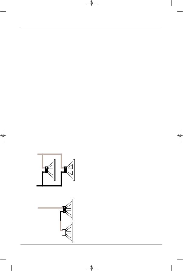
Parallel Wiring
(+) |
|
|
2 ohms |
|
|
Nominal |
4 ohms |
4 ohms |
Impedance |
|
|
(–)
Series Wiring
(+)
4 ohms
8 ohms Nominal Impedance
(–) 

 4 ohms
When a group of the GTH400 is in bridged mode, the combined impedance of the speaker (or speakers) connected to the bridged channels should be at least 4 ohms. As in the example above, sustained operation of the GTH400 in bridged mode with less than 4 ohms will likely cause overheating.
The GTH400 must not be used with speakers that have either one of their input terminals wired to the frame of the speaker or to the chassis of the vehicle.
6

 GTH400-20107 06/03/98 15:49 Side 7
3.2 Typical Applications
The diagrams on pages 8 & 9 show the most common basic system configurations of the GTH400. One or more of these building blocks may
be combined to form elaborate system designs.
Application 1
6-Channel Bi-Amplified System with Non-Fading Subwoofers
|
Group 1 |
Group 2 |
Group 3 |
Mode |
Stereo |
Stereo |
Stereo |
Group 2 Input |
– |
GR 2 |
– |
Group 3 Input |
– |
– |
GR 1+2 |
Speaker Crossover |
High Pass |
High Pass |
Low Pass |
Preamp Crossover |
– |
– |
– |
The GTH400 uses the terminology “Group 1,” “Group 2” and “Group 3” to indicate the three main signal paths within the amplifier. Each “group” may consist of a mono bridged signal or a stereo pair of L+R signals depending on the system configuration.
|
|
|
|
|
|
|
|
|
|
|
|
|
|
|
|
|
|
|
|
|
|
|
|
|
|
|
|
|
|
|
|
|
|
|
|
|
|
|
|
|
L |
R |
L |
|
R |
||||||
Front |
|
Preamp or |
|
Rear |
||||||||
Speaker-Level |
|
|||||||||||
|
|
L |
R Input |
L |
|
R |
||||||
|
GR 1 |
|
|
|
|
|
|
GR 2 |
||||
|
|
|
|
|
|
|
|
|
|
|
|
|
|
|
|
|
|
|
|
|
|
|
|
|
|
|
|
|
|
|
|
|
|
|
|
|
|
|
|
|
|
|
|
|
|
|
|
|
|
|
|
|
|
|
|
|
|
|
|
|
|
|
|
|
|
|
|
|
|
|
|
|
|
|
|
|
|
|
|
|
|
|
|
|
|
|
|
|
|
|
|
|
|
|
|
|
|
|
|
|
|
|
|
|
|
|
|
|
|
|
|
|
|
|
|
|
|
|
|
|
|
|
|
|
|
|
|
|
|
|
|
|
|
|
|
|
|
|
|
|
|
|
|
|
|
|
|
|
|
|
|
|
|
|
|
|
|
|
|
|
|
|
|
|
|
|
|
|
GTH400
GR 1 |
L– |
GR 2 |
L– |
GR 3 |
L– L+ |
L+ |
L+ |
||
R– |
R+ |
R– |
R+ |
R– R+ |
– |
+ – |
+ |
– |
+ – |
+ |
– |
+ – |
+ |
L |
R |
|
L |
R |
|
L |
|
R |
Front Speakers Rear Speakers Subwoofers
Application 2 |
|
|
|
|
|
|
|
|
5-Channel Bi-Amplified System with |
|
|
|
|
|
|
||
Non-Fading Mono Subwoofer |
|
L |
R |
|
L |
R |
||
|
|
|
Front |
Preamp or |
Rear |
|||
|
|
|
Speaker-Level |
|||||
Mode |
Group 1 |
Group 2 |
Group 3 |
L |
R |
Input |
L |
R |
Stereo |
Stereo |
L+R |
GR 1 |
|
|
|
GR 2 |
|
Group 2 Input |
– |
GR 2 |
– |
|
|
|
|
|
Group 3 Input |
– |
– |
GR 1+2 |
|
|
|
|
|
Speaker Crossover |
High Pass |
High Pass |
Low Pass |
|
|
|
|
|
Preamp Crossover |
– |
– |
– |
|
|
|
|
|
|
|
|
GTH400 |
|
|
|
|
|
|
|
|
GR 1 |
L+ |
L– |
GR 2 |
|
GR 3 |
|
|
|
L– |
L+ |
|
L– R+ |
||
|
|
|
|
R– |
R+ |
R– |
R+ |
|
– |
+ |
– |
+ |
|
L |
|
R |
– |
+ |
– |
+ |
– |
+ |
|
L |
|
R |
|
|
Front Speakers |
Rear Speakers |
Subwoofer |
 Satellite Speakers
7
 Loading...