


Intonato 24
Table of contents
 Loading...
INTONATO | 24
Monitor Management Tuning System
Operation Manual

Table of Contents
Introduction ����������������������������������������������������������������������1
Features ����������������������������������������������������������������������������3
Front Panel Overview ������������������������������������������������������4
Rear Panel Overview �������������������������������������������������������6
Installing the Intonato 24 �������������������������������������������������9
Rack Installation �������������������������������������������������������������������������9
Making Audio Connections ��������������������������������������������������������9
Applying Power ��������������������������������������������������������������������������9
Installing the JBL Intonato Control App �����������������������10
Device Requirements ���������������������������������������������������������������10
Downloading and Installing the App ������������������������������������������10
Connecting to the Network �������������������������������������������11
Connecting to a Wired Network Switch or Router ���������������������11
Connecting to a Wi-Fi Network Router ��������������������������������������12
Using the Intonato 24 Control App �������������������������������13
Discovering Devices on the Network �����������������������������������������13
Selecting the Speaker Layout Type �������������������������������������������14
About Speaker Layouts, Profiles, and Scenes �����������������������15
About the Aux Outputs ���������������������������������������������������������16
Configuring Inputs ��������������������������������������������������������������������17
Configuring Outputs �����������������������������������������������������������������19
Configuring Utility Settings ��������������������������������������������������������21
Configuring BLU link Outputs ���������������������������������������������������23
Calibrating the System �������������������������������������������������������������24
User EQ Refinement Recommendations �������������������������������25
Balancing Subwoofers – Bass Management and LFE Levels �26
The System Calibration Screen ���������������������������������������������28
Adjusting User EQ ��������������������������������������������������������������������32
Using Profiles ���������������������������������������������������������������������������34
Creating Scenes ����������������������������������������������������������������������36
Setting the Security Password and Updating Firmware �������������38
The Desktop Controller Screens �����������������������������������������������39
User Control – Master Controls �������������������������������������������������40
User Control – Recalling Scenes �����������������������������������������������43
Configuring the Clock Source ��������������������������������������76
Clocking via the Internal Clock ��������������������������������������������������77
Clocking via AES ����������������������������������������������������������������������78
Clocking via Word Clock ����������������������������������������������������������79
Using BLU link ����������������������������������������������������������������80
BLU link Specifications �������������������������������������������������������������80
Making BLU link Connections ���������������������������������������������������80
BLU link Mastership �����������������������������������������������������������������81
BLU link Fault Tolerance �����������������������������������������������������������81
BLU link Port LED Indicators �����������������������������������������������������82
Configuring Crown DCi Network Series Amplifiers ���������������������83
Speaker Tunings ������������������������������������������������������������87
The Intonato DC Desktop Controller ����������������������������88
Networking ���������������������������������������������������������������������89
Networking Overview ���������������������������������������������������������������89
Network Security ���������������������������������������������������������������������90
Network Troubleshooting ���������������������������������������������������������90
®
Using HiQnet
Configuring the Network Using NetSetter ������������������������������92
NetSetter™ �������������������������������������������������������92
Signal Path Block Diagram �������������������������������������������93
Dimensions ��������������������������������������������������������������������������94
Specifications ����������������������������������������������������������������95
Appendix ������������������������������������������������������������������������97
Replacing the Fuse ������������������������������������������������������������������97
D-Sub Connector Pinouts ��������������������������������������������������������98
Attribution Notices �������������������������������������������������������������������99
Warranty and Service ��������������������������������������������������100
Contact Information ����������������������������������������������������101
Application Examples ����������������������������������������������������44
2�1 Bi-Amplified Application �����������������������������������������������������44
5�1 Full-Range Application �������������������������������������������������������52
7�2 Bi-Amplified Application �����������������������������������������������������60
Dolby Atmos Application ����������������������������������������������������������68
INTONATO | 24 Operation Manual

Introduction
Introduction
Thank you for purchasing the JBL® Intonato 24 Monitor Management Tuning System. The Intonato
24 is a powerful, sophisticated speaker management processor and monitor controller for audio
recording, post production, and broadcast facilities. With support for mono to immersive surround
formats, the Intonato 24 provides the centerpiece for a scalable audio production monitoring system.
Supported Formats
The Intonato 24 can be configured for mono, stereo, 5.1, 7.1, and greater surround systems,
including burgeoning immersive audio production formats such as Dolby
DTS:X™, and others that use overhead or height surround speakers. Up to 4 subwoofers are
supported, with LFE capabilities, assignable bass management for each satellite speaker, and global
bass management on/off control. Fully customizable downmixing with adjustable downmixing levels is
also supported, allowing various downmix formats to be recalled using scenes.
Inputs
The Intonato 24 can accept up to 24 simultaneous source inputs from various combinations of the 24
line-level analog, 24 digital AES, and 24 BLU link input channels. AES Input C has selectable sample
rate conversion (SRC), which can be enabled when connecting digital devices synchronized from
different clocks (such as their own).
®
Atmos®, Barco® Auro,
Outputs
Up to 24 line-level analog outputs are available for connecting to the amplifiers. Or, up to 24 BLU link
output channels can be routed to BLU link-equipped amplifiers, such as the Crown Audio
models. Two independently adjustable delays are also provided to synchronize the monitor system
and talent headphone mix to video displays and restore “lip synchronization”.
®
DCi N
Mic Input and Stereo Aux Output
The Intonato 24’s XLR mic input can be used for both calibrating the system and for talkback
communication during recording sessions. The stereo aux output (channels 23 and 24 when
configured) carries the talkback signal and supports channel downmixing, making it perfect for
recording voiceover or automatic dialog replacement (ADR) for surround-formatted projects.
Conguration and Control
The Intonato 24 can be configured and controlled from a compatible Windows®, Mac®, iOS®, or
Android
connecting to a DHCP-enabled network via a wired computer connection or a Wi-Fi router and WiFi-equipped device. User control is also available using the dedicated Intonato DC desktop controller
(sold separately).
The Intonato 24 offers six different speaker layout configuration types and works on the principle of
creating a profile for a given type of session, then creating and storing scenes to the profile for later
recall by the studio engineer.
™
device using the free JBL Intonato control app. Network control can be established by
A profile contains all the configuration settings for a given type of session. Up to 30 profiles can be
stored. Scenes contain the various states the studio engineer will need to recall during a session
(source/speaker monitor selection, fold-down mixes, etc.). Up to 30 scenes can be stored to each
profile.
Within scenes, audio inputs can be routed or mixed to outputs with their levels adjusted as necessary.
This provides a great deal of audio routing flexibility to suit the application.
INTONATO | 24 Operation Manual
Page 1

Introduction
For the studio engineer, the Intonato 24 provides master mute, dim, and monitor volume control, as
well as individual speaker mute/solo control, and monitor SPL indication.
Integrated Auto-Calibration System
The Intonato 24 includes a sophisticated auto-calibration system that leverages JBL’s decades of
experience integrating speaker systems into real-world production environments. Based on JBL’s
proprietary software used to measure acoustics during product development, the Intonato 24
incorporates a powerful hardware-based DSP solution designed to produce a “tuned” monitoring
environment that delivers greater accuracy in a broad range of environments.
Using the supplied calibration microphone, the Intonato 24 analyzes the system performance in the
monitoring environment and automatically matches the level, “time-of-arrival” delay, and frequency
response of all speakers. Furthermore, an infinite number of mic position measurements can be taken
to provide an averaged room frequency response, for very complex yet fast and accurate room EQ
calibration.
Differing distances in speaker placement can prevent correlated signals from summing properly at the
mix position. The Intonato 24’s auto-calibration system ensures the output and “time of arrival” of all
speakers is carefully matched. The auto-calibration system measures the level and time of arrival of
each speaker, and applies the precise amount of attenuation and delay to all speakers to match that
of the most distant speaker.
In the low frequencies, the room is in control. Place a speaker in different places in the room and you
will hear differences in low-frequency response. Although a speaker may deliver neutral frequency
response on-axis in an anechoic environment, when measured at the mix position the response is
altered by the interaction of the loudspeaker and the production environment.
“Room modes” or “standing waves” (low-frequency resonance caused by the geometry and
construction of the room) can augment and attenuate low-frequency response, creating a false
impression of bass at the listening position. This issue can result in mixes that are bass-light or bassheavy when auditioned on systems outside the control room.
During the auto-calibration process, the Intonato 24 measures the low-frequency response delivered
by each speaker and applies settings to tackle effects of low-frequency resonance. Additionally the
system identifies and neutralizes response anomalies caused by the speaker’s proximity to the room’s
walls or work surface. The system is designed to identify low-frequency resonance and boundary
issues below 500Hz and adjust the “Room EQ” to provide flat low-frequency response from all
speakers. In our experience, the desired low-frequency curve varies according to room size and
material.
Once system calibration is complete, the Intonato 24’s “User EQ” allows the system’s frequency
response to be tailored according to preference—for example, to compensate for perforated-screen
transmission loss, or to create the X Curve or another custom frequency-response contour.
Page 2
INTONATO | 24 Operation Manual

Features
Features
• Support for 44.1, 48, 88.2, and 96 kHz sample rates
• Up to 24 simultaneous inputs from the available 24 analog, 24 AES, and 24 BLU link input
channels
• Up to 24 analog and BLU link output channels
• Sample rate conversion for asynchronous connection of up to 8 AES input signals
• Support for mono, stereo, 5.1, 7.1, and greater surround formats, including burgeoning immersive
audio production formats such as Dolby Atmos, Barco Auro, DTS:X, and more
• Mixing matrix with channel-independent level control for flexible routing, mixing, and downmixing
of any combination of AES, Analog, and BLU link inputs to outputs
• Bi-amped speaker support
• LFE support with adjustable LFE low-pass filter frequency
• Bass Management for up to 4 subwoofers, with global bass management on/off control
• Adjustable bass management crossover frequency
• Included measurement microphone and auto-calibration feature for automated system calibration
of output trims, delays, and 12-band room EQ, with support for an infinite number of mic positions
to provide an averaged room EQ response
• Built-in signal generator with pink noise, white noise, and sine wave tone options
• Manually adjustable 8-band parametric EQ and polarity on every output channel
• Independently adjustable delays for synchronizing speaker and headphone monitoring systems to
video displays
• Stereo aux output with downmixing support, talkback, 3-band EQ, and level control—perfect
for providing a headphone mix to talent for voiceover/ADR recording sessions or feeding remote
stereo speakers
• Store up to 30 profiles
• Store up to 30 scenes in each profile for recall of source/monitor selection and fold-down
monitoring
• End-user control of solo and mute for each speaker output
• End-user control of master level, mute, and dim, with dim level adjustment
• Monitor level calibration with SPL readout for reliable level referencing
• Password protection to prevent unauthorized tampering
• Built-in speaker tunings for the JBL M2 speakers, 7 Series speakers, and various JBL subwoofers
• Unit configuration and control using the free JBL Intonato control app, available for compatible
Windows, Mac, Android, and iOS devices
• Optional dedicated Intonato DC desktop controller available
INTONATO | 24 Operation Manual
Page 3
Front Panel Overview
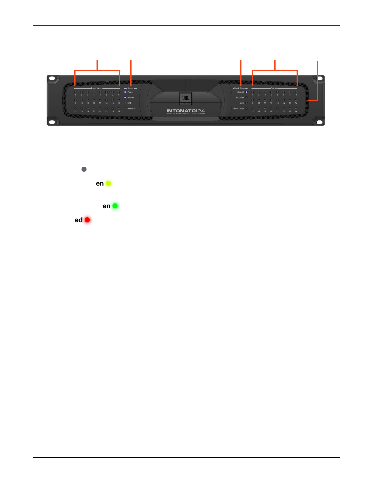
1 2 4
3
Front Panel Overview
1. Input Source LEDs
These LEDs indicate input signal status of the 24 configured inputs post the A/D converters (if
analog) and before the DSP. Signal status is indicated as follows:
•
LED Off – The input channel is not configured for use in the current scene.
• LED Dim Green – The input channel is configured for use in the current scene, but no signal
is detected.
5
•
LED Bright Green – The input channel detects signal level.
• LED Red – The input channel is clipping.
2. Status LEDs
These LEDs indicate status as follows:
Power – Lights to indicate the unit is powered on.
•
• Master – Lights when the Intonato 24 is providing the master clock for the BLU link bus.
• SRC – Lights to indicate sample rate conversion is enabled on AES Input C.
• Network – Lights to indicate a connection has been established with the network.
3. Clock Source LEDs
These LEDs indicate the source providing master clock to the Intonato 24:
Internal – Lights to indicate the Intonato 24 is clocked from the internal oscillator.
•
• BLU link – Lights to indicate the Intonato 24 is clocked from another device on the BLU link
bus.
•
AES – Lights to indicate the Intonato 24 is clocked from the AES signal connected to AES
Input A1.
•
Word Clock – Lights to indicate the Intonato 24 is clocked from the Word Clock (BNC) input.
Page 4
INTONATO | 24 Operation Manual

Front Panel Overview
4. Output LEDs
These 24 output LEDs indicate output signal status post the DSP. Signal status is indicated as
follows:
•
LED Off – The output channel is not configured for use in the current scene.
• LED Dim Green – The output channel is configured for use in the current scene, but no
signal is detected.
•
LED Bright Green – The output channel detects signal level.
• LED Red – The output channel is clipping.
5. Cooling Vents
These vents provide air circulation through the processor. A low-noise fan is used to circulate
air through the Intonato 24 and keep it running at an optimal temperature. The fan is baffled to
appropriately direct airflow and minimize fan noise. When installing the Intonato 24, ensure that all
airflow vents remain unblocked.
INTONATO | 24 Operation Manual
Page 5
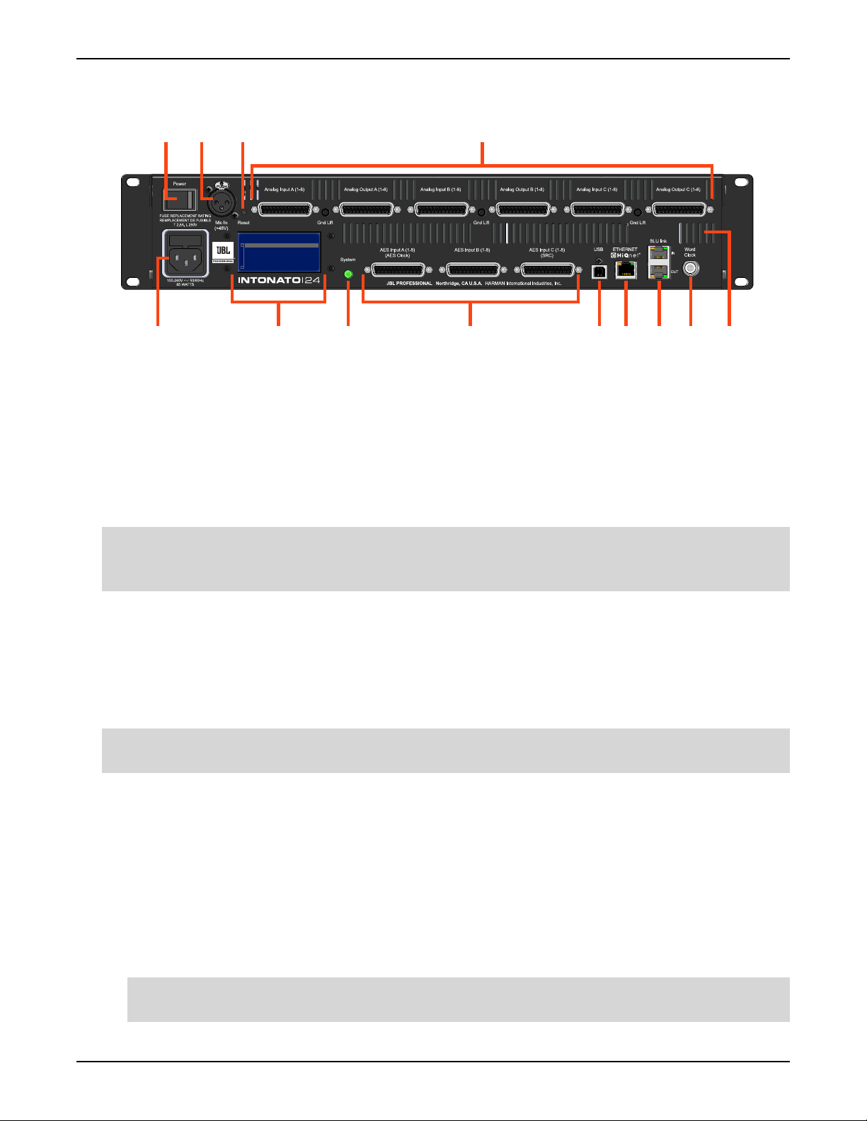
Rear Panel Overview
Rear Panel Overview
1 2 3 4
IP: 169.254.30.21
Events:
HQ: 2:6:801B SYSTEM BOOT
6 8
1. Power Switch
97 10 115
12 13
This rocker-type power switch is used to turn the Intonato 24’s power on or off.
2. Microphone Input Connector
This balanced female XLR input serves two purposes: connect the included measurement
microphone to initially calibrate the speaker system to the monitoring environment; connect a
talkback mic to communicate with talent via the stereo aux output during recording sessions.
WARNING: This input supplies a constant 48V phantom power supply. To prevent microphone
damage when connecting a dynamic microphone, ensure that a balanced cable connection is
used.
3. Reset Button
This button is used to perform a factory reset on the unit. The factory reset restores all parameters
to the factory default settings. To perform a factory reset, press and hold the
Reset button while
powering on the Intonato 24. The button must be held until the LCD indicates “Factory Reset”.
Follow the on-screen instructions to complete the factory reset procedure.
WARNING: Performing the factory reset will erase all user-defined settings and presets and is
irreversible.
4. Analog Input and Output Connectors
25-pin female D-Sub connectors are used for the analog inputs and outputs. These connectors
adhere to the industry-standard TASCAM
Pinouts” on page 98
Analog Inputs – Connect the input D-Sub connectors to the analog outputs of the source
•
for more information on the pinouts of these connectors.
®
balanced audio pinouts. See “D-Sub Connector
devices (e.g., mixer, DAW audio interface, D/A converters, reference playback devices,
etc.). Each input connector accepts eight channels of analog audio. These are electronically
balanced inputs with a maximum input level of up to +28 dBu.
NOTE: Analog input sensitivity is selectable per D-Sub connector. See “Analog Input
Sensitivity (A, B, and C)” on page 21
for more information.
Page 6
INTONATO | 24 Operation Manual

Rear Panel Overview
Each analog D-Sub input connector has an accompanying Ground Lift button. If hum occurs
at an input, and is due to a ground loop between the Intonato 24 and the connected source
device, engaging the associated Ground Lift button will break the ground loop.
•
Analog Outputs – Connect the output D-Sub connectors to the analog inputs of the amplifiers
or powered speakers, as well as to the headphone amplifier for talent talkback, if applicable.
Each output D-Sub connector carries eight channels of analog audio. These are electronically
balanced outputs with a maximum output level of +24 dBu.
5. Power Input Connector
Connect the power cable to this standard IEC connector to supply power to the unit. This
connector has a built-in fuse to limit exposure to any possible over-current conditions. See
“Replacing the Fuse” on page 97 for information on replacing the fuse.
6. LCD
This liquid crystal display (LCD) indicates the Intonato 24’s current IP address and displays
processor status (e.g., network activity, sample rate, fault conditions, error messages, etc.). It also
displays prompts when performing the factory reset function.
7. System Button/LED
This button is used during the factory reset procedure.
8. AES Inputs
Connect these 25-pin female D-Sub connectors to the AES digital outputs of source devices
(e.g., DAW audio interface, reference playback devices, etc.). Each input connector accepts eight
channels of digital audio. The pinout of these connectors are based on the industry-standard
TASCAM balanced audio pinouts. See
“D-Sub Connector Pinouts” on page 98 for more
information on the pinouts of these connectors.
NOTE: When connecting digital signals to these connectors, the clock is derived from AES Input
A1. Optional sample rate conversion can be enabled on the AES Input C connector, allowing
connection of up to eight asynchronous digital sources (digital sources which are slaved to a
different clock than that connected to AES Input A1).
9. USB Port
This port provides potential update capabilities.
10. Ethernet (HiQnet®) Port
Connect this Ethernet port to a DHCP-enabled network to configure, control, and update the
Intonato 24 via the JBL Intonato control app. End-user control is available via the app or using the
dedicated Intonato DC desktop controller (sold separately).
11. BLU link Input/Output Ports
Connect these RJ45 ports to other BLU link-equipped devices to transmit and receive up to 24
channels of high-resolution digital audio via Ethernet cabling. See
“Using BLU link” on page 80
for more information on using BLU link.
INTONATO | 24 Operation Manual
Page 7

Rear Panel Overview
12. Word Clock Input
In cases where an external master (or “house”) clock is used for reference, connect the word clock
output of the master clock device to this BNC connector. See
page 76
13. Cooling Vents
These vents provide air circulation through the processor. A low-noise fan is used to circulate
air through the Intonato 24 and keep it running at an optimal temperature. The fan is baffled to
appropriately direct airflow and minimize fan noise. When installing the Intonato 24, ensure that all
airflow vents remain unblocked.
for information on using word clock.
“Configuring the Clock Source” on
Page 8
INTONATO | 24 Operation Manual

Installing the Intonato 24
Installing the Intonato 24
IMPORTANT: Read the important safety instructions included in the box before installing and
operating this product.
Rack Installation
THE INTONATO 24 IS FOR RACK MOUNT USE ONLY. Install the Intonato 24 in a 19” rack with the
provided rack screws and washers. When installed in a rack, ensure that all airflow vents remain
unblocked. The Intonato 24 should not be mounted directly above or below anything that generates
excessive heat. Ambient temperatures should not exceed 104° F (40° C) when equipment is in use.
Although the unit is shielded against radio frequency and electromagnetic interference, extremely high
fields of RF and EMI should be avoided where possible. The Intonato 24 is cooled via an internal lownoise fan optimized for quiet operation.
Making Audio Connections
1. Ensure the power is turned off on all interconnecting equipment and the Intonato 24 before
making audio connections.
2. Connect the outputs of the source devices to the inputs of the Intonato 24. If connecting via
AES digital connections, use 110 ohm cable optimized for AES transmission. For all analog
connections, use the highest quality cables available with the shortest possible cable runs. If
connecting via BLU link, Cat5e or higher cables should be used.
TIP: The Intonato 24 offers selectable analog input sensitivity options, which allow the analog
input gain stages to be optimized for the connected source devices. These analog input
sensitivity settings can be configured from the Utility screen in the control app. See
Input Sensitivity (A, B, and C)” on page 21
3. Connect the Intonato 24’s outputs to the designated amplifier, powered speaker, or headphone
amplifier inputs. Analog and/or BLU link outputs can be used, depending on the application.
4. If the system will be calibrated using the built-in auto-calibration feature, connect the included
measurement microphone to the XLR mic input using a balanced microphone cable of suitable
length and place it in a microphone stand.
for more information.
“Analog
Applying Power
1. Ensure your sources are powered on and turned down.
2. Connect a power cable to the AC power inlet on the Intonato 24’s back panel, then connect the
other end to an available AC power outlet.
3. Switch the back-panel power switch to the on position.
4. Apply power to the power amplifiers or powered speakers.
INTONATO | 24 Operation Manual
Page 9

Installing the JBL Intonato Control App
Installing the JBL Intonato Control App
The free JBL Intonato control app is used to program and control the Intonato 24. It is available for
compatible Android, iOS, Mac, and Windows devices.
Device Requirements
Visit http://www.jblpro.com/intonato24 for the latest information on device requirements for the JBL
Intonato control app.
Downloading and Installing the App
Download and install the JBL Intonato control app from the iTunes Store®, Google Play™, or from
http://www.jblpro.com/intonato24.
Page 10
INTONATO | 24 Operation Manual
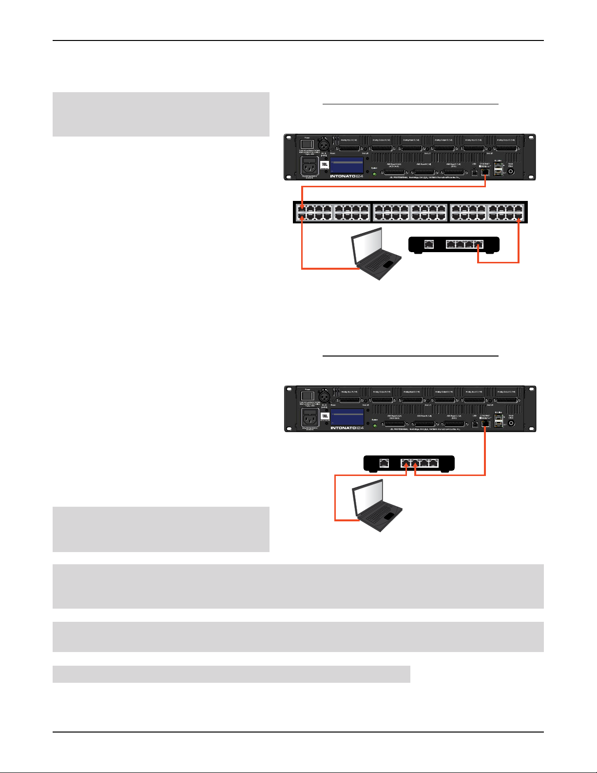
Connecting to the Network
IP: 169.254.30.21
Events:
HQ: 2:6:801B SYSTEM BOOT
WAN LAN
1 2 3 4
Ethernet Router w/DHCP
Intonato 24
Mac® or Windows®
Computer
Mac
®
Computer With Wi-Fi
IP: 169.254.30.21
Events:
HQ: 2:6:801B SYSTEM BOOT
or
Intonato 24
Wi-Fi Router w/DHCP
WAN LAN
1 2 3 4
Mac® or Windows®
Computer With Wi-Fi
Compatible Android
™
or iOS® Device
Connecting to a Wired Network Switch or Router
Connecting to the Network
NOTE: The Intonato 24 must be
connected to a DHCP-enabled network for
initial configuration and control.
1. If using a switch, connect one of the
LAN ports from a DHCP-enabled router
to one of the ports on the switch, or
connect it to another switch on the
network.
2. Connect a Cat5, Cat5e, or Cat6 Ethernet
cable to the Ethernet port on the
Intonato 24.
3. Connect the other end of the Ethernet
cable to one of the LAN ports on the
switch or router.
4. Connect your computer’s Ethernet port
to one of the other LAN ports on the
switch or router using a Cat5, Cat5e, or
Cat6 cable.
5. Apply power to the Intonato 24 and wait
for the processor to initialize. Give the
unit time to negotiate with the network
so it can be assigned an IP address. This
can take a few minutes. Look at the LCD
screen on the back of the unit to ensure
the Intonato 24 has been assigned an IP
address.
Wired Network Switch Connection
Intonato 24
IP: 169.254.30.21
Events:
HQ: 2:6:801B SYSTEM BOOT
Ethernet Switch
®
Mac
or Windows®
Computer
Ethernet Router w/DHCP
1 2 3 4
WAN LAN
Wired Network Router Connection
Intonato 24
IP: 169.254.30.21
Events:
HQ: 2:6:801B SYSTEM BOOT
Ethernet Router w/DHCP
1 2 3 4
WAN LAN
NOTE: For more information on
networking, including troubleshooting tips,
see
“Networking” on page 89.
TIP: Once connection to the network has been established using a DHCP server, the HiQnet
Mac® or Windows®
Computer
®
NetSetter™ application can be used to assign the Intonato 24 a static IP address if required for the
application. See
NOTE: The Intonato 24 can establish a network connection with the Intonato DC desktop controller
“Using HiQnet® NetSetter™” on page 92 for more information.
and control app simultaneously.
WARNING: Only connect to networks that remain inside the building.
INTONATO | 24 Operation Manual
Page 11
Connecting to the Network
Intonato 24
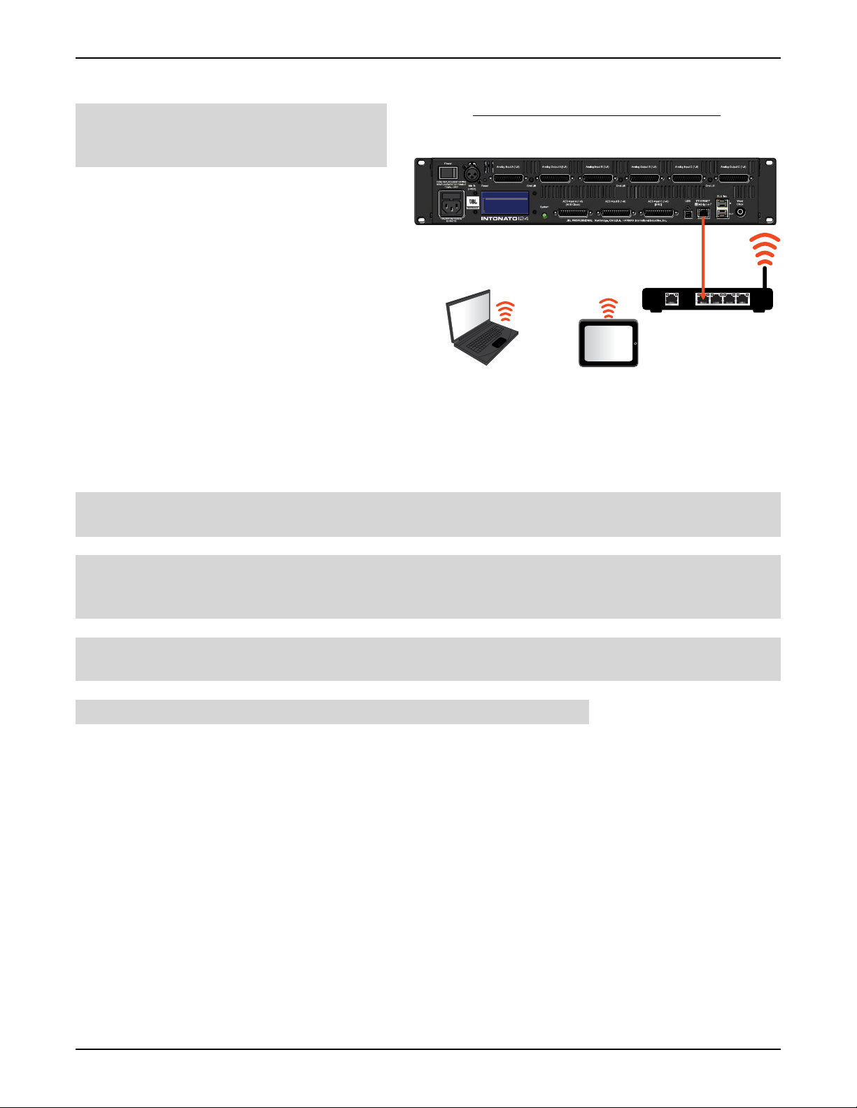
Connecting to a Wi-Fi Network Router
NOTE: The Intonato 24 must be
connected to a DHCP-enabled network for
initial configuration and control.
Wi-Fi Network Router Connection
1. Connect a Cat5, Cat5e, or Cat6 Ethernet
IP: 169.254.30.21
Events:
HQ: 2:6:801B SYSTEM BOOT
cable to the Ethernet port on the Intonato
24.
2. Connect the other end of the Ethernet
cable to one of the LAN ports on the WiFi router.
3. Connect to the Wi-Fi network using your
Wi-Fi-equipped computer or device.
4. Apply power to the Intonato 24 and wait
for the processor to initialize. Give the unit
Mac® or Windows®
Computer With Wi-Fi
Wi-Fi Router w/DHCP
or
Compatible Android
or iOS® Device
1 2 3 4
WAN LAN
™
time to negotiate with the network so it
can be assigned an IP address. This can
take a few minutes. Look at the LCD screen on the back of the unit to ensure the Intonato 24 has
been assigned an IP address.
NOTE: For more information on networking, including troubleshooting tips, see “Networking” on
page 89
.
TIP: Once connection to the network has been established using a DHCP server, the HiQnet
NetSetter application can be used to assign the Intonato 24 a static IP address if required for the
application. See
“Using HiQnet® NetSetter™” on page 92 for more information.
NOTE: The Intonato 24 can establish a network connection with the Intonato DC desktop controller
and control app simultaneously.
WARNING: Only connect to networks that remain inside the building.
Page 12
INTONATO | 24 Operation Manual
Using the Intonato 24 Control App
Using the Intonato 24 Control App
The Intonato 24 is configured using the JBL Intonato control app. For information on downloading and
installing the JBL Intonato control app, see
The following sections describe, in order, how to configure and use the Intonato 24 processor.
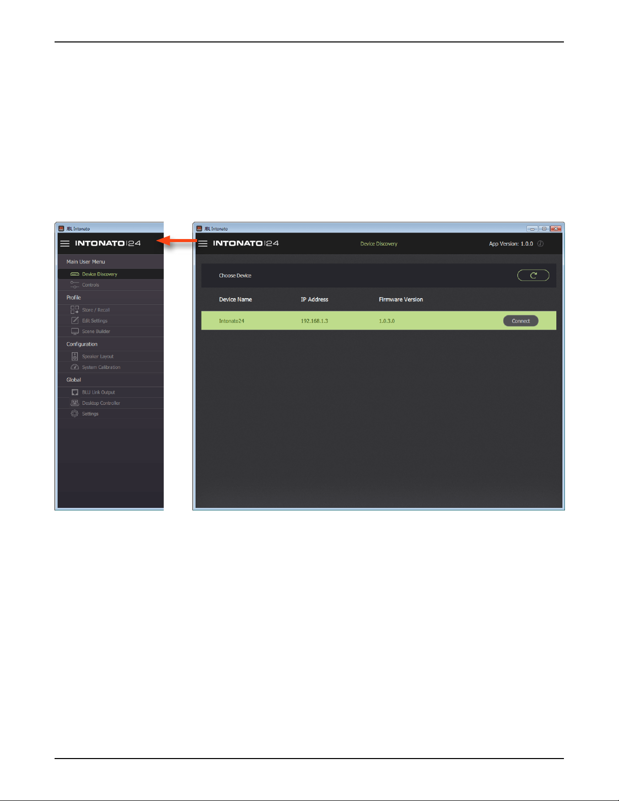
Discovering Devices on the Network
The Device Discovery screen is the first screen that appears once the JBL Intonato control app has
initialized. The app will search the network for connected Intonato 24 devices and list them on this
screen. You can always come back to this screen by selecting
Menu.
“Installing the JBL Intonato Control App” on page 10.
Device Discovery in the Main User
Refresh Button
Press this button to refresh the list of devices detected on the network.
Device List
This list displays all Intonato 24 devices detected on the network, as well as their currently configured
IP address and firmware version. Press the
INTONATO | 24 Operation Manual
Connect button to connect to a device.
Page 13
Using the Intonato 24 Control App
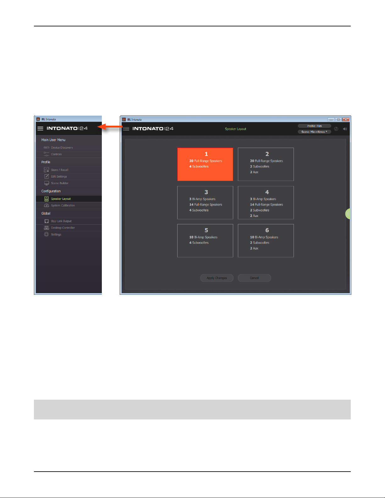
Selecting the Speaker Layout Type
The first step in configuring the Intonato 24 is to select the speaker layout that suits the application:
1. When connecting to the Intonato 24 for the first time, the control app will automatically navigate to
the Speaker Layout screen. If a speaker layout was previously selected and needs to be changed,
select
2. Select the speaker layout that suits the application.
3. Press the Apply Changes button.
Speaker Layout from the Main User Menu.
There are six speaker layout types to choose from:
1. 20 full-range speakers, 4 subwoofers
2. 20 full-range speakers, 2 subwoofers, and 2-channel aux output with talkback
3. 3 bi-amplified speakers, 14 full-range speakers, 4 subwoofers
4. 3 bi-amplified speakers, 14 full-range speakers, 2 subwoofers, and 2-channel aux output with
talkback
5. 10 bi-amplified speakers, 4 subwoofers
6. 10 bi-amplified speakers, 2 subwoofers, and 2-channel aux output with talkback
TIP: See “Application Examples” on page 44 to see example applications using some of the
speaker layouts listed above.
Page 14
INTONATO | 24 Operation Manual
Using the Intonato 24 Control App
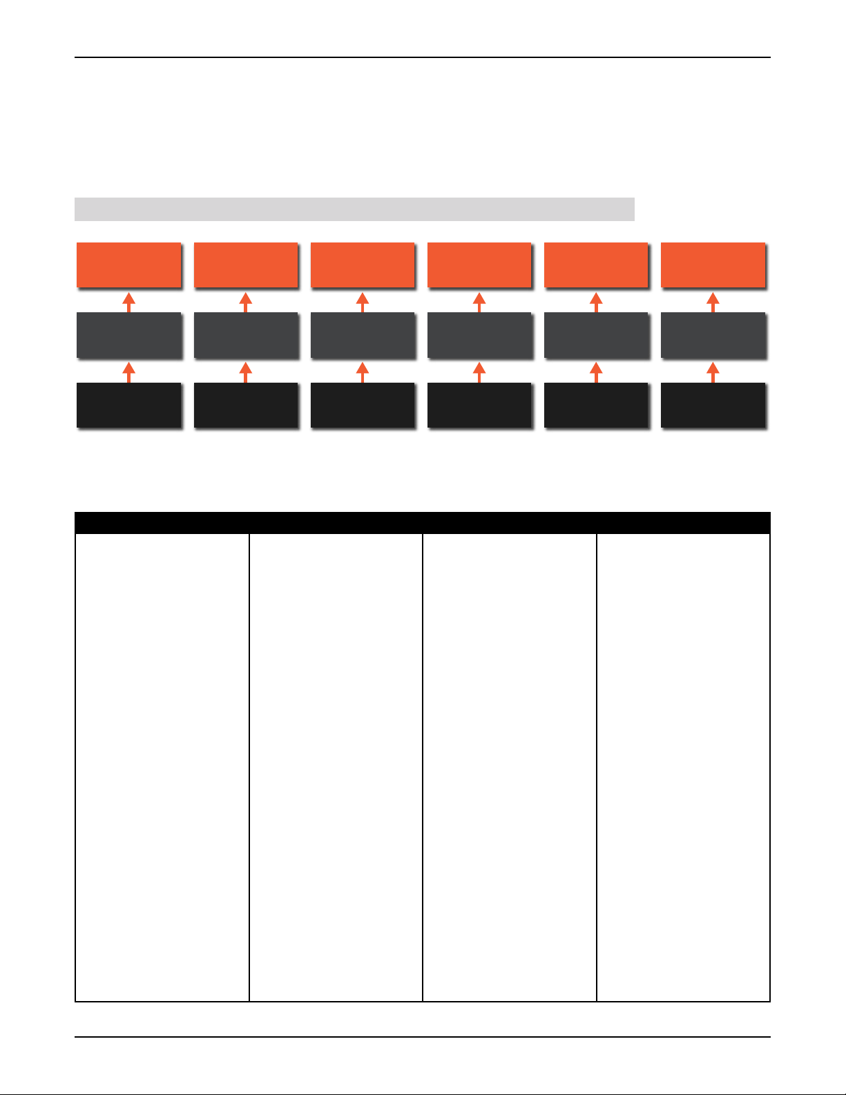
About Speaker Layouts, Proles, and Scenes
Profiles and scenes are stored to the speaker layout type selected during configuration. Up to 30
profiles can be stored to each of the six speaker layout types, and up to 30 scenes can be stored to
each of the 30 profiles (see illustration below). Although it is not typical to change the speaker layout
type once configured, unless the speaker system is being upgraded, this does provide a means to
retain profile and scene settings if the speaker layout type is changed.
NOTE: Profiles and scenes cannot be transferred between speaker layout types.
Speaker Layout
1
30 Profiles
30 Scenes
Per Profile
Speaker Layout
2
Speaker Layout
3
Speaker Layout
4
Speaker Layout
5
Speaker Layout
30 Profiles 30 Profiles 30 Profiles 30 Profiles 30 Profiles
30 Scenes
Per Profile
30 Scenes
Per Profile
30 Scenes
Per Profile
30 Scenes
Per Profile
30 Scenes
Per Profile
6
The table below shows the settings stored to the speaker layout, profiles, and scenes, and which
settings are persistent (their state/value doesn’t change as profiles and scenes are recalled, but will be
defaulted if another speaker layout type is loaded or the unit is power cycled).
Speaker Layout Profiles Scenes Persistent
• System calibration settings
(room EQ, time-alignment
delay, output level, polarity)
• Reference level user
calibration offset setting
(used to calibrate the
measured SPL readout)
• BLU link output channel
assignments
• All stored profile and scene
settings
• Input channel names,
routing, and group
assignments
• Input LFE assignments
• Input trim levels
• Output channel names,
group assignments, bass
management assignments,
and speaker tuning
selections
• Outputs assigned for
master volume control
• User EQ settings for each
output
• Analog input sensitivity,
clock source, sample rate,
and SRC enable
• AV and Aux AV delay
• Bass management
crossover frequency and
LFE low-pass frequency
• Global bass management
on/off, dim level, and
master reset level
• Aux output level and tone
(EQ) settings
• Settings for all scenes (30
per profile)
• All input and LFE mix
level settings in the Scene
Builder screen
• Master volume, dim, and
mute
• Speaker mute/solo
selections
INTONATO | 24 Operation Manual
Page 15

Using the Intonato 24 Control App
About the Aux Outputs
When speaker layout 2, 4, or 6 is selected, Intonato 24 output channels 23 and 24 are configured
to provide a stereo auxiliary feed, which can be connected to an external headphone amplifier for
recording sessions (for example, during voiceover or ADR recording sessions in an editing facility
where a mixing console is not available). The feed can also be used to send a mix to a pair of
speakers in a remote location.
A 24 x 2 mixer allows any combination of inputs to be mixed to the stereo aux output, including
downmixed surround mixes. The stereo aux output has its own level control, 3-band EQ, and AV
delay to restore “lip synchronization” with video displays.
Additionally, the XLR mic input is routed to the aux outputs and becomes active when the Talkback
button is pressed. Input 24 will automatically be switched to carry the signal from the XLR mic input.
The talkback input assignment is fixed and cannot be changed. The XLR mic input gain is fixed at 30
dB.
Page 16
INTONATO | 24 Operation Manual
Using the Intonato 24 Control App
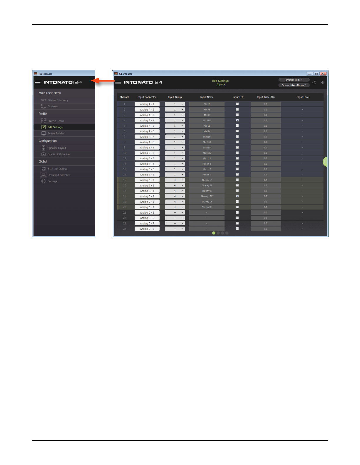
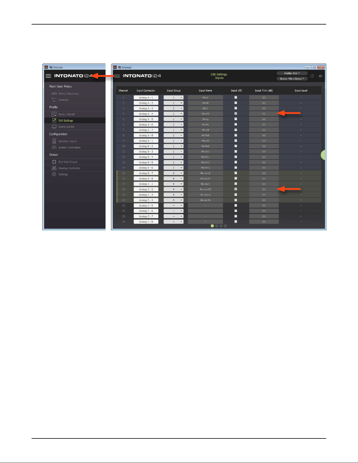
Conguring Inputs
Once the speaker layout type has been selected, it’s time to configure the inputs for the application.
The inputs can be configured by selecting
Configuration screen is the first screen displayed from this menu.
Edit Settings from the Main User Menu. The Input
Information and Navigation Bar
The bar across the top of the screen provides important feedback and access to navigation and
is available on most screens. Press the icon in the upper left-hand corner to access the Main User
Menu and navigate the various screens. The title of the current screen is displayed in the middle of the
bar. In the upper right-hand corner, the currently loaded profile and scene preset are displayed. If an
asterisk appears next to the profile or scene preset, this indicates it has been edited from the stored
values. The information icon accesses the application’s contextual help. The speaker icon can be
used to mute all outputs (with the exception of the stereo aux output).
Input Connector
From these dropdown menus, select the desired physical input to route to each corresponding
Intonato 24 input channel. There is no limitation on the mix of Analog, AES, and BLU link inputs; they
can be assigned in any order.
Input Group
Select from the 12 options available in this dropdown menu to visually group input channels by color.
Input Name
These fields allow inputs to be named to suit the application, which will simplify configuration and
operation.
Input LFE
Check any of these boxes to identify the corresponding input as an LFE channel. When checked, the
INTONATO | 24 Operation Manual
Page 17

Using the Intonato 24 Control App
input channel will be routed through the LFE low-pass filter and on to the subwoofer outputs. Any
number of inputs can be designated as LFE input channels.
NOTE: Ensure subwoofers are set to LFE mode, if applicable.
NOTE: The LFE signal level must also be set in the Scene Builder screen to feed the LFE input
signal to the subwoofer(s). See
Builder.
“Creating Scenes” on page 36 for information on using the Scene
Input Trim
Adjust these fields to trim the incoming signal level for each channel. The range is -100 to +10 dB.
Input Level
These readouts display real-time input signal level for each channel.
Master Section Tab
The tab on the right shows or hides the master section controls.
Page 18
INTONATO | 24 Operation Manual
Using the Intonato 24 Control App
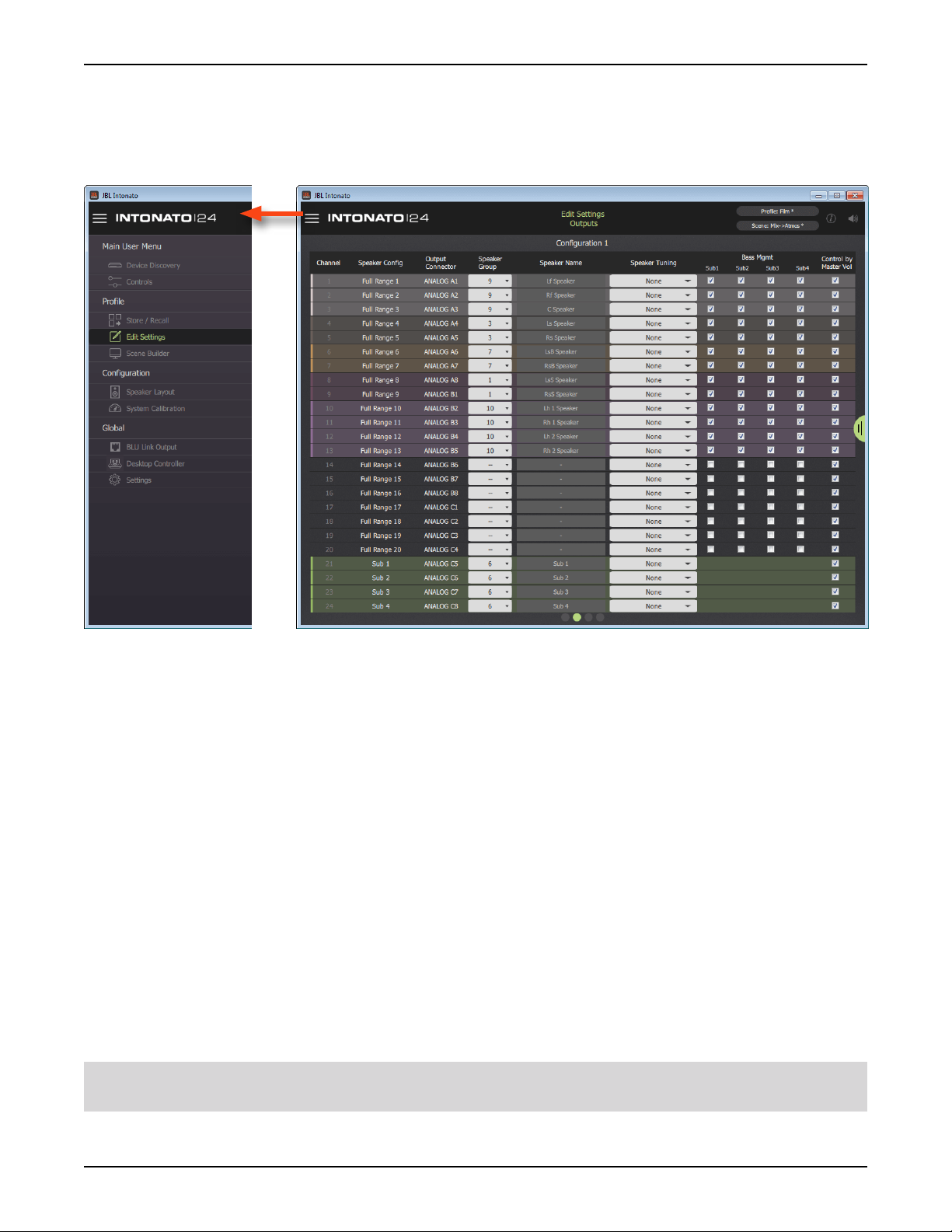
Conguring Outputs
The next step is to configure the Intonato 24 outputs. The Output Configuration screen can be
accessed by selecting
swiping or selecting the second bubble at the bottom.
Edit Settings from the Main User Menu, then going to the second screen by
Speaker Conguration
These fields display the type of output configured for each output channel per the selected speaker
layout.
Output Connector
These fields display the physical output channels as they relate to the analog D-Sub output
connectors.
Speaker Group
Select from the 12 options available in this dropdown menu to visually group speaker output channels
by color.
Speaker Name
These fields allow outputs to be named to suit the application, which will simplify configuration and
operation.
Speaker Tuning
From this dropdown menu, the speaker tuning for the connected speaker model can be selected if
available.
NOTE: The Intonato 24 comes preloaded with speaker tunings for the JBL M2 Series, 7 Series, and
various JBL subwoofers. See
“Speaker Tunings” on page 87 for more information.
INTONATO | 24 Operation Manual
Page 19

Using the Intonato 24 Control App
Bass Management (Sub1, Sub2, etc.)
Checking a checkbox in this column will configure the channel to be bass managed to the assigned
subwoofer whenever the master Bass Management button is enabled. When bass management is
enabled, a crossover will be applied to split the signal between the satellite and subwoofer speakers.
The crossover frequency can be adjusted using the Bass Management Crossover Frequency
parameter on the Utility screen.
Control by Master Volume
Each channel checked in this column will be controllable by the studio engineer when adjusting the
master volume controls (Master Volume, Dim button, and Mute button).
Master Section Tab
The tab on the right shows or hides the master section controls.
Page 20
INTONATO | 24 Operation Manual
Using the Intonato 24 Control App
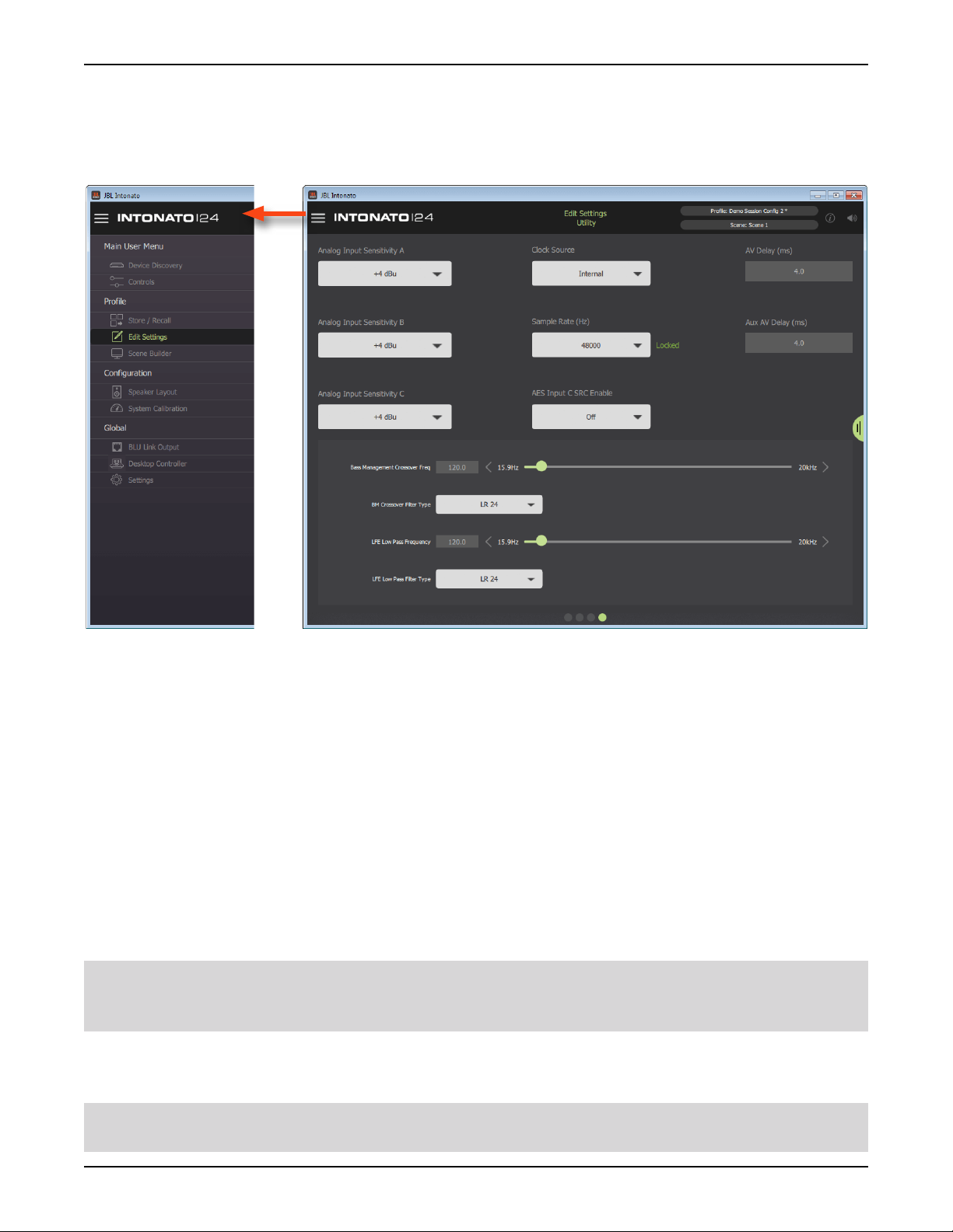
Conguring Utility Settings
The next step is to configure the Intonato 24 utility settings. The Utility screen can be accessed by
selecting
selecting the fourth bubble at the bottom.
Edit Settings from the Main User Menu, then going to the fourth screen by swiping or
Analog Input Sensitivity (A, B, and C)
These dropdown menus adjust the input sensitivity for each of the analog D-Sub input connectors.
Adjust these settings to match the source output levels for optimal signal-to-noise ratio and
headroom. There are three options to choose from:
• -10 dBV (with 18 dB of headroom)
• +4 dBu (with 20 dB of headroom)
• +8 dBu (with 24 dB of headroom)
Clock Source
This dropdown menu selects the source that will provide master clock to the Intonato 24. The options
are Internal, AES (Input 1), and Word Clock (BNC). See
for information on setting this parameter to suit the application requirements.
76
WARNING: When clocking to an AES or word clock signal, always mute the Intonato 24 outputs
before changing the external clock’s sample rate to prevent unwanted noise through the speaker
system.
“Configuring the Clock Source” on page
Sample Rate
This dropdown menu selects the internal processing sample rate.
NOTE: When slaving to an AES or word clock signal, the external clock’s sample rate will be
detected and will override this setting.
INTONATO | 24 Operation Manual
Page 21

Using the Intonato 24 Control App
NOTE: When using BLU link, all devices on the BLU link bus must be configured with the same
sample rate setting.
AES Input C SRC Enable
This dropdown menu turns sample rate conversion on AES Input C on or off. When enabled, the
SRC LED on the front panel will light. See
information on using the SRC feature.
“Configuring the Clock Source” on page 76 for more
AV Delay
This parameter applies a delay to the audio signal to compensate for latency in video displays and
restore “lip synchronization”. The AV Delay parameter affects all output channels, with the exception of
the stereo aux output, and has a range of 0–170 ms.
Aux AV Delay
This parameter applies a delay to the audio signal to compensate for latency in video displays and
restore “lip synchronization”. The Aux AV Delay parameter affects only the stereo aux output and has
a range of 0–170 ms.
Bass Management Crossover Frequency Slider
This parameter sets the crossover frequency between the satellite speakers configured for bass
management and subwoofer(s).
Bass Management Crossover Filter Type
This dropdown selects the low-pass and high-pass filter types for the bass management crossover.
The selectable options are Bessel 6, 12, 18, 24, 30, 36, 42, 48, Butterworth 6, 12, 18, 24, 30, 36, 42,
48, Linkwitz-Riley 12, 24, 36, and 48. The numerical values indicate the slope rate in dB/octave.
LFE Low Pass Frequency Slider
This parameter sets the low-pass filter frequency for LFE signals assigned to the subwoofer(s).
NOTE: Ensure subwoofers are set to LFE mode, if applicable.
LFE Low Pass Filter Type
This dropdown selects the filter type for the LFE low-pass filter. The selectable options are Bessel 6,
12, 18, 24, 30, 36, 42, 48, Butterworth 6, 12, 18, 24, 30, 36, 42, 48, Linkwitz-Riley 12, 24, 36, and
48. The numerical values indicate the slope rate in dB/octave.
TIP: When using bass management and LFE channels, it’s important to balance the bass managed
and LFE signal levels properly. See
on page 26
for more information.
“Balancing Subwoofers – Bass Management and LFE Levels”
Master Section Tab
The tab on the right shows or hides the master section controls.
Page 22
INTONATO | 24 Operation Manual
Using the Intonato 24 Control App
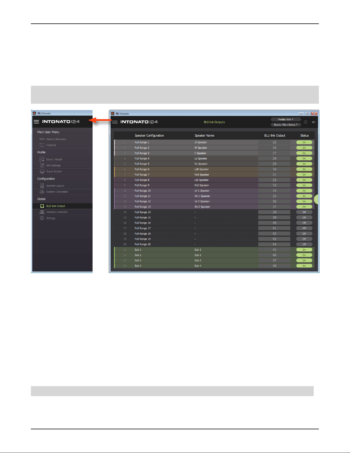
Conguring BLU link Outputs
If the application requires BLU link output from the Intonato 24, BLU link output settings should be
configured next by selecting
From the BLU Link Output screen, up to 24 BLU link channels can be assigned to the BLU link bus.
To assign BLU link output channels, select the BLU link output channel to assign then enable the
Status button for each.
NOTE: Output signals are always present on the analog D-Sub output connectors and are simply
mirrored to any assigned BLU link channels.
BLU Link Output from the Main User Menu.
Speaker Conguration
These fields display the type of output configured for each output channel per the selected speaker
layout.
Speaker Name
These fields display the name given to each speaker output.
BLU link Output
These fields select the BLU link channel to be assigned to each output.
Status
These buttons turn each BLU link output on or off. When turned off, no signal will be passed to the
BLU link bus.
NOTE: The above settings are global and will not be affected when loading profiles or scenes.
Master Section Tab
The tab on the right shows or hides the master section controls.
INTONATO | 24 Operation Manual
Page 23

Using the Intonato 24 Control App
Calibrating the System
Once configuration is complete, the next step is to run the auto-calibration process. When used in
conjunction with the included measurement microphone, a monitoring system can be automatically
calibrated to the production environment.
The auto-calibration process starts by detecting level differences between speakers in the system
and adjusting levels to match. Then, time-of-arrival differences between each speaker placement and
the listening position are detected and compensated for using delays. The final stage is to analyze
each speaker and adjust the room equalization to fine-tune each speaker’s frequency response to the
environment. Note that all parameters are also available for manual adjustment.
Follow these steps to automatically calibrate the system:
CAUTION: The use of hearing protection is recommended during the auto-calibration process.
System calibration test tones may generate sound pressure level in excess or 85 dB, which can be
painful to the ears when experienced for extended periods of time.
NOTE: The auto-calibration process cannot correct for speaker polarity issues. Ensure all balanced
audio cables and speaker wires are properly wired and connected before calibrating the system.
1. Connect the included measurement microphone to the XLR mic input using a balanced
microphone cable of suitable length and place it in a microphone stand.
2. Place the microphone at the main listening position.
3. Select System Calibration from the Main User Menu.
4. Press the Run Auto Calibration button and follow the on-screen instructions to calibrate the
system.
NOTE: The Room EQ will analyze frequencies up to 800 Hz and adjust center frequencies up to
approximately 750 Hz when running the auto-calibration process.
TIP: When running the auto-calibration process, an infinite number of mic positions can
be measured to achieve an averaged frequency response. For more accurate results, it is
recommended to measure at least three different mic positions.
5. Once system calibration is complete, make manual setting adjustments from the System
Calibration screen if required.
TIP: Any further refinements to the system’s frequency response should be made using the
User EQ so as to not disturb the calibrated Room EQ settings. See
Recommendations” on page 25
for more information.
“User EQ Refinement
TIP: The monitor system reference level readout can be calibrated using the User Calibration Offset
slider found on the Signal Generator screen. See
information on calibrating this reference level readout.
TIP: If the Intonato 24 limiters need to be used for speaker protection, the limiter threshold will need
to be calibrated. See
threshold.
Page 24
“Limiter Threshold” on page 29 for information on calibrating the limiter
INTONATO | 24 Operation Manual
“The Signal Generator Screen” on page 30 for

Using the Intonato 24 Control App
User EQ Renement Recommendations
Low Frequencies
After performing auto calibration, we recommend evaluating the low-frequency performance of the
system by listening to material with which you are familiar. While the system is designed to deliver
flat low-frequency response in the room, different room sizes require differing compensation. After
removing the energy contributed by the interactions of speakers and resonant properties of the room,
you may notice the program content lacks the expected low-frequency response.
The User EQ can be used to produce your ideal in-room response. If you notice the material lacks an
expected low-frequency contour, we recommend applying the following settings to all speakers in the
system:
• Type: Low Shelf
• Frequency: 95 Hz
• Slope: 9 dB/octave
• Gain: +2 dB to +6 dB (Apply the amount of gain required to restore the expected low-frequency
energy.)
Adjustments may vary as follows:
• Frequency: 90 Hz to 110 Hz
• Slope: From 6 dB/octave to 12dB/octave
Applying the aforementioned User EQ settings in addition to the calibrated Room EQ settings should
provide a neutral mix environment.
High Frequencies
In the midrange and high frequencies, the speaker is in control. In the low frequencies, the room is in
control. While the reflectivity or absorptive qualities of the room may affect the overall high-frequency
energy of the speaker system, the User EQ (found in the Edit Settings menu) allows project-specific
and client-specific equalization to be applied, without disturbing the Room EQ settings applied during
the auto-calibration process.
Depending on the size and acoustic characteristics of the room, reflectivity vs absorptive qualities,
and perforated-screen transmission loss, attenuation or boost of the high-frequency response may be
desirable. Additionally, the X Curve or another custom frequency-response contour may be required
for the application. This should be applied using the User EQ.
For more information on using the User EQ, see
“Adjusting User EQ” on page 32.
INTONATO | 24 Operation Manual
Page 25
Using the Intonato 24 Control App
Balancing Subwoofers – Bass Management and LFE Levels
When using bass management and LFE channels, it’s important to balance the levels between
the two properly. Up to four subwoofers may be used for bass management—extending the lowfrequency response of the speaker system. Additionally, the same subwoofers can be assigned to
reproduce the LFE (Low Frequency Effects) channels of one or more playback sources. When using a
sub for both purposes, levels should be calibrated as described below.
To calibrate bass management and LFE signal levels for the subs, follow these steps:
NOTE: Auto calibration should be performed before calibrating the bass management and LFE
levels. See
1. Ensure Bass Management is enabled and play broadband source material—with which you
are familiar—through the system. Ensure that no signal is being sent to the LFE channel. Select
System Calibration from the Main User Menu, then solo the first sub and one of the main satellite
speakers in the left-hand column.
NOTE: If using only one subwoofer, solo both the left and right front satellite speakers along with
the sub to account for the ~3 dB increase in signal level due to summation of the two satellite
speakers vs the single subwoofer.
Select the first sub from the left-hand column and adjust the sub’s
subwoofer response with the bass-managed satellite speaker(s) to produce the desired bassmanaged response. When properly balanced, the subwoofer and the speaker(s) should behave as
a single speaker with extended low-frequency response. Repeat for any additional subwoofers.
“Calibrating the System” on page 24.
Level setting to balance the
2. Once all bass management sub levels have been calibrated, un-solo the channels so that all
channels are again audible.
Page 26
INTONATO | 24 Operation Manual
Using the Intonato 24 Control App
3. Next, play some source material that includes LFE signal, and ensure the LFE signal is passing
through the system. Select
control of the LFE channel to produce the desired SPL in the room. Repeat for any additional
source LFE channels.
Edit Settings from the Main User Menu, then adjust the Input Trim
INTONATO | 24 Operation Manual
Page 27
Using the Intonato 24 Control App
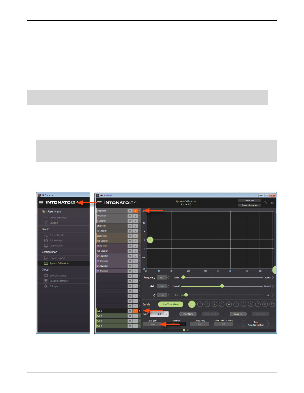
The System Calibration Screen
From the System Calibration screen, individual speaker levels, time-of arrival delay offsets, and room
EQ can be automatically calibrated and/or manually adjusted for the monitoring environment. To
access the System Calibration screen, select
System Calibration from the Main User Menu.
Channel Selection (Leftmost Column)
This column allows an output channel to be selected for editing.
Mute and Solo Buttons
The Mute (M) and Solo (S) buttons can be used to mute or solo output channels. Multiple channels
can be muted or soloed simultaneously.
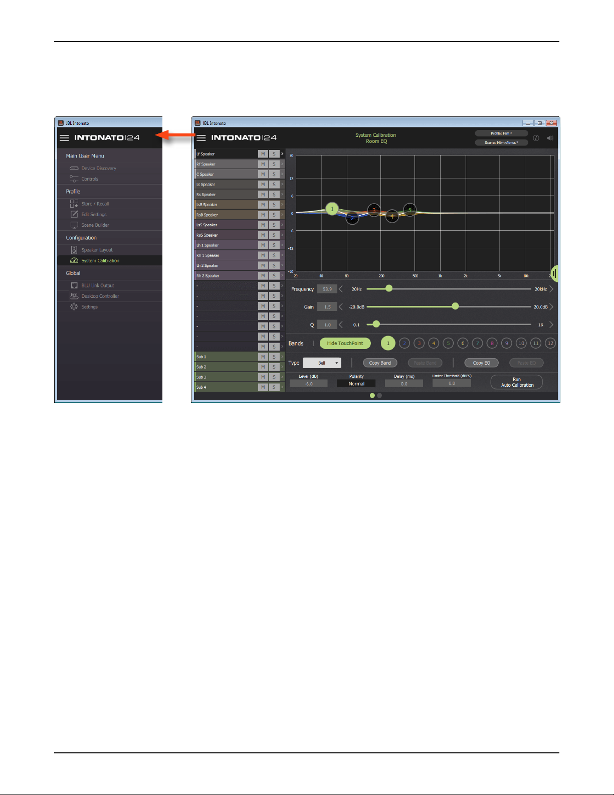
Graph
This graph displays a graphical representation of the Room EQ curve, with touchpoints that can be
selected and dragged to adjust settings graphically.
Frequency Slider
This parameter adjusts the frequency of the selected band. Values can be adjusted by dragging the
slider, pressing the arrows, or entering a value directly in the numeric field.
Gain Slider
This parameter adjusts the gain of the selected band.
Q Slider
This parameter adjusts the width of the selected band.
Show/Hide TouchPoint Button
This button toggles visibility of the band-numbered touchpoints in the graph.
Page 28
INTONATO | 24 Operation Manual
Loading...