

Page 1
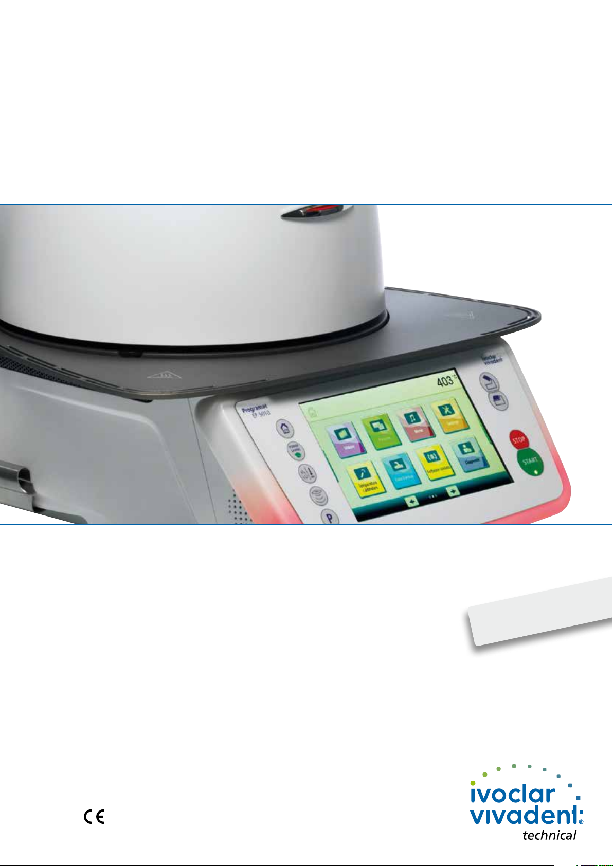
Programat® EP 5010
Operating Instructions
Valid from
software V2.0
1
Page 2

2
Page 3

Table of Contents
List of parts 4
1. Introduction / Signs and Symbols 7
1.1 Introduction
1.2 Signs and symbols used in these Operating Instructions
1.3 Notes regarding the Operating Instructions
1.4 Notes on the different voltage versions
1.5 Notes on the images in these Operating Instructions
2. Safety First 9
2.1 Indications
2.2 Health and safety instructions
3. Product Description 14
3.1 General
3.2 Hazardous areas and safety equipment
4. Installation and Initial Start-Up 15
4.1 Unpacking and checking the contents
4.2 Selecting the location
4.3 Assembly
4.4 Removing the furnace head
4.5 Initial start-up
5. Operation and Configuration 23
5.1 Introduction to the operation
5.2 Firing programs and programming options
5.3 Press programs and programming options
5.4 Advanced functions of the furnace (e.g. user code)
6. Practical Use 68
6.1 Firing procedure with an Ivoclar Vivadent program
6.2 Firing procedure with an individual program
6.3 Press procedure with an Ivoclar Vivadent program
6.4 Press procedure with an individual program
7. Maintenance, Cleaning and Diagnosis 77
7.1 Monitoring and maintenance
7.2 Cleaning
7.3 Service note
7.4 Idle mode
7.5 Power-saving mode
7.6 Replacing the press plunger
8. What if... 81
8.1 Error messages
8.2 Additional error messages
8.3 Technical malfunctions
8.4 Repair
8.5 Resetting to factory settings
9. Product Specifications 88
9.1 Delivery form
9.2 Technical data
9.3 Acceptable operating conditions
9.4 Acceptable transportation and storage conditions
10. Appendix 90
10.1 Firing program table
10.2 Press program table
3
Page 4
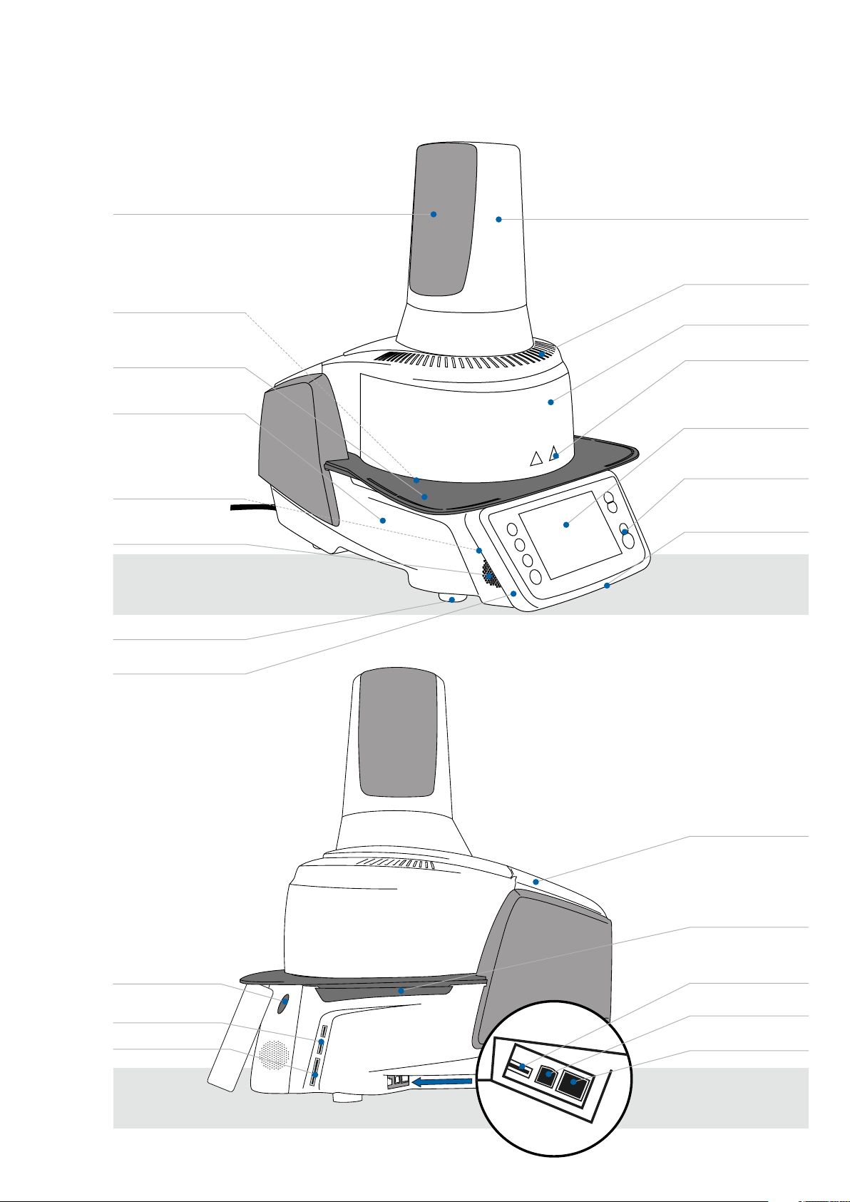
List of parts
B Ventilation grid press drive
1 Screw for
cooling tray
2 Cooling tray
3 Furnace base
housing
4 Audio ports
(in / out)
5 Speaker
A Press drive cover
7 Air vents furnace head
8 Furnace head housing
9 Warnings
10 Touch screen
11 Keypad
12a Optical Status Display
(OSD)
6 Furnace feet
12b Progress display
13 Operating
unit fixture
14 USB connections
15 Card reader
16 Covering hood for
head opening mechanism
17 Air vents
furnace base
18 USB connection
19 USB device
20 Ethernet connection
4
Page 5
21 Insulation
22 Firing plate
23 Firing plate holder
24 Frame plate
List of parts
25 QTK2 heating muffle
26 Sealing rims of furnace head
27 Infrared camera
28 Sealing surface
29 On / Off switch
30 Power socket
31 Power cord
32 Rating plate
C Screw for
press drive cover
36 Covering hood for head
opening mechanism
37 Connection cover
38 Screw for connection cover
39 Air vents rear panel
40 Heating element fuse
41 Vacuum hose connection
42 Vacuum hose
34 Vacuum pump socket
33 Vacuum pump fuse
35 Power cord for vacuum pump
5
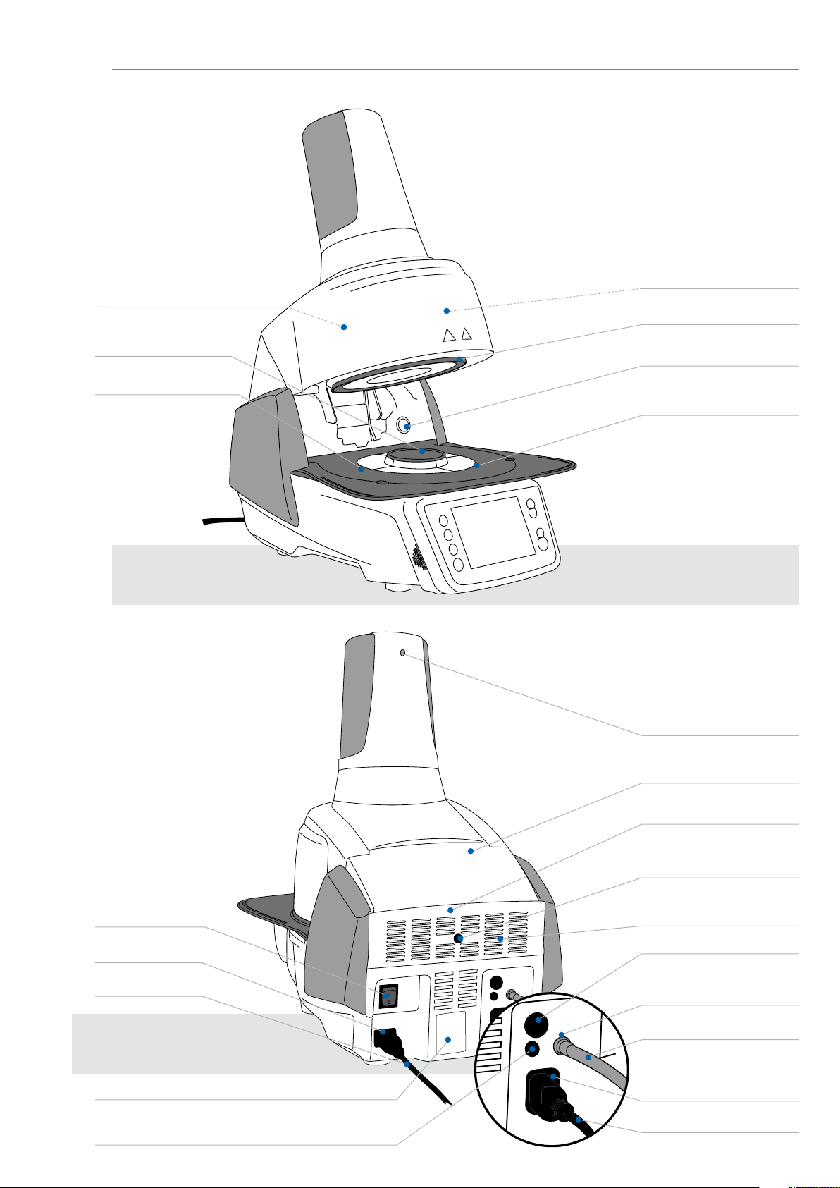
Page 6
List of parts
43 Furnace head mounting
44 Furnace head
release
45 Heater cable
46 Thermocouple cable
47 Furnace head vacuum hose
56 Press drive cable
48 Plug fuse
49 Heater plug
50 Heater plug socket
51 Thermocouple plug
52 Thermocouple
plug socket
53 Furnace head vacuum
connection
54 Press drive plug
55 Press drive socket
60 Fan 62 Cover for press
electronics
61 Press electronics
67 USB download cable 68 Programat Firing Tray
Kit 2
69 Programat USB
stick
70 Automatic Temperature
Checking Set ATK2 (test set)
63 Split taper socket
for press plunger
64 Terminal screw for
press plunger
65 Press plunger
66 Head insulation
71 Cooling grid
6
Page 7
1. Introduction / Signs and Symbols
1.1 Introduction
Dear Customer
®
Thank you for having purchased the Programat
applications. The furnace has been designed according to the latest industry standards. Inappropriate use may result in
certain risks. Please observe the relevant safety instructions and read these Operating Instructions carefully.
We hope that you will enjoy working with the Programat EP 5010.
1.2 Signs and symbols used in these Operating Instructions
The signs and symbols used in these Operating Instructions facilitate the finding of important points and have the following
meanings:
Symbol Note
Risks and dangers
EP 5010. It is a state-of-the-art press and ceramic furnace for dental
Important information
Contraindication
Burn hazard
Risk of crushing
The Operating Instructions must be read.
1.3 Notes regarding the Operating Instructions
Furnace concerned: Programat EP 5010
Target group: Dental technicians, dental professionals
These Operating Instructions facilitate the correct, safe and economic use of the furnace. Should you lose these Operating
Instructions, extra copies can be ordered at a nominal fee from your local Ivoclar Vivadent Service Center or downloaded
from www.ivoclarvivadent.com.
7
Page 8

1. Introduction / Signs and Symbols
1.4 Notes on the different voltage versions
The furnace is available in different voltage versions:
– 110 – 120 V / 50 – 60 Hz
– 200 – 240 V / 50 – 60 Hz
In the Operating Instructions, the furnace is described in the 200 – 240 V voltage version. Please note that the voltage
range shown on the images (e.g. rating plate) may differ depending on the voltage version of your furnace.
1.5 Notes on the images in these Operating Instructions
All images and illustrations in these Operating Instructions are used for exemplification and the details are not authoritative
for the construction of the furnace. They are symbols which may slightly differ from the original, e.g. due to simplification.
8
Page 9

2. Safety First
This chapter is especially important for individuals who work with the Programat EP 5010 or who have to carry
out maintenance or repair work. This chapter must be read and the corresponding instructions followed!
2.1 Indications
The Programat EP 5010 must only be used to press and fire dental ceramic materials and it should be used for this purpose
only. Other uses than the ones stipulated, e.g. cooking of food, firing of other materials etc., are contraindicated. The
manufacturer does not assume any liability for damage resulting from misuse. The user is solely responsible for any risk
resulting from failure to observe these Instructions.
Further instructions to assure proper use of the furnace:
– The instructions, regulations and notes in these Operating Instructions must be observed.
– The instructions, regulations and notes in the material’s Instructions for Use must be observed.
– The system must be operated under the indicated environmental and operating conditions (Chapter 9.3).
– The Programat EP 5010 must be properly maintained.
Risks and dangers
The furnace head should not be removed from the furnace base as long as
the furnace head is connected by means of the heater cable.
Make sure that no liquids or other foreign substances enter the furnace.
Burn hazard: Never place objects in the firing chamber by hand, since there is
a burn hazard. Always use the tongs (accessories) supplied for this purpose.
Never touch the hot surface of the furnace head, as there is a burn hazard.
Do not carry the furnace by the cooling tray.
9
Page 10
2. Safety First
The furnace head must not be carried by holding the cables, as there is a
risk of damaging the cables and the corresponding connections.
The furnace head has an electric drive and must be operated by means of
the electronic controls. Never open the furnace head by hand, since the
mechanism will be damaged.
The furnace must not be operated if the quartz tube or the insulation in the firing chamber is damaged. There
is a risk of electric shock upon contact with the heating wire. Avoid damage of the insulation by contact with
the investment tongs or firing tongs.
Contraindications
Firing trays must not be placed in the area surrounding the firing plate, since
this will obstruct the closing of the furnace head.
Foreign objects must not be placed on the furnace head or the air vents.
Make sure that no liquids or other foreign objects enter the air vents, since
this may result in an electric shock.
10
Never use the furnace without a firing plate.
Page 11
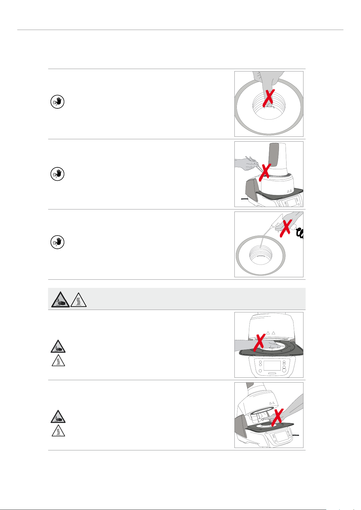
Do not touch the thermocouple or the quartz tube in the firing chamber.
Avoid contact with the skin (grease contamination), as the parts will be
prematurely damaged.
Do not insert any foreign objects into the air vents. There is a risk of
electric shock.
2. Safety First
This product contains ceramic fibres and may release fibre dust. Do not use
compressed air thus distributing the dust in the environment and observe
the additional notes on page 13.
Risk of crushing / burn hazard
Never reach under the furnace head with the hand or other parts of the
body during operation. There is a risk of burning and crushing.
Never reach inside the rear cover with the hand or particularly with the
fingers. There is a risk of crushing.
11
Page 12

2. Safety First
2.2 Health and safety instructions
This furnace has been designed according to EN 61010-1 and has been shipped from the manufacturer in excellent
condition as far as safety regulations are concerned. To maintain this condition and to ensure risk-free operation, the user
must observe the notes and warnings contained in these Operating Instructions.
– It is important that the user becomes familiar with the warnings and operating conditions to prevent injury to personnel
or damage to materials. The manufacturer is not responsible for damage resulting from misuse or failure to observe the
Operating Instructions. Warranty claims cannot be accepted in such cases.
– Before switching the furnace on, make sure that the voltage indicated on the rating plate complies with your local
power supply.
– The mains socket must be equipped with a residual current operated device (FI).
– The power plug acts as a circuit breaker and may only be connected with an easy-to-access power socket with protec-
tive contact.
– Only use the supplied original power cord. Do not use an inadequately measured replacement.
– Place the furnace on a fire-proof table: Observe local regulations (e.g. distance to combustible substances or objects,
etc.).
– Always keep the air vents at the rear of the furnace free from obstruction.
– Do not touch any parts that become hot during operation. Burn hazard!
– When removing hot components from the firing chamber (e.g. firing plate, firing tray), make sure not to place them on
a flammable surface!
– Clean furnace only with a soft, dry cloth. Do not use solvents! Disconnect the power plug before cleaning and allow the
furnace to cool down!
– The furnace must be cool before it is packed for transportation.
– Use original packaging for transportation purposes.
– Before calibration, maintenance, repair or change of parts, the power must be disconnected and the furnace has to be
cool if it has to be opened.
– If calibration, maintenance or repair has to be carried out with the power connected and the furnace open, only
qualified personnel who are familiar with the risks and dangers may perform the procedures.
– After maintenance, the required safety tests (high voltage resistance, protective conductor) must be carried out.
– Make sure that only fuses of the indicated type and rated current are used as replacements.
– If it is assumed that safe operation is no longer possible, the power must be disconnected to avoid accidental operation.
Safe operation is no longer possible if
– the furnace is visibly damaged;
– the furnace does not work;
– the furnace has been stored under unfavourable conditions over an extended period of time.
– Use only original spare parts.
– The temperature range for faultless operation is +5 °C to +40 °C.
– If the furnace has been stored at very low temperatures or high atmospheric humidity, it must be dried or left to adjust
to the room temperature for approx. 4 hours prior to connecting power.
– The furnace is tested for use at altitudes of up to 2,000 m above sea level.
– The furnace may only be used indoors.
– Before leaving the factory, the furnace functions were tested for several hours. It is therefore possible that these tests
have caused slight discolouration of the insulation. Nevertheless, your Programat EP 5010 is still a brand new furnace.
12
Page 13

Any disruption of the protective conductor either inside or outside the furnace or any loosening of the
protective conductor may lead to danger for the user in case of a malfunction. Deliberate interruptions are not
permissible.
Materials developing harmful gases must not be fired.
Warnings regarding the removal of the heating muffle
This product contains ceramic fibres and may release fibre dust. Fibre dust has proved to be carcinogenic in
animal experiments. The heating muffle may only be dismounted by a qualified After Sales Service Center.
Information regarding the Safety Data Sheet is also available from your After Sales Service Center.
Disposal:
The furnace must not be disposed with the common domestic waste. Please correctly dispose of old furnaces
according to the corresponding EU council directive. Information regarding disposal can be found on the
respective national Ivoclar Vivadent website.
2. Safety First
13
Page 14

3. Product Description
3.1 General
The Programat EP 5010 is a state-of-the-art press and ceramic furnace for dental applications. The firing chamber may be
heated up to max. 1200 °C by means of a heating element. The pressure for the press procedure is generated by a press
drive. Furthermore, the firing chamber has been designed in such a way that a vacuum may be created with a vacuum
pump. The firing / press programs are controlled with the corresponding electronic controls and software. Additionally, the
set and actual temperatures are continuously compared.
The Programat EP 5010 consists of the following components:
– furnace base with electronic controls
– furnace head with firing chamber and press drive
– cooling tray
– firing plate
– power cord and hose for vacuum pump.
3.2 Hazardous areas and safety equipment
Description of the risk areas of the furnace:
Hazardous area Type of risk
Firing chamber Burn hazard
Opening / closing mechanism Risk of crushing
Electric components Risk of electric shock
Description of the safety equipment of the furnace:
Safety equipment Protective effect
Protective conductor Protection from electric shock
Electric fuses Protection from electric shock
Furnace housing and covers Protection from electric shock, burning and crushing
14
Page 15
4. Installation and Initial Start-Up
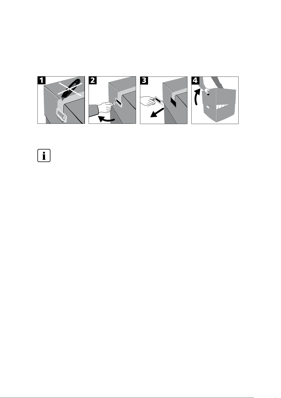
4.1 Unpacking and checking the contents
Remove the furnace components from their packaging and place the unit on a suitable table. Please observe the instructions
on the outer packaging.
There are no special transportation grips on the furnace. Support the bottom of the furnace to carry it. Check the delivery
for completeness (see delivery form in Chapter 9) and transportation damage. If parts are damaged or missing, contact
your local Ivoclar Vivadent Service Center.
We recommend keeping the original packaging for future service and transportation purposes.
4.2 Selecting the location
Place the furnace on a flat table using the rubber feet. Make sure that the furnace is not placed in the immediate vicinity of
heaters or other sources of heat. Make sure that air may properly circulate between the wall and the furnace. Also ensure
that there is enough space between the furnace and the user, as the furnace releases heat during the opening of the furnace
head.
The unit should neither be placed nor operated in areas where there is an explosion hazard.
15
Page 16
4. Installation and Initial Start-Up
4.3 Assembly
Assembling the furnace is very easy and involves only few steps. Before you start assembling the furnace, make sure that
the voltage indicated on the rating plate (32) complies with the local power supply. If this is not the case, the furnace must
not be connected!
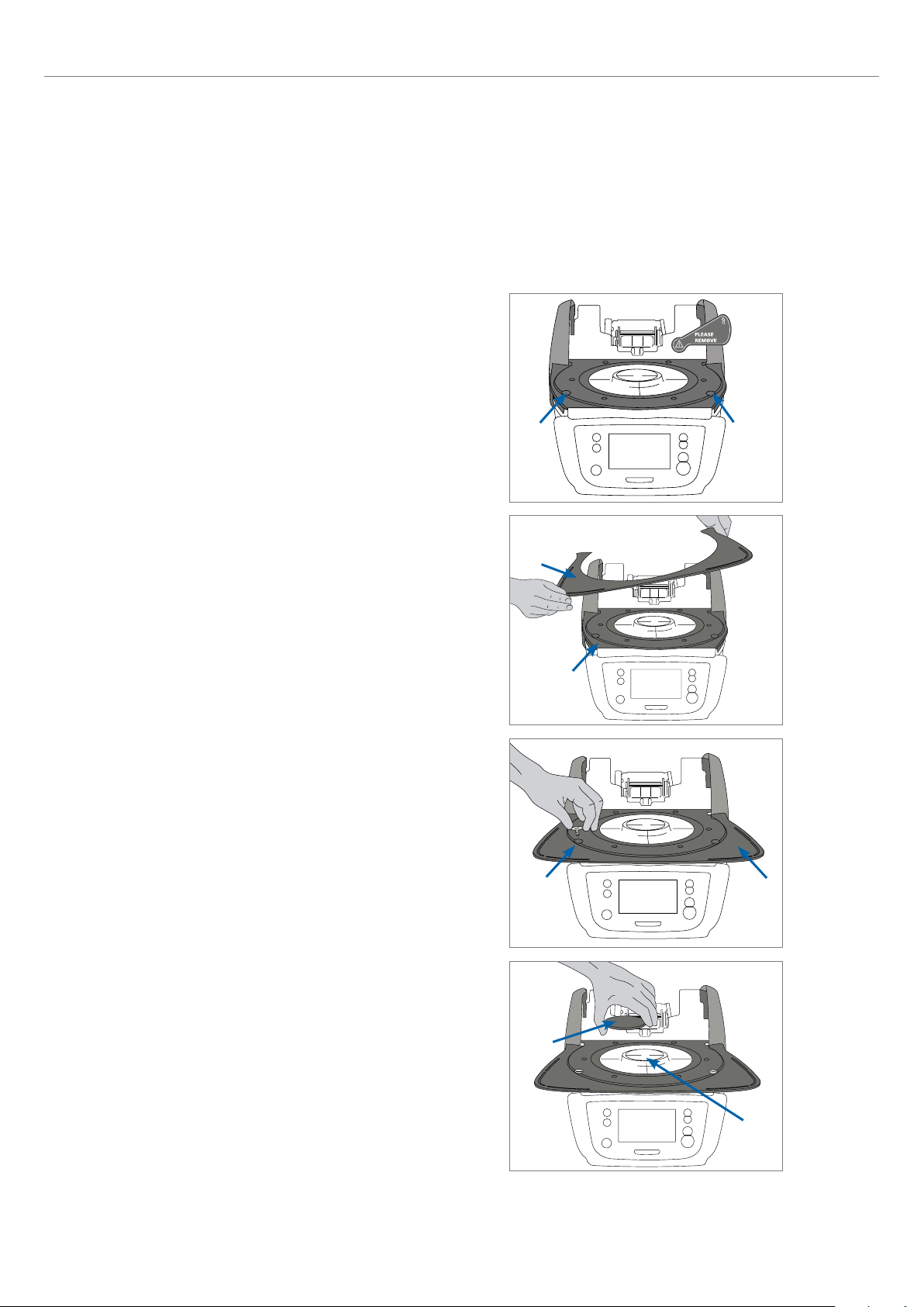
Step 1:
Mount the cooling tray (2).
Remove the two screws for the cooling tray and
the transport protection for the infrared camera.
Place the cooling tray (2) on the frame plate (24). Make sure that the
cooling tray is correctly positioned on the frame plate.
Secure the cooling tray with the two screws (1).
1
2
24
1
16
Step 2:
Place the firing plate.
Place the firing plate (22) on the firing plate holder (23). If placed
correctly, the bottom of the firing plate is automatically centred in
the firing plate holder.
1
22
2
23
Page 17
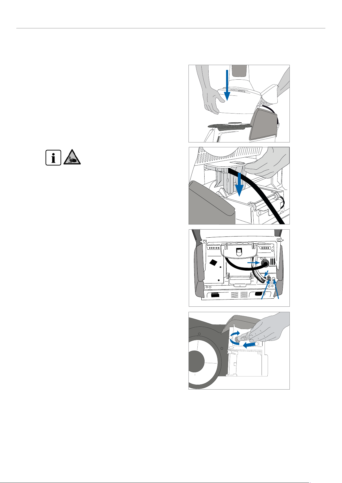
Step 3:
Mount the furnace head.
The furnace head is best mounted with the rear panel of the furnace
pointing towards the user. Lift the furnace head with both hands
(see picture) and carefully position it on the furnace head mounting.
4. Installation and Initial Start-Up
Position the furnace head mounting as shown in
the picture until the furnace head audibly snaps
into place. Make sure that the firing plate and the
insulation are not damaged by mounting the
furnace head.
Step 4:
Connect the cables.
Connect the cables of the furnace head with the furnace base.
Proceed as follows:
– Connect the vacuum hose.
– Insert the thermocouple plug (make sure that the polarity of the
plug is correct).
– Insert the press drive plug.
– Insert the heater plug.
1. Insert the heater plug into the intended connector.
2. Secure the heater plug by rotating it 45° until it snaps into
place.
49
54
51
2
1
53
17
Page 18
4. Installation and Initial Start-Up
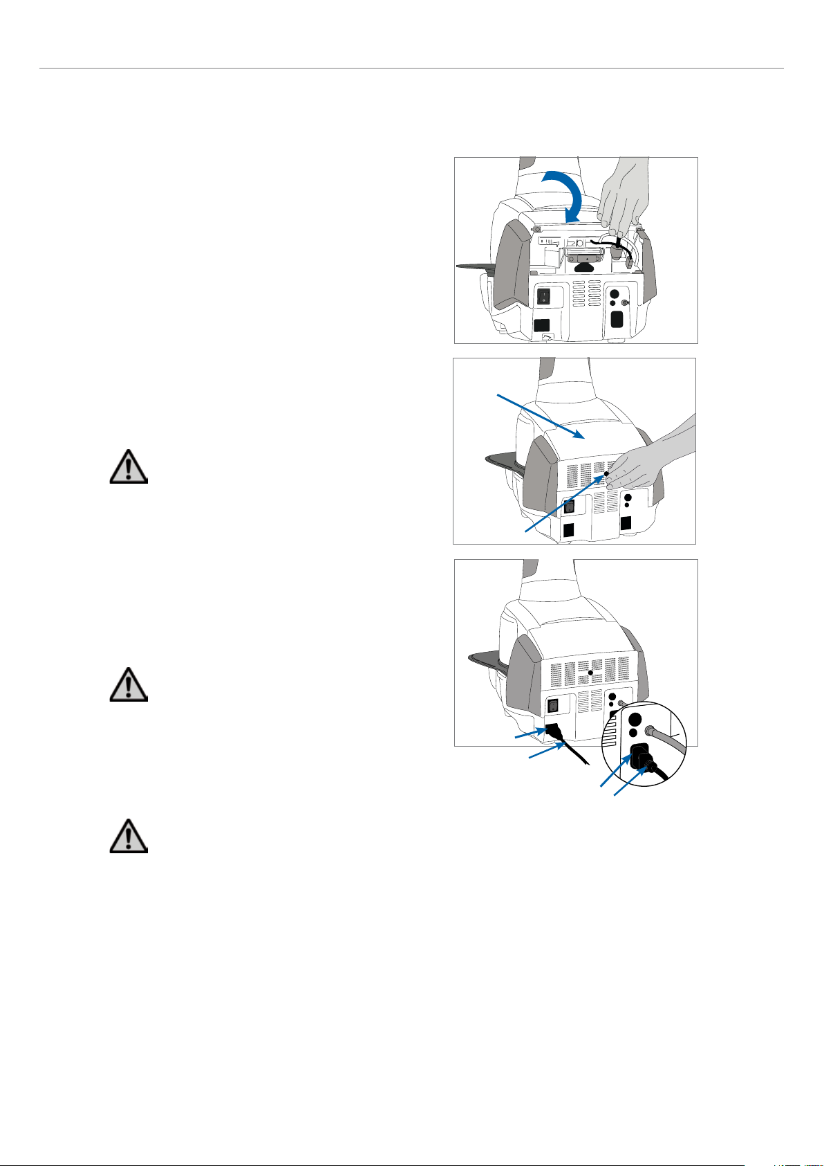
Step 5:
Close the covering hood.
Once all cables are properly connected to the furnace base, close the
covering hood over the connections.
Step 6:
Mount the connection cover.
Mount the connection cover and secure it with the fastening screw.
Make sure that the lateral catch springs snap into place when
mounting the connection cover.
The furnace must only be operated with the covering
hood closed and the connection cover mounted!
32
Step 7:
Establish additional connections.
Connecting the power
Please make sure that the voltage indicated on the rating plate
complies with the local power supply. Subsequently, connect the
power cord with the power socket of the furnace.
The furnace must only be operated with the supplied
power cord!
Connecting the vacuum pump
Connect the vacuum pump plug with the vacuum pump socket.
We recommend using only a vacuum pump from Ivoclar Vivadent
(VP4 / VP5), since these pumps are especially coordinated with the
press furnace. If other pumps are used, please observe and do not
exceed the maximum power consumption.
Do not shorten the vacuum hose! The minimum length of
the vacuum hose is 1.6 m.
33
25
26
29
30
18
Page 19
4.4 Removing the furnace head
Before the connection cover and the covering hood are removed, the
furnace has to be switched off and the power cord disconnected
from the power socket.
1. Loosen and remove the knurled screw of the connection cover.
2. Dismount the connection cover.
3. Open the covering hood.
4. Release the heater plug and disconnect it with a 45° anti-
clockwise rotation.
5. Disconnect the press drive plug.
6. Disconnect the thermocouple plug.
7. Disconnect the vacuum hose.
8. Press the leaf spring with a finger, lift off the furnace head at the
same time and remove it.
Make sure that the furnace head has completely
cooled down before it is removed (fire hazard).
4. Installation and Initial Start-Up
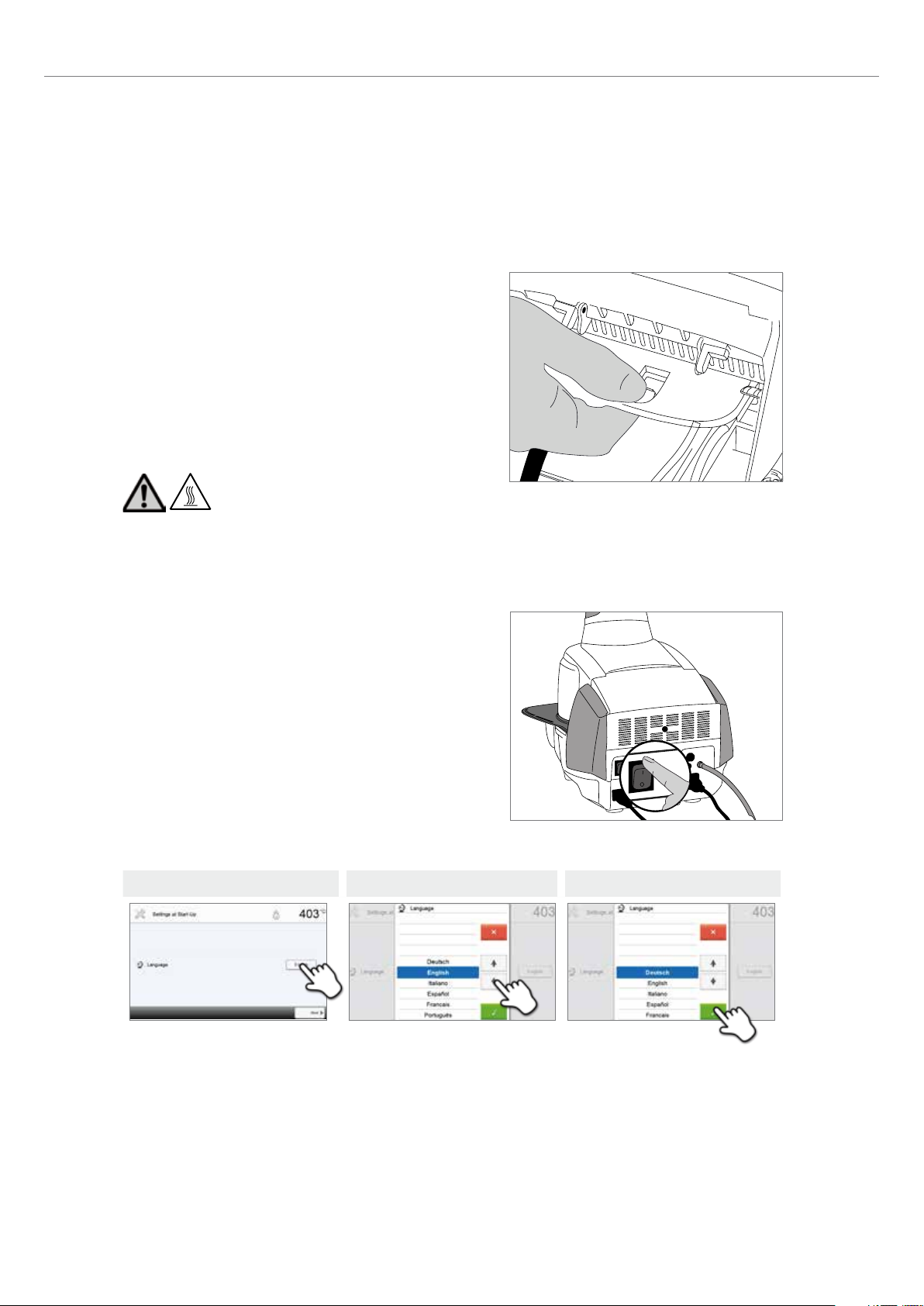
4.5 Initial start-up
1. Connect the power cord with the wall socket.
2. Switch the On / Off button at the rear of the furnace to position I.
4.5.1 Basic settings upon initial start-up
Upon the initial start-up of the new furnace, a number of basic
settings are required. These settings will be stored and will not appear
anymore upon the following starting procedure.
Step 1:
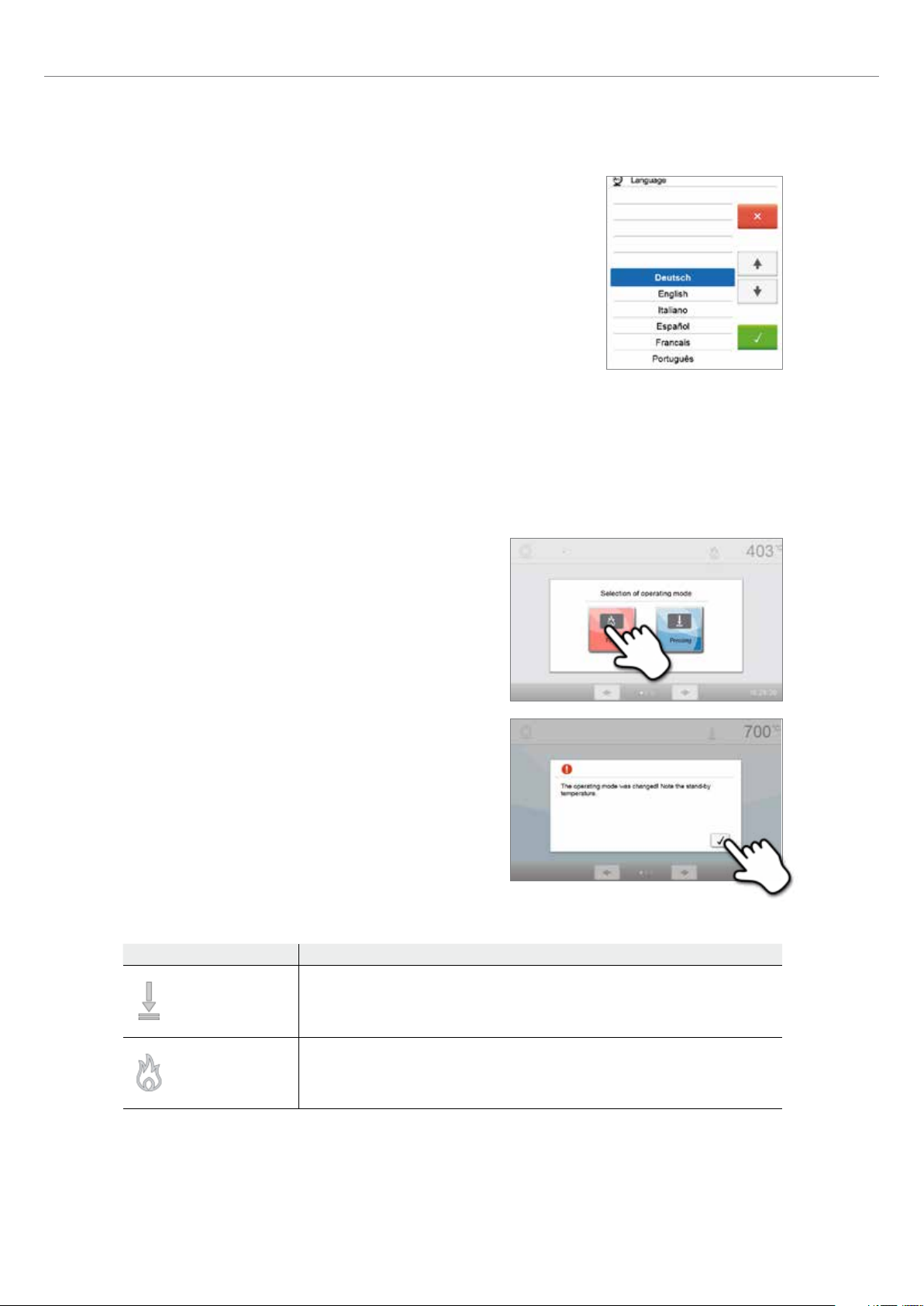
Select the language.
The touch buttons (display keys) can be operated by tapping the display.
Step 1 Step 2 Step 3
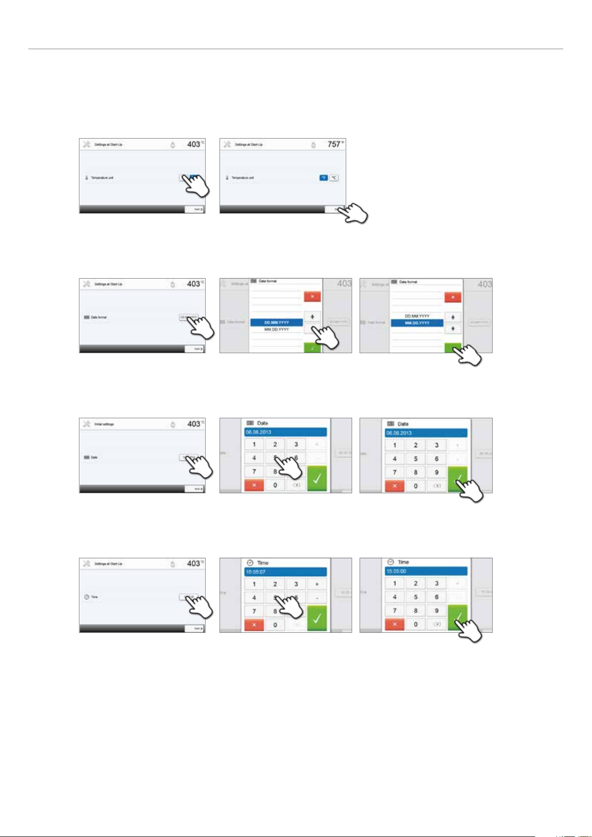
Select the desired language using the [Arrow up / down] buttons. Confirm the entry with the green button. The [Next]
button is used to reach the next entry screen.
19
Page 20
4. Installation and Initial Start-Up
Step 2:
Select the desired temperature unit.
The [Next] button is used to reach the next entry screen.
Step 3:
Select the date format.
Confirm the entry with the green button. The [Next] button is used to reach the next entry screen.
Step 4:
Set the date (day, month, year).
Confirm the entry with the green button. The [Next] button is used to reach the next entry screen.
Step 5:
Set the time (hours, minutes, seconds).
Confirm the entry with the green button. The [Next] button is used to reach the next entry screen.
20
The initial start-up and entry of the basic settings are now complete. The furnace will now automatically conduct a selftest.
Page 21
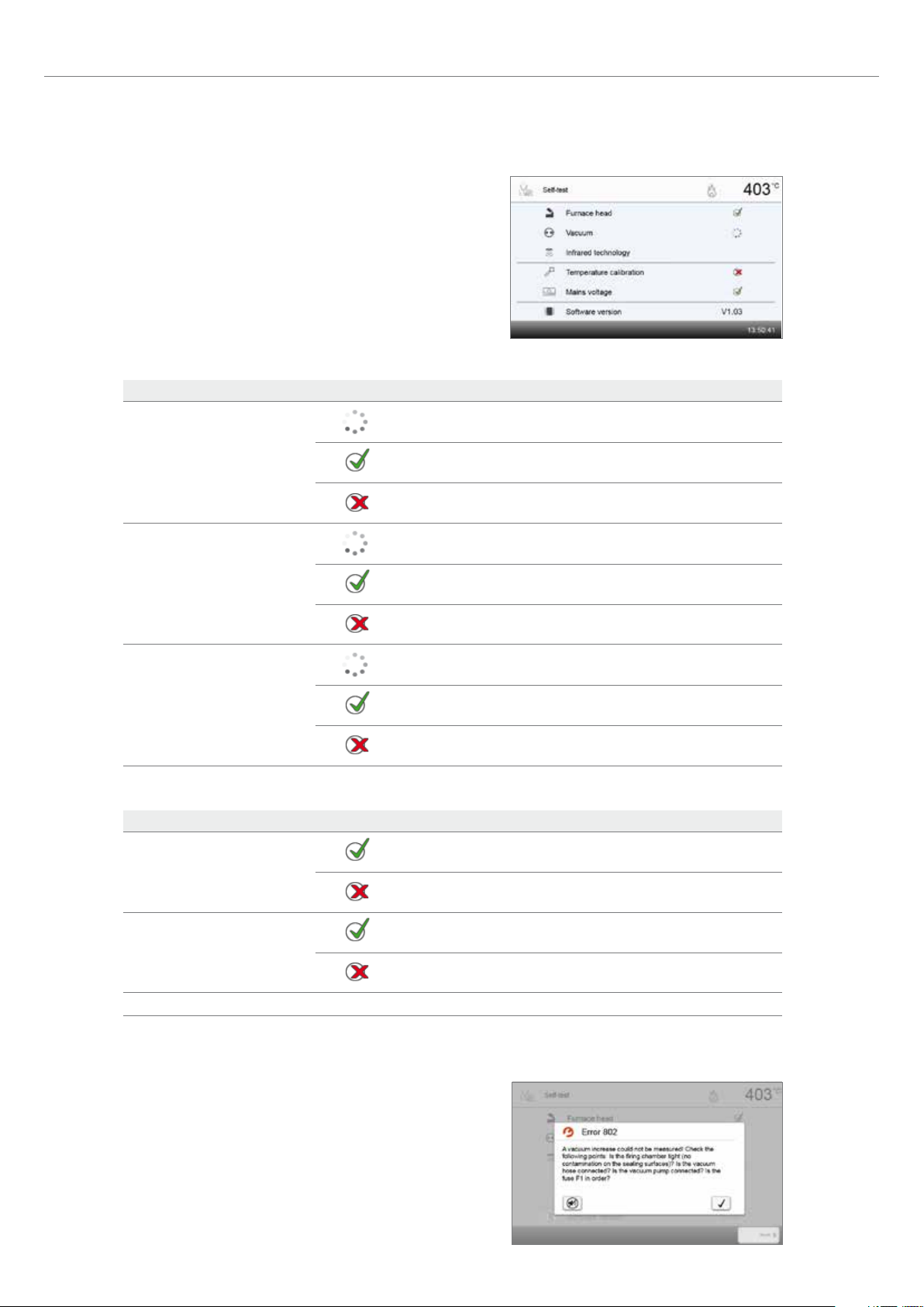
4.5.2 Start screen and self-test
Immediately after switching on, the display briefly shows the start
screen. Subsequently, the furnace conducts an automatic self-test.
The performance of all furnace components is automatically checked.
The following functions are checked:
Function
The furnace head test is in progress.
4. Installation and Initial Start-Up
Furnace head test
Vacuum test
IRT test
The following information is displayed:
Information
Temperature calibration
The furnace head test was successful.
The furnace head test failed. Please note the error message on the
display.
The vacuum test is in progress.
The vacuum test was successful.
The vacuum test failed. Please note the error message on the display.
The IRT test is in progress.
The IRT test was successful.
The IRT test failed. Please note the error message on the display.
Temperature calibration of the furnace is not required.
Some time has passed since the last calibration.
Please conduct a calibration procedure.
The power supply voltage is in the acceptable range.
Power supply
The power supply is outside the acceptable range.
Software version The currently installed software version is displayed.
If the self-test has been successful, the furnace will automatically display the screen to select the desired operating mode
(firing / pressing).
If the program recognizes a malfunction during the test, a
corresponding error message with the corresponding rectification
information appears on the display.
The acoustic signal and the error message can be acknowledged with
the corresponding buttons.
21
Page 22

4. Installation and Initial Start-Up
Press the [Next] button to confirm the self-test.
Before the first firing, the firing chamber should be dehumidified using the dehumidification program (see Chapter
5.4 for details).
Please note that the furnace may require a certain acclimation time after having been set-up. Particularly if the
furnace was exposed to considerable temperature changes (water condensation).
22
Page 23
5. Operation and Configuration
5.1 Introduction to the operation
5.1.1 Control unit
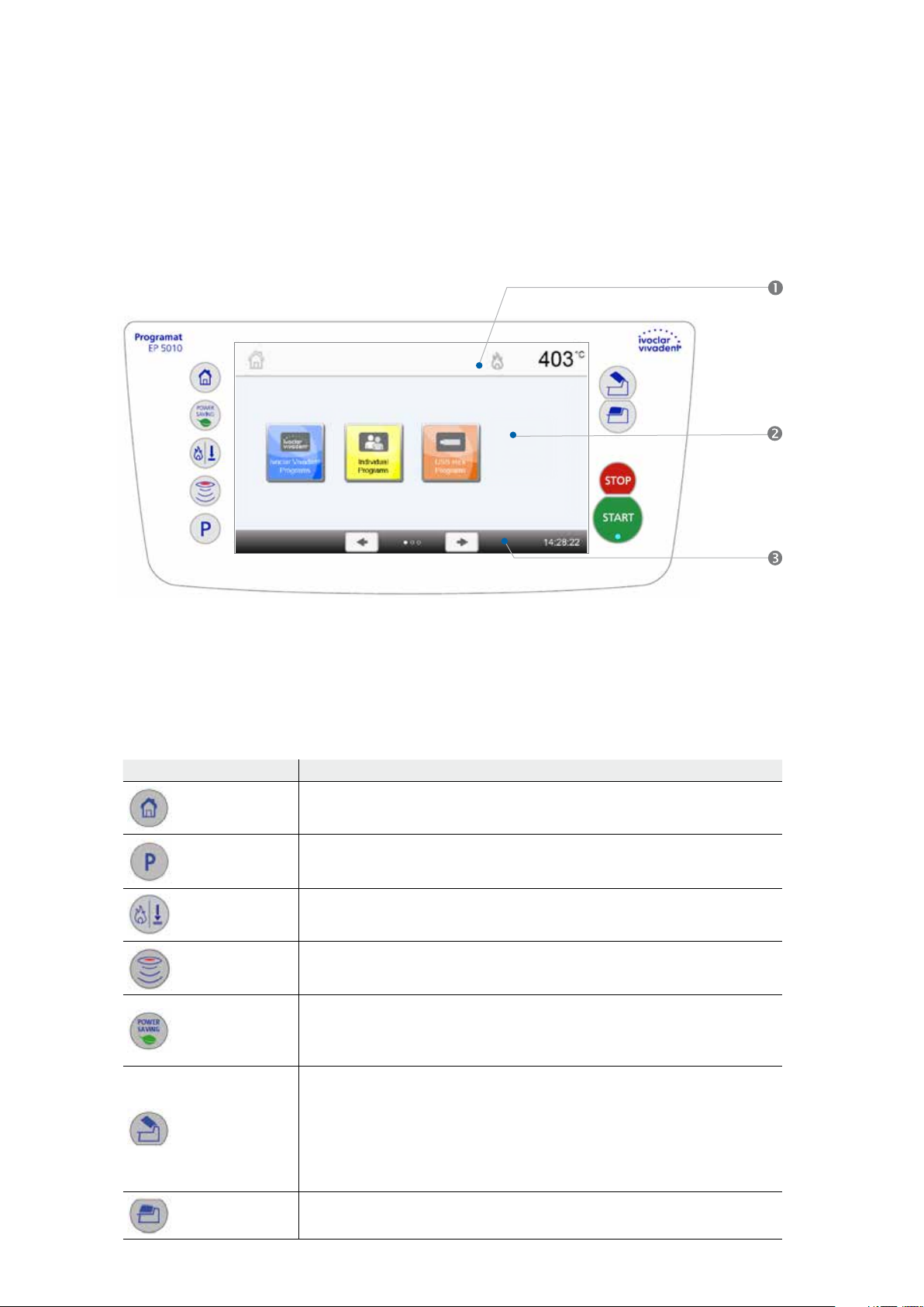
The Programat EP 5010 is equipped with a wide-screen colour display. The furnace can be intuitively operated by means of
the membrane-sealed keypad and the touch screen. The touch buttons can be actuated by slightly tapping the display with
the fingertip and the furnace runs the desired function.
The user interface in the display is divided into three sections:
1. Information bar (e.g. indication of the current furnace temperature, selected program type, etc.)
2. Main screen (e.g. editing firing programs, changing the settings, etc.)
3. Navigation bar (e.g. scrolling, scrolling to higher levels, opening favourite programs, etc.)
5.1.2 Explanation of the key functions
Key Function
HOME key
Switch to home screen (main menu).
PROGRAM key
Press once: Display of the currently selected program.
Press twice: Switch to the program selection via number entry.
CHANGE OPERATING MODE key
By pressing this key, you can switch between the firing and the press mode.
IRT key
With this key, the infrared image of the object can be displayed during the closing
process.
POWER SAVING key
By pressing this key, the power-saving function is activated (only possible with the furnace
head closed and the furnace on idle). The display shows the power-saving icon. Pressing
any key ends the automatically activated power-saving function.
OPEN FURNACE HEAD key
Quick cooling with the furnace head open:
If the furnace head is completely open and the OPEN FURNACE HEAD key is pressed
again, the quick cooling function is activated. I.e. the vacuum pump is switched on for
5 minutes. This function can be stopped at any time by pressing the STOP, CLOSE
FURNACE HEAD or START key. This function can be activated any time when the furnace
head is open.
CLOSE FURNACE HEAD key
23
Page 24
5. Operation and Configuration
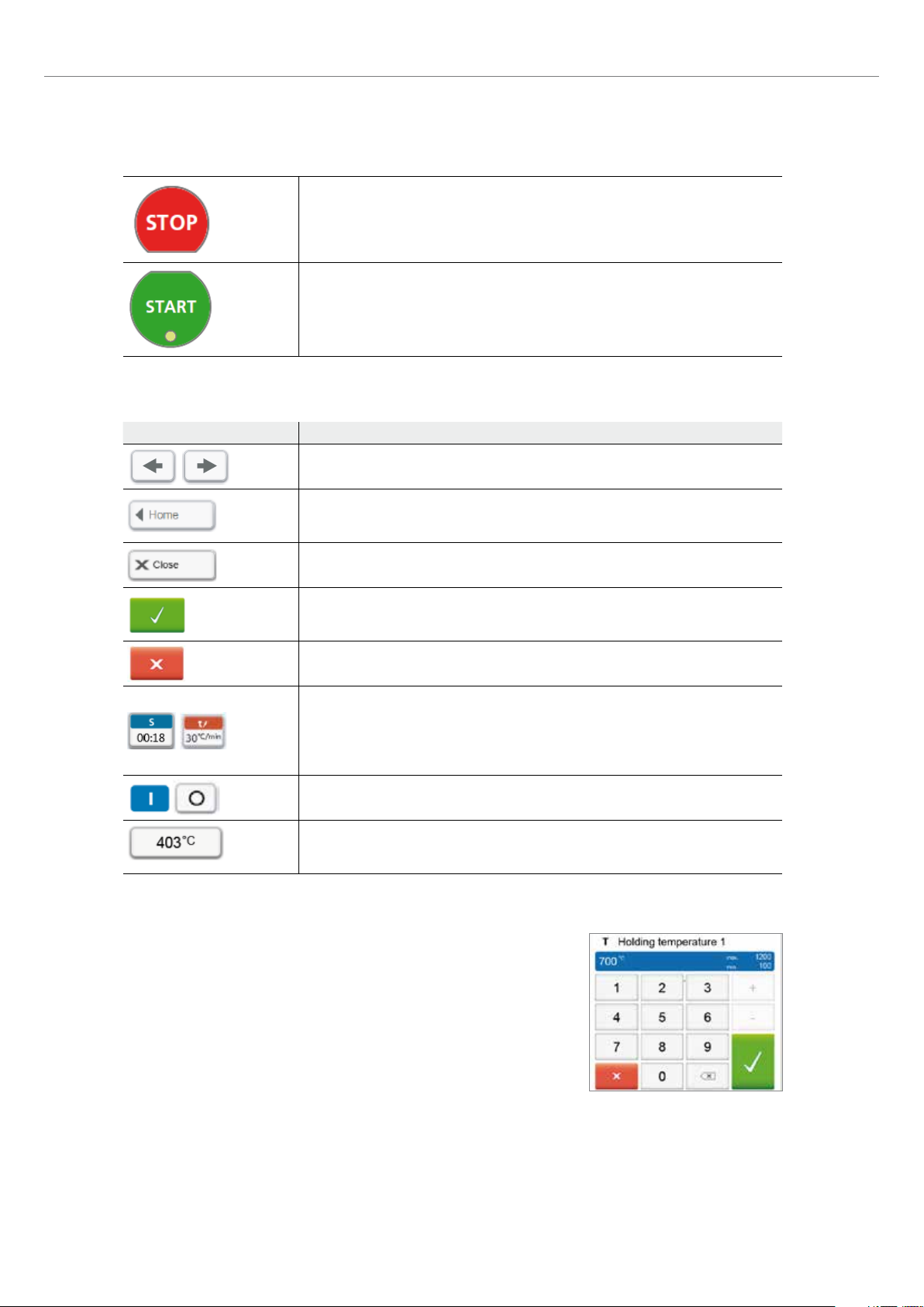
STOP key
A program in progress can be paused by pressing the STOP key and stopped by pressing
STOP twice. Movement of the furnace head can be stopped at any time by pressing
STOP. Acoustic signals can be confirmed by pressing the STOP key.
START key (Start LED)
Starts the selected program. The green LED indicates that a program is active. If the
program is paused (1x STOP), the Start LED flashes until renewed pressing of START
results in the program being resumed.
5.1.3 Explanation of the most important touch buttons
Button Function
Scroll left / Scroll right
With these buttons, you can e.g. scroll to page 2 of the home screen.
Back with note
With this button, you can change to the "next higher" menu level. The button indicates
to which screen you change, e.g. to the home screen.
Close
With this button, you can leave sub-menus.
Confirm entry
This button is used to confirm an entry. If the button appears pale green, no entry has
been made yet or the value entered is not in the acceptable range.
Cancel entry
This button is used to cancel an entry. Changed values are not saved.
Program parameters
Pressing these buttons allows you to change program parameters. A selection list or
numeric pad for entering the values appears.
The upper half of the button itself shows the parameter in question (e.g. closing time),
while the lower half shows the entered value (e.g. 00:18).
On / Off button
This button is used to switch functions on or off.
Parameters
By pressing these buttons, a selection list or numeric pad for entering the values
appears.
24
5.1.4 Explanation of the numeric pad and selection list
– Numeric pad
The numeric pad enables the entering and changing of parameters, e.g. in firing
programs or setting menus. Additionally, the currently set value as well as the
minimum and maximum values are indicated.
An entry must be confirmed with the green button. As soon as the entry has
been confirmed, the numeric pad is closed. If the button appears pale green, the
value is not in the acceptable range.
The numeric pad can be closed with the red button, without any parameters
being changed.
Page 25
5. Operation and Configuration
– Selection list
In the selection list, the desired parameter can be selected by using the up / down
arrows. An entry must be confirmed with the green button. After that, the selection
list is closed.
The selection list can be closed with the red button, without any parameters being
changed.
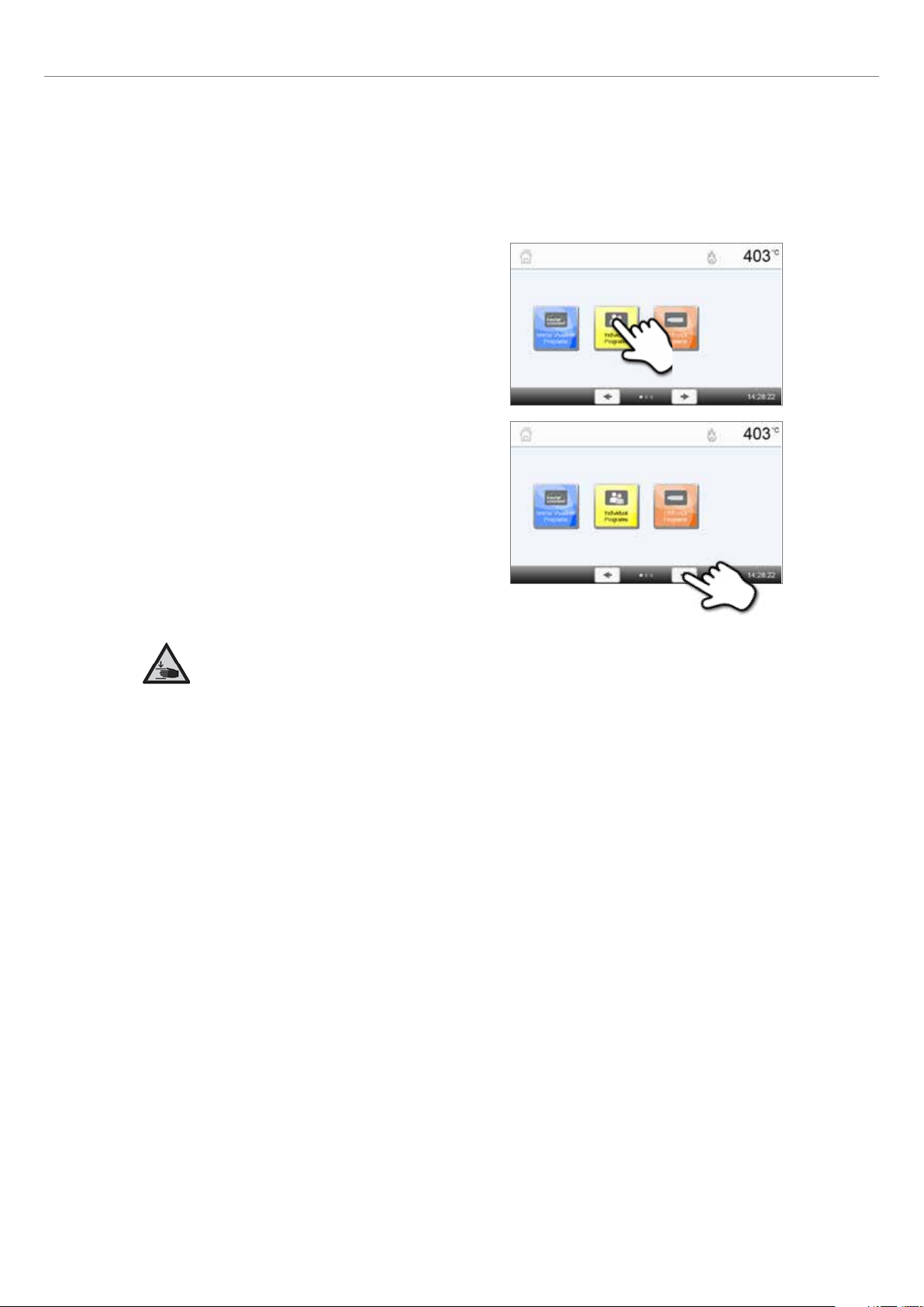
5.1.5 Selecting the operating mode
The furnace can be operated in two different modes:
– Pressing:
Only press programs can be selected. The stand-by temperature of the furnace is set to 700 °C.
– Firing:
Only firing programs can be selected. For Ivoclar Vivadent programs, the stand-by temperature of the furnace is set to
403 °C.
In order to switch between the press and the firing modes, you must press the CHANGE OPERATING MODE key to change
the operating mode (Chapter 5.1.2).
Once the CHANGE OPERATING MODE key has been pressed, the operating mode can be selected.
1. Select the desired operating mode.
2. After the operating mode is selected, a note is displayed indicating
the different stand-by temperatures of the respective operating modes.
Switching from "Firing" to "Pressing": Make sure that the furnace
has heated up to 700 °C before starting the press program.
Switching from "Pressing" to "Firing": Make sure that the furnace
has cooled down to 403 °C before starting the firing program.
In the information bar, the operating mode is displayed in addition to the temperature.
Icon Meaning
Operating mode "Pressing"
If this icon is displayed in the information bar, the operating mode "Pressing" is active.
In this operating mode, only press programs are available and the stand-by temperature
is set to 700 °C.
Operating mode "Firing"
If this icon is displayed in the information bar, the operating mode "Firing" is active. In
this operating mode, only firing programs are available and the stand-by temperature is
set to 403 °C.
25
Page 26
5. Operation and Configuration
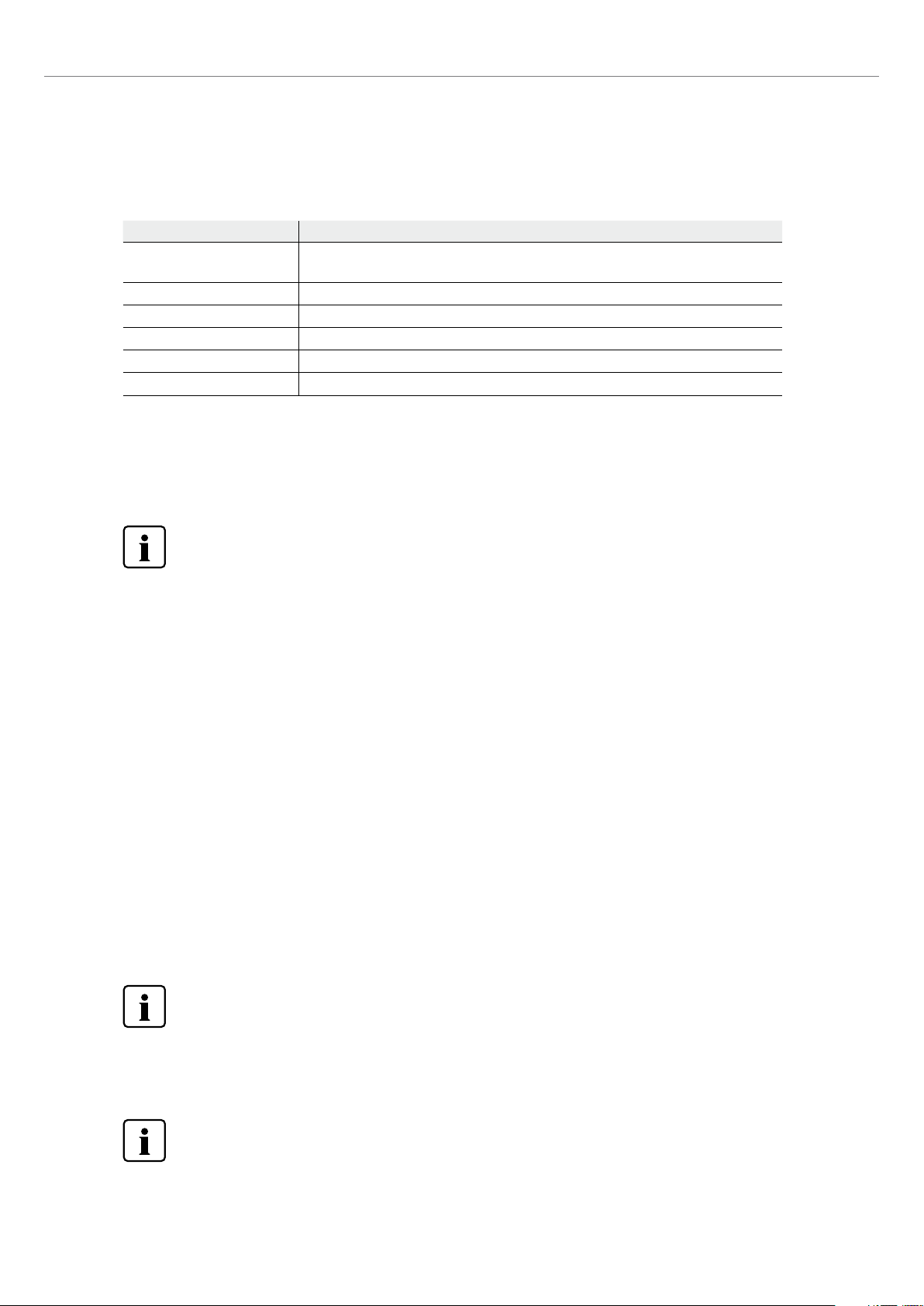
5.1.6 Explanation of the home screen
After the furnace is switched on, the display shows the home screen. All functions of the Programat can be selected from
this screen. You can switch back to the home screen with the HOME key.
By pressing a selection button, you will reach the corresponding menu
(e.g. firing programs, settings, calibration, etc.).
By pressing the [Arrow] buttons, the next page of the home screen is
accessed, where additional functions are available.
The circles between the arrows indicate the number of pages.
The current page is marked with a light dot.
5.1.7 Explanation of the speaker signals
– Upon closing the furnace head below 100 °C
– Upon completion of the self-test
To inform the user that the automatic self-test has been successfully completed, a pre-set, not modifiable melody is
played.
– Furnace head open and temperature below 560 °C
To inform the user that the temperature in the open furnace head has dropped below 560 °C the selected melody is
played (5 seconds). Thus, the furnace head has sufficiently cooled down for the next program start. The acoustic signal
can be stopped by pressing the STOP key.
– Furnace head open and temperature below 360 °C
To inform the user that the temperature in the open furnace head has dropped below 360 °C, the selected melody is
played. If the first playback (10 seconds) is not acknowledged with the STOP key, a second playback sounds after
5 minutes (for 5 minutes) to signal that the furnace head is cooling down. After that, no further signal is played.
If one of the two playbacks is acknowledged with the STOP key, the signal transmitter is switched off and no further
signals will be sounded.
– For error messages
Error messages are acoustically supported with the 'error melody' (endless beep). The acoustic signal can be confirmed
by pressing the STOP key, while the error message still remains visible. If the error message is acknowledged with the
corresponding button, the signal transmitter is also switched off.
– For active press cycle
To inform the user that the press cycle has been started, a pre-set, not modifiable melody is played.
There is a risk of crushing when closing the furnace head. If the furnace head is closed below 100 °C, the user
is alerted to the hazard by an acoustic signal.
26
– Upon completion of the press program
To inform the user that the press program has been completed, the selected melody is played continuously.
Page 27
5. Operation and Configuration
5.1.8 Optical status and progress display (OSD)
The Optical Status Display (12a) shows the most important statuses of the furnace. The following activities are shown:
Colour Activity
Yellow
Yellow (flashing) Information, notification or error message
Green The furnace is ready for use; the currently selected program can be started.
Orange Program is closing the furnace head or is in predrying mode.
Red Program is heating up or is in holding time mode.
Blue Program is in long-term cooling or is opening the furnace head.
Progress display:
During an active process, the progress of the program is also shown by the OSD. This is done by stage-to-stage lighting up
of the lateral OSD (12b).
5.1.9 User code
For safety reasons, a user code is required for certain settings. The user code ex factory is as follows:
The furnace is performing a self-test or is not ready for use, as the recommended
temperature range for a program start has not yet been reached.
1234
The user code can be individually changed. See Chapter 5.4 Settings for details.
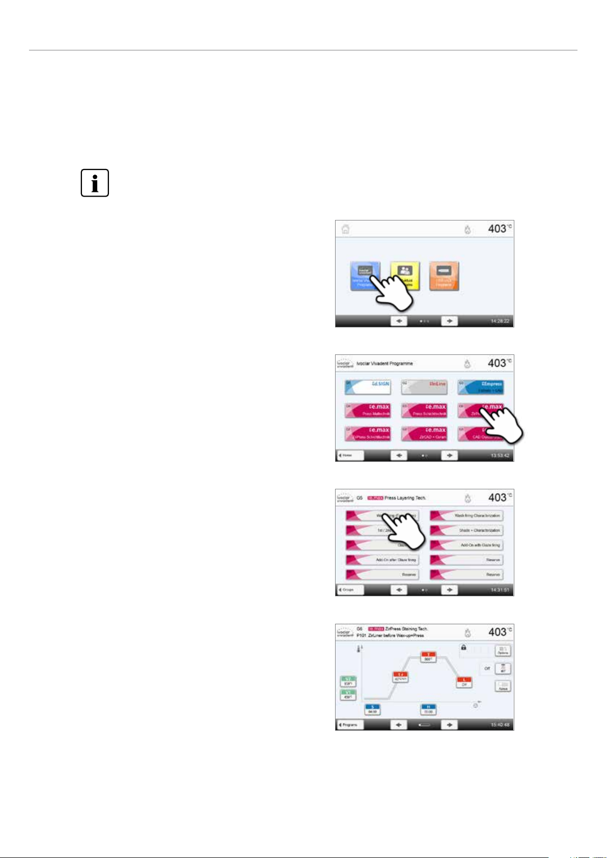
5.2 Firing programs and programming options
5.2.1 Program structure
The furnace offers several types of programs:
a. programs for Ivoclar Vivadent materials
b. 500 free, individually adjustable programs
c. 500 free, individually adjustable programs on a USB stick.
The program types are subdivided into program groups. Each program group consists of 20 programs. All programs are
equivalent and therefore full-fledged programs. All the parameters can be individually set in each program.
a) Programs for Ivoclar Vivadent materials (see enclosed Program Table)
When the furnace is delivered ex factory, the Ivoclar Vivadent programs already contain the recommended material parameter settings and are write-protected. Consequently, it is not possible to accidentally overwrite these programs.
If required, the parameters can be changed and overwritten at any time, if the programs are to be used for other purposes.
Therefore, these programs are also available as individual programs.
In case of software updates, individually changed parameters in Ivoclar Vivadent programs might be reset to the
factory settings or changed!
b) 500 free, individually adjustable programs
The programs are designed in such a way that they can be either used as conventional, one-stage programs or as twostage programs, if required. The programs and program groups can be individually named.
In case of software updates, individually changed parameters in free programs are NOT reset to the factory
settings or changed!
27
Page 28
5. Operation and Configuration
c) 500 free, individually adjustable programs on a USB stick
In a first step, a USB stick must be prepared as program memory (see Chapter 5.4). The programs are designed in such a
way that they can be either used as conventional, one-stage programs or as two-stage programs, if required. The programs
and program groups can be individually named.
In case of software updates, individually changed parameters in free programs are NOT reset to the factory
settings or changed!
5.2.2 Program selection
The program selection requires only few steps:
1. Select the program type.
2. Select the program group.
3. Select the program.
4. Start the program or edit the program parameters.
The firing program can now be started or, as an alternative, the
program parameters can be changed.
28
Quick program selection
Pressing the P key switches to the program screen of the current program. When the program screen is shown, pressing
the P key again switches to the quick program selection by means of number entry.
Page 29

5. Operation and Configuration
Browsing the programs
If a program has been selected, the neighbouring programs can be
accessed by pressing the [Arrow] buttons.
5.2.3 Program screen / Editing programs
If a program has been selected, the program screen is displayed. The firing programs can be changed or edited in this
screen.
For Ivoclar Vivadent programs, the write-protection must be deactivated first before any parameters can be
changed.
The following information is displayed:
1. Information bar
– Program designation
– Current furnace temperature
2. Firing curve
– Closing time, holding time
– Temperature increase rate, holding temperature,
long-term cooling
– Vacuum on, vacuum off
3. Program options
In addition to the parameters shown in the firing curve,
several other options are available that can be activated by
pressing the [Options] button. The icons in the grid show the activated options.
4. IRT options
Different operating modes are available for the Programat Infrared Technology. These modes can be selected by pressing
the [IRT] button. The icon in the grid shows the activated IRT operating mode.
Editing parameters
Parameters are entered or edited in two steps.
Example: Setting the holding temperature
1. Press the [T] button.
2. Enter the desired holding temperature and confirm by
pressing the green button.
The holding temperature was successfully changed. All the other
parameters shown in the firing curve can be changed / edited in the
same way.
29
Page 30

5. Operation and Configuration
Changing program options
Pressing the [Options] button opens the menu for advanced program options.
Example 1: Deactivating the write-protection
1. Press the [Options] button.
2. Press the [Deactivate Write-Protection] button.
3. Press the [Close] button to leave the Options menu.
4. The write-protection was successfully deactivated.
The lock symbol is no longer shown in the display next to the
[Options] button.
30
Page 31

5. Operation and Configuration
Example 2: Changing the predrying temperature
1. Press the [Options] button.
2. Press the [Predrying Temperature] button.
3. Enter the desired predrying temperature and confirm by
pressing the green button.
4. The predrying temperature was successfully changed.
Press the [Close] button to leave the Options menu.
The program screen now shows the symbol "Predrying active" next
to the [Options] button.
31
Page 32

5. Operation and Configuration
Selecting the IRT operating mode
By pressing the [IRT] button, the menu for selecting the IRT operating mode is opened.
1. Press the [IRT] button.
2. Select the desired IRT operating mode.
The menu is automatically closed once the desired operating mode
has been selected. The selected IRT mode is displayed in the program
display next to the [IRT] button.
32
Page 33

5. Operation and Configuration
Two-stage programs
A two-stage program permits firing procedures on two temperature levels with different parameters (e.g. Holding time
Stage 1, Holding time Stage 2) to be conducted.
The function "Two-stage program" can be selected in the Options menu.
The program screen now shows the "Two-stage program" symbol
next to the [Options] button and the firing curve for the parameter
entry is indicated in two stages.
Automatic plausibility check of the parameters
The furnace is equipped with an automatic plausibility check function. The parameters are checked upon each program
start. In case of contradictory parameter combinations, the program stops automatically and the respective information is
indicated.
33
Page 34

5. Operation and Configuration
5.2.4 Adjustable parameters in the program screen
S – Closing time
The closing time controls the duration of the furnace head closing process.
Value range: 00:18 – 30:00 (mm:ss)
t – Temperature increase rate (for two-stage programs: t1)
The temperature increase rate defines by how many degrees per minute the furnace heats up.
Value range °C: 10 – 140 °C/min; Value range °F: 18 – 252 °F/min
T – Holding temperature (for two-stage programs: T1)
The holding temperature defines the temperature at which a firing process is conducted.
Value range °C: 100 – 1200 °C; Value range °F: 212 – 2192 °F
H – Holding time (for two-stage programs: H1)
The holding time indicates how long an object is fired at the holding temperature.
Value range: 00:00 – 60:00 (mm:ss)
Vacuum on (for two-stage programs: V11)
The parameter defines the temperature at which the vacuum is activated.
Value range °C: Off or 1 – 1200 °C; Value range °F: 0 or 34 – 2192 °F
Vacuum off (for two-stage programs: V21)
The parameter defines the temperature at which the vacuum is deactivated.
• Holding time without vacuum: If V2 is set one degree lower than the holding temperature, the vacuum is
ended before the holding time.
• Holding time with vacuum: If V2 corresponds to the holding temperature, the vacuum is maintained
during the entire holding time.
• Long-term cooling with vacuum: If V2 is set one degree higher than the holding temperature, the
vacuum is maintained during long-term cooling.
Value range °C: Off or 1 – 1200 °C; Value range °F: 0 or 34 – 2192 °F
Long-term cooling
If long-term cooling is activated, the furnace cools to the set temperature (L) at the end of the holding
time with the furnace head closed.
Value range °C: Off or 50 – 1200 °C; Value range °F: 0 or 122 – 2192 °F
Cooling rate
Can only be set if long-term cooling "L" is activated. This parameter defines by how many degrees per
minute the furnace cools down.
Value range °C: Off or 1 – 50 °C/min; Value range °F: Off or 2 – 90 °F/min
t2 – Temperature increase rate Stage 2
This parameter defines for the second temperature level by how many degrees per minute the furnace
heats up.
Value range °C: 10 – 140 °C/min; Value range °F: 18 – 252 °F/min
T2 – Holding temperature Stage 2
The holding temperature for the second temperature level defines the temperature at which a firing
process is conducted.
Value range °C: 100 – 1200 °C; Value range °F: 212 – 2192 °F
H2 – Holding time Stage 2
The holding time for the second temperature level indicates how long an object is fired at the holding
temperature.
Value range: 00:00 – 60:00 (mm:ss)
Vacuum on Stage 2
This parameter defines the temperature at which the vacuum for the second temperature level is activated.
Value range °C: Off or 1 – 1200 °C; Value range °F: 0 or 34 – 2192 °F
Vacuum off Stage 2
This parameter defines the temperature at which the vacuum for the second temperature level is
deactivated. If V2
holding time.
Value range °C: Off or 1 – 1200 °C; Value range °F: 0 or 34 – 2192 °F
corresponds to the holding temperature, the vacuum is maintained during the entire
2
34
Page 35

5. Operation and Configuration
5.2.5 Adjustable parameters in the Options menu
In addition to the parameters shown in the firing curve, several other options are available that can be activated by pressing
the [Options] button (see Chapter 5.2.3). Active options are displayed as icons in the grid next to the [Options] button.
The following firing program options are available:
Night program
If this function is active, the furnace head remains open after the firing process, the heater is switched off
and the green Start LED flashes. No acoustic signals are sounded. Once the temperature drops below
100 °C, the furnace head closes, the heater remains switched off and the furnace cools down to room
temperature.
Advantages of the night function:
After a power failure, the night program is always resumed. The program is resumed at the position, at
which the power failure occurred. After a longer power failure, the furnace head does not heat up to
stand-by temperature and the object is protected at room temperature with the furnace head closed.
If the night program function is switched on, it is active only for the next program cycle.
Setting options: On / Off
Program write-protection
If the program write-protection is activated, the program parameters and program options cannot be
changed. This is to prevent accidental changes to the program.
B
Setting options: On / Off
Stand-by temperature
The stand-by temperature is the temperature to which the furnace heats up immediately after switching
on. The temperature is maintained with the furnace head closed and when no firing process is active.
Programat furnaces are programmed to a stand-by temperature of 403 °C in the factory. The temperature
can be individually set for each program.
Value range °C: 100 – 700 °C; Value range °F: 212 – 1292 °F
Two-stage program
If this function is activated, the selected program can be programmed on two temperature levels.
Setting options: On / Off
IRT mode (only available if Infrared Technology "ON")
If the IRT system is active, three different IRT modes can be selected:
– Standard: suitable for all conventional firing cycles (e.g. layering, opaquer, wash, gloss, glaze,
characterization firing, etc.) with the Programat firing tray
– Crystallization: exclusively suitable for crystallization firing cycles (e.g. IPS e.max CAD crystallization) with
the IPS e.max CAD Crystallization Tray
– Fusion: exclusively suitable for fusion firing cycles (e.g. IPS e.max CAD fusion / crystallization CAD-on)
with the IPS e.max CAD Crystallization Tray
If IRT is activated, the mode "Standard" is used as the default setting.
Setting options: Standard, crystallization, fusion
Predrying temperature Stage 1 (only available if Infrared Technology "OFF")
In a program with activated predrying in Stage 1, the desired "predrying temperature" is reached (heating
or cooling) after the start with the furnace head open. Once this temperature is reached, predrying is
conducted during the "predrying holding time". Once this time has elapsed, the furnace closes within the
desired closing time.
The predrying temperature for Stage 1 can be set as follows:
Value range °C: OFF or 100 – 700 °C; Value range °F: OFF or 212 – 1292 °F
Predrying holding time Stage 1 (only available if Infrared Technology "OFF")
This parameter defines the duration of the predrying process for Stage 1 once the desired predrying
temperature has been reached.
Value range OFF or 00:00 – 60:00 (mm:ss)
35
Page 36

5. Operation and Configuration
Predrying temperature Stage 2 (only available if Infrared Technology "OFF")
Predrying for Stage 2 is only available if Stage 1 has also been activated. The parameters are set in the
same way. At this stage, the furnace head is half open.
Value range °C: OFF or 100 – 700 °C; Value range °F: OFF or 212 1292 °F
Predrying holding time Stage 2 (only available if Infrared Technology "OFF")
This parameter defines the duration of the predrying process for Stage 2 once the desired predrying
temperature has been reached.
Value range OFF or 00:00 – 60:00 (mm:ss)
Thermo Shock Protection (TSP) (only available if Infrared Technology "OFF")
The TSP function protects the dental-lab work during the closing process. For this purpose, the TSP function
gauges the temperature of the firing chamber in the furnace head upon the start of the firing program. If
required, the closing path within the set closing time S is adjusted.
Setting options: On / Off
Pre-vacuum
If a firing program with pre-vacuum is conducted, the vacuum pump is switched on at the end of the
closing time (as soon as the furnace head is closed) and runs until the pre-vacuum time has elapsed. The
heating phase begins after the pre-vacuum time is over.
Hv
The value V1 is ignored upon the start of a program with individually activated pre-vacuum. The vacuum is
maintained until V2 is reached. V2 must be higher than the stand-by temperature B.
Setting options: OFF or 01:00 – 05:00 (mm:ss)
Vacuum holding time
With this function, the vacuum share of the holding time can be individually set.
Example: H (Holding time) = 02:00 (mm:ss). If a vacuum share of 50% is desired, the parameter "Vacuum
holding time (Hv)" has to be set to 01:00 (mm:ss).
Setting options: OFF or 00:01 – 60:00 (mm:ss)
Quick opening of the furnace head
If the option "Quick opening of the furnace head" is activated, the furnace head opens at maximum
speed at the end of the holding time.
Setting options: On / Off
Extraction system
If this function is activated, any vapours are extracted during the closing process by means of the vacuum
pump, and fresh air is sucked in for a better firing and drying result.
Setting options: On / Off
36
Page 37

5. Operation and Configuration
5.6 Adjustable parameters in the IRT menu
If the infrared technology is activated, the temperature is measured directly on the surface of the object during the predrying
or closing process. The furnace regulates the closing and predrying process based on the data measured by the infrared
camera.
Homogeneous drying and heating of the object is ensured by the heating of the heating muffle and the furnace head
movements (furnace head opens and closes depending on the situation).
Different operating modes are available for the IRT function. These modes can be selected by pressing the [IRT] button:
IRT
The IRT operating mode is the preferred and recommended operating mode for standard veneer and allceramic firing processes.
If the IRT operating mode is selected, the infrared camera controls the predrying and closing process in
such a way that the processes are performed very quickly and efficiently. The time saving compared to
conventional predrying and closing processes amounts up to 20%.
IRT Plus
If the IRT Plus operating mode is selected, the infrared camera controls the predrying and closing process
with a reduced drying rate. As a result, predrying and closing takes longer.
The IRT Plus operating mode is recommended for opaquer firing cycles and large restorations.
IRT Off
If the IRT Off mode is selected, the infrared camera is deactivated. Predrying and closing processes are
performed as usual, e.g. by manually entering the closing time.
37
Page 38

5. Operation and Configuration
5.2.7 Starting and stopping programs / the operating indicator
Once the program is started by pressing START, the firing curve display appears.
The following information is displayed:
– Information bar
The program name and the current furnace temperature are shown in the information bar in the upper margin of the
display.
– Main area
The vacuum is shown on the left side of the main screen. The progress of the program is shown in the form of a firing
curve. The estimated remaining time is also displayed in 10-second intervals. If no vacuum is activated, the vacuum
indicator and all the corresponding parameters are blank.
The process status is displayed in colour in the firing curve:
– Orange: Program is closing the furnace head or is in predrying mode.
– Red: Program is heating up or is in holding time mode.
– Blue: Program is in long-term cooling or is opening the furnace head.
Active firing program options are shown in the grid next to the [Options] button.
If a two-stage program is selected, the firing curve is shown in two stages.
38
Page 39

5. Operation and Configuration
Changing the operating indicator
The active firing program can be displayed in two ways:
– operating indicator "firing curve"
– operating indicator "remaining time".
If the [Display] button is pressed during an active program, the operating indicator can be switched.
If the [Display] button is pressed while the firing curve is displayed, the remaining time will be shown. The remaining time
indicator informs the user about the time that is left until the process is completed. The remaining time is displayed in the
centre of the screen in large characters and is thus visible even from a distance.
The factory settings of the furnace are such that the firing curve is automatically displayed upon the start of a program.
39
Page 40

5. Operation and Configuration
5.2.8 Pausing the active program
– Press STOP once to pause a running program (green LED flashing). Press the STOP key twice to completely stop the
program or press START to continue.
– If the program is paused, the display shows a flashing "Pause" and the indicator changes back to the program screen.
– If a program is stopped prematurely, "Vacuum release" is shown in the display during the flooding of the firing
chamber.
5.2.9 Changing the parameters while the program is running
Most program parameters, which have not yet been executed, can be changed while the program is paused. Change the
parameters as described in Chapter 5.2.3.
5.2.10 Managing programs
Press the [Admin] button in the program view to open the Admin
menu.
The following functions are available:
– copy program
– reset program to factory settings
– select product brand
– rename group
– rename program.
40
Page 41

5. Operation and Configuration
5.2.11 Copying programs
With the copy wizard, individual programs, program groups and program sectors can be copied. The source and target of
the copy process can be selected in the copy assistant.
Programs and program groups cannot be copied into the sector for Ivoclar Vivadent programs. This sector is
protected and reserved for original Ivoclar Vivadent programs.
1. Press the corresponding [Execute] button in the Admin
menu.
2. Select the objects to be copied.
(program sector, program group or individual program)
3. Make a selection depending on the desired copy content.
(program sector, program group, or individual program)
4. Select a target.
Confirm the selection with the green button or close the copy wizard
with the red button.
5. The copy process can be continued with the green button.
The red button is used to abort the copy process.
41
Page 42

5. Operation and Configuration
5.2.12 Resetting the program to factory settings
This function is used to reset a changed program to factory settings.
1. Press the corresponding [Execute] button in the Admin
menu.
2. Enter the user code to confirm that the program is to be
reset to factory settings.
3. The program has been successfully reset to factory settings.
5.2.13 Selecting the product brand
The product brand for the current group can be selected.
1. Press the corresponding [Execute] button in the Admin
menu.
42
2. Select the desired product brand. Confirm the entry with
the green button.
Page 43

5.2.14 Renaming the program or program group
The current program and current program group can be renamed
(only possible for individual programs).
1. Press the corresponding button in the Admin menu and
select whether the program or the group should be
renamed.
2. Enter the desired program or group name. Confirm the
entry with the green button.
5. Operation and Configuration
43
Page 44

5. Operation and Configuration
5.3 Press programs and programming options
The furnace offers different press program ranges:
a. press programs for Ivoclar Vivadent materials
b. 20 free, individually adjustable press programs.
a) Press programs for Ivoclar Vivadent materials
When the furnace is delivered ex factory, the Ivoclar Vivadent programs already contain the recommended material
para meters. They cannot be deleted or overwritten. The parameters are not shown in the software.
b) Free, individually adjustable press programs
Individual press programs can be freely programmed and renamed.
In case of software updates, individually changed parameters in free programs are NOT reset to the factory
settings or changed!
5.3.1 Program selection in the "Pressing" mode and with activated IRT investment ring analysis
The program selection requires only a few steps:
1. Select the program type.
2. Select the program.
3. Load the furnace.
You can now load the firing chamber with the hot investment ring.
The IRT investment ring analysis starts immediately after loading of
the furnace:
– automatic identification of the investment ring size
– check of the investment ring preheating temperature.
44
For details regarding the IRT investment ring analysis see
Chapter 5.4.
4. Start or edit the press program.
Now, the press program can be started. Individual press programs
can be edited.
Page 45

5. Operation and Configuration
5. Results panel
The following information is displayed at the end of the press
program:
– press time (mm:ss)
– press distance (mm)
– investment ring analysis (see Chapter 5.4.1 for details).
By pressing the [Confirmation] button, the results panel is closed
and the program selection is displayed.
5.3.2 Program selection in the "Pressing" mode and with deactivated IRT investment ring analysis
The program selection requires only a few steps:
1. Select the program type.
2. Select the program.
3. Select the investment ring size.
Depending on the program selected, different investment ring sizes
can be chosen:
– 100-gram investment rings
– 200-gram investment rings
– 300-gram investment rings.
4. Start or edit the press program.
Now, the press program can be started.
Ivoclar Vivadent press programs cannot be changed or edited.
Individual press programs can be edited (see Chapter 5.3.4.).
45
Page 46

5. Operation and Configuration
5. Results panel
The following information is displayed at the end of the press
program:
– press time (mm:ss)
– press distance (mm).
By pressing the [Confirmation] button, the results panel is closed and
the program selection is displayed.
5.3.3 Starting and stopping press programs / the operating indicator
Once the press program has been started by pressing the Start key,
the operating indicator is shown.
The following information is displayed:
Information bar:
The current furnace temperature and the program area are shown in
the information bar in the upper margin of the display.
Main area:
The following information is displayed in the main area:
– selected program and investment ring size
– vacuum display
– remaining time and progress bar
– animation (preheating, holding, pressing).
5.3.4 Editing individual press programs
For the all-ceramic systems from Ivoclar Vivadent (e.g. IPS e.max, IPS Empress Esthetic), only the original Ivoclar
Vivadent press programs must be used as they are especially coordinated with the respective materials.
After the individual press program was selected, the following information is displayed on the program screen:
1. Information bar:
– Program name, investment ring size
– Current furnace temperature
2. Firing curve:
– Holding time
– Temperature increase rate, holding temperature
– Stop speed
3. Program options
In addition to the parameters shown in the firing curve,
several other options are available that can be activated by
pressing the [Options] button. The icons in the grid show
the activated options.
46
Page 47

Editing parameters
Parameters are entered or edited in two steps.
Example: Setting the holding temperature
1. Press the [T] button.
2. Enter the desired holding temperature and confirm by
pressing the green button.
5. Operation and Configuration
The holding temperature was successfully changed. All the other parameters shown in the firing curve can be changed /
edited in the same way.
Changing the program options
Pressing the [Options] button opens the menu for advanced program options.
Example 1: Activating the write-protection
1. Press the [Options] button.
2. Press the [Activate Write-Protection] button.
3. Press the [Back] button to leave the Options menu.
47
Page 48

5. Operation and Configuration
4. The write-protection was successfully activated. The lock
symbol is shown next to the [Options] button in the display.
5.3.5 Adjustable parameters in the program screen
t – Temperature increase rate
The temperature increase rate defines by how many degrees per minute the furnace heats up.
Value range °C: 10 – 140 °C/min; Value range °F: 18 – 252 °F/min
T – Holding temperature
The holding temperature defines the temperature at which the press process is started.
Value range °C: 100 – 1200 °C; Value range °F: 212 – 2192 °F
H – Holding time
The press process starts once the holding time ends.
Value range: 00:00 – 60:00 (mm:ss)
E – Stop speed
This parameter defines the end of the press process.
For the layering technique, Ivoclar Vivadent recommends a stop speed of 300 µm/min; for the staining
technique a stop speed of 150 µm/min.
– Higher values (stop speed of e.g. 300 µm/min) result in the press cycle being stopped sooner.
– Lower values (stop speed of e.g. 100 µm/min) result in the press cycle being stopped later. Consequently,
the press cycle is prolonged.
Value range: 0 – 10,000 (µm/min)
5.3.6 Adjustable parameters in the Options menu
In addition to the parameters shown in the firing curve, several other options are available that can be activated by
pressing the [Options] button. Active options are displayed as icons in the grid next to the [Options] button.
The following press program options are available:
Program write-protection
If the program write-protection is activated, the program parameters and program options cannot be
changed. This is to prevent accidental changes to the program.
Setting options: On / Off
B
Stand-by temperature
The stand-by temperature is the temperature to which the furnace heats up immediately after switching
on. The temperature is maintained with the furnace head closed and when no firing or press process is
activated.
In the "Pressing" mode, Programat furnaces feature an automatic stand-by temperature of 700 °C as the
factory setting. The temperature can be individually set for each program.
48
Value range °C: 100 – 700 °C; Value range °F: 212 – 1292 °F
Page 49

5. Operation and Configuration
5.4 Advanced functions of the furnace
5.4.1 Settings
To reach the Settings menu, scroll to page 2 in the home screen and press the [Settings] button.
Example: Changing the brightness of the display
1. Open the Settings menu.
Scroll to page 2 in the home screen and press the [Settings] button.
2. Open the display brightness setting.
The [Arrow] buttons are used to scroll through the Settings menu.
Press the button until the setting "Display brightness" appears in the
display.
3. Change the brightness of the display.
Press the touch button in the line "Display brightness".
4. Select the desired display brightness.
Select the desired display brightness in percent and confirm the entry
with the green button or cancel the entry with the red button.
The setting was changed.
To return to the home screen, press either the [Home] touch button in the navigation bar or the HOME key on
the membrane-sealed keypad.
49
Page 50

5. Operation and Configuration
The following parameters can be changed in the Settings menu:
Temperature unit
Choose between °C and °F.
Setting options: °C / °F
Vacuum unit
Choose between mbar and hPa.
Setting options: mbar and hPa
Vacuum quality
Set the final vacuum value. This value defines the negative pressure in the furnace head at which the
furnace has reached a vacuum quality of 100%.
Setting options: 0 – 200 mbar
Language
Select the desired operating language.
Setting options: German, English, Italian, French, Spanish, Portuguese, Swedish, Dutch, Turkish, Russian,
Polish, Croatian, Traditional Chinese, Mandarin Chinese, Finnish, Norwegian, Slovenian, Czech, Slovakian,
Hungarian, Hindi, Japanese, Korean, Arabic, Farsi
Volume
Select the desired volume of the acoustic signals.
Setting options: Off / 20 – 100% in 10%-steps
Melody
Select the desired melody for the acoustic signals.
Setting options: Melody 1 to 20
Time
Set the current time.
Setting options: hh:mm:ss
Date
Set the current date.
Setting options: according to the set date format
Date format
Set the date format.
Setting options: dd:mm:yyyy; mm:dd:yyyy
Automatic power-saving mode
If the power-saving mode is activated and the furnace head closed, this function is automatically started
after 30 minutes, provided the furnace is in idle mode and no key is pressed during that time.
The display shows the power-saving icon. Pressing any key ends the automatically activated power-saving
function. The power-saving mode is not available in the press operating mode.
Setting options: On / Off
Optical Status Display (OSD)
The OSD can be switched on or off.
Setting options: Off / On 10 – 100% in 10%-steps
Display brightness
Set the display brightness.
Setting options: 20 – 100% in 10%-steps
User code
The user code can be individually changed.
It is recommended to make a note of the individually changed user code and to keep it
separately. If forgotten, the user code may only be reset with the help of the After Sales Service.
50
Setting options: 1000 to 9999
Page 51

5. Operation and Configuration
Unit of length
Chose between millimetres and inch.
Setting options: mm / inch
Operating mode
Set the desired operating mode. See Chapter 5.4.8 Operating mode for details.
Setting options: Normal / Protected / Production
Furnace number
Enter the furnace number. The number will be prominently shown in the display when the operating mode
"Production" is activated.
Setting options: 1 to 99
Protocolling
If this function is activated, the program data are saved in a protocol entry after every firing procedure.
The following protocol settings are available:
Inactive: Protocolling is not active.
Printer: At the end of the program, the parameters used are logged and saved in the furnace. Additionally,
the protocols are printed on a connected USB printer.
PC: At the end of the program, the parameters used are logged and saved in the furnace. If the furnace is
connected to the PrograBase software, the saved table entries are synchronized with the connected laptop /
PC. Protocols can be edited, saved and printed with the PrograBase software.
Table: At the end of the program, the parameters used are logged and saved in the furnace. The data can
be requested from the Diagnosis menu (for more details see Chapter 5.4.6).
Setting options: Inactive / Printer / PC / Table
Laboratory name
Enter the name of the laboratory. The name is automatically added to the protocols.
Setting options: Laboratory name entry
Calibration interval
Set the notification as to when the next calibration should be conducted.
Setting options: 1 / 3 / 6 / 12 months
Reset heating muffle firing hours to zero
If this function is executed, the heating muffle firing hours are set to "zero". This function can only be
executed by entering the user code.
Setting options: Execute
Resetting vacuum pump hours to zero
If this function is executed, the vacuum pump hours are set to "zero". This function can only be executed
by entering the user code.
Setting options: Execute
Resetting to factory settings
If this function is executed, all programs and settings are reset to the status before the initial start-up. This
function can only be executed by entering the user code.
Setting options: Execute
Preparing USB stick programs
If this function is executed, a USB stick is prepared as program memory.
Loading an individual start screen
This function is used to load an individual start screen from a USB stick. Once an individual start screen has
been loaded, it will be shown for a few seconds when the furnace is switched on the next time.
Loading an individual melody
This function is used to load an individual melody. This melody will be played as acoustic signal as
described in Chapter 5.1.6.
51
Page 52

5. Operation and Configuration
Acoustic signal at the beginning of the press process
Switch the acoustic signal at the beginning of the press process on or off.
Setting options: On / Off
Timer
With this menu item, the timer can be set.
Setting options: Off / Monday to Sunday on-time and off-time
Setting up a WLAN connection
A WLAN connection can be set-up with this function. See Chapter 5.4.9 for details.
Setting options: Off / Monday to Sunday on-time and off-time
IRT investment ring analysis
The IRT investment ring analysis can be switched on or off.
Setting options: On / Off
The IRT investment ring analysis includes the following functions:
– Automatic recognition of investment ring size
If a preheated investment ring is placed into the furnace, the program for the respective investment
ring size is automatically selected. If the size cannot be defined by the infrared camera or if the size of
the placed investment ring is not available in the selected program, the manual investment ring selection is automatically opened.
– Check of the investment ring temperature
During the loading process, the IRT system automatically checks if the investment ring has been pre-
heated according to the instructions. The following situations are possible:
• The investment ring has the correct temperature: This is confirmed with a green check. The pro-
gram can be started immediately.
• Investment ring is too hot: After the program start, the note "Waiting for correct investment ring
temperature" is displayed. The furnace waits automatically and the furnace head closes only once the
investment ring has reached the optimum start temperature.
• Investment ring is too cold: In this case, a note is displayed. The heating muffle was not sufficiently
preheated or the transfer time from the preheating furnace to the press furnace was too long. There
is a high risk for an incorrect pressing. Ivoclar Vivadent recommends to sufficiently preheat the investment ring. After the note has been acknowledged, the press program may still be started.
At the end of the press program, the results panel is
displayed. In the lower area, the temperature of the
investment ring at the time of loading is displayed.
This feature allows the user to coordinate the
preheating furnace with the press furnace:
The investment ring was slightly too cold
at the time of loading. Increase the
temperature of the preheating furnace or
shorten the transfer time. Check the display
again after the next press cycle.
The investment ring was optimally preheated at the time of loading. Preheating furnace,
transfer time and press furnace are optimally coordinated with each other.
The investment ring was slightly too hot at the time of loading. Reduce the temperature of the
preheating furnace. Check the display again after the next press cycle.
If the IRT investment ring analysis is activated, it is recommended to exclusively use original Ivoclar
Vivadent investment ring systems.
52
Page 53

5. Operation and Configuration
5.4.2 Information
To reach the screen for the furnace information, scroll to page 3 in the home screen and press the [Information] touch
button.
Example: Displaying information
1. Open the Information menu.
Scroll to page 3 in the home screen and press the [Information]
button.
2. Read the information.
The information is displayed on several pages. Use the [Arrow]
buttons to scroll to the next information page.
To return to the home screen, press either the [Home] touch button in the navigation bar or the HOME key on
the membrane-sealed keypad.
The following information can be read off:
Serial number
Serial number of the furnace
Software version
Currently installed software version of the furnace. Software updates are available from
www.ivoclarvivadent.com/downloadcenter.
Last calibration
Date of the last calibration
Mains voltage
Currently measured mains voltage
Last dehumidification
Date of the last dehumidification of the furnace
Operating hours
Number of operating hours
Firing hours
Number of firing hours
Vacuum hours
Number of operating hours of the vacuum pump
IP address
IP address indication
WLAN IP address
WLAN IP address indication
Internet connection
Indicates if the furnace is connected to the Internet
Press procedures
Number of all press cycles
Press cycles since last calibration
Number of press cycles since the last calibration
53
Page 54

5. Operation and Configuration
5.4.3 Temperature calibration
The thermocouple and heating muffle of the furnace may be subject to changes which affect the furnace temperature,
depending on the mode of operation and the frequency of use. Conduct an automatic temperature calibration at least
every six months.
Temperature calibration requires only few steps:
1. Open the temperature calibration.
Scroll to page 2 in the home screen and press the [Temperature
Calibration] button.
The furnace must be heated up and have reached its
stand-by temperature (403 °C) before the calibration is
started.
2. Start the calibration.
The display shows the last calibration value and the date of the
last calibration.
Press the START key on the membrane-sealed keypad to start the
calibration. Follow the instructions on the display.
3. Remove the firing plate.
Remove the firing plate from the furnace using the furnace tongs
and place it on the cooling tray.
4. Insert the ATK2 sample.
Carefully grip the upper part of the ATK2 using the furnace tongs
(Caution: fracture risk of the ceramic) and insert it into the holes
designated for this purpose until it snaps into place.
54
Page 55

5. Press the sample into place.
If necessary, use the furnace tongs to apply slight pressure to the
centre of the calibration base until the calibration sample clicks into
place. Observe the corresponding markings.
6. Start the calibration.
Press the START key to start the calibration program. The progress of
the calibration program is shown in the display.
5. Operation and Configuration
7. Complete the calibration.
The result is displayed at the end of the calibration.
Temperature calibration successful
Temperature calibration failed
The calibration value is the difference between the measured current
temperature and the desired set temperature.
At the end of the program, open the furnace head and carefully remove the ATK2 sample using the furnace tongs and
place it on the cooling tray to allow it to cool. Reinsert the firing plate using the furnace tongs.
To return to the home screen, press either the [Home] touch button in the navigation bar or the HOME key on
the membrane-sealed keypad.
55
Page 56

5. Operation and Configuration
5.4.4 Data backup
With the data backup function, operating data and individual programs can be backed up on a USB stick. We recommend
doing this, for example, before a software update or before sending in the furnace for maintenance purposes.
Furnace data saved on a USB stick can be restored on the furnace.
The data backup and data restoring procedures require only few steps:
1. Open the Data Backup menu.
Scroll to page 3 in the home screen and press the [Data Backup]
button.
2. Conduct the data backup.
Connect a USB stick to the furnace and press the [Execute] button.
3. Complete the data backup.
Data backup successful
Data backup failed
To return to the home screen, press either the [Home] touch button in the navigation bar or the HOME key on
the membrane-sealed keypad.
56
Page 57

5. Operation and Configuration
5.4.5 Software update
Software updates can be easily installed on the furnace by means of a USB stick. A USB stick which contains the current
software file (e.g. EP 5010_V1.10.iv) is required for the update. The software version on the USB stick must be higher than
the one installed on the furnace (see Selection – Information).
The free software updates for Programat furnaces are available from www.ivoclarvivadent.com/downloadcenter.
A software update requires only few steps:
1. Open the Software Update menu.
Scroll to page 4 in the home screen and press the [Software Update]
button.
2. Conduct the software update.
If the USB stick with the software file is already connected, the
furnace automatically searches for a valid software file. If the USB
stick has not yet been connected with the furnace, do so now.
Press the [Execute] button.
3. The status bar shows the progress of the update.
4. Complete the software update.
The following message is displayed:
Software update successful
Software update failed
The furnace has to be switched off and on again by means of the mains switch at the rear of the furnace to
complete the software update.
Important information
Please note that modified Ivoclar Vivadent programs may be overwritten during a software update. Individual
programs are not affected and will not be overwritten.
57
Page 58

5. Operation and Configuration
5.4.6 Diagnosis
Scroll to page 3 in the home screen and press the [Diagnosis] button.
The following programs are available in the Diagnosis menu:
– tests (e.g. vacuum test, heater test, etc.)
– error table (saved error messages)
– remote diagnostics
– firing protocol table
– press protocol table
– service.
5.4.6.1 Tests (test programs)
– Vacuum test program
With the vacuum test program, the vacuum performance and tightness of the vacuum system of the furnace can be
automatically tested. For that purpose, the achieved (minimum) pressure in mbar is measured and indicated. If the
pressure value is below 80 mbar (hPa), the vacuum performance of the system is adequate.
– Heater test
The quality of the heating muffle can be automatically checked by means of the heater test (duration: approximately
7 minutes). The heating muffle test should only be conducted with the firing chamber empty, since any additional item
in the firing chamber (e.g. firing tray) influences the result. Conduct the heater test immediately after switching the
furnace on and before any actual firing procedures are conducted. If the furnace is too hot, an incorrect heating muffle
quality will be indicated. If the quality of the heating element drops below 50 %, changing the heating element is
strongly recommended.
– Keypad / touch test
Each time the keypad or the touch buttons are pressed, a short beep sounds to confirm its function.
– Display test
Two different chequerboard patterns are alternately shown in the entire display. Every individual pixel can be visually
checked.
– OSD test
The OSD test checks the LEDs of the Optical Status Display. During the test, the OSD lights up in different colours.
– IRT test
This test automatically checks the functioning of the infrared camera.
– Press drive test
This test automatically checks the functioning of the press drive.
58
5.4.6.2 Error table
Every error message is saved in the error table after it occurred. The
[Arrow] button is used to scroll through the list. The last 20 error
messages are listed.
Page 59

5. Operation and Configuration
5.4.6.3 Remote diagnostics
The remote diagnostics function helps you in case of a possible problem with your Programat furnace and facilitates the
communication between users and the Ivoclar Vivadent After Sales Service.
If the diagnostics function is executed, the furnace generates a diagnostic file which is automatically saved on the USB
stick. The file can be sent by e-mail or analyzed by means of PrograBase on a laptop / PC.
The diagnostic file provides furnace information (e.g. installed software version, set modes, etc.), operating data (e.g.
operating hours, firing hours, etc.), calibration data (e.g. calibration values, date of the last calibration, etc.), test results and
saved error messages.
Generating a diagnostic file:
1. Open the diagnosis function.
Press the [Remote Diagnostics] button in the Diagnosis menu.
2. Generate a diagnostic file.
Connect a USB stick with the furnace. Then, press the [Execute]
button.
3. Once the diagnostic file has been generated, the following
message is displayed:
Diagnostics successful
Diagnostics failed
4. Forward or analyze the diagnostic file.
Connect a USB stick with a laptop / PC. The file can only be analyzed
by means of the PrograBase software or sent to any e-mail address.
If the furnace is connected with a laptop / PC via Ethernet, the file can also be directly opened, forwarded or analyzed by
the PrograBase software.
5.4.6.4 Firing protocol table
If the protocol function is activated in the Settings menu (see Chapter 5.4.1 for details), the last 20 firing protocols will be
saved in the firing protocol table. The saved firing protocols in this table can be printed, sent to a PC or deleted.
5.4.6.5 Press protocol table
If the protocol function is activated in the Settings menu (see Chapter 5.4.1 for details), the last 20 press protocols will be
saved in the press protocol table. The saved press protocols in this table can be printed, sent to a PC or deleted.
5.4.6.6 Service menu
This menu is code-protected and is only accessible by the Ivoclar Vivadent After Sales Service.
59
Page 60

5. Operation and Configuration
5.4.7 Maintenance programs
Scroll to page 3 in the home screen and press the [Maintenance
Programs] button.
The following programs are available in the Maintenance Programs
menu:
– dehumidification program
– cleaning program.
5.4.7.1 Dehumidification program
Condensation in the insulation of the firing chamber or the vacuum pump results in a poor vacuum and thus in poor firing
results. For that reason, the furnace head should be kept closed when the furnace is switched off or is below 100 °C in
order to prevent the absorption of humidity.
Conducting the dehumidification program:
1. Open the dehumidification program.
Scroll to page 3 in the home screen and press the [Maintenance
Programs] button. Press the [Dehumidification Program] button in
the Maintenance Programs menu.
2. Start the dehumidification program.
Press the START key to start the dehumidification program.
60
Page 61

3. The status bar shows the progress of the dehumidification
program.
During an active dehumidification program, the furnace
head is automatically opened and closed.
4. Complete the dehumidification program.
The following message is displayed:
Dehumidification program successful
Dehumidification program failed
5. Operation and Configuration
During an active dehumidification program, the furnace head is automatically opened and closed. This supports
the evaporation process of the condensed water. Do not interrupt this process.
5.4.7.2 Cleaning program
The cleaning program is used to "clean" the heating muffle (duration: approx. 17 min.). After a cleaning program, it is
recommended to calibrate the furnace. In case of problems with discolouration of the ceramic, we recommend cleaning
the firing plate or replacing the firing tray material.
To start the cleaning program, proceed as described in the section on the dehumidification program.
5.4.8 Operating mode
Various operating modes can be selected in the Settings menu. In this way, the user safety is enhanced and adjusted to the
area of application. The following modes are available:
– Normal: All functions of the furnace are available in this mode.
– Protected: Programs can only be selected and started in this mode. Programs cannot be changed. Settings or special
functions cannot be activated or changed. The protected mode can only be activated or deactivated by entering the
user code.
– Production: In this mode, only one program can be accessed. Only the functions OPEN / CLOSE FURNACE HEAD and
START / STOP program are available. Only that program is available which was loaded in the furnace at the time the
"Production" mode was selected. Help notes on the operation are shown in the display. The production mode can only
be activated or deactivated by entering the user code.
The selection of the operating mode requires only a few steps:
1. Change the operating mode.
Open the Settings menu and press the button in the line "Operating
mode".
61
Page 62

5. Operation and Configuration
2. Enter the user code.
Enter the user code and confirm the entry with the green button.
3. Select the operating mode.
Enter the desired operating mode and confirm the entry with the
green button.
4. Program screen in the operating mode "Production"
(example)
The "Protected" or "Production" modes can be quit by prolonged pressing of the HOME key (at least 3 seconds).
62
Page 63

5. Operation and Configuration
5.4.9 Setting up a WLAN connection
A WLAN connection can be set-up in this Settings menu. This function is only available if the Programat WLAN Stick has
been connected with the furnace.
The set-up requires only a few steps:
1. Switch WLAN on.
2. Press the [Execute] button to show available WLAN
networks.
3. Select the desired network.
4. Enter the WLAN password and confirm with the green
button or abort the entry with the red button.
5. The WLAN connection was successfully set up.
The following safety standards for networks are supported:
– WEP 64-bit
– WEP 128-bit
– WPA-PSK TKIP
– WPA-PSK AES
– WPA2-PSK TKIP+AES
– WPA2-PSK AES.
After the initial set-up of the WLAN connection, the furnace automatically connects with the network last used at
every new start, provided the network is available.
63
Page 64

5. Operation and Configuration
5.5 Multimedia functions
The Programat EP 5010 is equipped with multimedia functions such as photo display, MP3 and video player.
The furnace is also equipped with an internal memory. Images can be saved in this memory with the help of the
"PrograBase" computer software. In order to use all multimedia functions without PrograBase X10, an external memory
(USB stick or SD memory card) containing the corresponding data must be connected.
5.5.1 Photo display
Scroll to page 2 in the home screen and press the [Pictures] button.
1. Select an image.
The desired image can be selected on the right side of the display.
The left side of the display contains a preview.
2. Scroll through available image files.
The [Arrow] buttons are used to scroll through the available image
files.
3. Switch to full screen view.
The corresponding button is used to switch to the full screen view.
4. Full screen view
In the full screen view, you can scroll through the available image
files. The image can be rotated by pressing the corresponding
buttons and the full screen view can be ended.
64
Page 65

5. Zoom an image.
In the full screen view, the image can be enlarged or downsized. To
activate the zoom function, press the touch screen for at least one
second and move the finger towards the upper right (enlarge) or the
lower left (downsize).
6. Move an image.
An enlarged image can be moved in all directions.
For that purpose, press the touch screen with the finger and move
the image in the desired direction.
5. Operation and Configuration
To return to the home screen, press either the [Home] touch button in the navigation bar or the HOME key on
the membrane-sealed keypad.
5.5.2 MP3 player
Scroll to page 2 in the home screen and press the [Music] button.
1. Select a music file.
The desired music file can be selected on the right side of the display.
2. Playback elements
The corresponding buttons are used to change to the next or
previous title, as well as to start or stop (or pause) the playback.
At the end of a title, the next title is automatically played.
65
Page 66

5. Operation and Configuration
3. Adjust the playback volume.
The corresponding button is used to adjust the volume of the
playback.
To return to the home screen, press either the [Home] touch button in the navigation bar or the HOME key on
the membrane-sealed keypad. This does not end the music playback. The playback can only be stopped by
pressing the corresponding button in the media player (see Step 2).
5.5.3 Video player
Scroll to page 2 in the home screen and press the [Video] button.
1. Select a video.
The desired video file can be selected on the right side of the display.
The left side of the display contains a preview.
2. Playback elements
The corresponding buttons are used to change to the next or
previous video, as well as to start or stop (or pause) the playback.
At the end of a video, the next video is automatically played.
66
3. Adjust the playback volume.
The corresponding button is used to adjust the volume of the
playback.
Page 67

4. Switch to full screen view.
The corresponding button is used to switch to the full screen view.
5. Full screen view
The corresponding buttons are used to end the full screen view and
to adjust the volume.
5. Operation and Configuration
To return to the home screen, press either the [Home] touch button in the navigation bar or the HOME key on
the membrane-sealed keypad.
67
Page 68

6. Practical Use
The operating procedure for the Programat EP 5010 will be explained with the help of two examples: one Ivoclar Vivadent
and one individual program.
6.1 Firing procedure with an Ivoclar Vivadent program
Step 1:
Switch the furnace on.
Switch the furnace on using the mains switch at the back of the
furnace. Subsequently, the furnace conducts an automatic self-test.
Wait until the furnace has reached the set stand-by temperature
and/or the Optical Status Display (OSD) lights up in green.
Step 2:
Select the operating mode.
After the self-test has been completed, the selection of the operating
modes is displayed. Select the operating mode "Firing".
Step 3:
Select the program.
Press the [Ivoclar Vivadent Programs] button.
Select the desired program group.
Select the desired program.
68
Page 69

6. Practical Use
Step 4:
Load the furnace.
Now, open the furnace head using the OPEN FURNACE HEAD key
and position the firing tray with the object in the furnace.
With the Infrared Technology active, position the objects
in such a way that the infrared camera has a wide view of
the objects. Use the markings on the frame plate (see
Figure) for orientation purposes.
Step 5:
Start the program.
Activate the program by pressing the START key. The LED lights up in
green. The process is indicated in the firing curve display.
The IRT key (see Chapter 5.1.2) is used to switch to the view of the infrared camera during the closing and predrying
process. The corresponding key is pressed again to return to the firing curve display.
The furnace head opens automatically at the end of the program. When the Optical Status Display lights up in green, the
furnace is ready for the next program start.
69
Page 70

6. Practical Use
6.2 Firing procedure with an individual program
Step 1:
Switch the furnace on.
Switch the furnace on using the mains switch at the back of the
furnace. Subsequently, the furnace conducts an automatic self-test.
Wait until the furnace has reached the pre-set stand-by temperature.
Step 2:
Select the operating mode.
After the self-test has been completed, the selection of the operating
modes is displayed. Select the operating mode "Firing".
Step 3:
Select the program.
Press the [Individual Programs] button.
Select the desired program group.
Select the desired program.
70
Page 71

Step 4:
Enter the parameters.
Enter your individual parameters and create the desired firing
program (see Chapter 5.2.3 for details).
Step 5:
Load the furnace.
Now, open the furnace head using the OPEN FURNACE HEAD key
and position the firing tray with the object in the furnace.
With the Infrared Technology active, position the objects
in such a way that the infrared camera has a wide view of
the objects. Use the markings on the frame plate (see
Figure) for orientation purposes.
6. Practical Use
Step 6:
Start the program.
Activate the program by pressing the START key. The LED lights up in
green. The process is indicated in the firing curve display.
The IRT key (see Chapter 5.1.2) is used to switch to the view of the infrared camera during the closing and predrying
process. The corresponding key is pressed again to return to the firing curve display.
The furnace head opens automatically at the end of the program. When the Optical Status Display lights up in green, the
furnace is ready for the next program start.
71
Page 72

6. Practical Use
6.3 Press procedure with an Ivoclar Vivadent program
Step 1:
Switch the furnace on.
Switch the furnace on using the mains switch at the back of the
furnace. Subsequently, the furnace conducts an automatic self-test.
Wait until the furnace has reached the pre-set stand-by temperature.
Step 2:
Select the operating mode.
After the self-test has been completed, the selection of the operating
modes is displayed. Select the operating mode "Pressing".
Step 3:
Select the program.
Press the [Ivoclar Vivadent Programs] button.
Select the desired program.
Step 4:
Select the investment ring size and load the furnace.
– IRT investment ring analysis active:
Load the furnace with the preheated investment ring. The display
shows the next steps and the result of the investment ring analysis.
72
– IRT investment ring analysis inactive:
Select the desired investment ring size and then load the furnace
with the preheated investment ring. Depending on the program
selected, up to three different investment ring sizes can be
chosen (100 g / 200 g / 300 g). Not all programs can be run with
all the investment ring sizes. Please also refer to the Instructions
for Use of the respective material.
Page 73

Step 5:
Start the program.
Activate the program by pressing the START key. The LED lights up in
green. The progress of the program is shown in the display.
The furnace head opens automatically at the end of the program.
The results panel displays the press time, press distance and the
investment ring temperature, if the IRT investment ring analysis is
activated, at the time of the loading.
After confirmation of the results panel and as soon as the Optical
Status Display lights up in green, the furnace is ready for the next
program start.
6. Practical Use
73
Page 74

6. Practical Use
6.4 Press procedure using an individual press program
Step 1:
Switch the furnace on.
Switch the furnace on using the mains switch at the back of the
furnace. Subsequently, the furnace conducts an automatic self-test.
Wait until the furnace has reached the pre-set stand-by temperature.
Step 2:
Select the operating mode.
After the self-test has been completed, the selection of the operating
modes is displayed. Select the operating mode "Pressing".
Step 3:
Select the program.
Press the [Individual Programs] button.
Select the desired program.
Step 4:
Select the investment ring size and load the furnace.
– IRT investment ring analysis active:
Load the furnace with the preheated investment ring. The display
shows the next steps and the result of the investment ring analysis.
74
– IRT investment ring analysis inactive:
Select the desired investment ring size and then load the furnace
with the preheated investment ring.
Three different investment ring sizes are available for the
individual press programs: 100 g, 200 g, 300 g.
Page 75

Step 5:
Edit the program.
Now enter your individual parameters and create the desired press
program. By pressing the [Program] button, the program screen is
closed again.
Step 6:
Start the program.
Activate the program by pressing the START key. The LED lights up in
green. The progress of the program is shown in the display.
6. Practical Use
The furnace head opens automatically at the end of the program.
The results panel displays the press time, press distance and the
investment ring temperature, if the IRT investment ring analysis is
activated, at the time of the loading.
After confirmation of the results panel and as soon as the Optical
Status Display lights up in green, the furnace is ready for the next
program start.
75
Page 76

6. Practical Use
6.5 Important notes on the use of the Infrared Technology
The following notes on the Infrared Technology have to be observed to obtain meaningful and correct measuring
results from the infrared camera.
Note
Loading the furnace in the
"Firing" operating mode
Active process
With the Infrared Technology active, position the objects in such a way that the infrared
camera has a wide view of the objects. Use the markings on the frame plate (see
Chapter 6.1) for orientation purposes. If possible, always place the objects on firing pins.
Do not load the firing chamber with already warmed up objects. In back-to-
back firing cycles, the object must always have adequately cooled down.
If a program has been started and the infrared camera is active, the objects must not be
moved during the closing and predrying process. This results in faulty measurements and
in the closing process being aborted.
Firing trays that are not coordinated with the furnace or fitted firing trays can change
the temperature at the objects by +/- 20 °C!
Firing tray
Unsuitable firing objects
and materials
Several objects
Ivoclar Vivadent recommends using only the original Programat firing tray or the special
firing trays stipulated for the respective materials. If another firing tray is used, make
sure that the height of the tray corresponds with that of the original firing tray. Higher
trays result in faulty measurements of the infrared camera.
Basically, a temperature measurement with the infrared camera cannot be conducted on
metal structures. Therefore, the IRT function must not be used for oxidation firings of
metal frameworks!
Veneered metal frameworks with a metal margin or a holding pin have to be placed in
such a way that the metal margin or the holding pin is not caught by the infrared
camera, as this may affect the correct temperature measurement.
Unused firing pins or fan pins should be removed or placed outside the viewing range of
the infrared camera.
When firing very flat objects (e.g. veneers) directly on the honey-comb firing tray or
firing pillow, as well as when platinum foil is used, the IRT function must not be used!
If several and different objects are fired together, large and massive objects have to be
preferentially shown to the infrared camera, while small objects can be positioned
behind the large objects.
Wet objects should face the infrared camera. Touch-dried objects can be positioned
behind freshly fabricated and wet objects.
Adding additional objects after the start of the process may result in faulty
measurements and the closing process being aborted.
Heat sources within the viewing range of the furnace may interfere with the temperature
measurement. In certain cases, this may result in unusually long processes. Sources of
interference may include light bulbs, heaters, air conditioners or another furnace.
76
Sources of interference
Sources of interference in the viewing range of the infrared camera can be easily
recognized if the corresponding view is activated. If the source of interference cannot be
removed, the interference may be eliminated by slightly rotating the furnace.
The view on the objects must not be obstructed at any time after the start of the
program. This results in the closing process being aborted. If objects from a previous
firing cycle are cooling on the cooling tray, they should be placed outside the viewing
range of the infrared camera if possible.
Page 77

7. Maintenance, Cleaning and Diagnosis
This chapter describes the user maintenance and cleaning procedures for the Programat EP 5010. Only those tasks are
listed that may be performed by dental professionals. All other tasks must be performed by qualified service personnel at
a certified Ivoclar Vivadent Service Center.
7.1 Monitoring and maintenance
The time for these maintenance procedures depends on the frequency of use and the working habits of the users.
Therefore, the recommended times are only approximate values.
Hazardous area Part When
Check all plug-in connections for correct fit. Various external connections Weekly
Check if the furnace head opens smoothly and without excessive
noise.
Check if the thermocouple is straight and in the right place. Thermocouple Weekly
Check the insulation for cracks and damages. If the insulation is
worn down, it has to be replaced by a certified Ivoclar Vivadent
Service Center. Fine hairline cracks on the surface of the insulation
are harmless and do not influence the function of the furnace in a
negative fashion.
Check if the sealing rims of the furnace head and furnace base are
clean and undamaged.
Check the keypad for visible damage. If the keypad is damaged, it
has to be replaced by a certified Ivoclar Service Center.
Check the temperature:
Use the temperature checking set to check and adjust the temperature in the furnace.
Check the quartz glass cylinder to make sure that the quartz glass
is not defective.
Check if there is condensate in the vacuum hose or firing chamber.
Furnace head opening mechanism Monthly
Insulation Monthly
Sealing rims of the furnace head
and base
Membrane-sealed keypad Weekly
Firing chamber Twice a year
Firing chamber Daily
Vacuum hose,
firing chamber
Weekly
Monthly
This furnace has been developed for typical use in dental laboratories. If the product is used in a production
enterprise, for industrial applications and for continuous use, premature ageing of the expendable parts has to
be expected. The expendable parts are, e.g. the heating muffle, the furnace head sealing rim or the insulation
material.
Expandable parts are not covered by the warranty. Please also observe the shorter service and maintenance intervals.
In general, the furnace head should not be replaced since the components (furnace head and furnace base) have
been coordinated with each other. However, if the furnace head must be replaced for maintenance reasons,
subsequent temperature calibration is required.
77
Page 78

7. Maintenance, Cleaning and Diagnosis
7.2 Cleaning
The furnace may only be cleaned when it is cool, since there is a burn hazard. Do not use any cleaning solutions.
Disconnect the power before cleaning.
The following parts have to be cleaned from time to time:
What When Cleaning material
Furnace housing and furnace head If required Soft, dry cloth
Membrane-sealed keypad and display If required With a Programat cleaning cloth
Cooling tray Daily Cleaning brush*
Insulation Daily Cleaning brush*
Sealing rims of the furnace head and the sealing
surface
Firing plate If required Cleaning brush or sandblasting unit
Infrared camera If required With a Programat cleaning cloth
*Never clean with compressed air!
Daily
Cleaning brush and a soft cloth
(with glass beads)
7.3 Service note
When the service note appears for the first time, the furnace has already more than 1,500 firing hours. If the service note is
acknowledged, it will reappear every 1,000 firing hours.
Ivoclar Vivadent recommends conducting a heater test after a certain number of firing hours and having the heating muffle
examined by the Ivoclar Vivadent After Sales Service if necessary.
7.4 Idle mode
We recommend keeping the furnace head closed, particularly if the temperature drops below 150 °C. If the furnace head
is open, there is a risk that the insulation absorbs humidity and condensation water develops during firing. This negatively
affects the vacuum performance and, consequently, the firing results.
7.5 Power-saving mode
If the furnace is not used for longer periods of time, Ivoclar Vivadent recommends to activate the power-saving mode. With
the power-saving mode activated, individual components are switched off and the furnace temperature is reduced to
100 °C.
7.5.1 Automatic power-saving mode
The automatic power-saving mode can be activated in the Settings menu.
If the power-saving mode is activated and the furnace head closed, this function is automatically started after 30 minutes,
if the furnace is in idle mode and no key is pressed during that time. The display shows the power-saving icon. Pressing any
key ends the automatically activated power-saving function.
78
7.5.2 POWER SAVING key
The power-saving mode can be manually activated by pressing the POWER SAVING key. This is only possible with the
furnace head closed and the furnace on stand-by. The display shows the power-saving icon. Pressing any key ends the
automatically activated power-saving function.
The power-saving mode is not available in the press operating mode.
Page 79

7. Maintenance, Cleaning and Diagnosis
7.6 Replacing the press plunger
The press plunger may be replaced if required. In order to facilitate replacing the press plunger, the following procedure
must be followed:
Step 1:
Remove the attachment screw.
Remove the screw (C) while the furnace head is closed.
c
Step 2:
Remove the press drive cover.
First firmly push the cover to the back (arrow 1) and then remove it
by lifting it (arrow 2).
Step 3:
Loosen the press plunger.
Unscrew the clamping screw of the press plunger (64) by turning it
approx. one half turn.
2
1
63
64
65
79
79
Page 80

7. Maintenance, Cleaning and Diagnosis
Step 4:
Open the furnace head with the OPEN FURNACE HEAD key. Once
the furnace head is wide open, switch the furnace off, disconnect
the power plug, and allow the furnace to cool to room
temperature.
Step 5:
Pull the press plunger (65) with slightly rotating movements from
the split taper socket (63) with one hand and pull down the press
plunger with the other hand.
Contraindication:
Do not touch the thermocouple when replacing the press
plunger.
Step 6:
Push the white press plunger (65) with the taper ahead into the
guide bush. Push the press plunger with slightly rotating movements
into its split taper socket (63) and fasten the screw (64).
Note:
The furnace must only be operated with the press drive
cover mounted!
Contraindication:
Never touch the press drive during operation. There is a risk of
burning and crushing.
Step 7:
Place the press drive cover (A) and fasten it with the screw (C).
Step 8:
Connect the power and switch the furnace on.
80
Page 81

8. What if ...
This chapter will help you to recognize malfunctions and take appropriate measures.
8.1 Error messages
During operation, the furnace continuously monitors all the functions. If an error is detected, the respective error message
is displayed.
The acoustic signal and the error message can be acknowledged with the corresponding buttons.
The following error messages may be displayed. If there are any questions, please contact the Ivoclar Vivadent After Sales
Service.
Error /
Hint
No.
2 T < B Enter a logical value for T.
8 L > T Enter a logical value for the long-term cooling L.
9 V2x < = V1x Enter a logical value for the vacuum-on temperature V1x or the vacuum-off
10 V2x > Tx + 1 °C Change either the vacuum values or the holding temperature T.
11 Incorrect values for V1x, V2x Enter a logical value for V1x, V2x.
13
*,**
14
*
16 T2 < T1 Enter a lower value for T1 or a higher value for T2.
17 Power failure > 10 s during a
18 T1 > V12 Enter a lower value for T1 or a higher value for V12.
Work can
continue
after the
error
Current temperature after start
Error Error message text
> Tx + 80 °C
Temperature in the firing chamber
> 410 °C at the start of the
calibration program; too high for
calibration program
program in progress
temperature V2x.
Excess temperature! Program aborted.
Temperature too high for calibration; furnace cools down. Try restarting the
program later.
A program in progress was interrupted for more than 10 s by a power
failure. The program cannot be continued!
19 Yes V2 < B Pre-vacuum activated! V2 value must be higher than B.
20
**
23 Heating muffle very old The heating muffle is worn down. It is recommended to replace it with a
24 Heating muffle defective The muffle is so worn down that it must be replaced immediately.
26 T is > B + 160 °C at the start of a
27
**,***
No Error in the heating system Check the heater fuse. If fuse is O.K., contact your local Ivoclar Vivadent
Service Center.
new one. After the error message has been acknowledged, a firing program may still be started.
The firing chamber is too hot to start a firing program.
firing program
No The furnace head cannot be
initialized.
The furnace head cannot be moved to the final position. It might be
blocked by an external mechanical source! If this is not the case, please
contact your local Service Center!
81
Page 82

8. What if....?
28
**
32
**
33 Required vacuum (xxx mbar) is
106 Timer active – device is in stand-byThe program cannot be started, because the unit was put into stand-by
110 HV > H (H2) Enter a lower value for HV or a higher value for H (H2).
111 Max. number firing protocols
150 Memory error Internal memory error. Re-start the furnace.
513 No Error press drive initialization Press drive is not initialized. Please switch the furnace off and on again.
520 Yes Error investment ring crack CDS Crack Detection System has been activated. The program has been
521 Yes Error investment ring crack CDS Crack Detection System has been activated. The program has been
522 Yes Error investment ring crack CDS Crack Detection System has been activated. The program has been
525 Yes T < B Enter a logical value for T.
530 Yes Error while logging press data An error occurred while logging press program data. The storage medium
531 Yes Error while logging firing data An error occurred while logging firing program data. The storage medium
540 Yes The temperature of the invest-
550 Yes Size of investment ring not
560 Yes Investment ring size not available The investment ring size is not available in this program.
702 Brief power failure during a pro-
800 Final vacuum is not reached The required final vacuum value cannot be reached. Check the vacuum
801 Vacuum drop An unacceptable vacuum drop has occurred.
802 The vacuum does not increase
803 The vacuum system is not tight. The tightness of the vacuum system is not given. Check the sealing sur-
1302
**
1501 Ye s Note -> firing hours The heating muffle has been in use for **** firing hours. Please perform a
1510 T is > VT at the start of a firing
1522 SW update:
No Vacuum is not released. The vacuum cannot be released. The vacuum valve might be dirty or stuck.
The furnace head does not reach
the target position.
not reached within 1 min.
reached
ment ring is too low.
recognized
gram in progress
(self-test).
ATK2 calibration:
Pre-heating to 962 °C
program
Error during update
The furnace head does not open / close correctly. The furnace head was
manually moved or is obstructed. The furnace head must only be operated
using the keys intended for this purpose!
Contact your Service Center.
The vacuum cannot be built-up. Check the seal of the firing chamber,
vacuum hose, vacuum pump and pump fuse.
mode by the timer (heating turned off). Deactivate the timer or extend the
time frame to be able to execute programs.
The maximum number of firing program protocol entries has been reached.
An additional protocol will delete / overwrite existing entries.
aborted and the press plunger has been moved backwards. CDS could
probably save your restorations from investment ring cracks. Please check
your press results before you continue your work process.
aborted and the press plunger has been moved backwards. CDS could
probably save your restorations from investment ring cracks. Please check
your press results before you continue your work process.
aborted and the press plunger has been moved backwards. CDS could
probably save your restorations from investment ring cracks. Please check
your press results before you continue your work process.
might be full.
might be full.
The investment ring is too cold. The investment ring must be sufficiently
heated up!
The investment ring size was not recognized. The investment ring might
have an unknown format or a hot object in the background disturbs the
IRT investment ring analysis.
A program in progress was interrupted by a brief power failure. The
program is continued!
pump.
No vacuum increase could be measured! Check the following points: Is the
firing chamber tight (no contamination on the sealing surfaces)? Is the
vacuum hose connected? Is the vacuum pump connected? Is the fuse F1
OK?
faces for possible contamination.
Error during calibration. Sample may not be correctly inserted. Try again
with a new sample and make sure that the sample makes ample contact.
heating test (diagnosis) and follow the notes in the Operating Instructions.
The temperature in the firing chamber is higher than the predrying
temperature. Press START to continue the program despite the error
message.
An error has occurred during the software update. Do NOT switch the
furnace off and try again. If the error reoccurs, try conducting the update
via the USB interface.
82
Page 83

8. What if....?
1541 Error while copying a file An error occurred while copying a file. Possible causes: file too large, invalid
file format, etc.
1550 Ye s Change of operating mode The operating mode has been changed! Please observe the stand-by
temperature.
1800 Ye s USB stick No USB memory stick is available.
1815 Ye s USB stick There is no USB stick available or the stick is not prepared as an external
program memory. The USB stick can be prepared in the Settings menu.
1820 Ye s USB stick The USB memory stick is already prepared for programs.
1825 Ye s USB stick Please unplug all USB devices and then plug in only the USB memory stick
to be prepared.
1830 Ye s USB stick Not enough free memory.
1835 Ye s Media playback Playback of the selected file is not possible. The data rate might be too
high.
1900 Ye s Data backup – recover The new software contains setting options which were not yet available at
the time of the data backup. Only the existing settings of the data backup
were restored.
1901 Ye s Data backup – recover The new software contains program parameters which were not yet
available at the time of the data backup. Only the existing program
parameters of the data backup were restored.
1902 Ye s Data backup – recover The new software contains program groups which were not yet available at
the time of the data backup. Only the existing program groups of the data
backup were restored.
1903 Ye s Data backup – recover The new software contains program parameters which were not yet
available at the time of the data backup. Only the existing program
parameters of the data backup were restored.
1911 Ye s Data backup – recover The new software contains program parameters which were not yet
available at the time of the data backup. Please check the individual
programs. The individual programs are no longer valid.
1912 Ye s Data backup – recover The new software contains program groups which were not yet available at
the time of the data backup. Please check the individual program groups.
The individual program groups are no longer valid.
1913 Ye s Data backup – recover The new software contains program parameters which were not yet
available at the time of the data backup. Please check the individual
programs. The individual programs are no longer valid.
1920 Ye s Data backup – recover The data backup could not be performed. Please install a newer software
version.
1921 Ye s Data backup – recover The data backup could not be performed. Please install a newer software
version.
2754 Ye s Error self-test An error occurred while checking the infrared camera. Please switch the
furnace off and on again. If the error persists, please contact your Service
Center.
2755 Ye s Error self-test An error occurred while checking the infrared camera. Please switch the
furnace off and on again. If the error persists, please contact your Service
Center.
2756 Ye s Error self-test An error occurred while checking the infrared camera. Please switch the
furnace off and on again. If the error persists, please contact your Service
Center.
2757 Ye s Error self-test An error occurred while checking the infrared camera. Please switch the
furnace off and on again. If the error persists, please contact your Service
Center.
2758 Ye s Error self-test An error occurred while checking the infrared camera. Please switch the
furnace off and on again. If the error persists, please contact your Service
Center.
2759 Ye s Error self-test An error occurred while checking the infrared camera. Please switch the
furnace off and on again. If the error persists, please contact your Service
Center.
2760
**
Yes Error IRT Check the orientation and positioning of the objects. The objects are
possibly too small or are placed in an unfavourable position on the firing
tray. Check if the protective foil has been removed from the sensor or if the
sensor has been contaminated. Check if a correct firing tray is used. The
height of the firing tray must correspond with the height of the firing trays
recommended for the respective materials by Ivoclar Vivadent.
83
Page 84

8. What if....?
2761
**
2762
**
* Furnace head opens if this error occurs.
** A program in progress is aborted.
*** Error cannot be acknowledged; programs cannot be started!
Yes Error IRT Check the orientation and positioning of the objects. The objects are
possibly too small or are placed in an unfavourable position on the firing
tray. The object was not sufficiently dried in the specified time. Please
repeat the procedure after the object has cooled down.
Yes Error IRT An error occurred while trying to identify the object. Check if interfering
heat sources are in the visual range of the infrared camera. Sources of
interference are for example: other furnaces, air conditioning systems,
heaters, light bulbs, Bunsen burners, etc. Do not move the objects after the
start of a program.
8.2 Additional error messages
If one of the following error numbers appear, contact your local Ivoclar Vivadent Service After Sales Service immediately:
25, 29, 43, 44, 45, 46, 47, 48, 56
103, 107, 108, 109, 143, 144, 145, 146, 147
148, 500, 504, 505, 514, 526, 527, 529, 700
701, 703, 704, 707, 1010, 1011, 1012, 1013, 1014
1015, 1016, 1017, 1018, 1019, 1024, 1025, 1026, 1028
1143, 1144, 145, 1146, 1147, 1148, 1207, 1300, 1301
1303, 1304, 1305, 1401, 1402, 1500, 1750, 1751, 1752
1753, 2750, 2751, 2752, 2753, 2770
84
Page 85

8.3 Technical malfunctions
These malfunctions may occur without an error message being displayed:
Error Double-check Measure
8. What if....?
Vacuum is not or only slowly released. Is the vacuum released within approx.
30 seconds?
Display incomplete Activate the display test program; * *
Display is not illuminated Has the furnace been correctly connected and
switched on according to the Operating
Instructions?
Beeper does not sound. Is the beeper switched off (volume = 0)? Set the volume.
Was the furnace head opened manually? Open the furnace head only by using the
Furnace head does not open.
Vacuum pump does not start working
Final vacuum is not reached
Wrong or illogical temperature indication
Cracks in the insulation
Cracks in the quartz glass / heating
element
The firing result does not meet the
expectations
The furnace does not send any
information to the Programat App
(e.g. at the end of a program).
Has the vacuum been released? Is the program still running?
Is the fuse for the vacuum pump defective? Check fuse and replace it, if necessary.
Was the max. power consumption at the
connector surpassed?
Is the vacuum pump plug correctly inserted? Correctly connect the vacuum pump to the
Is the vacuum hose OK? Check the vacuum hose and the hose connec-
Is the pump capacity accurate? Start the vacuum test program.
Is humidity / condensation in the vacuum
hose?
Is the thermocouple buckled or fractured? Contact the Ivoclar Vivadent Service Center.
Is the plug for the thermocouple correctly
inserted?
Is the thermocouple plug defective? *
Are the cracks small and neglectable (hairline
cracks)?
Are the cracks very large or are parts broken
off?
Are there cracks in the quartz glass or is the
quartz glass sheathing the heating wire
broken?
Are the firing parameters correct? Set the firing parameters according to the
Has the correct firing tray been used? Use the original Programat firing tray or the
Has the furnace been calibrated? Perform a temperature calibration.
Is the thermocouple damaged or buckled? *
Is the furnace connected to the Internet? Connect the furnace to the Internet through an
Wait until the vacuum is released, remove the
object. Switch furnace off and on again*.
Correctly connect and switch on the furnace.
corresponding keys. Switch furnace off and on
again.
Wait until the program is complete.
Switch furnace off and on again*.
Use only the vacuum pump recommended by
Ivoclar Vivadent.
furnace base.
tion (from the furnace to the pump and from
the furnace head to the furnace base).
Start the dehumidification program.
Correctly connect thermocouple.
Small cracks in the insulation do not negatively
influence the performance of the furnace.
*
Switch off the furnace*
instructions of the material manufacturer.
special firing tray recommended for the
respective material.
Ethernet or WLAN connection.
*If there are any questions, please contact the Ivoclar Vivadent After Sales Service.
85
Page 86

8. What if....?
8.4 Repair
Repairs may only be carried out by a certified Ivoclar Vivadent Service Center. Please refer to the addresses on
If repairs during the warranty period are not carried out by a certified Ivoclar Vivadent Service Center, the warranty will
expire immediately. Please refer to the warranty regulations for more details.
8.5 Resetting to factory settings
The furnace can be reset to the original settings, by resetting to factory settings. In this process, all programs, melodies and
volume adjustments are irrevocably reset to the factory settings.
For that purpose, proceed as follows:
1. Open the Settings menu.
Scroll to page 2 in the home screen and press the [Settings] button.
the last page of these Operating Instructions.
2. Open the setting "Reset to factory settings".
The [Arrow] button is used to scroll through the Settings menu.
Press the button until the setting "Reset to factory settings" appears
in the display.
3. Reset to factory settings.
Press the [Execute] button in "Reset to factory settings".
4. Enter the user code.
Enter the user code (1234) and confirm the entry with the green
button or cancel the entry with the red button.
86
Page 87

5. Complete the "Reset to factory settings".
The following message is displayed:
Reset to factory settings successful
Reset to factory settings failed
To return to the home screen, press either the [Home] touch button in the navigation bar or the HOME key on
the membrane-sealed keypad.
8. What if....?
87
Page 88

9. Product Specifications
9.1 Delivery form
– Programat EP 5010
– Power cord
– Vacuum hose
– Programat Firing Tray Kit 2
– Automatic Temperature Checking Set ATK2 (test set)
– USB download cable
– Cooling grid
– Programat WLAN Kit
– Various accessories
Recommended accessories
– Programat Accessories Set
– Automatic Temperature Checking Set (ATK2)
– Vacuum pump VP5
9.2 Technical data
Power supply 110 – 120 V / 50 – 60 Hz
200 – 240 V / 50 – 60 Hz
Overvoltage category II
Pollution degree 2
Tolerated voltage fluctuations ± 10%
Max. power consumption 12 A at 110 – 120 V
8 A at 200 – 240 V
Acceptable data for pumps of other manufacturers:
Max. output:
Final vacuum:
Values of electric fuses
Dimensions of electric fuses 110 – 120 V: Diameter 6.3 x 32 mm
Dimensions of the closed furnace Depth: 495 mm
Usable size of the firing chamber Diameter: 90 mm
Max. firing temperature 1200 °C
Weight 20.5 kg
250 W / max. leakage current 0.75 mA
< 50 mbar
Only tested pumps should be used.
110 – 120 V:
125 V / T15A (heating circuit)
125 V / T15A (vacuum pump)
200 – 240 V:
250 V / T8A (heating circuit)
250 V / T3.15A (vacuum pump)
200 – 240 V: Diameter 5 x 20 mm
Width: 320 mm / 395 mm (with cooling tray)
height: 550 mm
Height: 80 mm
88
Safety notes
The furnace complies with the following guidelines:
– UL 61010-1:2004
– CAN/CSA-C22.2 No. 61010-1:2004
– IEC 61010-2-010:2003
– EN 61010-2-010:2003
– CAN/CSA-C22.2 No. 61010-2-010:2004
– IEC 61010-1:2010
– EN 61010-1:2010
– IEC 61010-1:2001
– EN 61010-1:2001
– UL 61010-1:2012
– CAN/CSA-C22.2 No. 61010-1:2012
Radio protection / electromagnetic compatibility: EMC tested
Page 89

9. Product Specifications
9.3 Acceptable operating conditions
– Acceptable ambient temperature: +5 °C to +40 °C
– Acceptable humidity range: Max. relative humidity 80% for temperatures up to 31 °C, gradually
decreasing to 50% relative humidity at 40 °C, condensation excluded
– Acceptable ambient pressure: The furnace is tested for use at altitudes of up to 2,000 m above sea
level.
9.4 Acceptable transportation and storage conditions
– Acceptable temperature range: -20 °C to +65 °C
– Acceptable humidity range: Max. 80% relative humidity
– Acceptable ambient pressure: 500 mbar to 1060 mbar
Use only the original packaging together with the corresponding foam material for shipping purposes.
89
Page 90

10. Appendix
10.1 Firing program table
A program table (°C / °F) is enclosed in these Operating Instructions. Should this not be the case, please contact the Ivoclar
Vivadent Service Center.
Important information
The current program tables are also available at:
www.ivoclarvivadent.com/downloadcenter
The program tables can be downloaded from the Internet as PDF files. Please note, that the version of the firing program
table should correspond to the software version which is used on your furnace.
10.2 Press program table
Material
100 g 200 g 300 g
IPS e.max Press Multi •
IPS e.max Press HT • •
IPS e.max Press LT • •
IPS e.max Press MO • •
IPS e.max Press HO • •
IPS e.max Press Impulse • •
IPS e.max ZirPress • • •
IPS Empress Esthetic • •
IPS Inline Press-on-Metal • • •
Investment ring size
90
Page 91

91
Page 92

Ivoclar Vivadent – worldwide
Ivoclar Vivadent AG
Bendererstrasse 2
9494 Schaan
Liechtenstein
Tel. +423 235 35 35
Fax +423 235 33 60
www.ivoclarvivadent.com
Ivoclar Vivadent Pty. Ltd.
1 – 5 Overseas Drive
P.O. Box 367
Noble Park, Vic. 3174
Australia
Tel. +61 3 9795 9599
Fax +61 3 9795 9645
www.ivoclarvivadent.com.au
Ivoclar Vivadent GmbH
Tech Gate Vienna
Donau-City-Strasse 1
1220 Wien
Austria
Tel. +43 1 263 191 10
Fax: +43 1 263 191 111
www.ivoclarvivadent.at
Ivoclar Vivadent Ltda.
Alameda Caiapós, 723
Centro Empresarial Tamboré
CEP 06460-110 Barueri – SP
Brazil
Tel. +55 11 2424 7400
Fax +55 11 3466 0840
www.ivoclarvivadent.com.br
Ivoclar Vivadent Inc.
1-6600 Dixie Road
Mississauga, Ontario
L5T 2Y2
Canada
Tel. +1 905 670 8499
Fax +1 905 670 3102
www.ivoclarvivadent.us
Ivoclar Vivadent Shanghai
Trading Co., Ltd.
2/F Building 1, 881 Wuding Road,
Jing An District
200040 Shanghai
China
Tel. +86 21 6032 1657
Fax +86 21 6176 0968
www.ivoclarvivadent.com
Ivoclar Vivadent Marketing Ltd.
Calle 134 No. 7-B-83, Of. 520
Bogotá
Colombia
Tel. +57 1 627 3399
Fax +57 1 633 1663
www.ivoclarvivadent.co
Ivoclar Vivadent SAS
B.P. 118
F-74410 Saint-Jorioz
France
Tel. +33 4 50 88 64 00
Fax +33 4 50 68 91 52
www.ivoclarvivadent.fr
Ivoclar Vivadent GmbH
Dr. Adolf-Schneider-Str. 2
D-73479 Ellwangen, Jagst
Germany
Tel. +49 7961 889 0
Fax +49 7961 6326
www.ivoclarvivadent.de
Wieland Dental + Technik
GmbH & Co. KG
Lindenstrasse 2
75175 Pforzheim
Germany
Tel. +49 7231 3705 0
Fax +49 7231 3579 59
www.wieland-dental.com
Ivoclar Vivadent Marketing (India)
Pvt. Ltd.
503/504 Raheja Plaza
15 B Shah Industrial Estate
Veera Desai Road, Andheri (West)
Mumbai, 400 053
India
Tel. +91 22 2673 0302
Fax +91 22 2673 0301
www.ivoclarvivadent.in
Ivoclar Vivadent s.r.l.
Via Isonzo 67/69
40033 Casalecchio di Reno (BO)
Italy
Tel. +39 051 6113555
Fax +39 051 6113565
www.ivoclarvivadent.it
Ivoclar Vivadent K.K.
1-28-24-4F Hongo
Bunkyo-ku
Tokyo 113-0033
Japan
Tel. +81 3 6903 3535
Fax +81 3 5844 3657
www.ivoclarvivadent.jp
Ivoclar Vivadent Ltd.
12F W-Tower, 1303-37
Seocho-dong, Seocho-gu,
Seoul 137-855
Republic of Korea
Tel. +82 2 536 0714
Fax +82 2 596 0155
www.ivoclarvivadent.co.kr
Ivoclar Vivadent S.A. de C.V.
Av. Insurgentes Sur No. 863,
Piso 14, Col. Napoles
03810 México, D.F.
México
Tel. +52 55 5062 1000
Fax +52 55 5062 1029
www.ivoclarvivadent.com.mx
Ivoclar Vivadent BV
De Fruittuinen 32
2132 NZ Hoofddorp
Netherlands
Tel. +31 23 529 3791
Fax +31 23 555 4504
www.ivoclarvivadent.com
Ivoclar Vivadent Ltd.
12 Omega St, Rosedale
PO Box 303011 North Harbour
Auckland 0751
New Zealand
Tel. +64 9 914 9999
Fax +64 9 914 9990
www.ivoclarvivadent.co.nz
Ivoclar Vivadent Polska Sp. z o.o.
Al. Jana Pawla II 78
00-175 Warszawa
Poland
Tel. +48 22 635 5496
Fax +48 22 635 5469
www.ivoclarvivadent.pl
Ivoclar Vivadent Marketing Ltd.
Prospekt Andropova 18 korp. 6/
office 10-06
115432 Moscow
Russia
Tel. +7 499 418 0300
Fax +7 499 418 0310
www.ivoclarvivadent.ru
Ivoclar Vivadent Marketing Ltd.
Qlaya Main St.
Siricon Building No.14, 2
Office No. 204
P.O. Box 300146
Riyadh 11372
Saudi Arabia
Tel. +966 11 293 8345
Fax +966 11 293 8344
www.ivoclarvivadent.com
Ivoclar Vivadent S.L.U.
Carretera de Fuencarral nº24
Portal 1 – Planta Baja
28108-Alcobendas (Madrid)
Spain
Telf. +34 91 375 78 20
Fax: +34 91 375 78 38
www.ivoclarvivadent.es
nd
Floor
Ivoclar Vivadent AB
Dalvägen 14
S-169 56 Solna
Sweden
Tel. +46 8 514 939 30
Fax +46 8 514 939 40
www.ivoclarvivadent.se
Ivoclar Vivadent Liaison Office
: Tesvikiye Mahallesi
Sakayik Sokak
Nisantas’ Plaza No:38/2
Kat:5 Daire:24
34021 Sisli – Istanbul
Turkey
Tel. +90 212 343 0802
Fax +90 212 343 0842
www.ivoclarvivadent.com
Ivoclar Vivadent Limited
Ground Floor Compass Building
Feldspar Close
Warrens Business Park
Enderby
Leicester LE19 4SE
United Kingdom
Tel. +44 116 284 7880
Fax +44 116 284 7881
www.ivoclarvivadent.co.uk
Ivoclar Vivadent, Inc.
175 Pineview Drive
Amherst, N.Y. 14228
USA
Tel. +1 800 533 6825
Fax +1 716 691 2285
www.ivoclarvivadent.us
92
Version: 2
Date of issue: 2014-08
Valid from software V2.0
This device has been developed solely for use in dentistry. Start up and operation should be
carried strictly according to the Operating Instructions. Liability cannot be accepted for
damage resulting from misuse or failure to observe the Operating Instructions. The user is
solely responsible for testing the apparatus for its suitability for any purpose not explicitly
stated in the Instructions. Descriptions and data constitute no warranty of attributes and are
not binding.
© Ivoclar Vivadent AG, Schaan/Liechtenstein
667324/en
 Loading...