

Page 1

NEF ENGINES
Electronic Common Rail
- Industrial applications
Technical and Repair manual
Page 2

This publication provides the features, data and correct
method of repair operations that can be performed on every
single component of the engine.
Following the instructions given and using the special tools will
ensure correct repairing, within the scheduled times, while
also protecting operators against possible accidents.
Before starting any repair work, make sure that all
accident-prevention equipment is close at hand and in
efficient conditions.
Therefore, check and wear the items specified by the rules of
safety: goggles, helmet, gloves, shoes.
Before use, check all the working, hoisting and handling
equipment.
The possibility exists that the information given in this manual
may not be up to date as a result of modifications adopted by
the Manufacturer at any time for reasons of a technical or
commercial nature or to adjust to the laws in force in the
different Countries.
The reproduction, even only in part, of the text and
illustrations is forbidden.
Publication Edited by:
IVECO Engine Business Unit
IVECO AIFO S.p.A.
C.O. Mkt. Advertising & Promotion
Viale dell’Industria 15/17
20010 Pregnana Milanese
Milano (Italy)
Print P2D32N001E - Ed. 02.2003
Publication Produced by:
EDITORIA TECNICA
Pubblicazioni Tecniche
c/o Iveco - Lungo Stura Lazio, 15/19
10156 Torino (Italy)
Page 3

NEF ENGINES
ED. FEBRUARY 2003
CONTENT OF SECTIONS
General information 1
Fuel 2
Duty - Industrial applications 3
Common Rail Engines
1
Overhaul and technical specifications
Tools 5
Safety prescriptions Appendix
PREFACE TO USER’S GUIDELINE MANUAL
Section 1 describes the NEF engine illustrating its features
and working in general.
Section 2 describes the type of fuel feed.
Section 3 relates to the specific duty and is divided in four separate parts:
4
1. Mechanical part, related to the engine overhaul,
limited to those components with different characteristics
based on the relating specific duty.
2. Electrical part, concerning wiring harness, electrical
and electronic equipment with different characteristics
based on the relating specific duty.
3. Maintenance planning and specific overhaul.
4. Troubleshooting part dedicated to the operators who, being
entitled to provide technical assistance, shall have simple and
direct instructions to identify the cause of the major inconveniences.
Sections 4 and 5 illustrate the overhaul operations of the engine overhaul on stand and the necessary equipment to execute
such operations.
The appendix reports general safety prescriptions to be followed by all operators whether being in-charge of installation or
maintenance, in order to avoid serious injury.
Page 4

2
ED. FEBRUARY 2003
NEF ENGINES2 ED. FEBRUARY 2003
NEF ENGINES
Page 5
NEF ENGINES
ED. FEBRUARY 2003
3
SPECIAL REMARKS
Where possible, the same sequence of procedures has been followed for easy reference.
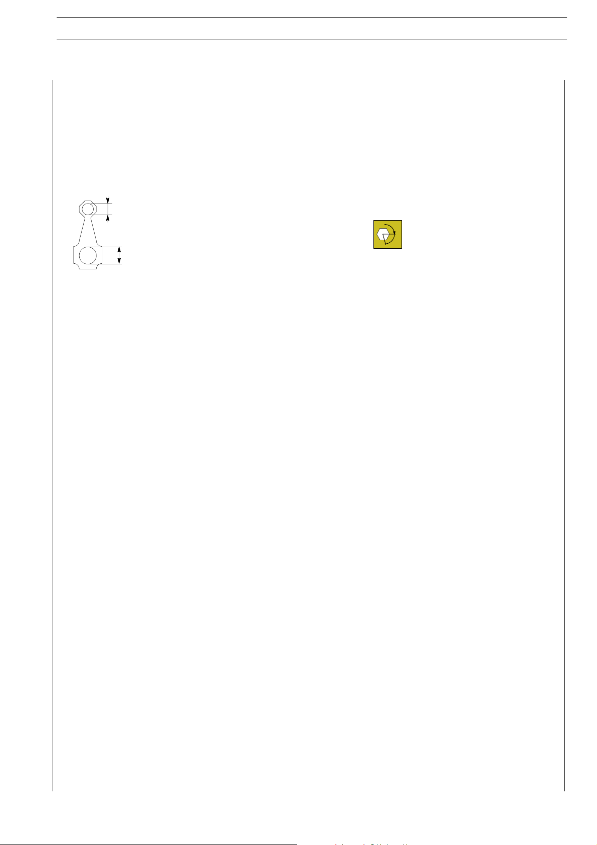
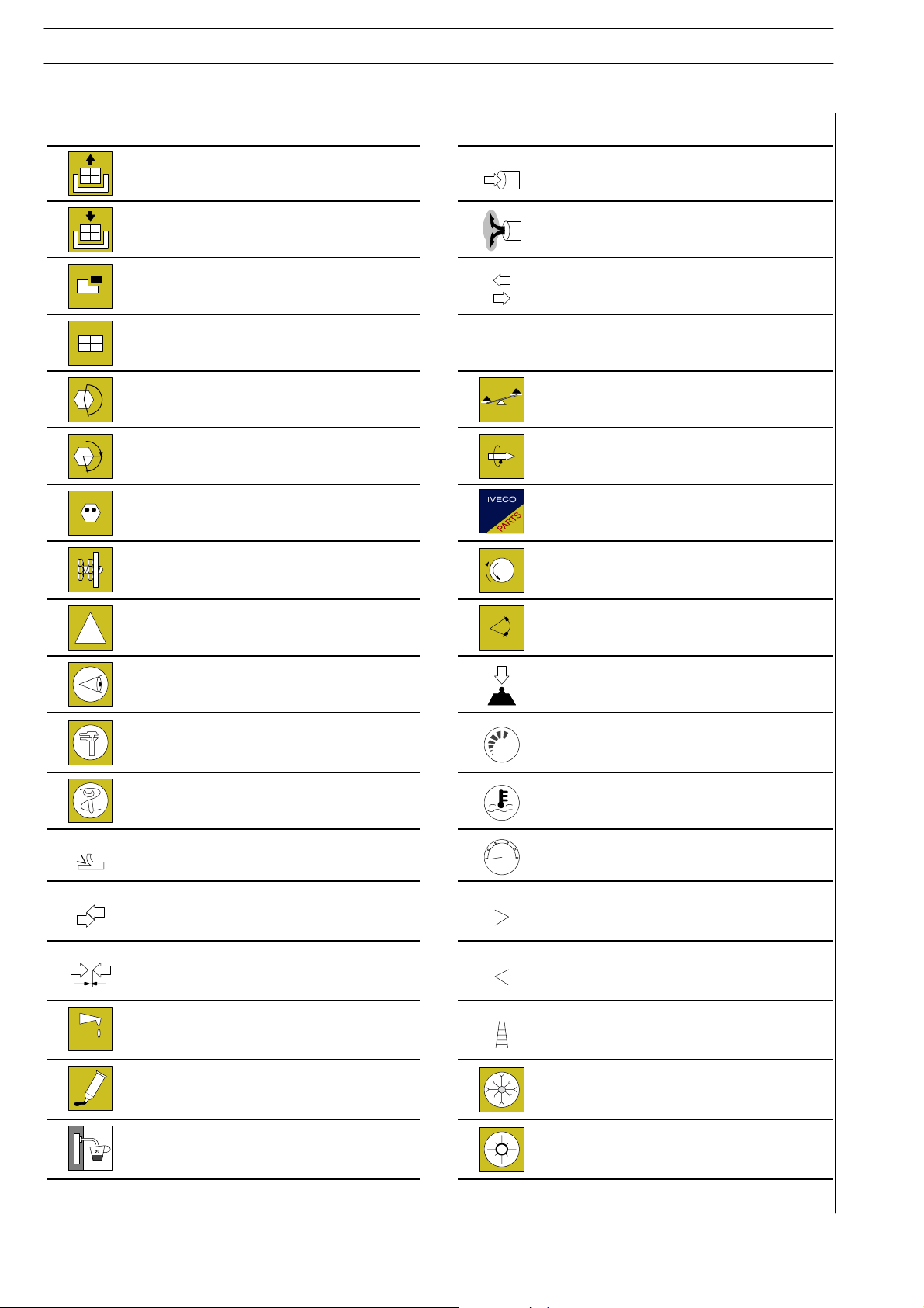
Diagrams and symbols have been widely used to give a clearer and more immediate illustration of the subject being dealt with, (see
next page) instead of giving descriptions of some operations or procedures.
Example
∅
∅
1
Ø 1 = housing for connecting rod small end bush
Tighten to torque
Tighten to torque + angular value
Ø 2 = housing for connecting rod bearings
2
α
Page 6
4
Graph and symbols
ED. FEBRUARY 2003
NEF ENGINES
Removal
Disconnection
Refitting
Connection
Removal
Disassembly
Fitting in place
Assembly
Tighten to torque
Tighten to torque + angle value Rolling torque
α
Press or caulk
Regulation
Adjustment
ρ
Intake
Exhaust
Operation
Compression ratio
Tolerance
Weight difference
Replacement
Original spare parts
Rotation
!
Warning
Note
Visual inspection
Fitting position check
Measurement
Value to find
Check
Equipment Temperature
Surface for machining
Machine finish
Interference
Strained assembly
Thickness
Clearance
Lubrication
Damp
Grease
Sealant
Adhesive
Air bleeding
bar
Angle
Angular value
Preload
Number of revolutions
Pressure
Oversized
Higher than….
Maximum, peak
Undersized
Less than….
Minimum
Selection
Classes
Oversizing
Temperature < 0 °C
Cold
Winter
Temperature > 0 °C
Hot
Summer
Page 7

NEF ENGINES
ED. FEBRUARY 2003
UPDATING
SECTION DESCRIPTION PAGE DATE OF REVISION
5
Page 8
6
ED. FEBRUARY 2003
NEF ENGINES
Page 9

NEF ENGINES SECTION 1 - GENERAL SPECIFICATIONS
ED. FEBRUARY 2003
SECTION 1
General Specifications
ENGINE ID. CODE 3
LUBRICATING CIRCUIT, 4 AND 6 CYLINDERS 5
OIL VAPOUR RECIRCULATING SYSTEM 7
COOLING CIRCUIT SYSTEM, 4 AND 6 CYLINDERS 8
AIR INDUCTION BOOST DIAGRAM 12
1
Page
Page 10

SECTION 1 - GENERAL SPECIFICATIONS
2
ED. FEBRUARY 2003
NEF ENGINES
Page 11
NEF ENGINES SECTION 1 - GENERAL SPECIFICATIONS
ED. FEBRUARY 2003
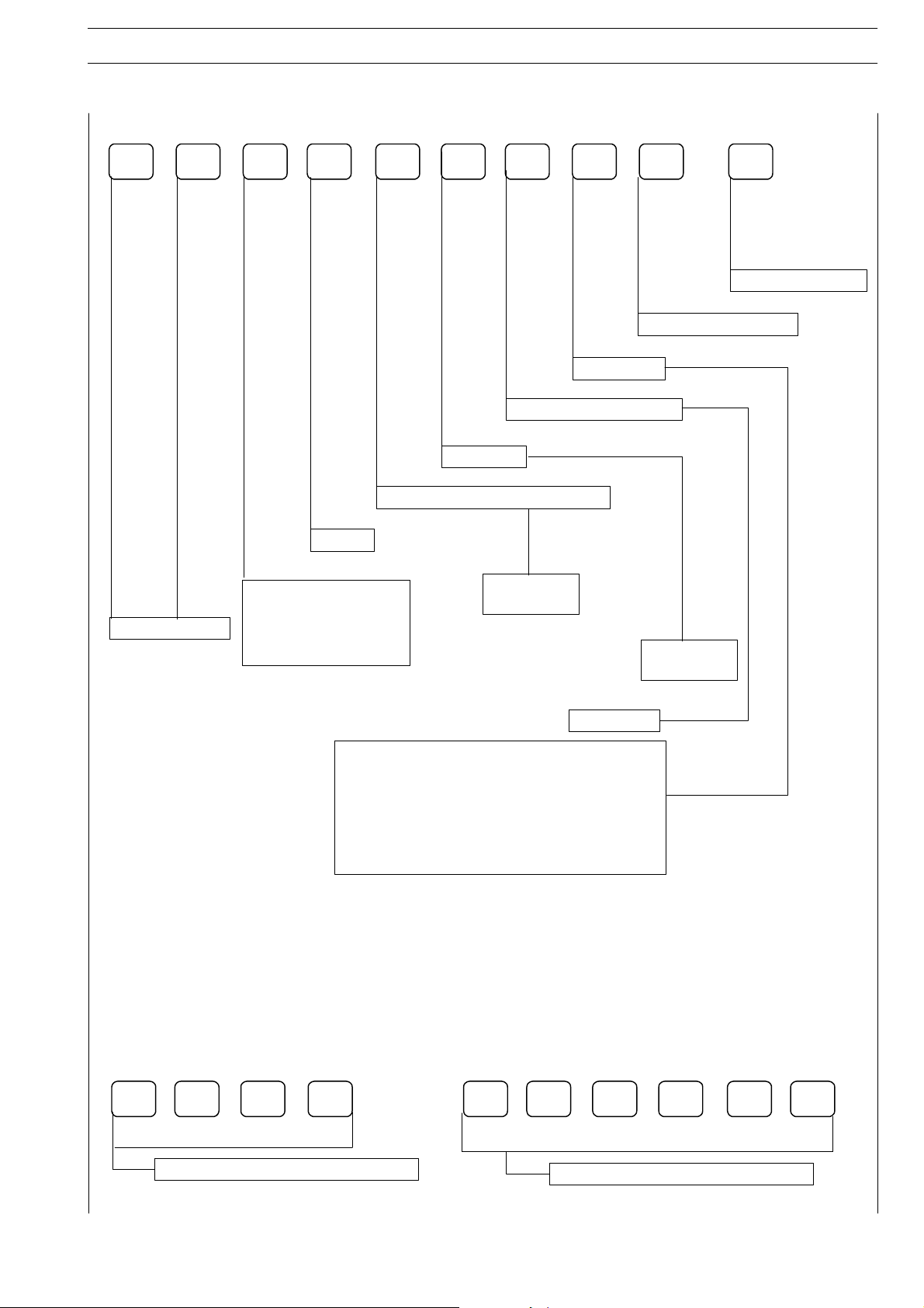
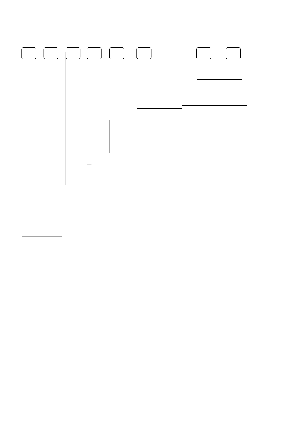
ENGINE IDENTIFICATION CODE
3
F4860EA4DF
Duty No.
Injection
Cylinder No.
Engine cycle — cylinder position
Engine
0=4-stroke,
vertical
Engine series
Type of Engine Block
A = Not struct.
B=Notstruct
C=Struct
*+
Exhaust emiss. level
Homologation power
4=4cylind.
6=6cylind.
0 = Different between the
following applications
1=Truck
2=Bus
3 = Rail rood
4=M.T.vehicles
and tractors
5=Genset
6=Marine
7=Industrial
8=Carsand
9=Army
XY Y Y Y
X = 1 Common Rail 4 valve
8=DI.TCA
and fork lift truck
similar
Y
Y
Model No. within D.B.
Y
Y
Y
Page 12
SECTION 1 - GENERAL SPECIFICATIONS
4
SPECIFIC ENGINE CODE
ED. FEBRUARY 2003
NEF ENGINES
Y
XX
YY Y.Y
Power:
A= Notsuperch.
S = Supercharging
T = Supercharging
with aftercooler
Feed system:
M = Mechanical
E= Electronic
Exhaust emiss. level
Engine block:
N = Not struct.
S= Struct.
XX XX
Engineering code
.
C = Euro3.
E= E(NRMM)
U=EPAUSA
G=Gas
M=Marine
Total displacement or n.
of cylinders
Engine series:
N = Nef Engine
EXAMPLES:
N40ENT.C
N = NEF Engine
40 = 4 liters
E= Electronic
N = Type of Engine block
T = Supercharger with aftercooler
C = Euro3
Page 13
NEF ENGINES SECTION 1 - GENERAL SPECIFICATIONS
ED. FEBRUARY 2003
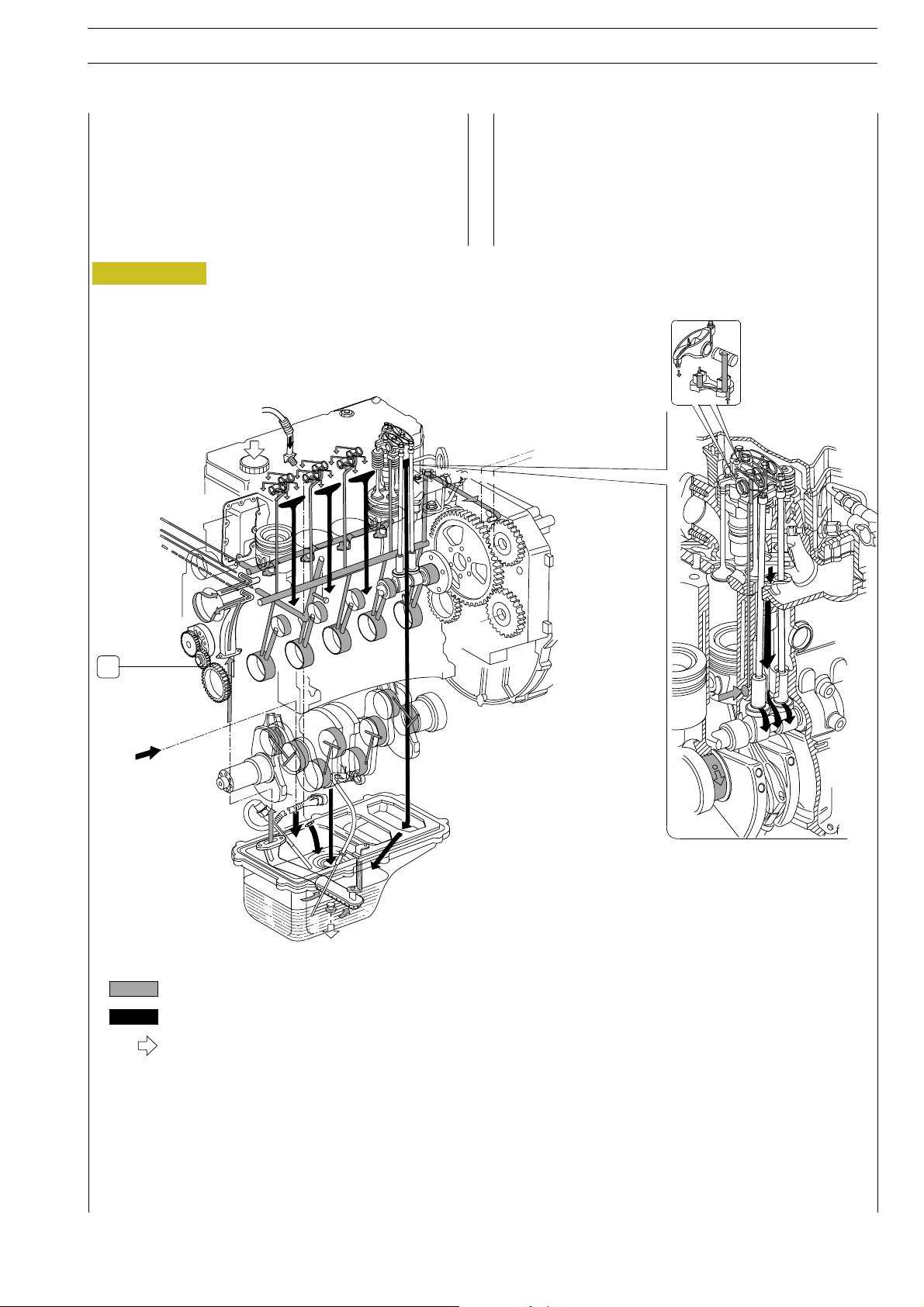
LUBRICATION (4 CYLINDERS)
5
Lubrication by forced circulation is achieved through oil rotary
expansion pump (1), placed in the front part of the basement,
driven by the straight-tooth gear splined to the shaft’s bar hold.
From the pan, the lubrication oil flows to the driving shaft, to
the camshaft and to the valve drive.
Figure 1
Oil recover from the
turbo-blower
To the exchanger and to the
turbo-blower
Lubrication involves the heat exchanger as well, the turboblower and the eventual compressor for any eventual compressed air system. All these components may often vary according to the specific duty and will therefore be examined in
the specific section.
1
Routing of oil under pressure
Routing of oil return by gravity to sump
Introduction of oil
LUBRICATION SYSTEM LAYOUT
Page 14
SECTION 1 - GENERAL SPECIFICATIONS
6
ED. FEBRUARY 2003
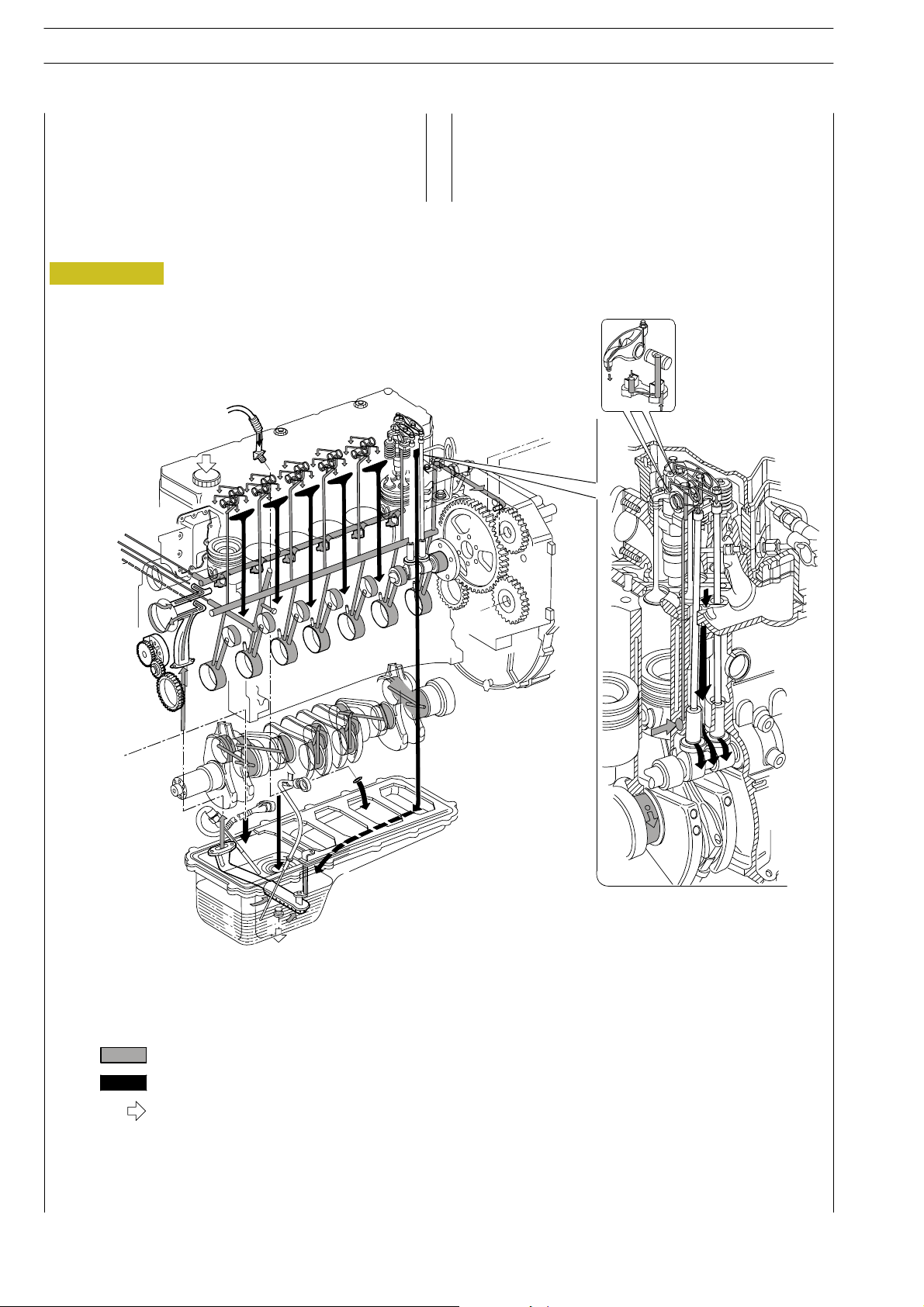
LUBRICATION(6 CYLINDERS)
Even for the 6 cylinders version lubrication is obtained by
forced circulation and achieved through an oil rotary expansion pump similar to the 4 cylinders’ one.
Figure 2
Oil recover from the
turbo-blower
To the exchanger and to the
turbo-blower
NEF ENGINES
Also in this case, the components such as the oil exchanger,
the turbo-blower and the eventual compressor are specifically
studied and made out to suit the equipment or the duty for
which the engine has been developed.
Routing of oil under pressure
Routing of oil return by gravity to sump
Introduction of oil
LUBRICATION SYSTEM LAYOUT
Page 15
NEF ENGINES SECTION 1 - GENERAL SPECIFICATIONS 7
ED. FEBRUARY 2003
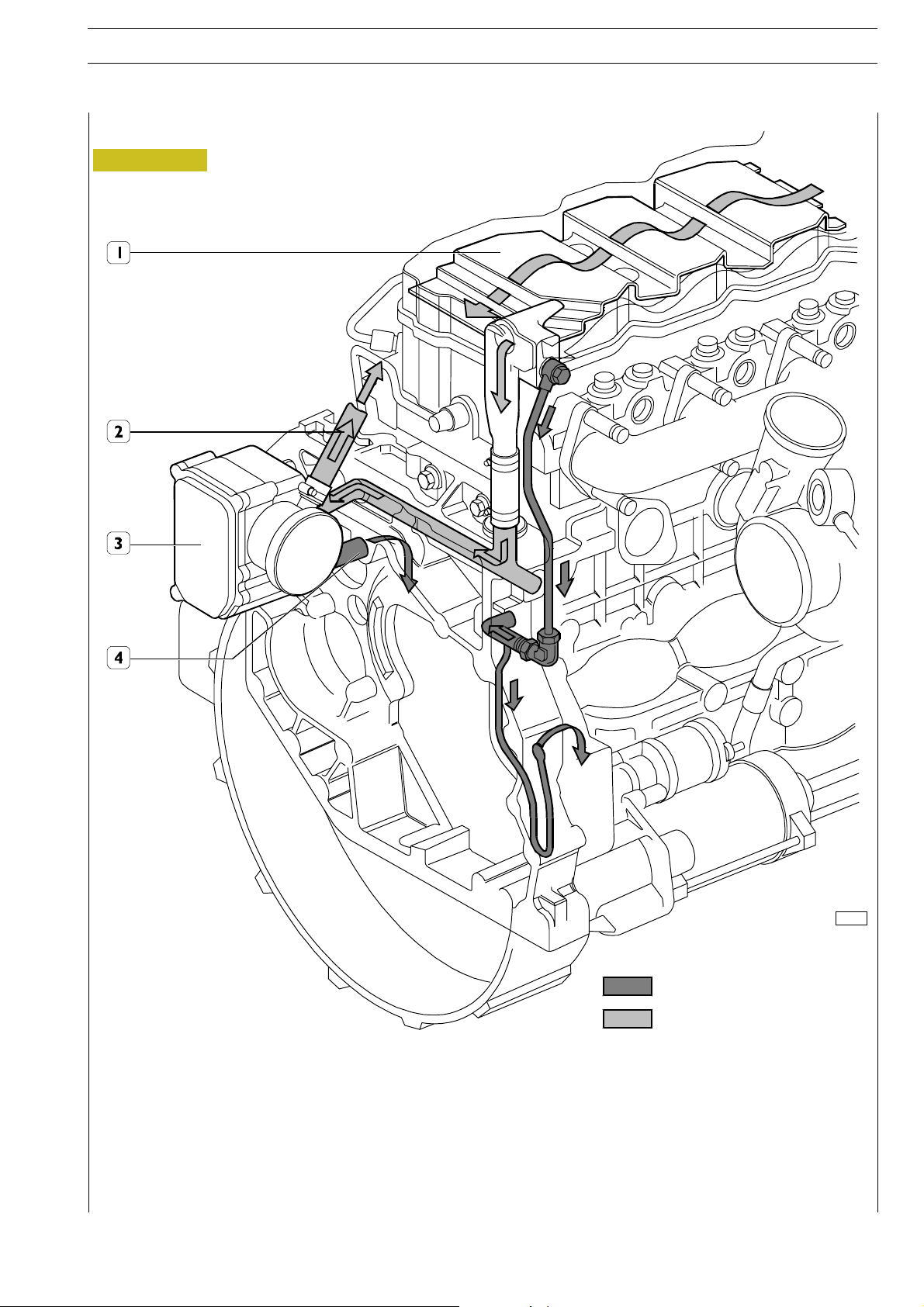
OIL VAPOUR RECYCLING
Figure 3
70484
Oil condensate
Oil vapours
1. Pre-separator - 2. Exhaust to the outside (temporary) - 3. Filter - 4. Return to engine
The tappet cover houses the pre-separator (1), whose shape and position determines an increase in oil vapour outlet speed
and condenses a part of vapours at t he same time.
Condensate oil returns to the oil sump whereas the residual vapours are ducted, collected and filtered in the blow-by (3).
In the blow-by (3), part of the vapours condense and return to the oil sump whereas the remaining part is put into cycle again
through pipe (2).
Page 16
SECTION 1 - GENERAL SPECIFICATIONS
8
ED. FEBRUARY 2003
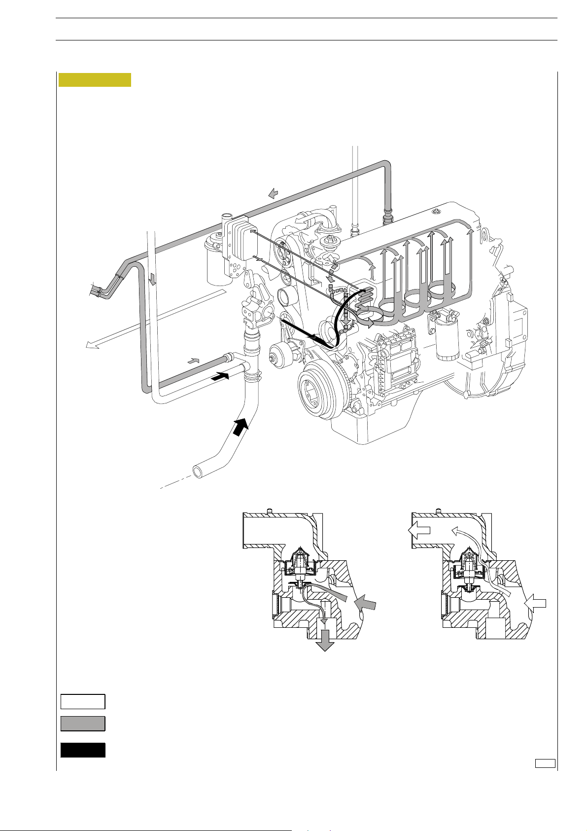
COOLING SYSTEM (4 CYLINDERS)
The engine cooling system, closed circuit forced circulation
type, generally incorporates the following components:
- Expansion tank; placement, shape and dimensions are
subject to change according to the engine’s equipment.
- Radiator, which has the duty to dissipate the heat
subtracted to the engine by the cooling liquid. Also this
component will have specific peculiarities based on the
equipment developed, both for what concerns the
placement and the dimensions.
- Viscous pusher fan, having the duty to increase the heat
dissipating power of the radiator. This component as
well will be specifically equipped based on the engine’s
development.
- Heat exchanger to cool the lubrication oil: even this
component is part of the engine’s specific equipment.
- Centrifugal water pump, placed in the front part of the
engine block.
- Thermostat regulating the circulation of the coolin g
liquid.
- The circuit may eventually be extended to the
compressor, if this is included in the equipment.
NEF ENGINES
Page 17
NEF ENGINES SECTION 1 - GENERAL SPECIFICATIONS 9
ED. FEBRUARY 2003
Figure 4
EXPANSION TANK
EXPANSION TANK
HEATER
(Optional)
RADIATOR
RADIATOR
Water coming out from thermostat
Water recirculating in engine
Water coming into pump
COOLING SYSTEM LAYOUT
74194
Page 18
SECTION 1 - GENERAL SPECIFICATIONS
10
ED. FEBRUARY 2003
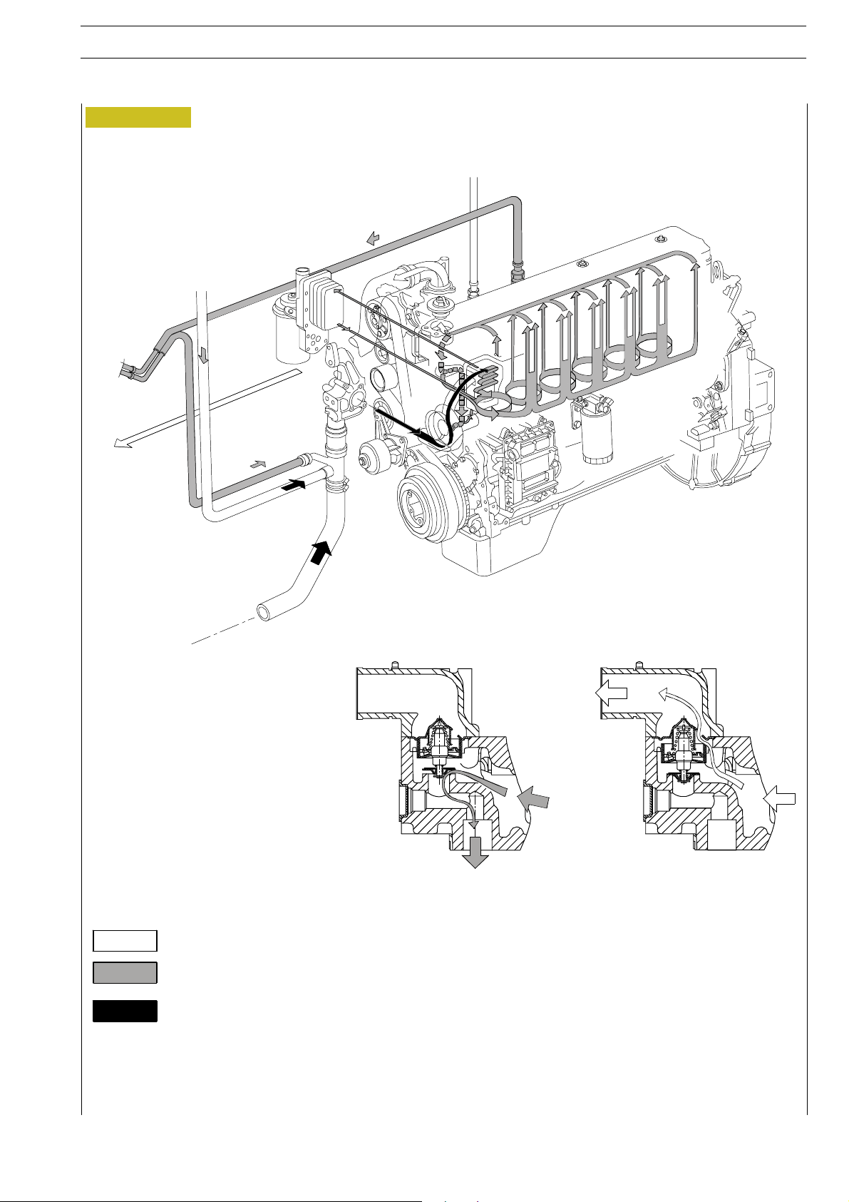
COOLING SYSTEM (6 CYLINDERS)
The engine cooling system, closed circuit forced circulation
type, is of a similar design as the 4 cylinders engine.
It incorporates necessary components such as the radiator,
the heat exchanger, the expansion tank and some ancillary
components such as the h eater or the compressor for the
compressed air.
Such components always vary according to the engine’s
equipment and duty.
NEF ENGINES
Page 19
NEF ENGINES SECTION 1 - GENERAL SPECIFICATIONS 11
ED. FEBRUARY 2003
Figure 5
EXPANSION TANK
EXPANSION TANK
HEATER
(Optional)
RADIATOR
RADIATOR
Water coming out from thermostat
Water recirculating in engine
Water coming into pump
COOLING SYSTEM LAYOUT
Page 20
wnthroughthepist
SECTION 1 - GENERAL SPECIFICATIONS
12
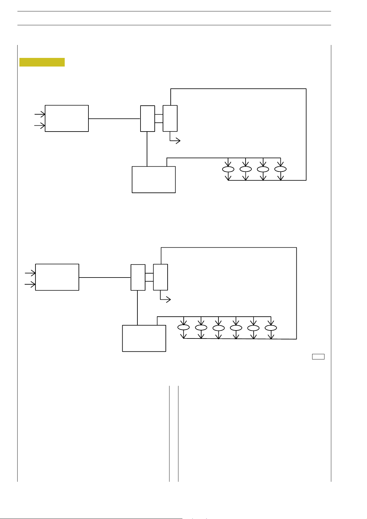
AIR INDUCTION - BOOST DIAGRAM
Figure 6
4 Cylinders version
ED. FEBRUARY 2003
NEF ENGINES
AIR FILTRE
6 Cylinders version
AIR FILTRE
TURBOCHARGER
EXHAUST
RADIATOR
TURBOCHARGER
RADIATOR
Description
The turbocharger is composed by the following main parts:
one turbine, o ne transforming valve to regulate the boost
feeding pressure , o ne main body and one compressor.
During engine working process, the exhaust emissions flow
through the body of the turbine, causing the turbine disk
wheel’s rotation.
The compressor rotor, being connected by shaft to the
turbine disk wheel, rotates as long as this last one rotates,
compressing the drawn air through the air filter.
The above mentioned air is then cooled by the radiator and
flo
on induction collector.
EXHAUST
74195
The turbocharger is equipped with a transforming valve to
regulate the pressure , that i s located on the exhaust
collector before the turbine and connected by piping to the
induction collector.
It’s funchon is to restrict the exhaust of the emissions ,
releasing part of them directly to the exhaust tube when the
boost feeding pressure, over the compressor, reaches the
prescribed bar value.
The cooling process and the lubrication of the turbocharger
and of the bearings is made by the oil of the engine.
Page 21
NEF ENGINES SECTION 2 - FUEL
ED. FEBRUARY 2003
SECTION 2
Fuel
COMMON RAIL 3
WORKING PROCESS 5
FUEL SYSTEM LAYAUT 6
MECHANICAL FUEL PUMP 8
CP3 HIGH PRESSURE PUMP 9
1
Page
RAIL (PRESSURE ACCUMULATOR) 13
BOOST GAUGE VALVE 14
FLOW LIMITERS 15
ELECTRO-INJECTOR 16
PRESSURE LIMITER FOR FUEL RETURN 17
Page 22

2
SECTION 2 - FUEL ED. FEBRUARY 2003
NEF ENGINES
Page 23
NEF ENGINES SECTION 2 - FUEL 3
ED. FEBRUARY 2003
COMMON RAIL
General Specifications
In order to reduce PARTICULATES emissions, very high injection pressures are required.
The Common Rail system allows injecting the fuel up to pressures reaching 1450 bar, at the same time, the injection precision,
obtained by the electronic system control, optimizes the engin e performance, reducing emissions and consumption.
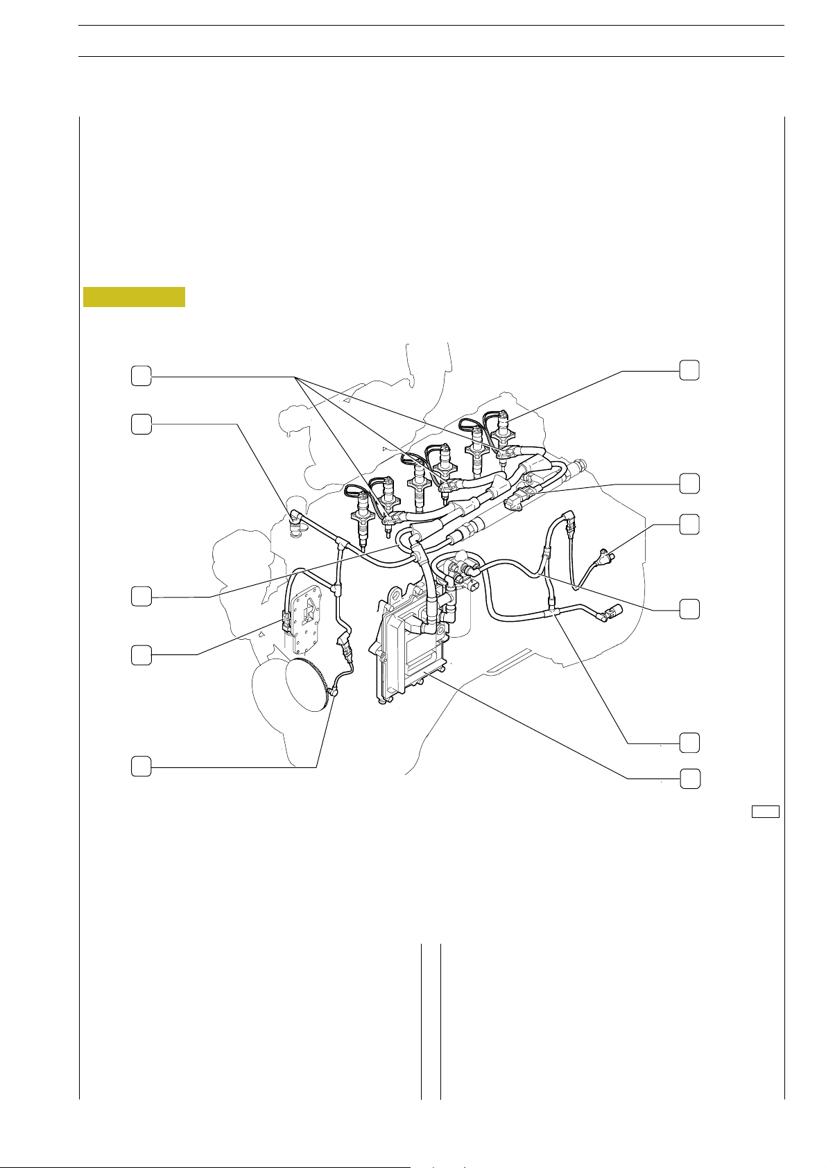
System description
Electric system
Figure 1
1
6
2
7
8
3
9
4
10
5
11
1. Connection to Electro-injectors - 2. Sensor monitoring temperature of engine’s cooling liquid - 3. Fuel pressure sensor
cable - 4. Sensor of engine’s o i l temperature and pressure - 5. Driving shaft sensor - 6. Electro-injector - 7. Temperature
and air pressure sensor - 8. Camshaft sensor - 9. Fuel heater cable and fuel temperature sensor - 10. Pressure gauge cable -
11. EDC 7 gearbox.
Through the sensors, present on the engine, the ECU controls the engine operation.
Air pressure/temperature sensor
It is a component integrating a temperature sensor and a
pressure sensor.
Fitted on the intake manifold, it measures the max. inlet air
capacity to calculate precisely the fuel quantity to inject at
every cycle.
The outlet voltage is proportional to the pressure or temperature obtained by the sensor.
Engine oil temperature and pressure sensor
Same as air pressure/temperature sensor, it is fitted on the
engine oil filter, in a horizontal position.
It measures engine oil temperature and pressure.
74168
Page 24

4
SECTION 2 - FUEL ED. FEBRUARY 2003
NEF ENGINES
Fuel pressure sensor
Assembled on a rail end, it measures the fuel pressure in the
rail in order to determine the injection pressure.
The injection pressure value is used to control the pressure
and to determine the electric injection control length.
Fuel temperature sensor
It is a sensor that is equal to the previous one.
It measures fuel temperature to provide the control unit with
an index of the diesel fuel thermal state.
Coolant temperature sensor
It is a variable-resistance sensor suitable to measure the
coolant temperature to provide the control unit with an
index of the engine thermal state.
Output shaft sensor
It is an inductive sensor placed on the front engine part.
Signals generated through the magnetic flow that is c l osed on
the phonic wheel, change their frequencies depending on
output shaft rotation speed.
Timing sensor
It is an inductive sensor placed on the engine rear left part.
It generates signals obtained from magnetic flow lines that are
closed through holes obtained on the keyed gear on the
camshaft. The signal generated by this sensor is used by the
ECU as injection phase signal.
Though being equal to the flywheel sensor, it is NOT
interchangeable since it has a different outside shape.
Injection control
The control unit, depending on information coming from
sensors, controls the pressure regulator, and changes
pre-injection and main inject ion modes.
Closed-loop control for injection pressure
Depending on engine load, measured by processing signals
coming from various sensors, the control unit controls the
regulator in order to always have the optimum pressure.
Pilot and main injection spark advance control
The control unit, depending on signals coming from various
sensors, computes the optimum injection point according to
an internal mapping.
Idle speed control
The control unit processes signals coming from various
sensors and adjusts the amount of injected fuel.
It controls the pressure regulator and changes t he injection
time of injectors.
Within certain thresholds, it also takes into account the
battery voltage.
Maximum speed limiting
At 2700 rpm, the controlunit limits fuel flow-rate by reducing
the injectors opening time.
Over 3000 rpm it deactivates the injectors.
Cut Off
Fuel cut off upon release is controlled by the control unit
performing the following logics:
- it cuts off injectors supply;
- it re-activates the injectors shortly before idle speed is
reached;
- it controls fuel pressure regulator.
System functionality
Self-diagnosis
The ECU self-diagnostic system checks signals coming from
sensors by comparing them with threshold data.
IVECO Code recognition
The EDC7 control u n it communicates with the Immobilizer
control unit (if fitted) to obtain the startup consent.
Engine pre-heating resistance check
The pre-post heating is activated when even only one of the
water, air or fuel temperature sensors signals a temperature
that is less than 5 °C.
Phase recognition
By means of signals coming from camshaft sensor and
flywheel sensor, the cylinder on which fuel must be injected
is recognised upon startup.
Smoke control upon acceleration
With strong load requests, the control unit, depending on
signals received by air inlet meter and engine speed sensor,
controls t he pressure regulator and changes the injectors
actuation time, in order to avoid exhaust smoke.
Fuel temperature control
When the fuel temperature exceeds 75 °C(measuredbythe
sensor placed on fuel filter) the control unit intervenes by
reducing injection pressure.
If the temperature exceeds 90 °C, the power is reduced to
60%.
AC compressor engagement control
(if fitted)
The control unit is able to drive engagement and
disengagement of the electromagnetic compressor clutch
depending on coolant temperature.
If the coolant temperature reaches about 105 °C, it
disengages the clutch.
After Run
The c on trol unit microprocessor allows storing certain
EPROM data, among which failure memory and Immobilizer
information, in order to make them available upon the
following startup.
Page 25
NEF ENGINES
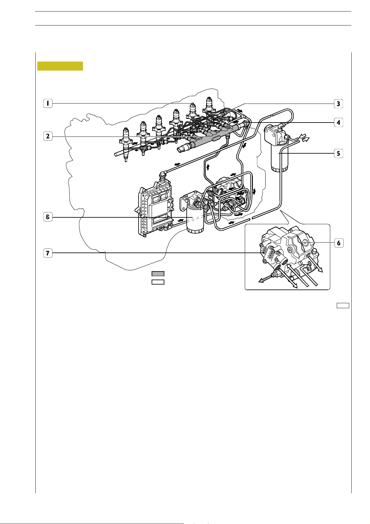
WORKING PROCESS
Figure 2
ED. FEBRUARY 2003
SECTION 2 - FUEL 5
High Pressure
Low Pressure
70492
1. Injector - 2. Common Rail - 3. Pressure limiter for fuel return - 4. Rail overpressure valve - 5. Prefilter assembled on
chassis - 6. High-pressure pump - 7. Mechanical rotor pump - 8. Fuel filter.
The Common Rail system has a special pump that continuously keeps fuel at high pressure, independently from stroke and
cylinder that has to receive the injection and accumulates fuel in a common duct for all injectors.
Therefore, fuel at the injection pressure computed by the ECU is always available at the injectors inlet.
When an injec t or solenoid valve is energised by the electronic control unit, the injection of fuel directly taken from rail takes
place in the related cylin der.
The hydraulic system is implemented by a low-pressure circuit and a high-pressure c ircuit.
The high-pressure circuit is composed of the following pipings:
- piping connecting high-pressure pump outlet to rail;
- pipings supplying injectors from rail.
The low-pressure circuit is composed of the following pipings:
- fuel suction piping from tank to prefilter;
- pipings supplying the mechanical supply pump through the control unit heat exchanger, manual priming pump and prefilter;
- pipings supplying the high-pressure pump through the fuel filter.
The fuel draining circuit from rail and from injectors and the high-pressure pump cooling circuit complete the system.
Page 26

6
SECTION 2 - FUEL ED. FEBRUARY 2003
FUEL SYSTEM LAYOUT
This fuel system is a Common Rail injection with CP3 high
pressure pump and this layout is for 4 cylinder version.
(The 6 cylinder version is similar design as the 4 cylinder engine).
The pressure regulator, placed upstream of the high-pressure
pump, adjusts the fuel flow that is necessary on the low-pressure system. Afterwards, the high-pressure pump takes care
of supplying the rail properly. This arrangement, by pressurising the necessary fuel only, improves the energetic efficiency
and limits fuel heating in the system.
Function of the pressure relief valve (2), assembled on the
high-pressure pump, is keeping the pressure, at t he pressure
regulator inlet, constant at 5 bars, independently from the
efficiency of the fuel filter and of the system set upstream.
The pressure relief valve (2) intervention brings about a fuel
flow increase in the high-pressure pump cooling circuit,
through inlet and drain piping (16) from piping (8).
The pressure relief valve housed on the cylinder head, assembled on injector return (3), limits the fuel return flow
from injectors at a pressure of 1.3 to 2 bars.
Two by-pass valves are placed in parallel with the mechanical
supply pump.
The by-pass valve (18) allows fuel to flow from mechanical
pump outlet to its inlet, when the fuel filter inlet pressure exceeds the allowed threshold value.
The by-pass valve (17) allows filling the supply system
through the manual priming pump (10).
NEF ENGINES
1. High-pressure pump. — 2. Pressure relief valve on high-pressure pump, 5 bars. — 3. Pressure relief valve assembled on fuel return
from injectors, 1.3 to 2 bars. — 4. Rail overpressure valve. — 5. Common Rail. — 6. Pressure sensor. — 7. Injector. — 8. Return piping.
— 9. Control unit heat exchanger. — 10. Mechanical priming pump. — 11. Prefilter assembled on chassis. —
12. Fuel tank. — 13. Mechanical supply pump. — 14. Fuel filter. — 15. Pressure regulator. — 16. High-pressure pump cooling piping.
— 17. By-pass valve. — 18. By-pass valve.
Page 27
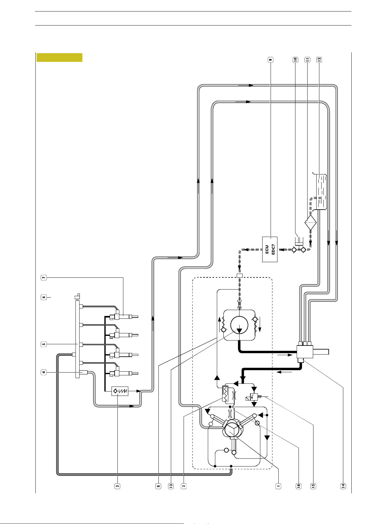
NEF ENGINES SECTION 2 - FUEL 7
ED. FEBRUARY 2003
Figure 3
Page 28
8
SECTION 2 - FUEL ED. FEBRUARY 2003
NEF ENGINES
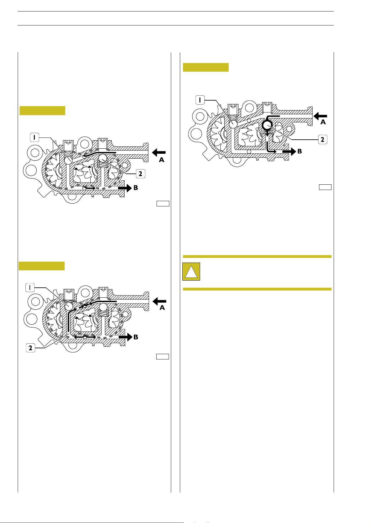
MECHANICAL FEEDING PUMP
Gear pump, placed on rear part of the high pressure pump,
whose function is to feed the high pressure pump. It is driven
by the high pressure pump’s shaft.
Ordinary working condition
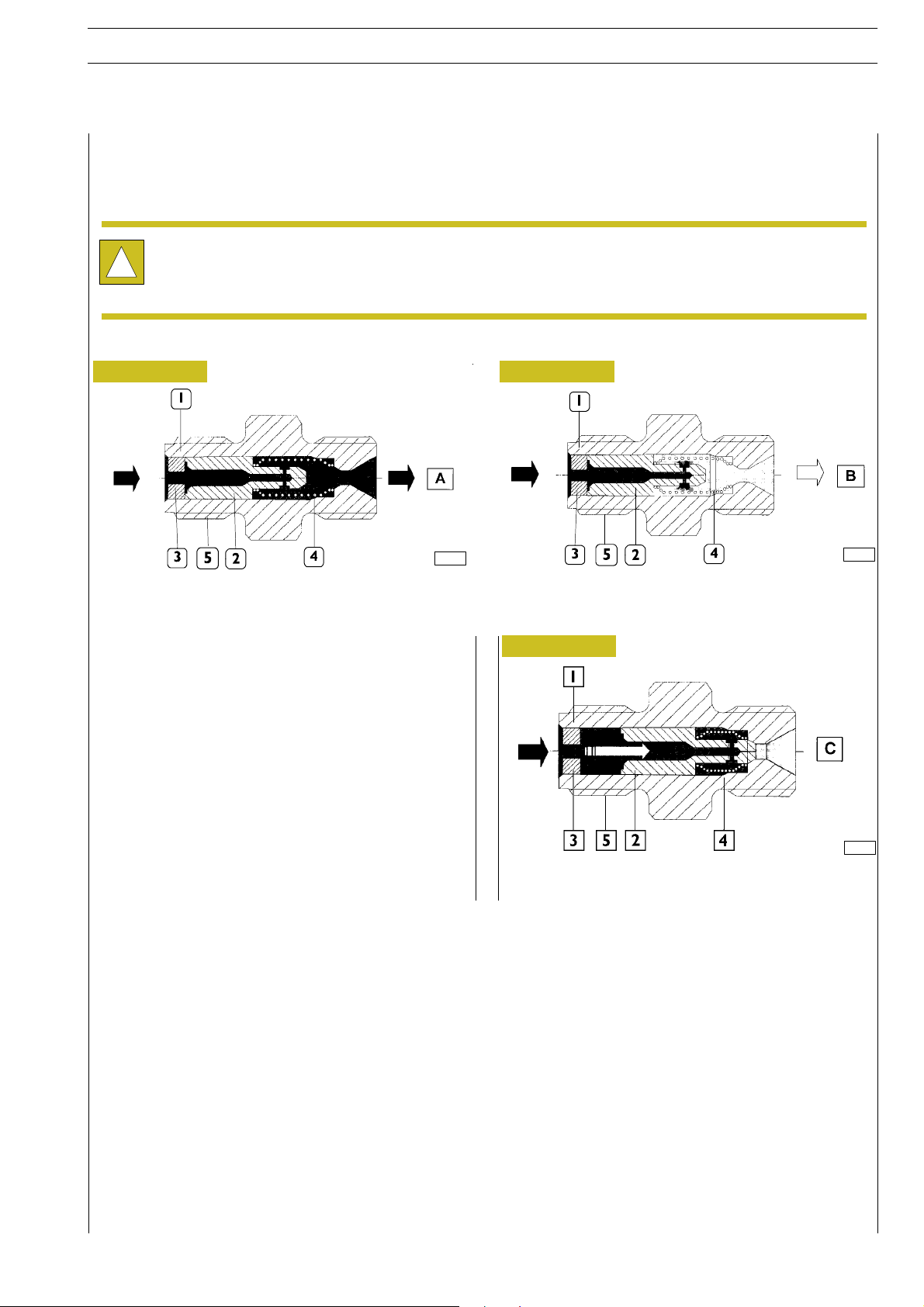
Figure 4
72592
A- Fuel entry flowing from the tank. B- Fuel exhaust to filter,
I - 2 By-pass valves in close position.
Jettison condition
Figure 6
72594
The dump by-pass valve (2) is activated in case, when the
engine is off, it is necessary to fill the feeding system through
the priming pump. In this condition the by pass valve (I) keeps
closed while the dump by-pass valve (2) opens up due to the
pressure effect on the entry unit so the fuel flows to the
exhaust unit B.
Overpressure condition in Exhaust unit
Figure 5
72593
The by-pass valve (I) is activated in case of overpressure on B
Exhaust unit. The actual pressure, overcoming the resistance
of the valve’s spring (I), connects the exhaust with the entry
through the gallery (2).
The mechanical feeding pump cannot be replaced
separately, therefore it must not be disassembled
!
from the high pressure pump.
Page 29
NEF ENGINES SECTION 2 - FUEL 9
ED. FEBRUARY 2003
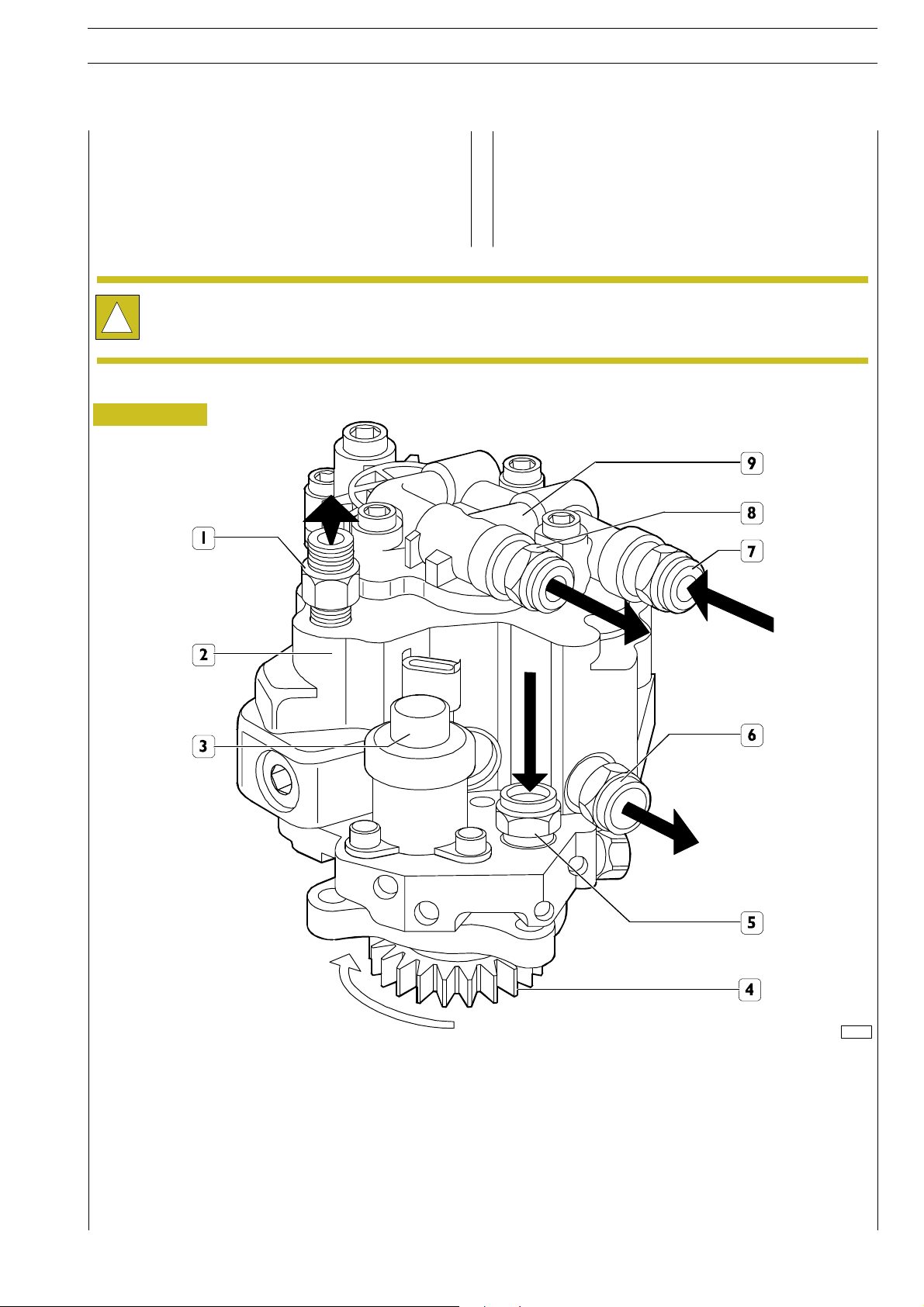
CP3 HIGH PRESSURE PUMP
Pump provided with 3 radial pumping elements driven by the
timing system gear, no need of timing. The mechanic al feeding
pump driven by the high pressure pump’s shaft is assembled
to the rear side of the high pressure pump.
The high pressure pump unit - feeding pump is not subject to overhaul , therefore it must not be disassembled neither
the fixing screws must be tampered.The only operation allowed is the replacement of the driving gear.
!
Figure 7
72595
1. Fuel exhaust connector to rail - 2. High pressure pump - 3. Pressure regulat i ng gauge - 4. Driving gear - 5. Connector to
fuel entry flowing from filter - 6. Connector to fuel exhaust to filter support - 7. Connector to fuel entry flowing from engine
control module heat exchanger - 8. Connector to fuel exhaust flowing from mechanic pump to filter - 9. Mechanical feeding
pump.
Page 30
10
SECTION 2 - FUEL ED. FEBRUARY 2003
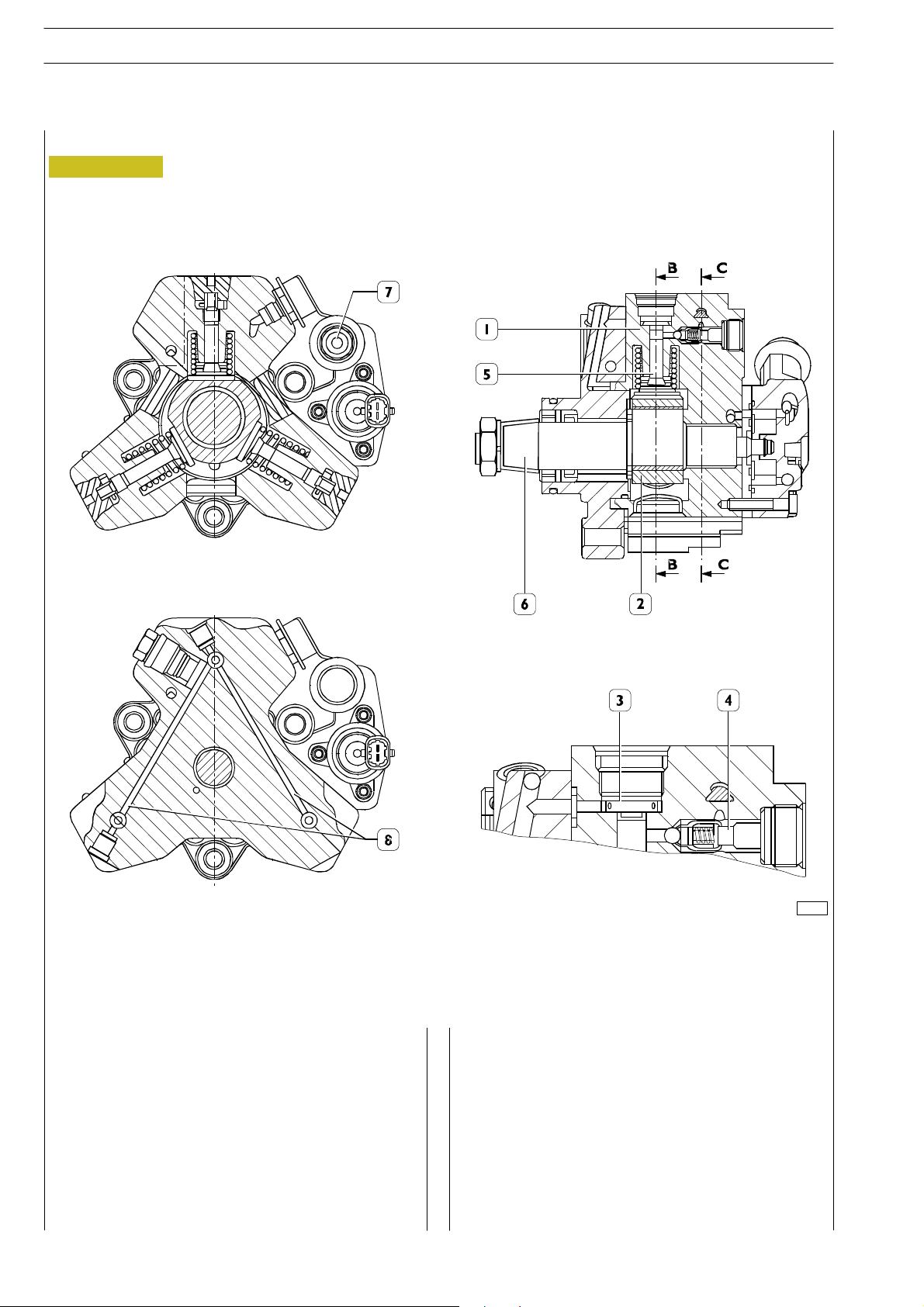
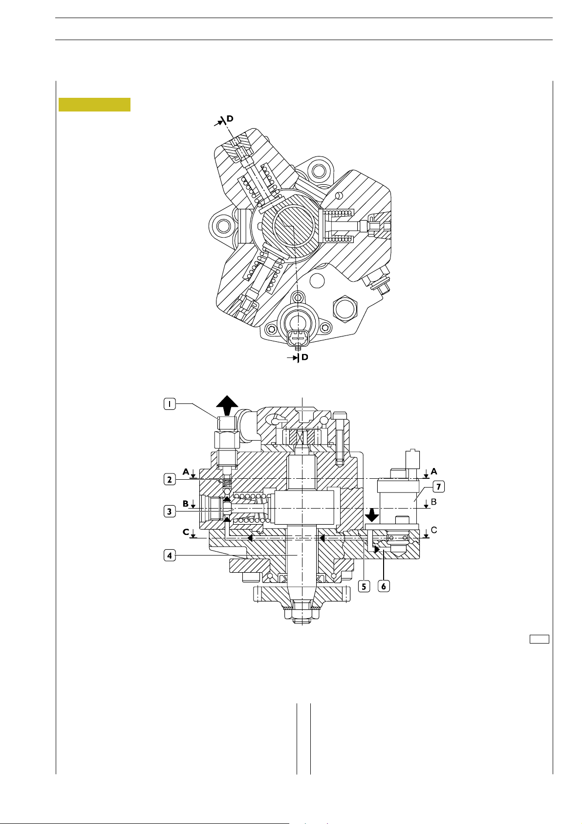
High pressure pump-inside structure
Figure 8
Sec. B-B
NEF ENGINES
Sec. C-C
1. Cylinder. — 2. Three-lobe element. — 3. Cap intake valve. — 4. Ball delivery valve. — 5. Piston. — 6- Pump shaft. —
7. Low-pressure fuel inlet. — 8. Pumping elements supplying fuel ducts.
70498
Every pumping unit is composed of:
- a piston (5) actuated by a three-lobe element (2) floating
on the pump shaft (6). The element (2), being floating on
a misaligned part o f the shaft (6), when the shaft rotates,
does not rotate therewith but is only translated in a
circular movement along a wider radius, with the
resulting alternate actuation of the three pumping
elements;
- cap intake valve (3);
- ball delivery valve (4).
Page 31
NEF ENGINES SECTION 2 - FUEL 11
ED. FEBRUARY 2003
Working principle
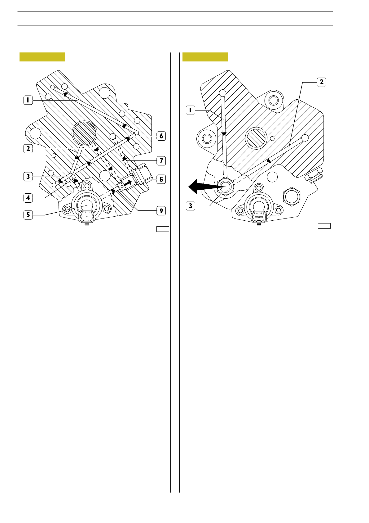
Figure 9
Sec. B - B
Sec. D - D
72597
1. Cylinder. — 2. Three-lobe element. — 3. Cap intake valve. — 4. Ball delivery valve. — 5. Piston. — 6- Pump shaft. —
7. Low-pressure fuel inlet. — 8. Pumping elements supplying fuel ducts.
The pumping element (3) is orientated towards the pump’s
camshaft (4). During the intake phase, the pumping element
is fed through the feeding line (5). The quantity of fuel to flow
to the pumping element is determined by the pressure
During compression phase of the pumping element, the fuel
achieves the level of pressure determining the opening of the
by-pass valve to co mmon rail (2), feeding it through the
exhaust unit (I).
regulating gauge (7). The pressure regulating gauge,
according to the PWM command received by the engine
control module, stops the fuel flow to the pumping element.
Page 32
12
SECTION 2 - FUEL ED. FEBRUARY 2003
NEF ENGINES
Figure 10
Sec. C - C
72598
Figure 11
72601
Sec. A - A
1. Cylinder. — 2. Three-lobe element. — 3. Cap int ake valve.
— 4. Ball delivery valve. — 5. Piston. — 6- Pump sh aft. —
7. Low-pressure fuel inlet. — 8. Pumping elements supplying
fuel ducts.
Picture 10 shows the fuel runs at low pressure inside the
pump; the following elements are clearly visible: the main
feeding line to the pumping elements (4); the feeding lines to
the pumping elements (1-3-6), the duct lines run for the
pump lubrication (2), the pressure gauge (5), the flow limiting
valve to 5 bar (8) and the fuel exhaust flue (7).
The pump shaft is lubricated by the fuel through the feeding
and recovery lines.
The pressure gauge (5) determines the quantity of fu el to
feed the pumping elements: the fuel in excess flows through
the exhaust gallery (9).
The limiting valve to 5 bar, in addition to recovering fuel
exhaust as a collector has also function to keep the pressure
constant to 5 bar limit at gauge entry.
1. Fuel exhaust flue - 2. Fuel exhaust gallery - 3 Fuel
exhaust flowing from pump with connector to high
pressure pipe for common rail.
Picture 11 shows the fuel flow under high pressure running
through the exhaust galleries of the pumping elements.
Page 33
NEF ENGINES SECTION 2 - FUEL 13
ED. FEBRUARY 2003
Operation
The cylinder is filled through the cap intake valve only if the
supply pressure is suitable to open the delivery valves set on
the pumping elements (about 2 bars).
The amount of fuel supplying the high-pressure pump is
metered by the pressure regulator, placed o n the
low-pressure system; the pressure regulator is controlled by
the EDC7 control unit through a PWM signal.
When fuel is sent to a pumping element, the related piston
is moving downwards (suction stroke). When the piston
stroke is reversed, the intake valve closes and the remaining
fuel in the pumping element chamber, not being able to come
out, is compressed above the supply pressure value existing
in the rail.
The thereby-generated pressure makes the exhaust valve
open and the compressed fuel reaches the high-pressure
circuit.
The pumping element compresses the fuel till the top dead
center (delivery stroke) is reached. Afterwards, the pressure
decreases till the exhaust valve is closed.
The pumping element piston goes back towards the bottom
dead center and the remaining fuel is decompressed.
When the pumping element chamber pressure becomes less
than the supply pressure, the intake valve is again opened an d
the cycle is repeated.
The delivery valves must always be free in their movements,
free from impurities and oxidation.
The rail delivery pressure is modulated between 250 and
1350 bars by the electronic control unit, through the
pressure regulator solenoid valve.
The pump is lubricated and cooled by the fuel.
The radialjet pump disconnection — reconnection time on
the engine is highly reduced in comparison with traditional
injection pumps, because it does not require setting.
If the pipe between fuel filter and high-pressure pump is to
be removed-refitted, be sure that hands and components are
absolutely clean.
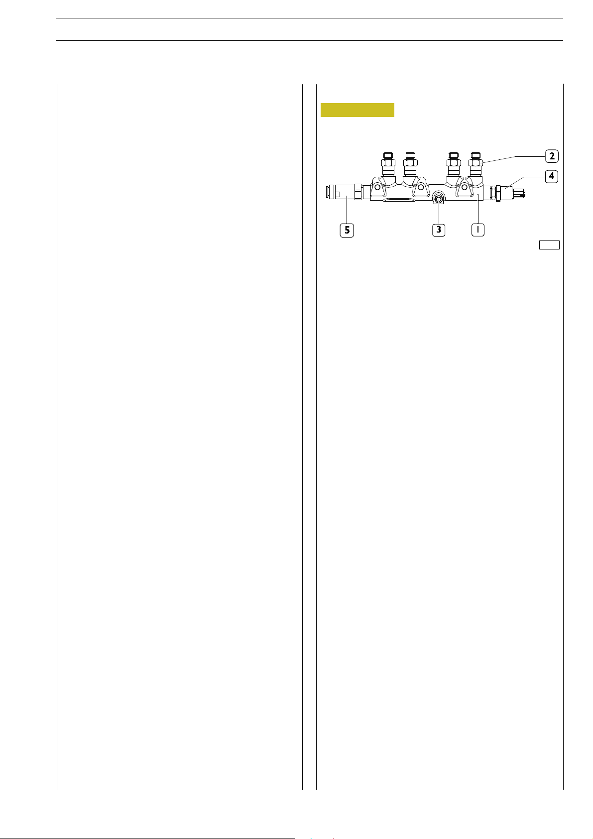
RAIL
Figure 12
70499
1. Rail. — 2. Flow limiters. — 3. Fuel inlet from high-pressure
pump. — 4. Pressure sensor. — 5. Overpressure valve.
The rail volume is comparatively small to allow a quick
pressurisation at startup, at idle and in case of high flow-rates.
It anyway has enough volume as to minimise system spikes
and the use of plenum chambers caused by injectors
openings and closings and by the high-pressure pump
operation. This function is further enabled by a calibrated
hole being set downstream of the high-pressure pump.
A fuel pressure sen sor (4) is screwed to the rail. The signal
sent by this sensor to the electronic control unit is a
feed-back information, depending on which the rail pressure
value is checked and, if necessary, corrected.
Page 34
14
SECTION 2 - FUEL ED. FEBRUARY 2003
NEF ENGINES
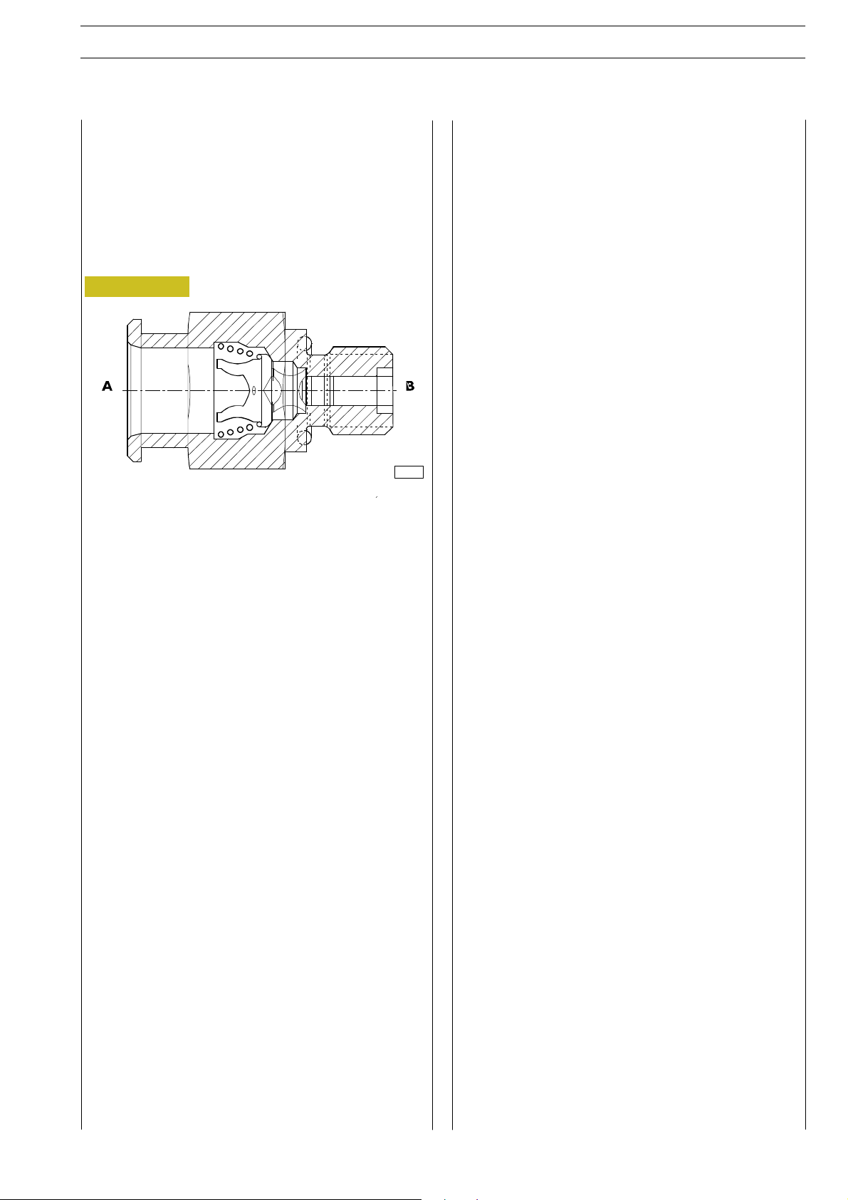
BOOST GAUGE VALVE
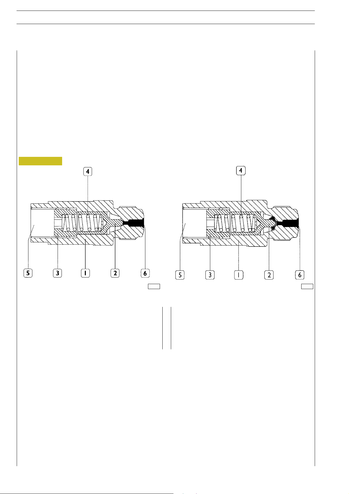
The boost valve (1750 bars) is assembled to the rail with the purpose to protect the system’s components in case of excessive
increase of pressure within the high pressure system. Pressure limiter.
The valve can be single-stage (as the one showed in the picture) or double-stage with double working limit (1750 bars and 800
bars).
In the second c ase, when the pressure within the high pressure system reaches 1750 bars, the valve is activated as a single-stage
one to exhaust the fuel and consequently reduce the pressure until reaching safety parameters. Then it provides mechanically
gauging the pressure into rail to aprx. 800 bars. This way the valve enables working of the engine for extended timing at limited
performances, avoiding the fuel’s overheating and preserving the exhaust gal leries.
If the above mentioned valve is activated, the engine control module excludes by isolat ion the pressure gauge and records the
errore code 8.4.
The pump will flow the maximum delivery to the rail.
Figure 13
A
70500
1. Body — 2. S mall piston — 3. Stop — 4. Spring — 5. Direct tank discharge — 6. Seat on rail.
A Normally, the tapered piston end keeps closed the
discharge towards the tank.
B If the 1750 bar fuel pressure is exceeded in rail, the small
piston is displaced and the excess pressure is discharged
into the tank.
B
70502
Page 35
NEF ENGINES SECTION 2 - FUEL 15
ED. FEBRUARY 2003
FLOW LIMITERS
They are placed on rail fuel outlet fittings, and are used to protect engine or vehicle in tegrity in case of internal leaks (for example,
locked-open spray nozzle) or external leaks (example: damaged high-pressure pipings).
In such cases, system operation is, within certain limits, allowed through components remained unaffected in other cylinders.
After having blocked fuel from going out of the rail, the flow limiter is automatically re-primed under spring operation.
If however the reason for its intervention is not removed, upon the following startup attempt, the engine could
!
operate only at idling or at low speeds or be again turned off depending on the amount of leakage.
Figure 14 Figure 15
70501
1. Body — 2. Small piston — 3. Fuel inlet — 4. Spring — 5. Rail-securing threading.
A The passage of fuel from rail to injectors is implemented
through holes obtained on the small piston diameter.
Figure 16
Under normal conditions, fuel pressure operates on the
two piston sides, kept opened by the spring.
B In case of st rong pressure leaks downstream of the
limiter, the inlet pressure becomes greater and displaces
the piston to the opposite side, closing fuel outlet.
C Limiter with piston in outlet c losin g position.
70503
70504
Page 36
16
SECTION 2 - FUEL ED. FEBRUARY 2003
NEF ENGINES
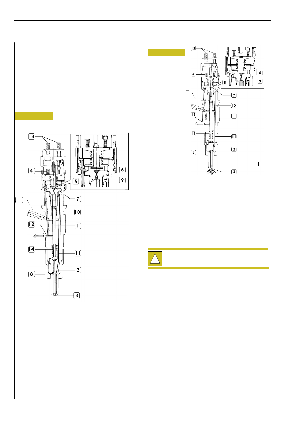
ELECTRO-INJECTOR
The injector is similar as construction to the traditional on es,
apart from the absence of plunger return springs.
The injector can be deemed as composed of two parts:
- actuator — spray nozzle composed of pressure rod (1),
plunger (2) and nozzle (3);
- control solenoid valve composed of coil (4) and pilot
valve (5).
The solenoid valve controls spray nozzle plunger lift.
Injector in rest position
Figure 17
15
Injection start
Figure 18
15
70506
When coil (4) is energised, it makes shutter (6) move
upwards. The control volume (9) fuel flows towards flow
duct (12) making a pressure drop occur in c ontrol volume
(9). Simultaneously the fuel pressure in to pressure chamber
(8) makes plunger (2) lift, with followin g fuel injection into the
cylinder.
70505
1. Pressure rod — 2. Plunger — 3. Nozzle — 4. Coil — 5. Pilot
valve — 6. Ball shutter — 7. Control area — 8. Pressure
chamber — 9. Control volume — 10. Control duct — 11.
Supply duct — 12. Control fuel outlet — 13. Electric
connection — 14. Spring — 15. High-pressure fuel in let.
Injection end
When coil (4) is de-energised, shutter (6) goes back to its
closing position, in order to re-create suc h a force balance as
to make plunger (2) go back t o its closing position and end
the injection.
The injector cannot be overhauled and therefore it
must not be disassembled.
!
Page 37
NEF ENGINES SECTION 2 - FUEL 17
ED. FEBRUARY 2003
PRESSURE LIMITER FOR FUEL RETURN
It is housed on the rear of the cylinder head, and adjusts the
pressure of fuel returning from injectors at a pressure 1.3 and
2 bars. By guaranteeing this pressure to the return fuel, the
fuel vapours formation inside injectors is avoided, optimising
fuel spraying and combustion.
Figure 19
A To tank — B From in ject ors
70507
Page 38

18
SECTION 2 - FUEL ED. FEBRUARY 2003
NEF ENGINES
Page 39
NEF ENGINES SECTION 3 - DUTY - INDUSTRIAL EQUIPMENT
HYDRAULIC SYSTEM - BRAKES
ED. FEBRUARY 2003
SECTION 3
Duty - Industrial equipment
GENERAL SPECIFICATIONS 3
- Sect ion pictures o f complete engine
Common rail version 3
- Clearance data 4-6 cyl. 4
PART ONE - MECHANICAL COMPONENTS 7
ENGINE OVERHAUL 9
- Preface 9
- Engine setting operations for the assembly
on turning stand 9
- Disassembly of application components 10
1
Pagina
- Assembly of application components 17
- Completion of the Engine 29
- Checks inspection and c ontrol 30
TIGHTENING TORQUE 31
PART TWO - ELECTRICAL EQUIPMENT 33
- Placement of sensors 35
- EDC7 ECU 36
- Connect or to in ject ors 37
- Feed connector to components and to functions
of the specific equipment 38
- Connector to sensors 39
- Temperature and air pressure sensor 40
- Sensor of engine’s oi l temperature and pressure 40
- Driving sh aft sensor 40
- Timing system sensor 40
- Fuel pressure sensor 41
- Fuel temperature sensor 41
- Resistor pre-post heating 41
- Cooling liquid temperature sensor 41
- Starter 42
- Electro-injectors 42
Page 40
2
SECTION 3 - DUTY - INDUSTRIAL EQUIPMENT
ED. FEBRUARY 2003
NEF ENGINES
Pagina
PART THREE - TROUBLESHOOTING 43
PREFACE 45
BLINK-CODE - GENERAL INFORMATION 46
- Anomaly warning led 46
- Detectable errors 46
BLINK-CODE - (3.3_I SOFTWARE VERSION) 47
- Recovery 47
GUIDELINES FOR TROUBLESHOOTING
WITH PT-01 PORTABLE TESTER 61
PT-01 PORTABLE TESTER 63
- Main functions 63
- Test parameters 63
FAILURE CODES (3.3_1 SOFTWARE VERSION) 64
FAILURE CODES (4.1_2 SOFTWARE VERSION) 67
GUIDELINES FOR TROUBLESHOOTING
WITHOUT BLINK CODE 71
Pagina
PART FOUR - MAINTENANCE PLANNING 75
- Recovery 77
- Regular maintenance and inspection planning 77
- Checks not included in maintenance planning -
daily checks 78
MAINTENANCE PROCEDURES - CHECKS
AND INSPECTIONS 78
- Checks an d inspection 78
- Engine oil level check 78
- Combustion sy stem inspection 79
- Cooling system inspection 79
- Lu bricating system inspection 79
- Check of water presence within fuel
filter or pre-filter 79
- Inspection / replacement of blow-by filter 80
- Inspection of drive belt tensioning 80
- Inspection and setting of tappet clearance 80
Page 41
NEF ENGINES SECTION 3 - DUTY - INDUSTRIAL EQUIPMENT 3
ED. FEBRUARY 2003
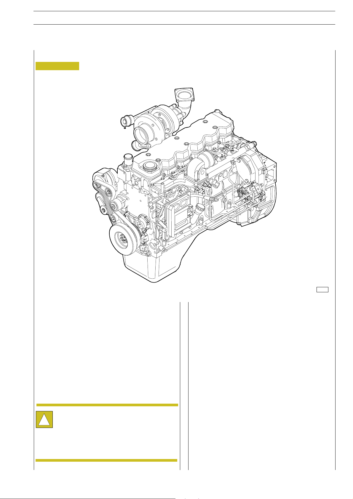
GENERAL SPECIFICATIONS
Section pictures of complete engine - common rail version
Figure 1
The NEF F4AE0484 and F4AE0684 engines are turbocharged
a 4-stroke diesel engines with 6 cylinders or 4 cylinders, with
4 valves per cylinder.
They have high pressure injection fuelling (common rail) and
are entirely electronically driven in order to optimise the
working process in accordance to the operation, limiting as
much as possible the pollution emissions and consumption.
Data, features and performances are valid only if the
setter fully complies with all the installation
!
prescriptions provided by IVECO.
Furthermore, the users assembled by the setter shall
always be in conformance to couple, power and
number of turns based on which the engine has been
designed.
74184
The section herein described is composed or four sections:
- Section of mechanical overhaul prescribed in accordance
to the engine’s specific duty, illustrating all necessary
operation to remove and assembly the external
components of the engine, including cylinder heads,
gearbox of the timing system and of the front part cover;
- Electrical section, describing the connections to the
different components of the engine control module and
of the sensors assembled to the engine;
- Diagnosis section;
- Section of preventive maintenance operations, providing
instructions for the execution of the main operations.
Page 42
4
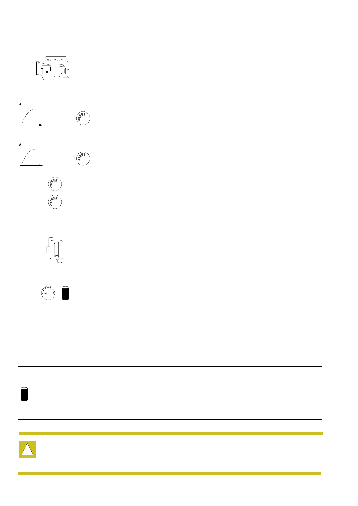
F4AE0484B*D
1
SECTION 3 - DUTY - INDUSTRIAL EQUIPMENT
CLEARANCE DATA - 4 CYL.
ED. FEBRUARY 2003
NEF ENGINES
ρ
Type
Compression ratio
Max. output kW
(HP)
rpm
Max. torque Nm
(kgm)
rpm
Loadless engine
idling rpm
Loadless engine
peak rpm
Borexstroke
Displacement
TURBOCHARGING
*
17 : 1
107
145
2300
-
-
-
-
-
102 x 120
3920
with intercooler
bar
15W40 ACEA E3
Turbocharger type
LUBRICATION
Oil pressure (warm engine)
- idling bar
- peak rpm bar
COOLING
Water pump control
Thermostat
- start of opening ºC
FILLING
engine sump liters
engine sump + filter liters
GARRETT GT 22
Forced by gear pump, relief valve single action
oil filter
0.7
4.0
By centrifugal pump, regulating thermostat, heat
exchanger, intercooler
Through belt
82.2
5.3
6.3
Data, features and performances are valid only if the technician fully complies with all the installation requirements provided
by IVECO.
!
Furthermore, the use of the unit after overhaul showd conform to the original specified power and engine rev/min for which
the engine has been designed.
Page 43
NEF ENGINES SECTION 3 - DUTY - INDUSTRIAL EQUIPMENT 5
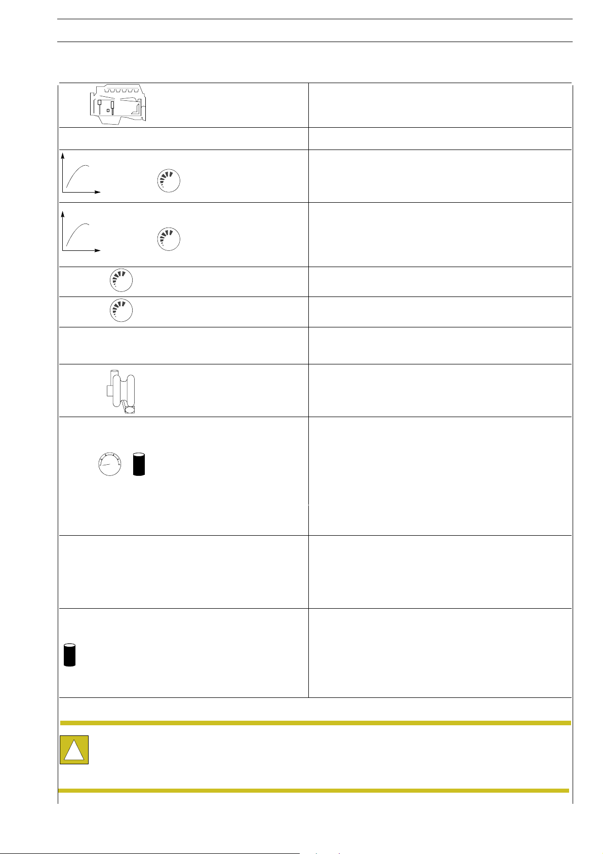
F4AE0684C*D
1
ED. FEBRUARY 2003
CLEARANCE DATA - 6 CYL.
ρ
Type
Compression ratio
Max. output kW
(HP)
rpm
Max. torque Nm
(kgm)
rpm
Loadless engine
idling rpm
Loadless engine
peak rpm rpm
Bore x stroke
Displacement
TURBOCHARGING
*
17 : 1
155
210
2300
-
-
-
-
-
102 x 120
5880
with intercooler
bar
15W40 ACEA E3
Turbocharger type
LUBRICATION
Oil pressure (warm engine)
- idling bar
- peak rpm bar 3.8
COOLING
Water pump control
Thermostat
- start of opening ºC
FILLING
engine sump liters
engine sump + filter liters
Forced by gear pump, relief valve single action
By centrifugal pump, regulating thermostat, heat
HOLSET HX35W
oil filter
1.2
exchanger, intercooler
Through belt
from 81 to 83
15
15 + 1
Data, features and performances are valid only if the technician fully complies with all the installation requirements provided
by IVECO.
!
Furthermore, the use of the unit after overhaul showd conform to the original specified power and engine rev/min for which
the engine has been designed.
Page 44
6
SECTION 3 - DUTY - INDUSTRIAL EQUIPMENT
ED. FEBRUARY 2003
NEF ENGINES
Page 45

NEF ENGINES
DIAGNOSI
ED. FEBRUARY 2003
SECTION 3 - DUTY - INDUSTRIAL EQUIPMENT
7
PART ONE - MECHANICAL COMPONENTS
Page 46

8
SECTION 3 - DUTY - INDUSTRIAL EQUIPMENT NEF ENGINES
DIAGNOSI
ED. FEBRUARY 2003
Page 47
NEF ENGINES
ENGINE OVERHAUL
ED. FEBRUARY 2003
SECTION 3 - DUTY - INDUSTRIAL EQUIPMENT
9
Preface
With regard to the engine disassembly operations
from the machine, please apply for In formation
!
consulting the specific manual.
All operations of Engine disassembly operations as
well as overhaul operations must be executed by
qualified technicians provided with the specific
tooling and equipment required.
The following information relates to the engin e overhaul
operations only for what concerns the different components
customising the engine, according to its specific duties.
In section 4, ”General overhaul”, all the operations of engine
block overhaul have been contemplated. Th erefore the above
mentioned section is to be considered as following the part
hereby described.
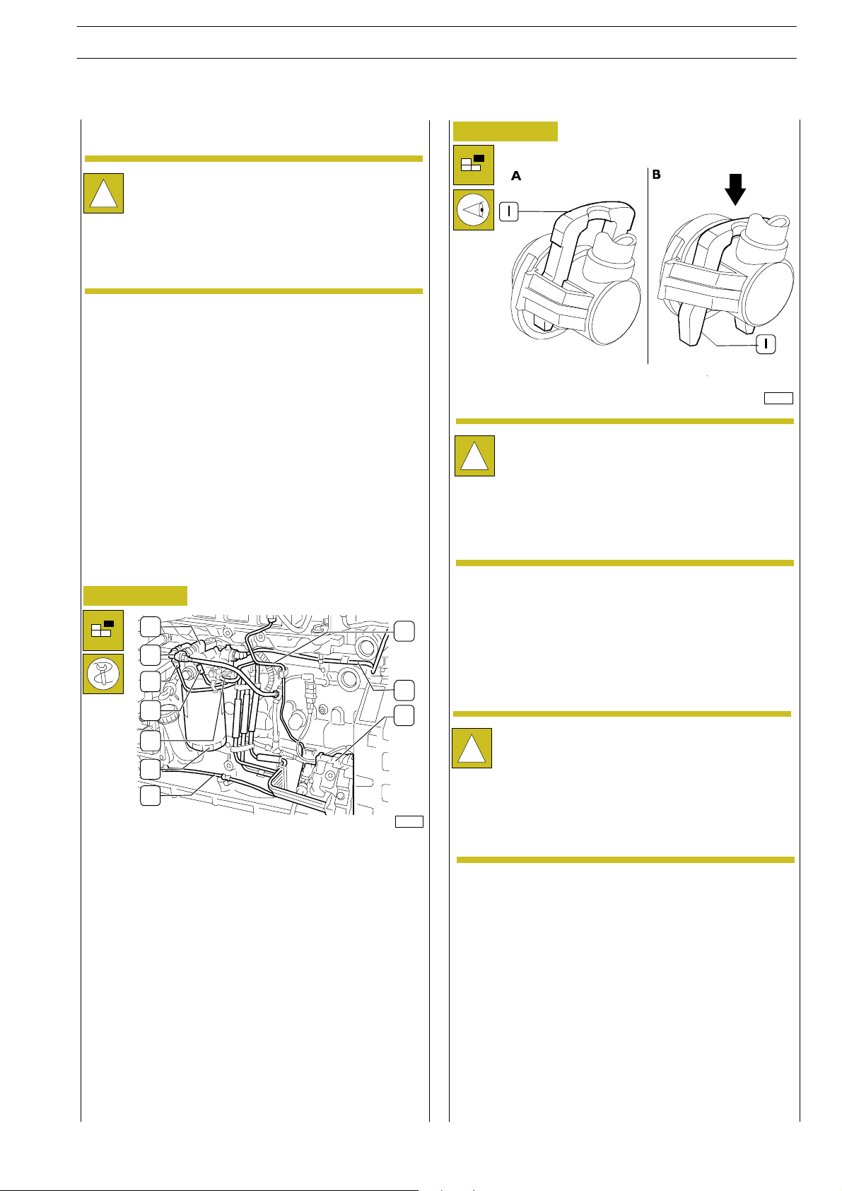
Figure 3
A Connector properly locked
B Connector released for removal-refitting
Press clamp (1), as shown in Figure B, to disconnect
the low pressure fuel pipes (3 — 4 — 5, Figure 2) from
!
the corresponding connections.
After disconnecting the pipe, reset the clamp (1) in
locking position (Figure A) to prevent distortions.
70126
Engine setting operations for the assembly on
turning stand
Figure 2
1
10
2
3
4
9
8
5
6
7
74165
In order to apply the brackets 99341009 to the engine block
to fix it on to the stand for the overh aul, it is necessary to
perform the following operations on the left hand side of the
engine:
- Using th e tool 99360073 disassembly the fuel filter (6)
and remove it from the support (1);
- Disconnect the electrical connection (2) from the
support (1) and the heater’s one (placed on the filter
support as well);
- Disconnect the fuel low pressure pipelines (3-4-5) from
the support (1);
- Disconnect pipeline (9) from the support (1);
- Remove the sustaining support bracket (1) from the
block.
Disconnect the high pressure fuel pipeline (10, Figure 2) from
the rail diffuser and from the high pressure pump (8) and
disassemble it from the engine block removing the fixing
clamps.
Disconnect the pipeline (7) feeding the mechanic pump that
is combined to the high pressure pump through the exchanger
of the engine control module.
Because of the high pressure in the pipelines running
from the high pressure pump to the rail and from this
!
last one to the electro-injectors, it is absolutely
required NOT to:
- disconnect the pipelines when the engine is
working;
- re-use the disassembled pipelines.
Page 48
10
SECTION 3 - DUTY - INDUSTRIAL EQUIPMENT NEF ENGINES
ED. FEBRUARY 2003
Ontherighthand side ofthe engine:
Figure 4
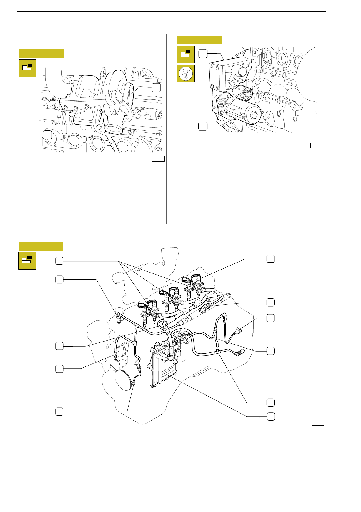
1
74167
Remove the screws and remove the oil pipe (1) from the
turbocharger pipe (2) and from the engine block.
Figure 5
1
2
2
74166
Disconnect the oil feed pipeline unlocking the three screws
M12x25. Remove the O-ring from the pipe.
Remove the starter (2) from the flywheel housing (1).
Apply brackets 99361037 to engine block and use t hem to
secure the engine to the revolving stand 99322205. Remove
sump cap and drain out oil.
Remove the fan from the output shaft pulley.
Disassembly of application components
Figure 6
1
2
3
4
5
6
7
8
9
10
11
74168
1. Connections for Electro-injectors - 2. Engine cooling liquid temperature’s sensor - 2. Cable of the fuel pressure sensor - 4.
Sensor of engine’s o il temperature and pressure - 5. Driving shaft sensor - 6. El ectro-injector - 7. Temperature - air pressure
sensor - 8. Timing system sensor - 9. Cable of fuel heater and fuel temperature’s sensor - 10. Cable of pressure regulating
gauge - 11. EDC 7 gearbox.
Page 49
NEF ENGINES
ED. FEBRUARY 2003
SECTION 3 - DUTY - INDUSTRIAL EQUIPMENT
11
Disconnect the engine’s cable from the connectors (1.
Figure 6) wirin g harness to
Electro-injectors (6); (7) air pressure/temperature sensor;(3)
fuel pressure sensor;
(11) engine control module; (10) high pressure pump sensor;
(8) timing system sensor; (2) Thermostat sensor of engine
cooling liquid’s temperature; (5) sensor of engine’s
revolutions.
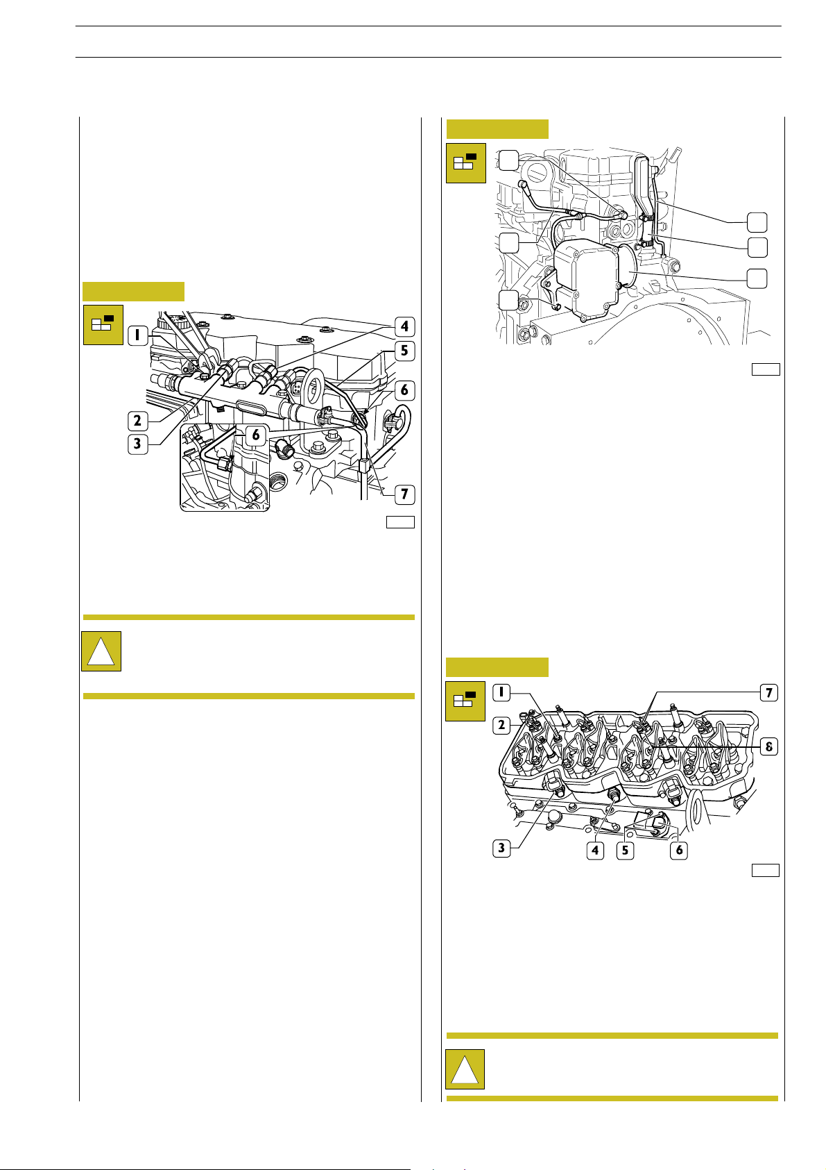
Figure 7
70236
Disconnect from the rail (2): the fuel pipe (7) according to
procedures described in figure 3. Disconnect fuel pipes (5)
from rail (2) and injector manifolds (6).
Figure 8
1
6
2
5
4
3
74170
Disconnectthepipeline(2)fromthefuelrecover
pressure-limiter, working on the connections as described in
Figure 3.
Unscrew the nut and loosen the clamp tightening the oil
vapour pipe.
Removethepipe(6).
Loosen the screws (3) and disassemble the blow-by filter (4).
Remove on the nuts and tappet cover.
When releasing pipe (6) c o nnections (4) to rail (2),
use the proper wrench to avoid rotation of flow
!
limiters (3).
Remove the screws (1) and disconnect the rail (2).
Figure 9
70131
Remove nuts (7) and disconnect the electrical cables from
injectors (8).
Remove screws (1) and disconnect injec tor wiring support
(2) including the gasket.
Remove screws (5), disconnect air pressure/temperature
sensor (6).
Remove nuts (3) and remove fuel manifolds (4).
Disassembled fuel manifolds (4) must not be used
again, replace with new ones during reassembly.
!
Page 50
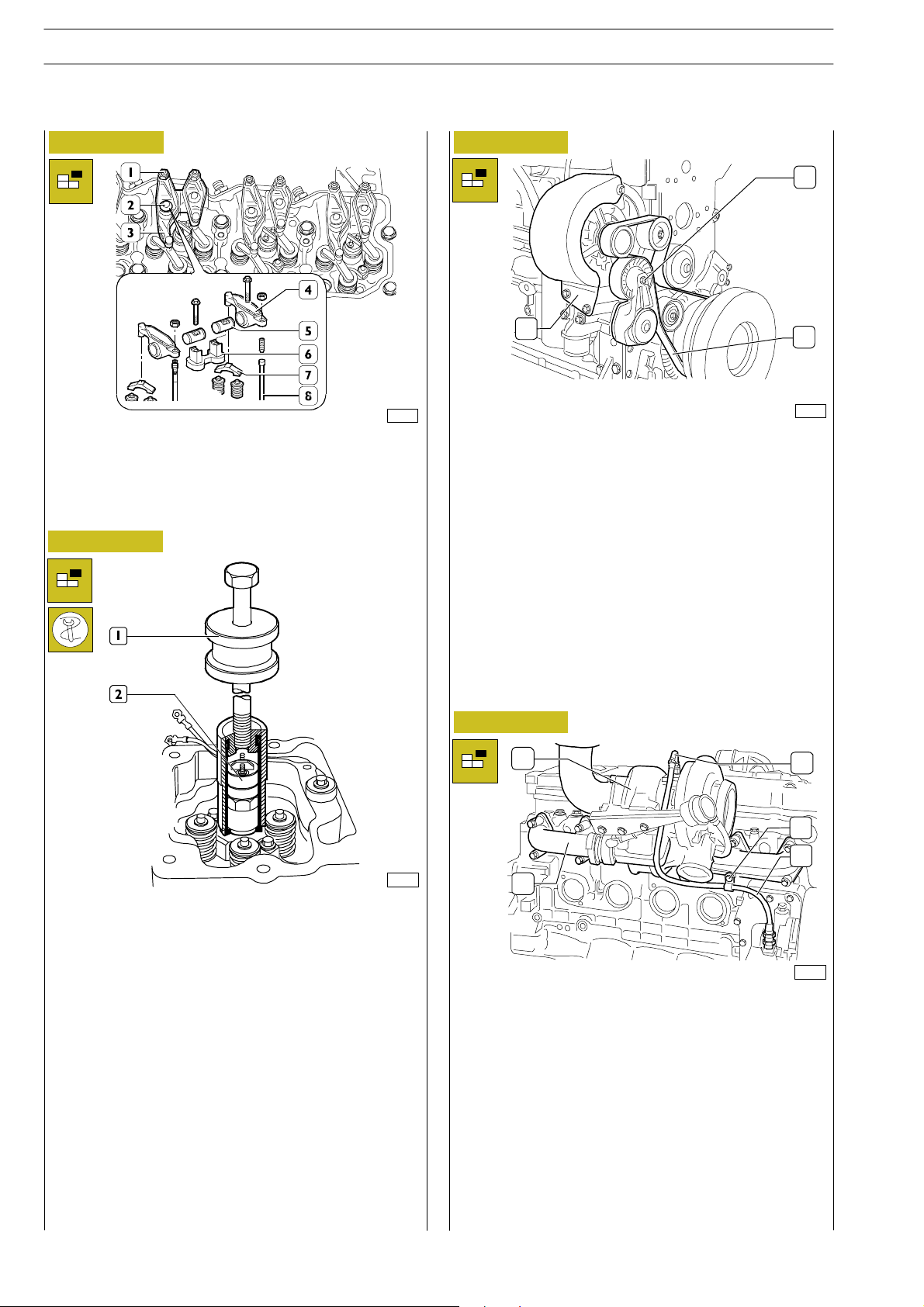
12
SECTION 3 - DUTY - INDUSTRIAL EQUIPMENT NEF ENGINES
ED. FEBRUARY 2003
Figure 10
70132
Loosen tappet adjustment fastening nuts (1) and unscrew the
adjusters.
Remove the screws (2), remove the rocker assembly (3),
consisting of: bracket (6), rockers (4), shafts (5) and remove
jumpers (7) from valves.
Remove rods (8).
Figure 11
Figure 12
1
2
Loosen the screws fixing the alternator’s protection to the
support and remove it;
Release on the drive belt tensioner (1) and extract the belt
(3) from the belt pulleys from the water pump ones and from
the belt rebound pulleys;
Disassemble th e belt tensioner;
Loosen the screws fixing the alternator to the support and
disassemble it.
3
74171
70133
Remove injector fastening screws. Use tool 99342101 (1) to
remove injectors (2) from the cylinder head.
Figure 13
1
5
4
3
2
74172
Remove the screw (4) holding th e fixing clamp of the
turbocharger’s lubricating oil pipeline.
Disconnect the oil pipeline (3) from the supports of the heat
exchanger / oil filter and from the pipe fitting (5) to the
turbine.
Remove the fixing nuts and disassemble the turbocharger (1)
from the exhaust collector (2).
Loosen the screws and disassemble the exhaust collector (2)
from the cylinder head.
Page 51
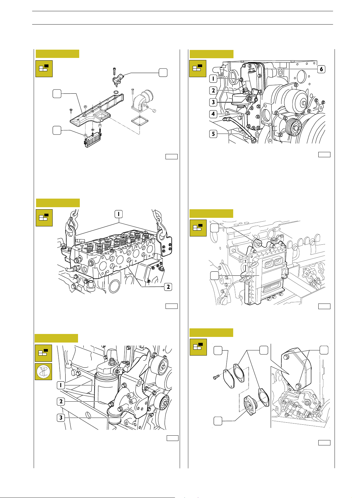
NEF ENGINES
ED. FEBRUARY 2003
SECTION 3 - DUTY - INDUSTRIAL EQUIPMENT
13
Figure 14
3
1
2
74173
On the opposite side, loosen the fixing screws of the inlet
manifold (1) and disassemble the joint to the air heater (2)
for the cold start.
Figure 15
Figure 17
70141
Remove the screws (4) and disconnect the oil
temperature/pressure sensor (3).
Remove the screws (1) and then remove: heat exchanger/oil
filter support (2), intermediate plate (6) and relevant gaskets.
Remove the oil level sensor (5).
Figure 18
70137
Hook brackets (1) with suitable lifting chains and remove
cylinder head (2) from block using hoist.
Figure 16
1
2
74174
Removethe screws (1) and disconnect the ECU (2) including
the heat exchanger.
Figure 19
1
34
70140
Remove the screws (2) and disconnect the alternator
support (3).
Use tool 99360076 to remove the oil filter (1).
2
74176
Unloose the screws (3) and remove the cap (1). Keep the
gasket (4), the power take-off (2) and the second gasket (4).
Page 52
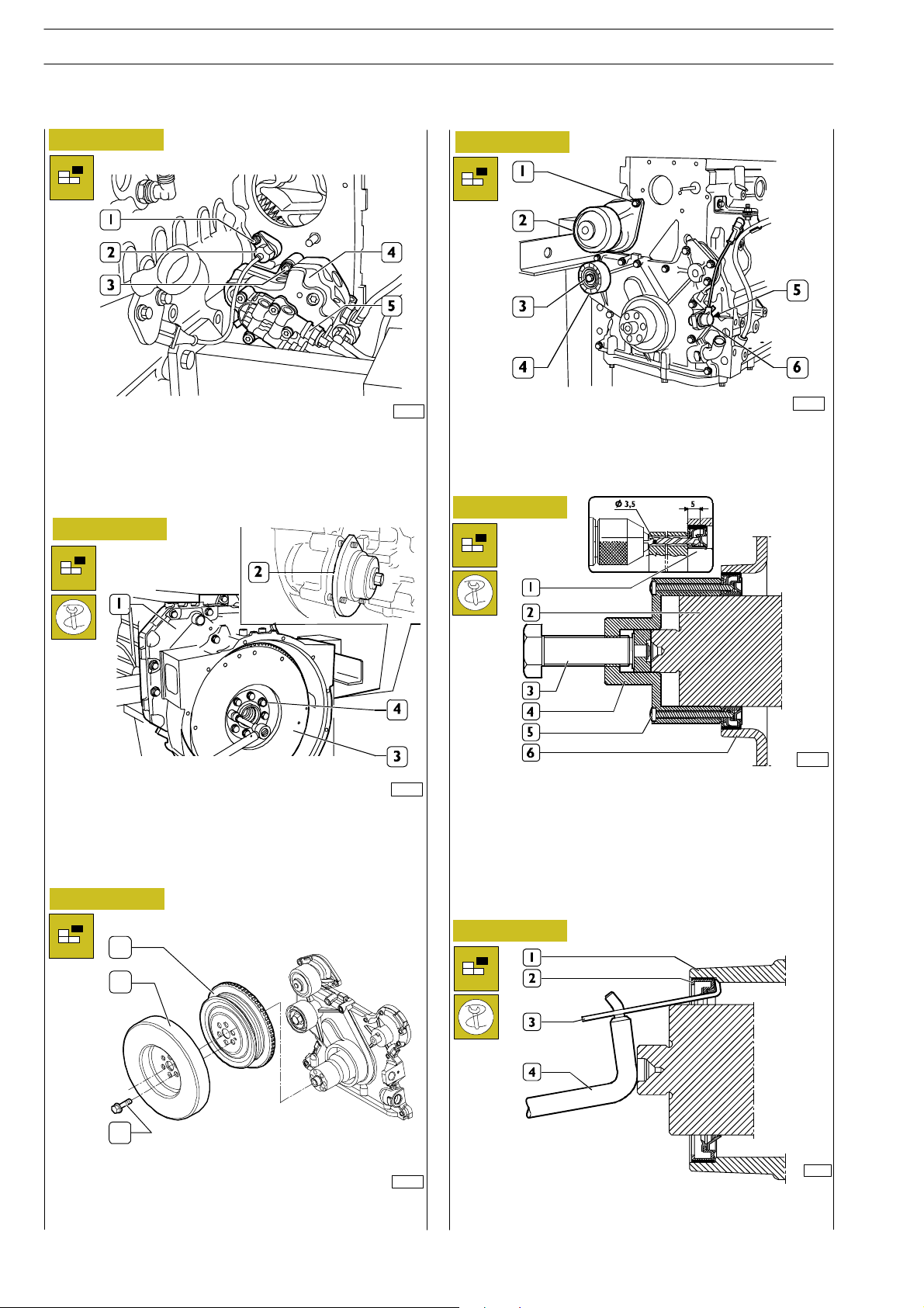
14
SECTION 3 - DUTY - INDUSTRIAL EQUIPMENT NEF ENGINES
ED. FEBRUARY 2003
Figure 20
70145
Remove the nut (1) and disconnect the timing sensor (2).
Remove the nuts (3) and disconnect the high pressure pump
(4) including the feed pump (5).
Figure 21
Figure 23
70148
Remove the screws (1) and disconnect the water pump (2).
Remove the screw (3) and the roller (4).
Remove the screw (5) and disconnect the engine speed
sensor (6).
Figure 24
70146
Fit tool 99360339 (2) to the flywheel housing (1) to stop
flywheel (3) rotation.
Loosen the screws (4).
Figure 22
1
2
3
74175
Remove the s crews (3) and disassemble the damping flywheel
(2) and the pulley (1).
00900t
Remove the ring sealing the en gine’s driving shaft from the
front cover. Use the tool 99340055 (4) to operate on the front
bar hold of the driving shaft. Through the steering holes of the
tool, perforate the inside holding ring (1) with a straight wa y
drill (diam. 3,5mm) for the depth of 5mm. Fix the tool to the
ring tightening the 6 screws provided with the equipment.
Then proceed removing the ring (2) by tightening the screw
(3).
Figure 25
00904t
Using the specific tie rod (3) of the tool 99363204 and the
ancillary lever (4), remove t he external holding ring (2) from
the front cover (1).
Page 53
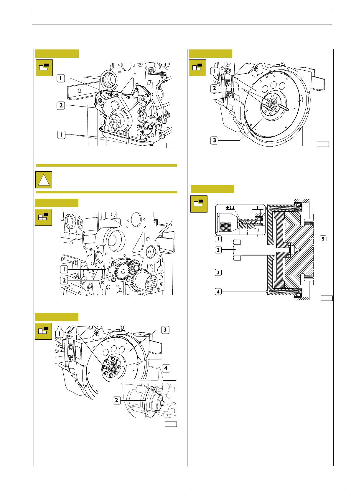
NEF ENGINES
ED. FEBRUARY 2003
SECTION 3 - DUTY - INDUSTRIAL EQUIPMENT
15
Figure 26
Remove the sc rews (1) and take out the front cover (2).
Take note of screw (1) assembling positions since
they have different lengths.
!
Figure 27
70149
Figure 29
70152
Tighten two screws of medium length into the holes (4) to
sling the flywheel with the hoist.
Throughout the two guide pins (2) previously screw into the
driving shaft h o les (3) withdraw th e engine flywheel (1) after
slinging it with the hoist.
Figure 30
Remove the screws (1) and disconnect the oil p ump (2).
Figure 28
70151
Remove two opposite screws (1) from the area where the
withdrawal pins will be introduced (2, Picture 29).
Loosen the remaining flywheel fixing screws (3) from the
driving shaft (4).
Remove the flywheel locking tool.
00903t
Remove the holding ring of the flywheel cover box using the
tool 99340056 (3) to operate on the driving shaft’s back bar
hold (5).
Through the steering holes of the tool, perforate the inside
holding ring with a straight way drill (diam. 3,5mm) for the
depth of 5mm.
Fix the tool 99340056 (3) to the ring tightening the 6 screws
provided with the equipment.(4)
Then proceed removing the ring (1) by tightening the screw
(2).
Using a specific tie rod of the tool 99363204 and an ancillary
lever, remove the external holding ring (2) from the front
cover.
Page 54
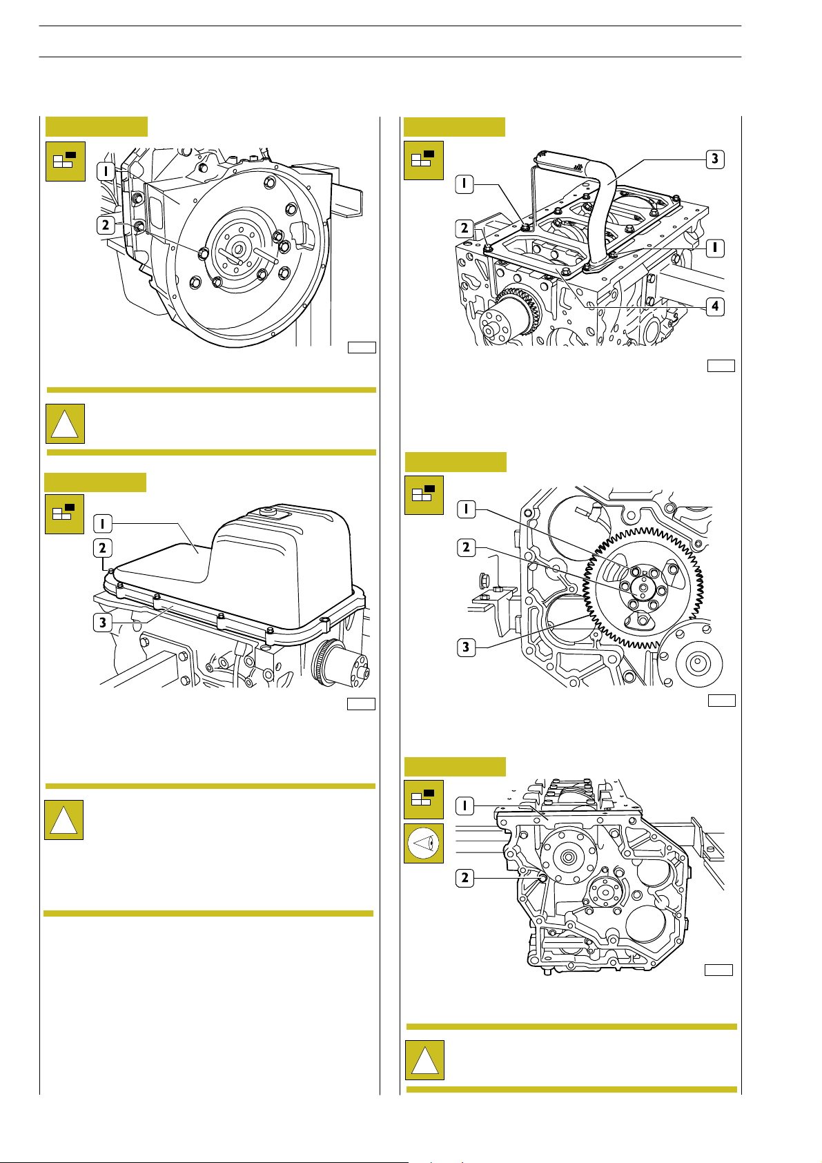
16
SECTION 3 - DUTY - INDUSTRIAL EQUIPMENT NEF ENGINES
ED. FEBRUARY 2003
Figure 31
Remove the screws (2) and take out the rear cover (1).
Take note of screw (2) assembling positions since
they have different sizes.
!
Figure 32
Figure 33
70153
70155
Remove the screws (1) and disassemble the oil suction tube
(3).
Remove the screws (2) and disassemble the stiffening plate
(4).
Figure 34
70154
Overturn the engine.
Remove the screws (2), disassemble the plate (3) and
disconnect the oil sump (1).
The shape and the dimensions of the oil pan and of
the suction tube may vary according to the duty of
!
the engine. The relevant pictures of the instructions
are therefore providing an outline of the
intervention to be executed.
However the procedures described are still
applicable.
70156
Remove the screws (1) and remove the gear (3) from the
camshaft (2).
Figure 35
70157
Remove the screws (2) and disconnect the timing gear case
(1).
Take note of screw (2) assembling positions since
they have different sizes.
!
Page 55
NEF ENGINES
ED. FEBRUARY 2003
SECTION 3 - DUTY - INDUSTRIAL EQUIPMENT
17
Assembly of application components
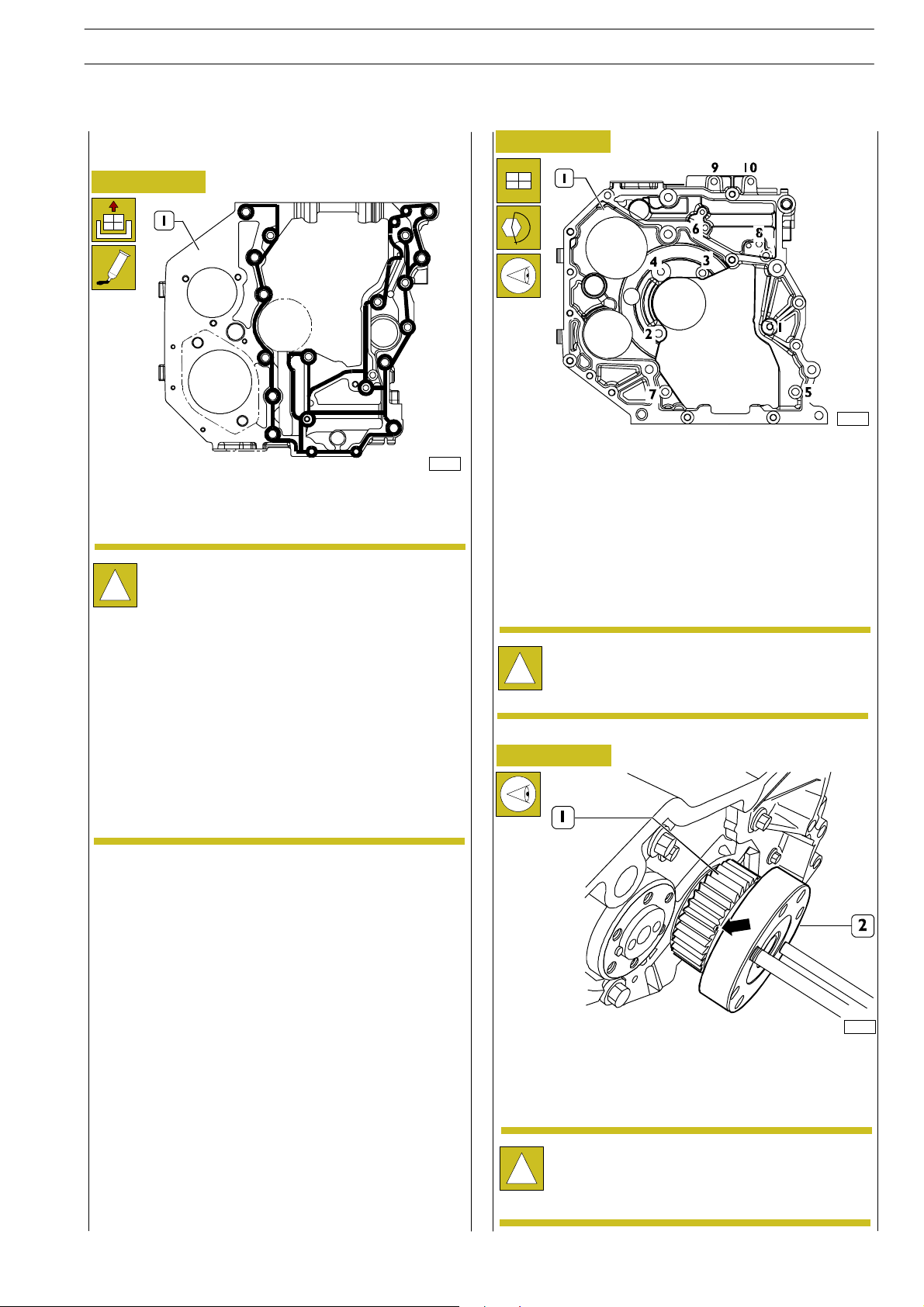
Figure 36
70209
LOCTITE 5205 SEALANT APPLICATION AREAS
Clean accurately the timing gear case (1) and the engine
block.
Perfect seal is only obtained by cleaning accu rately the
surface to seal.
!
Smear the case with LOCTITE 5205 to obtain a bead
of few mm diameter.
It shall be uniform (no clots), without air bubbles, thin
areas or discontinuities.
Any imperfection shall be corrected as soon as
possible.
Avoid to use excess material to seal the joint.
Excessive sealant could come out from joint sides and
cause lubricant passage clogging.
After applying the sealant, th e join t shall be assembled
immediately(10—20minutes).
Figure 37
70210
DIAGRAM FOR TIGHTENING THE REAR TIMING
GEAR CASE FASTENING SCREWS
Refit the case (1) to the engine block.
Screw the fastening screws in the same position found at
removal and tighten them to the following torque values in
the sequence shown in the figure:
ScrewsM12 65to89Nm
Screws M8 20 to 28 Nm
ScrewsM10 42to52Nm
Before any assembly operation always verify that the
hole and screw threads have no evidence of wear or
!
dirt.
Figure 38
70211
Use a felt pen to mark the driving gear (1) tooth fitted on the
output shaft (2) having the mark (→) for timing on the side
surface.
Fasten screwing of the two pins to facilitate the
operation of engine driving shaft rotation.
!
Page 56
18
SECTION 3 - DUTY - INDUSTRIAL EQUIPMENT NEF ENGINES
ED. FEBRUARY 2003
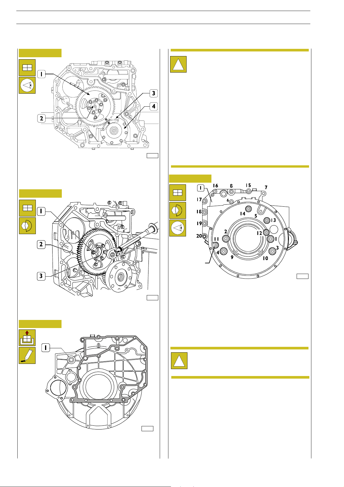
Figure 39
70212
Rotate the output shaft (4) and the camshaft (2) so that when
fitting the driven gear (1) on the camshaft the marks on the
gears (1 and 3) are coinciding.
Figure 40
Perfect seal is only obtained by cleaning accu rately the
surface to seal.
!
Smear the case with LOCTITE 5205 to obtain a bead
of few mm diameter.
It shall be uniform (no clots), without air bubbles, thin
areas or discontinuities.
Any imperfection shall be corrected as soon as
possible.
Avoid to use excess material to seal the joint.
Excessive sealant could come out from joint sides and
cause lubricant passage clogging.
After applying the sealant, th e join t shall be assembled
immediately(10—20minutes).
Figure 42
70213
Tighten the screws (1) fastening gear (2) to camshaft (3) to
the specified torque.
Figure 41
Not available
On engines
F4AE0684H-E
70215
SEQUENCE FOR TIGHTENING THE FLYWHEEL
HOUSING FASTENING SCREWS
Refit the housing (1) to the engine block and screw the
fastening screws in the same position found at removal and
tighten them to the following torque values in the sequence
showninthefigure:
ScrewsM12 75to95Nm
ScrewsM10 44to53Nm
Before any assembly operation always verify that the
hole and screw threads have no evidence of wear or
!
dirt.
LOCTITE 5205 SEALANT APPLICATION AREAS
70214
Page 57
NEF ENGINES
ED. FEBRUARY 2003
SECTION 3 - DUTY - INDUSTRIAL EQUIPMENT
19
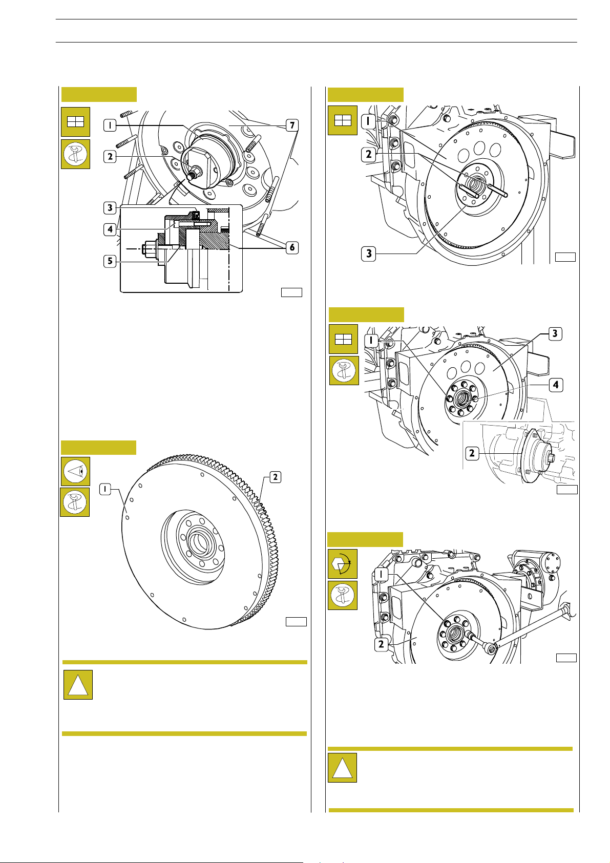
Figure 43
00901t
Apply tool 99346252 part (6) to the rear output shaft tang
(5), secure it by screws (4) and fit the new sealing ring (3).
Position part (1) on part (5), screw nut (2) until completing
sealing ring (3) fitting into fly w heel housing (7).
Figure 45
70152
Screw two pins (2) having suitable length into shaft holes (3)
and remove the engine flywheel (1) using proper sling and
hoister.
Figure 46
Figure 44
Where the engine is coupled to a mechanical clutch,
verify that the flywheel nominal thickness of 49,6 ±
!
0,13 mm.
70217
70151
Apply tool 99360339 (2) to the flywheel housing to stop
engine flywheel (3) rotation. Tighten the screws (1) fastening
the engine flywheel (3) to the output shaft.
Figure 47
α
70219
Tighten engine flywheel (2) fastening screws (1) in two
stages:
st
- 1
- 2
stage, tightening to 30 ± 4Nmtorquewith
dynamometric wrench;
nd
stage, tightening to 60°±5° angle.
Check ring gear teeth (2), if breakage or excessive wear is
found remove the ring gear from the engine flywheel (1,
Figure 43) using a suitable hammer and fit the new one,
previously heated to 150°C for 15 to 20 minutes. Chamfering
on ring gear inside diameter shall be facing the engine
flywheel.
Tightening to angle is performed using tool
99395216.
!
Before any assembly operation always verify that the
hole and screw threads have no evidence of wear or
dirt.
Page 58
20
SECTION 3 - DUTY - INDUSTRIAL EQUIPMENT NEF ENGINES
ED. FEBRUARY 2003
Figure 48
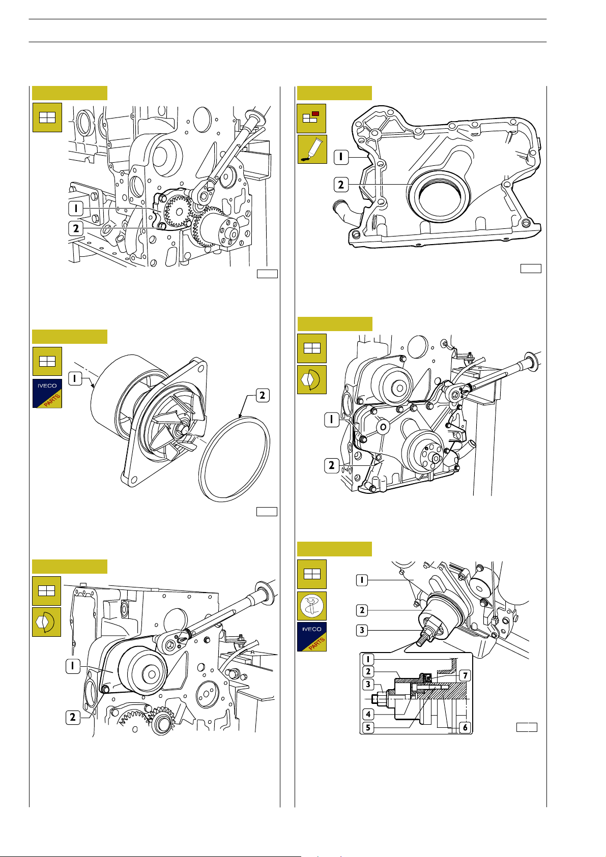
Fit the oil pump (1).
Tighten the fastening screws (2) to the specified torque.
Figure 49
70220
Figure 51
70223
Remove the sealing ring (2) from the front cover (1), clean
accurately the coupling surfaces and smear them with
LOCTITE 5205.
Figure 52
Apply a new sealing ring (2) to the water pump (1).
Figure 50
Fit the water pump (1).
Tighten th e screws (2) to the specified torque.
70221
Clean accurat ely the front cover (2) surface and refit it.
Tighten th e screws (1) to the specified torque.
Figure 53
00902t
Apply tool 99346252 part (4) to the front output shaft tang
(6), secure it by screws (5) and fit the new sealing ring (7).
Position part (2) on part (4), screw nut (3) until completing
sealing ring (7) fitting into fron t cover (1).
Page 59
NEF ENGINES
ED. FEBRUARY 2003
SECTION 3 - DUTY - INDUSTRIAL EQUIPMENT
21
Figure 54
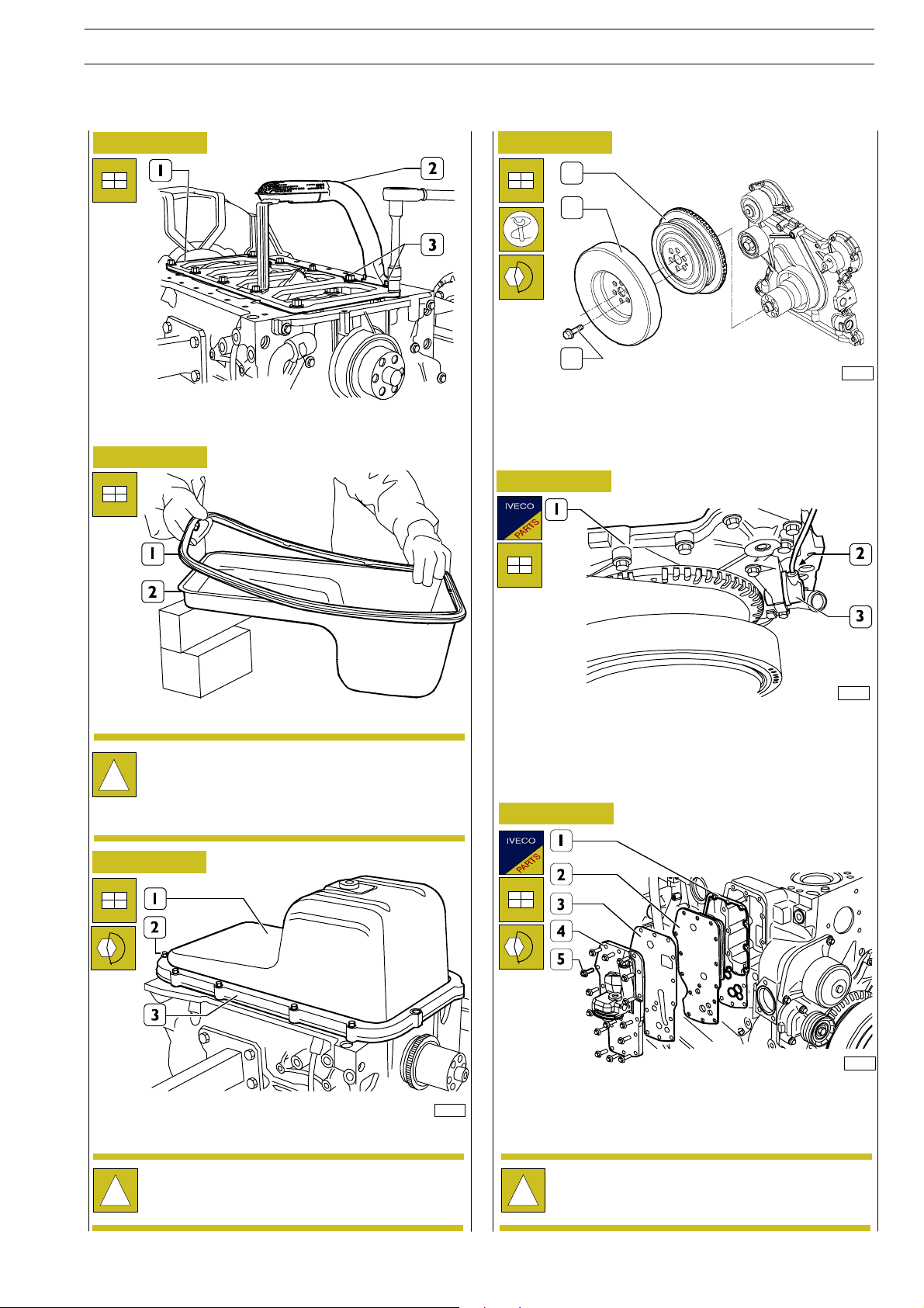
Fit the plate (1), the oil pick up tube (2) and tighten the
fastening screws (3) to the specified torque.
Figure 55
Figure 57
1
2
3
Assemble the pulley (1) and the damping flywheel (2) to t he
driving shaft.
Tighten the fixing screws (3) and clamp them to the couple 68
± 7 Nm.
Figure 58
74175
Set the gasket (1) on the oil sump (2).
The pictures of the in structions relating to the oil pan
and to thesuction rose may not reflect the actual
!
shape and dimensions of your engine equipment.
However the procedures described are still
applicable.
Figure 56
Fit the oil sump (1) and apply the plate (3) to it.
Tighten th e screws (2) to the specified torque.
70154
70230
Fit a new sealing ring on the speed sensor (3).
Fit the speed sensor (3) on the front cover (1) and tighten
the screw (2) to the specified torque.
Figure 59
70231
Fit on the engine block: a new gasket (1), the heat exchanger
(2) a new gasket (3) and th e oil filter support (4).
Tighten th e screws (5) to the specified torque.
Before any assembly operation always verify that the
hole and screw threads have no evidence of wear or
!
dirt.
Before any assembly operation always verify that the
hole and screw threads have no evidence of wear or
!
dirt.
Page 60
22
SECTION 3 - DUTY - INDUSTRIAL EQUIPMENT NEF ENGINES
ED. FEBRUARY 2003
Figure 60
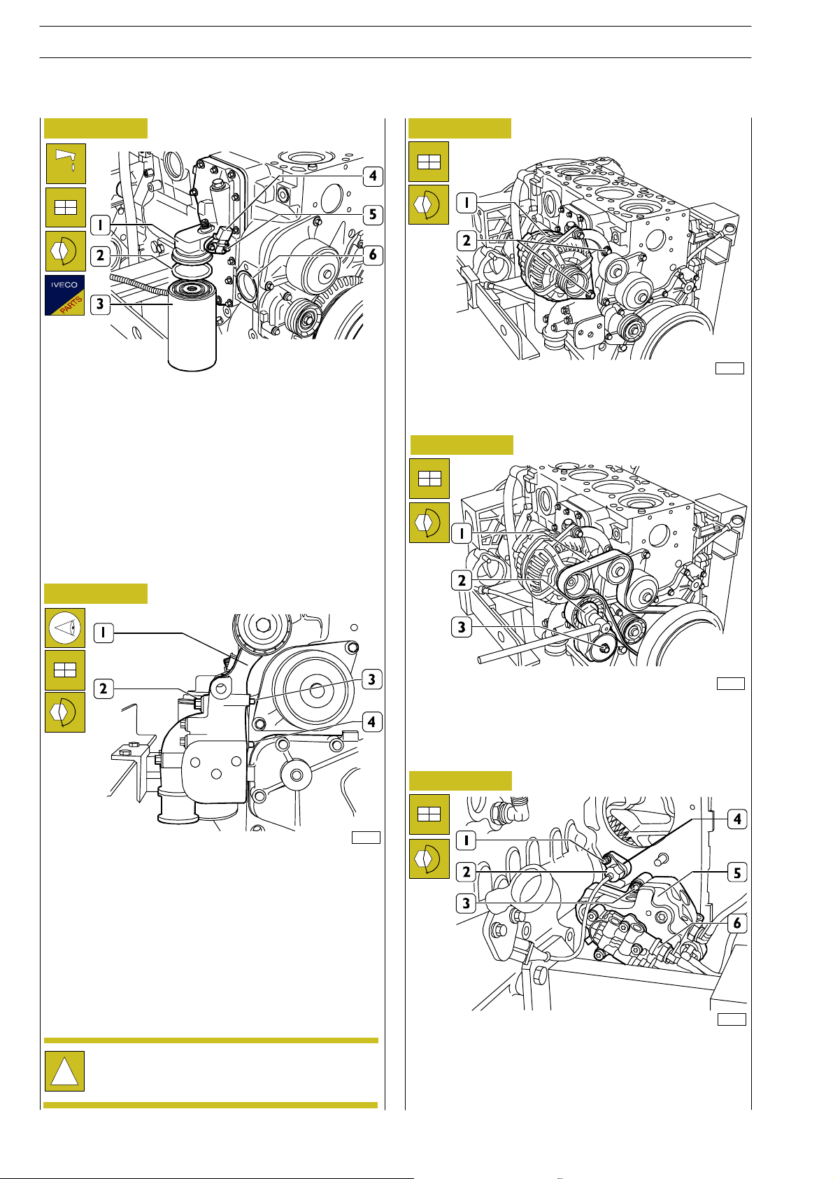
Lubricate the sealing ring (2) with engine oil and set it on the
oil filter (3).
Screw manually to seat the oil filter (3) o n the support
connection (1) and then screw again the oil filter (3) by ¾
turn.
Apply a new sealing ring on the oil temperature/pressure
sensor (4) and fit it on the support (1).
Tighten th e screws (5) to the specified torque.
Fit a new sealing ring (6) in the engin e block seat.
Figure 62
74177
Refit the alternator (1).
Tighten the screw (2) to the specified torque.
Figure 63
Figure 61
70234
Position the alternator support (1) so that pins (3 and 4) are
set against the engine block.
Tighten th e screws (2) to the specified torque.
74178
Refit the automatic belt tensioner (2).
Tighten the screw (3) to the specified torque using a wrench,
turn the automatic belt tensioner (2) to fit the belt (1) on
pulleys and guide rollers.
Figure 64
Before any assembly operation always verify that the
hole and screw threads have no evidence of wear or
!
dirt.
70145
Refit the high pressure pump (6) including the feed pump (5)
and tighten the nuts (3) to the specified torque. Fit the
support (4) w ith a new sealing ring, the timing sensor (2) with
a new sealing ring and tighten the relevant fastening nut (1)
to the specified torque.
Page 61
NEF ENGINES
ED. FEBRUARY 2003
SECTION 3 - DUTY - INDUSTRIAL EQUIPMENT
23
Figure 66
1
4
3
2
74176
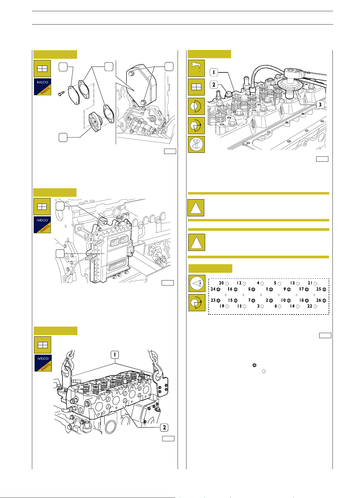
Insert the power take-off (2) equipped with the gasket (4), the
cover (I) and its gasket (4).
Tighten the screws (3) to the prescribed matching couple.
Figure 67
1
Figure 69
α
70336
Assemble cylinder head (1), tigh t en the screws (2) in three
following steps, following order and mode shown in the
figure below.
The angle tightening is carried out through tool
99395216 (3).
!
2
74174
Assemble the electronic gearbox (2) equipped with the
exchanger to the engine, fixing it with the screws (1).
In case the rubber buffers are cracked or excessively deformed,
provide replacing them.
Figure 68
Before any assembly operation always verify that the
hole and screw threads have no evidence of wear or
!
dirt.
Figure 65
α
6-cylinder engine
70476
Tightening order layout for cylinder head fastening screws:
st
- 1
step pre-tightening with a torque wrench:
• Screw 12x1.75x130 ( ) 35 ± 5Nm
A • Screw 12x1.75 x 150 ( ) 55 ± 5Nm
nd
- 2
- 3
step tightening with a 90°±5° angle
rd
step tightening with a 90°±5° angle
A=Frontside
A
70137
Apply a new gasket to the engine block and then place the
cylinder head (2) slung by the hanger brackets (1).
Page 62
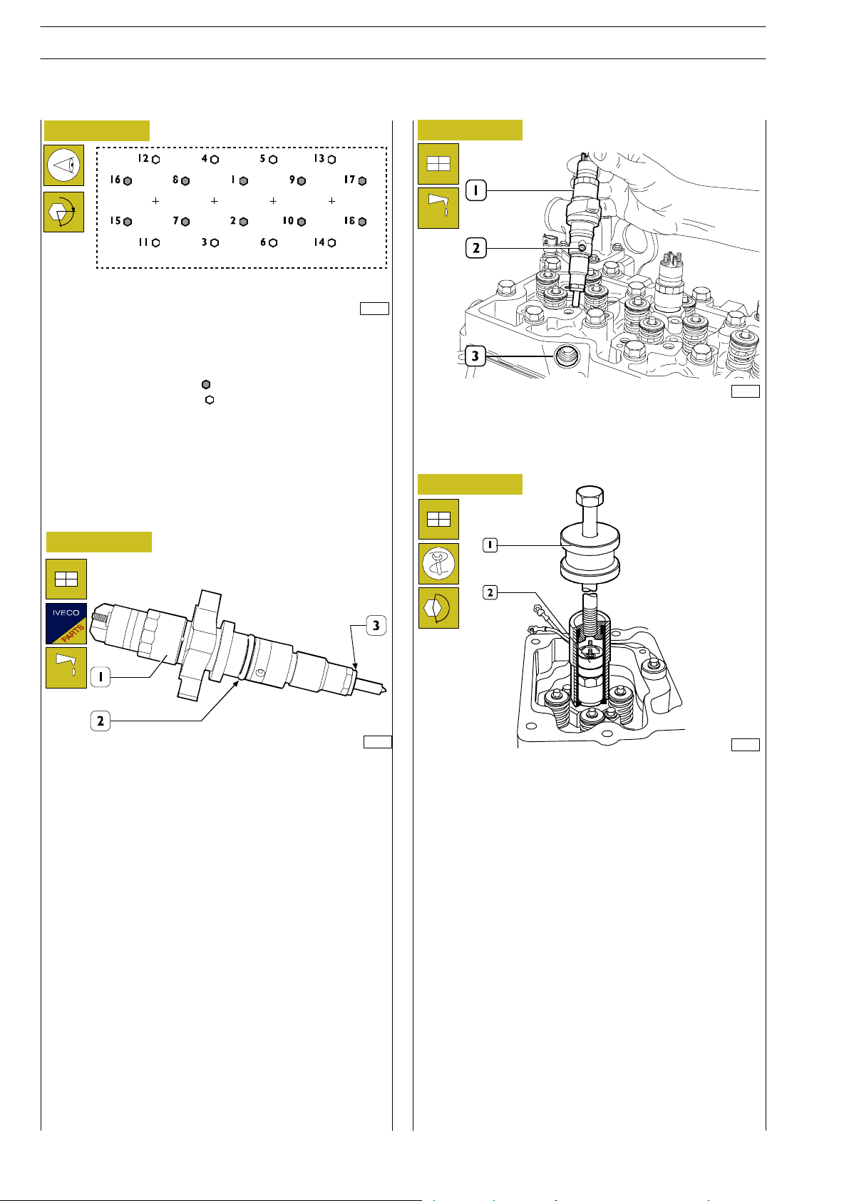
24
SECTION 3 - DUTY - INDUSTRIAL EQUIPMENT NEF ENGINES
ED. FEBRUARY 2003
Figure 70
α
4-cylinder engine
Cylinder head fastening screws tightening sequence:
st
stage pre-tightening, with a torque wrench:
- 1
• Screw 12x1.75x130 ( ) 35 ± 5Nm
• Screw12x1.75 x 150 ( ) 55 ± 5Nm
A=Frontside
nd
- 2
- 3
stage tightening with angle 90°±5°
rd
stage tightening with angle 90°±5°
Figure 71
Figure 72
A
70337
70339
Fit injectors (1) on the cylinder head seats, directed so that
the fuel inlet hole (2) is facing the fuel manifold seat (3) side.
Figure 73
70338
Fit a new sealing ring (2) lubricated with petroleum jelly and
a new sealing washer (3) on inject or (1).
70133
Use tool 99342101 (1) to fit the injector (2) into its seat.
Screw injector fastening screws without tightening them.
Page 63
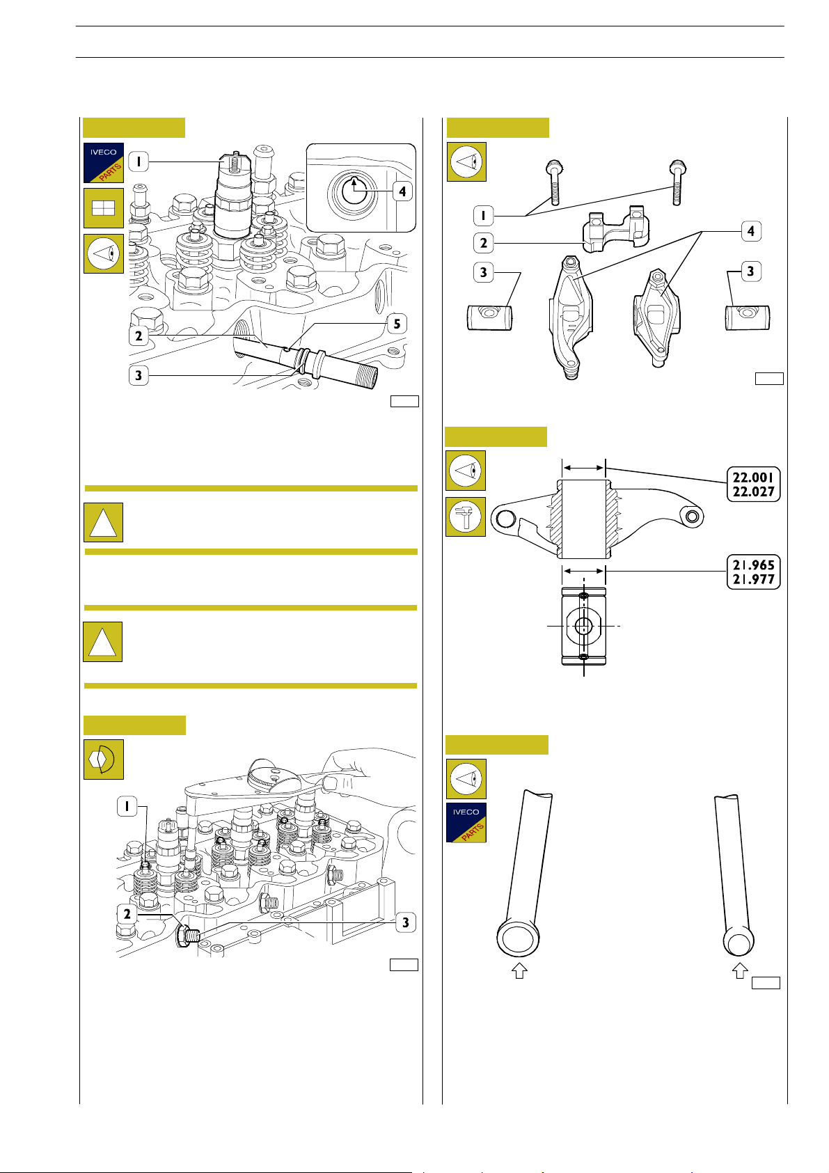
NEF ENGINES
ED. FEBRUARY 2003
SECTION 3 - DUTY - INDUSTRIAL EQUIPMENT
25
Figure 74
70341
Fit a new sealing ring (3) lubricated with petroleum jelly on
the fuel manifold (2) and fit it in to the cylin der head seat so
that the positioning ball (5) is coinciding with the relevant
housing (4).
Disassembled fuel manifolds (2) must not be used
again. Replace with new items.
!
Figure 76
70343
ROCKER ASSEMBLY COMPONENTS:
1. Screws - 2. Bracket - 3. S hafts - 4. Rockers.
Figure 77
Screw the fastening nuts (2, Figure 75) without locking them.
During this operation, the injector (1) shall be
moved so that the manifold (2) is properly inserted
!
into the fuel inlet hole (2, Figure 72).
Figure 75
70342
Use the torque wrench to tighten gradually and alternately
the injector fastening screws (1) to 8.5 ± 0.8 Nm torque.
Tighten the fuel manifold (3) fastening nuts (2) to 50 Nm
torque.
Carry out the assembly of the equalisers’ unit , after previous
check of the components.
SHAFT-ROCKER MAIN DATA
Check that shaft/rocker coupling surfaces are not showing
excessive wear or damages.
Figure 78
32655
Rocker control rods shall not be distorted; the ball seats in
touch with the rocker adjusting screw and with tappets
(arrows) shall not show seizing or wear; otherwise replace
them. Intake and exhaust valve control rods are identical and
are therefore interchangeable.
Page 64
26
SECTION 3 - DUTY - INDUSTRIAL EQUIPMENT NEF ENGINES
ED. FEBRUARY 2003
Figure 79
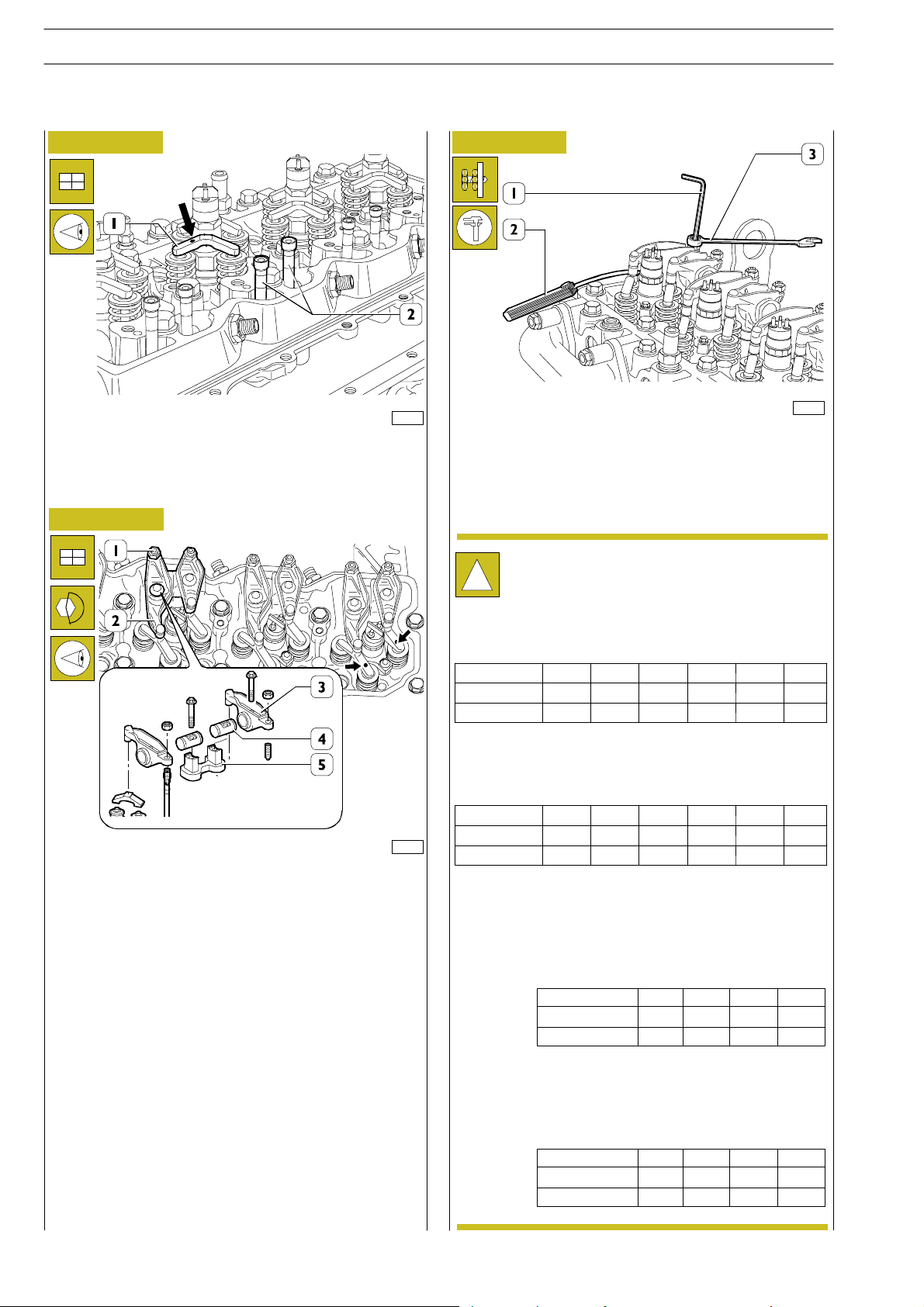
70345
Fit the rods (2).
Position jumpers (1) on valves with marks (→)facingthe
exhaust manifold.
Figure 80
Figure 81
70520
Adjust clearance between rockers and valves using setscrew
wrench (1), box wrench (3) and feeler gauge (2).
Working clearance shall be as follows:
- intake valves 0.25 ± 0.05 mm
- exhaust valves 0.51 ± 0.05 mm.
In order to more quickly perform the operating
clearance adjustment for rocker arms — valves,
!
proceed as follows:
rotate the drive shaft, balanc e cylinder 1 valves and
adjust th e valves marked by the asterisk as shown in
the table:
cylinder n. 1 2 3 4 5 6
intake - - * - * *
exhaust - * - * - *
70346
Check that tappet adjusters (1) are loose to prevent their
balking on the rods (2, Figure 79) when refitting the rocker
assembly.
Then refit the rocker assembly consisting of: bracket (5),
rockers (3), shafts (4) and secure them to the cylinder head
by tightening the fastening screws (2) to 36 Nm torque.
Rotate the drive shaft, balance cylinder 6 valves and
adjust th e valves marked by the asterisk as shown in
the table:
cylinder n. 1 2 3 4 5 6
intake * * - * - exhaust * - * - * -
Engine with 4 cylinder: rotate the drive shaft, balance
cylinder 1 valves and adjust the valves marked by the
asterisk as shown in the table:
cylinder n.
intake
exhaust
1
-
-
234
*
**
--
Rotate the drive shaft, balance cylinder 4 valves and
adjust th e valves marked by the asterisk as shown in
the table:
cylinder n.
intake
exhaust
1
234
-
*
**
*
-
*
-
-
Page 65
NEF ENGINES
ED. FEBRUARY 2003
SECTION 3 - DUTY - INDUSTRIAL EQUIPMENT
27
Figure 82
3
1
2
74173
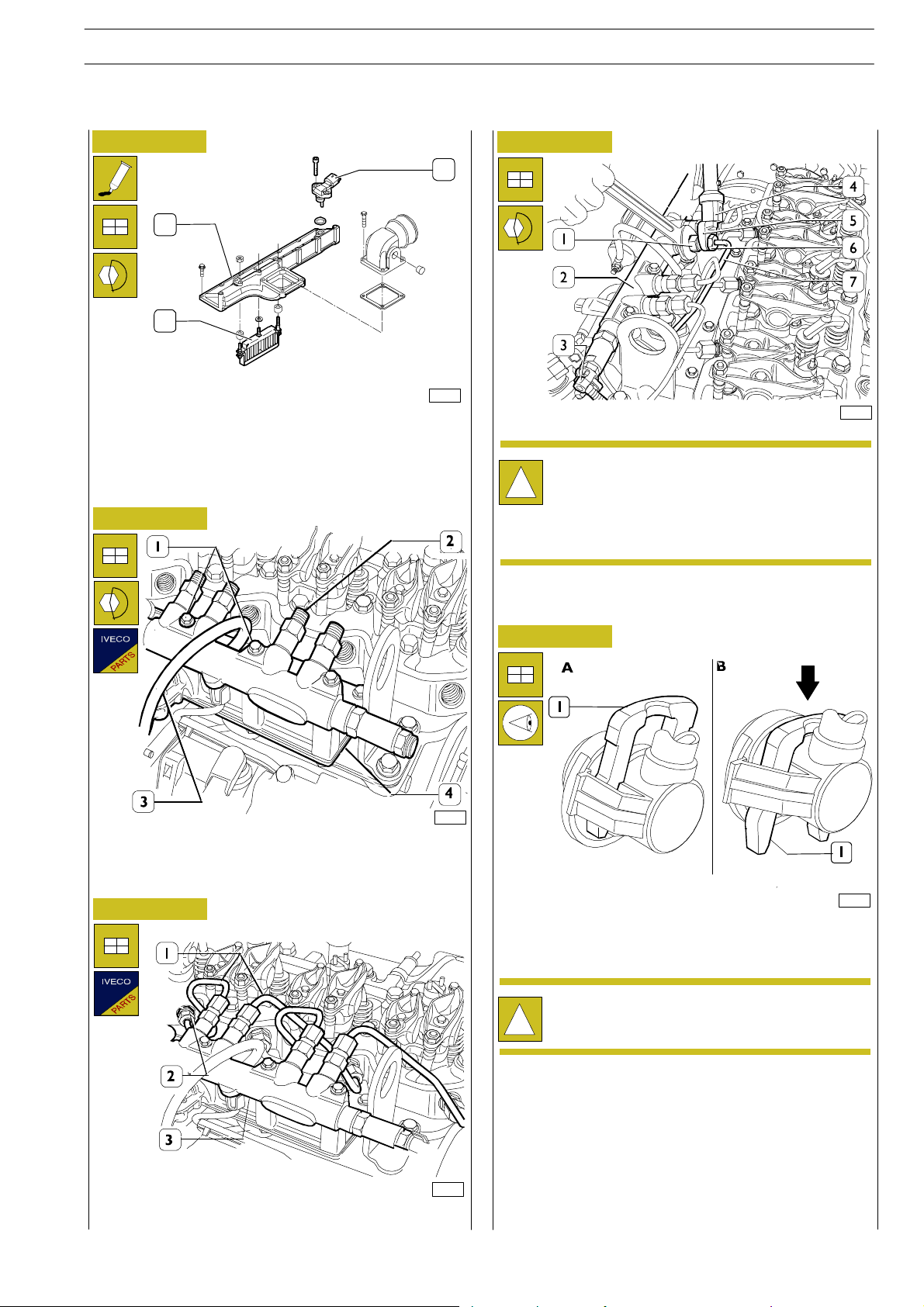
Apply to the coupling surface of the intake manifold (1)
equipped with heater (2) a sufficient coat of LOCTITE 5999
and provide tightening the screws to the prescribed matching
couple.
Figure 83
Figure 85
74181
Pipe (7) connections shall be tightened to 20 Nm
torque, using the proper wrench (5) and the torque
!
wrench 99389833 (4).
Connections (6) shall be tightened by holding the
flow limiting valve hexagon (1) wit h the proper
wrench.
Connect the fuel pipe (3) to the rail (2) following the
procedure shown in the following figure.
z
74179
Fit the rail (2) and tighten the screws (1) to the specified
torque, c onnect the ground cable (3) to the intake manifold
(4) and tighten the fastening nut to the specified torque.
Figure 84
Figure 86
70126
Press the clamp (1) in arrow direction (FigureB) and connect
the pipe to the rail, reset the clamp to th e initial locking
position “A”.
Check proper fuel pipe connection.
!
74180
Connect new fuel pipes (1) to rail (3) and injector manifolds
(2).
Page 66
28
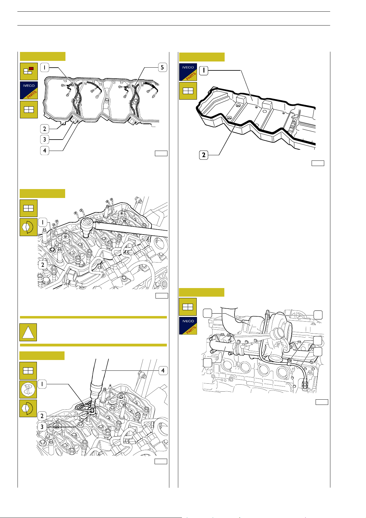
SECTION 3 - DUTY - INDUSTRIAL EQUIPMENT NEF ENGINES
ED. FEBRUARY 2003
Figure 87
70352
Check electrical cable (5) conditions, replace if damaged by
cutting the support (2) clamps and removing the screws (4)
that secure it to connections (3).
Fit a new gasket (1) on the support (2).
Figure 88
Figure 90
70355
Fit a new gasket (2) on the tappet cover (1).
Place the tappet cover on, install the bolts in the correct
position and tighten.
70353
Fit the w iring support (2) and tighten the screws (1) to the
specified torque.
Before any assembly operation always verify that the
hole and screw threads have no evidence of wear or
!
dirt.
Figure 89
70354
Connect the electrical cables (1) to the injectors (3) and use
the torque wrench 99389834 (4) to tighten the fastening
nuts (2) to the specified torque.
Figure 91
1
5
4
3
2
74172
Reconnect the exhaust manifold (2) with new gaskets.
Tighten the fastening screws (1) to the specified torque.
Sling the turbocharger (1) and place it over the manifold after
having first inserted a new gasket.
Connect the oil pipeline (3) to the support of the heat
exchanger /oil filter. Fix the pipe (3) to the pipe fitting on th e
turbocharger through the clamp (4) and the screw locking to
the block.
Page 67
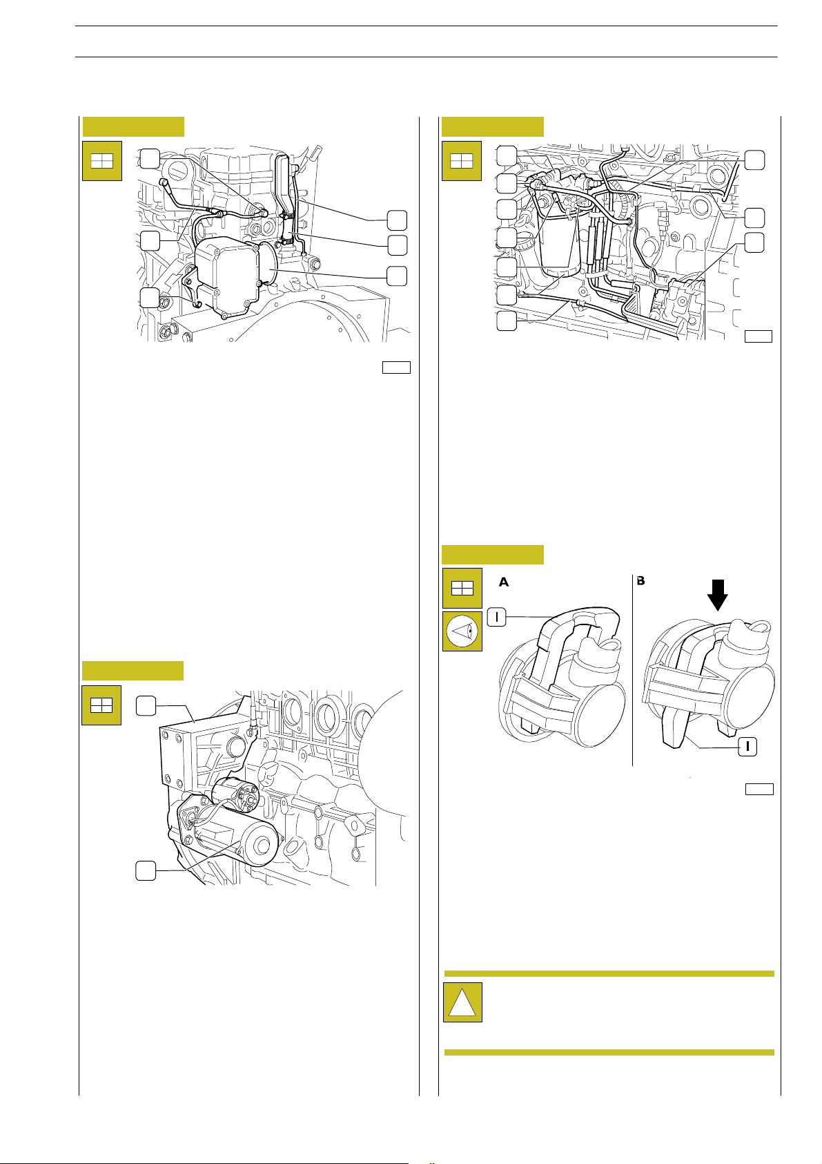
NEF ENGINES
ED. FEBRUARY 2003
SECTION 3 - DUTY - INDUSTRIAL EQUIPMENT
29
Figure 92
1
6
2
5
4
3
74170
Insert the blow-by filter (4) tightening the screws.
Connect th e pipeline (6) and fix the oil vapour recover pipe
through the clamp (5); lock up the nut fixing it to the upper
edge.
Connect the pipeline (2) to th e pressure- limiter (1).
Completion of the engine
Properly handle the engine holding it by a lifter, remove it
from the rotating shaft, remove the brackets 99341009 and
place it on proper suitable support to carry out the
completion.
Proceed assembling t h e oil filter.
Figure 94
1
10
2
3
4
9
8
5
6
7
74165
Assemble the bracket and the support (1) of the fuel filter (6).
Proceed connecting in sequence the pipelines (9,3,4 and 5)
of the support (1) to the high pressure pump (8).
Connect the pipeline (7) from the high pressure pump to the
engine control module heat exchanger.
Connect th e pipeline (10) from the high pressure pump to
the rail diffuser.
Figure 95
Figure 93
1
2
Assemble the starter (2) to the internal part of the flywh eel
cover.
Assemble the oil feeding pipe using a new O-ring. Fix with
three M12x25 screws.
70126
All the fuel pipelines are fixed using the clamps shown in the
picture.
For the connection of the pipes, press the clamp (I) following
the arrow’s direction (Figure B) and connect the pipe to the
clamp on the high pressure pump or on the support of the
fuel filter.
Reset the clamp in the initial locking ”A” position.
In case the pipes are re-employed, they must keep
the sealing tops at the edges.
!
Make sure that the fuel pipeline is correctly
connected.
Reconnect the engine harness to all the sensors, the engine
control module and the rail diffuser (see Figure 6)
Page 68
30
SECTION 3 - DUTY - INDUSTRIAL EQUIPMENT NEF ENGINES
ED. FEBRUARY 2003
Checks and inspections
The following checking inspections must be carried
out after the engine assembly on the vehicle .
!
Start the engine and leave it running just above the
idling speed, wait unt il the coolant reaches the
temperature necessary to open the thermostat and
then check:
- that there are no water leaks from the connecting
sleeves of engine cooling circuit pipes and cab internal
heating pipes, tighten the clamping collars if required;
- check carefully the connection between the low
pressure fuel pipes and the relevant connectors;
- that there are no oil leaks between the c over and the
cylinder head, between oil sump and engine block,
between heat exchanger oil filter and the relevant
housings and between the different pipes in the
lubricating circuit;
- that there are no fuel leaks from the fuel pipes;
- that there are no air leaks from pneumatic pipes (if
fitted);
- check also proper operation of the warning lights set on
the instrument panel and of the equipment
disconnected when engine was removed.
- Carefully check and bleed the engine cooling equipment
by repeated draining operations.
Page 69
NEF ENGINES
ScrewM6
for
fastening
injector
t
}
ED. FEBRUARY 2003
SECTION 3 - DUTY - INDUSTRIAL EQUIPMENT
TIGHTENING TORQUE
COMPONENT TORQUE
Nm kgm
Studs M6 for camshaft sensors 8 ± 2 0.8 ± 0.2
Studs M8 for feed pump 12 ± 2 1.2 ± 0.2
Screw M12 for fasten i ng rear gear case
Screw M10 for fasten i ng rear gear case
Screw M8 for fastening rear gear case
Nut M6 for fastening c amshaft sensor 10 ± 2 1 ± 0.2
st
stage
Screw M8 for fastening oil pump
1
nd
2
stage
Screw M8 for fastening front cover 24 ± 4 2.4 ± 0.4
Screw M8 for fastening c amshaft longitudinal retaining plate 24 ± 4 2.4 ± 0.4
Screw M8 for fastening camshaft gear 36 ± 4 3.6 ± 0.4
Screw M10 for fastening crankcase plate 43 ± 5 4.3 ± 0.4
Nut M18 for fastening high pressure pump gear 105 ± 5 10.5 ± 0.5
Nuts M8 for fastening fuel pump 24 ± 4 2,4 ± 0,4
½ inch plug on cylinder head
¼ inch plug on cylinder head
¾ inch plug on cylinder head
s
Nut fastening for injector feed connector 50 ± 5 5 ± 0.5
Nut M6 for flame start grille on intake manifold 8 ± 2 0.8 ± 0.2
Screw M8 for fastening intake manifold 24 ± 4 2.4 ± 0.4
Screw M12 for fasteni ng rear brackets for engine lift i ng 77 ± 12 7.7 ± 1.2
Screws M8 for fastening Common Rail 24 ± 4 2.4 ± 0.4
Connectors M14 for high pressure fuel pipes 20 ± 2 2 ± 0.2
Screw M12 (12 x 1.75 x 130) for fastening cylinder head
Screw M12 (12 x 1.75 x 150) for fastening cylinder head
s
1
stage
nd
2
stage
rd
stage 90º ± 5º
3
Screw for fastening rocker bracket
Valve clearance adjustin g nuts 24 ± 4 2.4 ± 0.4
Nuts M14 for fastening fuel pipes from high pressure pump to Common Rail 20 ± 2 2 ± 0.2
Screw M8 for fastening high pressure pipe connector 24 ± 4 2.4 ± 0.4
Screw M6 for fastening w irin g bulkhead 10 ± 2 1 ± 0.2
Screw M8 for fastening electric wiring support for injector feed 24 ± 4 2.4 ± 0.4
Nuts for fastening wiring on each injector 1,5 ± 0,25 0.15 ± 0.025
Screw M12 for fastening fuel filter bracket 77 ± 8 7.7 ± 0.8
Screw M8 for fastening fuel filter holder 24 ± 4 2.4 ± 0.4
Fuel filter contact + ¾ turn
Screw M22 for fast ening oil pressure relief valve on oil filter support 80 ± 8 8 ± 0.8
Screw M8 for radiator seal and oil filter support 24 ± 4 2.4 ± 0.4
Oil filter contact + ¾ turn
77 ± 12
47 ± 5
24 ± 4
8 ± 1
24 ± 4
24 ± 4
36 ± 5
12 ± 2
7.7 ± 1.2
4.7 ± 0.5
2.4 ± 0.4
0.8 ± 0.1
2.4 ± 0.4
2.4 ± 0.4
3.6 ± 0.5
1.2 ± 0.2
8,5 ± 0,35 0.35 ± 0.035
75º ± 5º
35 ± 5 3.5 ± 0.5
55 ± 55.5± 0.5
90º ± 5º
36 ± 5 3.6 ± 0.5
31
Page 70
32
ScrewM12forfasteningdamperadapter1stage
{
6-cyl
4.3±0.6
{
p
insM
8
7±1
ScrewM12forfasteningengineflywheel1stag
e
SECTION 3 - DUTY - INDUSTRIAL EQUIPMENT NEF ENGINES
COMPONENT TORQUE
11/8inchconnectiononfiltersupport for turbine lubrication 24 ± 4 2.4 ± 0.4
Nut M12 for fastening turbine lubrication pipe 10 ± 2 1 ± 0.2
Screw M10 for fastening engine coolant inlet connection 43 ± 6 4.3 ± 0.6
90° elbow fastening (if required) to engine coolant inlet connection 24 ± 4 2.4 ± 0.4
Pipe on cylinder head for compressor cooling 22 ± 2 2.2 ± 0.2
Screw M6 for fastening engine c oolant drain connector 10 ± 2 1 ± 0.2
Pin fastening on engine block for exhaust manifold 10 ± 2 1 ± 0.2
Screw M10 for fastening exhaust manifold on cylinder head 53 ± 5 5.3 ± 0.5
Screw M12 for fastening damper adapter 1ststage
and damper on output shaft 2ndstage
Screw M10 for fastening pulley on output shaft
Screw M8 for fastening water pump 24 ± 4 2.4 ± 0.4
Screw M10 for fastening auxiliary component control belt tensioners 43 ± 6 4.3 ± 0.6
Screw M10 for fastening fixed pulleys for au xiliary component control belt 43 ± 6 4.3 ± 0.6
Screw M10 for fastening flywheel housing
Screw M12 for fastening flywheel housing
Screw M6 for fastening heat exchanger for control unit
Screw M8 for fastening heat exchanger for control unit
Connection M12 for fuel inlet-outlet on heat exchanger 12 ± 2 1.2 ± 0.2
Nut M8 for fastening valve cover 24 ± 4 2.4 ± 0.4
Screw M6 for fastening camshaft sensor 8 ± 2 0.8 ± 0.2
Screw M6 for fastening output shaft sensor 8 ± 2 0.8 ± 0.2
Screw M14 for fastening coolant temperature sensor 20 ± 3 2 ± 0.3
Screw M5 for fast ening oil pressure/temperature sensor 6 ± 1 0.6 ± 0.1
Screw for fastening fuel pressure sensor 35 ± 5 3.5 ± 0.5
Screw M14 for fastening fuel temperature sensor 20 ± 3 2 ± 0.3
Screw for fastening air temperature/pressure sensor on intake manifold 6 ± 1 0.6 ± 0.1
Screw M12 for fastening engine oil level sensor 12 ± 2 1.2 ± 0.2
6-cyl.
.
Turbine fixing to exhaust manifold
4-cyl.
Adapter M 12 on turbine for lubricant oil pipes (inlet)
Pipe fixing on adapter M10 for turbine lubrication 35 ± 5 3.5 ± 0.5
Oil pipe fixing on adapter M10 for tu rbine lubrication to block 43 ± 6 4.3 ± 0.6
Oil drain pipe fixing M8 on turbine 24 ± 4 2.4 ± 0.4
Connector fixing M6 for oil return from cylinder head to flywheel housing 10 ± 2 1 ± 0.2
Screw M12 for fastening engine flywheel 1ststage
Screw M8 for fastening front bracket for engine lifting 24 ± 4 2.4 ± 0.4
Screw for fastening engine oil sump 24 ± 4 2.4 ± 0.4
Alternator 2.4 ± 0.4
M10 Screw, Bracket fixing on water feed pipefitting 43 ± 6 2.4 ± 0.4
M10 Screw, alternator locking 43 ± 6 2.4 ± 0.4
Starter 2.4 ± 0.4
Starter fixing screw 43 ± 6 2.4 ± 0.4
ED. FEBRUARY 2003
pins M8
nutsM8
nuts M8
2ndstage
Nm kgm
50 ± 5 5 ± 0.5
90º
68 ± 7 6.8 ± 0.7
85 ± 10
49 ± 5
10 ± 2
24 ± 4
7 ± 1
43 ± 6
24 ± 4
35 ± 5 3.5 ± 0.5
30 ± 4 3 ± 0.4
60º ± 5º
8.5 ± 1
4.9 ± 0.5
1 ± 0.2
2.4 ± 0.4
0.7 ± 0.1
0.7 ± 0.1
2.4 ± 0.4
Page 71

NEF ENGINES
DIAGNOSI
ED. FEBRUARY 2003
SECTION 3 - DUTY - INDUSTRIAL EQUIPMENT
33
PART TWO - ELECTRICAL EQUIPMENT
Page 72

34
SECTION 3 - DUTY - INDUSTRIAL EQUIPMENT NEF ENGINES
DIAGNOSI
ED. FEBRUARY 2003
Page 73
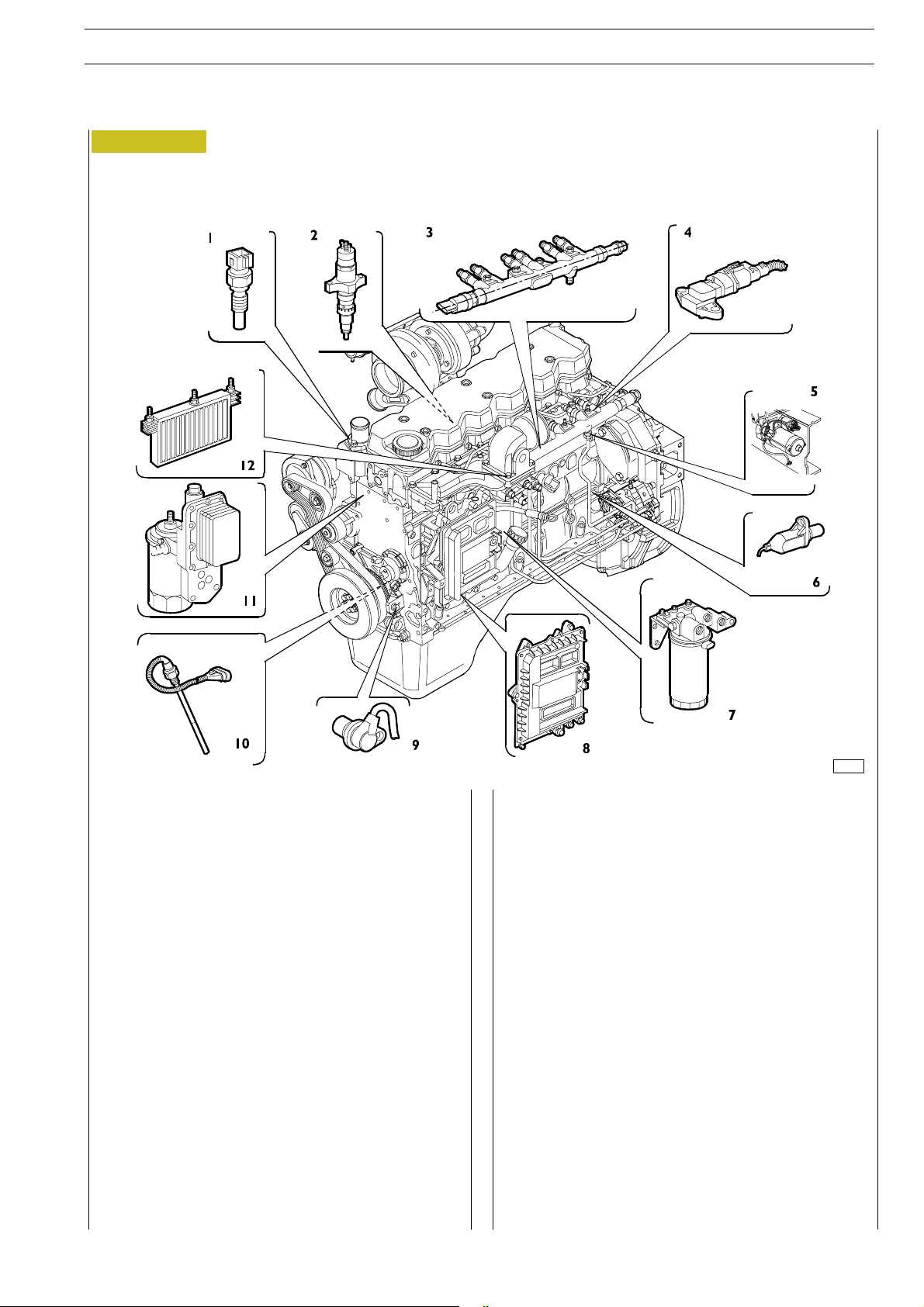
NEF ENGINES
PLACEMENT OF SENSORS
Figure 96
ED. FEBRUARY 2003
SECTION 3 - DUTY - INDUSTRIAL EQUIPMENT
35
The NEFF4A0684 and F4AE0484 engines are fully driven by
the electronic engine control module, which is assembled directly to the engine by means of a heat exchanger enabling its
cooling, utilising rubber buffers to reduce vibration originated
by the engine.
Through the engine control module it is possible to verify the
correct working of the engine. (See part three of the hereby
user’s guide specifically dedicated to diagnostic).
74190
The electrical and electronic components of the engine are
listed here following:
1. Temperature sensor of cooling liquid;
2. Electro-injector (from 4 to 6, according to whether the
engine has 4 of 6 cylinders configuration);
3. Pressure sensor assembled to rail diffuser;
4. Temperature and air pressure sensor;
5. Starter;
6. Timing system sensor;
7. Fuel temperature sensor;
8. EDC7 electronic module;
9. Driving shaft sensor;
10. Engine oil level transmitter;
11. Sensor of engine’s oil temperature and pressure;
12. Pre-post heating resistor.
Page 74
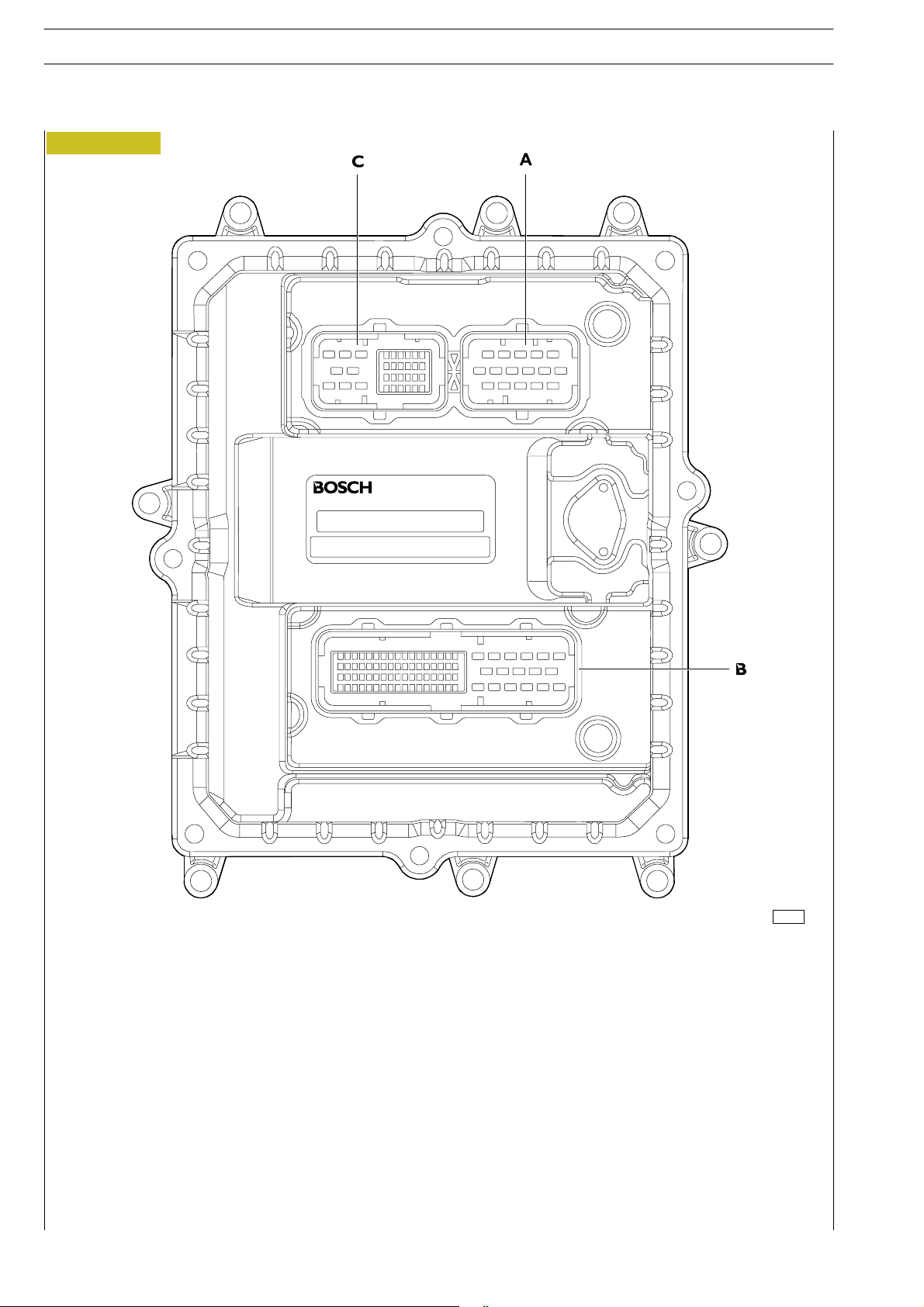
36
SECTION 3 - DUTY - INDUSTRIAL EQUIPMENT NEF ENGINES
ED. FEBRUARY 2003
EDC7 ECU
Figure 97
01525t
A - Connector to injectors; B - Connector to chassis (Provide reference of the vehicle to which the engine is assembled);
C - Connector to sensors.
Page 75
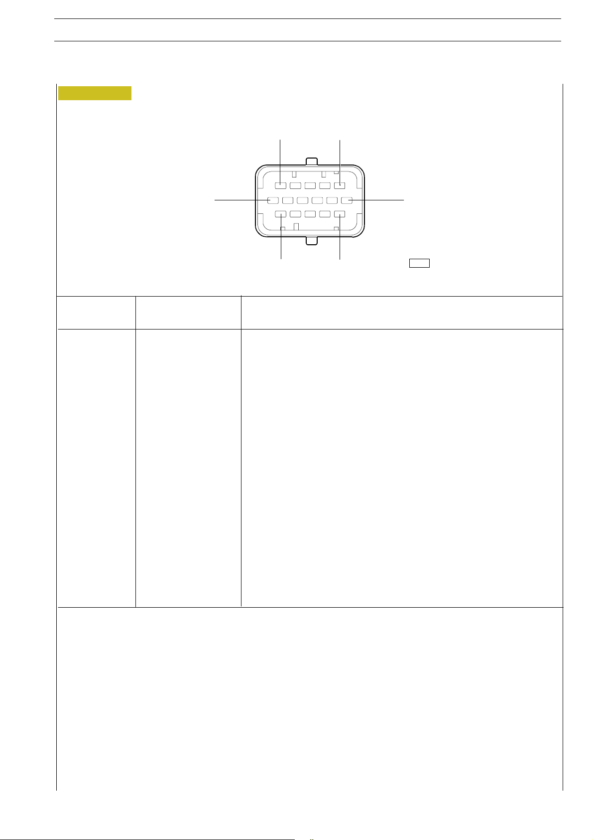
NEF ENGINES
Connector to injectors (A)
Figure 98
ED. FEBRUARY 2003
SECTION 3 - DUTY - INDUSTRIAL EQUIPMENT
37
12
1
16
5
PIN ECU CABLE COLOUR FUNCTION
1
2
3
4
5
6
7
8
9
10
11
12
13
14
15
16
-
-
RU
WP
WV
RW
-
-
RG
UN
UG
WR
RY
W
UO
UY
-
-
Injector cylinder 2
Injector cylinder 3
Injector cylinder 4
Injector cylinder 2
Earth
Injector cylinder
Injector cylinder 1
Injector cylinder 6 (*)
Injector cylinder 5 (*)
Injector cylinder 3
Injector cylinder 1
Injector cylinder 4
Injector cylinder 6 (*)
Injector cylinder 5 (*)
116
50350
Colour legend
BBlack
RRed
UBlue
WWhite
PPurple
G Green
NBrown
Y Yellow
OOrange
(*) Only for 6 cyl. versions.
Page 76
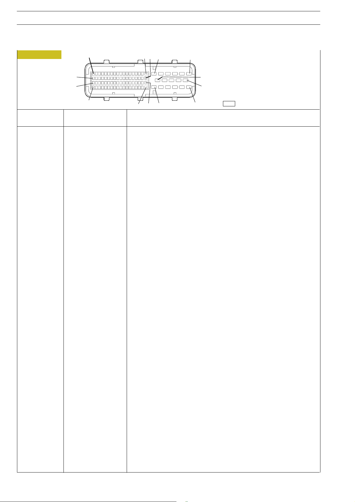
38
SECTION 3 - DUTY - INDUSTRIAL EQUIPMENT NEF ENGINES
ED. FEBRUARY 2003
Feed connector (B) to components and to functions of the specific equipment
Figure 99
71
53
35
89
18
6
5472
36 17
1
11
7
12
PIN ECU CABLE COLOUR FUNCTION
1
2
3
4
7
8
9
12/13
14/15
16
19
20
27
28
31
32
36
37
39
44
45
46
49
50
52
53
55
62
63
64
72
73
78
81
83
87
88/89
8150
0087
0000
8885/0159
8150
7777
0000
8150
0000
0094
0150
8153
0156
5535
2298
-
8837
8888
8051
9905
9906
5553
5584
0158
6109
6108
5158
0160
5503
0535
0159
0159
8162
0157
5157
-
-
Positive driven by battery
Negative for switch of fuel filter heater/starter
Earth
Positive for pre-post heating resistor
Positive driven by battery
Positive for blink-code button/ oil low pressure led/ pre-heating led/
Air conditioner switch (if available) (*)/EDC
Earth
Positive driven by battery
Earth
Negative for post-heating resistor
Negative start-stop push buttons from eng./accelerator pressed (**)
Positive from change over switch to key in starting phase (+50)
Positive from blink-code button
Positive for EDC diagnostic led
K Line for diagnosis connector, 30 poles (2 pin)
Negative for multi-switch couple-limiter (*)
Positive for fuel filter heating switch
Positive for starter
Positive from key switch/ L line for diagnosis connector 30 poles (pin 11)
Negative from starter push button from engine (**)
Negative from engine stop push button from engine
Negative for pre-heating led in on position
Diagnosis connector (pin 28)
Negative from accelerator push button pressed (*)
CAN Line (whether equipped), diagnosis connector (pin 22)
CAN Line (whether equipped), diagnosis connector (pin 22
Positive for sensor of foot accelerator pedal pos.(**)/Earth multi-switch (*)
Negative for clutch sensor
Negative for engine oil low pressure led
Negative for EDC diagnosis led
Positive from pressed accelerator push button (**)/multi-switch signal (*)
Positive redundant from pressed accelerator push button (**)
Positive air conditioner device (whether equipped) (*)
Negative sensor of foot accelerator pedal pos.(**)/ Earth multi-switch (*)
Signal from sensor of foot accelerator pedal pos.(**)/ Signal multi-switch (*)
Positive for couple multi-switch limiter (*)
-
03210t
(*) F4AE0684H - E
(**)F4AE0684F
Page 77
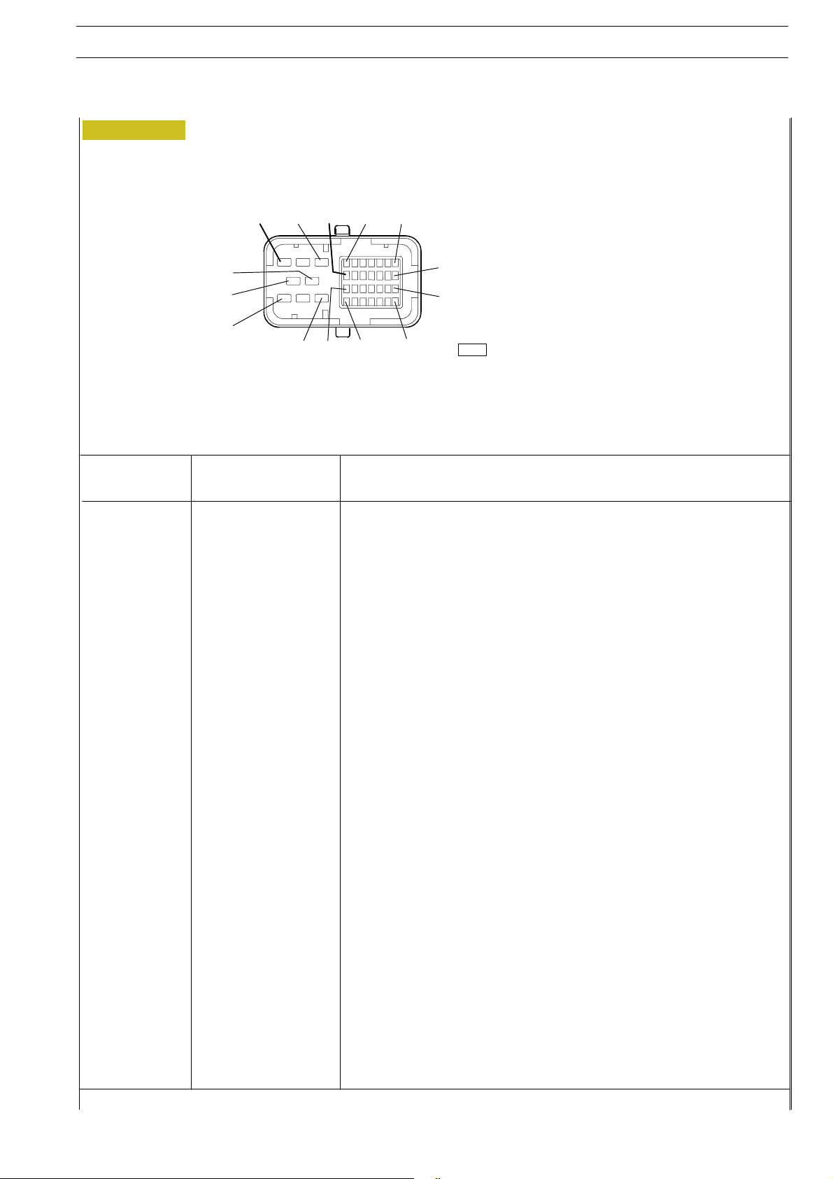
NEF ENGINES
Connector to sensors (C)
Figure 100
ED. FEBRUARY 2003
SECTION 3 - DUTY - INDUSTRIAL EQUIPMENT
Colour legend
39
PIN ECU
5
7
9
10
12
17
18
19
20
21
23
24
25
27
28
29
30
33
34
35
36
8
6
5
4
1
323
CABLE COLOUR
NW
NP
PY
NY
GY
YR
YN
PN
GN
N
U
U
R
GO
NG
UO
R
PO
YU
PG
YO
16
15
9
BBlack
RRed
UBlue
22
WWhite
PPurple
29
G Green
NBrown
Y Yellow
30
36
03211t
OOrange
FUNCTION
Earth for pressure regulator
Pressure regulating drive
Feed for engine oil temperature/pressure sensor
Feed for air pressure and temperature sensor
Feed for rail pressure sensor
Earth for fuel temperature sensor
Earth for cooling liquid temperature sensor
Earth for engine oil temperature - pressure
Feed for rail pressure sensor
Feed for air pressure - temperature sensor
Timing system sensor
Driving shaft sensor
Driving shaft sensor
Signal from rail pressure sensor
Signal from air pressure sensor
Signal from air temperature sensor
Earth for timing system sensor
Signal from engine oil temperature sensor
Signal from fuel temperature sensor
Signal from engine oil pressure
Signal from cooling oil temperature
Page 78
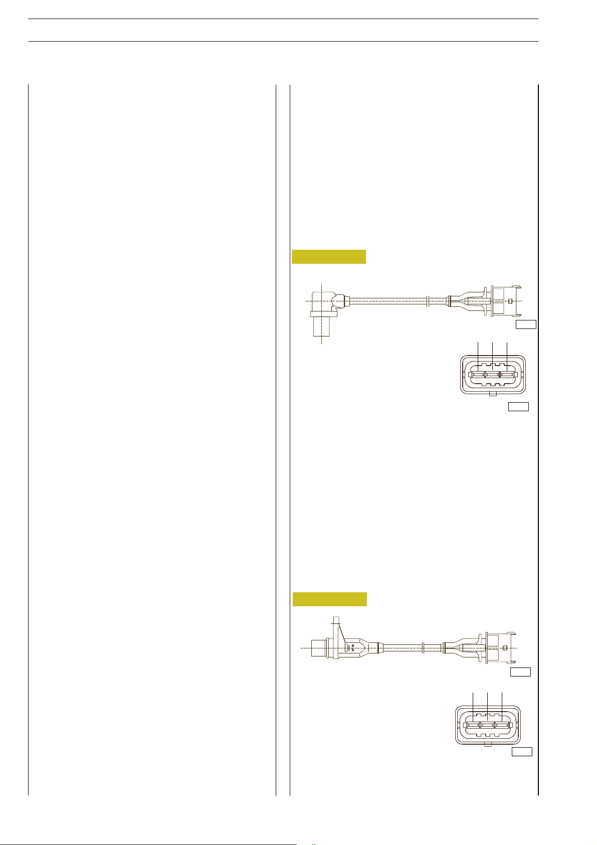
40
SECTION 3 - DUTY - INDUSTRIAL EQUIPMENT NEF ENGINES
ED. FEBRUARY 2003
Temperature and air-pressure sensor
It is a component integrating one temperature sensor and a
pressure one.
It is assembled to the suction inlet manifold and measures the
maximum capacity of air introduced, in order to provide to the
engine control module the necessary data to calculate the
quantity of fuel to be injected per each cycle.
It is connected to the engine control module by 21C and 29C
pin (temperature), 10C and 28C (pressure) and has a 5 volt
feeding.
21C Earth
29C NTC signal (temperature)
10C +5V feed
28C Signal (pressure)
Sensor of engine’s oil temperature and
pressure
It is a component integrating one temperature sensor and a
pressure one.
It is assembled to the engine oil filter in horizontal position.
It measures the temperature and the pressure of the engine’s
oil.
It is connected to the engine control module by 19C and 33C,
9C and 35C.
19C Earth
33C NTC signal (temperature)
9C +5V feed
35C Signal (pressure)
Drivingshaftsensor
It is an inductive type sensor and it is placed on the front left
part of the engine.
It generates some signals originated by the magnetic flow lines
that close up through the openings of a phonic wheel splined
to the driving shaft. The same signal is utilised to control the
eventual electronic engine speed indicator placed on the vehicle instrument board.
It is connected to the engine control module by pin 25C (signal) and 24C (signal). The third pin is for screening.
The resistance value of the sensor is of about 900 Ω.
Figure 101
50319
2
1
3
50342
Timing system sensor
It is an inductive type sensor and it is placed on the back left
part of the engine.
It generates some signals originated by the magnetic flow lines
that close up through the ports drilled on the gear splined to
the camshaft. The signal generated by this sensor is utilised by
the electronic engine control module as signal of injection
phase.
Even being equal to the flywheel sensor it is not interchangeable since the external shape is different.
It is connected to the engine control module by pin 23C (signal) and 30C (signal). The third pin is for screening.
The resistance value of the sensor is of about 900 Ω.
Figure 102
50320
2
1
3
50342
Page 79
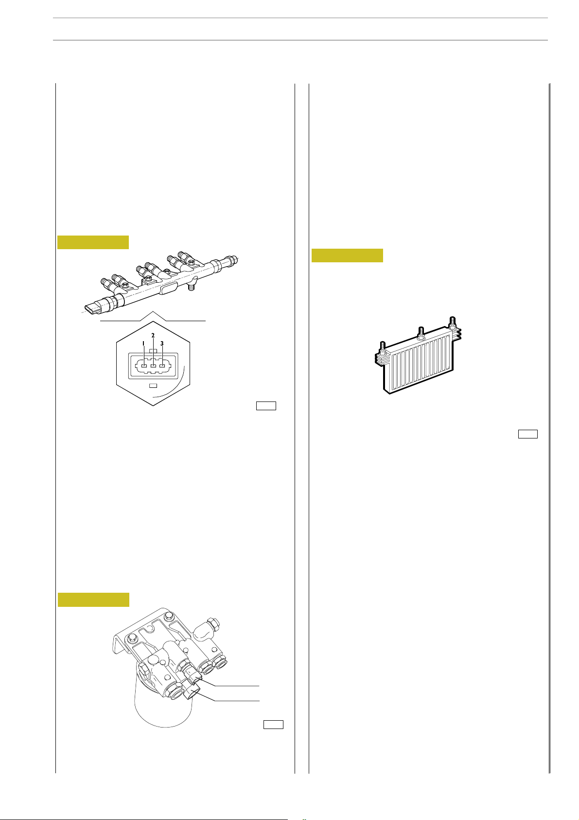
NEF ENGINES
ED. FEBRUARY 2003
SECTION 3 - DUTY - INDUSTRIAL EQUIPMENT
41
Fuel pressure sensor
It is a sensor assembled to one end of the rail and measures
the pressure of the fuel available in order to determine the injection pressure.
The value of the injection pressure is utilised to control the
pressure itself and to determine the duration of the electronic
injection device.
It is connected to the engine control module by pin 20C
(Earth), 27C (signal) and 12C (feed).
It has 5 volt feeding.
Figure 103
Resistor pre-post heating
It is a resistor placed on the suction inlet manifold and is utilised
to heat the air during the heating pre-post operations.
It is fed by a tele -switch usually placed very close to the engine.
The resistor is for aprx. 0,5 kΩ.
The relay drive i s connected to the gearbox by pin 4 and 16
of the chassis connector.
The drive is acti vated with water and/or fuel temperature <
5ºC.
Figu re 105
02112t
1 - Earth; 2- Signal; 3- Feed.
Fuel temperature sensor
It is a sensor with variable resistor, able to detect the fuel temperature to provide to the engine control module an index of
the fuel thermal status.
It is connected to the engine control module by pin 17C
(Earth) and 34C (temperature signal).
Theresistorto20ºC=2,5kΩ.
Figu re 104
1
2
02158t
Cooling liquid temperature sensor
It is a sensor with variable resistor, able to detect the cooling
liquid temperature to provide to the engine control module
an index of the engine thermal status.
Usually, the same signal is driven by the engine control module
to the temperature device placed within the vehicle’s dashboard.
It is connected to the engine control module by pin 18C
(Earth) and 36C (temperature signal).
Theresistorto20ºC=2,5kΩ.
1 - Fuel temperature sensor; 2 - Resistor
50348
Page 80
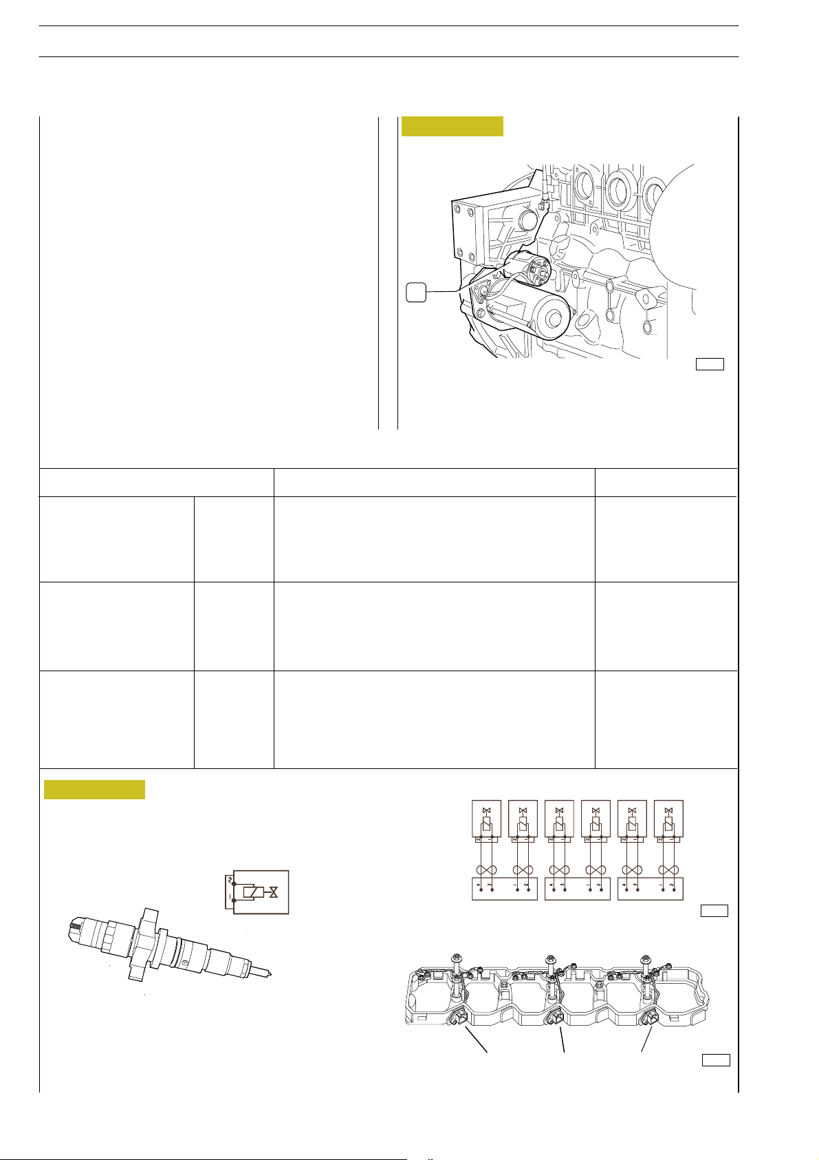
42
SECTION 3 - DUTY - INDUSTRIAL EQUIPMENT NEF ENGINES
ED. FEBRUARY 2003
Starter
The starter is usually driven by the starting block assembled to
the vehicle’s dashboard and provides positive voltage to pin
B20 of the EDC.
Electro-injectors
CONNECTOR 1
CONNECTOR 2
1
2
3
4
1
2
3
4
Injector cylinder 2
Injector cylinder 2
Injector cylinder 1
Injector cylinder 1
Injector cylinder 4
Injector cylinder 4
Injector cylinder 3
Injector cylinder 3
DESCRIPIONREFERENCE
Figure 106
A
74166
A- Feeding relay of the starter
PIN EDC
3A
6A
13 A
9A
5A
14 A
12 A
4A
CONNECTOR 3
(only for 6 cyl. versions)
Figure 107
1
2
3
4
Injector cylinder 6
Injector cylinder 6
Injector cylinder 5
Injector cylinder 5
Fan side
10 A
15 A
16 A
11 A
13
13
2
2
50343
50349
Page 81

NEF ENGINES
DIAGNOSI
ED. FEBRUARY 2003
SECTION 3 - DUTY - INDUSTRIAL EQUIPMENT
43
PART THREE - TROUBLESHOOTING
Page 82

44
SECTION 3 - DUTY - INDUSTRIAL EQUIPMENT NEF ENGINES
DIAGNOSI
ED. FEBRUARY 2003
Page 83
NEF ENGINES
GENERALDIAGNOSI
PREFACE
ED. FEBRUARY 2003
SECTION 3 - DUTY - INDUSTRIAL EQUIPMENT
45
A successful troubleshooting is carried out with the competence acquired by years of experience and attending training
courses.
When the user complains for bad efficiency or working
anomaly, his indications must be kept into proper consideration using them to acquire any useful information to focus the
intervention.
After the detection of the existing anomaly, it is recommended
to proceed with the operations of troubleshooting by decoding the auto-troubleshooting data provided by the EDC system electronic central unit.
The continuous efficiency tests of the components connected
to, and the check of working conditions of the entire system
carried out during working, c an offer an important diagnosis
indication, available through the decoding of the ”failure/
anomaly” codes issued by blinking of the failure led: the ”blinkcode” (whether programmed).
Please consider that the interpretation of the indications provided by the blink-code is not sufficient to guarantee the solution to the existing anomalies.
Using IVECO processing instruments, it is also possible to establish a bi-directional connection with the central unit, by
which not only to decoding the failure codes but also input an
enquiry relying on memory files, in order to achieve any further
necessary information to identify the origin of the anomaly.
Every time there is a breakdown claim and this breakdown is
actually detected, it is necessary to proceed inquiring the electronic unit in one of the ways indicated and then proceed with
the diagnostic research making trials and tests in order to have
a picture of the working conditions and identify the root
causes of the anomaly.
In case the electronic device is not providing any indication, it
will be necessary to proceed relying on the experience, adopting traditional diagnosis procedures.
In order to compensate the operators’ lack of experience in
this new system, we are hereby providing the USER’s GUIDELINE FOR TROUBLESHOOTING in the following pages.
The GUIDELINE is composed of three different parts:
- Blink Code, relating to the anomalies identified by the
gearbox, mainly of electric and electrical nature;
- Troubleshooting guide using PT-01 portable tester.
Tool identified as IVECO p/n 8093731.
- Guideline for troubleshooting without blink code, divided
per symptoms, describing all possible anomalies not detected by the electronic gearbox, often of mechanical and
hydraulic nature.
Any kind of operation on the electronic center unit
must be executed by qualified personnel, duly
!
authorized by IVECO.
Any unauthorized tamper will involve decay of
after-sales service in warranty.
Page 84

46
SECTION 3 - DUTY - INDUSTRIAL EQUIPMENT NEF ENGINES
ED. FEBRUARY 2003
BLINK-CODE - GENERAL INFORMATION
Anomaly warning led
The ECU is continuously screening, by complex auto-diagnosis
routine procedures, its own working conditions as well as the
conditions of the components connected to, and of the engine.
The detection of the anomaly provokes the lightening up of
the warning led on the monitor and drive board, with id.
modes allowing a first selection of the problem according to
the level of importance. (Review the User’s Manual of the vehicle equipped with NEF engine to know the precise position
of the pushbutton and of the led).
Led in off position (no light): no anomalies detected or
small entity anomaly with no prejudice safe working conditions.
Lighted Led: significant anomaly. In this condition it is rec
ommended to go to a diagnosis centre.
Blinking led: serious anomaly requiring immediate repair
intervention.
The emission of the codes of anomaly detected by autotroubleshooting and saved in ECU memory starts after having
pushed and r eleased the pushbutton. (Review the User’s Manual of the vehicle equipped with NEF engine to know the precise position of the pushbutton and of the led).
The led, usually aside the pushbutton, will signal the light blink
codes by to series of emissions with different frequency, highlighting the decimal numeration digits indicating the anomaly.
The slow blinking identify the unit where the anomaly occurs
(engine, injectors...) the fast blinking identify the specific failure.
A each push and release of the pushbutton, one only memory
code will be sorted. Therefore it is necessary to repeat the procedure until when an identical failure data to the first one received will be released as indication that all the failure file memory has been analysed.
In case of no filed anomalies in memory, the led will light up
when the pushbutton is pressed and will then turn off aprx. 1
second after release of the pushbutton without originating
blinking.
Note: applying to the blink code troubleshooting procedure,
it is possible to obtain information relating to currently occurringfailuresaswellastootheranomaliesoccurredinthepast
and not existing any more at present status.
Therefore it is absolutely necessary, at the end of every repair
intervention, to clear the failure file memory in order to avoid
that any future troubleshooting operation will detect any
solved anomaly whose root cause has already been corrected.
In the current equipment, clear operation is set pressing the
blink code pushbutton while the key change over switch is in
OFF position and keeping it pressed for 4 to 8 seconds after
turning the key change over switch in ON position.
Wait at least for 10 seconds before switching off the key
change over switch.
The evidence that the clearing operation has been correctly
made shall be obtained proceeding to switch OFF and ON
again the key change over switch and further require blink
code troubleshooting, that shall terminate with no display of
blink code.
Detectable failures:
Sensors:
- Air temperature boosting
- Fuel temperature
- Pressure boosting
- Unit pressure
- Flywheel
- Camshaft
- Fuel pressure
- Quantity of air flow sucked
Engine working:
- Engine runaway speed rate
- Injectors
- Fuel pressure driving system
- Pre-post heating driving system
Electro-valves:
- Fuel pressure gauge
Relé:
- Main relé
- Fuel electro-pump
- Heated fuel filter
Feed tension
Leds:
- Pre-post heating
Gearbox:
- Non-valid data set
- Incorrect saving of files in memory
- Power control bench 1
- Power control bench 2
- Internal failure (Gate Array)
- Sensor feed
- Internal failure (re-start)
- Incorrect engine disconnection
- Defective EEPROM
Data, features and performances are valid only if the
setter fully complies with all the installation
!
prescriptions provided by IVECO.
Furthermore, the users assembled by the setter shall
always be in conformance to couple, power and
number of turns based on which the engine has been
designed.
Page 85
NEF ENGINES
ED. FEBRUARY 2003
BLINK-CODE (SOFTWARE 3.3_1 VERSION)
SECTION 3 - DUTY - INDUSTRIAL EQUIPMENT
47
Recovery
Following from the detection of significant or serious anomaly,
the ECU also drives the set up of specific strategies to allow
safe utilisation of the engine and to limit some injection parameters within prescribed levels, based on the importance of
the problem.
The software applications currently in use, provide for four
In case of anomaly identified by intermitted blinking, that
means detected by the ECU and not existing any more, the
reduction of duty performances shall be active until disconnection of the engine.
The normal working conditions shall be recovered only at the
following start-up, while the anomaly data will be ”saved” in
the failure file memory.
safety levels characterised by the reduction of the vehicle’s
duty performances.
The table relating to the blink-codes reports some values of
power reduction, that actually indicate the limitation of duty
performances, automatically set by the gearbox based on the
anomaly occurring.
Blink-Code EDC Led Description of anomaly Power reduction
ENGINE
2.1 On Signal from cooling liquid temperature sensor 0
2.2 Off Signal from air temperature sensor, boosting 0
2.3 Off Signal from fuel temperature sensor 0
2.4 On Signal form sensor of pressure boosting 0
2.5 Off Signal from atmospheric pressure sensor 0
2.6 On Signal from oil pressure sensor 0
2.7 Off Signal from oil temperature sensor 0
2.8 Off Signal from heated filter driving relé 0
2.9 Off Signal from pre-post heating resistor driving relé 0
3.7 On Battery tension 0
3.8 Off Alert led pre-post heating 0
3.9 Off Pre-post heating resistor 0
INJECTORS
5.1 On Electro-valve injector of cylinder 1 0
5.2 On Electro-valve injector of cylinder 2 0
5.3 On Electro-valve injector of cylinder 3 0
5.4 On Electro-valve injector of cylinder 4 0
5.5 On Electro-valve injector of cylinder 5 (*) 0
5.6 On Electro-valve injector of cylinder 6 (**) 0
5.7 On Power stage 1 (cylinders 1-4) 0
5.8 On Power stage 2 (cylinders 2-3) 0
Power reduction:
0 = no power reduction
1 = performance comparable to equivalent engine but in suction stroke
2 = 50% of couple
3 = Limited engine speed
4 = Engine disconnection
(*): not applicable for the 4 cylinders
Page 86
48
SECTION 3 - DUTY - INDUSTRIAL EQUIPMENT NEF ENGINES
ED. FEBRUARY 2003
Blink-Code EDC Led Description of anomaly Power reduction
ENGINE RUNNING
6.1 On Signal from engine driving shaft sensor 2
6.2 On Signal from camshaft sensor 2
6.3 On Reliability of engine speed signal 0
6.4 Blinking Engine runaway speed rate 0
6.5 Off Relé of the starter 0
DASHBOARD INTERFACE
7.2 Off CAN Line (For vehicles equipped with electrical system
provided with CAN Line)
7.6 Off Oil pressure alert led 0
FUEL PRESSURE
8.1 Blinking Control fuel pressure 3
8.2 Blinking Fuel pressure signal 3
8.3 Blinking Pressure regulating electro-valve 3
8.4 Blinking Intervention to double stage boosting valve 3
8.5 Blinking Rail Min/Max pressure failure 4
EDC
9.4 On Main relè 0
9.6 On Gearbox disconnection procedure 3
9.7 On Sensor feed 0
0
Power reduction:
0 = no power reduction
1 = performance comparable to equivalent engine but in suction
stroke
2 = 50% of couple
3 = Limited engine speed
4 = Engine disconnection
Page 87

NEF ENGINES
REMARKS
ED. FEBRUARY 2003
SECTION 3 - DUTY - INDUSTRIAL EQUIPMENT
49
INTERVENTION
RECOMMENDED TESTS OR
Verify component correct working
and its resistor (2,5 kOhm at 20 ºC).
In case the component works, pro-
ceed checking the connection bet-
ween the sensor and the gearbox
connector to pin C18 - C36.
Readout of parameters using multi-
meter. Verify correct working of the
component and of its resistor bet-
ween pin 1 and 2 (R = 2,5 kOhm
at 20 ºC). If the sensor is working,
proceed checking the connection
between the sensor and the EDC
connector to pin C21 - C29.
Readout of parameters directly on
the sensor using multimetre . (R =
2,5 kOhm at 20 ºC). If the sensor
is working, proceed checking the
connection between the sensorand
the EDC connector to pin C17 -
C34.
Readout of parameters using mult i-
metre verifying feeding tension to
the sensor. (aprx. 5V).
In case of tension within specifica-
tion, check the wiring harness and
the connection between the sensor
and the EDC (Pin C10-C28).
ANOMALIES
POSSIBLE DERIVING
(*) = if available in the equipment
POSSIBLE CAUSE
(*) = if available in the equipment
EDC LED
BLINK
CODE
cooling liquid temperature, in positi-
veorearthorinopencircuit.
2.1 On Short circu it of the sensor of engine
combustion temperature, in positi-
veorearthorinopencircuit.(The
sensor is integrated with the air
pressure sensor).
2.2 Off Short circuit of the sensor of air
temperature, in positive or earth or
in open circuit.
2.3 Off Short circuit of the sensor of fuel
combustion pressure on suction
collector, in positive or earth or in
open circuit; or fed by tension out
of specification.
2.4 On Short circuit of the sensor of air
DIAGNOSI
Page 88

50
SECTION 3 - DUTY - INDUSTRIAL EQUIPMENT NEF ENGINES
ED. FEBRUARY 2003
REMARKS
The painting of the engine /EDC
may in fic iate on the correc t working
of the sensor.
INTERVENTION
RECOMMENDED TESTS OR
Apply for customer assistance for
the intervention on the EDC. The
sensor is integrated in the EDC and
is not replaceable singularly.
Readout of parameters using multi-
metre verifying feeding tension to
the sensor. (aprx. 5V).
In case of tension within specifica-
tion replace the sensor. In case of
tension out of specification, check
the wiring harness and the connec-
tion between the sensor and the
EDC (Pin C9-C35).
Sensor Readout u sing multimetre,
between pin 1 and 2. (R = 2,5
kOhm at 20 ºC).
If the sensor is working, proceed
checking the connection between
the sensor and the EDC (pin C19 -
C33).
Verify relé working status using the
troubleshooting device. If the result
is negative, replace the relé and test
again.
If th e anomaly still persists, check
the wiring harness and the connec-
tions between relé and EDC con-
nector (pin B2 - B36)
ANOMALIES
POSSIBLE DERIVING
(*) = if available in the equipment
POSSIBLE CAUSE
(*) = if available in the equipment
EDC LED
BLINK
CODE
pressure (integrated in EDC) in po-
sitiveorearthorinopencircuit
2.5 Off Short circuit of the sensor of air
oil pressure, in positive or earth or
in open circuit. (The sensor is inte-
grated with the oil temperature sen-
sor).
2.6 On Short circu it of the sensor of engine
oil temperature. (integrated with
the oil pressure sensor) , in positive
orearthorinopencircuit.
2.7 Off Short circu it of the sensor of engine
heating relé.
2.8 Off Incorrect working of the fuel filter
Page 89

NEF ENGINES
REMARKS
Eventually, the problem might not
depend on the too high or too low
ED. FEBRUARY 2003
tension but due to the incorrect de-
tection of tension by the EDC.
SECTION 3 - DUTY - INDUSTRIAL EQUIPMENT
Pre-heating is not working.
51
INTERVENTION
RECOMMENDED TESTS OR
Verify relé working s tatus using the
troubleshooting device. Check the
correct working of the relé (R=
aprx. 15 Ohm).
Incasethereléworks,checkthewi-
ring harness and the connections
between relé and EDC connector
(pin B4 - B16)
battery and on the recharge system.
If no anomaly is detected check the
efficiency of the Earth points and
the absence of fouling or oxidation
on the feed wiring connectors of
the EDC.
Verify working status using trouble-
shooting device.
If the result is negative replace the
led and drive t rou bleshooting ope-
ration again. If the failure persists
check connections and wiring har-
ness between led and EDC (pin
B46)
Using the multimetre, verify conti-
nuity of pre-heating resistor in the
suction collector (R = aprx. 0,5
Ohm).
If the component is working, check
the wiring harness and the connec-
tion between the resistor and the
relevant driving relé.
ANOMALIES
POSSIBLE DERIVING
(*) = if available in the equipment
Difficult starti ng with low external
temperature, exhaust fumes imme-
diately after starting.
Idling accelerated. Carry out the due controls on the
Led always on light even with star-
ting key in off position or always off.
Possible difficult starting (with low
external temperature) and exhaust
fumes at starting.
Possible difficult starting (with low
external temperature) and exhaust
fumes at starting.
POSSIBLE CAUSE
(*) = if available in the equipment
EDC LED
BLINK
CODE
heating drive relé.
2.9 Off Incorrect working of t he pre-post
3.7 On Signal for battery tension t oo high
or too low.
harness short circuit in positive or
earthorinopencircuit.
3.8 Spenta Defective pre-heating led o r wiring
correctly.
3.9 Spenta Pre-heating has not been working
Page 90

52
SECTION 3 - DUTY - INDUSTRIAL EQUIPMENT NEF ENGINES
ED. FEBRUARY 2003
REMARKS
Such failure may generate power
stage insuffic ien cy (in the EDC )
feeding the electro-injector, invol-
ving working of only half of the cylin-
ders as a consequence, and memo-
risation of the error 5.7.
Such failure may generate power
stage insuffic ien cy (in the EDC )
feeding the electro-injector, invol-
ving working of only half of the cylin-
ders as a consequence, and memo-
risation of the error 5.7 within 6 cy-
linder engines an d 5.8 within 4 cylin-
der engines.
INTERVENTION
RECOMMENDED TESTS OR
Check the correct couple lock (1,5
+/- 0,25 Nm) of the cables the fi-
xing nuts to the injector electro-val-
ve.
Verify the working statu s of the
injector’s bobbin (R = aprx. 0,56 -
0,57 Ohm) and replace the injector
if defective.
With new working bobbin, proceed
checking the wiring harness and the
connections between electro-valve
and EDC connector (pin A9-A13)
through the connector 1 of the pin
overhead 3 and 4.
Check the correct couple lock (1,5
+/- 0,25 Nm) of the cables the fi-
xing nuts to the injector electro-val-
ve.
Verify the working statu s of the
injector’s bobbin (R = aprx. 0,56 -
0,57 Ohm) and replace the injector
if defective.
With new working bobbin, proceed
checking the wiring harness and the
connections between electro-valve
and EDC connector (pin A3-A6)
through the connector 1 of the pin
overhead 1 and 3.
ANOMALIES
POSSIBLE DERIVING
(*) = if available in the equipment
less.
less.
POSSIBLE CAUSE
(*) = if available in the equipment
EDC LED
BLINK
CODE
5.1 Accesa Electrical problem with Injector n . 1 Engine running with one cylinder
5.2 On Electrical problem with injector n.2. Engine working with one cylinder
Page 91

NEF ENGINES
REMARKS
Such failure may generate power
ED. FEBRUARY 2003
stage insuffic ien cy (in the EDC )
feeding the electro-injector, invol-
ving working of only half of the cylin-
ders as a consequence, and memo-
risation of the error 5.7. within 6 cy-
linder engines an d 5.8 within 4 cylin-
der engines
Such failure may generate power
stage insufficiency (in the EDC) fee-
ding the electro-injector, involving
working of only half of the cylinders
as a consequence, and memorisa-
tion of the error 5.7 within 6 cylin-
der engines and 5.8 within 4 cylinder
engines
SECTION 3 - DUTY - INDUSTRIAL EQUIPMENT
53
INTERVENTION
RECOMMENDED TESTS OR
Check the correct couple lock (1,5
+/- 0,25 Nm) of the cables the fi-
xing nuts to the injector electro-val-
ve.
Verify the working statu s of the
injector’s bobbin (R = aprx. 0,56 -
0,57 Ohm) and replace the injector
if defective.
With new working bobbin, proceed
checking the wiring harness and the
connections between electro-valve
and EDC connector (pin A4-A12)
through the connector 2 of the pin
overhead 3 and 4.
Check the correct couple lock (1,5
+/- 0,25 Nm) of the cables the fi-
xing nuts to the injector electro-val-
ve.
Verify the working statu s of the
injector’s bobbin (R = aprx. 0,56 -
0,57 Ohm) and replace the injector
if defective.
With new working bobbin, proceed
checking the wiring harness and the
connections between electro-valve
and EDC connector (pin A5-A14)
through the connector 2 of the pin
overhead 1 and 2.
ANOMALIES
POSSIBLE DERIVING
(*) = if available in the equipment
less.
less.
POSSIBLE CAUSE
(*) = if available in the equipment
EDC LED
BLINK
CODE
5.3 On Electrical problem with injector n.3. Engine working with one cylinder
5.4 On Electrical problem with injector n.4. Engine working with one cylinder
Page 92

54
SECTION 3 - DUTY - INDUSTRIAL EQUIPMENT NEF ENGINES
ED. FEBRUARY 2003
REMARKS
Such failure may generate power
stage insuffic ien cy (in the EDC )
feeding the electro-injector, invol-
ving working of only half of the cylin-
ders as a consequence, and memo-
risation of the error 5.7 within 6 cy-
linder engines an d 5.8 within 4 cylin-
der engines.
Such failure may generate power
stage insufficiency (in the EDC) fee-
ding the electro-injector, involving
working of only half of the cylinders
as a consequence, and memorisa-
tion of the error 5.7 within 6 cylin-
der engines and 5.8 within 4 cylinder
engines.
INTERVENTION
RECOMMENDED TESTS OR
Check the correct couple lock (1,5
+/- 0,25 Nm) of the cables the fixing
nuts to the injector electro-valve.
Verify the working statu s of the
injector’s bobbin (R = aprx. 0,56 -
0,57 Ohm) and replace the injector
if defective.
With new working bobbin, proceed
checking the wiring harness and the
connections between electro-valve
and EDC connector (pin A11-A16)
through the connector 3 of the pin
overhead 3 and 4.
Check the correct couple lock (1,5
+/- 0,25 Nm) of the cables the fi-
xing nuts to the injector electro-val-
ve.
Verify the working statu s of the
injector’s bobbin (R = aprx. 0,56 -
0,57 Ohm) and replace the injector
if defective.
With new working bobbin, proceed
checking the wiring harness and the
connections between electro-valve
and EDC connector (pin A10-A15)
through the connector 3 of the pin
overhead 1 and 2.
ANOMALIES
POSSIBLE DERIVING
(*) = if available in the equipment
cilindro in meno.
less.
POSSIBLE CAUSE
(*) = if available in the equipment
EDC LED
BLINK
CODE
5.5 Accesa Problema elettrico all’iniettore n.5. Funzionamento del motore con un
5.6 On Electrical problem with injector n.6. Engine working with one cylinder
Page 93

NEF ENGINES
REMARKS
ED. FEBRUARY 2003
It can happen if the external part of
the gearbox is driven to short circuit
with the battery positive pole (acci-
dental bridge made by wrench or
other metallic object).
It can happen if the external part of
the EDC is driven to short c ircuit
with the battery positive pole (acci-
dental bridge made by wrench or
other metallic object)
The failure is not detected when the
engine is not running. If the driving
shaft signal is not regularly working,
it is necessary to rely on the speed
signal of the camshaft sensor.
SECTION 3 - DUTY - INDUSTRIAL EQUIPMENT
The failure is not detected when the
engine is not running. If the camshaft
signal is not regularly working, it is
necessary to rely on the phase signal
of the driving shaft sensor.
55
INTERVENTION
RECOMMENDED TESTS OR
Clear the failure memory and test
again.
If the failure persists, and only after
having excluded injector defect,
eventually replace the EDC with a
new one re-programmed by IVE-
CO.
Clear the failure memory and test
again.
If the failure persists, and only after
having excluded injector defect,
eventually replace the EDC with a
new one re-programmed by IVE-
CO.
Using the multimetre, verify the
sensor’s resistor value as well as its
working status (R = aprx. 900
Ohm).
If the component is working, and
the anomaly persists, c heck the wi-
ring harness
between the sensor and the EDC
connector (pin C24 - C25).
Using the multimetre, verify the
sensor’s resistor value as well as its
working status (R = aprx. 900
Ohm). Verify correct assembly of
the sensor: replace it if defective.
If the component is working, and
the anomaly persists, c heck the wi-
ring harness between the sensor
and the EDC connector (pin C24 -
C25).
ANOMALIES
POSSIBLE DERIVING
(*) = if available in the equipment
Engine running with only 2 (3) wor-
king cylinders.
Engine running with only 2 (3) wor-
king cylinders.
Engine start requires more time
than usual.
Power reduction and noise increase
since the EDC is not controlling the
pre-injection and the timing.
Engine working relies on recovery
parameters.
Difficult starting in all conditions.
Power reduction.
POSSIBLE CAUSE
(*) = if available in the equipment
EDC LED
BLINK
CODE
5.7 On EDC output stage driving power to
electro-injector couples 2 and 3.
5.8 On EDC output stage driving power to
electro-injector couples
4-5-6.
reliable signal.
6.1 On Driving shaft sensor: no signal o r un-
liable signal.
6.2 On Camshaft sensor: no signal or unre-
Page 94

56
SECTION 3 - DUTY - INDUSTRIAL EQUIPMENT NEF ENGINES
ED. FEBRUARY 2003
REMARKS
The failure is not detected when the
engine is not running. If the camshaft
signal is not regularly working, it is
necessary to rely on the phase signal
of the driving shaft sensor.
It is not a failure referred to one
component but the alert for an ac-
tual engine runaway speed rate.
INTERVENTION
RECOMMENDED TESTS OR
Using the multimetre, verify the
sensor’s resistor value as well as its
working status (R = aprx. 900
Ohm). Verify correct assembly of
the sensor: replace it if defective.
If the component is working, and
the anomaly persists, c heck the wi-
ring harness between the sensor
and the EDC connector (pin C24 -
C25).
have generated a sudden load loss
to the engine, involving consequent
runaway speed rate.
Runaway speed rate might also de-
pend directly from the operator ad -
dicted to driving the vehicle, wh ich
the engine is installed to.
In case the component works, check the
wiring harness and the connection bet-
ween relé and EDC connector (pin B27).
Check the wiring harness and the con-
nection between engine speed indicator
and EDC connector (pin B49).
Check the wiring harness and the con-
nection between pin 2 3 of the trouble-
shooting tap end EDC connector to in
B48.
ANOMALIES
POSSIBLE DERIVING
(*) = if available in the equipment
Power reduction.
The engine speed indicator does not
work.
Difficulties in communication between
troubleshooting device and EDC.
POSSIBLE CAUSE
(*) = if available in the equipment
EDC LED
BLINK
CODE
tor.
6.3 On Unreliable survey of engine speed. Difficult starting in all conditions.
6.4 Blinking Engine runaway speed rate. Verify the root-causes that might
6.5 Off Incorrect working of starter relé. The engine does not start or disconnects. Using multimetre, check the relé.
6.6 Off Signal from EDC to engine speed indica -
ting device.
6.8 Off Synchronisation signal with troubleshoo-
Page 95

NEF ENGINES
REMARKS
ED. FEBRUARY 2003
On the equipment that is not provi-
ded with th e CAN line, this is blan-
ked by a 120 Ohm resistor.
Further details relating to ch ec ks
and controls to be made on the
fuel’s circuit are available in Trouble-
shooting section 2.
SECTION 3 - DUTY - INDUSTRIAL EQUIPMENT
57
INTERVENTION
RECOMMENDED TESTS OR
Check wiring harness, connect ion
and locking resistor (120 Ohm)
Verify working status using trouble-
shooting device. If the result is nega-
tive replace the led and drive trou-
bleshooting operation again.
In case of led correct working, check
the wiring harness and the connec-
tions and wiring harness between
led and EDC connector (pin B63)
and the correct feed of the gauge
with incorporated led.
Verify if the fuel arrives direct ly to
the high pressure pump (no outlets
in the sucked line, clogged filter or
pre-filter, occluded pipes, consistent
fuel leakage).
Verify there is no fuel leakage or loss
from the high pressure line running
from the pump and the rail or from
the cylinders h ead.
In case a flow limiter has been acti-
vated, detect and identify the injec-
tor that is not working any more
and replace it together with its rele-
vant high pressure filler.
ANOMALIES
POSSIBLE DERIVING
(*) = if available in the equipment
(*)
Possible incorrect working or error
alert signal of the electronic control
devices connected via CAN Line.
Switching the key contact to ON
position, the led is not lighting on
or keeps lighted.
Significativa riduzione di potenza.
In caso di iniettore che rimane sal-
tuariamente bloccato aperto, im-
provviso e temporaneo decadimen-
to delle prestazioni, con avviamento
possibile e buon funzionamento ai
bassi regimi e carichi, ma il problema
si ripresenta agli alti regimi e carichi.
POSSIBLE CAUSE
(*) = if available in the equipment
EDC LED
BLINK
CODE
7.2 Off (*)
CAN Line Hardware defec t.
7.6 Off Defective oil pressure led lamp, or
wiring harness short circuit in posi-
tiveorearthorinopencircuit.
pressione combustibile
(la centralina deve modificare trop-
po il segnale di comando al regola-
tore di pressione per modulare nel
rail la pressione c alcolata).
8.1 Blinking Anomalia nella modulazione della
Page 96

58
SECTION 3 - DUTY - INDUSTRIAL EQUIPMENT NEF ENGINES
ED. FEBRUARY 2003
REMARKS
Thesinglereplacementofthepres-
sure gauge on ly is not possible.
INTERVENTION
RECOMMENDED TESTS OR
bleshooting device.
Check the wiring harness and the
connection between the sensorand
the EDC Connector (Pin C12 -C20
-C27).
If everything is in order, replace the
sensor.
Using the multimetre, verify the
working status of the pressure gau-
ge electro-valve.
If the component is working, check
the wiring harness and the connec-
tion between the gauge and the
EDC connector pin C4-C5.
After having excluded any other
possibility, apply to IVECO AIFO for
the eventual replacement of the
pump with its gauge.
Verify if the fuel arrives direct ly to
the high pressure pump (no outlets
in the sucked line, clogged filter or
pre-filter, occluded pipes, consistent
fuel leakage).
Verify there is no fuel leakage or loss
from the high pressure line running
from the pump and the rail or from
the cylinders h ead.
ANOMALIES
POSSIBLE DERIVING
(*) = if available in the equipment
Significant power reduction. Readout of parameters using trou-
Significant power reduction.
Eventually blink c ode 8.1.
Significant power reduction. Replace the rail boost valve.
Significant power reduction.
Possible contemporary blink code
8.1 - 8.4.
POSSIBLE CAUSE
(*) = if available in the equipment
EDC LED
BLINK
CODE
8.2 Blinking Rail pressure sensor’s signal short
circuit in positive or earth or in open
circuit.
tiveorearthorinopencircuit.
8.3 Blinking Pressure gauge short circuit in posi-
ge valve (only if double-stage type).
(Dropped to minimum value or
over maximum limit).
8.4 Blinking Incorrect working of the boost gau-
8.5 Blinking Anomaly in rail pressure.
Page 97

NEF ENGINES
REMARKS
ED. FEBRUARY 2003
Themainrelèisincorporatedinthe
EDC and is not replaceablesingular-
ly.
The failu re might be memorised
even in case of engine working in
different conditions than the ones
of the equipment (such as engine
running on bench, without inertial
load).
SECTION 3 - DUTY - INDUSTRIAL EQUIPMENT
59
INTERVENTION
RECOMMENDED TESTS OR
Try removing and replacing the fuse
(to re-set the EDC)
If the problem persists, apply to IVE-
CO AIFO for the eventual replace-
ment of the EDC.
disconnect it correctly.
Verify working status and correct
assembly of the EDC connector de-
dicated to s ensors (C).
If the connector is working and cor-
rectly assembled,
apply to IVECO AIFO for the even-
tual replacement of the EDC.
ANOMALIES
POSSIBLE DERIVING
(*) = if available in the equipment
EDC led keeps light on even with
the key in Off position.
The battery discharges.
Significant power reduction. Run the engine, drive it to idling and
sors fed by the EDC gearbox.
The engine does not start nor di-
sconnects, or difficult starting and
bad working of the engine.
POSSIBLE CAUSE
(*) = if available in the equipment
EDC LED
BLINK
CODE
procedure that the gearbox provi-
des to the system at each engine di-
sconnection.
9.4 On Main relé is not disconnecting. The gearbox is always fed and the
9.6 On Anomaly within the routine control
9.7 On Anomaly within sensors feed. Memorisation of error on all sen-
Page 98
60
SECTION 3 - DUTY - INDUSTRIAL EQUIPMENT NEF ENGINES
ED. FEBRUARY 2003
Page 99

NEF ENGINES
ED. FEBRUARY 2003
SECTION 3 - DUTY - INDUSTRIAL EQUIPMENT
61
GUIDELINE FOR TROUBLESHOOTING WITH PT-01 PORTABLE TESTER
IVECO P.N. 8093731
Page 100

62
SECTION 3 - DUTY - INDUSTRIAL EQUIPMENT NEF ENGINES
DIAGNOSI
ED. FEBRUARY 2003
 Loading...