

Page 1

AV Receiver
DTR-7.4
Instruction Manual
Page 2
WARNING:
TO REDUCE THE RISK OF FIRE OR ELECTRIC
SHOCK, DO NOT EXPOSE THIS APPARATUS
TO RAIN OR MOISTURE.
CAUTION:
TO REDUCE THE RISK OF ELECTRIC SHOCK,
DO NOT REMOVE COVER (OR BACK). NO
USER-SERVICEABLE PARTS INSIDE. REFER
SERVICING TO QUALIFIED SERVICE
PERSONNEL.
Important Safety Instructions
1. Read these instructions.
2. Keep these instructions.
3. Heed all warnings.
4. Follow all instructions.
5. Do not use this apparatus near water.
6. Clean only with dry cloth.
7. Do not block any ventilation openings. Install in
accordance with the manufacturer’s instructions.
8. Do not install near any heat sources such as radiators, heat registers, stoves, or other apparatus
(including amplifiers) that produce heat.
9. Do not defeat the safety purpose of the polarized or
grounding-type plug. A polarized plug has two
blades with one wider than the other. A grounding
type plug has two blades and a third grounding
prong. The wide blade or the third prong are provided for your safety. If the provided plug does not
fit into your outlet, consult an electrician for
replacement of the obsolete outlet.
10. Protect the power cord from being walked on or
pinched particularly at plugs, convenience receptacles, and the point where they exit from the apparatus.
11. Only use attachments/accessories specified by the
manufacturer.
12.
Use only with the cart, stand,
PORTABLE CART WARNING
tripod, bracket, or table specified by the manufacturer, or
sold with the apparatus.
When a cart is used, use caution when moving the cart/
apparatus combination to
avoid injury from tip-over.
S3125A
13. Unplug this apparatus during lightning storms or
when unused for long periods of time.
14. Refer all servicing to qualified service personnel.
Servicing is required when the apparatus has been
damaged in any way, such as power-supply cord or
plug is damaged, liquid has been spilled or objects
have fallen into the apparatus, the apparatus has
been exposed to rain or moisture, does not operate
normally, or has been dropped.
15. Damage Requiring Service
Unplug the apparatus from the wall outlet and refer
servicing to qualified service personnel under the
following conditions:
A. When the power-supply cord or plug is damaged,
B. If liquid has been spilled, or objects have fallen
C. If the apparatus has been exposed to rain or
D. If the apparatus does not operate normally by
E. If the apparatus has been dropped or damaged in
F. When the apparatus exhibits a distinct change in
16. Object and Liquid Entry
Never push objects of any kind into the apparatus
through openings as they may touch dangerous voltage points or short-out parts that could result in a
fire or electric shock.
The apparatus shall not be exposed to dripping or
splashing and no objects filled with liquids, such as
vases shall be placed on the apparatus.
Don’t put candles or other burning objects on top of
this unit.
17. Batteries
Always consider the environmental issues and follow local regulations when disposing of batteries.
18. If you install the apparatus in a built-in installation,
such as a bookcase or rack, ensure that there is adequate ventilation.
Leave 20 cm (8") of free space at the top and sides
and 10 cm (4") at the rear. The rear edge of the shelf
or board above the apparatus shall be set 10 cm (4")
away from the rear panel or wall, creating a flue-like
gap for warm air to escape.
WARNING
RISK OF ELECTRIC SHOCK
DO NOT OPEN
The lightning flash with arrowhead symbol, within an
equilateral triangle, is intended to alert the user to the
presence of uninsulated “dangerous voltage” within
the product’s enclosure that may be of sufficient
magnitude to constitute a risk of electric shock to
persons.
The exclamation point within an equilateral triangle is
intended to alert the user to the presence of important
operating and maintenance (servicing) instructions in
the literature accompanying the appliance.
AVIS
RISQUE DE CHOC ELECTRIQUE
NE PAS
OUVRIR
into the apparatus,
water,
following the operating instructions. Adjust only
those controls that are covered by the operating
instructions as an improper adjustment of other
controls may result in damage and will often
require extensive work by a qualified technician
to restore the apparatus to its normal operation,
any way, and
performance this indicates a need for service.
2
Page 3

Thank you for purchasing an Onkyo AV Receiver.
Please read this manual thoroughly before making connections and plugging in the unit.
Following the instructions in this manual will enable you to obtain optimum performance
and listening enjoyment from your new AV Receiver.
Please retain this manual for future reference.
Precautions
1. Recording Copyright
Unless it’s for personal use only, recording copyrighted
material is illegal without permission of the copyright
holder.
2. AC Fuse
The AC fuse inside the DTR-7.4 is not user-serviceable. If
you cannot turn on the DTR-7.4, contact your Integra/
Onkyo dealer.
3. Care
Occasionally you should dust the DTR-7.4 all over with a
soft cloth. For stubborn stains, use a soft cloth dampened
with a weak solution of mild detergent and water. Dry the
DTR-7.4 immediately afterwards with a clean cloth. Don’t
use abrasive cloths, thinners, alcohol, or other chemical
solvents, because they may damage the finish or remove
the panel lettering.
4. Power
WARNING
BEFORE PLUGGING IN THE UNIT FOR THE FIRST
TIME, READ THE FOLLOWING SECTION CAREFULLY.
AC outlet voltages vary from country to country. Make sure
that the voltage in your area meets the voltage requirements
printed on the DTR-7.4’s rear panel (e.g., AC 230 V, 50 Hz or
AC 120 V, 60 Hz).
Setting the [Standby/On] switch to Standby does not fully
shutdown the DTR-7.4. If you do not intend to use the
DTR-7.4 for an extended period, remove the power cord from
the AC outlet.
For U.S. Models
Note to CATV system installer:
This reminder is provided to call the CATV system installer’s
attention to Section 820-40 of the NEC which provides guidelines for proper grounding and, in particular, specifies that the
cable ground shall be connected to the grounding system of the
building, as close to the point of cable entry as practical.
FCC Information for User
CAUTION:
The user changes or modifications not expressly approved by
the party responsible for compliance could void the user’s
authority to operate the equipment.
NOTE:
This equipment has been tested and found to comply with the limits
for a Class B digital device, pursuant to Part 15 of the FCC Rules.
These limits are designed to provide reasonable protection
against harmful interference in a residential installation.
This equipment generates, uses and can radiate radio frequency energy and, if not installed and used in accordance with
the instructions, may cause harmful interference to radio communications. However, there is no guarantee that interference
will not occur in a particular installation. If this equipment
does cause harmful interference to radio or television reception, which can be determined by turning the equipment off
and on, the user is encouraged to try to correct the interference
by one or more of the following measures:
• Reorient or relocate the receiving antenna.
• Increase the separation between the equipment and receiver.
• Connect the equipment into an outlet on a circuit different from
that to which the receiver is connected.
• Consult the dealer or an experienced radio/TV technician for help.
For Canadian Models
NOTE:
THIS CLASS B DIGITAL APPARATUS COMPLIES WITH
CANADIAN ICES-003.
RSS 210, Low Power Licence-Exempt Radiocommunications
Devices (All FrequencyBands).
For models having a power cord with a polarized plug:
CAUTION:
TO PREVENT ELECTRIC SHOCK, MATCH WIDE BLADE
OF PLUG TO WIDE SLOT, FULLY INSERT.
Modèle Canadien
REMARQUE:
CET APPAREIL NUMÉRIQUE DE LA CLASSE B EST
CONFORME À LA NORME NMB-003 DU CANADA.
CNR-210, Dispositifs de radiocommunications de faible
puissance, exempts de licence (pour toutes les bandes de
fréquences).
Sur les modèles dont la fiche est polarisée:
ATTENTION:
POUR ÉVITER LES CHOCS ÉLECTRIQUES, INTRODUIRE
LA LAME LA PLUS LARGE DE LA FICHE DANS LA
BORNE CORRESPONDANTE DE LA PRISE ET POUSSER
JUSQU’AU FOND.
Before Using
3
Page 4
Table of Contents
Before Using
Important Safety Instructions ..........................2
Precautions........................................................3
Table of Contents ..............................................4
Features .............................................................6
Supplied Accessories .......................................6
Before Using the DTR-7.4 .................................7
Installing the Batteries .....................................7
Using the Remote Controller ...........................7
Facilities and Connections
Index Parts and Facilities .................................8
Front Panels ....................................................8
Front Panel Display .......................................10
Rear Panel.....................................................10
Remote Controller ...........................................12
Amp Mode .....................................................12
Connecting Antenna .......................................14
Connecting the Indoor FM Antenna...............14
Connecting the AM Loop Antenna.................14
Connecting an Outdoor FM Antenna.............15
Connecting an Outdoor AM Antenna.............15
About Home Theater .......................................16
Enjoying Home Theater.................................16
Speaker Placement .........................................17
Connecting Speakers......................................18
Using the Speaker Cable Labels ...................18
AV Cables and Connectors ............................19
Connecting to Audio/Video Equipment.........20
Connecting a Television Monitor or Projector
(MONITOR OUT) ........................................20
Connecting a DVD Player (DVD)...................21
Connecting a Video Cassette Recorder
(VIDEO 1)....................................................21
Connecting a DVD Recorder or Other Digital
Video Recording Device (VIDEO 2)............22
Connecting a Satellite Tuner, Television, or
Settop Box (VIDEO 3 or 4)..........................22
Connecting Video Camera, etc.
(Video 5 Input) ............................................23
Connecting a Compact Disc Player (CD) ......23
Connecting a Turntable (PHONO).................23
Connecting a Cassette Tape Deck, MD Recorder,
DAT Deck, or CD Recorder (TAPE)............24
Connecting the Power Cords from Other
Devices .......................................................24
Connecting Auxiliary Power Amplifier............25
Connecting -compatible AV Components
.......................................................................26
Connections for Remote Control ( ) ..........26
Connecting the Power ....................................27
Connecting the Supplied Power Cord ...........27
Turning on the Power ....................................27
Turning on the Power from the Remote
Conroller......................................................27
Setting Up Your DTR-7.4
Setup Menu ..................................................... 28
Navigating Through the Setup Menu ............ 29
Selecting the Appropriate Setting for Your
Connections ................................................30
Hardware Setup ............................................ 30
Speaker Impedance Sub-menu .................. 30
Surr Back/Zone 2 Sub-menu ...................... 31
Remote Setup Sub-menu ........................... 31
Changing the Remote Controller’s Control
ID ............................................................. 32
TV Format Sub-menu ................................. 32
Speaker Setup .............................................. 32
Speaker Config Sub-menu ......................... 33
Speaker Distance Sub-menu ..................... 33
Level Calibration Sub-menu ....................... 34
Configuring Input Settings Suitable for
Your Connections ....................................... 35
To Change the Display of the Input Source
from TAPE to MD ....................................... 35
Input Setup.................................................... 36
Digital Setup Sub-menu ............................. 36
Multichannel Setup Sub-menu ................... 38
Video Setup Sub-menu .............................. 38
Also refer to the sections below when you
want to make advance settings to suit your
preferences.
Useful Settings (Basic)
Input Setup (Basic) ......................................... 52
Labelling the Input Source (Character Input)
................................................................... 52
Adjusting the Volume Differences Between
Components (IntelliVolume) ....................... 53
Audio Adjust (Basic) ...................................... 54
Adjusting the Bass and Treble Sound
(Tone Control) ............................................54
Selecting Surround Speakers to Output the
Sound (Surround Speakers)....................... 54
Setting the Various Sound Effects
(Sound Effect) ............................................ 55
Useful Settings (Advanced)
Input Setup (Advanced) ................................. 56
Configuring the Listening Modes You Use
Frequently (Listening Mode Preset) ...........56
Audio Adjust (Advanced)............................... 57
Adjusting the Audio Delay (Delay Sub-menu)..... 57
Setting the Low Frequency Effect Levels
(LFE Level)................................................. 58
Detailed Settings for Each Listening Mode .... 58
Preference (Advanced)................................... 62
Volume Setup Sub-menu.............................. 62
Adjusting the Headphone Volume Level
(Headphones Level) ................................... 63
Setting the Background Color for OSD
(OSD Setup)............................................... 63
Switching the OSD Position (OSD Position) .... 63
4
Page 5
Table of Contents —Continued
Enjoying Music and Movies
Enjoying Music or Videos with the DTR-7.4 .... 40
Basic Operation............................................. 40
Temporarily turning off the sound ............... 40
Listening with headphones ......................... 40
Temporarily Changing the Speaker Output
Levels ....................................................... 41
Using the Sleep Timer
(remote controller only) ............................ 41
Adjusting the brightness of the front display ...41
Switching the display .................................. 42
Changing the audio mode .......................... 43
Adjusting the bass and treble ..................... 43
Using the Listening Modes ............................44
Listening Modes ............................................ 44
Selecting the Listening Mode ........................ 46
According to your connected devices or
environments, you can enjoy more of audio
and video with DTR-7.4’s advanced
functions.
Making Full Use of Your DTR-7.4
Enjoying Analog Multichannel Audio Playback
...................................................................... 64
Connecting to Devices with Analog
Multichannel Output.................................... 64
Setup for Multichannel Output....................... 64
Playing Analog Multichannel Audio............... 65
Enjoying Music in the Remote Zone .............66
Connecting Zone 2........................................ 66
Performing the Settings for the Remote Zone
(Zone 2) ...................................................... 67
Enjoying Music in the Remote Zone .............68
Operating Components not Reached by the
Remote Controller Signals (IR IN/OUT).....69
If Remote Controller Signal Does not Reach
the DTR-7.4 Remote Sensor ...................... 69
If Remote Controller Signal Does not Reach
Other Components .....................................69
Using the Remote Controller with Radio
Frequency .................................................... 70
Changing the Remote Controller’s
Transmission Signal Format (IR/RF) .......... 70
Using an External Device with 12V Trigger
Terminal ....................................................... 71
Connecting to an External Device with 12V
TRIGGER Terminal ....................................71
Configuring the 12V Trigger Terminal ........... 71
Enjoying Net Audio......................................... 72
Features ........................................................ 72
System Requirements...................................72
Connecting the DTR-7.4 to Your Ethernet
Network ......................................................73
Using the Remote Controller.........................74
Network Setup Menu..................................... 76
Input Setup Menu.......................................... 78
Enjoying Internet Radio................................. 80
Playing a Music File Saved on the Network
Audio Server............................................... 82
Listening to Radio Broadcasts ......................48
Tuning Into a Radio Station ...........................48
Presetting a Radio Station.............................49
Recording a Source ........................................50
To Record the Input Source Signal You are
Currently Watching/Listening ......................50
To Record an Input Source Signal Different
from that You are Currently Watching/
Listening......................................................50
Recording the Video from One Source and the
Audio from Another .....................................51
Remote Controller
Operating Onkyo Products Using the
Remote Controller .......................................84
Operating Onkyo Products Using the
Connection..................................................84
DVD Mode .....................................................84
CD Mode .......................................................86
MiniDisc Mode ...............................................87
Tape Mode ....................................................88
Using the Remote Controller with Other
Components.................................................89
Entering a Remote Control Code ..................89
Learning Commands from Another Remote
Controller ....................................................94
Using Macros.................................................95
Editing Remote Controller Modes..................96
Resetting the Remote Controller ...................98
Appendix
Troubleshooting Guide...................................99
POWER .........................................................99
SPEAKERS ...................................................99
FM/AM TUNER..............................................99
VIDEO and AUDIO ......................................100
NET AUDIO .................................................100
REMOTE CONTROLLER............................101
OTHER ........................................................101
If One of the Messages Shown Below
Appears.....................................................102
Specifications ................................................103
5
Page 6
■
■
■
■
■
■
■
■
■
■
■
■
■
■
■
■
■
■
■
■
■
■
■
■
■
■
■
Features
Amplifier Features
100 Watts per channel min. RMS. into 8 Ω 2
channel driven, from 20 Hz to 20 kHz with no
more than 0.08% total harmonic distortion (FTC)
7 Channel Amplifier
Wide Range Amplifier Technology (WRAT)
Linear Optimum Gain Volume Circuitry
192 kHz/24 Bit D/A Converters (except for
Surround Back L/R)
Powered Zone 2 and 12V Trigger
Audio/Video Features
THX
®
Surround EX
®
THX Select Certified
®
Dolby
* Digital, Dolby Digital EX, Dolby Pro Logic II
DTS, DTS-ES Discrete, DTS-ES Matrix,
DTS Neo:6, and DTS 96/24
Theater-Dimensional
TM
Virtual Surround Mode
Non-Scaling Configuration
Onscreen Displays (Basic Menu/Advanced Menu)
2 Wideband Component-Video Inputs/1 Output
Composite and S-Video to Component Video
Upconversion
Composite to S-Video Conversion
6 S-Video Inputs/3 Outputs
6 Assignable Digital Inputs (3 optical/3 Coaxial), 2
output, and 1 Digital Input (optical on the front panel)
Pre Out Terminals for Front L/R, Center,
Surround L/R, Surround Back L/R or Zone 2 L/R
and Subwoofer
FM/AM Tuner Features
40 FM/AM Random Presets
FM Auto Tuning
Other Performance Features
VLSC (Vector Linear Shaping Circuitry) for
L/C/R channels
IntelliVolume
IR In/Out Bi-Directional RS-232 Port
Character Input
Net-Tune Function with MP3/WAVE (PCM)/
WMA Decoding
Ethernet Cable Plug-in Capability
* Manufactured under license from Dolby Laboratories.
“Dolby,” “Pro Logic,” “Surround EX” and the double-D symbol
are trademarks of Dolby Laboratories.
• “DTS,” “DTS 96/24,” “DTS-ES” and “Neo:6” are trademarks of
Digital Theater Systems, Inc.
• THX is a trademark or registered trademark of THX Ltd.
• Re-Equalization and the “Re-EQ” logo are trademarks of THX Ltd.
• “Theater-Dimensional” and “Net-Tune” are trademarks of
Onkyo Corporation.
• Windows Media and the Windows logo are trandemarks, or reg-
istered trademarks of Microsoft
Corporation in the United States
and/or other countries.
• Intel and Pentium are registered trademarks of Intel Corporation.
• MPEG Layer-3 audio coding technology licensed from
Fraunhofer IIS and THOMSON multimedia.
• “XiVA” is a registered trademark of Imerge Limited.
• Xantech is a registered trademark of Xantech Corporation.
• Niles is a registered trademark of Niles Audio Corporation.
THX Select
Before any home theater component can be THX Select certified, it
must pass a rigorous series of quality and performance tests. Only
then can a product feature the THX Select logo, which is your guarantee that the Home Theater products you purchase will give you
superb performance for many years to come. THX Select requirements define hundreds of parameters, including power amplifier
performance, and pre-amplifier performance and operation for both
digital and analog domains. THX Select receivers also feature proprietary THX technologies (e.g., THX Mode) which accurately
translate film soundtracks for home theater playback.
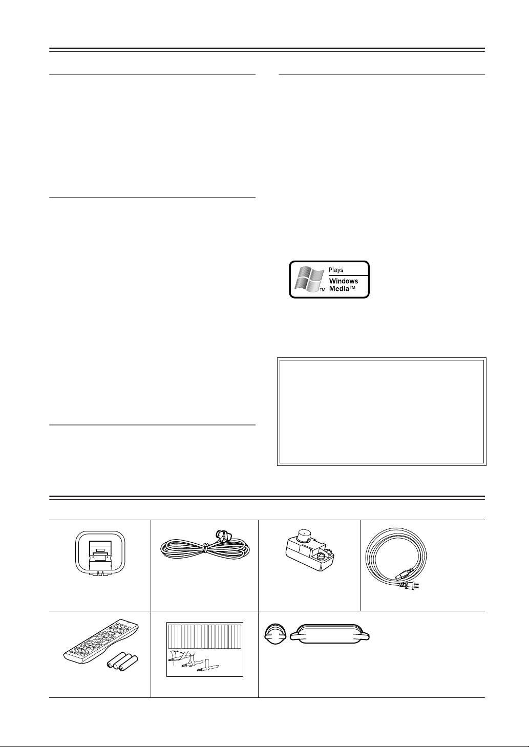
Supplied Accessories
Make sure you have the following accessories:
Indoor FM antenna
AM loop antenna
Remote controller &
three batteries (AA/R6)
*In catalogs and on packaging, the letter added to the end of the product name indicates the color of the DTR-7.4. Specifications and operation are the
same regardless of color.
6
(connector type varies
from country to country
Left
Left
Left
Left
Front
Front
Front
Right
Zone 2
Zone 2
/
/
SP-B
SP-B
Zone 2
Zone 2
/
/
Front
Left
SP-B
Left
Front
Right
Front
Left
SP-B
Left
1
Speaker Cable
Speaker cable labels
The power
cord may differ depending on the
region.
75/300 ohm antenna
adapter
(Australian model only)
Left
Left
Left
Left
Left
Front
Right
Right
Zone 2
/
SP-B
Zone 2
/
Front
Right
SP-B
Right
Left
Right
Right
Right
Zone 2
/
Surround
Surround
Surround
Surround
SP-B
Zone 2
/
Surround
Left
Surround
Right
Surround
Left
Surround
Right
SP-B
Right
2
3
Right
Right
Right
Right
Center
Center
Zone 2
Zone 2
Zone 2
Zone 2
Surround Back
Surround Back
Surround Back
Surround Back
Zone 2
Right
Zone 2
Left
Center
Zone 2
Right
Zone 2
Left
Surround Back
Right
Surround Back
Left
Center
Surround Back
Right
Surround Back
Left
Protective caps
For digital jack × 1
For analog jack × 1
Power cord
Protective caps for the
Video 5 jacks on the front of
the DTR-7.4. Be sure to
always attach the protective
caps when you are not connecting a device to the
Video 5 jacks.
Page 7
Before Using the DTR-7.4
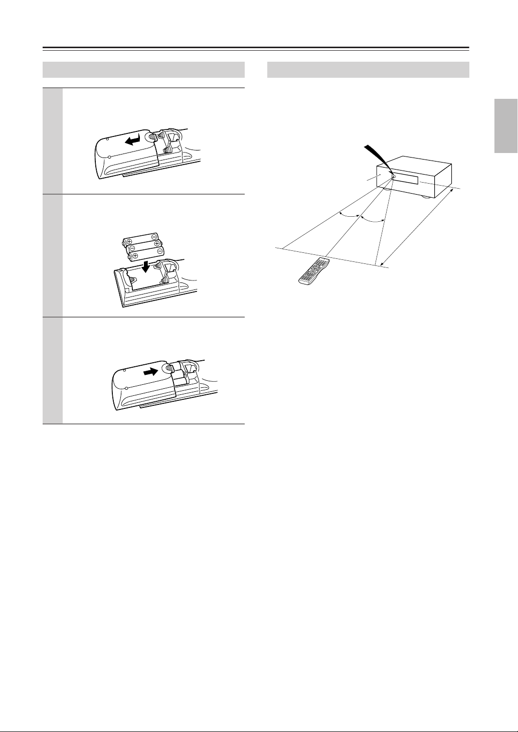
Installing the Batteries
To open the battery compartment, press
1
the small hollow and slide off the cover.
Insert the two supplied batteries (AA/R6)
2
in accordance with the polarity diagram
inside the battery compartment.
Put the cover onto the remote controller
3
and slide it shut.
Notes:
• The supplied batteries should last for about six
months, although this will vary with usage.
• If the remote controller doesn’t work reliably, try
replacing both batteries.
• Don’t mix new and old batteries, or different types of
batteries.
• If you intend not to use the remote controller for a
long time, remove the batteries to prevent possible
leakage and corrosion.
• Dead batteries should be removed as soon as possible
to prevent possible leakage and corrosion.
Using the Remote Controller
To use the remote controller, point it at the DTR-7.4’s
remote control sensor, as shown below. The DTR-7.4’s
Standby indicator flashes while a signal is being
received from the remote controller.
Remote control sensor
DTR-7.4
Standby indicator
30˚
30˚
Approx. 16 ft. (5 m)
Notes:
• The remote controller may not work reliably if the
DTR-7.4 is subjected to bright light, such as direct
sunlight or inverter-type fluorescent lights. Keep this
in mind when installing the DTR-7.4.
• If another remote controller of the same type is used
in the same room, or the DTR-7.4 is installed close to
equipment that uses infrared rays, the remote controller may not work reliably.
• Don’t put anything, such as a book, on the remote
controller, because the buttons may be pressed inadvertently, thereby draining the batteries.
• The remote controller may not work reliably if the
DTR-7.4 is installed in a rack behind colored glass
doors. Keep this in mind when installing the
DTR-7.4.
• The remote controller will not work if there’s an
obstacle between it and the DTR-7.4’s remote control
sensor.
• You can set the transmission signal format to infrared
(IR), or radio frequency (RF) for use with the
optional RF Receiver. This is useful when, for example, the DTR-7.4 is installed in a rack or is not in line
of sight of the remote controller.
Before Using
7
Page 8
Index Parts and Facilities
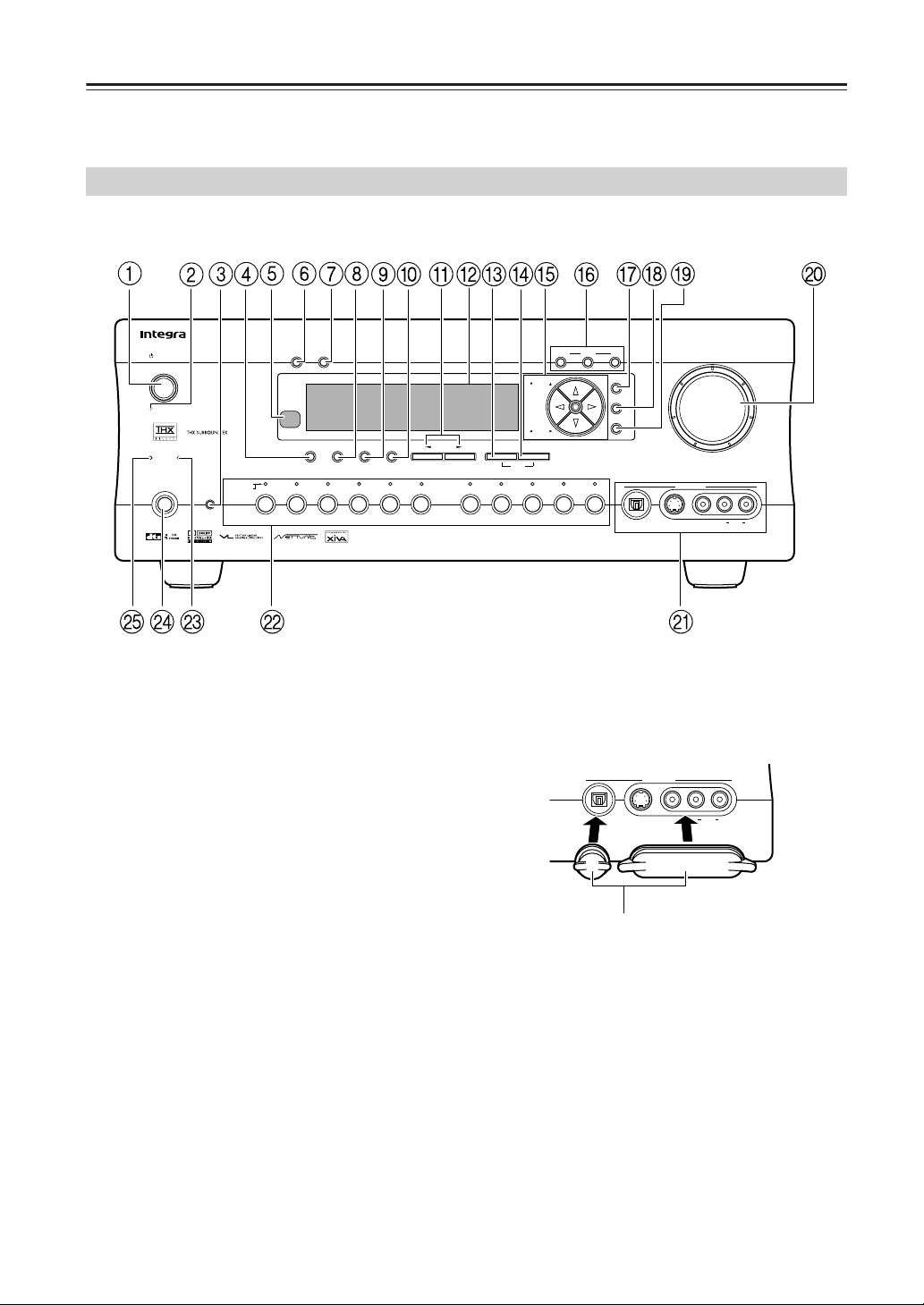
Here is an explanation of the controls and displays on the front panel of the DTR-7.4.
The specifications for your model may differ due to regional requirements.
Front Panels
Standby/On
Standby
Phones
DimmerDisplay
Tape
Memory FM Mode
Tuner Phono Net AudioCD
StereoDirect / Pure Audio
Video 2
Surround THX
Video 3
Video 4 Video 5
VCR 2
UpsamplingPure Audio
()
Zone 2
GRN
()
Rec
RED
DVD
Audio
Selector
Video 1
VCR 1
DSP
Rec Out
Zone 2 Of
f
Tuning
Preset
Clear
Setup
Enter
Return
A-FO RM Listening Mode Memory
Digital
S Video
Video 5 Input
Master Volume
Video L R
Audio
DTR-7.4
Protective caps
Protective caps are provided for the Video 5 jacks. Be
sure to always attach the protective caps when you are
not connecting a device to the Video 5 jacks.
Video 5 Input
Digital
S Video
Video L R
Audio
DTR-7.4
Protective caps
8
Page 9

Index Parts and Facilities —Continued
For further operational instructions, see the pages indicated in brackets [ ].
1
Standby/On button [27]
This button is used to set the DTR-7.4 to On or
Standby. In the standby state, the display is turned off
and the DTR-7.4 cannot be operated.
Standby indicator [7, 27]
2
Lights when the DTR-7.4 is in the standby state and
when a signal is received from the remote controller.
3
Audio Selector button [43, 65]
Press to select the type of audio input signal.
Direct/Pure Audio button [46, 65]
4
Press to switch between the direct and pure audio
listening modes.
5
Remote control sensor [7]
Display button [42]
6
Press to display information about the current input
source signal. Each time you press the Display button, the screen changes to show you different information concerning the input signal.
7
Dimmer button [41]
Press to set the brightness of the front display. There are
three settings available: normal, dark, and very dark.
The brightness of the front display can also be
changed using the remote controller.
Stereo button [46]
8
Selects for the stereo listening mode.
Surround button [46]
9
Selects for the Dolby Pro Logic II, DTS Neo:6,
Dolby Digital, or DTS listening modes.
THX button [47]
0
Selects for the THX listening mode.
DSP / buttons [47]
A
Switches to the DSP (Digital Signal Processing) modes.
Front display
B
Memory button [49]
C
Press to assign the radio station to which you are
currently tuned to a preset channel or press to delete
a previously preset station.
FM Mode button [48, 49]
D
Press to change the stereo mode from AUTO to
MONO and vice versa. Each time this button is
pressed, the AUTO indication turns on and off indicating the current mode. If you are listening to an FM
radio station in stereo and the sound cuts out or there is
a great deal of noise, switch from AUTO to MONO.
E
Tuning / buttons [48]
These buttons used to tune into radio stations and to
select items on the onscreen setup menus (OSD).
Preset / buttons [49]
These buttons are used to select radio presets and to
select items on the onscreen setup menus (OSD).
F
Rec Out button [50, 51]
This button is used to select the input source that
you want to record via the REC OUTs (i.e., TAPE
OUT, VIDEO 1 OUT, VIEDO 2 OUT).
Zone 2 button [68]
This button is used to select the input source for Zone
2.
Off button [68]
This button is used to turn off the REC OUTs (i.e.,
TAPE OUT, VIDEO 1 OUT, VIDEO 2 OUT) or
Zone 2.
Setup button [29]
G
Press to enter the Setup Menu. The OSD Menu will
appear on the TV monitor as well as the front display on the DTR-7.4.
H
Enter button [29]
Press to display the screen for the item that is
selected in the Setup Menu.
I
Return button [29]
In the Setup Menu, press to go back one level. If
pressed while at the Main Menu, you will exit the
Setup Menu.
Master Volume dial [40, 65]
J
Use to control the volume in the main zone. The volume for the remote zone (Zone 2) is independent.
Video 5 Input terminals [23]
K
For connecting a video camera or game device.
Input source buttons and indicators (DVD,
L
Video 1–5, Tape, Tuner, Phono, CD, and Net
Audio) [35, 36, 40]
Press these buttons to select the input source for the
main zone.
To select the input source for the remote zone (Zone
2) or recording out (REC OUT), first press the Zone
2 or Rec Out button, and then press the desired
input source button. The input channel with its indicator lit
red
is output to REC OUT and the one with
its indicator lit
Upsampling indicator [55]
M
Lights during upsampling. This function is available
when the input source is Analog/PCM and the listening mode is set to the stereo or surround mode.
Phones jack [40]
N
This is a standard stereo jack for connecting stereo
headphones.
O
Pure Audio indicator [46]
Lights during pure audio playback.
green
is output to ZONE 2.
Facilities and Connections
9
Page 10
Index Parts and Facilities —Continued
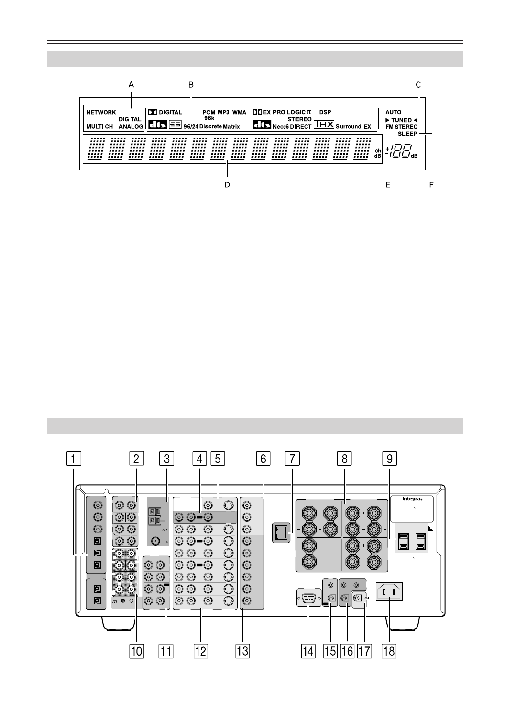
Front Panel Display
A
Input signal path indicators
Shows from which terminal the input signal is coming.
B Listening mode or digital input format
indicators
One of these indicators lights to show the format of
the current input source. In addition, one of the listening mode indicators lights to indicate the current
listening mode.
C Tuning indicators
AUTO indicator
Lights when receiving FM broadcasts in the stereo
mode. Turns off when placed into the monaural
mode.
TUNED indicator
Lights when a radio station is being received.
Rear Panel
FM STEREO indicator
Lights when an FM broadcast station is being
received in stereo. Turns off when placed into the
monaural mode.
D Multi function display
During normal operation, shows the current input
source and volume. When the FM or AM input is
selected, shows the frequency and preset number.
When the Display button is pressed, shows the listening mode and input source format. However,
does not show the source format when the FM or
AM source is selected.
E Volume display
Shows the volume level.
F SLEEP indicator
Lights when the sleep timer is turned on.
10
DIGITAL
PRE OUT
IN
COAX
FRONT
1
SUB
2
SURR
3
SURR
BACK/
OPT
ZONE 2
1
FRONT
2
R
SUB
3
SURR
DIGITAL
OUT
OPT
1
SURR
BACK
2
GND
ANTENNA
L
R
CENTER
AM
R
L
R
L
MULTI CH
INPUT
L
CENTER
FM
75
AUDIO
L
R
PHONO
IN
CD
IN
OUT
TAPE
IN
L
R
AUDIO
VIDEO
AUDIO
R
R
AUDIO
MONITOR
L
OUT
IN
OUT
VIDEO 1
IN
OUT
VIDEO 2
IN
VIDEO 3
IN
VIDEO 4
IN
L
VIDEO
ZONE 2
COMPONENT
S VIDEO
VIDEO
OUT
DVD
S VIDEO
OUTPUT
Y
P
PR
INPUT 1
Y
P
PR
INPUT 2
Y
P
PR
B
ETHERNET
(Net -Tune)
B
B
CENTER
SPEAKER
FRONT SPEAKERS
RL
I R
IN
RS232
OUT
R
A
B
SURR SPEAKERS
R
ZONE 2
12 V
TRIGGER OUT
REMOTE
CONTROL
SURR
BACK/
ZONE 2
SPEAKERS
L
AC INLET
AV RECEIVER
MODEL NO. DTR
:
RATING
AC 120 V 60 Hz 8.1 A
AC OUTLETS
AC 120 V 60 Hz
SWITCHED
TOTAL 120W 1A MAX.
-
7.4
L
Page 11

Index Parts and Facilities—Continued
For more information regarding connection procedures,
see pages indicated in brackets [ ].
1 DIGITAL IN/OUT [21-24]
These jacks are for connecting components with
digital input and output capabilities. To connect a
CD player, see page 23; to connect an MD or CD
recorder, see page 24; to connect a DAT deck, see
page 24; to connect a DVD player, see page 21; to
connect a DVD recorder, see page 22; and to connect a digital satellite tuner, see page 22.
2 PRE OUT [18, 25, 66]
To use the DTR-7.4 as a preamplifier, connect a
power amplifier to this jack.
3 ANTENNA [14]
These jacks are for connecting the FM indoor
antenna and the AM loop antenna that are supplied
with the DTR-7.4.
4 ZONE 2 OUT [66]
This jack is for connecting the component that will
be used in the remote zone (Zone 2).
5 MONITOR OUT VIDEO/S VIDEO [20]
These jacks are for connecting to the video input
jacks on television monitors or projectors.
6 COMPONENT VIDEO OUTPUT [20]
These jacks are for connecting to the component
video input jacks on television monitors or projectors.
7 ETHERNET (Net-Tune) [73]
This connector is for connecting to an Ethernet network.
8 SPEAKERS [18, 66]
These terminals are for connecting the speakers.
9 AC OUTLETS [24]
This AC outlet is provided to plug in the power cord
from another component. The shape and number of
the AC outlet depend on the shipping destination.
0 MULTI CH INPUT [64]
This connector is for connecting components with a
multichannel output.
A PHONO/CD/TAPE AUDIO IN/OUT [23, 24]
These connectors are for connecting to the audio
input and output jacks on audio components. To
connect a turntable, see page 23; to connect a CD
player, see page 23; and to connect a cassette tape
deck, MD recorder, or CD recorder, see page 24.
B DVD/VIDEO1-4 IN/OUT [21, 22]
These connectors are for connecting to the video
input and output jacks on video components. To
connect a DVD player, see page 21; to connect a
DVD recorder, see page 22; to connect a VCR, see
page 21; and to connect a digital satellite tuner, see
page 22.
C COMPONENT VIDEO INPUT1/2 [21, 22]
These connectors are for connecting to the component video outputs of video components that have
them. To connect a DVD player, see page 21; to
connect a DVD recorder, see page 22; and to connect a digital satellite tuner, see page 22.
D RS 232
This port is for connecting the DTR-7.4 to home
automation and external controllers.
E IR IN/OUT [69]
These connectors are for connecting the remote sensor of a multi-room kit (sold separately).
F 12V TRIGGER OUT ZONE 2 A/B [71]
These connectors are used to connect to the 12V
TRIGGER IN terminal of a component.
G [26]
This jack is for connecting other Integra/Onkyo
components equipped with the same terminal.
The audio connection cables must also be connected.
H AC INLET [27]
This connector is for connecting the supplied power
cord.
Facilities and Connections
11
Page 12
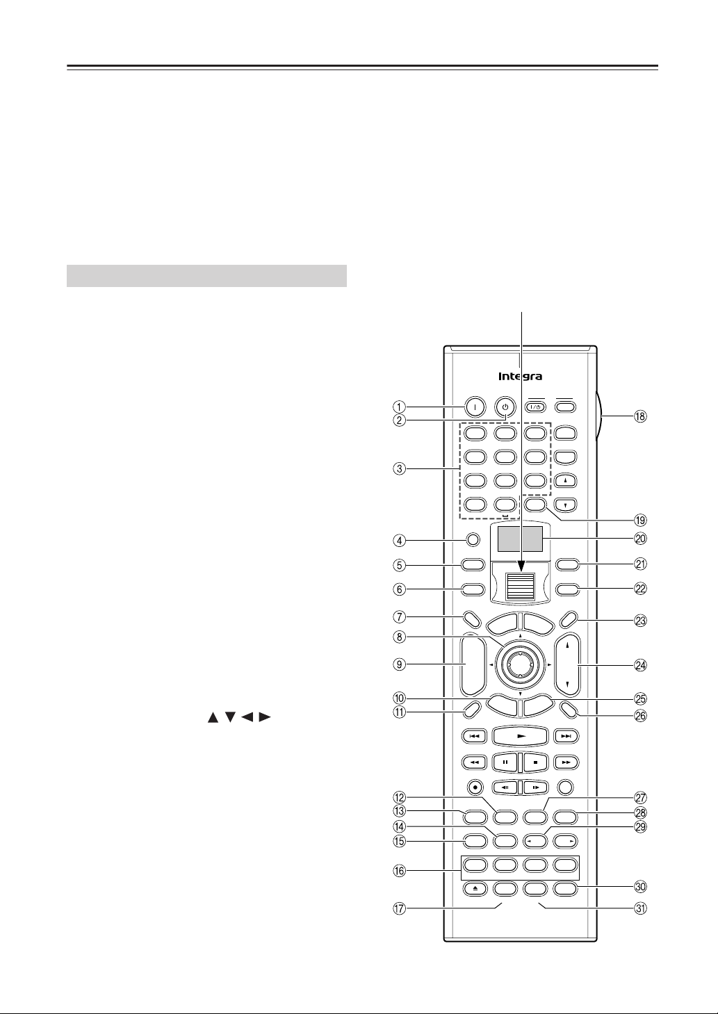
Remote Controller
The DTR-7.4’s remote controller is a multipurpose
device that can be used to control not just the DTR-7.4
but your other AV components as well. This section
explains how its various operating modes can be used to
control the DTR-7.4. When you use the Net-Tune mode,
see page 74 for details. See page 84 for information on
using the remote controller to control Onkyo components and TVs, VCRs, and AV components made by
other manufacturers.
For detailed information, refer to the pages in parenthesis.
Amp Mode
Amp mode is used to control the DTR-7.4. To select
Amp mode, press the scroll wheel. “AMP” appears
on the display.
Note:
While neither the Input button nor Mode button is illuminated, rolling the scroll wheel changes the input
source and remote controller mode simultaneously.
1 On button [27]
This button is used to turn on the DTR-7.4.
2 Standby button [27]
This button is used to set the DTR-7.4 to Standby.
3 Number/letter buttons [48, 49]
These buttons are used to enter numbers and letters.
4 Custom button [94-98]
This button is used to access various settings that
you can use to customize the operation of the
remote controller.
5 Macro button [95]
This button is used with the Macro function.
6 Mode button
This button is used with the scroll wheel to select
the remote controller modes.
7 Dimmer button [41]
This button is used to adjust the display brightness.
8 Up/Down/Left/Right /// & Enter
buttons
These buttons are used to select items on the
onscreen setup menus (OSD). The Enter button is
also used to enter names and to confirm settings.
9 CH/Disc +/– button [49)
This button is used to select radio presets.
0 Return/Exit button
This button is used to return to the previously displayed onscreen setup menu (OSD).
A Display button [42]
This button is used to display various information
about the currently selected input source.
B THX button [47]
This button is used to select the THX listening
modes.
C Surround button [46]
This button is used to select the Dolby and DTS listening modes.
D Direct button [46, 65]
This button is used to select the Direct listening
mode.
E Pure A button [46, 65]
This button is used to select the Pure Audio listening mode.
Scroll wheel
On Standby
123
@. - ' / ABC DEF
456
GHI JKL MNO
789
PQRS TUV WXYZ
+
10 0
--/---
Custom
Macro
Dimmer
T V
Input
M
p
o
T
+
CH
Disc
-
E
R
e
t
u
Display
Rec
Surround
THX
Pure A
Direct
Test Tone
CH SEL
Album Ar tist GenrePlaylist
Audio SEL
Caps Delete
RC
Clear
Direct Tuning
u
M
n
e
A
u
d
Enter
x
i
t
G
r
n
S
Step / Slow
AngleSubtitleAudio
All CH ST
Level
L Night
Language Loca t ion
-
550M
T V
TV CH
TV VOL
e
n
u
i
o
A
D
J
e
d
i
u
p
u
t
e
Random
Last Memory
Stereo
MemorySearchA-BRepeat
DSP DSP
-
Level
Re-EQ
Input
+
-
Zone 2
InputMode
VOL
Muting
Sleep
+
12
Page 13

Remote Controller—Continued
F Test Tone, CH SEL, Level– & Level+ buttons
[35]
These buttons are used to adjust the level of each
speaker individually. These functions can be set
only with the remote controller. The Level– and
Level+ buttons are also used to adjust the volume in
Zone 2.
G Audio SEL button [43]
This button is used to select the audio input signal
format: analog, digital, or multichannel.
H LIGHT button
This button is used to turn on or off the remote controller’s illuminated buttons.
I Direct Tuning button [48]
This button is used with the number buttons to
select a radio station by entering its frequency. Press
this button first, and then use the number buttons to
enter the frequency.
J Display
The top line of this LCD display shows the name of
the currently selected input source. The bottom line
shows the currently selected remote controller
mode.
K Zone 2 button [68]
This button is used when you want to set the volume
and input source for Zone 2.
L Input button [40]
This button is used to select the input source. Press
this button first, and then roll the scroll wheel until
the name of the input source appears on the display.
M Sleep button [41]
This button is used to set the Sleep function. This
function can be set only with the remote controller.
N VOL button [40, 65]
This button is used to set the volume of the
DTR-7.4.
O Setup/Guide button [29]
This button is used to access the onscreen setup
menus (OSD) that appear on the TV.
P Muting button [40]
This button is used to mute the DTR-7.4. This function can be set only with the remote controller.
Q All CH ST button [47]
This button is used to select the All Ch Stereo listening mode.
R Stereo button [46]
This button is used to select the Stereo listening
mode.
S DSP/DSP buttons [47]
These buttons are used to select the DSP (digital
signal processor) listening modes.
T Re-EQ button [55]
This button is used to turn on and off the Re-EQ
function.
U L Night button [55]
This button is used to set the Late Night function.
Facilities and Connections
13
Page 14
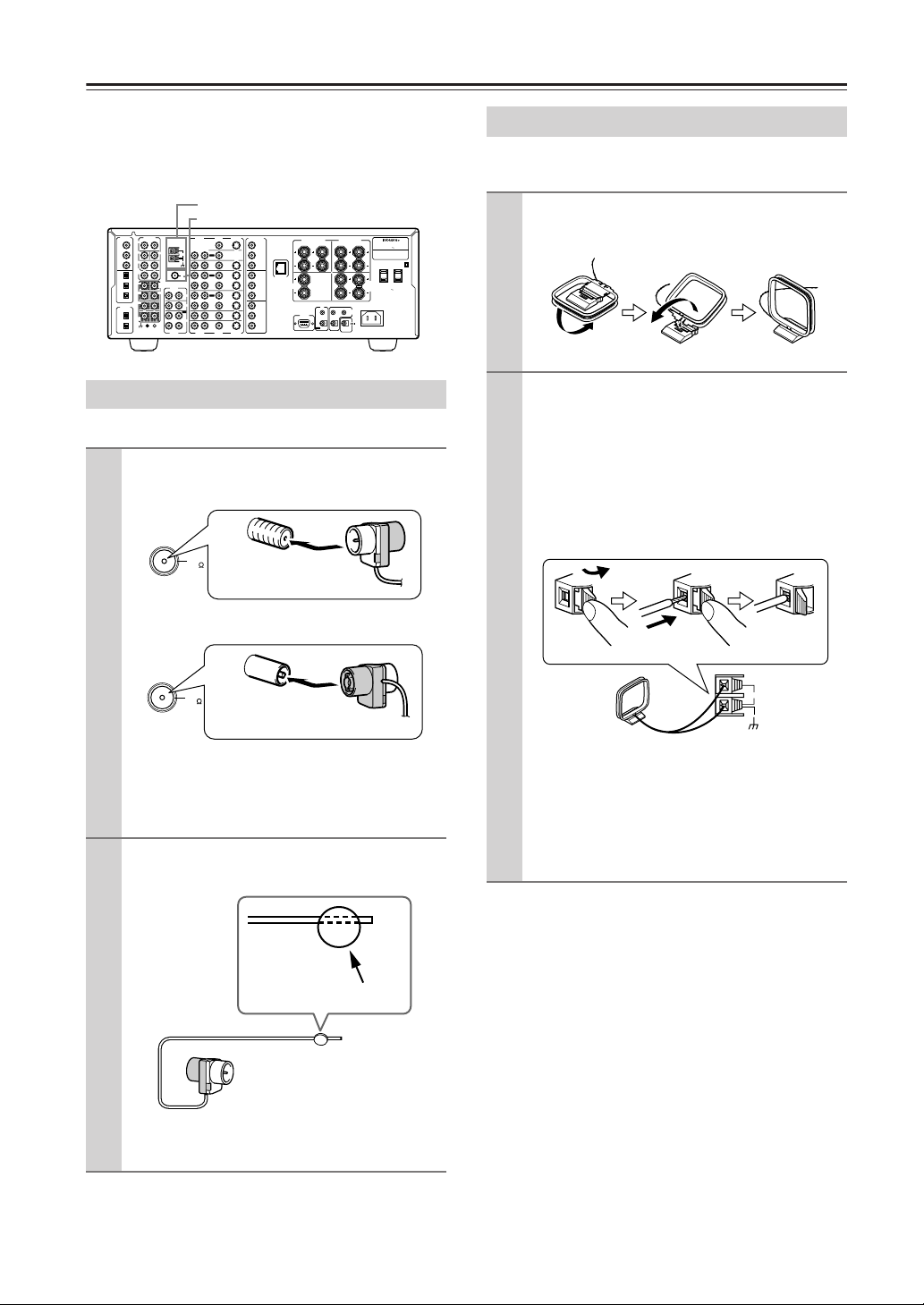
Connecting Antenna
This chapter explains how to connect the supplied
indoor FM antenna and AM loop antenna, and how to
connect commercially available outdoor FM and AM
antennas.
AM antenna push terminals
FM antenna connector
DIGITAL
PRE OUT
IN
ANTENNA
L
R
COAX
FRONT
1
SUB
CENTER
2
3
OPT
1
2
3
DIGITAL
OUT
OPT
1
2
AM
SURR
SURR
R
L
BACK/
ZONE 2
FM
75
FRONT
MULTICH
INPUT
AUDIO
R
L
L
R
SUB
CENTER
PHONO
IN
SURR
CD
IN
R
L
OUT
SURR
BACK
TAPE
IN
GND
L
R
AUDIO
COMPONENT
VIDEO
S VIDEO
AUDIO
R
R
AUDIO
VIDEO
FRONT SPEAKERS
CENTER
SPEAKER
RL
I R
IN
RS232
OUT
B
R
A
SURR SPEAKERS
R
ZONE 2
REMOTE
CONTROL
12 V
TRIGGER OUT
AV RECEIVER
L
-
MODEL NO. DTR
7.4
:
RATING
AC 120 V 60 Hz 8.1 A
AC OUTLETS
SURR
BACK/
ZONE 2
AC 120 V 60 Hz
SPEAKERS
SWITCHED
TOTAL 120W 1A MAX.
L
AC INLET
OUTPUT
MONITOR
OUT
L
L
Y
ZONE 2
B
P
OUT
DVD
IN
PR
INPUT 1
Y
OUT
IN
OUT
IN
IN
IN
VIDEO
ETHERNET
(Net-Tune)
VIDEO 1
P
B
PR
VIDEO 2
INPUT 2
Y
VIDEO 3
P
B
VIDEO 4
PR
S VIDEO
Connecting the Indoor FM Antenna
The supplied indoor FM antenna is for indoor use only.
Attach the FM antenna, as shown.
1
■ USA and Canadian Model
FM
75
Insert the plug fully
into the socket.
■ Australian Models
Connecting the AM Loop Antenna
The supplied indoor AM loop antenna is for indoor use
only.
Assemble the AM loop antenna, inserting
1
the tabs into the base, as shown.
Connect both wires of the AM loop
2
antenna to the AM push terminals, as
shown.
(The antenna’s wires are not polarity sensitive, so
they can be connected in either terminal.)
Make sure that the wires are attached securely
and that the push terminals are gripping the bare
wires, not the insulation.
Push
Insert wire
Release
FM
75
Insert the plug fully
into the socket
Once your DTR-7.4 is ready for use, you’ll need
to tune into an FM radio station and adjust the
position of the FM antenna to achieve the best
possible reception.
Use thumbtacks or something similar to
2
fix the FM antenna into position.
Thumbtacks, etc.
Caution: Be careful that you don’t injure yourself when using thumbtacks.
If you cannot achieve good reception with the supplied
indoor FM antenna, try using a commercially available
outdoor FM antenna instead (See page 15).
AM
Once your DTR-7.4 is ready for use, you’ll need
to tune into an AM radio station and adjust the
position of the AM antenna to achieve the best
possible reception. Keep the antenna as far away
as possible from your DTR-7.4, TV, speaker
cables, and power cords.
If you cannot achieve good reception with the supplied
indoor AM loop antenna, try using a commercially
available outdoor AM antenna (See page 15).
14
Page 15
Connecting Antenna—Continued
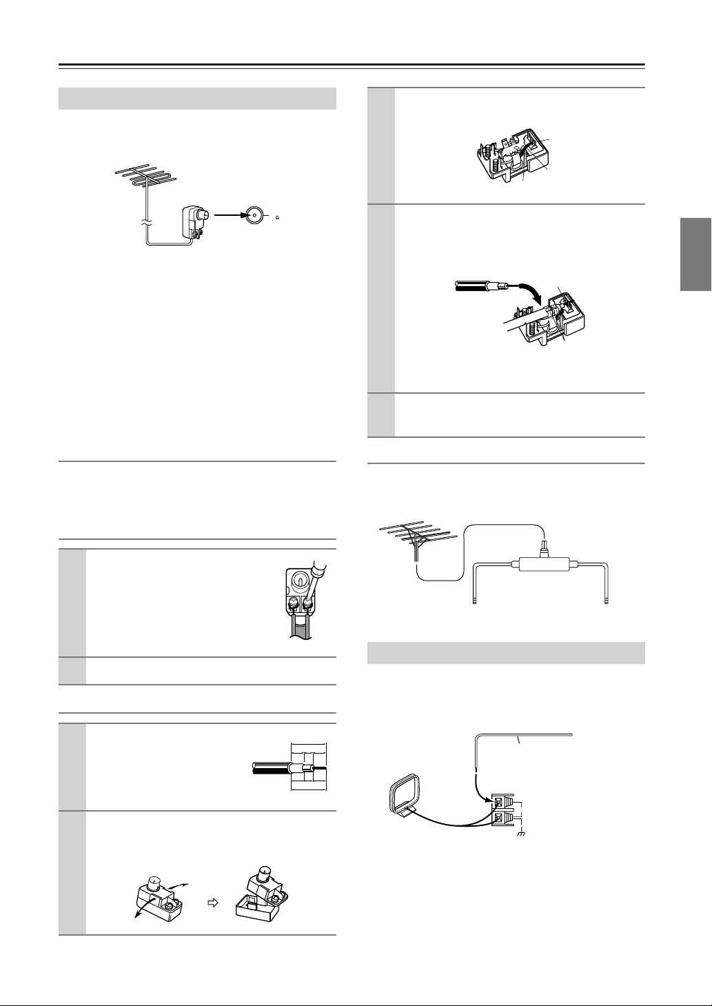
Connecting an Outdoor FM Antenna
If you cannot achieve good reception with the supplied
indoor FM antenna, try using a commercially available
outdoor FM antenna instead.
FM
75
Notes:
• Outdoor FM antennas work best outside, but usable results
can sometimes be obtained when installed in an attic or loft.
• For best results, install the outdoor FM antenna well away
for tall buildings, preferably with a clear line of sight to your
local FM transmitter.
• Outdoor antennas should be located away from possible
noise sources, such as neon signs, busy roads, etc.
• For safety reasons, outdoor antennas should be situated well
away from power lines and other high-voltage equipment.
• Outdoor antennas must be grounded in accordance with local
regulations to prevent electric shock hazards.
Using the 75/300 ohm Antenna Adapter
(Australian model only)
The 75/300 ohm antenna adapter can be used to connect
an FM antenna using either 75 ohm coaxial cable or
300 ohm twin-core flat cable.
Connecting 300 ohm Flat Cable
Move the small wire inside the adapter
3
from position A to position B, as shown.
Position A
Wire
Position B
Insert the central conductor (1), as
4
shown, and use a small pair of pliers to
clamp the shielding and outer insulation
sections of the cable (
✦
✦
✦
✦
✦
✦
✦
✦
✦
✦
✦
2), as shown.
1
✦
✦
✦
✦
2
Make sure the shielding is not touching the central conductor.
Refit the adapter’s cover, and then plug
5
the adapter into the 75 Ω socket.
Using a TV/FM Antenna Splitter
It’s best not to use the same antenna for both FM and TV
reception, as this can cause interference problems. If circumstances demand it, use a TV/FM antenna splitter, as shown.
Facilities and Connections
Using a screwdriver, loosen
1
the two screws on the adapter,
wrap the bare wires around the
screws, and then retighten
them, as shown.
Plug the adapter into the 75 Ω socket.
2
Connecting 75 ohm Coaxial Cable
Strip and prepare the
1
75 ohm coaxial cable, as
shown.
Using your fingernails or a small screw-
2
driver, lever the adapter’s tabs outward
and remove the cover, as shown.
15 mm
6mm3mm6
✦
✦
✦
✦
✦
✦
✦
✦
✦
✦
✦
1/4" 1/8" 1/4"
5/8"
TV/FM antenna splitter
To TV (or VCR)To AV receiver
Connecting an Outdoor AM Antenna
If good reception cannot be achieved using the supplied
AM loop antenna, an outdoor AM antenna can be used
in addition to the loop antenna, as shown.
Outdoor antenna (aerial)
mm
AM loop antenna
Outdoor AM antennas work best when installed outside
horizontally, but good results can sometimes be obtained
indoors by mounting horizontally above a window. Note
that the AM loop antenna should be left connected.
Outdoor antennas must be grounded in accordance with
local regulations to prevent electric shock hazards.
Insulated antenna cable
AM
15
Page 16
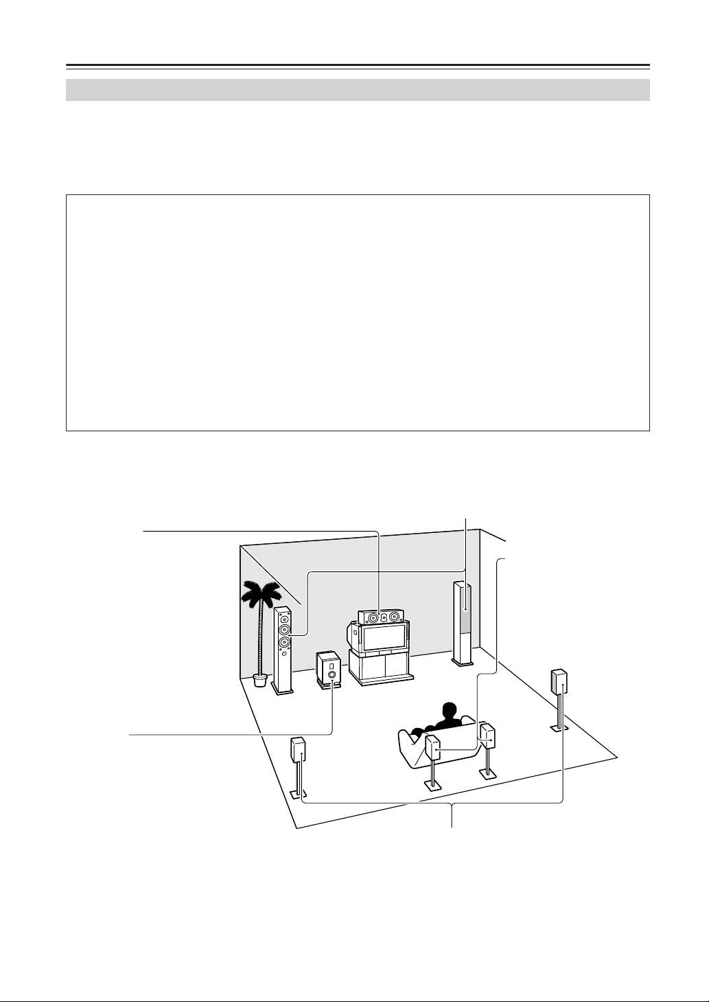
About Home Theater
Enjoying Home Theater
The DTR-7.4 has many excellent features to recreate a clear three-dimensional sound image and lively sound movement.
This enables you to easily enjoy rich sound effects just like you were in a theater or concert hall at home.
For the DTR-7.4, We recommend you to use the THX-certified THX speaker system for THX Surround EX playback.
When playing a DVD, you can enjoy sound effects provided by DTS, Dolby Digital or THX, depending on recording
formats. In addition, you can enjoy Integra’s proprietary DSP surround playback for TV or digital satellite broadcasts.
How to use speakers
When you have two speakers, they are used for front left and right speakers (2 channel playback).
When you have three speakers, they are used for front left, front right and center speakers (3 channel surround
playback).
When you have four speakers, they are used for front left, front right, surround left, and surround right speakers (4
channel surround playback).
When you have five speakers, they are used for front left, front right, center, surround left and surround right
speakers (5 channel surround playback).
When you have six speakers, they are used for front left, front right, center, surround left, surround right and
surround back speakers (6 channel surround playback).
When you have seven speakers, they are used for front left, front right, center, surround left, surround right,
surround back left, and surround back right speakers (7 channel surround playback).
No matter how many speakers you use, a subwoofer can be used to produce powerful and heavy bass sound (0.1
channel playback).
Front left and right speakers
Output overall sound. They play the most important role in a home theater system, by creating basic sound
images and fields.
Place the front speakers in front of the listener so that they point to the listener’s ears in the listening position
for music and movies. Ideal speaker placement is so that they are located symmetrically.
Center speaker
Complements the sound effects from
front left and right speakers to enrich
and clear the sound image and movement. In movies, an actor's speech
comes mainly from the center
speaker.
Place the center speaker as close as
possible to the TV or monitor, pointing it towards the listener’s ears.
Also, keep the center speaker’s
height at the same level as the front
left and right speakers.
Subwoofer
Outputs only bass sounds to
enhance and complement bass
sound effects. Place the subwoofer either at the front corner
of the room or at a position 1/3
from either front corner of the
room.
Surround left and right speakers
Enhance the sensation of being at a live performance by giving three-dimensional
sound movement to the sound effects. Place the surround speakers at the side of
the listener or at a position diagonally from the listener. Ideally, speakers should
be placed symmetrically.
Surround back speakers
Enhance the sound space representation with surround channel
signals. Recreating sound
movement effects and sound
fields behind the listener gives a
more realistic experience.
• For optimum surround playback, set the distance between the listener and the speakers so that the time it takes the
sound to reach the listener is constant. Also, you need to set each speaker volume level individually in order to balance
the volume level between speakers (See pages 32 and 35).
16
Page 17
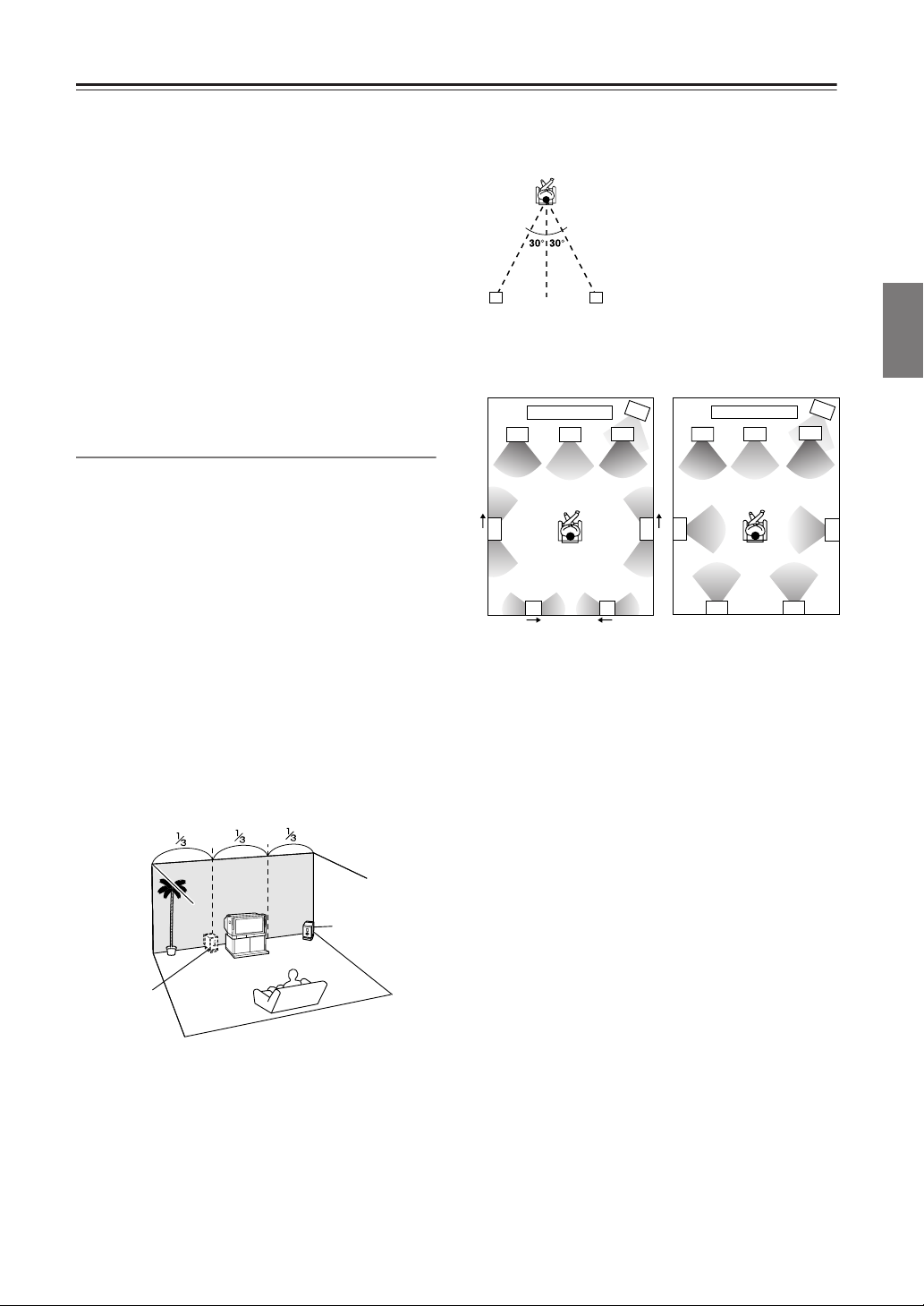
Speaker Placement
Before connecting the speakers, it is very important to
place them properly to create the optimum sound space
for your listening pleasure. During placement and
connection, be sure to refer to the manuals and
instructions that came with the speakers. Furthermore,
be aware that for surround playback, the configuration
and placement of your speakers are both very important.
Ideal speaker placement varies depending on the size of
your room and the wall coverings. Here, only typical
examples of speaker placement and recommendations
are shown.
In order to create the optimum conditions for the best
sound quality, be sure to place all the speakers so that the
greatest difference between the distances of each
speaker to the listening position is less than 20 feet (6
meters).
Important Points Regarding Speaker Placement
Front left and right speakers and center speaker
• Place these three speakers all at the same height.
• Place each speaker so that it is aimed at the location of
the listener’s ears when at the listening position.
• Place the right and left peakers at equal distances on
either side of the listening point.
Surround left and right speakers
• Place these speakers so that their height is 3 feet (1
meter) higher than that of the listener’s ears.
Subwoofer
When bass sound is reproduced, its volume and quality
greatly depend on subwoofer placement. Those
characteristics also depend on the shape of your listening
room as well as your listening point. Generally, good
bass sound is obtained when the subwoofer is placed in
the corner of the room or at a point 1/3 the length of the
room.
Corner
Surround back speakers
• Place these speakers so that
their height is 3 feet (1 meter)
higher than that of the listener’s
10
ears.
• When using surround back left
and right speakers, place them
behind the listener so that the
angles between the lines from
8 9
each speaker to the listener and
a line straight back from the
listener are about 30 degrees.
Layout with dipolar
speakers
1
3
4
67
10
8 9
1 TV or screen
2 Subwoofer
3 Front left speaker
4 Center speaker
5 Front right speaker
6 Surround left speaker
7 Surround right
speaker
5
Layout with monopolar
speakers
2
3
6
10
89
8 Surround back left
speaker
9 Surround back right
speaker
10 Listening position
1
4
2
5
Most dipoles are marked with an arrow to indicate how
they should be oriented in the room. For correct
acoustical phasing in the room, dipolar surround
speakers should be placed so that their arrows point
forward toward the screen; and dipolar surround back
speakers should be placed so that their arrows point
toward each other.
7
Facilities and Connections
1/3 room
length
To optimize the subwoofer placement, we
recommend:
• Playing a movie or music source containing good
quality bass sound,
• Experimenting while changing subwoofer’s position
in the room, and
• Repositioning the subwoofer until you obtain the most
out of the bass sound while fixing the listening point.
17
Page 18
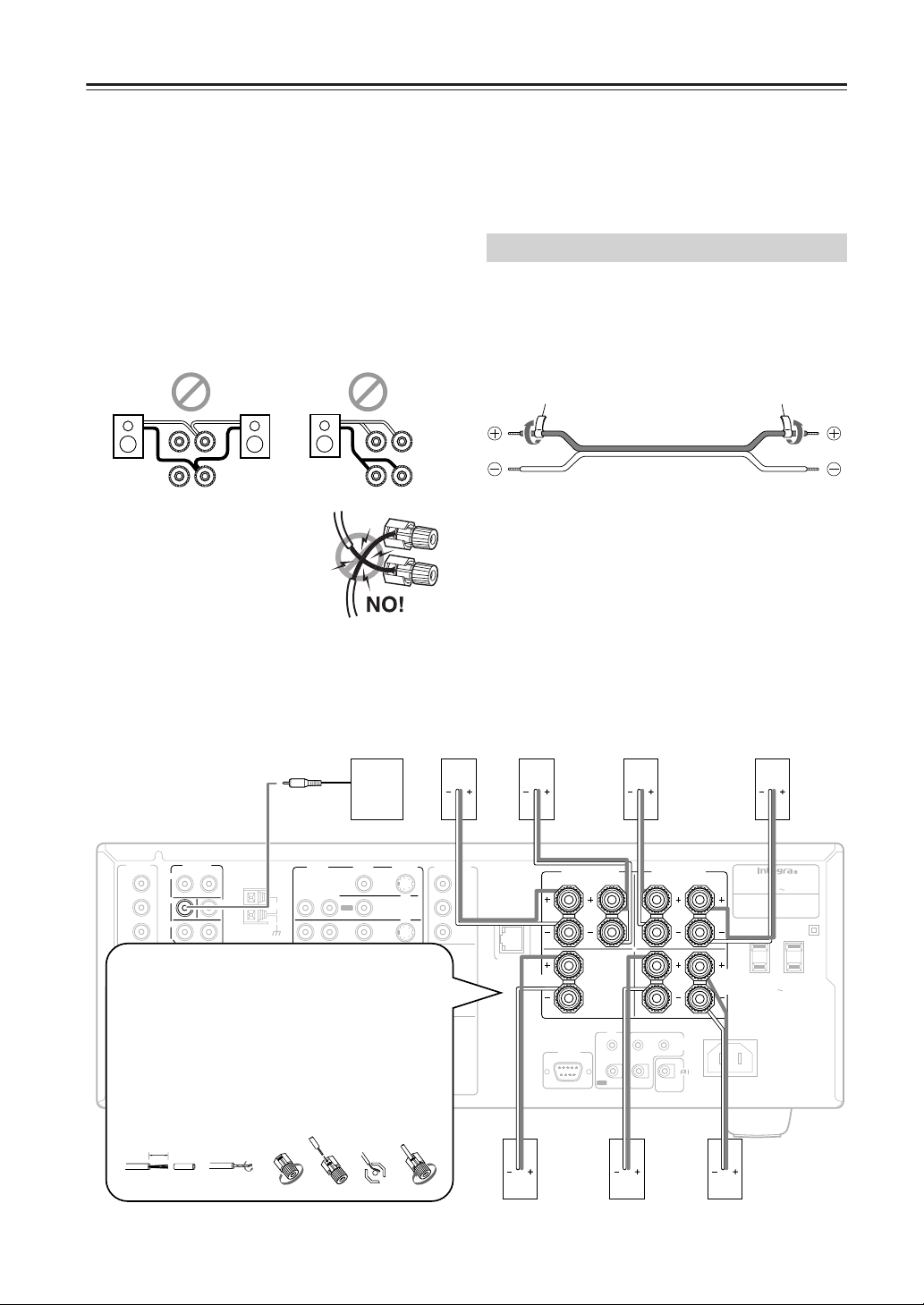
Connecting Speakers
After determining the layout of your speaker system, it
is now necessary to connect the speakers correctly to
your DTR-7.4.
You can also use banana plugs/connectors.
Caution:
Connect only speakers with an impedance between 4 and
16 Ω to the DTR-7.4. If the impedance of even one
speaker is between 4 and 6 Ω, be sure to set the speaker
impedance setting accordingly (See page 30).
Notes:
• Even if you are using only one speaker or listening to
monaural (mono) sound, never connect a single speaker
in parallel to both the right and left-channel terminals.
L
R
+
–
+
–
L
R
L
R
+
–
+
–
L
R
• To prevent damage to circuitry,
never short-circuit the positive (+)
and negative (–) speaker wire.
• Be sure to connect the positive and
negative cables for the speakers
properly. If they are mixed up, the
left and right signals will be reversed
and the audio will sound unnatural.
Use the PRE OUT
SUBWOOFER jack to
connect a subwoofer with a
built-in power amplifier. If
your subwoofer does not have
Subwoofer
Front
right
speaker
a built-in amplifier, connect an
amplifier to the PRE OUT
SUBWOOFER jack and the
subwoofer to the amplifier.
• Do not connect more than one speaker cable to one
speaker terminal. Doing so may damage the DTR-7.4.
• Connect either your surround back speakers or the
speakers you will be using in the remote zone (Zone
2) to the SURR BACK/ZONE 2 SPEAKERS
terminals (See page 66).
Using the Speaker Cable Labels
The positive speaker terminals on the DTR-7.4 are color
coded for easy identification. Attach the supplied
speaker labels to the speaker cables, and then match the
colors on the speaker cables to the corresponding
terminals.
Speaker cable label
The speaker channels are colored as follows:
Front left speaker (+): White
Front right speaker (+): Red
Center speaker (+): Green
Surround left speaker (+): Blue
Surround right speaker (+): Grey
Surround back/Zone 2 left speaker (+): Brown
Surround back/Zone 2 right speaker (+): Tan
Front
left
speaker
Surround
right
speaker
Speaker cable label
Surround
left
speaker
18
DIGITAL
COAX
1
2
3
OPT
1
Connecting the speaker cable
2
1. Strip away approx. 5/8 inch (15 mm) of the
3
DIGITAL
2. Twist the wire ends tightly together.
OPT
1
3. Unscrew the speaker terminal cap.
4. Insert the exposed wire end.
2
5. Screw down the speaker terminal cap.
PRE OUT
IN
R
FRONT
SUB
SURR
SURR
R
BACK/
ZONE 2
FRONT
R
SUB
wire insulation.
SURR
OUT
R
SURR
BACK
GND
5/8"
(15mm)
L
L
L
25341
CENTER
MULTI CH
INPUT
L
CENTER
ANTENNA
AUDIO
R
R
AUDIO
VIDEO
AUDIO
L
R
AM
FM
75
L
PHONO
IN
CD
IN
OUT
TAPE
IN
L
R
L
AUDIO
S VIDEO
MONITOR
OUT
ZONE 2
OUT
DVD
IN
OUT
VIDEO 1
IN
OUT
VIDEO 2
IN
VIDEO 3
IN
VIDEO 4
IN
VIDEO
S VIDEO
COMPONENT
VIDEO
OUTPUT
Y
P
B
PR
INPUT 1
Y
P
B
PR
INPUT 2
Y
P
B
PR
ETHERNET
(Net -Tune)
CENTER
SPEAKER
Center
speaker
RS232
FRONT SPEAKERS
RL
I R
IN
OUT
B
SURR SPEAKERS
R
R
A
ZONE 2
REMOTE
CONTROL
Surround
back
right
speaker
L
12 V
TRIGGER OUT
SURR
BACK/
ZONE 2
SPEAKERS
L
AC INLET
AV RECEIVER
MODEL NO. DTR
:
RATING
AC 120 V 60 Hz 8.1 A
AC OUTLETS
AC 120 V 60 Hz
SWITCHED
TOTAL 120W 1A MAX.
Surround
back left
speaker
-
7.4
Page 19
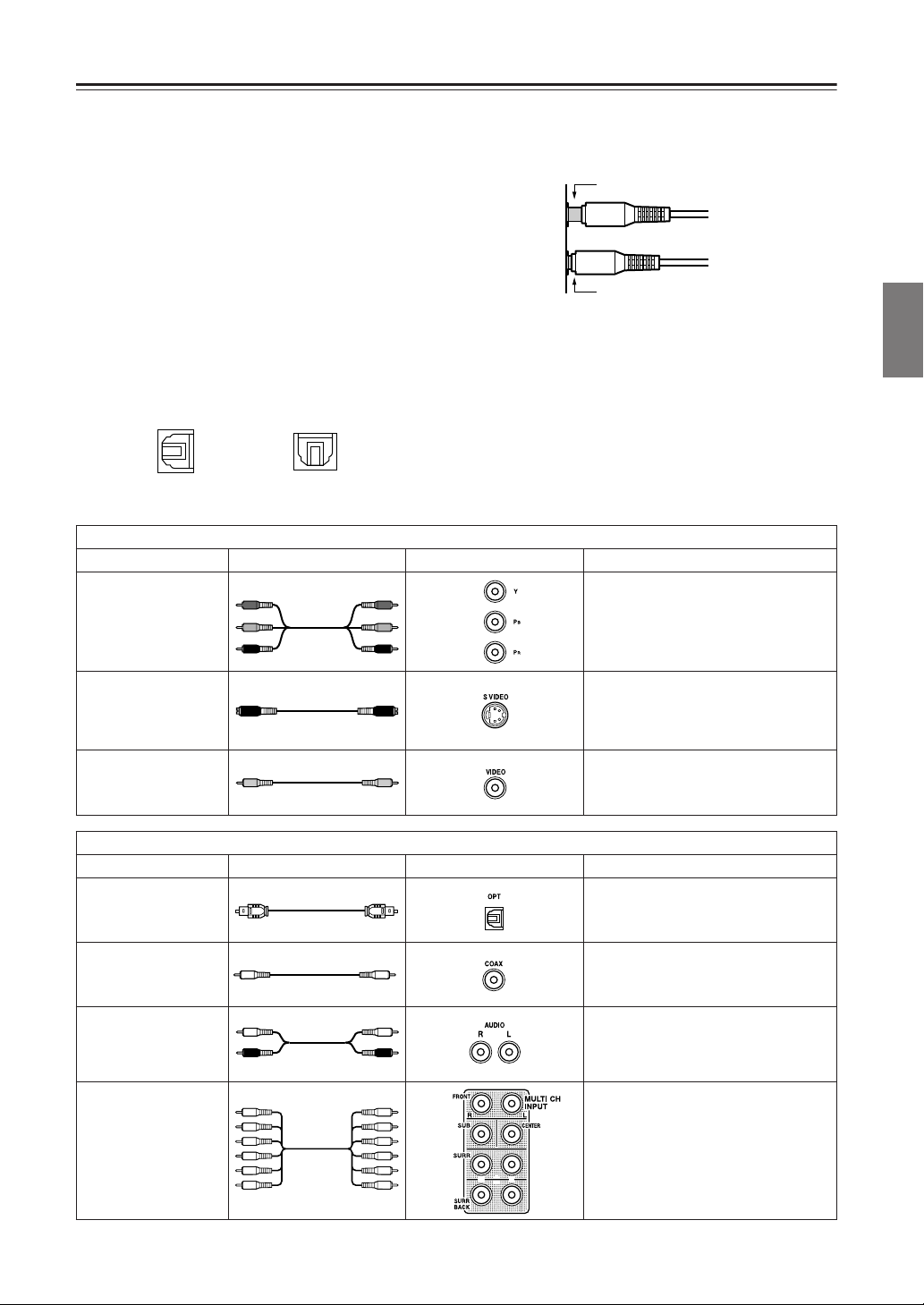
AV Cables and Connectors
• Always refer to the instructions that came with the
component that you are connecting.
• Do not plug in the power cord until all connections
have been properly made.
• For input jacks, red connectors (marked R) are
• Insert all plugs and connectors securely. Improper
connections can result in noise, poor performance,
or damage to the equipment.
Improper connection
used for the right channel, white connectors
(marked L) are used for the left channel, and
yellow connectors (marked V) are used for video
connection.
• The optical digital jacks are all of shutter-type
construction. Connect an optical cable by first
making sure the cable is oriented correctly and
then inserting it into the jack by pushing the
shutter lid inwards.
Front optical jackRear optical jack
• Do not bind audio/video connection cables with
power cords and speaker cables. Doing so may
adversely affect the picture and sound quality.
Inserted completely
Cables are depicted in the connection diagrams as shown below.
Types of video connection cables and terminals
Cable names Cable forms Terminal shapes Description
Component video separates the luminance
(Y) and color difference signals (P
providing the best picture quality. Some TV
manufacturers label their component video
inputs differently.
Component video
connection cable
Y
P
B
R
P
Y
P
B
R
P
, PB),
R
Facilities and Connections
The video quality is higher than the one
S video connection
cable
Video connection
cable
using the composite video connection. The
video component control signals such as
aspect ratio signal cannot be sent through
this connection.
This is the standard video connection
method and most of the video components
like TV and VCR are equipped with the
terminals of this type.
Types of audio connection cables and terminals
Cable names Cable forms Terminal shapes Description
You can enjoy various type of digital sound
Optical cable
Coaxial cable
Audio connection
cable
Multichannel
connection cable
R
L
including Dolby Digital format sound. The
sound quality is equal to the one available
through the coaxial cable connection.
You can enjoy various type of digital sound
including Dolby Digital format sound. The
sound quality is equal to the one available
through the optical cable connection.
This connection carries analog audio
signals.
These types of terminals will be found on
DVD players that support DVD-Audio
format.
19
Page 20
Connecting to Audio/Video Equipment
T
Here is an explanation of typical ways to connect various
components to the DTR-7.4. There are many ways that
any one component can be connected, and it is up to you
to decide which method best fits your situation. The
directions given here are only one option and should
only be thought of as such. It is best to fully understand
the nature of each connector and terminal as well as
those of your components and their features to ascertain
which method of connection is best.
COMPONENT VIDEO INPUT/OUTPUT
For DVD players or other devices that have component
video connectors, the DTR-7.4 has two banks of
component video input connectors (Y, P
B, PR) for direct
component video input. The DTR-7.4 also has one bank
of component video output connectors for direct
component video output to the matrix decoder of a
television, projector, or other display device. By sending
the pure component video signal directly, the signal
forgoes the extra processing that normally would
degrade the image. The result is vastly increased image
quality, with incredibly lifelike colors and crisp details.
VIDEO IN/OUT
These are the video inputs and outputs. On the rear
panel, there are five video inputs and two video outputs
and each one includes both composite video and S video
configurations.
Connect VCRs, VTRs, LD players, DVD players, and
other video components to the video inputs. Connect
VCRs, VTRs, and other recording components to the
video outputs to make video recordings.
• When connecting a VCR or other video component,
make sure you connect its audio and video leads to the
same bank (e.g., both to VIDEO 3).
• The Video 5 inputs are located on the front panel.
The flow of the video signals is as follows:
Signals that comes in from COMPONENT VIDEO INPUT
are only output to COMPONENT VIDEO OUTPUT.
When connecting a video player to the COMPONENT
VIDEO INPUT jacks, be sure to connect your television
to the COMPONENT VIDEO OUTPUT jacks.
Signals that come in from VIDEO and S VIDEO IN are
output to VIDEO, S VIDEO and COMPONENT
VIDEO. When you connect a projector or monitor TV
recorders, CD recorders, DAT decks, or other similar
components.
• Since an analog connection must be made when using
Rec Out or Zone 2, make sure that the connection to the
input source is not digital only, but analog as well.
• When using an optical input or output jack, always use
an optical fiber cable.
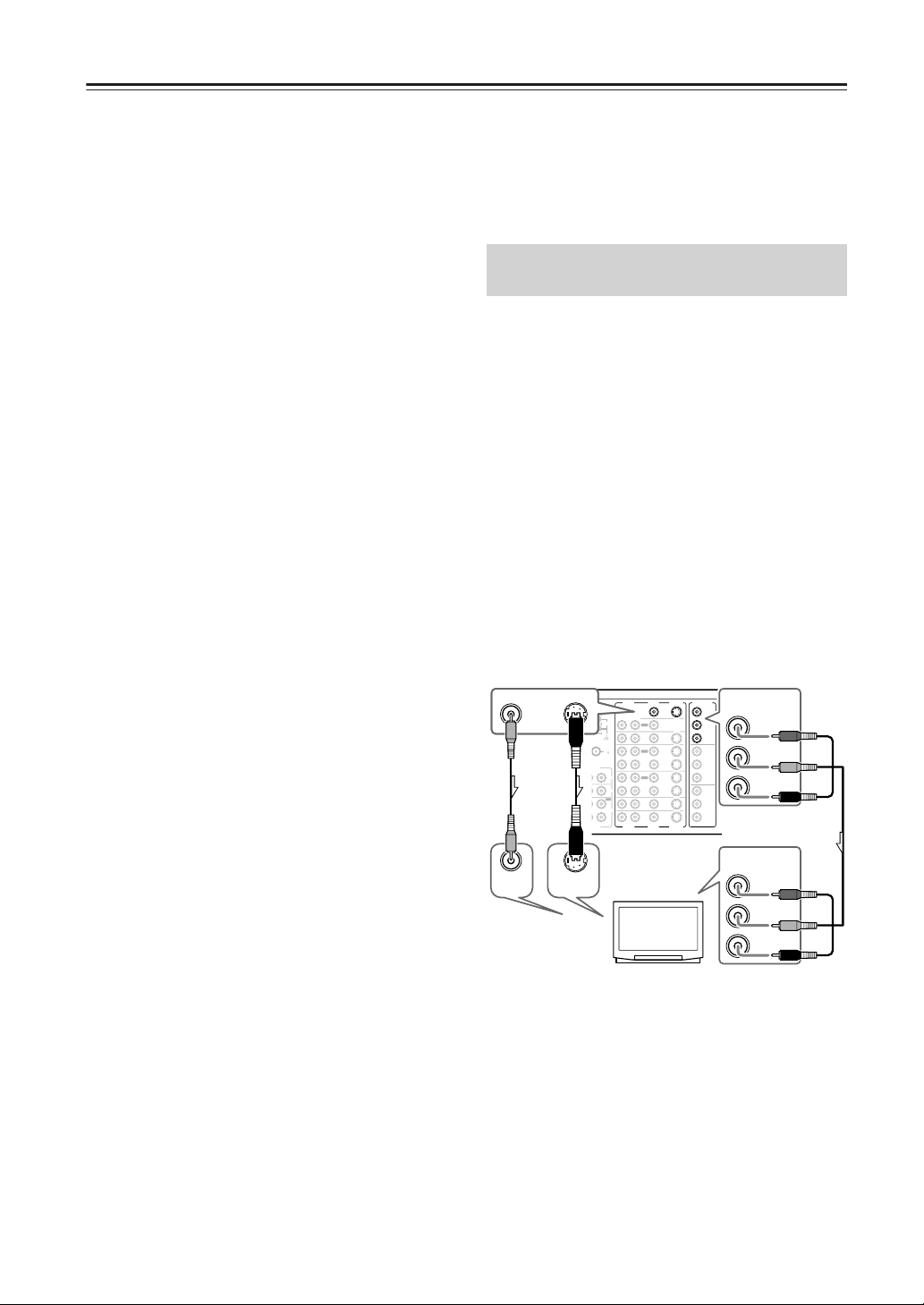
Connecting a Television Monitor or
Projector (MONITOR OUT)
The DTR-7.4 is equipped with a simple Y/C separate
circuit and simple Y/C mixed circuit. Since both the
signals from the S VIDEO and VIDEO inputs are output
to the MONITOR OUT S VIDEO output, if the
television or projector is equipped with an S video input,
it is unnecessary to connect the video connectors. If it is
equipped with only a video input, connect it to the
MONITOR OUT VIDEO output.
Using an RCA video connection cable, connect the
video input jack (composite) of the device to the MONITOR OUT VIDEO jack of the DTR-7.4. Or if the
device has an S video input jack, connect it to the
MONITOR OUT S VIDEO jack of the DTR-7.4 using
an S video connection cable. Or if the device has component video inputs, connect them to the bank of COMPONENT VIDEO OUTPUT jacks on the DTR-7.4.
When you use the connections described above, video
signals that come in from S VIDEO and VIDEO IN are
output to the TV, projector, etc.
VIDEO
VIDEO
IN
MONITOR
OUT
S VIDEO
S VIDEO
IN
ENNA
AM
FM
75
UDIO
L
PHONO
IN
CD
IN
OUT
TAPE
IN
L
UDIO
VIDEO
AUDIO
MONITOR
OUT
L
R
ZONE 2
OUT
DVD
IN
OUT
VIDEO 1
IN
OUT
VIDEO 2
IN
VIDEO 3
IN
VIDEO 4
IN
L
R
VIDEO
AUDIO
TV,
projector,
etc.
S VIDEO
S VIDEO
COMPONENT
VIDEO
OUTPUT
Y
B
P
PR
INPUT 1
Y
B
P
PR
INPUT 2
Y
P
B
PR
COMPONENT
VIDEO
OUTPUT
Y
P
B
PR
COMPONENT
VIDEO
INPUT
Y
P
B
PR
to COMPONENT VIDEO inputs, you do not have to
connect them to VIDEO and S VIDEO inputs by setting
the Video Setup Sub-menu (See page 38).
AUDIO IN/OUT
These are the analog audio inputs and outputs. There are
eight audio inputs and three audio outputs on the rear
panel. The audio inputs and outputs require RCA-type
connectors.
DIGITAL IN/OUT
On the rear panel of the DTR-7.4, there are three coaxial
digital inputs, three optical digital inputs, and two
optical digital outputs. To the digital inputs, connect CD
Note that the OSD Menu data will be output to the
MONITOR OUT VIDEO, S VIDEO and COMPONENT VIDEO jacks. When you connect any OSD-specific monitor TV to the VIDEO connectors, you can
disable the OSD output to COMPONENT VIDEO
OUTPUT. To disable the OSD output, select Setup
Menu → Preference → OSD Setup → Component
Video, and then select “OSD Off” (See page 63).
players, LD players, DVD players, or other digital
source components. To the digital output, connect MD
20
Page 21

Connecting to Audio/Video Equipment—Continued
Connecting a DVD Player (DVD)
DIGITAL
DIGITAL
COAX
1
DIGITAL
COAX
IN
OUT
PRE OUT
IN
R
COAX
FRONT
1
SUB
2
SURR
3
SURR
R
BACK/
OPT
ZONE 2
1
FRONT
2
R
SUB
3
SURR
AUDIO
DIGITAL
OUT
R
OPT
1
SURR
BACK
R
2
GND
R
AUDIO
OUT
ANTENNA
L
CENTER
L
MULTICH
INPUT
AUDIO
L
R
CENTER
L
L
R
IN
AUDIO
L
AUDIO
L
R
AM
FM
75
L
PHONO
IN
VIDEO S VIDEO
CD
IN
OUT
TAPE
IN
L
R
L
DVD
AUDIO
VIDEO
OUT
DVD player
Using an RCA video connection cable, connect the
video output jack (composite) of the DVD or LD player
to the DVD VIDEO IN jack of the DTR-7.4. Or if the
DVD or LD player has an S video output jack, connect it
to the DVD S VIDEO IN jack with an S video
connection cable. Or if the device has component video
outputs, connect them to one of the banks of
COMPONENT VIDEO INPUT jacks on the DTR-7.4.
On the initial settings of the DTR-7.4, the DVD input
source is set for the COMPONENT VIDEO INPUT 1
jacks.
If you connect the DVD or LD player to the
COMPONENT VIDEO INPUT 2 jacks, this must be
changed at Setup Menu → Input Setup → Video Setup
→ Component Video (See page 38).
Using an RCA audio connection cable, connect the
audio output jacks of the DVD or LD player to the DVD
AUDIO IN jacks of the DTR-7.4. Make sure that you
properly connect the left channel to the L jack and the
right channel to the R jack.
If the device has a digital output, connect it to either the
DIGITAL IN COAX jack or DIGITAL IN OPT jack of
the DTR-7.4, depending on the type of connector on the
DVD player.
On the initial settings of the DTR-7.4, the DVD input
source is set for digital input at the COAX 1 jack.
If the digital connection is made at a different jack, this
must be changed at Setup Menu → Input Setup →
Digital Setup (See page 36).
Make sure of your DVD player’s digital output settings.
You need to access the On Screen Menu of your DVD
player. See the owner’s Manual on your DVD player.
Also, you need to aware of the Table of contents for the
movie, selecting the movie for Dolby Digital or DTS,
depends how the movie is encoded.
VIDEO
OUT
IN
OUT
IN
OUT
IN
IN
IN
VIDEO
S VIDEO
OUT
COMPONENT
S VIDEO
VIDEO
OUTPUT
MONITOR
OUT
Y
ZONE 2
P
B
DVD
PR
INPUT 1
Y
VIDEO 1
P
B
PR
VIDEO 2
INPUT 2
Y
VIDEO 3
P
B
VIDEO 4
PR
S VIDEO
B
P
Y
COMPONENT
VIDEO
OUTPUT
COMPONENT
VIDEO
INPUT 1
Y
P
B
PR
PR
Connecting a Video Cassette
Recorder (VIDEO 1)
DIGITAL
PRE OUT
IN
L
R
COAX
FRONT
1
SUB
2
SURR
3
SURR
R
L
BACK/
OPT
ZONE 2
1
FRONT
2
R
SUB
3
SURR
DIGITAL
OUT
R
L
OPT
1
SURR
BACK
2
GND
ANTENNA
CENTER
AM
FM
75
MULTICH
INPUT
AUDIO
L
L
R
CENTER
PHONO
IN
AUDIO
CD
IN
OUT
RL
TAPE
IN
L
R
AUDIO
AUDIO
R
OUT
R
AUDIO
L
L
IN
RL
AUDIO IN
VIDEOINS VIDEO
IN
Using RCA video connection cables, connect the video
output jack (composite) of the video cassette recorder to the
VIDEO 1 VIDEO IN jack of the DTR-7.4 and connect the
video input jack of the video cassette recorder to the
VIDEO 1 VIDEO OUT jack of the DTR-7.4. Or if the
video cassette recorder has S video input and output jacks,
connect them to the VIDEO 1 S VIDEO IN and OUT jacks
of the DTR-7.4 using S video connection cables. Or if the
video cassette recorder has component video outputs,
connect them to one of the banks of COMPONENT
VIDEO INPUT jacks on the DTR-7.4.
On the initial settings of the DTR-7.4, the VIDEO 1
input source is set for the COMPONENT VIDEO
INPUT 2 jacks.
If you connect the video cassette recorder to the
COMPONENT VIDEO INPUT 1 jacks, this must be
changed at Setup Menu → Input Setup → Video Setup
→ Component Video (See page 38).
Using RCA audio connection cables, connect the audio
output jacks of the video cassette recorder to the VIDEO
1 AUDIO IN jacks of the DTR-7.4 and connect the audio
input jacks of the video cassette recorder to the VIDEO
1 AUDIO OUT jacks of the DTR-7.4. Make sure that
you properly connect the left channels to the L jacks and
the right channels to the R jacks.
If you are connecting a digital output device to the
VIDEO 1 jack instead of a VCR, connect it to either the
DIGITAL IN COAX jack or DIGITAL IN OPT jack,
depending on the type of connector on the device.
On the initial settings of the DTR-7.4, the VIDEO 1
input source is set for digital input at the COAX 2 jack.
If the digital connection is made at a different jack, this
must be changed at Setup Menu → Input Setup →
Digital Setup (See page 36).
COMPONENT
VIDEO
S VIDEO
VIDEO
OUTPUT
MONITOR
OUT
Y
ZONE 2
B
DVD
VIDEO 1
VIDEO 2
VIDEO 3
VIDEO 4
S VIDEO
VIDEO 1
RL
AUDIO OUT
P
PR
INPUT 1
Y
B
P
PR
INPUT 2
Y
P
B
PR
OUT
IN
OUT
IN
OUT
VIDEO S VIDEO
IN
IN
IN
VIDEO
VCR
VIDEO
OUT
S VIDEO
OUT
Facilities and Connections
21
Page 22
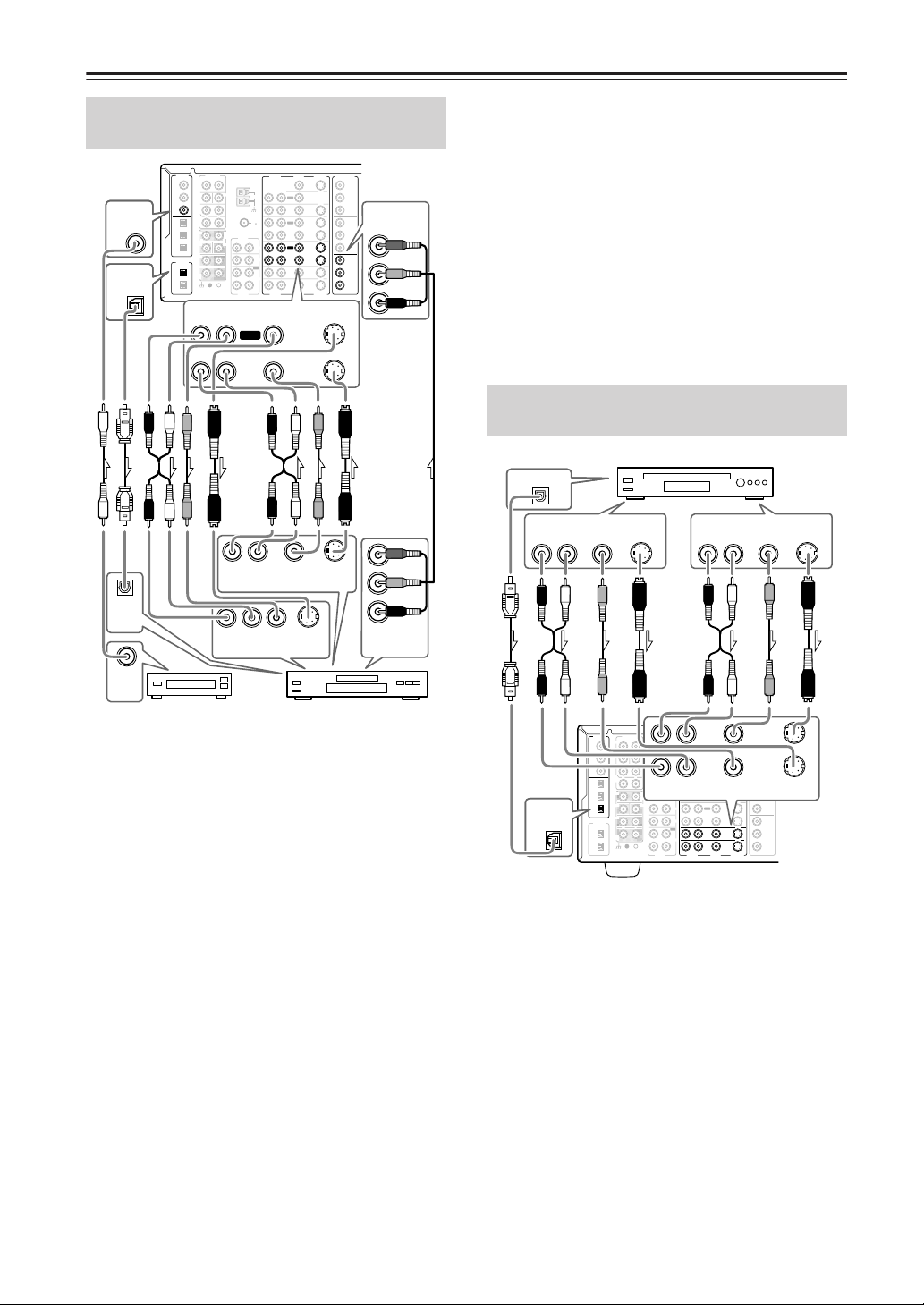
Connecting to Audio/Video Equipment—Continued
Connecting a DVD Recorder or Other
Digital Video Recording Device (VIDEO 2)
DIGITAL
DIGITAL
COAX
3
DIGITAL
OPT
1
IN
OUT
IN
COAX
1
2
3
OPT
1
2
3
DIGITAL
OUT
OPT
1
2
PRE OUT
R
FRONT
SUB
SURR
SURR
R
BACK/
ZONE 2
FRONT
R
SUB
SURR
R
SURR
BACK
GND
AUDIO
RL
ANTENNA
L
CENTER
AM
L
FM
75
MULTICH
INPUT
AUDIO
L
L
R
CENTER
L
L
R
AUDIO
AUDIO
R
PHONO
IN
CD
IN
OUT
TAPE
IN
R
AUDIO
VIDEO S VIDEO
OUT
RL
IN
RL
AUDIO
OUTPUT
DIGITAL
IN
OPT
DIGITAL
OUT
COAX
OUTPUT
RL
AUDIO
INPUT
VIDEO
INPUT
Digital device
Using RCA video connection cables, connect the video
output jack (composite) of the device to the VIDEO 2
VIDEO IN jack of the DTR-7.4 and connect the video
input jack of the device to the VIDEO 2 VIDEO OUT
jack of the DTR-7.4. Or if the device has S video input
and output jacks, connect them to the VIDEO 2 S
VIDEO IN and OUT jacks of the DTR-7.4 using S video
connection cables. Or if the device has component video
outputs, connect them to one of the banks of
COMPONENT VIDEO INPUT jacks on the DTR-7.4.
On the initial settings of the DTR-7.4, the VIDEO 2
input source is set for the COMPONENT VIDEO
INPUT 2 jacks.
If you connect the device to the COMPONENT VIDEO
INPUT 1 jacks, this must be changed at Setup Menu →
Input Setup → Video Setup → Component Video (See
page 38).
Using RCA audio connection cables, connect the audio output jacks of the device to the VIDEO 2 AUDIO IN jacks of
the DTR-7.4 and connect the audio input jacks of the device
to the VIDEO 2 AUDIO OUT jacks of the DTR-7.4. Make
sure that you properly connect the left channels to the L
jacks and the right channels to the R jacks.
If the device has a digital output, connect it to either the
DIGITAL IN COAX jack or DIGITAL IN OPT jack of the
DTR-7.4, depending on the type of connector on the device.
VIDEO
S VIDEO
MONITOR
OUT
L
ZONE 2
OUT
DVD
IN
OUT
VIDEO 1
IN
OUT
VIDEO 2
IN
VIDEO 3
IN
VIDEO 4
IN
L
VIDEO
S VIDEO
VIDEO 2
VIDEO
S VIDEO
OUTPUT
S VIDEO
INPUT
DVD recorder
COMPONENT
VIDEO
OUTPUT
Y
P
B
PR
INPUT 1
Y
P
B
PR
INPUT 2
Y
P
B
PR
COMPONENT
VIDEO
INPUT 2
Y
P
B
PR
Y
P
B
PR
COMPONENT
VIDEO
OUTPUT
On the initial settings of the DTR-7.4, the VIDEO 2
input source is set for digital input at the COAX 3 jack.
If the digital connection is made at a different jack, this
must be changed at Setup Menu → Input Setup →
Digital Setup (See page 36).
If the device has a digital input, connect it to the DIGITAL OUT OPT jack of the DTR-7.4 for digital recording of the REC OUT signal from the DTR-7.4.
However, if the same device also has a digital output
and it has already been connected to the DTR-7.4, you
cannot connect the digital input of the device to the
DIGITAL OUT jack of the DTR-7.4 simultaneously.
Note:
The output from the DIGITAL OUT jack of the DTR-7.4
is only the digital signal input to the DIGITAL IN jack.
Connecting a Satellite Tuner, Television, or Settop Box (VIDEO 3 or 4)
Satellite tuner, television, or settop box
DIGITAL OUT
OPT
VIDEO
VIDEO
AUDIO
OUT
RL
DIGITAL
IN
OPT
3
S VIDEO
OUT
OUT
DIGITAL
PRE OUT
IN
COAX
1
2
3
OPT
1
2
3
DIGITAL
OUT
OPT
1
2
ANTENNA
L
R
FRONT
SUB
CENTER
SURR
SURR
R
L
BACK/
ZONE 2
FRONT
MULTICH
INPUT
R
L
R
SUB
CENTER
SURR
R
L
SURR
BACK
GND
R
AUDIO
R
AM
FM
75
RL
AUDIO
AUDIO
L
PHONO
IN
CD
IN
OUT
TAPE
IN
R
L
AUDIO
AUDIO
AUDIO
OUT
RL
IN
VIDEO
S VIDEO
MONITOR
OUT
L
ZONE 2
OUT
IN
DVD
IN
OUT
VIDEO 1
VIDEO S VIDEO
IN
OUT
VIDEO 2
IN
VIDEO 3
IN
VIDEO 4
IN
L
VIDEO
S VIDEO
Using an RCA video connection cable, connect the
video output jack (composite) of the device to the
VIDEO 3 (or 4) VIDEO IN jack of the DTR-7.4. Or if
the device has an S video output jack, connect it to the
VIDEO 3 (or 4) S VIDEO IN jack of the DTR-7.4 using
an S video connection cable. Or if the device has component video outputs, connect them to one of the banks of
COMPONENT VIDEO INPUT jacks on the DTR-7.4.
On the initial settings of the DTR-7.4, the VIDEO 3
and 4 input sources are set for the COMPONENT
VIDEO INPUT 2 jacks.
If you connect the device to the COMPONENT VIDEO
INPUT 1 jacks, this must be changed at Setup Menu → Input
Setup → Video Setup → Component Video (See page 38).
Using an RCA audio connection cable, connect the
audio output jack of the device to the VIDEO 3 (or 4)
AUDIO IN jacks of the DTR-7.4. Make sure that you
properly connect the left channel to the L jack and the
right channel to the R jack.
OUT
VIDEO 3
COMPONENT
VIDEO
OUTPUT
Y
P
VIDEO 4
PR
INPUT 1
Y
P
PR
INPUT 2
Y
P
PR
S VIDEO
OUT
B
B
B
22
Page 23

Connecting to Audio/Video Equipment—Continued
When hooking up a TV with audio outputs, make sure
the TV’s audio output setting. You might have to go
through the TV’s menu and set the TV Fixed audio
output and then internal speakers off.
If the device has a digital output, connect it to either the
DIGITAL IN COAX jack or DIGITAL IN OPT jack of the
DTR-7.4, depending on the type of connector on the device.
On the initial settings of the DTR-7.4, the VIDEO 3
input source is set for digital input at the OPT 3 jack.
If the digital connection is made at a different jack, this
must be changed at Setup Menu → Input Setup → Digital
Setup (See page 36).
On the initial settings of the DTR-7.4, the VIDEO 4
input source is not set for digital input. If you are
connecting a digital component, these settings must be
changed at Setup Menu → Input Setup → Digital Setup
(See page 36).
Connecting Video Camera, etc.
(Video 5 Input)
Using an RCA video connection cable, connect the
video output jack (composite) of the device to the Video
5 Video jack of the DTR-7.4. Or if the device has an S
video output jack, connect it to the Video 5 S Video jack
of the DTR-7.4 using an S video connection cable.
Using an RCA audio connection cable, connect the
audio output jack of the device to the Video 5 Audio
jacks of the DTR-7.4. Make sure that you properly
connect the left channel to the L jack and the right
channel to the R jack.
If the device has an optical digital output, connect it to
the Video 5 Digital jack of the DTR-7.4.
The Video 5 digital input is fixed to the OPTICAL
input on the front panel.
Front panel
Video 5 Input
DIGITAL
S VIDEO
OUT
OUT
Video camera/ Video
game (Video 5 Input)
AUDIO OUT VIDEO
R
OUT
L
L
R
Digital
S Video
Video L R
Audio
DTR-7.4
L
R
Connecting a Compact Disc Player
(CD)
DIGITAL
DIGITAL
OPT
1
PRE OUT
IN
R
COAX
FRONT
1
SUB
2
SURR
3
SURR
R
BACK/
OPT
ZONE 2
1
FRONT
IN
2
R
SUB
3
SURR
DIGITAL
OUT
R
OPT
1
SURR
BACK
2
GND
OPT
ANTENNA
L
CENTER
L
MULTICH
INPUT
L
R
CENTER
L
R
DIGITAL
OUT
AUDIO
L
R
AM
FM
75
AUDIO
L
PHONO
IN
CD
IN
OUT
TAPE
IN
L
R
L
AUDIO
AUDIO
AUDIO OUT
Using an RCA audio connection cable, connect the
output jacks of the compact disc player to the CD
AUDIO jacks of the DTR-7.4. Make sure that you
properly connect the left channel to the L jack and the
right channel to the R jack.
If the compact disc player has a digital output, connect it
to either the DIGITAL IN COAX jack or DIGITAL IN
OPT jack of the DTR-7.4, depending on the type of
connector on the compact disc player.
On the initial settings of the DTR-7.4, the CD input
source is set for digital input at the OPT 1 jack.
If the digital connection is made to a different jack, this
must be changed at Setup Menu → Input Setup → Digital Setup (See page 36).
.
Connecting a Turntable (PHONO)
DIGITAL
PRE OUT
IN
ANTENNA
L
R
COAX
FRONT
1
SUB
CENTER
2
SURR
3
SURR
R
L
BACK/
OPT
ZONE 2
1
FRONT
MULTICH
2
INPUT
AUDIO
R
L
R
SUB
CENTER
3
SURR
DIGITAL
OUT
R
L
OPT
1
SURR
BACK
2
GND
R
AUDIO
L
L
AM
FM
75
PHONO
IN
CD
IN
OUT
TAPE
IN
AUDIO
AUDIO
L
R
RL
OUT
IN
OUT
IN
OUT
IN
IN
IN
L
R
AUDIO
VIDEO
VIDEO
Ground wire (earth)
Using an RCA audio connection cable, connect the
output jacks of the turntable to the PHONO audio jacks
of the DTR-7.4. Make sure that you properly connect the
left channel to the L jack and the right channel to the R
jack.
Note:
The DTR-7.4 is designed for use with moving magnet
cartridges. For proper operation, connect a ground (or
earth) wire to the GND terminal. For some turntables,
however, connecting the ground wire may cause
increased noise, and in such a case, a ground wire is not
necessary and should not be connected.
VIDEO
S VIDEO
MONITOR
OUT
ZONE 2
OUT
DVD
IN
AUDIO
OUT
RL
VIDEO 1
IN
OUT
VIDEO 2
IN
VIDEO 3
IN
VIDEO 4
IN
VIDEO
S VIDEO
RL
COMPONENT
S VIDEO
MONITOR
OUT
ZONE 2
PHONO
DVD
IN
VIDEO 1
VIDEO 2
VIDEO 3
VIDEO 4
S VIDEO
COMPONENT
VIDEO
OUTPUT
Y
P
B
PR
INPUT 1
Y
P
B
CD
IN
PR
INPUT 2
Y
B
P
PR
CD player
VIDEO
OUTPUT
Y
P
B
PR
INPUT 1
Y
B
P
PR
INPUT 2
Y
B
P
PR
Facilities and Connections
23
Page 24
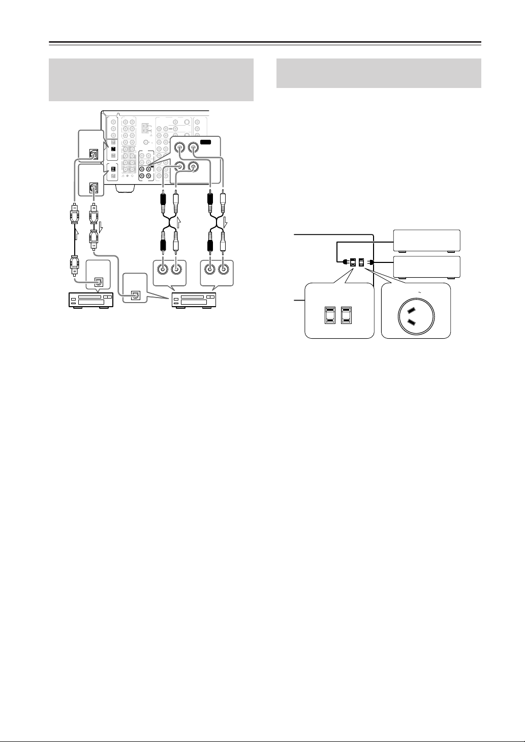
Connecting to Audio/Video Equipment—Continued
Connecting a Cassette Tape Deck,
MD Recorder, DAT Deck, or CD
Recorder (TAPE)
DIGITAL
IN
COAX
FRONT
1
SUB
2
SURR
3
DIGITAL
OPT
2
DIGITAL
OPT
OUT
SURR
BACK/
OPT
ZONE 2
1
IN
FRONT
2
R
SUB
3
SURR
DIGITAL
OUT
OPT
1
SURR
BACK
2
GND
1
DIGITAL
OUT
OPT
MD recorder, DAT deck,
or CD recorder
PRE OUT
R
R
R
DIGITAL
OPT
AUDIO
ANTENNA
L
R
CENTER
AM
L
FM
75
MULTICH
INPUT
AUDIO
L
L
R
CENTER
PHONO
IN
CD
IN
L
OUT
TAPE
IN
R
L
R
AUDIO
AUDIO
RL
AUDIO OUT
IN
Cassette tape deck, MD recorder,
DAT deck, or CD recorder
Using RCA audio connection cables, connect the output
jacks (PLAY) of the device to the TAPE AUDIO IN jacks
of the DTR-7.4 and connect the input jacks (REC) of the
device to the TAPE AUDIO OUT jacks of the DTR-7.4.
Make sure that you properly connect the left channels to
the L jacks and the right channels to the R jacks.
If the device has a digital output, connect it to either the
DIGITAL IN COAX jack or DIGITAL IN OPT jack of the
DTR-7.4, depending on the type of connector on the device.
On the initial settings of the DTR-7.4, the TAPE input
source is set for digital input at the OPT 2 jack.
If the digital connection is made to a different jack, this
must be changed at Setup Menu → Input Setup →
Digital Setup (See page 36).
If the device has a digital input, connect it to the
DIGITAL OUT OPT jack of the DTR-7.4 for digital
recording of the REC OUT signal from the DTR-7.4.
However, if the same device also has a digital output and
it has already been connected to the DTR-7.4, you
cannot connect the digital input of the device to the
DIGITAL OUT jack of the DTR-7.4 simultaneously.
Note:
The output from the DIGITAL OUT jack of the DTR-7.4
is only the digital signal input to the DIGITAL IN jack.
L
OUT
IN
OUT
IN
OUT
IN
IN
IN
L
VIDEO
S VIDEO
MONITOR
OUT
ZONE 2
DVD
VIDEO 1
VIDEO 2
VIDEO 3
VIDEO 4
RL
VIDEO
S VIDEO
AUDIO
COMPONENT
VIDEO
OUTPUT
INPUT 1
INPUT 2
Y
B
P
PR
Y
OUT
B
P
TAPE
PR
Y
B
P
IN
PR
RL
AUDIO IN
Connecting the Power Cords from
Other Devices
The DTR-7.4 is equipped with AC mains outlets for
connecting the power cords from other devices so that
their power is supplied through the DTR-7.4. By doing
this, you can leave the connected device turned on and
have the Standby/On button on the DTR-7.4 turn on and
off the device together with the DTR-7.4.
The shape, number, and total capacity of the AC
outlets may differ depending on the area of purchase.
Caution:
Make sure that the total capacity of the components
connected to the DTR-7.4 does not exceed the capacity
that is printed on the rear panel (e.g., TOTAL 120W).
AC OUTLETS
AC 120 V 60 Hz
SWITCHED
TOTAL 120W 1A MAX.
USA and Canadian models
AC OUTLET
AC 230-240 V 50
Hz
SWITCHED 100W MAX.
Australian model
24
Page 25
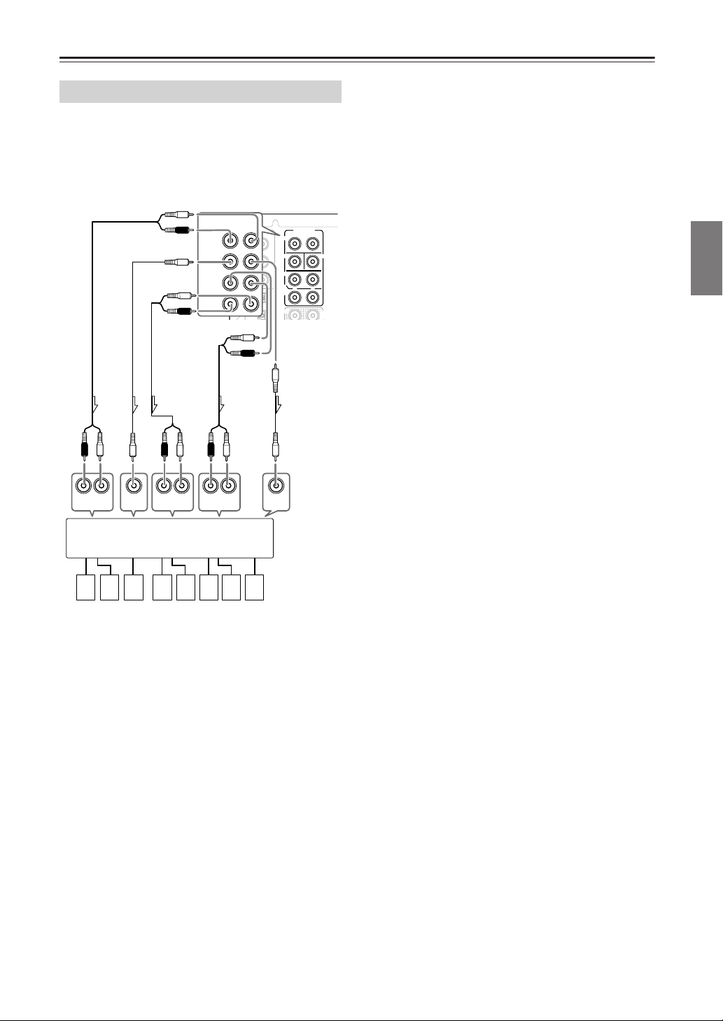
Connecting to Audio/Video Equipment—Continued
C
A
Connecting Auxiliary Power Amplifier
These jacks are for connecting an auxiliary power
amplifier.
You can use an auxiliary power amplifier to listen at
louder volumes than you can with the DTR-7.4 alone.
When using a power amplifier, connect each speaker to
the power amplifier.
L
Subwoofer
L
to White
to Red
to Purple
to Brown
to Tan
Surround
back
R
PRE OUT
RL
to Blue
to Gray
DIGITAL
COAX
1
2
3
OPT
1
2
L
R
FRONT
R
SUB
SURR
L
SURR
BACK/
ZONE 2
R
Surround
IN
FRONT
SUB
SURR
SURR
BACK/
ZONE 2
FRONT
to Green
PRE OUT
R
R
L
CENTER
L
MULTI
INPUT
Center
L
L
R
Front
R
INPUT
RL
INPUT
RL
Power amplifier
1. Front left speaker
2. Front right speaker
3. Subwoofer
4. Surround back left
speaker
5. Surround back right
speaker
INPUTINPUT INPUT
RL
87654321
6. Surround left
speaker
7. Surround right
speaker
8. Center speaker
Facilities and Connections
25
Page 26
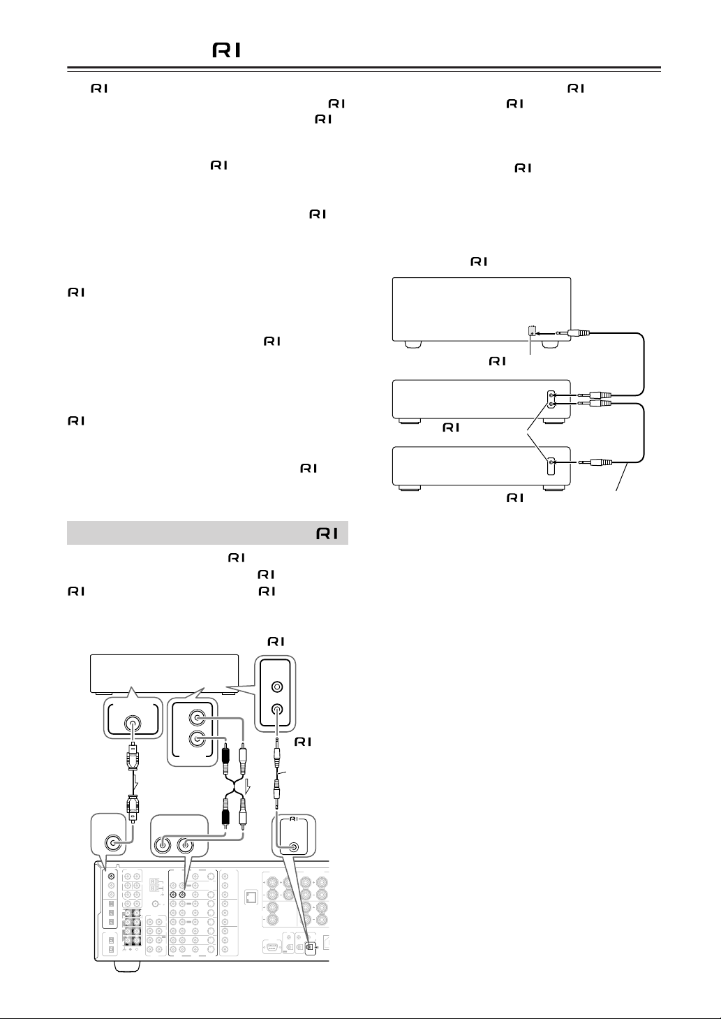
A
Connecting -compatible AV Components
The
terminal on the DTR-7.4 is for connecting other
Integra/Onkyo components equipped with the same
terminal. When a component is connected to the
terminal, it can be operated by the remote controller
supplied with the DTR-7.4. In addition, when you
connect a component to the
terminal, you can also
perform the system operations given below.
Power on/ready function
When the DTR-7.4 is in the standby state, if an
connected component is turned on, the DTR-7.4 also
turns on and the input source selected at the DTR-7.4
automatically switches to that component.
Be aware that this function will not work if the power cord for the
-connected component is connected to the AC OUTLET on
the DTR-7.4, or if the DTR-7.4 has already been turned on.
Direct change function
When the play button is pressed on an
-connected
component, the input source selected at the DTR-7.4
automatically changes to that component.
Power off function
When the DTR-7.4 is placed in the standby state, all
-connected components are also automatically put
into the standby state.
Also, if you press the On button on the DTR-7.4 remote
controller while the DTR-7.4 is turned on, all
connected components (DVD players, CD players, MD
recorders, tuners, etc.) are also turned on.
• When performing operations with
components using the
system, do not use the
remote zone (Zone 2).
• For remote control operation, the audio connection
cables must also be connected.
• If a component has two
terminals, you can use
either one to connect to the DTR-7.4. The other one
can be used to daisy chain with another component.
• With Integra/Onkyo DVD players, you can enter the
pre-program code so that you can operate the DVD
player directly with the remote controller without
connecting the
terminals (See page 89).
DTR-7.4
REMOTE
CONTROL
connector
Ex: Integra/Onkyo CD
player
connector
Ex: Onkyo cassette tape
deck
Remote control cable
-connected
Connections for Remote Control ( )
To connect components using the
connect a remote control cable from this
terminal of the other component. An
cable with a 1/8 inch (3.5 mm) miniature two-conductor plug
comes with every cassette tape deck, compact disc player,
MD recorder, and DVD player that has an
Integra/Onkyo DVD player
DIGITAL OUT
DIGITAL
COAX
1
COAX
COAX
IN
DIGITAL
PRE OUT
IN
L
R
FRONT
1
SUB
2
SURR
3
SURR
R
L
BACK/
OPT
ZONE 2
1
FRONT
2
R
SUB
3
SURR
DIGITAL
OUT
R
L
OPT
1
SURR
BACK
2
GND
L
R
ANALOG
OUTPUT
AUDIO
R
AUDIO
ANTENNA
R
CENTER
AM
FM
75
MULTICH
INPUT
AUDIO
L
L
R
CENTER
PHONO
IN
CD
IN
OUT
TAPE
IN
R
L
R
AUDIO
AUDIO
terminal, simply
REMOTE
CONTROL
L
IN
COMPONENT
VIDEO
S VIDEO
VIDEO
MONITOR
OUT
L
ZONE 2
OUT
DVD
IN
OUT
VIDEO 1
IN
OUT
VIDEO 2
IN
VIDEO 3
IN
VIDEO 4
IN
L
VIDEO
S VIDEO
FRONT SPEAKERS
OUTPUT
RL
Y
B
P
PR
INPUT 1
Y
ETHERNET
(Net-Tune)
CENTER
B
P
SPEAKER
PR
INPUT 2
Y
RS232
B
P
PR
26
terminal to the
remote control
terminal.
Remote
control
cable
REMOTE
CONTROL
SURR SPEAKERS
R
L
L
R
I R
A
ZONE 2
12 V
IN
TRIGGER OUT
OUT
REMOTE
B
CONTROL
Page 27
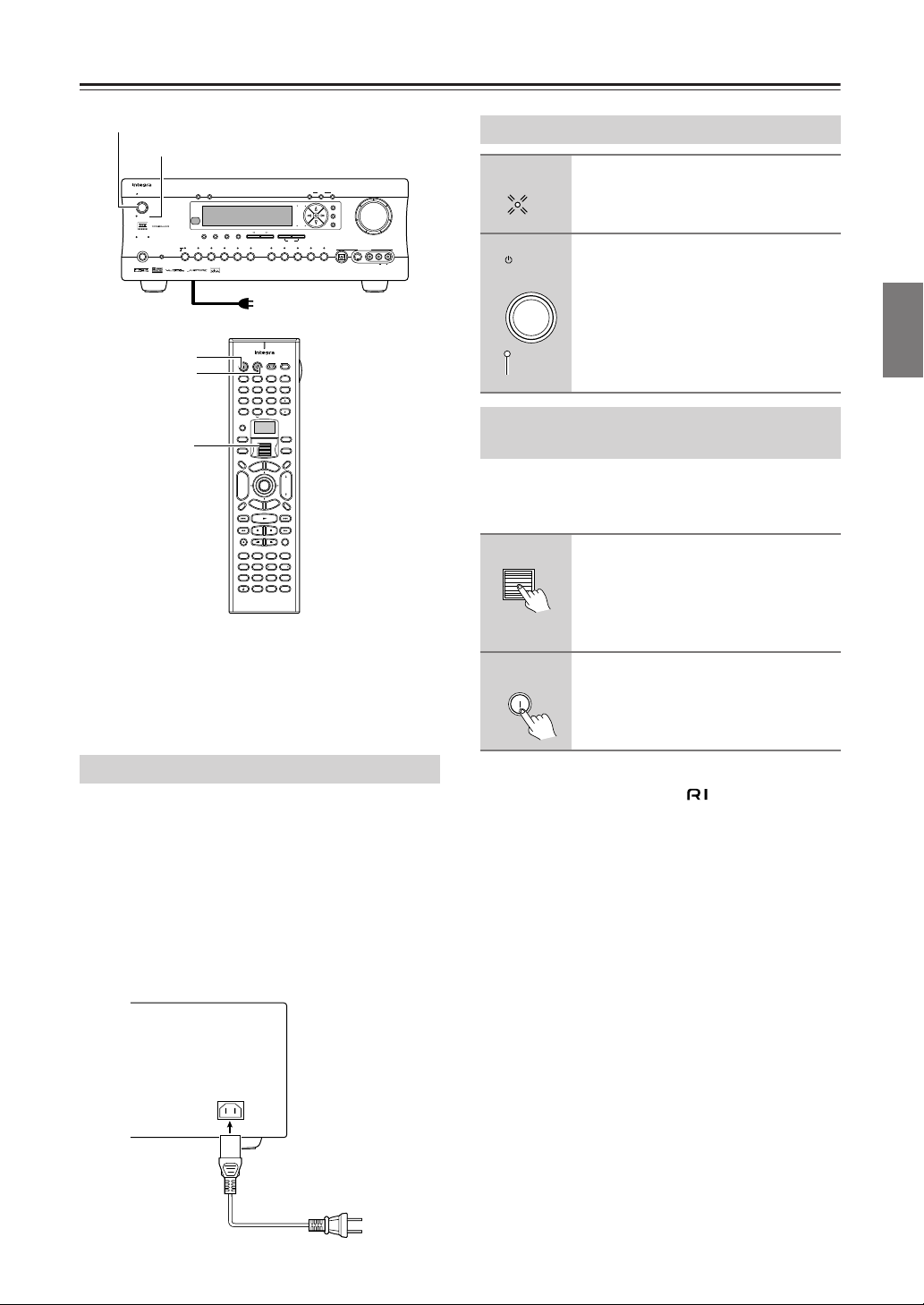
Standby/On
Standby
Turn off
On
Connecting the Power
Standby/On
Standby indicator
Standby/On
Standby
UpsamplingPure Audio
Phones
DimmerDisplay
Surround THX
StereoDirect / Pure Audio
()
Zone 2
GRN
()
Rec
RED
Video 3
Video 2
DVD
Video 1
Audio
Selector
Video 4 Video 5
VCR 2
VCR 1
Rec Out
Zone 2 Of
f
Master Volume
Setup
Tuning
Enter
Return
Preset
Memory FM Mode
DSP
Tape
Clear
Tuner Phono Net AudioCD
A-FO RM Listening Mode Memory
Video 5 Input
Digital
S Video
Video L R
Audio
DTR-7.4
To wall outlet
On
Standby
Scroll Wheel
On Standby
123
@. - ' / ABC DEF
456
GHI JKL MNO
789
PQRS TUV WXYZ
+
10 0
--/---
Custom
Macro
Dimmer
T V
p
o
Input
T
+
CH
Disc
-
R
e
Display
Rec
Surround
THX
Pure A
Direct
Test Tone
CH SEL
Album Ar tist GenrePlaylist
Audio SEL
Caps Delete
T V
Input
+
TV CH
-
TV VOL
Clear
Direct Tuning
Zone 2
InputMode
Sleep
u
M
n
e
e
n
M
u
A
u
d
i
o
A
D
J
VOL
Enter
e
E
d
i
x
i
u
t
G
p
t
u
u
t
e
r
n
S
Muting
Step / Slow
Random
Last Memory
AngleSubtitleAudio
Stereo
All CH ST
MemorySearchA-BRepeat
DSP DSP
Level
+Level
Re-EQ
L Night
Language Loca t ion
-
RC
550M
• Before you plug in the DTR-7.4, confirm that all connections have been made properly.
• Turning on the power may cause a momentary power
surge, which might interfere with other electrical
equipment on the same circuit, such as computers. If
this happens, use a wall outlet on a different circuit.
Turning on the Power
1
2
Plug the power cord into an AC
wall outlet.
Standby
The Standby indicator will light up.
Press the Standby/On button to
turn on the DTR-7.4.
The display will light up and the Standby
indicator will turn off.
If you press the Standby/On button
again, the DTR-7.4 returns to the standby
state.
Turning on the Power from the
Remote Controller
Before you can use the remote controller, you must
perform steps 1 above and place the DTR-7.4 in the
standby state.
1
2
Press the scroll wheel.
“AMP” appears on the remote controller’s display. This is the mode for controlling the DTR-7.4.
Press the On button to turn on the
DTR-7.4.
To set the DTR-7.4 to Standby, press the
Standby button.
Facilities and Connections
Connecting the Supplied Power Cord
Plug the supplied power cord into this AC INLET.
• Do not use a power cord other than the one supplied
with the DTR-7.4. The power cord supplied is
designed for use with the DTR-7.4 and should not be
used with any other device.
• Never have the power cord disconnected from the
DTR-7.4 while the other end is plugged into the wall
outlet. Doing so may cause an electric shock. Always
connect by plugging into the wall outlet last and disconnect by unplugging from the wall outlet first.
AC INLET
DO NOT con-
Power cord
(supplied)
nect the
power cord at
this time.
Note:
Any components connected via will also be turned
on when the remote controller’s On button is pressed.
Memory backup
The DTR-7.4 uses a battery-less memory backup system in order to retain radio presets and other settings
when it is unplugged or in the case of a power failure.
Although no batteries are required, the DTR-7.4 must
be plugged into an AC outlet in order to charge the
backup system.
Once it has been charged, the DTR-7.4 will retain the
settings for several weeks, although this depends on the
environment and time will be shorter in humid climates.
27
Page 28
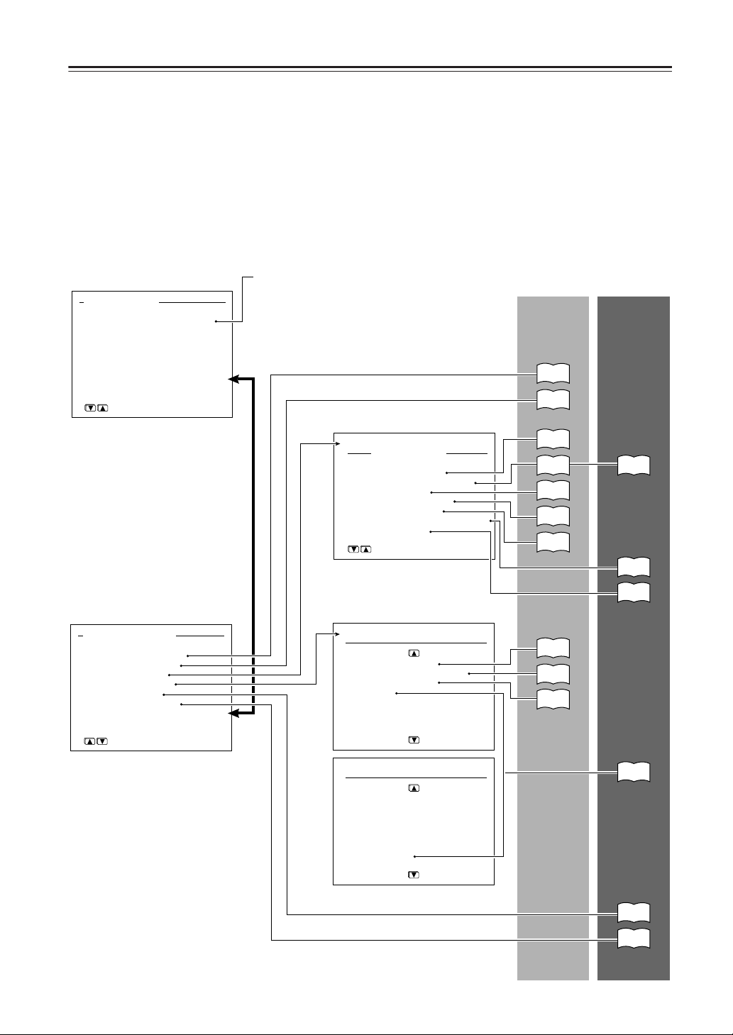
Setup Menu
When making the various settings required to configure your DTR-7.4 for optimum performance, you can either use the
OSD Menu that appears on your television monitor or you can use the display on the front of the DTR-7.4. The OSD
Menu is a settings menu that is displayed on your TV monitor. For your reference when performing the setting procedures, this manual shows both the OSD Menu displayed on your television monitor and the display on the front of the
DTR-7.4.
The Setup Menu consists of the Basic Menu that is divided up into 4 menus, the Hardware Setup Menu, the Speaker
Setup Menu, the Input Setup Menu, and the Audio Adjust Menu, and the Advanced Menu that contains the menus of
the Basic Menu, the Preference Menu, and the Network Setup Menu. These menus are then divided up into various submenus, and these contain settings for you to optimize your home theater as you wish.
The display shown below is an example. The actual contents of your display may differ depending on the model of your
region and the selected input source.
Advanced
Menu
64
56
71
Basic Menu
0.Hardware Setup
1.Speaker Setup
2.Input Setup
3.Audio Adjust
→
Advanced Menu
[ENTER]Quit:[SETUP]
Basic Menu
Your DTR-7.4 is provided with a
Basic Menu for those who are not
familiar with many of the advanced
settings of an AV receiver or for
those who wish to watch movies and
listen to music with a minimal
amount of setup. With the Basic
Menu, the settings that rarely need to
be set or that are only needed for
advanced fine-tuning of the sound
quality are not displayed.
Note:
The Hardware Setup Menu is accessible from the Basic
Menu at an initial setting. After being brought up on the
screen and setting any of its items, the menu is no longer
available from the Basic Menu.
In this case, you can gain access to the menu via the
“→Advanced Menu.”
2.Input Setup
Input:DVD
1.Digital Setup
2.Multichannel Setup
3.Video Setup
4.Character Input
5.IntelliVolume
6.Listening Mode Preset
7.12V Trigger
[ENTER]Quit:[SETUP]
Basic
Menu
30
32
36
38
38
52
53
Advanced Menu
0.Hardware Setup
1.Speaker Setup
2.Input Setup
3.Audio Adjust
4.Preference
5.Network Setup
[ENTER]Quit:[SETUP]
Advanced Menu
The Advanced Menu provides features such as the Listening Mode
Presets that allow you to customize
the output sound for movies and
music just the way you like and the
AV Sync Setup that allows you to
adjust for discrepancies between the
video and audio timing.
→Basic Menu
28
3.Audio Adjust
1.Tone Control
2.Surround Speakers
3.Sound Effect
4.Delay
5.LFE Level
6.Mono
7.Theater-Dimensional
8.Surround
3.Audio Adjust
9.THX
10.Mono Movie
11.Enhance
12.Orchestra
13.Unplugged
14.Studio-Mix
15.TV Logic
→
default
54
54
55
57
62
76
Page 29
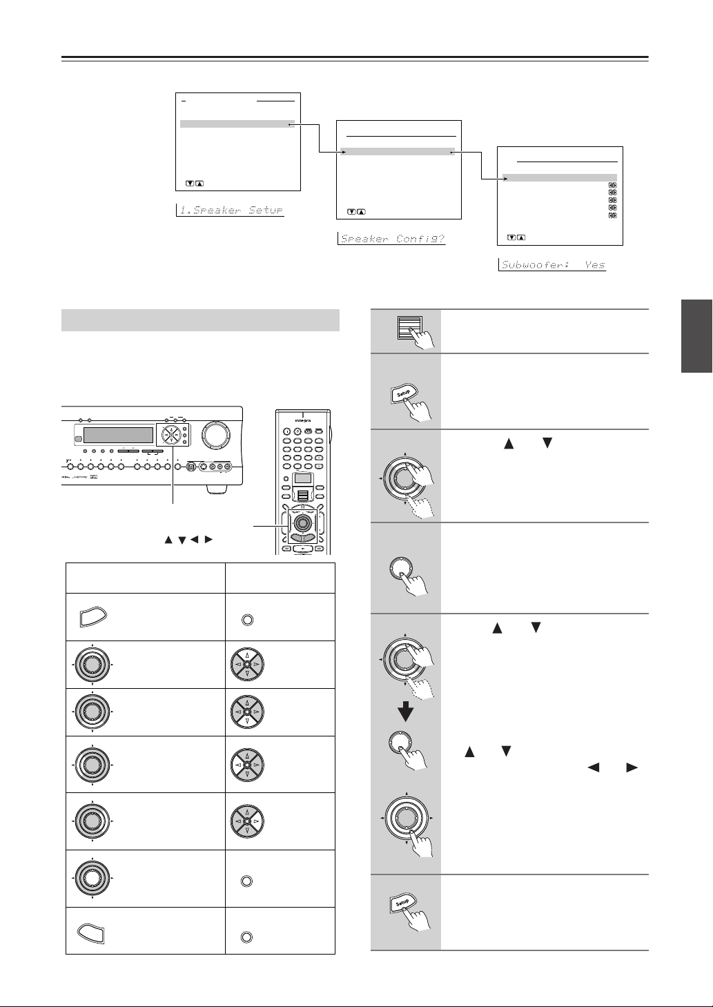
Setup Menu —Continued
e
OSD
Advanced Menu
0.Hardware Setup
1.Speaker Setup
2.Input Setup
3.Audio Adjust
4.Preference
5.Network Setup
→Basic Menu
[ENTER]Quit:[SETUP]
Front panel
dispaly
Main menu
µ
Navigating Through the Setup Menu
You can change settings in the Setup Menu using the
buttons on the front panel and on the remote controller.
The buttons on the remote controller correspond to
those on the DTR-7.4 as shown below.
DimmerDisplay
Surround THX
StereoDirect / Pure Audio
()
2
GRN
()
c
RED
Video 3
Video 2
DVD
Video 1
Video 4 Video 5
VCR 2
VCR 1
Button on remote controller
Memory FM Mode
DSP
Clear
Tape
Tuner Phono Net AudioCD
Rec Out
Zone 2 Of
f
Master Volume
Setup
Tuning
Enter
Return
Preset
A-FO RM Listening Mode Memory
Video 5 Input
Digital
S Video
Video L R
Setup/Enter/
Return/Cursor
/ //
On Standby
123
@. - ' / ABC DEF
456
GHI JKL MNO
789
PQRS TUV WXYZ
+
10 0
Audio
DTR-7.4
--/---
Custom
Macro
Dimmer
T V
Input
+
CH
Disc
-
Display
Button on DTR-7.4
T V
Input
+
TV CH
-
TV VOL
Clear
Direct Tuning
Zone 2
InputMode
Sleep
u
M
n
e
e
n
M
u
p
o
T
A
u
d
i
o
A
D
J
VOL
Enter
e
E
d
i
x
i
u
t
G
R
p
e
t
u
u
t
e
r
n
S
Muting
1.Speaker Setup
1.Speaker Config
2.Speaker Distance
3.Level Calibration
[ENTER]Quit:[SETUP]
Menu
1
2
3
Enter
4
Enter
1-1.Speaker Config
a.Subwoofer :Yes
b.Front L/R :Small
c.Center :Small
d.Surr L/R :Small
e.Surr Back :Small
f.Crossover:80Hz(THX)
Quit:[SETUP]
Sub-menu
Press the scroll wheel when using
the remote controller.
Press the Setup button.
The main menu (Advanced Menu or
Basic Menu) appears on your television
monitor.
Using the and cursor buttons,
select the menu that you want to
enter.
Press the Enter button to enter the
selected menu.
The screen for that menu appears.
Setting Up Your DTR-7.4
p
u
t
e
S
Enter
Setup
(upper edge of
Enter button)
Setup
Setup
Up
5
Enter
Use the and cursor buttons to
select the sub-menu that you want
to enter and press the Enter button.
Each sub-menu has different settings
(lower edge of
Enter
Enter
Enter
Enter
Enter button)
(left edge of
Enter button)
(right edge of
Enter button)
Enter
Down
Enter
Left
Right
Enter
Enter
Enter
6
R
e
t
u
Return
r
n
Return
Return
that can be changed as desired, and they
are all explained in the pages that follow.
To change a setting, first select it using
the
and cursor buttons, and then
change the setting using the
and
cursor buttons.
Press the Setup button to exit the
Setup Menu.
Press the Return button to set the new
settings and return to the previous menu.
29
Page 30
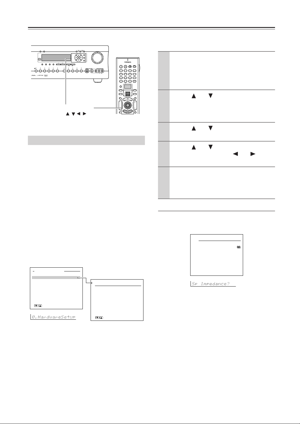
Z
Selecting the Appropriate Setting for Your Connections
If you want to perform these operations using the remote
DimmerDisplay
Surround THX
StereoDirect / Pure Audio
()
one 2
GRN
()
Rec
RED
Video 3
Video 2
DVD
Video 1
Video 4 Video 5
VCR 2
VCR 1
Setup/Enter/Return/
Cursor
DSP
Tape
Memory FM Mode
Tuner Phono Net AudioCD
Rec Out
Zone 2 Of
Tuning
Preset
A-FO RM Listening Mode Memory
Clear
/ //
f
Master Volume
Setup
Enter
Return
Video 5 Input
Digital
S Video
Video L R
Audio
DTR-7.4
On Standby
123
@. - ' / ABC DEF
456
GHI JKL MNO
789
PQRS TUV WXYZ
+
10 0
--/---
Custom
Macro
Dimmer
T V
Input
T
+
CH
Disc
-
R
T V
Input
+
TV CH
-
TV VOL
Clear
Direct Tuning
Zone 2
InputMode
Sleep
u
M
n
e
e
n
M
u
p
o
A
u
d
i
o
A
D
J
VOL
Enter
e
E
d
i
x
i
u
t
G
p
e
t
u
u
t
e
r
n
S
Hardware Setup
In this section, you will perform the initial settings for
the following scenarios.
• When the impedances for speakers connected to the
DTR-7.4 are between 4 and 6 Ω (See page 18).
• When connecting speakers to the ZONE 2
SPEAKERS terminals (See page 66).
• When operating the remote controller using the IR IN
terminal (See page 69).
• When you want to fix the TV Format setting to PAL or
NTSC (Australian model only).
Note:
The settings within the Hardware Setup Menu will need
to be made before you use your DTR-7.4 for the first
time. Once you have selected one of the Hardware Setup
menu items, the setting will not be displayed again when
you enter the Basic Menu. To change the setting at a later
date, select the Advanced Menu to display the Hardware
Setup Menu.
Advanced Menu
0.Hardware Setup
1.Speaker Setup
2.Input Setup
3.Audio Adjust
4.Preference
5.Network Setup
→Basic Menu
[ENTER]Quit:[SETUP]
0.Hardware Setup
1.Speaker Impedance
2.Surr Back/Zone2
3.Remote Setup
4.TV Format
[ENTER]Quit:[SETUP]
controller, first press the scroll wheel.
Display the main menu.
1
Press the Setup button on the front panel, or press
the scroll wheel and then press the Setup button
on the remote controller to display the main menu
on the monitor and front display.
Use the and cursor buttons to select
2
“0. Hardware Setup” and then press the
Enter button.
The “Hardware Setup” menu appears.
Use the and cursor buttons to select
3
an item and then press the Enter button.
Use the and cursor buttons to select
4
an item and then use the and cursor
buttons to set the desired value.
Press the Setup button to exit the Setup
5
menu.
Press the Return button to return to the previous
menu.
Speaker Impedance Sub-menu
Use this sub-menu to set the impedance level of the
DTR-7.4 to match the specifications of the speakers you
are using.
0-1.Speaker Impedance
a.Minimum :6 ohms
Quit:[SETUP]
a. Minimum
6 ohms (default): Select when the impedances of all
speakers are between 6 and 16 Ω .
4 ohms: Select when the impedance of even one
speaker is between 4 and 6 Ω.
Note:
Before you change this setting, be sure to first lower the
volume at the DTR-7.4 to the minimum level.
30
Page 31

Selecting the Appropriate Setting for Your Connections—Continued
Surr Back/Zone 2 Sub-menu
0-2.Surr Back/Zone2
a.Surr Back/Zone2
:Zone2
Quit:[SETUP]
a. Surr Back/Zone 2
Zone 2: Select when connecting the speakers for the
remote zone (Zone 2) to the SURR BACK/ZONE 2
PRE OUT or SURR BACK/ZONE 2 SPEAKERS
terminals (for using the internal amplifier for Zone 2).
Surr Back (default): Select when not connecting
the speakers for the remote zone (Zone 2) to the
SURR BACK/ZONE 2 PRE OUT or SURR BACK/
ZONE 2 SPEAKERS terminals (for using the internal amplifier for the surround back speakers).
Note:
The SURR BACK/ZONE 2 PRE OUT and SURR
BACK/ZONE 2 SPEAKER terminals
In order to have 7.1 channel playback in the main room,
you must set the Surr Back/Zone 2 setting to “Surr
Back.” When set to “Surr Back,” the surround back
signals are output from the SURR BACK/ZONE 2 PRE
OUT and SURR BACK/ZONE 2 SPEAKER terminals.
Connect the surround back speakers to the SURR
BACK/ZONE 2 SPEAKER terminals or to the speakers
terminals of the power amplifier connected to the SURR
BACK/ZONE 2 PRE OUT terminals.
When you are not using the surround back speakers in the
main room and are using the internal amplifier to power the
speakers for the remote zone (Zone 2), set the Surr Back/
Zone 2 setting to are “Zone 2.” When set to “Zone 2,” the
Zone 2 signals are output from the SURR BACK/ZONE 2
PRE OUT and SURR BACK/ZONE 2 SPEAKER
terminals. Connect the remote zone (Zone 2) speakers to
the SURR BACK/ZONE 2 SPEAKER terminals or to the
speaker terminals of the power amplifier connected to the
SURR BACK/ZONE 2 PRE OUT terminals.
At this time, the main room is switched to 5.1 channel
playback mode, and therefore you cannot select the THX
Surround EX, Dolby Digital EX or DTS-ES, which
requires the surround back speakers.
Remote Setup Sub-menu
Use this sub-menu when you have a remote control
sensor connected to the IR IN terminal. The setting in
this sub-menu tells the DTR-7.4 whether the remote
control sensor is being used for operation of the
DTR-7.4 in the main zone or the remote zone (Zone 2).
0-3.Remote Setup
a.Position :Main
b.Remote ID :1
Quit:[SETUP]
a. Position
Main: Select when you are using the remote control
sensor for operation with the remote controller in the
main zone.
Zone 2: Select when you are using the remote
control sensor for operation with the remote
controller in the remote zone (Zone 2).
b. Remote ID
This section explains how to change the DTR-7.4’s
remote control ID. You may need to change this if the
DTR-7.4’s remote controller interferes with other
Integra/Onkyo components located in the same room.
Note:
If you change the DTR-7.4’s remote control ID, be
sure to select the same ID on the remote controller
(See the next section). The default ID for both the
DTR-7.4 and remote controller is 1.
Setting Up Your DTR-7.4
31
Page 32

Selecting the Appropriate Setting for Your Connections—Continued
Changing the Remote Controller’s Control ID
This section explains how to change the remote controller’s ID. You may need to change this if the DTR-7.4’s
remote controller interferes with other Integra/Onkyo
components located in the same room.
Note:
If you change the remote controller’s ID, be sure to select
the same ID on the DTR-7.4. For details on setting up the
DTR-7.4’s remote control ID, refer to the previous
“Remote Setup Sub-menu” section. The default ID for
both the DTR- 7.4 and remote controller is 1.
1
Custom
Hold down the remote controller’s
Custom button for more than three
seconds.
The remote controller enters Custom
mode.
2
Roll the scroll wheel to select
“SETUP” menu, and then press
the scroll wheel.
3
Roll the scroll wheel to select ID
menu, and then press the scroll
wheel.
4
Roll the scroll wheel to select an
ID—1 (default), 2, or 3—and then
press the scroll wheel.
Select the same ID as that set on the
DTR-7.4.
TV Format Sub-menu
a. TV Format (Australian model only)
When you want to reconfigure the settings conforming to the
television format used for the area where you use the DTR-7.4,
use this sub-menu so that no time is wasted on detection.
Auto: This is the default setting. When you leave
this setting unchanged, the television format is
detected and automatically set by the DTR-7.4.
PAL: Use this setting when you know that the televi-
sion format is PAL.
NTSC: Use this setting when you know that the tele-
vision format is NTSC.
0-4.TV Format
a.TV Format
:Auto
Quit:[SETUP]
Speaker Setup
After you have installed the DTR-7.4, connected all the
components, and determined the speaker layout, it is
now time to perform the settings in the Speaker Setup
Menu to optimize the sound acoustics for your
environment and speaker layout.
Before you perform the following settings, it is
important that you first determine the following items:
• The types and sizes of the speakers that are connected.
• The distance from each speaker to the normal
listening position.
Monitor
Front
Front
SW Center
Left
Left
[ ]
[ ]
m/ft
SL SR
[ ]
[ ]
m/ft
Basic Menu
0.Hardware Setup
1.Speaker Setup
2.Input Setup
3.Audio Adjust
→
Advanced Menu
[ENTER]Quit:[SETUP]
[ ]
m/ft
m/ft
SBL SBR
If you want to perform these operations using the remote
controller, first press the scroll wheel.
Display the main menu.
1
Press the Setup button on the front panel, or press
the scroll wheel and then press the Setup button
on the remote controller to display the main menu
on the monitor and front display.
Use the and cursor buttons to select
2
“1. Speaker Setup” and then press the
Enter button.
The “Speaker Setup” menu appears.
Use the and cursor buttons to select
3
an item and then press the Enter button.
Use the and cursor buttons to select
4
an item and then use the and cursor
buttons to set the desired value.
Press the Setup button to exit the Setup
5
menu.
Press the Return button to return to the previous
menu.
Front
Front
Right
Right
m/ft
[ ]
m/ft
[ ]
m/ft
[ ]
m/ft
1.Speaker Setup
1.Speaker Config
2.Speaker Distance
3.Level Calibration
[ENTER]Quit:[SETUP]
32
Page 33

Selecting the Appropriate Setting for Your Connections —Continued
Speaker Config Sub-menu
Use this sub-menu to enter which speakers are
connected and the size of each speaker.
For your reference to speaker size settings, if the diameter
of your speaker unit is larger than 6-1/2” (16 cm), use the
“Large” setting; otherwise use the “Small” setting.
Cone diameter
1-1.Speaker Config
a.Subwoofer :Yes
b.Front :Small
c.Center :Small
d.Surround :Small
e.Surr Back :Small
f.Crossover:80Hz(THX)
Quit:[SETUP]
a. Subwoofer
Yes: Select when a subwoofer is connected.
No: Select when a subwoofer is not connected.
b. Front
Large: Select if the front speakers are large sized.
Small: Select if the front speakers are small sized.
• If “No” is selected for the Subwoofer setting, this
setting is fixed to “Large.”
c. Center
None: Select if no center speaker is connected.
Large: Select if the center speaker is large sized.
Small: Select if the center speaker is small sized.
• If “Small” is selected for the Front setting, “Large”
cannot be selected for this setting.
d. Surround
None: Select if no surround left and right speakers
are connected.
Large: Select if the surround left and right speakers
are large sized.
Small: Select if the surround left and right speakers
are small sized.
• If “Small” is selected for the Front setting, “Large”
cannot be selected for this setting.
e. Surr Back
None: Select if no surround back left and right
speakers are connected.
Large: Select if the surround back left and right
speakers are large sized.
Small: Select if the surround back left and right
speakers are small sized.
• If “None” is selected for the Surround setting, this
setting cannot be selected.
• If “Small” is selected for the Surround setting,
“Large” cannot be selected for this setting.
• If the Surr Back/Zone 2 setting in the Surr Back/
Zone 2 Sub-menu of the Hardware Setup Menu is
set to “Zone 2,” this setting cannot be selected.
f. Crossover
This setting allows you to set the crossover frequency for
your speaker system. The crossover frequency is the
minimum frequency delivered to a speaker and can be
set to 40 Hz, 60 Hz, 80 Hz (THX), 100 Hz, 120 Hz, or
150 Hz.
Select “80Hz (THX)” if you are using a THX-certified
speaker system. This setting is valid when “Subwoofer”
is set to “Yes,” or for speakers that are set to “Small,” at
the “Speaker Config” menu. Frequencies below this are
cut from speakers set to “Small” and sent to the
subwoofer (or to speakers set to “Large”).
Note:
When “Large” is set, the complete frequency range for
that speaker channel will be output. When “Small” is set,
the frequencies below 80 Hz for that speaker channel are
output to the subwoofer. If Subwoofer is set to “No” in
the 1-1. Speaker Config Sub-menu, then they will be
output to the left and right front speakers.
Set all speakers for THX speaker systems to “small.”
Speaker Distance Sub-menu
Use this sub-menu to enter the distance from each
speaker to the normal listening position.
Notes:
• Speakers that you selected “No” or “None” for in the
Speaker Config Sub-menu cannot be selected in this
sub-menu.
• The difference between the distances of different
speakers cannot be set to more than 20 feet (6 meters).
1-2.Speaker Distance
a.Unit :feet
b.Left :12.0ft
c.Center :12.0ft
d.Right :12.0ft
e.Surr Right : 7.0ft
f.Surr Back R : 7.0ft
g.Surr Back L : 7.0ft
h.Surr Left : 7.0ft
i.Subwoofer :12.0ft
Quit:[SETUP]
a. Unit
feet: Select if you will enter the distances in feet.
meters: Select if you will enter the distances in meters.
b. Left
Set the distance from the front left speaker to your
normal listening position. This can be set between 1 and
30 feet in 0.5 feet increments (between 0.3 and 9 meters
in 0.15 meter increments).
c. Center
Set the distance from the center speaker to your normal
listening position. This can be set between 1 and 30 feet
in 0.5 feet increments (between 0.3 and 9 meters in
0.15 meter increments).
Setting Up Your DTR-7.4
33
Page 34

Selecting the Appropriate Setting for Your Connections —Continued
d. Right
Set the distance from the front right speaker to your
normal listening position. This can be set between 1 and
30 feet in 0.5 feet increments (between 0.3 and 9 meters
in 0.15 meter increments).
e. Surr Right
Set the distance from the surround right speaker to your
normal listening position. This can be set between 1 and
30 feet in 0.5 feet increments (between 0.3 and 9 meters
in 0.15 meter increments).
f. Surr Back R
Set the distance from the surround back right speaker to
your normal listening position. This can be set between
1 and 30 feet in 0.5 feet increments (between 0.3 and 9
meters in 0.15 meter increments).
g. Surr Back L
Set the distance from the surround back left speaker to
your normal listening position. This can be set between
1 and 30 feet in 0.5 feet increments (between 0.3 and 9
meters in 0.15 meter increments).
Note:
If the Surr Back/Zone 2 setting in the Surr Back/Zone 2
Sub-menu of the Hardware Setup Menu is set to “Zone
2,” then the Surr Back R and Surr Back L settings will
not be displayed.
h. Surr Left
Set the distance from the surround left speaker to your
normal listening position. This can be set between 1 and
30 feet in 0.5 feet increments (between 0.3 and 9 meters
in 0.15 meter increments).
i. Subwoofer
Set the distance from the subwoofer to your normal
listening position. This can be set between 1 and 30 feet
in 0.5 feet increments (between 0.3 and 9 meters in 0.15
meter increments).
Level Calibration Sub-menu
Use this sub-menu to set the volume for each speaker so
that each volume is heard by the listener at the same
level. This is especially important for speaker layouts
where the left and right speakers are at different distances or in asymmetrical positions due to room designs
and configurations. These settings and the distance settings performed in the Speaker Distance Sub-menu are
vital for creating proper sound space and dynamics.
1-3.Level Calibration
a.Left : 0dB
b.Center : 0dB
c.Right : 0dB
d.Surr Right : 0dB
e.Surr Back R : 0dB
f.Surr Back L : 0dB
g.Surr Left : 0dB
h.Subwoofer : 0dB
Quit:[SETUP]
• These settings cannot be made when the sound is
muted, when you connect the headphones, and when
you use multichannel playback.
• You cannot use the Master Volume dial while you
perform the Level Calibration settings. These settings
are inteded to bring sound levels between speakers
into balance so as to obtain the proper sound space.
• This unit supports the THX format and the test tone is
output at a standard 0 dB (the Absolute Volume value
is 82). If you usually enjoy listening at a lower level
than the test tone, be careful of the test tone’s
sudden big sound. Note that the test tone will be
output immediately after pressing the Enter button in
step 1 below.
Use the and cursor buttons to select
1
“3. Level Calibration” on the sub menu
and then press the Enter button.
The “Level Calibration” menu appears.
You will hear a pink noise from the front left
speaker. At this time, the volume of the pink noise
will automatically increase to a predetermined
reference level (82).
Note:
Speakers for which you selected “No” or “None”
in the “Speaker Config” menu will be disabled.
Use the and cursor buttons to select
2
“Left.”
Remember the volume level of this noise and then
press the cursor button. (Note that this can be
adjusted to any level between –12 and +12
decibels in 1 decibel increments. For subwoofer,
values between –15 and +12 dB can be set.) The
DTR-7.4 will now emit the pink noise from the
center speaker.
Using the and cursor buttons,
3
adjust the volume level of the noise from
the center speaker so that it is at the same
level as that emitted from the front left
speaker.
You can go back and forth between the speakers
to help you compare the volume levels.
Press the cursor button again.
4
The DTR-7.4 will now emit the pink noise from
the front right speaker.
Repeat steps (3) and (4) above for the
5
front right and other speakers until all
speakers are adjusted to the same volume
level.
34
Notes:
• Speakers for which you selected “No” or “None” in
the Speaker Config Sub-menu cannot be selected.
Page 35

Selecting the Appropriate Setting
for Your Connections —Continued
• To accurately set the output levels, it is recommended
to use a handheld sound pressure level (SPL) meter.
Set the meter to C-weighting and slow averaging. A
Radio Shack
recommended. Using the internal channel noise
generators, set each channel so that you read a 75
decibel sound pressure level.
Using the remote controller
®
SPL meter or equivalent is
CH SEL Level –
Test Tone Level +
Pure A Direct
Test Tone
Caps Delete
CH SEL
Album Ar tist GenrePlaylist
Audio SEL
RC
DSP DSP
L Night
Language Loca t ion
-
550M
MemorySearchA-BRepeat
-
Level
+Level
Re-EQ
Configuring Input
Settings Suitable for
Your Connections
These input settings should be made so that the
DTR-7.4 is optimized for your connections. If the
default settings suit your connections, you do not need
to change any settings.
Standby/On
Standby
UpsamplingPure Audio
Phones
DimmerDisplay
StereoDirect / Pure Audio
Surround THX
()
Zone 2
GRN
()
Rec
RED
Video 3
Video 2
DVD
Video 1
Audio
Selector
Video 4 Video 5
VCR 2
VCR 1
DSP
Tape
Tape
Memory FM Mode
Clear
Tuner Phono Net AudioCD
Rec Out
f
Zone 2 Of
Master Volume
Setup
Tuning
Enter
Return
Preset
A-FO RM Listening Mode Memory
Video 5 Input
Digital
S Video
Video L R
Audio
DTR-7.4
Setting Up Your DTR-7.4
1
2
3
4
5
Level
Test Tone
CH SEL
-
Test Tone
Press the scroll wheel, and then
press the Test Tone button.
A pink noise will be emitted from the
front left speaker.
At this time, the volume of the pink noise
will automatically increase to a
predetermined reference level (0 dB).
Remember the volume level of this
noise and then press the CH SEL
button.
The DTR-7.4 will now emit the pink
noise from the center speaker.
Using the Level –/+ buttons, adjust
the volume level of the noise from
+
Level
the center speaker so that it is at
the same level as that emitted from
the front left speaker.
Use the CH SEL and Level –/+ buttons to select other speakers and
adjust the volumes until all speakers are adjusted to the same level.
Press the Test Tone button to complete the procedure.
To Change the Display of the Input
Source from TAPE to MD
If you connected an MD recorder to the TAPE jack on
the DTR-7.4, you can have “MD” appear when the Tape
source button is pressed.
DTR-7.4
Tape
Press and hold down the Tape
source button on the DTR-7.4 until
the display changes from TAPE to
MD (approx. 3 seconds).
To return the display to its original
setting, perform the same procedure.
35
Page 36

Configuring Input Settings Suitable for Your Connections—Continued
Enter
Enter
Enter
Enter
Enter
Standby/On
Standby
UpsamplingPure Audio
Phones
DimmerDisplay
Surround THX
StereoDirect / Pure Audio
()
Zone 2
GRN
()
Rec
RED
Video 3
Video 2
DVD
Video 1
Audio
Selector
Video 4 Video 5
VCR 2
VCR 1
Rec Out
Zone 2 Of
Setup
Tuning
Return
Preset
Memory FM Mode
DSP
Tape
Clear
Tuner Phono Net AudioCD
A-FO RM Listening Mode Memory
Input source buttons
On Standby
T V
Input
123
+
@. - ' / ABC DEF
TV CH
-
456
GHI JKL MNO
789
PQRS TUV WXYZ
TV VOL
Clear
+
10 0
--/--Direct Tuning
Custom
Zone 2
Scroll wheel
Macro
InputMode
Dimmer
u
n
e
T V
M
p
o
Input
T
+
CH
Enter
Disc
-
E
x
i
t
R
e
t
u
r
n
Input
Sleep
M
e
n
u
A
u
d
i
o
A
D
J
VOL
e
d
i
u
G
p
u
t
e
S
Input Setup
If the default input settings do not suit your connections, perform the following procedures to configure
your input settings.
The settings made in this menu are valid for the input
source that is currently selected with the input source
buttons on the front panel and, therefore, these settings
are made separately for each input source.
For details on the Input Setup settings when Net Audio
is selected as the input source, see page 78.
Basic Menu
0.Hardware Setup
1.Speaker Setup
2.Input Setup
3.Audio Adjust
→
Advanced Menu
[ENTER]Quit:[SETUP]
The illustrations used here represent the remote
controller. When you perform the procedures on the
DTR-7.4, use the corresponding buttons on the front
panel.
1
Input
Press the Input button, and then
roll the scroll wheel to select the
input source.
Press the scroll wheel, and then
press the Setup button.
The main menu appears onscreen.
2
2.Input Setup
Input:DVD
1.Digital Setup
2.Multichannel Setup
3.Video Setup
4.Character Input
5.IntelliVolume
[ENTER]Quit:[SETUP]
f
Master Volume
Enter
Video 5 Input
Digital
S Video
Video L R
Audio
DTR-7.4
Setup/Enter/
Return/Cursor
/ //
3
Use the Up/Down / buttons to
select “2. Input Setup,” and then
press the Enter button.
The Input Setup menu appears.
4
Use the Up/Down / buttons to
select an item and then press the
Enter button.
5
Use the and cursor buttons to
select an item and then use the
and cursor buttons to set the
desired value.
6
Press the Setup button to exit the
Setup menu.
Press the Return button to return to the
previous menu.
Digital Setup Sub-menu
AM is NOT selected as the input source)
(When NET AUDIO, FM, or
This sub-menu concerns the input of digital signals
from input sources and if these settings are incorrectly
made, the digital audio signals may not be properly output, or not heard at all. This sub-menu cannot be
selected if the selected input source button is AM, FM,
or Net Audio. It is not accessible if “Yes” is selected in
2-2. Multichannel Setup Sub-menu and “Multichannel”
is selected in the Audio Selector. Furthermore, Video 5
is fixed to the optical digital terminal on the front panel.
2-1.Digital Setup
Input:DVD
a.Digital Input
b.Digital Format
Quit:[SETUP]
:COAX1
:All
36
Page 37

Configuring Input Settings Suitable for Your Connections—Continued
Initial settings for each input source
Input source Digital input
CD OPT 1
PHONO ----
TUNER
TAPE OPT 2
VIDEO 1 COAX 2
VIDEO 2 COAX 3
VIDEO 3 OPT 3
VIDEO 4 ----
VIDEO 5 FRONT (fixed)
DVD COAX 1
NET AUDIO
----: Available for digital input but not set in initial settings.
: Not available for digital input.
a. Digital Input
This setting tells the DTR-7.4 which input source button
on the front panel is connected with which digital input
jack on the rear panel.
For example, if the input source selected at the front
panel is CD and the compact disc player is connected to
DIGITAL IN OPT 1, then select “OPT1” here. If the
input source selected is not connected to a digital input,
then select “----.”
OPT1-3: Select if the input source is connected to
any of the DIGITAL IN OPT jacks 1 through 3.
COAX1-3: Select if the input source is connected to
any of the DIGITAL IN COAX jacks 1 through 3.
----: Select if the input source is not from a digital
input jack.
b. Digital Format
Sets the digital signal to type given priority during signal detection at the selected digital terminal.
The default setting is “All.” If “----” is selected for this
input source at the Digital Input setting, then this setting
cannot be selected. Although you can use this default
setting as is, you may change it as desired depending on
the input signal format or if you know that you will
always be listening to a certain input signal format from
a particular input source.
All: The digital signal suitable for the input signal
will be preceded for playback. When there is no digital signal input, analog signal will be played.
DTS: Select this if you play DTS-formatted CD in
“All” mode and hear noise during fast-forward or
rewind operation. Non-DTS sound input will not be
output.
PCM: Select this if you hear sound gap between
PCM tracks such as ones on CD in “All” mode. NonPCM sound input will not be output.
Notes:
• When you play DTS-formatted CD or LD, be sure to
select “All” or “DTS.” If you select “PCM,” noise will
be heard.
• If a DTS signal is not input when “DTS” is selected,
the DTR-7.4 will not automatically switch to analog
output even though “Auto” is selected with the Audio
Selector button.
Notes on DTS:
• If you play a DTS-formatted CD or LD when the
“PCM” setting is selected on the DTR-7.4, the DTS
encoded signal will not be decoded and noise will be
output. This noise could damage the amplifier and
speakers. Therefore, be sure to select “All” or “DTS”
and use the digital input jacks (OPTICAL or COAXIAL) to connect the DTS source.
• If you play a DTS-formatted CD or LD when “All” is
selected, you may hear a noise for a short while until
the DTS decoder recognizes the DTS-encoded signal
and starts operating. This is not a malfunction.
• If you press the pause or skip button on the player
while playing a DTS source, a short noise may be
heard. This is not a malfunction. In such cases, try
playing the source with the “DTS” selected.
• The DTS indicator on the DTR-7.4 lights while a
DTS source is played. When playback finishes and
the DTS signal transmission stops, the DTR-7.4
remains in DTS mode and the DTS indicator remains
lit. This prevents noise when you operate the pause or
skip button on the player. Therefore, if the source is
immediately switched from DTS to PCM, the PCM
signal may not be played. In this case, stop the playback of the source on the player for about three seconds and then resume playback.
• You may not be able to play some DTS source signals
from certain CD players and LD players even when
you connect the player to the DTR-7.4 digitally. This
is because the digital signal has been processed (such
as the output level, sampling frequency, or frequency
response) and the DTR-7.4 cannot recognize the signal as DTS data. Therefore you may hear noise when
you play a DTS source while processing the signal.
• The outputs for the VIDEO 1 OUT, VIDEO 2 OUT,
TAPE OUT, and ZONE 2 OUT output analog audio
signals. Do not record from CDs or LDs that support
DTS using these outputs. If you do, the DTS-encoded
signal will be recorded as noise.
Setting Up Your DTR-7.4
37
Page 38

Configuring Input Settings Suitable for Your Connections—Continued
Multichannel Setup Sub-menu (When NET AUDIO
is not selected as the input source)
When any input source other than Net Audio is selected,
this sub-menu appears and allows you to set the multichannel input setting.
The setting in this sub-menu is normally set to “No,”
and only needs to be changed to “Yes” if a DVD player,
MPEG decoder, or other component that has a multichannel port is connected to the MULTI CH INPUT
port for 5.1 channel, 6.1 channel, or 7.1 channel audio.
The default setting for “DVD” is set to “Yes” and the
one for other input sources is set to “No.” When the analog output from a DVD player is not connected to the
MULTI CH INPUT port, change this setting to “No.”
For details on the device connection and setting procedures, see “Enjoying analog multichannel audio playback” on page 64.
2-2.Multichannel Setup
Input:DVD
a.Multichannel :Yes
Quit:[SETUP]
Input source selected Multichannel
CD No
PHONO No
TUNER No
TAPE No
DVD Yes
VIDEO 1 No
VIDEO 2 No
VIDEO 3 No
VIDEO 4 No
VIDEO 5 No
Video Setup Sub-menu
When the default input settings does not suit your connection, perform the following procedures to configure
your input settings.
2-3.Video Setup
Input:DVD
a.Video
:DVD
b.Component Video
:INPUT1
Quit:[SETUP]
a. Video
This setting allows you to match the audio from one
component with the video from another. Therefore, you
can set a video source to be displayed while the audio
from another input source is heard. For example, this
allows you to play the music from a compact disc, while
displaying the picture from a video cassette player or
other video source.
The default settings are given below.
Input source selected Video
CD Last Valid
PHONO Last Valid
TUNER Last Valid
TAPE Last Valid
DVD DVD
VIDEO 1 VIDEO 1
VIDEO 2 VIDEO 2
VIDEO 3 VIDEO 3
VIDEO 4 VIDEO 4
VIDEO 5 VIDEO 5
NET AUDIO Last Valid
The settings in this sub-menu apply to the video and S
video signals. Available options for the video source to
be displayed are “DVD,” “VIDEO 1” to “VIDEO 5,”
“Last Valid” and “----.”
DVD, VIDEO 1-5: Select either the video signal from
the VIDEO or S VIDEO terminal for each video input.
Last Valid: Select to have the video of the previous
input source continued. For example, if the selected
input source is VIDEO 1, and you then change to CD
(set to “Last Valid”), then the audio from the CD input
is played while the video from VIDEO 1 continues.
----: Set this option when you do not want any video
inputs to be displayed.
b. Component Video
Use this setting if you connect monitors like TV to the
COMPONENT VIDEO OUTPUT jacks on the
DTR-7.4.
38
Page 39

Configuring Input Settings Suitable for Your Connections—Continued
The default settings are given below.
Input source selected Component video input
CD Last Valid
PHONO Last Valid
TUNER Last Valid
TAPE Last Valid
DVD INPUT 1
VIDEO 1 INPUT 2
VIDEO 2 INPUT 2
VIDEO 3 INPUT 2
VIDEO 4 INPUT 2
VIDEO 5 INPUT 2
NET AUDIO Last Valid
For example, when you connect the DVD player to the
COMPONENT VIDEO INPUT 2 jacks, select “DVD”
as input source and set “b. Component Video” to
“INPUT 2.”
Available component video inputs are “INPUT 1,”
“INPUT 2,” “VIDEO,” “Last Valid,” and “None.”
INPUT 1: The video signals from devices connected to
the INPUT 1 of the COMPONENT VIDEO input banks
are used.
INPUT 2: The video signals from devices connected to
the INPUT 2 of the COMPONENT VIDEO input banks
are used.
VIDEO: The video signals assigned in the “a. Video”
sub-menu setting are used. This option is useful when
no devices are connected to the INPUT 1 and INPUT 2
of the COMPONENT VIDEO input banks.
Last Valid (enables the source last selected): Select to
have the video of the previous input source continued.
None: No video signals are assigned. When you select
“None,” the OSD screen disappears. If you want to
change this setting later on, use the front panel display
on the DTR-7.4.
Setting Up Your DTR-7.4
39
Page 40

TV CH
Master Volume
VOL
DTR-7.4
Remote
controller
Muting
Remote
controller
Enjoying Music or Videos with the DTR-7.4
Though the DTR-7.4 is often used to listen to the radio,
it does not show you its true ability until it is used to play
music or watch videos, DVDs, and the like. The
DTR-7.4 has the latest state-of-the-art features to play
back today’s technologies with the utmost in fidelity and
power. From a two-speaker system to a seven-speaker
system, you are assured a sound space that you can
always enjoy.
To ensure the proper sound space, you must first perform the speaker setup settings. These settings allow
you to set the type of speakers you are using, the distance they are located from the listening position, and
the individual speaker volumes. For more details, see
Speaker Setup sub-menu of the Setup Menu on pages
32-35.
Dimmer
Standby/On
Standby
Phones
Phones
UpsamplingPure Audio
DimmerDisplay
StereoDirect / Pure Audio
()
Zone 2
GRN
()
Rec
RED
DVD
Video 2
Video 1
Audio
Selector
VCR 2
VCR 1
Input source buttons
Scroll wheel
Dimmer
CH SEL
.
Basic Operation
Surround THX
Video 3
Video 4 Video 5
456
GHI JKL MNO
789
PQRS TUV WXYZ
+
10 0
--/---
Custom
Macro
Dimmer
T V
Input
+
CH
Disc
-
Display
Rec
Surround
Pure A
Test Tone
T
R
Rec Out
f
Zone 2 Of
Master Volume
Setup
Tuning
Enter
Return
Preset
Memory FM Mode
DSP
Tape
Clear
Tuner Phono Net AudioCD
A-FO RM Listening Mode Memory
Video 5 Input
Digital
S Video
Video L R
Audio
DTR-7.4
Master Volume
-
TV VOL
Clear
Direct Tuning
Zone 2
InputMode
Sleep
u
M
n
e
e
n
u
d
G
AngleSubtitleAudio
All CH ST
i
o
A
d
i
u
e
S
DSP DSP
Sleep
u
D
J
VOL
VOL
e
p
u
t
Muting
Muting
Random
Last Memory
Stereo
MemorySearchA-BRepeat
Level –/+Test Tone
Level
+Level
M
p
o
A
Enter
E
x
i
t
e
t
u
r
n
Step / Slow
THX
Direct
CH SEL
Album Ar tist GenrePlaylist
If you want to perform these operations using the remote
controller, first press the scroll wheel.
3
Adjust the volume.
Adjusting the main volume adjusts the volume level of all the speakers connected to
the DTR-7.4 together. If headphones are
connected, this also adjusts the volume
heard from the headphone speakers. To
adjust the volume, either press the VOL
buttons on the remote controller or turn the
Master Volume dial. To increase the volume, turn the dial clockwise; to decrease
the volume, turn the dial counterclockwise.
The volume can be set from 0 to 100 (or
–∞, –81 to +18 dB).
Hint:
The DTR-7.4 is designed for home theater environment and has wider volume
range enabling fine volume adjustment.
This allows you to set the volume at
your preferred level easily.
Temporarily turning off the sound
Use the Muting button to temporarily turn off the sound
immediately.
Press the scroll wheel, and then
press the Muting button on the
remote controller.
When pressed, “Muting” is displayed on
the DTR-7.4. Press the Muting button
again to turn the sound back on.
Listening with headphones
To listen with headphones, plug a pair of headphones
with a standard stereo plug into the Phones jack on the
DTR-7.4 front panel.
()
Zone 2
GRN
Phones
()
Rec
RED
DVD
Audio
Selector
40
1
DTR-7.4
DVD
Video 1
VCR 2
VCR 1
Tape
Tuner Phono Net AudioCD
Remote
controller
2
Press the input source button on
the DTR-7.4 that corresponds to
Video 3Video 2
Video 4 Video 5
the source to which you want to
listen.
On the remote controller, roll the
scroll wheel to select the input
source and remote controller mode.
Note:
If neither the Input nor Mode button is
illuminated, the input source and remote
controller mode are selected simultaneously. If either button is illuminated,
press that button first.
Turn on the corresponding component and play the media.
When you connect headphones, no sound will be heard
from the speakers.
When the headphones are unplugged, the DTR-7.4
returns to its original listening mode. When using the
headphones, you can only use the Direct, Pure Audio,
Stereo, and Mono listening modes (Available modes can
vary depending on the current input source).
If you select MULTI CH INPUT, you will only hear the
sound output to the front right and left channels.
The headphone volume level can be adjusted at the Setup
Menu (See page 63).
Note:
The signal to the remote zone (Zone 2) will not be
affected whether or not headphones are connected.
Page 41

Enjoying Music or Videos with the DTR-7.4 —Continued
Temporarily Changing the Speaker Output
Levels
To change the individual speaker volumes temporarily,
follow the procedure given below. Each channel can be
set between –12 and +12 decibels (between –15 and
+12 decibels for the subwoofer). Note that the speaker
volumes will return to the original settings when the
DTR-7.4 is put in the standby state.
1
2
3
Level
CH SEL
-
Press the scroll wheel.
Press the CH SEL button and
select the desired speaker.
Press the Level – or + button to
adjust the volume level.
+
Level
Notes:
• You cannot select a speaker if it is set to “No” or
“None” in the Speaker Config Sub-menu of the
Speaker Setup Menu.
• To have your new speaker levels set here, overwrite
the settings at Setup Menu → Speaker Setup Menu
→
Level Calibration Sub-menu, and press the Test
Tone button after you complete step 3 in the procedure above.
Using the Sleep Timer (remote controller only)
With the sleep timer you can set the DTR-7.4 so that it
automatically turns off after a set period.
Remote
controller
Press the scroll wheel, and then
press the Sleep button repeatedly
to select the required sleep time.
You can set the sleep time from 90 to 10
minutes in 10 minute increments.
The Sleep indicator appears on the display when the sleep timer has been set,
Sleep
as shown. The specified sleep time
appears on the display for about five seconds, then the previous display reappears.
To cancel the sleep timer,
press the
Sleep button repeatedly until the Sleep
indicator disappears.
To check the remaining sleep time,
press the Sleep button. Note that if you
press the Sleep button while the sleep
time is being displayed, you’ll shorten
the sleep time by 10 minutes.
Using the sleep timer only for Zone 2:
If you are using the remote zone (Zone
2), it will turn off at the same time as the
main zone. If you want to set the sleep
function for Zone 2 only, set the sleep
function with main zone turned on and
then put the main zone into the standby
state.
Enjoying Music and Movies
Adjusting the brightness of the front display
You can adjust the brightness of the front display of the
DTR-7.4 using the Dimmer button on the remote controller or on the DTR-7.4 front panel (other than European models).
DTR-7.4
Dimmer
Use the Dimmer button on the
DTR-7.4 to select: dim, dimmer, or
normal brightness.
Remote
controller
On the remote controller, press the
scroll wheel, and then press the
Dimmer button.
Dimmer
41
Page 42

*
Enjoying Music or Videos with the DTR-7.4 —Continued
Display
Standby/On
Standby
UpsamplingPure Audio
Phones
DimmerDisplay
Surround THX
StereoDirect / Pure Audio
()
Zone 2
GRN
()
Rec
RED
Video 3
Video 2
DVD
Video 1
Audio
Selector
Video 4 Video 5
VCR 2
VCR 1
Rec Out
Zone 2 Of
f
Master Volume
Setup
Tuning
Enter
Return
Preset
Memory FM Mode
DSP
Tape
Clear
Tuner Phono Net AudioCD
A-FO RM Listening Mode Memory
Video 5 Input
Digital
S Video
Video L R
Audio
DTR-7.4
Audio Selector
On Standby
T V
Input
123
+
@. - ' / ABC DEF
TV CH
-
456
GHI JKL MNO
789
PQRS TUV WXYZ
TV VOL
Clear
+
10 0
--/--Direct Tuning
Custom
Zone 2
Scroll wheel
Display
Audio SEL
Dimmer
T V
Input
Display
Macro
+
CH
Disc
-
Rec
Surround
Pure A
Test Tone
Caps Delete
InputMode
u
M
n
e
e
n
M
u
p
o
T
A
u
d
i
o
A
D
J
Enter
VOL
e
E
d
i
x
i
u
t
G
R
p
e
t
u
u
t
e
r
n
S
Muting
Step / Slow
Random
AngleSubtitleAudio
Last Memory
Stereo
All CH ST
THX
MemorySearchA-BRepeat
Direct
DSP DSP
-
CH SEL
Level
Album Ar tist GenrePlaylist
Re-EQ
L Night
Audio SEL
Language Loca t ion
-
RC
550M
Input
Sleep
+Level
Switching the display
While listening to or watching an input source, you can
display information regarding the type of source and signal being input.
DTR-7.4
Display
Remote
controller
Display
When an input source other than FM or AM is selected:
Input
Press the Display button on the
DTR-7.4 or the remote controller.
the surround channel number is 1, it is monaural; when
it is 0, there is no surround channel. When no LFE number is given, there is no LFE channel. Also, if there is no
program format for the input signal, nothing will be displayed.
When the input signal is linear PCM
The sampling frequency is displayed. For example, the
display “PCM fs: 44.1k” shows that the signal is PCM
and that the sampling frequency is 44.1 kHz.
Dialog norm
Dialogue Normalization (Dialog Norm) is a feature of
Dolby Digital. When playing back software that has
been encoded in Dolby Digital, sometimes you may see
a brief message in the front panel display that reads Dialog Norm xdB (“x” being a numeric value). Dialogue
Normalization serves to let you know if the source
material has been recorded at a higher or lower level
than usual. For example, if you see the message “Dialog
Norm: +4” in the front panel display, to keep the overall
output level constant just turn down the volume control
by 4 dB. In other words, the source material that you
are listening to has been recorded 4 dB louder than
usual. If you do not see a message, then no adjustment
of the volume control is necessary.
When FM or AM is selected as the input source:
(When the station have no name:)
FM/AM frequency +
Preset no.
FM/AM +
Listening mode
(When the station have a custom name:)
Name +
Preset no.
FM/AM +
Frequency +
Preset no.
FM/AM +
Listening mode
ch
ch
ch
Program format *
Input +
Listening mode
or Multi Ch
When the input signal is digital audio
The program format is displayed. For example, the display “Dolby D: 3/2.1” shows that the format is Dolby
Digital with 5.1 discrete channels consisting of three
front channels (front left, front right, and center), two
surround channels (surround left and surround right),
and the low frequency effect (LFE) channel.
When the front channel number is 2, they are the front
left and front right; when it is 1, it is monaural. When
42
Page 43

Enjoying Music or Videos with the DTR-7.4 —Continued
Changing the audio mode
The DTR-7.4 accepts analog, digital and multichannel
signals for audio input. You can choose which kind of
signal to be played for a specific device.
1
Input
2
Audio SEL
Auto (automatic detection):
DTR-7.4 automatically detects whether the input signal
is digital or analog. When a digital signal is not input,
then the analog signal is played. This setting only
appears if a digital input is selected for the Digital Input
setting at Setup Menu → Input Setup Menu → Digital
Setup Sub-menu (See pages 36-37).
Multich (Multichannel):
the input from the component connected to the MULTI
CH INPUT port. This setting only appears if “Yes” is
selected for the Multichannel setting at Setup Menu →
Input Setup Menu → Multichannel Setup Sub-menu
(See pages 38).
Analog:
source component connected to analog audio input
jacks. With this setting, even if a digital signal is input
from the same component, only the analog signal will be
output.
Press the Input button, and then
roll the scroll wheel to select the
input source you want to set.
Press the scroll wheel and then
press the Audio SEL button.
Each time the button is pressed, the mode
changes from “Auto” → “Multich” →
“Analog” and back to “Auto.” The
“Auto” audio mode is recommended for
normal circumstances.
Note:
This procedure can also be performed by
using the DTR-7.4’s input source buttons
and Audio Selector button.
With this setting, the
Select this setting to play back
Select this setting to play back the input from a
Enjoying Music and Movies
Adjusting the bass and treble
You can adjust the bass and treble levels at the Setup
Menu → Audio Adjust Menu → Tone Control Sub-menu
(See page 54). The treble level affects the front left and
right speakers and the center speaker. The bass level
affects the front left and right speakers, the center
speaker, and the subwoofer. For multichannel sources,
these dials will not work if the tone control is set to
“Direct” or “Pure Audio.”
43
Page 44

Using the Listening Modes
The DTR-7.4’s surround sound enables you to enjoy
movie theater or concert hall quality sound in your
home.
The configuration of the speakers is very important for
the surround sound effect. Refer to “About Home
Theater” on page 16.
Before selecting a listening mode, be sure to complete
the Speaker Setup (See page 32). Once the parameters
have been set, it is not necessary to set them again. See
pages 44-45 for information regarding how to select the
listening mode.
Listening Modes
Mono
This mode is for playing old movies where the sound is
recorded in monaural or for playing the left and right
channels separately for movies that contain different language signals. This mode also allows you to listen to the
multiplexed soundtracks on DVDs and other media that
have them.
Pure Audio
The same as the direct mode except that the pure audio
mode also turns off the display window, turns off the
power supply to the video circuitry (resulting in a
blacked-out screen), and minimizes the sources of noise.
The result is high-fidelity music playback true to the
original source.
Direct
This mode delivers pure sound with minimal sound quality adjustment and filtration. The sound recorded for the
right and left front channels is output to the right and left
front speakers only and not output to the subwoofer.
Stereo
All input sound is output from the left and right front
speakers.
The subwoofer is also used for playback.
T-D (Theater-Dimensional)
For the best enjoyment of your home theater, it is recommended that you have front left and right speakers, a center speaker, and surround left and right speakers.
However, if you only have front left and right speakers,
you can enjoy multichannel audio by using this mode.
This mode controls the characteristics of the sound that
reaches each ear to reproduce a multi-speaker setup. To
receive the full effect, there is an optimum listening position (sweet spot). Refer to the explanation of the listening angle. In addition, if the reflective sound components
are large, it may be difficult to achieve the desired result,
so be sure to set up your system and listening position to
minimize reflective sound.
Dolby Pro Logic II
As opposed to Dolby Pro Logic, which had four channels (front left/right, center, and surround) recorded into
two channels with matrix processing and then played
back in four channels, Dolby Pro Logic II uses a feedback logic circuit to have 5.1 channel surround audio
(Dolby Surround, etc.) matrix-encoded into two channels and then played back in its original 5.1 channel
form.
Dolby Pro Logic II provides a Movie Mode designed for
playing movies and a Music Mode designed for listening
to music.
In the Movie Mode, the surround channels, which used
to provide monaural output over only a narrow frequency range, now provide complete stereo output over
the full frequency range. The result is movie viewing
with a realistic feel of movement. This mode can be used
with VHS and DVD videos with the
mark and certain television programs.
The Music Mode uses the surround channels to provide
a natural soundfield that cannot be provided with normal
stereo output. This mode can be used with music compact discs and other stereo sources.
Dolby D (Dolby Digital)
This mode is used for playing Dolby Digital sources.
Dolby Digital is compressed digital data with a maxi-
mum of 5.1 channel surround sound. This source signal
comes from DVDs and LDs that have the mark
and therefore are recorded for 5.1 channel output.
• Dolby Digital EX
Enabled when playing back sources with surround tracks
that were encoded using the Surround EX technology.
DTS Neo:6
This mode is for 6.1 channel playback of sources such as
PCM or analog sources that have only two channels. The
outputs of all six channels have a wide frequency range
with a great separation between the different channels.
This mode can be set to the Cinema Mode designed for
playing movies and the Music Mode designed for listening to music.
The Cinema Mode is good for movies. The reproduced
surround sound provide the same realistic feel of movement as 6.1 channel sources. This mode can be used with
VHS and television programs with stereo sound.
The Music Mode uses the surround channels to provide
a natural sound space that cannot be provided with normal stereo output. This mode can be used with music
CDs and other stereo sources.
DTS
This mode is used for playing DTS sources.
DTS (Digital Theater System) is compressed digital data
with a maximum 5.1 channel surround output (6.1 channel
with DTS-ES Discrete sources) that allows for an
extremely high-quality sound. This source signal requires a
DVD player that supports DTS output and comes from
DVDs, compact discs, and LDs that have the mark.
44
Page 45

Using the Listening Modes —Continued
•
DTS-ES Discrete
With the addition of the surround back channel, this
new format has all 6.1 channels recorded independently for a completely discrete digital format. Since
all channels are recorded independently, high-fidelity surround playback with an increased feeling of a
separated sound space is achieved.
• DTS-ES Matrix
This format has the surround back channel matrix
encoded and inserted into the left and right surround
channels so that at playback the output for the left,
right, and back surround channels are decoded using
a high-precision matrix decoder.
• DTS 96/24
Automatically changes to this mode when playing
back sources with surround tracks that were encoded
using the DTS 96/24 technology.
THX
THX is an exclusive set of standards and technologies
established by the world-renowned film production company, Lucasfilm Ltd. THX grew from George Lucas’
personal desire to make your experience of the film
soundtrack, in both movie theaters and in your home theater, as faithful as possible to what the director intended.
Movie soundtracks are mixed in special movie theaters
called dubbing stages and are designed to be played back
in movie theaters with similar equipment and conditions.
This same soundtrack is then transferred directly onto
LD, VHS tape, DVD, etc., and is not changed for playback in a small home theater environment.
THX engineers developed patented technologies to
translate accurately the sound from the movie theater
environment into the home, correcting the tonal and spatial errors that occur. On this product, when the THX
indicator is on, THX features are automatically added in
Cinema Modes (e.g. THX Cinema, THX Surround EX).
• THX Cinema
This is the conventional 5.1 channel THX format.
This mode should be used only when playing back
sources that were mixed for playback in large movie
theater environments.
• THX Surround EX
“THX Surround EX - Dolby Digital Surround EX”
is a joint development of Dolby Laboratories and the
THX division of THX Ltd.
In a movie theater, film soundtracks that have been
encoded with Dolby Digital Surround EX technology are able to reproduce an extra channel which has
been added during the mixing of the program. This
channel, called Surround Back, places sounds
behind the listener in addition to the currently available front left, front center, front right, surround
right, surround left, and subwoofer channels.
This additional channel provides the opportunity for
more detailed imaging behind the listener and brings
more depth, spacious ambience, and sound localization than ever before.
When released to the home consumer market, movies that were created using the Dolby Digital Surround EX technology, may have a note to that effect
on the packaging. A list of movies created using this
technology can be found on the Dolby web site at
http://www.dolby.com.
The DTR-7.4 can play the 5.1 channel sources in
THX surround EX mode, even if the source is not
encoded in Dolby Digital Surround EX format. In
this case, the sound actually output from the surround back channels depends on the source and may
not fit your tastes.
Digital Signal Processing (DSP) modes
Mono Movie
This mode is suitable for playing back monaural recording such as old movie soundtracks. The center channel
delivers the unprocessed original sound, whereas the
other channels deliver the center-channel sound processed with the appropriate reverberation. This allows
you to enjoy monaural sound with the atmosphere of a
movie theater.
Enhance
This mode reproduces a natural surround environment
by using seven speaker channels. The sound effects
move smoothly toward the surround back. This mode is
good for music and TV sports programs.
Orchestra
This mode is appropriate for classical and opera music.
The center channel is cut and the surround channels are
emphasized to widen the stereo image. It will simulate
the natural reverberation that is created in large halls.
Unplugged
This mode is suitable for acoustical instrumental sounds,
vocals, and jazz music. By emphasizing the front stereo
image, it will simulate the acoustics that you would
experience in front of the stage.
Studio-Mix
This mode is for rock and popular music. The lively
sounds are enhanced for a powerful acoustic image that
simulates the feeling of being at a club or rock concert.
TV Logic
This mode gives realistic acoustics to TV programs that
are aired from TV studios. It enhances the entire surround sound and clarity of the conversation.
All Ch Stereo
This mode is designed for playing background music.
The front, surround, and surround back channels create
a stereo image that encompasses the entire area.
Enjoying Music and Movies
45
Page 46

Using the Listening Modes—Continued
Remote
controller
THX
DSP DSP
AngleSubtitleAudio
MemorySearchA-BRepeat
Last Memory
Pure A
Surround
Direct
Stereo
All CH ST
DTR-7.4
StereoDirect / Pure Audio
DSP
Surround THX
Direct/Pure Audio, Stereo, Surround, THX, DSP
Standby/On
Standby
UpsamplingPure Audio
Phones
DimmerDisplay
StereoDirect / Pure Audio
Surround THX
()
Zone 2
GRN
()
Rec
RED
Video 3
Video 2
DVD
Video 1
Audio
Selector
Video 4 Video 5
VCR 2
VCR 1
Rec Out
Tuning
Preset
Memory FM Mode
DSP
Clear
Tape
Tuner Phono Net AudioCD
Input source buttons
Scroll wheel
Surround, THX,
All CH ST, Stereo,
Pure A, Direct, DSP
/
Selecting the Listening Mode
The DTR-7.4 provides various listening modes.
Select the input source.
On the DTR-7.4, use the input source
Video 3Video 2
Video 4 Video 5
buttons.
On the remote controller, roll the
scroll wheel to select the input
source and remote controller
mode.
Note:
If neither the Input nor Mode button is
illuminated, the input source and remote
controller mode are selected simultaneously. If either button is illuminated,
press the illuminated button first.
Start playback on the device you
selected for input.
1
DTR-7.4
DVD
Video 1
VCR 2
VCR 1
Tape
Tuner Phono Net AudioCD
Remote
controller
2
Zone 2 Of
A-FO RM Listening Mode Memory
f
Setup
Enter
Return
Digital
Dimmer
T V
Input
Display
Video 5 Input
S Video
On Standby
123
@. - ' / ABC DEF
456
GHI JKL MNO
789
PQRS TUV WXYZ
+
10 0
--/---
Custom
Macro
e
M
p
o
T
+
CH
Disc
-
E
x
R
e
t
u
r
Rec
Surround
THX
Pure A
Direct
Test Tone
CH SEL
Album Ar tist GenrePlaylist
Audio SEL
Caps Delete
RC
Master Volume
Video L R
u
n
Enter
i
t
n
Step / Slow
-
550M
Clear
Direct Tuning
M
e
n
A
u
d
i
o
A
d
i
u
G
t
e
S
AngleSubtitleAudio
All CH ST
DSP DSP
L Night
Language Loca t ion
/
3
On the DTR-7.4, use the Direct/
Pure Audio, Stereo, Surround,
THX, or DSP / buttons to
select a listening mode.
Audio
DTR-7.4
On the remode controller, press
the scroll wheel, and then use the
Surround, THX, All CH ST, Stereo,
Pure A, Direct, or DSP / buttons to select a listening mode.
T V
Input
+
TV CH
-
TV VOL
Zone 2
InputMode
Sleep
u
D
J
VOL
e
p
u
Muting
Random
Last Memory
Stereo
MemorySearchA-BRepeat
Level
+Level
Re-EQ
Direct/Pure Audio (Direct/Pure A button): Changes
the listening mode for the signal type that is currently
being input from the selected input source to the Direct
listening mode or Pure Audio listening mode. When you
use the buttons on the DTR-7.4 for this operation, with
each press of this button, you can switch between Direct
and Pure Audio.
Note:
The available listening modes depend on
the input signal you selected (For details,
see “Relationship between input source
and listening mode” on page 47).
When you select “Pure Audio,” the video signal is interrupted (resulting in a blacked-out screen), and the Pure
Audio indicator lights up.
Note:
When you are using the remote zone (Zone 2), the Pure
Audio will not work.
Stereo button: Changes the listening mode for the signal type that is currently being input from the selected
input source to the Stereo listening mode.
Surround button: Changes the listening mode for the
signal type that is currently being input from the selected
input source to the surround mode that matches the signal type (e.g., Dolby Pro Logic II, Dolby Digital, or
DTS).
If the Surround button is pressed
• While playing back DTS sources
Switches the DTS-ES setting from: Auto → On →
Off. For details, see “d. DTS-ES” on page 60.
• While playing back Analog/PCM sources
Switches from: Pro Logic II Movie → Pro Logic II
Music → DTS Neo6:Cinema → DTS Neo6:Music.
For details, see “a. Surr Mode (Analog/PCM)” on
page 59.
• While playing back D.F. 2-channel sources
Switches from: Pro Logic II Movie → Pro Logic II
Music. For details, see “b. Surr Mode (D.F.2ch)” on
page 59.
• While playing back Dolby Digital sources
Switches the Dolby Digital EX setting from: Auto →
On → Off. For details, see “c. Dolby Digital EX
(Dolby D)” on page 60.
46
Page 47

Using the Listening Modes—Continued
THX: Changes the listening mode to the THX listening
mode.
If the THX button is pressed
• While playing back Dolby Digital sources
Switches the THX Surround EX mode (Auto → On
→ Off) if the source is a THX Surround EX-compat-
ible source. For details, see “c. THX Surround EX
(Dolby D)” on page 61.
• While playing back Analog/PCM sources
Switches the decoding mode (Pro Logic II Movie →
DTS Neo6:Cinema) for THX processing. For details,
see “b. Decoder (2ch)” on page 61.
• While playing back DTS sources
Switches the DTS-ES mode from Auto → On → Off.
Changing the DTS-ES mode allows you to enjoy the
DTS THX Cinema, DTS-ES Discrete THX Cinema,
and DTS-ES Matrix THX Cinema surround systems.
For details, see “d. DTS-ES” on page 61.
Be aware that if surround back speakers are not con-
Back/Zone 2 Sub-menu is set to “Zone 2,” the THX Surround EX, DTS-ES Discrete, or DTS-ES Matrix listening modes cannot be selected.
DSP /: Changes the digital processing mode that is
currently being input from the selected input source as
shown below.
Mono, Theater-Dimensional, Mono Movie, Enhance,
Orchestra, Unplugged, Studio-Mix, TV Logic, All Ch
Stereo, Mono.
The digital processing modes available depend on the
selected input source.
All CH ST (remote controller only): Changes to All Ch
Stereo the listening mode for the input signal of the input
source currently selected. If pressed, the corresponding
setting in the Listening Mode Preset Sub-menu of the
Setup Menu for the selected input source is also changed
(See pages 56-57).
On the DTR-7.4, use the DSP button for enabling the All
Ch Stereo listening mode.
nected, or if the Surr Back/Zone 2 setting of the Surr
Relationship between input source and listening mode
Listening modes marked with the “✔” can be selected. For columns that list a number of listening modes, the display
will correspond to the format of the signal from the source media.
Input source signal (display) Analog/PCM (2ch) PCM fs= 96k
Type of software
Button/Listening Mode
*1
Pure A
Direct
Stereo Stereo ✔ ✔ ✔ ✔ ✔
*1 On the DTR-7.4, use the Direct/Pure Audio button for selecting these listening modes.
*2 Available only when the surround back speakers are connected to the DTR-7.4.
*3 Available only when the input source is encoded in the DTS 96/24 format.
*4 Available only when the input source is encoded in the DTS-ES Discrete format.
*5 The DTS-ES Matrix listening mode is enabled when the input source is encoded in the DTS-ES Matrix format. When the input source is in
Pure Audio ✔✔
*1
Direct ✔✔
PLII Movie ✔✔ ✔
PLII Music ✔✔ ✔
DTS Neo:6 Cinema ✔✔
DTS Neo:6 Music ✔✔
Dolby Digital ✔
Dolby Digital EX
Surround
DTS ✔
DTS 96/24 ✔
DTS-ES Descrete
DTS-ES Matrix*2/
DTS-ES + Neo:6
THX Cinema ✔✔✔✔
THX Surround EX
THX
Mono ✔✔✔
Theater-Dimensional ✔✔✔✔
Mono Movie ✔✔✔
Enhance ✔✔✔✔
Orchestra ✔✔✔✔
DSP
Unplugged ✔✔✔✔
Studio-Mix ✔✔✔✔
TV Logic ✔✔✔✔
ALL Ch Stereo ✔✔
DTS format but other than 6.1ch, and the surround setting for “DTS-ES” is set to “On,” the DTS-ES+Neo:6 listening mode is enabled.
Tape, Video tape,
Vinyl, Tuner, CD,
MD, DVD (Stereo),
LD, Digital Satellite
*2
*2
*2
(2ch)
DVD
(96kHz/
24bit)
Dolby Digital
(3ch-5.1ch)
DVD,
Digital Satellite
✔
✔
DTS
(5.1ch, 6.1ch)
CD, LD,
DVD
*3
*4
✔
*5
✔
Digital Format
(DD/DTS) (2ch)
DVD,
Digital Satellite
Digital Format
(Monaural)
DVD
Enjoying Music and Movies
47
Page 48

Listening to Radio Broadcasts
Tuner
Tuning
Preset
One of the features of the DTR-7.4 that is most frequently used is its ability to play FM and AM broadcast
radio stations. The DTR-7.4 provides a number of listening modes perfect for listening to the radio and getting
the most out of your audio system. Also, by presetting
radio stations that you listen to frequently, you can select
them easily by pressing the CH/Disc +/– button on the
remote controller.
Tuner
Standby/On
Standby
UpsamplingPure Audio
()
Zone 2
GRN
Phones
()
Rec
RED
Audio
Selector
Scroll wheel
CH/Disc +/–
DimmerDisplay
StereoDirect / Pure Audio
Surround THX
Video 3
Video 2
DVD
Video 1
Video 4 Video 5
VCR 2
VCR 1
Memory
FM Mode
On Standby
123
@. - ' / ABC DEF
456
GHI JKL MNO
789
PQRS TUV WXYZ
+
10 0
--/---
Custom
Macro
Dimmer
T V
Input
T
+
CH
Disc
-
R
Display
Rec
Surround
Pure A
Test Tone
CH SEL
Album Ar tist GenrePlaylist
Audio SEL
Caps Delete
Rec Out
Zone 2 Of
f
Master Volume
Setup
Tuning
Enter
Return
Preset
Memory FM Mode
DSP
Tape
Clear
Tuner Phono Net AudioCD
A-FO RM Listening Mode Memory
Video 5 Input
Digital
S Video
Video L R
Audio
DTR-7.4
Tuning /
Preset /
T V
Input
+
TV CH
-
TV VOL
Clear
Direct Tuning
Zone 2
InputMode
Input
Sleep
u
M
n
e
e
n
M
u
p
o
A
u
d
i
o
A
D
J
VOL
Enter
e
E
d
i
x
i
u
t
G
p
e
t
u
u
t
e
r
n
S
Muting
Step / Slow
Random
Last Memory
AngleSubtitleAudio
All CH ST
Stereo
THX
MemorySearchA-BRepeat
Direct
DSP DSP
Level
+Level
Re-EQ
L Night
Language Loca t ion
-
RC
550M
Tuning Into a Radio Station
1
2
• The tuner frequency changes in 100 kHz (50 kHz)
increments for FM and 10 kHz (or 9 kHz) increments
for AM.
• You can press the Tuning or button continuously
for more than 0.5 seconds to scan for an FM station in
the direction of the button you pressed (FM auto tuning mode). After you release the button and a station
is received in stereo, the scanning stops.
Listening to a stereo radio station (FM mode)
Memory FM Mode
Clear
Press the Tuner input source button.
Each time you press the Tuner button, the
input source changes between AM and
FM.
Using the Tuning and buttons
on the front panel, tune into the
station you desire.
Tuned in
Auto mode
Band Frequency
stereo
“FM STEREO”
(Lights red)
When you tune into a radio station,
TUNED indicator appears in the
display. If you tune into an FM station
in stereo, then “FM STEREO” appears.
If the signal is weak, it may be impossible to tune into the station in stereo. In
such a case, press the FM Mode but-
ton on the front panel. The AUTO indication disappears and the radio station
is output in the monaural mode. To
return to stereo, press the FM Mode
button again. “AUTO” appears. Some
inter-station noise may be heard, but
the sound will not cut in and out as it
would if stereo was selected.
Specifying Radio Stations by Frequency
Clear
Direct Tuning
To select a radio station by entering its
frequency, press the remote controller’s
Direct Tuning button, and then use the
number buttons to enter the frequency.
48
Page 49

Listening to Radio Broadcasts—Continued
Presetting a Radio Station
Up to 40 stations can be stored in memory as preset radio
stations.
1
2
Memory FM Mode
3
Tuning
Preset
4
Memory FM Mode
Clear
Clear
Tune into the radio station you
desire (See “Tuning Into a Radio
Station” ).
Press the Memory button on the
front panel.
Flashes
ch
Using the Preset / buttons,
select a preset number (from 1 to
40) to assign the station.
Press the Memory button to finalize the procedure.
Lights
ch
Selecting a preset radio station
When using the DTR-7.4:
1
Tuner
Press Tuner input source button
on the DTR-7.4.
The front display should show the currently selected frequency.
2
Tuning
Preset
When using the remote controller:
1
Input
Press the Preset / buttons and
select the number of the desired
preset station.
Press the Input button, and then
use the scroll wheel to select Tuner
(press the scroll wheel to select
FM or AM).
2
+
CH
Disc
-
Use the CH/Disc +/– button to
select the presets.
Enjoying Music and Movies
You can enter text names for any of the
preset radio stations (See page 52).
Selecting Presets by Number
To select a preset by number, use the remote controller’s
number buttons. For example, to select preset #7, press
[7]. To select preset #12, press [1] then [2].
Erasing a preset radio station
1
Tuner
Press the Tuner input source button and press the Preset / buttons to select the preset radio
station that you want to erase (See
above).
Tuning
Preset
2
Memory FM Mode
Press and hold the Memory button
and then press the FM Mode but-
Clear
ton.
The selected preset station is erased.
ch
49
Page 50

Recording a Source
Rec Out
Rec Out
Rec Out
Tape
Tuner Phono Net AudioCD
Video 1
VCR 1
Video 3Video 2
VCR 2
Video 4 Video 5
DVD
Input source buttons
Standby/On
Standby
UpsamplingPure Audio
Phones
DimmerDisplay
StereoDirect / Pure Audio
Surround THX
()
Zone 2
GRN
()
Rec
RED
Video 3
Video 2
DVD
Video 1
Audio
Selector
Video 4 Video 5
VCR 2
VCR 1
DSP
Tape
Rec Out
Rec Out
Tuning
Preset
Memory FM Mode
Clear
Tuner Phono Net AudioCD
Zone 2 Of
A-FO RM Listening Mode Memory
f
Master Volume
Setup
Enter
Return
Video 5 Input
Digital
S Video
Video L R
Audio
DTR-7.4
To Record the Input Source Signal
You are Currently Watching/Listening
This method outputs to the audio and video outputs the
currently selected input source signal. This method
allows you to record a signal while you are actually listening to or watching it.
1
2
DVD
Video 1
VCR 2
VCR 1
Tape
Tuner Phono Net AudioCD
Select the input source to record
by pressing the corresponding
input source button.
Video 3Video 2
Video 4 Video 5
The input source is now selected and you
may watch or listen to it as desired.
Press the Rec Out button repeatedly until “Rec Sel:SOURCE”
appears in the front display.
The signal from the currently selected
input source is now output to the TAPE
OUT, VIDEO 1 OUT, VIDEO 2 OUT
outputs for recording.
instruction manual that came with your digital recording equipment (e.g., MD recorder or DAT deck) to
know what restrictions are imposed.
• You cannot record the source connected to the MULTI
CH INPUT connector.
• When listening to music in the remote zone, you can
record the music or video that is being played in the
main zone.
• If you select FM (or AM) with the Tuner input source
button when the recording source is set to AM (or
FM), the output for the recording source also changes
to AM (or FM).
To Record an Input Source Signal
Different from that You are Currently
Watching/Listening
Follow the procedure given below to record an input
source signal different from that which you are listening
to or watching at the time of recording.
1
2
Press the Rec Out button.
Within 8 seconds, press the input
source selector button of the input
source signal that you wish to record.
The signal from the selected input source
is now output to the TAPE OUT, VIDEO
1 OUT, and VIDEO 2 OUT outputs for
recording.
3
Start recording at the recording
component as desired.
To confirm the settings, press the Rec
Out button. The current settings will
appear for 8 seconds in the front display.
Notes:
• If you change the input source during recording, you will
record the signals from the newly selected input source.
• You cannot record the surround effects.
• Digital signals input to the DIGITAL IN (COAX) and
DIGITAL IN (OPT) inputs will be output to the DIGITAL OUT (OPT) output. However, MP3, WMA,
WAVE (PCM), and other music formats played using
Net Audio are only output as analog audio.
• Digital input signals are only output to the digital outputs and analog input signals are only output from the
analog outputs. There is no conversion from digital to
analog or vice versa. When connecting CD players
and other digital components, do not connect only the
digital terminals, but the analog ones as well.
• There are some restrictions on recording digital signals. When making digital recordings, consult the
50
3
Rec Out
Start recording at the recording
component as desired.
To confirm the settings, press the Rec
Out button. The current settings will
appear for 8 seconds in the front display.
Notes:
• Be aware that the remote (Zone 2) and recording
(REC OUT) outputs use the same circuit and therefore
cannot be used at the same time.
• You cannot record the surround effects.
• Digital signals input to the DIGITAL IN (COAX) and
DIGITAL IN (OPT) inputs will be output to the DIGITAL OUT (OPT) outputs.
• There are some restrictions on recording digital signals. When making digital recordings, consult the
instruction manual that came with your digital recording equipment (e.g., MD recorder or DAT deck) to
know what restrictions are imposed.
• You cannot record the source connected to the MULTI
CH INPUT connector.
• You cannot listen to a broadcast from one station
while recording the broadcast from another.
Page 51

Recording a Source—Continued
Rec Out
Recording the Video from One
Source and the Audio from Another
You can add the sound from one source to the video of
another source to make your own video recordings.
Below is an example of recording the sound from a compact disc player connected to CD IN and the video from
a video camera connected to Video 5 Input to video cassette tape in a video cassette recorder connected to the
VIDEO 1 OUT jack.
The illustrations used here represent the DTR-7.4.
1
2
CD
Press the CD input source button.
Set “VIDEO 5” for the Video setting
in the Video Setup sub-menu of
Setup
the Setup menu: Input Setup →
Enter
Video Setup → Video.
Return
Basic Menu
2.Input Setup
Input:CD
2-3.Video Setup
Input:CD
a.Video
:VIDEO5
b.Component Video
:INPUT1
Quit:[SETUP]
Notes:
• If you change the input source during recording, you
will record the audio signals from the newly selected
input source and the video signals assigned to that
input source.
• You cannot record the surround effects.
Enjoying Music and Movies
3
4
5
6
Insert a CD in the CD player and
insert a tape in the video camera
connected to the Video 5 Input.
Insert a video tape for recording in
the video cassette recorder connected to VIDEO 1 OUT.
Press the Rec Out button repeatedly until “Rec Sel:SOURCE”
appears in the front display.
Now “CD” has been selected as the audio
input source and “VIDEO 5” as the video
input source.
Start recording on the video cassette recorder and start playing at
the CD player and video camera as
desired.
51
Page 52

Input Setup (Basic)
Enter
Enter
Enter
Enter
Enter
Enter
Enter
Enter
THX
Video 4 Video 5
Rec Out
Zone 2 Of
f
Master Volume
Setup
Tuning
Enter
Return
Preset
Memory FM Mode
DSP
Tape
Clear
Tuner Phono Net AudioCD
A-FO RM Listening Mode Memory
Video 5 Input
Digital
S Video
Video L R
Audio
DTR-7.4
Scroll wheel
Setup/
Enter/
Cursor
/ //
On Standby
123
@. - ' / ABC DEF
456
GHI JKL MNO
789
PQRS TUV WXYZ
+
10 0
--/---
Custom
Macro
Dimmer
T V
p
o
Input
T
+
CH
Disc
-
R
e
Display
Input
T V
Input
+
TV CH
-
TV VOL
Clear
Direct Tuning
Zone 2
InputMode
Sleep
u
M
n
e
e
n
M
u
A
u
d
i
o
A
D
J
VOL
Enter
e
E
d
i
x
i
u
t
G
p
t
u
u
t
e
r
n
S
Muting
Labelling the Input Source
(Character Input)
This sub-menu allows you to give names to the stations
you have preset for the AM/FM tuner, and to the input
sources you have connected (excluding the tuner itself).
Up to 10 characters can be entered for each name. For
example, if you have a DVD connected to the VIDEO 4
jack, then you can give it the name “DVD2.” Or, if you
have multiple VCRs connected, you can enter the model
names or manufacturer names for each one so that you
do not have to remember which is connected to which
input source.
The illustrations used here represent the remote controller. When you perform the procedures on the DTR-7.4,
use the corresponding buttons on the front panel.
1
Input
Press the Input button, and then
roll the scroll wheel to select the
input source you want to name.
If you want to enter a name for a preset
broadcast radio station, select the station
that you want to name and enter the
name.
3
4
5
Use the and cursor buttons to
select “2. Input Setup” and then
press the Enter button.
The “Input Setup” menu appears.
2.Input Setup
Input:DVD
1.Digital Setup
2.Multichannel Setup
3.Video Setup
4.Character Input
5.IntelliVolume
[ENTER]Quit:[SETUP]
Use the and cursor buttons to
select “Character Input” and then
press the Enter button.
The “Character Input” menu appears.
2-4.Character Input
Input:DVD
a.Character Display
:No
b.Character
:
Press to edit.
to clear.
Quit:[SETUP]
Use the and cursor buttons to
select “a. Character Display” and
then use the and cursor buttons to set “Yes.”
2-4.Character Input
Input:DVD
a.Character Display
:Yes
b.Character
:
Press to edit.
to clear.
Quit:[SETUP]
52
2
Press the scroll wheel, and then
press the Setup button.
The Basic menu appears onscreen.
Basic Menu
0.Hardware Setup
1.Speaker Setup
2.Input Setup
3.Audio Adjust
→
Advanced Menu
[ENTER]Quit:[SETUP]
6
Yes: Select to have your custom name
displayed.
No: Select to have the default name displayed.
Use the and cursor buttons to
select “b. Character.”
Press the cursor button to clear the
current entry.
Press the cursor button to bring up the
Character Input screen.
Page 53

Input Setup (Basic)—Continued
7
Enter
Enter
2-4.Character Input
Input:DVD
a.Character Display
:No
b.Character
:
Press to edit.
to clear.
Quit:[SETUP]
Use the / / / buttons to
move the cursor to the desired
character and then press the Enter
button.
The characters entered will appear in
order in the 10-character space field
above.
2-4.Character Input
Input:DVD
b.Character
:
ABCDEFGHIJKLM
NOPQRSTUVWXYZ
abcdefghijklm
nopqrstuvwxyz
[ENTER] 0123456789-.’
()+*/=,:;!?_
Back:
[RETURN]
Note:
If you are using the front display and not
the OSD Menu, press the button when
“Char: ” appears in the front display.
Then “ABCDEF..” appears. This is the
Character Input screen. The cursor buttons will allow you to navigate through
this screen just as they would if you were
using the OSD Menu so you will need to
refer to the figure below for the actual
layout of the Character Input screen.
At the Character Input screen, press the
cursor buttons to move the cursor to the
desired character and then press the
Enter button. The characters entered will
appear in order in the 10-character space
field above. After two seconds, the Character Input screen appears again.
To change an existing character,
move the cursor backward with the
Return button or forward with the Enter
button to the location of the mistaken
character and then enter the desired character as explained above.
To erase a character,
enter a blank space in its place.
8
Enter
After you have completed the
name, press the Enter button until
you return to the Character Input
Sub-menu.
Once 10 characters are entered, you will
automatically return to the previous
screen. If the name is completed before
you enter 10 characters, enter spaces
until 10 characters are entered.
Adjusting the Volume Differences
Between Components (IntelliVolume)
This sub-menu allows you to adjust for the volume differences between your various input source components.
When switching input sources, you may find that the
output level for different components or input sources
connected to the DTR-7.4 is different even though the
main volume setting is the same. Under normal circumstances, you would then have to change the volume setting each time you change the input source. This Intelli
Volume setting allows you to preset a volume level for
each input source separately so that when you do switch
from one input source to another, the DTR-7.4 adjusts
the volume accordingly and the volume stays the same.
1-3
4
Enter
Enter
5
Enter
6
Use the same procedures as the
ones for the “Character Input”
sub-menu to display the “Input
Setup” sub-menu.
Use the and cursor buttons to
select “IntelliVolume” and then
press the Enter button.
The “IntelliVolume” menu appears.
2-5.IntelliVolume Setup
Input:DVD
a.IntelliVolume
: 0dB
Quit:[SETUP]
Use the and cursor buttons
to set the desired value.
If the volume is quieter than other
sources, increase its decibel level with
the cursor button, or if it is louder
than other sources, decrease its decibel
level with the cursor button.
The Intelli Volume can be adjusted
between –12 and +12 decibels.
Press the Setup button to return to
the main menu.
Useful Settings (Basic)
53
Page 54

Audio Adjust (Basic)
3-2.Surround Speakers
a.Surround Speakers
for 5.1 Playback
:Surround L/R
Quit:[SETUP]
Rec Out
f
Zone 2 Of
Master Volume
Setup
Tuning
Enter
Return
THX
Video 4 Video 5
Preset
Memory FM Mode
DSP
Tape
Clear
Tuner Phono Net AudioCD
A-FO RM Listening Mode Memory
Video 5 Input
Digital
S Video
Video L R
Audio
DTR-7.4
Setup/
Enter/
Return/
Cursor
/ //
L Night
Re-EQ
On Standby
123
@. - ' / ABC DEF
456
GHI JKL MNO
789
PQRS TUV WXYZ
+
10 0
--/---
Custom
Macro
Dimmer
T V
p
o
Input
T
+
CH
Disc
-
R
e
Display
Rec
Surround
THX
Pure A
Direct
Test Tone
CH SEL
Album Ar tist GenrePlaylist
Audio SEL
Caps Delete
e
M
E
x
t
u
r
RC
u
n
Enter
i
t
n
Step / Slow
-
550M
T V
Clear
Direct Tuning
M
e
n
u
A
u
d
i
o
A
D
J
e
d
i
u
G
p
u
t
e
S
AngleSubtitleAudio
All CH ST
DSP DSP
-
L Night
Language Loca t ion
Last Memory
Input
+
TV CH
-
TV VOL
Zone 2
InputMode
Sleep
VOL
Muting
Random
Stereo
MemorySearchA-BRepeat
Level
+Level
Re-EQ
The “Audio Adjust” menu allows you to specify detailed
settings for the audio signal. This section explains the
basic settings for audio effects.
Basic Menu
0.Hardware Setup
1.Speaker Setup
2.Input Setup
3.Audio Adjust
→
Advanced Menu
[ENTER]Quit:[SETUP]
Display the main menu.
1
Press the scroll wheel, and then press the Setup
3.Audio Adjust
1.Tone Control
2.Surround Speakers
3.Sound Effect
→
default
[ENTER]Quit:[SETUP]
button.
The main menu appears onscreen.
Adjusting the Bass and Treble Sound
(Tone Control)
This sub-menu allows you to adjust the bass and treble
sounds.
3-1.Tone Control
a.Bass : 0
b.Treble : 0
Quit:[SETUP]
a. Bass
The Bass can be adjusted between –12 and +12 in 2-step
increments.
The Bass adjustment is only enabled for the front left,
center, front right, and subwoofer speakers.
b. Treble
The Treble can be adjusted between –12 and +12 in 2step increments.
The Treble adjustment is only enabled for the front left,
center and front right speakers.
Selecting Surround Speakers to Output
the Sound (Surround Speakers)
This sub-menu allows you to decide which speakers to
output to when you are playing back a 5.1 channel
source with surround back speakers connected.
Use the and cursor buttons to select
2
“3. Audio Adjust” and then press the
Enter button.
The “Audio Adjust” menu appears.
Use the and cursor buttons to select
3
an item and then press the Enter button.
Use the and cursor buttons to select
4
an item and then use the and cursor
buttons to set the desired value.
Press the Setup button to exit.
5
54
a. Surround Speakers for 5.1 playback
Surround L/R: Select to output the sound to the sur-
round left and right speakers as normal and output nothing to the surround back speaker.
Surround Back: Select to output the sound to the surround back speakers and output nothing to the surround
left and right speakers.
Surr L/R+Back: Select to output the sound to both the
surround left and right speakers and the surround back
speaker.
Page 55

Audio Adjust (Basic)—Continued
Setting the Various Sound Effects
(Sound Effect)
This sub-menu is used to turn on and off the various
sound effects available with the DTR-7.4.
3-3.Sound Effect
a.Re-EQ :Off
b.Upsampling :Off
c.Double Bass :On
d.Late Night :Off
Quit:[SETUP]
c. Double Bass
The Double Bass function boosts the bass sound by letting
the bass sound of “Front” speakers output also from the subwoofer. To enable this function, in the “Speaker Config”
menu, set the “Subwoofer” to “Yes” and “Front” to “Large.”
On: Select to turn on the Double Bass function.
Off: Select to turn off the Double Bass function.
Note:
Double Bass “Off” is the THX preferred setting for accurate bass reproduction.
d. Late Night
The audio for movies made for the cinema have a large
dynamic range; thus, the difference between loud noises
and soft noises is great. To hear the quieter sounds such as
a. Re-EQ
Re-EQ (re-equalization) takes the edginess or “brightness”
out of your home cinema sound to compensate for the fact
that sound mixed for theaters may sound too bright when
played back through speakers in the home environment.
This can be set to either “On” or “Off.”
On the remote controller, press the scroll wheel, and then
press the Re-EQ button.
b. Upsampling
Upsampling processes the input digital signal, or the digital signal converted from an analog input source, and
converts its digital sampling frequency to twice its current frequency for an even further detailed sound reproduction. This can be set to either “On” or “Off.” When
“On” is selected, the Upsampling indicator lights.
background noises or human conversations, the movie must
be played back at higher volumes. When this setting is set
to “High” or “Low,” the dynamic range of the sound is narrowed down to allow you to hear easily minute sounds at
low volumes. This function is especially useful if you wish
to play a movie at a low volume during the nighttime.
This can be set to either “Off” or “Low,” or “High.”
On the remote controller, press the scroll wheel, and then
press the L Night button repeatedly.
However, when the DTR-7.4 enters the standby state,
this setting returns to the default setting (“Off”).
Notes:
• The Late Night function is effective only on Dolby
Digital encoded software.
• The depth of the Late Night effect is determined by
Dolby Digital software. With some sources, it may
Useful Settings (Basic)
produce little or no effect.
Settings possible for each listening mode (3-1. 3-2. 3-3. Sub-menu)
Setting
Listening mode
Mono ✔ ✔
Direct/Pure Audio
Stereo ✔ ✔✔✔✔
Theater-Dimensional ✔✔✔
DTS ✔✔✔ ✔
DTS-ES Matrix ✔✔✔
DTS-ES Discrete ✔✔✔
DTS 96/24 ✔✔✔ ✔
Dolby Digital ✔✔✔ ✔✔
Dolby Digital EX ✔✔✔✔
PLII Movie/PLII Music
DTS Neo:6 Cinema/Music
THX Cinema (PLII) ✔✔ ✔✔
THX Cinema (Neo:6) ✔✔✔
THX Cinema (DTS-ES)
THX Surround EX ✔✔✔
Mono Movie ✔✔ ✔✔
Enhance ✔✔✔
Orchestra ✔✔ ✔✔
Unplugged ✔✔ ✔✔
Studio-Mix ✔✔ ✔✔
TV Logic ✔✔ ✔✔
All CH Stereo ✔✔✔✔
*1 Enabled for Dolby Pro Logic II Movie and DTS Neo:6 Cinema input sources.
*2 Takes effect when playing an analog/PCM source in any of the listening modes marked with “✔.”
*3 Takes effect when playing a Dolby Digital source in any of the listening modes marked with “✔.”
*4 Enabled only when the input is a Dolby Digital 2 channel source.
*5 Enabled when the “Adcademy Filter” function is set to “Off.”
3-1. Tone
Control
a. Bass
b. Treble
✔✔✔*1✔✔✔
✔✔*1✔✔
3-2. Surround
Speakers
a. Surround
Speakers
3-3. Sound Effect
*2
a. Re-EQ
✔✔
b. Upsampling
*5
c. Double Bass
✔✔
d. Late Night
*3
*4
*4
*4
55
Page 56

Input Setup (Advanced)
N
D
///
Setup
DimmerDisplay
Surround THX
StereoDirect / Pure Audio
)
)
Video 3
Video 2
DVD
Video 1
VCR 2
VCR 1
Input source
buttons
Video 4 Video 5
Rec Out
Zone 2 Of
f
Master Volume
Setup
Tuning
Enter
Return
Preset
Memory FM Mode
DSP
Tape
Clear
Tuner Phono Net AudioCD
A-FO RM Listening Mode Memory
Enter
Video 5 Input
Digital
S Video
Video L R
Audio
Scroll wheel
DTR-7.4
Input
///
Enter
Setup
On Standby
123
@. - ' / ABC DEF
456
GHI JKL MNO
789
PQRS TUV WXYZ
+
10 0
--/---
Custom
Macro
Dimmer
T V
Input
+
CH
Disc
-
Display
Rec
T V
Input
+
TV CH
-
TV VOL
Clear
Direct Tuning
Zone 2
InputMode
Sleep
u
M
n
e
e
n
M
u
p
o
T
A
u
d
i
o
A
D
J
VOL
Enter
e
E
d
i
x
i
u
t
G
R
p
e
t
u
u
t
e
r
n
S
Muting
Step / Slow
Random
Configuring the Listening Modes You
Use Frequently
(Listening Mode Preset)
Advanced Menu
0.Hardware Setup
1.Speaker Setup
2.Input Setup
3.Audio Adjust
4.Preference
5.Network Setup
→Basic Menu
[ENTER]Quit:[SETUP]
With the DTR-7.4, you can set a different listening mode
for each different signal type that comes from each input
source. For example, if your DVD player also plays compact discs and the DVD video signal is Dolby Digital and
the compact disc signal is PCM, then you can set a different listening mode for each.
This is especially convenient if you frequently play the
same types of movies or music.
Once the DTR-7.4 enters the standby state, the listening
mode returns to the mode set at “Listening Mode Preset,”
even after you changed the listening mode to a different
listening mode while playing.
The illustrations used here represent the remote controller. When you perform the procedures on the DTR-7.4,
use the corresponding buttons on the front panel.
2.Input Setup
Input:DVD
1.Digital Setup
2.Multichannel Setup
3.Video Setup
4.Character Input
5.IntelliVolume
6.Listening Mode Preset
7.12V Trigger
[ENTER]Quit:[SETUP]
Press the scroll wheel, and then press the
2
Setup button.
When the “Basic Menu” is displayed, select
“→Advanced Menu” using the and cursor
buttons and press the Enter button to display the
“Advanced Menu.”
Use the and cursor buttons to select
3
“2. Input Setup” and then press the Enter
button.
The “Input Setup” menu appears.
Use the and cursor buttons to select
4
“Listening Mode Preset” and then press
the Enter button.
The “Listening Mode Preset” menu appears.
Use the and cursor buttons to select
5
an input source signals and then use the
and cursor buttons to set the
desired listening modes.
• If you set “Last Valid” as the listening mode
preset, the last listening mode used for the current input source type will be used automatically when the same input source type is
selected to output next time.
Press the Setup button to return to the
6
main menu.
Press the Input button, and then roll the
1
scroll wheel to select the input source you
want to set.
Input
56
Page 57

Input Setup (Advanced)—Continued
Audio Adjust (Advanced)
2-6.ListeningMode Preset
Input:DVD
a.Analog/PCM
:Last Valid
b.PCM fs=96k :Last
c.Dolby D :Last Valid
d.DTS :Last Valid
e.D.F.2ch
:Last Valid
f.D.F.Mono:Last Valid
Quit:[SETUP]
a. Analog/PCM
Analog sources consist of LP records, FM and AM
broadcasts, cassette tapes, and the like. PCM (Pulse
Code Modulation) is one form of digital audio signal and
is recorded directly onto compact discs and DVDs without compression.
Available listening modes for “Analog/PCM” are Stereo,
T-D, PL II/Neo:6, THX, Mono Movie, Enhance, Orchestra, Unplugged, Studio-Mix, TV Logic, All Ch Stereo,
Mono, Pure Audio, and Direct.
b. PCM fs=96k
Digital PCM sources recorded with a sampling rate of 96 kHz.
Available listening modes for “PCM fs=96k” are Stereo,
PL II, Pure Audio, and Direct.
c. Dolby D (Dolby Digital)
Digital data with AC-3 compression and a maximum of
5.1 channel surround sound. This source signal comes
from DVDs and LDs that have the mark and
therefore are recorded for 5.1 channel output.
Available listening modes for “Dolby D” are Dolby D,
THX, Enhance, Orchestra, Unplugged, Studio-Mix, TV
Logic, Stereo, and T-D.
d. DTS
DTS (Digital Theater System) is compressed digital data
with a maximum 5.1 channel surround output (6.1 channel with DTS-ES Discrete sources) that allows for an
extremely high-quality sound. This source signal
requires a DVD player that supports DTS output and
comes from DVDs, compact discs, and LDs that have the
mark.
Available listening modes for “DTS” are DTS, THX,
Enhance, Orchestra, Unplugged, Studio-Mix, TV Logic,
Stereo, and T-D.
e. D.F. 2 ch (Digital Format 2 channel)
2 channel digital signals (not including PCM) such as
Dolby Digital. DVDs or LDs recorded with 2 channel
sound may be this type of input signal.
Available listening modes for “D.F. 2 ch” are PL II/
Neo:6, THX, Mono Movie, Enhance, Orchestra,
Unplugged, Studio-Mix, TV Logic, All Ch Stereo,
Mono, Stereo, and T-D.
f. D.F. Mono (Digital Format Monaural)
Monaural digital signals (not including PCM) such as
Dolby Digital. DVDs or LDs recorded with monaural
sound may be this type of input signal.
Available listening modes for “D.F. Mono” are Mono
and Mono Movie.
The “Audio Adjust” menu allows you to specify detailed
settings for the audio signal. This section explains the
advanced settings for audio effects.
Advanced Menu
0.Hardware Setup
1.Speaker Setup
2.Input Setup
3.Audio Adjust
4.Preference
5.Network Setup
[ENTER]Quit:[SETUP]
Display the main menu.
1
Press the scroll wheel, and then press the Setup
→Basic Menu
3.Audio Adjust
1.Tone Control
2.Surround Speakers
3.Sound Effect
4.Delay
5.LFE Level
6.Mono
7.Theater-Dimensional
8.Surround
3.Audio Adjust
9.THX
10.Mono Movie
11.Enhance
12.Orchestra
13.Unplugged
14.Studio-Mix
15.TV Logic
→
default
button to display the main menu on the monitor
and front display.
When the “Basic Menu” is displayed, select
“→Advanced Menu” using the and cursor
buttons and press the Enter button to display the
“Advanced Menu.”
Use the and cursor buttons to select
2
“3. Audio Adjust” and then press the
Enter button.
The “Audio Adjust” menu appears.
Use the and cursor buttons to select
3
an item and then press the Enter button.
Use the and cursor buttons to select
4
an item and then use the and cursor
buttons to set the desired value.
Press the Setup button to exit.
5
Press the Return button to return to the previous
menu.
Adjusting the Audio Delay
(Delay Sub-menu)
This sub-menu gives you various ways to adjust the timing of the audio output from the speakers to give certain
soundfield effects or to adjust for unwanted asynchronous video and audio tracks.
This sub-menu does not appear if “Direct” is selected as
the listening mode.
This setting is not available when you select “Multichannel.”
Useful Settings (Advanced)
57
Page 58

Audio Adjust (Advanced)—Continued
3-4.Delay
a.A/V Sync : 0.0ms
Relative Delay
b.Center : 0.0ms
c.Surr L/R : 0.0ms
d.Surr Back : 0.0ms
Quit:[SETUP]
a. A/V Sync
If a digital signal processor is connected, there may be
times when the audio and video from a DVD or LD
player is not output in perfect sync. The result is where
the sound and picture do not match and the sound is
heard too early. In such a case, use this setting to properly synchronize the audio and video. This setting can be
set between 0 and 74.0 ms in 0.5 ms increments. Under
normal circumstances, this can left at 0 ms. If the delay
time is set between 24.5 and 74.0 ms, and upsampling is
used, the delay will be fixed at 24.0 ms. Note that a
change in the setting will not be displayed.
Relative Delay
b. Center, c. Surr L/R, d. Surr Back
Besides level and delay adjustments, this setting provides
the ability to change or adjust the relative speaker position
to fine tune the soundfield for the listener. This is accomplished using Integra’s unique Enhanced Spatial Positioning Algorithm. This adjustment provides 10 milliseconds
of delay for the speakers, which is equivalent to moving
the speaker 10 feet (3 meters) away. This adjustment is set
up to provide –4.0 or +6.0 milliseconds (–4 or +6 feet/–1.2
or +1.8 meters) of adjustment to the listener’s position.
Once the coarse adjustments (i.e., speaker level and distance
adjustments) are made, the system is set up to provide a typical or broad surround environment. By adjusting the relative
position of the speakers, we are able to alter the soundfield to
be more spread out (deeper) or focused (shallower).
Note:
Surr Back cannot be selected if the Surr Back/Zone 2
setting in the Surr Back/Zone 2 Sub-menu of the Hardware Setup Menu is set to “Zone 2.”
Setting the Low Frequency Effect
Levels (LFE Level)
This sub-menu is for setting the LFE (Low Frequency
Effect) levels included in Dolby Digital and DTS software.
3-5.LFE Level Setup
a.Dolby Digital: 0dB
b.DTS : 0dB
Quit:[SETUP]
a. Dolby Digital
The level can be adjusted to either –∞ or between –10 and
0 decibels in 1 decibel increments. For Dolby Digital input
source signals, the LFE level set here is used. A setting of
0 decibels is recommended for optimum performance;
however, if the source is recorded with the low frequency
range too strong, lower this setting as necessary.
b. DTS
The level can be adjusted to either –∞ or between –10
and 0 decibels in 1-decibel increments. For DTS input
source signals, the LFE level set here is used. A setting
of 0 decibels is recommended for optimum performance;
however, if the source is recorded with the low frequency
range too strong, lower this setting as necessary.
Detailed Settings for Each Listening
Mode
Mono Sub-menu
The settings of this sub-menu shown below are enabled
when the listening mode is set to “Mono.”
3-6.Mono Setup
a.Academy Filter:Off
b.Input Channel
:AutoL+R
Quit:[SETUP]
a. Academy Filter
Older monaural film mixes relied on high-frequency
rolloff in presentation to sound properly balanced, so
that excessive hiss from the grain structure of the film
would not be heard. The high-frequency loss was typically due to a combination of optical slit loss, electrical
filters, loudspeaker response, and screen loss. Some
films have been transferred to video without such a highfrequency rolloff, and thus sound overly bright and hissy.
The DTR-7.4 includes this “Academy Filter,” which is
based on contemporary playback practices for such films
over wide-range systems.
This can be set to either “On” or “Off.”
b. Input Channel
This allows you to set which input channel to use for
monaural sound.
Auto L+R: Select this under normal circumstances.
When the input source is center channel, this center
channel is used as the monaural sound input channel.
Otherwise, the left and right channels are mixed and
the mixed signal is used as the monaural sound input
channel.
Left/Right: You will need to select either left or
right when playing a video source that contains
bilingual data. In such a case, the left and right channels will contain the audio for different languages.
Select the channel with the language you desire.
58
Page 59

Audio Adjust (Advanced)—Continued
Theater-Dimensional Sub-menu
Select this to modify the Theater-Dimensional (T-D) listening modes.
3-7.Theater-Dimensional
a.Listening Angle
:40
b.Center :Off
c.Front Expander:Off
d.Virtual Surr Level
e.Dialog Enhance:Off
Quit:[SETUP]
: 0dB
a. Listening angle
The listening angle is the angle subtended by the front
left and right speakers as seen from the listener. The processing for the virtual surround will be based on this
angle. The setting of 20 and 40 degrees are only for nominal purposes, so select the setting that is closest to your
actual listening angle.
Front left speaker Front right speaker
Listening angle
b. Center
In the Theater-Dimensional mode, if the speaker system
has a center speaker, the center channel signal can be
output from the center speaker. For instance, in systems
where the front left and right speakers are small, use of
the center speaker may provide a better sound space and
reduce the load on the front speaker. (For the proper
soundfield, it is important that the speaker levels and
speaker distances among the front right, front left, and
center speakers are matched. In order to ensure this,
make sure that the settings in the Speaker Distance Submenu and Level Calibration sub-menu are set correctly.)
On: Select to have the center channel signal output
to the center speaker.
Off: Select to have the center channel signal output
to the front left and right speakers (Phantom Center).
c. Front Expander
The front expander function spreads out the stereo image
in front of the listener. The created stereo image is as if
the front speakers have been farther apart for the feeling
of a wide sound space. This is especially useful for narrow listening angles of 20 degrees or less.
On: Select to turn on the front expander function to
simulate a wider sound space.
Off: Select to turn off the front expander function for
a normal sound space.
d. Virtual Surr Level
This setting adjusts the level of the virtual surround signal. This can be set from –3 to +3 decibels. Lowering this
setting can improve the sound when the definition is
unclear or when the sound feels unnatural.
e. Dialog Enhance
If the dialog from the center channel is difficult to hear
in the Theater-Dimensional mode, use this setting to
improve the clarity.
On: Select to enhance the vocal ranges of the center
channel signal.
Off: Select to output the center channel signal at the
regular level and frequency characteristics.
Surround Sub-menu
This sub-menu provides various settings for modifying
the plain Dolby Digital, DTS, and Pro Logic II Surround
listening modes.
3-8.Surround Setup
a.Surr Mode(Analog/PCM)
:PL Movie
b.Surr Mode(D.F.2ch)
:PL Movie
c.Dolby D EX(Dolby D)
:On
3-8.Surround Setup
d.DTS-ES :Auto
Pro Logic Music
e.Panorama :Off
f.Dimension :3
g.Center Width :3
Neo:6 Music
h.Center Image :3
a. Surr Mode (Analog/PCM)
Changes the surround mode for when 2 channel analog/
PCM signals are input.
PLII Movie: Select when you want to enable the
Dolby Pro Logic II Movie listening mode.
PLII Music: Select when you want to enable the
Dolby Pro Logic ll Music listening mode.
Neo:6 Cinema: Select when you want to enable the
DTS Neo:6 Cinema listening mode.
Neo:6 Music: Select when you want to enable the
DTS Neo:6 Music listening mode.
You can also easily change the Surr Mode settings using
the remote controller. While playing the analog or PCM
source, press the Surround button on the remote controller. Each press of the button cyclically changes the listening modes in the order of “PLII Movie,” “PLII
Music,” “Neo:6 Cinema,” and “Neo:6 Music.”
b. Surr Mode (D.F.2ch)
Changes the surround mode for when 2 channel digital
signals are input.
PLII Movie: Select when you want to enable the
Dolby Pro Logic II Movie listening mode.
PLII Music: Select when you want to enable the
Dolby Pro Logic ll Music listening mode.
Neo:6 Cinema: Select when you want to enable the
DTS Neo:6 Cinema listening mode.
Neo:6 Music: Select when you want to enable the
DTS Neo:6 Music listening mode.
You can also easily change the Surr Mode settings using
the remote controller. When you play 2ch digital source
other than PCM (ex., the source in Dolby Digital format), each press of the Surround button on the remote
controller cyclically changes the listening modes in the
order of “PLII Movie,” “PLII Music,” “Neo:6 Cinema,”
and “Neo:6 Music.”
Useful Settings (Advanced)
59
Page 60

Audio Adjust (Advanced)—Continued
c. Dolby Digital EX (Dolby D)
If you have surround back speakers connected, use this
setting to select whether or not you will use Dolby EX
playback.
Auto: When the source has an EX flag (ID signal for
Surround EX), the playback is automatically
changed to Dolby Digital EX. If the source has no
EX flag, the playback is changed to Dolby Digital.
On: The playback is set to Dolby Digital EX.
Off: The playback is set to normal Dolby Digital.
If your surround channel is monaural or you do not have
a surround channel, then the playback will be normal
Dolby Digital regardless of the above setting.
You can easily change the Dolby Digital EX mode settings
using the remote controller. While playing a Dolby Digital
source, after displaying the current listening mode with a
press of the Surround button, each press of the Surround
button on the remote controller cyclically changes the
Dolby Digital EX mode in the order of “Auto,” “On,” and
“Off.”
d. DTS-ES
This setting selects the DTS-ES mode.
Auto: Select to have the listening mode change automatically to DTS-ES Discrete or DTS-ES Matrix
when the DTS source has the DTS-ES flag (ID signal for DTS-ES). If the DTS source has no DTS-ES
flag, the mode is changed to DTS 5.1.
On: Select to have the listening mode change automatically to DTS-ES Discrete or DTS-ES Matrix when the
DTS source has the DTS-ES flag, and to DTS + Neo:6
when the DTS source has no DTS-ES flag.
Off: Select to not use DTS-ES listening modes even
when the DTS source has the DTS-ES flag. With this
setting, the DTS sources are always played in DTS
5.1 mode.
You can also easily change the DTS-ES mode settings
using the remote controller. While playing a DTS source,
after displaying the current listening mode with a press
of the Surround button, each press of the Surround button on the remote controller cyclically changes the DTSES mode in the order of “Auto,” “On,” and “Off.”
e. Pro Logic II Music Panorama
Use this setting to extend the front stereo image to
include the surround speakers for an exciting wraparound effect with side wall imaging.
On: Select to turn on the PL II Music Panorama mode.
Off: Select to turn off the PL II Music Panorama mode.
f. Pro Logic II Music Dimension
Use this setting to gradually adjust the soundfield forward or backward. It varies between 0 and 6 in steps of
1 and the default value is 3.
The setting of “3” is the normal position. Change the setting to “2” or lower to move the sound space forward and
setting to “4” or higher to move the sound space backward.
If the stereo recording has excessive broadness or a too
strong surroundness, move the sound space forward to
get the appropriate sound balance. In contrast, if the ste-
reo recording feels somewhat like monaural or has narrowness, move the sound space backward to get more
surroundness.
g. Pro Logic II Music Center Width
In Pro Logic II decoding, center signals are output from
the center speaker. When the center speaker is not used,
the decoder will divide the center signal equally to both
the front left and right speakers to create a “phantom”
center sound image.
The Pro Logic II Music Center Width mode allows you
to adjust from where the center sound image is heard.
Using this, you can have the soundfield be heard from
the center speaker only, from the front left and right
speakers only (as a phantom center sound image), or
from all three speakers (center, front left and right) in
various level combinations. The soundfield varies
between 0 and 7 in steps of 1 and the default value is 3.
For home use, applying some width to the center signal
will improve the level balance for the center and main
speakers, and will effect the width of the center sound
image, or “weight” of the sound. Many sound recordings
processed for stereo playback will be reproduced better
by proper control of this setting. The recommended setting for Pro Logic II Music mode is “3.” This allows you
to easily distinguish the Pro Logic II Music mode from
the Pro Logic II Movie mode whose setting is automatically set to “0.”
h. Center Image
DTS Neo:6 derives a center channel from 2 channel
PCM and analog sources.
In the cinema mode, for Lt/Rt film soundtracks, sounds
steered to the center are subtracted from the left and right
channels.
In the music mode, the intent in the front channels is less
one of steering and more one of stabilizing the front
image by augmenting it with a center channel, while preserving the original perspective of the stereo mix. Therefore, the derived center is never fully subtracted from the
left and right channels.
Center Image is the factor controlling the amount of subtraction. It varies between 0 and 5 in steps of 1 and the
default value is 3.
When Center Image=5, the factor is zero and nothing is
subtracted from the left and right channels. When Center
Image=0, the center channel is subtracted from the left
and right channels at half level (–6 dB) for each channel.
The signal level sent to the center channel output is not
affected by Center Image.
This control should be set based on room layout and personal preferences. A setting of 5 allows the left and right
channels to pass through unaltered from the stereo mix.
A setting of 0 gives more center channel dominance,
which is particularly desirable if listeners are located
well off-center. At any setting, the center speaker
anchors the image.
Center Image is only enabled when the listening mode is
DTS Neo:6 Music.
60
Page 61

Audio Adjust (Advanced)—Continued
THX Sub-menu
This sub-menu allows you to set the settings that will be
enabled when the THX listening mode is selected.
3-9.THX Setup
a.Re-EQ :On
b.Decoder(2ch)
:PL Movie
c.THX Surr EX(Dolby D)
:On
d.DTS-ES :Auto
Quit:[SETUP]
a. Re-EQ (THX)
Re-EQ (re-equalization) takes the edginess or “brightness” out of your home cinema sound to compensate for
the fact that sound mixed for theaters may sound too
bright when played back through speakers in the home
environment.
This can be set to either “On” or “Off”.
You can use the Re-EQ button on the remote controller
for setting “On” or “Off.”
This setting returns to the default setting (“On”) when
the DTR-7.4 enters the standby state.
b. Decoder (2ch)
This setting allows you to select the decoding mode for
THX processing.
PLII Movie: Select for Dolby Pro Logic II Movie.
Neo:6 Cinema: Select for DTS Neo:6 Cinema.
You can also easily change the Decoder mode settings
using the remote controller. While playing the analog or
PCM source, each press of the THX button on the remote
controller switches the listening modes between “PLII
Movie” and “Neo:6 Cinema.”
c. THX Surround EX (Dolby D)
This setting allows you to set whether or not Dolby Digital sources will be played back using THX Surround EX
when a surround back speaker is connected.
Auto: Select to automatically output sources with
EX-identifying signals using THX Surround EX.
On: Select to output using THX Surround EX
regardless of whether or not the source contains EX
identifiers.
Off: Select not to output using THX Surround EX
regardless of whether or not the source contains EX
identifiers (Dolby D is used).
You can also easily change the THX Surround EX mode
settings using the remote controller. While playing a
Dolby Digital source, after pressing the THX button,
each press of the THX button on the remote controller
cyclically changes the THX Surround EX mode in the
order of “Auto,” “On,” and “Off.”
d. DTS-ES
This setting allows you to select the DTS-ES mode for
THX processing.
Auto: Select to have the listening mode change auto-
matically to DTS-ES Discrete or DTS-ES Matrix
when the DTS source has the DTS-ES flag (ID sig-
nal for DTS-ES). If the DTS source has no DTS-ES
flag, the mode is changed to DTS 5.1.
On: Select to have the listening mode change automatically to DTS-ES Discrete or DTS-ES Matrix
when the DTS source has the DTS-ES flag, and to
DTS + Neo: 6 when the DTS source has no DTS-ES
flag.
Off: Select to not use DTS-ES listening modes even
when the DTS source has the DTS-ES flag. With this
setting, the DTS sources are always played in DTS
5.1 mode.
You can also easily change the DTS-ES mode settings
using the remote controller. While playing a DTS source,
after pressing the THX button, each press of the THX
button on the remote controller cyclically changes the
DTS-ES mode in the order of “Auto,” “On,” and “Off.”
Note:
THX Surround EX (Dolby D) and DTS-ES cannot be
selected if the Surr Back/Zone 2 setting in the Surr Back/
Zone 2 Sub-menu of the Hardware Setup Menu is set to
“Zone 2” and the Surr Back setting in the Speaker Config
Sub-menu of Speaker Setup menu is set to “None.”
Mono Movie/Enhance/Orchestra/Unplugged/
Studio Mix /TV Logic Sub-menu
The settings of these sub-menus become effective when
any of the Mono Movie, Enhance, Orchestra,
Unplugged, Studio-Mix, or TV Logic listening modes
are selected. When one of the listening modes is
selected, the settings in the sub-menu of that listening
mode become enabled.
3-10.Mono Movie Setup
a.Front Effect :On
b.Reverb Level:Middle
c.Reverb Time :Middle
Quit:[SETUP]
a. Front Effect
Some live recordings contain acoustic reverberation.
When you play these sources, more reverberation will be
applied by the DSP, creating too many reverb effects and
the sound loses frame or presence. In this case, set this
setting to “Off” so that no reverberation from the DSP
will be applied to the sound output from the three front
channels. With this setting, the sound source is played as
it is without any further reverberation.
b. Reverb Level
This setting allows you to adjust the depth of acoustic
reverberation to match the playback source material, the
acoustics of your room, and other such factors.
Select from the three settings “Low,” “Mid,” and “High.”
c. Reverb Time
Adjust the reverb time to match the source being played
back and the acoustics of the room. Select from the three
settings “Short,” “Mid,” and “Long.”
Useful Settings (Advanced)
61
Page 62

Preference (Advanced)
N
D
The “Preference” menu allows you to perform
miscellaneous settings for the DTR-7.4.
///
Setup
DimmerDisplay
Surround THX
StereoDirect / Pure Audio
)
)
Video 3
Video 2
DVD
Video 1
Video 4 Video 5
VCR 2
VCR 1
Rec Out
Zone 2 Of
f
Master Volume
Setup
Tuning
Enter
Return
Preset
Memory FM Mode
DSP
Tape
Clear
Tuner Phono Net AudioCD
A-FO RM Listening Mode Memory
Enter
Video 5 Input
Digital
S Video
Video L R
Audio
Scroll wheel
DTR-7.4
///
Enter
Setup
On Standby
123
@. - ' / ABC DEF
456
GHI JKL MNO
789
PQRS TUV WXYZ
+
10 0
--/---
Custom
Macro
Dimmer
T V
Input
T
+
CH
Disc
-
R
Display
Rec
T V
Input
+
TV CH
-
TV VOL
Clear
Direct Tuning
Zone 2
InputMode
Sleep
u
M
n
e
e
n
M
u
p
o
A
u
d
i
o
A
D
J
Enter
VOL
e
E
d
i
x
i
u
t
G
p
e
t
u
u
t
e
r
n
S
Muting
Step / Slow
Random
Advanced Menu
0.Hardware Setup
1.Speaker Setup
2.Input Setup
3.Audio Adjust
4.Preference
5.Network Setup
→Basic Menu
[ENTER]Quit:[SETUP]
4.Preference
1.Volume Setup
2.Headphones Level
3.OSD Setup
4.OSD Position
[ENTER]Quit:[SETUP]
The illustrations used here represent the remote controller.
When you perform the procedures on the DTR-7.4, use
the corresponding buttons on the front panel.
Press the scroll wheel, and then press the
1
Setup button to display the main menu on
the monitor and front display.
When the “Basic Menu” is displayed, select
“→Advanced Menu” using the and cursor
buttons and press the Enter button to display the
“Advanced Menu.”
Use the and cursor buttons to select
2
“4. Preference” and then press the Enter
button.
The “Preference” menu appears.
Use the and cursor buttons to select
3
an item and then press the Enter button.
Use the and cursor buttons to select
4
an item and then use the and cursor
buttons to set the desired value.
Press the Setup button to return to the
5
main menu.
Volume Setup Sub-menu
This sub-menu allows you to make various settings concerning the volume control of the DTR-7.4.
4-1.Volume Setup
a.Volume Display
:Absolute
b.Muting Level
:-oodB
c.Maximum Volume
:Off
d.Power On Volume
:Last
Quit:[SETUP]
a. Volume Display
You can choose from two ways of displaying the volume
setting on the screen.
Absolute: This displays the volume with a minimum
of 0 for no sound and a maximum of 100. As a reference, the volume setting of Ref (82) is equivalent to
0 decibels for the relative display method.
Relative: This displays the volume as a decibel
value on a scale with a designated reference point
that is displayed as 0, which equals the volume setting of 82 of the absolute display method. With this
display method, the minimum value is –∞, the next
highest is –81, and the maximum value is +18.
b. Muting Level
This sets the attenuation level during playback when the
MUTING button is pressed on the remote controller.
This can be set to –∞, or between –50 and –10 decibels
in 10 decibel increments.
c. Maximum Volume
This setting allows you to set the maximum volume that
can be output with the Master Volume dial. Setting a
maximum volume allows you to prevent components
from being damaged by excessively loud volumes. For
the absolute volume display method, this can be set
between 50 and 99. For the relative volume display
method, this can be set between –32 and +17 decibels.
To not set a maximum volume, select “Off.”
d. Power On Volume
This sets a designated volume to which the DTR-7.4 will
be set every time that the power is turned on. This prevents the DTR-7.4 from suddenly outputting very loud
sounds if it is turned on while it is set to an extremely
high volume. For the absolute volume display method,
this can be set between 0 and 100. For the relative volume display method, this can be set to –∞, or between
–81 and +18 decibels. To have the DTR-7.4 turned on
with its current volume setting, set this to “Last.”
62
Page 63

Preference (Advanced)—Continued
Adjusting the Headphone Volume
Level (Headphones Level)
If you notice a large difference in the volume when
listening with the headphones than when listening to the
speakers, you can change the headphone volume level so
that you do not have to make adjustments with the main
volume dial each time you put on the headphones.
The headphone volume can be adjusted between –12 and
+12 decibels.
4-2.HeadphoneLevel
a.Headphones Level
: 0dB
Quit:[SETUP]
Setting the Background Color for
OSD (OSD Setup)
This sub-menu allows you to customize the OSD Setup
Menu to display in the manner you desire.
4-3.OSD Setup
a.Background Color
:Blue1
b.Component Video
:OSD On
c.Immediate Display
:On
d.Display Position
:Bottom
Quit:[SETUP]
d. Display Position
Use this setting to select the position of the immediate
display that appears when certain operations are
performed. You can position the immediate display at
any of ten different levels ranging from the top all the
way to the bottom.
Switching the OSD Position
(OSD Position)
This sub-menu allows you to adjust the position of the
OSD Setup Menu as it is displayed on your screen.
Depending on the monitor used, there may be cases
where the OSD Setup Menu is not displayed in the
center and parts of the menus are cut off. To adjust the
position of the OSD Setup Menu, simply press the cursor
buttons to inch the menu to the position you desire.
4-4.OSD Position
Exit:[RETURN]
Useful Settings (Advanced)
a. Background Color
Select either Blue1, Blue2, Green1, Green2, Magenta,
Red1, or Red2 as the background color when the OSD
Setup Menu is displayed.
b. Component Video
You can select whether the OSD signal is output to the
TV monitor connected to the COMPONENT VIDEO
connectors or not.
OSD On: The OSD signal is output.
OSD Off: The OSD signal is not output.
c. Immediate Display
On: Select to have the screen immediately display
certain operations as you perform them (e.g., having
the input source displayed whenever an input source
selector button is pressed). The display will remain
for five seconds after the operation is completed.
Off: Select to turn off the immediate display of operations.
VIDEO 1
63
Page 64

Enjoying Analog Multichannel Audio Playback
Input
Enter
Enter
2.Input Setup
1.Digital Setup
2.Multichannel Setup
3.Video Setup
4.Character Input
5.IntelliVolume
[ENTER]Quit:[SETUP]
Input:DVD
Enter
Enter
2-2.Multichannel Setup
a.Multichannel :No
Quit:[SETUP]
Input:DVD
Enter
Enter
If your device (such as a DVD player or MPEG decoder)
has a 5.1/7.1 channel analog output, you can enjoy analog multichannel audio playback.
Connecting to Devices with Analog
Multichannel Output
Connect the MULTI CH INPUT jacks of the DTR-7.4 to
the 5.1 channel output jacks of the device. Make sure that
you properly connect the left channels to the L jacks and
the right channels to the R jacks.
L
R
L
to Blue
R
R
to Gray
to White
to Red
MULTI CH
INPUT
R
FRONT
SUB CENTER
SURR
R
SURR
BACK
L
L
Front output
Subwoofer
to Purple
Surround
RL RL
RL
OUTPUT
OUTPUT
RL
OUTPUT
Ex: DVD-Audio player/
MPEG decoder
front panel, use the buttons corresponding to the ones on
the remote controller.
1
Press the Input button, and then
roll the scroll wheel to select the
input source you want to set.
2
Press the scroll wheel, and then
press the Setup button.
The main menu appears.
3
Use the and cursor buttons to
select “Input Setup” and then
press the Enter button.
The “Input Setup” menu appears.
OUTPUT
Center
Setup for Multichannel Output
DimmerDisplay
StereoDirect / Pure Audio
()
Zone 2
GRN
()
Rec
RED
Video 2
DVD
Video 1
Audio
Selector
VCR 2
VCR 1
Direct/Pure Audio
Audio Selector
To enjoy multichannel audio, you need to perform the
settings under the “Multichannel Setup” menu.
The procedures shown below assume using the remote
controller. When performing these procedures using the
64
OUTPUT
RL
Surround
RL
back
to Tan
to Brown
Surround THX
Video 3
Video 4 Video 5
Tape
Clear
Tuner Phono Net AudioCD
Memory FM Mode
DSP
Setup/Enter/
Cursor
Surround
R
L
Rec Out
f
Zone 2 Of
Setup
Tuning
Enter
Return
Preset
A-FO RM Listening Mode Memory
Digital
/ //
Pure A, Direct
to Green
Master Volume
Video 5 Input
S Video
Video L R
Audio
DTR-7.4
VOL /
Surround
CH SEL
Audio SEL
Level –/+
456
GHI JKL MNO
789
PQRS TUV WXYZ
+
10 0
--/---
Custom
Macro
Dimmer
T V
p
o
Input
T
+
CH
Disc
-
R
e
t
Display
Rec
Surround
THX
Pure A
Direct
Test Tone
CH SEL
Album Ar tist GenrePlaylist
Audio SEL
Caps Delete
u
n
e
M
Enter
E
x
i
t
u
r
n
Step / Slow
-
RC
550M
Input
Clear
Direct Tuning
M
e
n
u
A
u
d
i
o
A
D
J
e
d
i
u
G
p
u
t
e
S
Random
Last Memory
AngleSubtitleAudio
All CH ST
MemorySearchA-BRepeat
DSP DSP
-
L Night
Language Loca t ion
4
Use the and cursor buttons to
select “Multichannel Setup” and
then press the Enter button.
The “Multichannel Setup” menu appears.
-
TV VOL
Zone 2
InputMode
Sleep
VOL
Muting
Stereo
Level
+Level
Re-EQ
5
6
Use the and buttons to select
“Yes ” and then press the Enter button.
2-2.Multichannel Setup
Input:DVD
a.Multichannel :Yes
Quit:[SETUP]
Press the Setup button to return to
the main menu.
Page 65

Enjoying Analog Multichannel Audio Playback—Continued
Playing Analog Multichannel Audio
Before enjoying analog multichannel audio, make sure
that the connections and settings shown on the previous
page are completed.
The illustrations used here represent the remote controller. When you perform the procedures on the DTR-7.4,
use the corresponding buttons on the front panel.
1
2
3
Input
Audio SEL
Press the Input button, and then
roll the scroll wheel to select
“DVD.”
Press the scroll wheel, and then
press the Audio SEL button
repeatedly to select “Multich.”
On the DTR-7.4, use the Audio
Selector button.
Turn on the connected component
and start playing the desired media.
Note:
The speaker level for each multichannel analog input is
independent from the speaker level settings made with
the test tone. Therefore, you should perform the procedures above before enjoying analog multichannel audio.
Changing the listening mode
Pure A Direct
Each time you press the Direct/
Pure Audio button on the front
panel, the display changes
between “Direct” “Pure
Audio.” When using the remote
controller, press Pure A or Direct.
Using the tone control
1
DTR-7.4
Surround
Remote
controller
Surround
Press the Surround button on the
front panel or the remote controller to display “Tone On.”
4
VOL
Adjust the volume with the Master
Volume dial (or the VOL but-
tons on the remote controller).
Adjusting the output level of each speaker as desired
Using the remote controller:
1
2
3
Level
CH SEL
-
Press the scroll wheel.
Press the CH SEL button and
select the desired speaker.
Press the Level – or + button to
adjust the volume level.
+
Level
Adjust the volume at each speaker so that
all the volumes sound at the same level at
the listening position. For the front right,
front left, center, surround right, surround left, surround back right, and surround back left speakers, the output
levels can be adjusted between –12 and
+12 decibels. The subwoofer can be
adjusted between –30 and +12 decibels.
2
Adjust the bass and treble sounds.
Select “Setup Menu” → “Audio Adjust
Menu” → “Tone Control” to display the
“Tone Control” sub-menu and perform
the bass and treble settings. For details,
see page 54.
To disable the tone control function:
Press the Direct/Pure Audio button on the front panel (or
the Direct button on the remote controller).
Making Full Use of Your DTR-7.4
65
Page 66

Enjoying Music in the Remote Zone
Connecting Zone 2
With Zone 2 you can enjoy one input source in the main
room and a different source in another room. With Zone
2 you can enjoy one input source in the main room and a
different source in another room.
There are three connection methods: using a receiver/
integrated amp in Zone 2, using a power amp in Zone 2,
or using only a pair of speakers in Zone 2.
Note:
ZONE 2 is analog only. Digital signals are not output.
If no sound is heard from the selected input source,
check if the component is connected to the analog
inputs.
Using a Receiver/Integrated Amp in Zone 2
With this connection method you can use 7.1 surround
sound in the main room and play a different AV source in
Zone 2. Zone 2’s volume is adjusted on the receiver/integrated amp.
• Set the Surr Back/Zone2 setting to Zone 2 (see page
67).
• Use an RCA/phono audio connection cable to connect
the DTR-7.4’s AUDIO ZONE 2 OUT L/R outputs to
analog audio inputs on your receiver/integrated amp.
• Use a composite video connection cable to connect
the DTR-7.4’s VIDEO ZONE 2 OUT to a composite
video input on your Zone 2 TV.
Connect your Zone 2 speakers to the speaker terminals
on your receiver/integrated amp.
Main Room
TV
DTR-7.4
L
R
OUT
ZONE 2
• Use an RCA/phono audio connection cable to connect
the DTR-7.4’s PRE OUT SURR BACK/ZONE 2 L/R
outputs to the analog audio inputs on your power amp.
• Use a composite video connection cable to connect
the DTR-7.4’s VIDEO ZONE 2 OUT to a composite
video input on your Zone 2 TV.
• Connect your Zone 2 speakers to the speaker terminals on your power amp.
Main Room
TV
DTR-7.4
SURR
SURR
R
BACK/
ZONE 2
L
Zone 2
Power amp
Using Only Speakers in Zone 2
With this connection method you can use 5.1 surround
sound in the main room and play a different AV source in
Zone 2. Zone 2’s volume is adjusted on the DTR-7.4.
• Set the Surr Back/Zone2 setting to Zone 2 (see page
67).
• Connect your Zone 2 speakers to the DTR-7.4’s
SURR BACK/ZONE 2 SPEAKERS terminals.
• Use a composite video connection cable to connect
the DTR-7.4’s VIDEO ZONE 2 OUT to a composite
video input on your Zone 2 TV.
Main Room
TV
Zone 2
IN
L
R
TV
Receiver/
integrated amp
Using a Power Amp in Zone 2
With this connection method you can use 5.1 surround
sound in the main room and play a different source in
Zone 2. Zone 2’s volume is adjusted on the DTR-7.4.
• Set the Surr Back/Zone2 setting to Zone 2 (see page
67).
66
Zone 2
DTR-7.4
R
SURR
BACK/
ZONE 2
SPEAKERS
L
Page 67

Enjoying Music in the Remote Zone—Continued
Setup
///
Standby/On
Standby
UpsamplingPure Audio
Phones
DimmerDisplay
Surround THX
StereoDirect / Pure Audio
()
Zone 2
GRN
()
Rec
RED
Video 3
Video 2
DVD
Video 1
Audio
Selector
Video 4 Video 5
VCR 2
VCR 1
Rec Out
Zone 2 Of
f
Master Volume
Setup
Tuning
Enter
Return
Preset
Memory FM Mode
DSP
Tape
Clear
Tuner Phono Net AudioCD
A-FO RM Listening Mode Memory
Video 5 Input
Digital
S Video
Video L R
Audio
DTR-7.4
Enter
On Standby
T V
Input
123
+
@. - ' / ABC DEF
TV CH
-
456
GHI JKL MNO
789
PQRS TUV WXYZ
TV VOL
Clear
+
10 0
--/--Direct Tuning
Custom
Zone 2
Macro
InputMode
Sleep
Dimmer
u
M
n
e
e
T V
n
M
u
p
o
Input
T
A
u
d
i
o
A
D
J
+
CH
Enter
VOL
Disc
-
///
Enter
e
E
d
i
x
i
u
t
G
R
p
e
t
u
u
t
e
r
n
S
Muting
Display
Step / Slow
Rec
Setup
Random
3
When you connect speakers
whose impedance values are
between 4 and 6 ohms, select
“Speaker Impedance” to display
the sub-menu and set the value for
the “Minimum” to “4 ohms.”
For details, see page 30.
Even if you connect some speakers whose
impedance values are between 6 and 16
ohms among speakers whose impedance
values are between 4 and 6 ohms, set the
“Minimum” value to “4 ohms.”
0-1.Speaker Impedance
a.Minimum :6 ohms
Quit:[SETUP]
Performing the Settings for the
Remote Zone (Zone 2)
To enjoy movies and audio in the remote zone (Zone 2),
you need to perform the remote zone settings.
Advanced Menu
0.Hardware Setup
1.Speaker Setup
2.Input Setup
3.Audio Adjust
4.Preference
5.Network Setup
→Basic Menu
[ENTER]Quit:[SETUP]
The procedures shown below assume using the remote
controller. When performing these procedures using the
front panel, use the buttons corresponding to the ones on
the remote controller.
1
Press the scroll wheel, and then
press the Setup button to display
the main menu on the monitor and
front display.
2
Enter
Use the and cursor buttons to
select “0. Hardware Setup” and
then press the Enter button.
The “Hardware Setup” menu appears.
When the “Hardware Setup” menu item
does not appear, select “→Advanced
Menu” to display the “Advanced Menu.”
Enter
0.Hardware Setup
1.Speaker Impedance
2.Surr Back/Zone2
3.Remote Setup
4.TV Format
[ENTER]Quit:[SETUP]
4
Use the and cursor buttons to
select “Surr Back/Zone 2” and
then press the Enter button.
The “Surr Back/Zone 2” menu appears.
5
Enter
Enter
Use the and cursor buttons
to select “Zone 2” or “Surr Back.”
0-2.Surr Back/Zone2
a.Surr Back/Zone2
:Zone2
Quit:[SETUP]
Surr Back: Use the SURR BACK/
ZONE 2 outputs (SPEAKERS and PRE
OUT) as surround back outputs.
Select this option when connecting a receiver/
integrated amp in Zone 2 (see page 66).
Zone 2: Use the SURR BACK/ZONE 2 outputs (SPEAKERS or PRE OUT) for Zone 2.
Select this option when connecting a power
amp or only speakers in Zone 2 (see page 66).
6
Press the Setup button to return to
the main menu.
Note:
When the SURR BACK/ZONE 2 outputs (SPEAKERS
and PRE OUT) are set to Zone 2, listening modes that
need surround back speakers (i.e., Dolby Digital EX,
DTS-ES, and THX Surround EX) are not available.
Making Full Use of Your DTR-7.4
67
Page 68

Enjoying Music in the Remote Zone—Continued
N
D
Zone 2
Input source
buttons
DimmerDisplay
Surround THX
StereoDirect / Pure Audio
)
)
Video 3
Video 2
DVD
Video 1
VCR 2
VCR 1
DSP
Video 4 Video 5
Tape
Memory FM Mode
Clear
Tuner Phono Net AudioCD
Rec Out
Tuning
Preset
Zone 2
f
Zone 2 Of
Setup
Enter
Return
A-FO RM Listening Mode Memory
Digital
Standby
Master Volume
Video 5 Input
S Video
Video L R
Audio
DTR-7.4
Zone 2
Scroll wheel
Level –/+
On
On Standby
123
@. - ' / ABC DEF
456
GHI JKL MNO
789
PQRS TUV WXYZ
+
10 0
--/---
Custom
Macro
Dimmer
T V
Input
+
CH
Disc
-
Display
Rec
Surround
Pure A
Test Tone
Caps Delete
T V
Input
+
TV CH
-
TV VOL
Clear
Direct Tuning
Zone 2
InputMode
Sleep
u
M
n
e
e
n
M
u
p
o
T
A
u
d
i
o
A
D
J
VOL
Enter
e
E
d
i
x
i
u
t
G
R
p
e
t
u
u
t
e
r
n
S
Muting
Step / Slow
Random
AngleSubtitleAudio
Last Memory
All CH ST
Stereo
THX
MemorySearchA-BRepeat
Direct
DSP DSP
-
CH SEL
Level
+Level
Album Ar tist GenrePlaylist
Re-EQ
L Night
Audio SEL
Language Loca t ion
-
RC
550
M
Enjoying Music in the Remote Zone
The section explains how to turn on, select an input
source, and adjust the volume for Zone 2.
Note:
To control Zone 2 with the remote controller, you must
first press its Zone 2 button, and then press the next button within five seconds (i.e., while the DTR-7.4’s
Standby indicator is flashing).
1
Zone 2
On
2
Point the remote controller at the
DTR-7.4 and press the Zone 2
button followed by the On button.
This activates Zone 2 and, if connected
to the DTR-7.4’s 12V TRIGGER OUT,
turns on the Zone 2 amp.
To do this on the DTR-7.4, press
the Zone 2 button.
To select the Zone 2 input source
with the remote controller, press
the Zone 2 button and then roll
the scroll wheel.
The name of the selected Zone 2 source
appears on the display.
To do this on the DTR-7.4, press
the Zone 2 button, and then press
an input source button within
eight seconds.
If you select AM or FM, you can use
the remote controller’s CH/Disc +/–
button to select the presets.
To set the main room and Zone 2
sources simultaneously, press the Zone
2 button repeatedly until “Z2 Sel:
SOURCE” appears on the display.
Now use the scroll wheel or input
source buttons to select the source.
3
Zone 2
To adjust the Zone 2 volume with
the remote controller, press the
Zone 2 button, and then use the
Level –/+ buttons.
To do this on the DTR-7.4, use the
+
-
Level
Level
or
cursor buttons.
If your Zone 2 receiver/integrated amp
is connected to the DTR-7.4’s AUDIO
ZONE 2 OUT L/R outputs, use the volume control on the receiver/integrated
amp.
4
Zone 2
To turn off Zone 2 with the remote
controller, press the Zone 2 button followed by the Standby button.
Standby
To do this from the DTR-7.4,
press the Zone 2 button, and then
press the Off button within eight
seconds.
Notes:
• If the Sleep function has been set, any Zone 2 component will turn off along with the DTR-7.4 when the
specified sleep time expires. To use the Sleep function
with Zone 2 only, set the Sleep function and then set
the DTR-7.4 to Standby.
• Only analog input sources are output by the PRE OUT
SURR BACK/ZONE 2 outputs and the SURR BACK/
ZONE 2 SPEAKERS terminals. Digital input sources
are not output. If no sound is heard when an input
source is selected, check if it’s connected to analog
inputs.
• Since the Zone 2 function and the REC OUT outputs
use the same circuitry, if the Rec Out button is pressed,
Zone 2 will be turned off.
• When the SURR BACK/ZONE 2 outputs (SPEAKERS/PRE OUT) are set to Zone 2 (page 67), listening
modes that need surround back speakers (i.e., Dolby
Digital EX, DTS-ES, and THX Surround EX) are not
available.
• While Zone 2 is active, functions will not work.
• While Zone 2 is active, the Pure Audio listening mode
cannot be selected for the main room.
• You can’t select different radio bands for Zone 2 and
the main room. For example, if you select FM for the
main room, then FM will also be selected for Zone 2.
68
Page 69

Operating Components not Reached by the Remote
Controller Signals (IR IN/OUT)
In order to use the remote controller to control the
DTR-7.4 from a remote location, you will need to prepare a multi-room kit (sold separately) such as one of
those given below:
• Onkyo’s Multi-Room System kits (IR Remote
Controller Extension System)
• Multiroom A/V distribution and control system such
as those from Niles
®
and Xantech
®
RF Receivers also can be used with the remote controller
to control the DTR-7.4 from a remote location. To use
RF Receivers, set the Transmission Signal Format setting to “RF.” (See page 70 for details.)
If Remote Controller Signal Does not
Reach the DTR-7.4 Remote Sensor
If the DTR-7.4 is located inside a cabinet or other enclosure
where the infrared rays from the remote controller cannot
enter, then operation with the remote controller will not be
possible. In such a case, it will be necessary to install a
remote sensor at a location outside of the cabinet that the
infrared rays from the controller can reach.
With this connection, select “Main” for the
Hardware Setup → Remote Setup → Position in the
Setup Menu (See page 31).
Connecting
DTR-7.4
In the
cabinet
block
Remote controller
IR IN
The IR IN input allows you to control the DTR-7.4 from
the remote zone (Zone 2) with the remote controller even
though the remote zone may be on the other side of the
building from the main zone. The diagram below shows
how to make the proper connections for the remote zone.
With this connection, select “Zone 2” for the
Hardware Setup → Remote Setup → Position in the
Setup Menu (See page 31).
To IR IN
DTR-7.4
Connecting
block
IR Receiver
: Signal flow
IR Receiver
Remote controller
Make the connection as shown below. Do not plug in any
equipment to the power outlet until all the connections
are complete.
Mini plug cable
from connecting block
DTR-7.4
I R
IN
OUT
If Remote Controller Signal Does not
Reach Other Components
In this situation, you will need to use a commercially
available IR emitter. Connect the mini plug of the IR
emitter to the IR OUT terminal on the DTR-7.4 and then
place the IR emitter on the remote sensor of the
component or facing it. When the IR emitter is
connected, only the signal input to the IR IN terminal is
output to the IR OUT terminal. The signal input from the
remote sensor on the front of the DTR-7.4 will not be
output to the IR OUT terminal.
Emitter
DTR-7.4
IR Receiver
: Signal flow
Remote control
sensor
IR IN
IR OUT
Other
component
: Signal flow
I R
IN
OUT
Connecting
block
Mini plug
DTR-7.4
IR Emitter
Remote controller
Other component
IR Emitter
Making Full Use of Your DTR-7.4
Main room Zone 2 room
: Signal flow
69
Page 70

Using the Remote Controller with Radio
Frequency
Changing the Remote Controller’s
Transmission Signal Format (IR/RF)
You can set the remote controller’s transmission signal
format to either infrared (IR) or radio frequency (RF).
The default setting is IR.
This is useful when, for example, the DTR-7.4 is
installed in a rack or is not in line of sight of the remote
controller as it allows you to use a commercially available RF receiver to pick up commands from the remote
controller, which are then fed to the DTR-7.4 via its IR
IN socket. For this to work, you must assign the same
ID and channel to the remote controller and RF receiver.
1
Custom
2
Press and hold the Custom button
for more than three seconds.
The remote controller enters Custom
mode.
Roll the scroll wheel to select
“SETUP,” and then press the scroll
wheel.
6
Roll the scroll wheel to select the
same channel as the RF receiver,
and then press the scroll wheel.
Channels 0 to 3 can be selected.
If the ID and channel have been set successfully, “OK” appears on the display.
3
4
5
Roll the scroll wheel to select “IR/
RF,” and then press the scroll
wheel.
Roll the scroll wheel to select “IR”
or “RF,” and then press the scroll
wheel.
When you select “IR.”
If you select “RF,” roll the scroll
wheel to select the same ID as the
RF receiver, and then press the
scroll wheel.
IDs 0 to 9 and A to F can be selected.
70
Page 71

Using an External Device with 12V Trigger
Terminal
Connecting to an External Device
with 12V TRIGGER Terminal
DTR-7.4
A
ZONE 2
12 V
TRIGGER OUT
B
Device A
Device B
The device located
in the Zone 2
These outputs can be connected to the 12-volt trigger
inputs on other components. They output 12 volts (100
milliamperes max). The ZONE 2 TRIGGER OUT outputs 12 volts while the DTR-7.4 is in Zone 2 mode. The
A and B outputs can be assigned to input sources, in
which case, the assigned trigger output outputs 12 volts
while the input source is selected.
12V TRIGGER
12V TRIGGER
12V TRIGGER
Configuring the 12V Trigger Terminal
Press the Input button, and then roll the
1
scroll wheel to select the input source you
want to set.
Use the and cursor buttons to select
5
an item and then use the and cursor
buttons to set the desired setting.
2-7.12V Trigger Setup
Input:DVD
a.Trigger A :On
b.Trigger B :Off
Quit:|SETUP|
This sub-menu allows you to make the required
settings to turn on the output from the 12V
TRIGGER terminal to control another component or device with the DTR-7.4 for each input
source.
a. Trigger A
On:
Select to activate the device connected to
the 12V TRIGGER A terminal when the input
source is selected.
Off:
Select when no device is connected to the
12V TRIGGER A terminal or you do not want
the connected device to activate.
b. Trigger B
On:
Select to activate the device connected to
the 12V TRIGGER B terminal when the input
source is selected.
Off:
Select when no device is connected to the
12V TRIGGER B terminal or you do not want
the connected device to activate.
Press the Setup button to return to the
6
main menu.
Making Full Use of Your DTR-7.4
Press the scroll wheel, and then press the
2
Setup button.
When the “Basic Menu” is displayed, select
“→Advanced Menu” using the and cursor
buttons and press the Enter button to display the
“Advanced Menu.”
Use the and cursor buttons to select
3
“2. Input Setup” and then press the Enter
button.
The “Input Setup” menu appears.
Use the and cursor buttons to select
4
“12V Trigger” and then press the Enter
button.
The “12V Trigger” menu appears.
71
Page 72

Enjoying Net Audio
Features
The DTR-7.4 is a network audio client that is connected via a LAN to the Network Audio Server with
Net-Tune System Protocol and allows you to enjoy
music files saved on the server, as well as Internet
radio, from anywhere in your home.
Internet radio features
The DTR-7.4 provides enhanced support for Internet
radio and allows you to:
• Listen to both WMA and MP3 audio streamed from
Internet radio stations
• Select stations by genre, location, or language
• Preset up to 30 Internet radio stations
Net-Tune Features
The Network Audio Server distributes music files
through LAN to the DTR-7.4.
The DTR-7.4 plays distributed music data whenever
you need.
In the connection between the Network Audio Server
and the DTR-7.4, the standard TCP/IP network protocol
and the Integra/Onkyo’s proprietary NTSP protocol is
used for music distribution through LAN. The NTSP
protocol handles not only data for music itself but also
additional music information including the name of
tracks and artists, enabling high usability.
The Network Audio Server supports WAVE (PCM) and
MP3 formats. The WAVE format has high sound quality
(equivalent to CD) with no compression. The MP3 format is widely used through Internet environment and
has near-CD quality with compression.
Hint:
File Format:
For details on the Network Audio Server or the
Net-Tune related products, go to the URL below.
http://www.integrahometheater.com/
MP3 (Approximately 1 MB for 1 minute)
WAVE (PCM) (Approximately 10 MB
for 1 minute)
System Requirements
Requirements for listening to both Internet radio stations and music files saved on the music server
■
Modem
(a device that provides Internet connections
via leased lines; e.g., a cable modem, xDSL modem,
terminal adapter)
* To have access to Internet, you typically need to con-
tract with an Internet service provider (ISP). Modem
requirements differ from ISP to ISP; for detailed
information, consult with your ISP or PC retailer.
■
Router (gateway)
PCs or devices to connect to the Internet simultaneously)
An IP address can be obtained automatically by using
the router’s DHCP function.
* Some routers have built-in modem functionality.
Router requirements differ from ISP to ISP; for
detailed information, consult with your ISP or PC
retailer.
■
Ethernet CAT-5 cable
■
Minimum Internet Connection Requirements:
• Broadband Internet Connection
• DHCP (Dynamic Host Configuration Protocol)
based network (requires a DHCP-enabled router)
• 100Base-TX switch built-in broadband router
(recommended)
Notes:
• To enjoy music on Internet Radio, it is assumed that
you provide a broadband Internet connection on
which you can successfully run a web browser. If you
have any problem in connecting to the Internet, consult with your ISP.
• If your ISP contract assumes manual configuration of
network settings, you need to manually configure
your network settings as described in “Network Setup
Menu” (see page 76).
• The DTR-7.4 does not support network settings for
PPPoE connections; if your ISP contract requires
PPPoE, therefore, you must have a gateway/router
with PPPoE support.
• You may have to set up a proxy server to listen to
Internet radio, depending on the ISP you choose. If
your PC is configured to use a proxy server for Internet access, the DTR-7.4 must also be configured the
same way. For more information, see “Proxy Setup
Sub-menu” (see page 77).
• The DTR-7.4 is designed to take advantage of the
DHCP and AutoIP functionality, thereby automatically configuring the network settings. If you opt not
to use the DHCP and AutoIP functionality, you
should manually configure the network settings. For
more information, see “IP Address Sub-menu” (see
page 77).
(a device that enables multiple
72
Page 73

Enjoying Net Audio —Continued
Connecting the DTR-7.4 to Your
Ethernet Network
Plug one end of an Ethernet CAT-5 cable into the port
on the backside of the DTR-7.4 and the other end into
the gateway.
DTR-7.4
DIGITAL
PRE OUT
IN
R
COAX
FRONT
1
SUB
2
SURR
3
SURR
R
BACK/
OPT
ZONE 2
1
FRONT
2
R
SUB
3
SURR
DIGITAL
OUT
R
OPT
1
SURR
BACK
2
GND
Internet
Modem
Router
ANTENNA
L
R
CENTER
AM
L
FM
75
MULTICH
INPUT
AUDIO
L
L
R
CENTER
PHONO
IN
CD
IN
L
OUT
TAPE
IN
R
L
R
AUDIO
COMPONENT
VIDEO
S VIDEO
AUDIO
AUDIO
VIDEO
OUTPUT
MONITOR
OUT
L
L
Y
ZONE 2
P
B
OUT
DVD
IN
PR
INPUT 1
Y
OUT
VIDEO 1
P
B
IN
OUT
PR
VIDEO 2
INPUT 2
Y
IN
VIDEO 3
P
B
IN
VIDEO 4
IN
PR
VIDEO
S VIDEO
To the WAN side
FRONT SPEAKERS
RL
ETHERNET
(Net-Tune)
CENTER
SPEAKER
I R
IN
RS232
OUT
ETHERNET
(Net-Tune)
To the LAN
side port
To the LAN
side port
SURR SPEAKERS
AV RECEIVER
R
L
-
MODEL NO. DTR
7.4
:
RATING
AC 120 V 60 Hz 8.1 A
AC OUTLETS
SURR
BACK/
ZONE 2
AC 120 V 60 Hz
SPEAKERS
SWITCHED
TOTAL 120W 1A MAX.
L
R
AC INLET
A
ZONE 2
12 V
TRIGGER OUT
REMOTE
B
CONTROL
Hint:
Connecting more than one DTR-7.4 unit to a router
enables several users to listen to Internet radio at different stations or different music pieces contained in the
same library on the Network Audio Server.
Internet radio
Network Audio Server
Modem
To the WAN side
To the LAN side port
To the LAN side port
Router
DTR-7.4 DTR-7.4
Room 1
To the LAN side port
Room 2
LAN port/
Ethernet, etc.
Network Audio Server
Making Full Use of Your DTR-7.4
73
Page 74

Enjoying Net Audio —Continued
Using the Remote Controller
To select Net-Tune mode, press the Mode button,
and then roll the scroll wheel until “NET-T” appears
on the display.
Note:
While neither the Input button nor Mode button is illuminated, the scroll wheel changes the input source and
remote controller mode simultaneously. (e.g., set the
input source to “MSRV/IRD” and the mode to “NET-T.”)
Scroll wheel
On Standby
T V
Input
123
@. - ' / ABC DEF
456
GHI JKL MNO
789
PQRS TUV WXYZ
+
10 0
--/---
Custom
Macro
Dimmer
u
n
T V
Input
e
M
p
o
T
+
CH
Disc
Display
Surround
Pure A
Test Tone
Caps Delete
Enter
-
E
x
i
t
R
e
t
u
r
n
Step / Slow
Rec
THX
Direct
CH SEL
Album Ar tist GenrePlaylist
Audio SEL
RC
Clear
Direct Tuning
M
e
n
u
A
u
d
i
o
A
D
J
e
d
i
u
G
p
u
t
e
S
AngleSubtitleAudio
Last Memory
All CH ST
DSP DSP
-
Level
L Night
Language Loca t ion
-
550M
+
TV CH
-
TV VOL
Zone 2
InputMode
Sleep
VOL
Muting
Random
Stereo
MemorySearchA-BRepeat
Level
Re-EQ
+
74
Page 75

Enjoying Net Audio —Continued
Number/letter buttons [82]
1
These buttons are used to enter numbers and letters
when searching for music in your Network Audio
Server.
Mode button [80, 82]
2
This button is used with the scroll wheel to select
the remote controller modes. Press this button first,
and then roll the scroll wheel until “NET-T” appears
on the display.
Up/Down/Left/Right /// & Enter
3
buttons
These buttons are used to navigate Internet radio
and Net-Tune server menus. The Enter button is
used to confirm items and to start playback of the
Network Audio Server.
CH/Disc button [81]
4
This button is used to select Internet radio presets.
Play button [82]
5
This button is used to start playback of the Network
Audio Server.
6
Previous/Next / buttons [82]
The Previous button is used to select the previous track. During playback it selects the beginning of the current track. The Next button is
used to select the next track.
E Stop button [82]
This button is used to stop playback.
F Random button [83]
This button is used for random playback.
G Artist button [83]
This button is used to search the Network Audio
Server’s music library by artist.
H Genre button [80, 83]
This button is used to search the Network Audio
Server’s music library by genre, and to search for
Internet radio stations by genre.
I Location button [80]
This button is used to search for Internet radio stations by country.
J Language button [80]
This button is used to search for Internet radio stations by language.
Pause button [82]
7
This button is used to pause playback.
8
Repeat button [83]
This button is used for repeat playback.
9
Album button [83]
This button is used to search the Network Audio
Server’s music library by album.
0
Playlist button [83]
This button is used to search the Network Audio
Server’s library by playlist.
Caps button [83]
A
This button is used to select lowercase letters,
uppercase letters, and numbers when searching for
the Network Audio Server’s music by album, artist,
or playlist.
B
Delete button [83]
This button is used to delete characters entered with
the number/letter buttons.
C
Input button [80, 82]
This button is used to select the input source. Press
this button first, and then roll the scroll wheel until
“MSRV” (Music Server) or “IRD” (Internet Radio)
appears on the display.
FR/FF / buttons [82]
D
The FR button is used to start fast reverse. The
FF button is used to start fast forward.
Making Full Use of Your DTR-7.4
75
Page 76

Enjoying Net Audio—Continued
TV CH
Standby/On
Standby
UpsamplingPure Audio
Phones
()
Zone 2
GRN
()
Rec
RED
Audio
Selector
///
Enter
DimmerDisplay
StereoDirect / Pure Audio
Surround THX
Video 3
Video 2
DVD
Video 1
Video 4 Video 5
VCR 2
VCR 1
456
GHI JKL MNO
789
PQRS TUV WXYZ
+
10 0
--/---
Direct Tuning
Custom
Macro
Dimmer
u
n
e
T V
M
p
o
Input
T
A
u
+
CH
Enter
Disc
-
E
x
i
t
G
R
e
t
u
r
n
Display
Rec Out
Zone 2 Of
f
Master Volume
Setup
Tuning
Enter
Return
Preset
Memory FM Mode
DSP
Clear
M
e
n
u
d
i
o
A
D
J
e
d
i
u
p
u
t
e
S
A-FO RM Listening Mode Memory
Clear
Tape
Tuner Phono Net AudioCD
///
-
TV VOL
Zone 2
InputMode
Sleep
VOL
Muting
Digital
Enter
Input
Setup
Return
Video 5 Input
S Video
Video L R
Audio
DTR-7.4
SetupReturn
Network Setup Menu
Before you can use the DTR-7.4 to play music contained
in the music library on the Network Audio Server and
listen to Internet radio, you must correctly configure the
DTR-7.4’s network settings so that it can connect to
your LAN and the Internet.
It is strongly recommended to use a broadband connection (via an xDSL or CATV leased line) and a router. If
you are connected to the Internet via a narrowband dialup connection, you may not be able to enjoy Internet
radio as you expect or at all.
Before setting up the DTR-7.4, make sure that you are
already using a router that provides Internet access and
that the DTR-7.4 is correctly connected with your router
or hub via a LAN cable.
For more information on Internet connectivity, consult
with your ISP (Internet Service Provider) or refer to the
router documentation.
DHCP (Dynamic Host Configuration Protocol) and
AutoIP are mechanisms for network configuration,
which assign IP addresses automatically to network
devices such as the DTR-7.4, PC, and broadband router.
DNS (Domain Name System) is a mechanism which
translates domain names into IP addresses or vice versa.
Domain names such as www.onkyo.co.jp are used for
Web browsing, and IP addresses such as 210.199.170.69
are used for actual network data transfer.
Press the Input button, and then roll the
1
scroll wheel to select either “IRD” or
“MSRV.”
Press the scroll wheel, and then press the
2
Setup button.
When the “Basic Menu” is displayed, select
“→Advanced Menu” using the and cursor
buttons and press the Enter button to display the
“Advanced Menu.”
Use the and cursor buttons to select
3
“5. Network Setup” and then press the
Enter button.
The “Network Setup” menu appears.
Use the and cursor buttons to select
4
an item and then press the Enter button.
Use the and cursor buttons to select
5
an item and then use the and cursor
buttons to set the desired value.
When you’ve completed the settings on
6
any menu, press the Return button to
return to the “5. Network Setup” menu,
use the and cursor buttons to select
“Save Settings,” and then press Enter.
Don’t turn off the DTR-7.4 while the settings are
being saved (about 2 seconds), otherwise they’ll
be lost.
Press the Setup button to exit the Setup
7
menu.
76
Advanced Menu
0.Hardware Setup
1.Speaker Setup
2.Input Setup
3.Audio Adjust
4.Preference
5.Network Setup
→Basic Menu
[ENTER]Quit:[SETUP]
5.Network Setup
1.IP Address
2.Proxy Setup
3.MAC Address
4.Client Setup
→Save Settings
[ENTER]Quit:[SETUP]
Page 77

Enjoying Net Audio—Continued
IP Address Sub-menu
You can use this submenu to turn on/off the DHCP and
Auto IP functionality.
Also, you can use this menu to manually configure network settings. Referring to the documentation from
your ISP, enter the IP address and subnet mask assigned
to your DTR-7.4 as well as the IP addresses of the
default gateway and DNS server.
After the necessary settings are complete, press the
Return button to go back to “5. Network Setup
Menu,” select “→ Save Settings, ” and press the
Enter button to save the setting you made.
When you set a. DHCP/AUTO IP to Off, select a menu
item under b. and press the Enter or button; the
DTR-7.4 will enter the number-entry mode.
Select a number using the / buttons, and press the
Enter button to enter the number.
After all the necessary numbers are entered, the
DTR-7.4 exits the number-entry mode.
5-1.IP Address
a.DHCP/AUTO-IP :On
b.IP Address
:192.168. 9. 10
c.SUBNET Mask
:255.255.255. 0
d.Gateway
:192.168. 9. 1
DNS Server
e.1st:192.168. 9. 1
f.2nd: 0. 0. 0. 0
a. DHCP/AUTO IP
Sets whether the network setting is configured automatically or not.
On: The network setting will be configured automatically. When you set this option to On, the values for b.
through f. will be assigned using DHCP.
Off: The network setting is configured manually.
b. IP Address
You will enter this value when you set the a. DHCP/
AUTO IP setting above to Off.
Enter the IP address assigned to your DTR-7.4. If your
DTR-7.4 is directly connected with an xDSL modem or
terminal adapter, be sure to enter the static IP address
exactly as specified by your ISP.
Specify the IP address within the range below. The Network Audio cannot be used with IP addresses out of the
ranges below.
CLASS A: 10.0.0.0–10.255.255.255
CLASS B: 172.16.0.0–172.31.255.255
CLASS C: 192.168.0.0–192.168.255.255
Because the most of the commercially available routers
are set to a CLASS C IP address, specify a CLASS C IP
address for the DTR-7.4.
c. SUBNET Mask
You will enter this value when you set the a. DHCP/
AUTO IP setting above to Off.
Enter the subnet mask. If your DTR-7.4 is directly connected with an xDSL modem or terminal adapter, be
sure to enter the subnet mask exactly as specified by
your ISP. Usually, enter 255.255.255.0 here.
d. Gateway
You will enter this value when you set the a. DHCP/
AUTO IP setting above to Off.
Enter the IP address of the default gateway. If your
DTR-7.4 is directly connected with an xDSL modem or
terminal adapter, be sure to enter the gateway address
exactly as specified by your ISP. If your DTR-7.4 is
connected to a gateway/router, enter the IP address of
the gateway/router.
DNS Server
e. 1st
f. 2nd
You will enter this value when you set the a. DHCP/
AUTO IP setting above to Off.
Enter the IP address of the DNS server. If your DTR-7.4
is directly connected with an xDSL modem or terminal
adapter, be sure to enter the DNS address exactly as
specified by your ISP.
When your Internet service provider provides only one
DNS address, enter this address into “e. 1st.” When two
or more DNS addresses are provided, enter both of them
into “e. 1st” and “f. 2nd,” respectively.
Note:
After setting, allow approx. 2 seconds until the DTR-7.4
stores all of the data in the memory. Be sure not to turn
off the power during that time otherwise the data will be
lost.
Proxy Setup Sub-menu
Configure this item if your DTR-7.4 uses a proxy server
to connect to the Internet.
Enter the proxy server settings exactly as specified by
your ISP.
After the necessary settings are complete, press the
Return button to go back to “5. Network Setup
Menu,” select “→ Save Settings,” and press the Enter
button to save the setting you made.
5-2.Proxy Setup
a.Proxy Server
:Off
b.Proxy Address
:
c.Proxy Port
: 0
Quit:[SETUP]
a. Proxy Server
Sets whether the DTR-7.4 connects to Internet radio
station through proxy server or not.
On: Connects to Internet radio station through Proxy
Server.
Off: Connects to Internet radio station without Proxy
Server.
b. Proxy Address
Enter the domain name of the proxy server.
Making Full Use of Your DTR-7.4
77
Page 78

Enjoying Net Audio—Continued
Input
Enter
Enter
2.Input Setup
1.Music Server
2.Playback OSD Display
3.Video Setup
4.IntelliVolume
5.Listening Mode Preset
[ENTER]Quit:[SETUP]
Advanced Menu
When you set a. Proxy Server to On, select this menu
item and press the Enter or button, the DTR-7.4
enters the character-entry mode.
Select a character using the / / / buttons, and
press the Enter button to enter the character.
After all the necessary characters are entered, the
DTR-7.4 exits the character-entry mode.
c. Proxy Port
Enter the port number of the proxy server.
When you set a. Proxy Server to On, select this menu
item and press the Enter or button, the DTR-7.4
enters the number-entry mode.
Select a number using the / / / buttons, and
press the Enter button to enter the number.
After all the necessary numbers are entered, the
DTR-7.4 exits the number-entry mode.
Note:
After setting, allow approx. 2 seconds until the DTR-7.4
stores all of the data in the memory. Be sure not to turn
off the power during that time otherwise the data will be
lost.
MAC Address Sub-menu
You can view the assigned MAC address. Every network port is identified by a unique MAC address (This
is read-only information).
123456789012345678901234
1
5-3.MAC Address
2
3
4
a.MAC Address
5
:XX:XX:XX:XX:XX:XX
6
7
8
9
0
1
Quit:[SETUP]
2
a. MAC Address
Displays the MAC address assigned to your DTR-7.4.
Client Sub-menu
A client is a device that receives information from a
sever. One server can serve multiple clients.
Throughout this guide, the term “client” refers to your
DTR-7.4.
5-4.Client Setup
a.Client Name
:DTR-7.4/XXXXXX
b.Wakeup on LAN
:Off
c.NTSP Port
:XXXXXX
Quit:[SETUP]
On: Leaves the network connection open.
Off: Closes the network connection while the
DTR-7.4 is in the standby state. You can save power
consumption during standby state.
c. NTSP Port
You can change the TCP/IP port number used for communicating with the Network Audio Server. Be sure to
match the port number set here with the port number set
on the Network Audio Server. When you change the
port number settings, press the button to display the
NTSP Port Input menu.
Select a number using the / buttons, and press the
Enter button to enter the number.
After all the necessary numbers are entered, the
DTR-7.4 exits the number-entry mode.
After the necessary settings are complete, press the
Return button to go back to “5. Network Setup
Menu,” select “→ Save Settings,” and press the Enter
button to save the setting you made.
Never turn off the DTR-7.4 while saving the settings.
Input Setup Menu
The illustrations used here represent the remote controller. When you perform the procedures on the DTR-7.4,
use the corresponding buttons on the front panel.
1
2
3
Press the Input button, and
then roll the scroll wheel to select
either IRD or MSRV.
Press the scroll wheel, and then
press the Setup button.
When the “Basic Menu” is displayed,
select “→Advanced Menu” using the
and cursor buttons and press the
Enter button to display the “Advanced
Menu.”
Use the and cursor buttons to
select “2. Input Setup” and then
press the Enter button.
The “Input Setup” menu appears.
a. Client Name
Shows the name used on the Network Audio Server.
The client name has already been set by the DTR-7.4.
b. Wakeup on LAN (Network connection status)
Sets whether to leave the network connection open or not
while the DTR-7.4 is in the standby state.
78
Page 79

Enjoying Net Audio—Continued
4
Use the and cursor buttons to
select the sub-menu that you want
to enter and then press the Enter
button.
5
Use the and cursor buttons to
select an item and then use the
and cursor buttons to set the
desired value.
6
Press the Setup button to return to
the main menu.
Music Server Sub-menu
2-1.Music Server
Input:NET A
a.Select Server
:My PC-ABCDE
Quit:[SETUP]
→OK
a. Select Server
Select a Network Audio Server that exists on the network.
* mark appears to the servers detected on the network.
If there is a server which does not have * mark, make
sure that the server is operating.
After selection, use the button to select “→ OK,” and
press the Enter button to confirm your selection.
Hint:
Procedures for the other setup menus are same as other
input sources. For details, see the following pages.
Video Setup Sub-menu → page 38
IntelliVolume Sub-menu → page 53
Listening Mode Preset Sub-menu → page 56
Playback OSD Display Sub-menu
2-2.Playback OSD Display
Input:NET A
a.Playback OSD Display
:Full
Quit:[SETUP]
The Playback OSD Display sub-menu allows you to
select the way the information on the currently played
track appears on the OSD.
a. Playback OSD Display
Full: Select this when you want to have the OSD dis-
play the information on the currently played track.
Simple: Displays the current track information summary in two lines.
Off: Select this when you do not want to have the information displayed on the OSD.
Making Full Use of Your DTR-7.4
79
Page 80

Enjoying Net Audio—Continued
Enter
Enter
Enter
Setup/Enter/Return/Cursor
Standby/On
Standby
UpsamplingPure Audio
Phones
DimmerDisplay
DSP
Surround THX
StereoDirect / Pure Audio
()
Zone 2
GRN
()
Rec
RED
Video 3
Video 4 Video 5
Tape
Video 2
DVD
Video 1
Audio
Selector
VCR 2
VCR 1
Tuning
Preset
Memory FM Mode
Clear
Tuner Phono Net AudioCD
Rec Out
Zone 2 Of
A-FO RM Listening Mode Memory
/ //
f
Master Volume
Setup
Enter
Return
Video 5 Input
Digital
S Video
Video L R
Audio
DTR-7.4
Net Audio
On Standby
T V
Input
123
+
@. - ' / ABC DEF
TV CH
-
456
GHI JKL MNO
789
PQRS TUV WXYZ
TV VOL
Clear
+
10 0
--/---
Direct Tuning
Mode
CH/Disc +/–
Display
Custom
Macro
Dimmer
u
M
n
e
T V
M
p
o
Input
T
A
u
d
i
+
CH
Enter
Disc
-
E
x
i
u
t
G
R
e
t
u
r
n
S
Display
Step / Slow
Rec
AngleSubtitleAudio
Surround
All CH ST
THX
Pure A
Direct
DSP DSP
Test Tone
CH SEL
Album Ar tist GenrePlaylist
L Night
Audio SEL
Caps Delete
Language Loca t ion
-
RC
550M
Zone 2
InputMode
Sleep
e
n
u
o
A
D
J
VOL
e
d
i
p
u
t
e
Muting
Random
Last Memory
Stereo
MemorySearchA-BRepeat
-
Level
+Level
Re-EQ
Scroll wheel
Input
Enter,
///
Enjoying Internet Radio
To listen to Internet radio, the connection/configuration
requirements listed on pages 72, 73 and 76-78 must be
satisfied.
1
While either the Input button
nor Mode button is illuminated,
rolling the scroll wheel to select
IRD (Internet Radio).
“NET-T” appears on the bottom line.
On the DTR-7.4, press the Net Audio
button. This button switches between
two alternative settings: Server and
Internet Radio.
4
5
Press the Enter button.
Wait while your requested data is download from the XiVA Internet Radio Service.
* What is the XiVA Internet Radio
Service?
The XiVA Internet Radio Service provides tuning information, allowing
you to select from a large number of
stations. You can find Internet Radio
Stations based on your interests,
musical taste, language and location.
When Genres is selected:
Allow a few moment until the Genre
menu appears. When the main list of
genres appears, use the / buttons to
select the genre desired. Pressing the
Enter button brings up the sub-list of the
genre you selected, which prompts you
to further select one of the items using
the / buttons.
When Location is selected:
The list containing names of countries
appears. Use the / buttons to select
the desired item.
When Language is selected:
The list of languages appears. Use the
/ buttons to select your desired
item.
If no list is found, “No List” appears.
You can return from this screen to the
previous selection screen by pressing the
button.
Press the Enter button.
You are presented with a list of radio station names.
80
2
3
Enter
Press the Display button on the
remote controller.
If the main menu has been already displayed, go to the next step.
Use the / buttons to select one
of the main menu; Genres, Location, or Language.
To cancel, press the button.
6
Use the / buttons to select one
of the radio stations.
You can return to the previous step by
pressing the button.
Page 81

Enjoying Net Audio—Continued
7
Press the Enter button.
Buffering starts with the following message displayed.
Enter
When the buffering is complete, the
DTR-7.4 starts playback of the broadcast.
Note:
If you’re using a narrowband Internet
connection (e.g., 56K modem, ISDN),
depending on the station, Internet radio
may not work satisfactorily. Use a
broadband connection for best results
(e.g., cable modem, xDSL modem, etc).
You can switch the displayed content
using the / buttons.
After the switch operation, the display
mode appears for 3 seconds, and then
the appropriate information scrolls.
If there is no information on title or artist, “No Info” appears.
When using the OSD screen, all the
information is displayed on one screen
without scrolling.
iNet Radio Station ONK
OSD
Title:
Program:
Artist:
Data:
Display
7ch
Station ONK Live
Station ONK Live
RealOnkyoNet.com
WMA 20kbps
Tuned
Presetting Internet radio stations
You can preset up to 30 Internet radio stations.
1
Receive your desired station.
Choosing a preset Internet radio station
1
While either the Input button nor Mode
button is illuminated, rolling the scroll
wheel to select IRD (Internet Radio).
2
+
CH
Disc
-
Use the remote controller’s
CH/Disc +/– button to select the
preset.
When you choose a preset station, the
station name is displayed for 5 seconds,
and then the progress of buffering is displayed instead.
When the progress of buffering reaches
100%, you will be presented with the
playing screen.
Erasing a preset Internet radio station
1
Select the station to erase, following the instructions described
above.
2
Enter
Press the button.
The DTR-7.4 enters into preset erase
mode.
3
Enter
Press the Enter button.
Your selected station is erased.
ch
Making Full Use of Your DTR-7.4
2
3
Enter
Enter
Press the button.
The DTR-7.4 enters into preset mode;
the currently selected preset number
flickers for 5 seconds.
Preset number
ch
Press the Enter button.
The preset is now complete.
81
Page 82

Enjoying Net Audio—Continued
Remote
controller
On Standby
T V
Input
123
+
@. - ' / ABC DEF
TV CH
-
Number/letter
buttons
Mode
Enter,
Display
Repeat
Album
Playlist Genre
456
GHI JKL MNO
789
PQRS TUV WXYZ
TV VOL
Clear
+
10 0
--/---
Direct Tuning
Custom
Macro
Dimmer
u
n
e
T V
M
p
o
Input
T
A
+
CH
Enter
Disc
///
-
E
x
i
t
R
e
t
u
r
n
Display
Step / Slow
Rec
Surround
THX
Pure A
Direct
Test Tone
CH SEL
Album Ar tist GenrePlaylist
Audio SEL
Caps Delete
Language Loca t ion
-
RC
550M
M
u
d
i
o
u
G
S
AngleSubtitleAudio
All CH ST
DSP DSP
L Night
Zone 2
InputMode
Sleep
e
n
u
A
D
J
VOL
e
d
i
p
u
t
e
Muting
Random
Last Memory
Stereo
MemorySearchA-BRepeat
-
Level
+Level
Re-EQ
Scroll wheel
Input
, , ,
, , ,
Random
Artist
Playing a Music File Saved on the Network Audio Server
To play music files saved on your PC, the requirements
listed on page 72 must be satisfied.
1
2
3
Turn on the Network Audio Server.
Wait for a while until the Network
Audio Server starts up.
It may take a second.
Turn on the DTR-7.4.
When you connect the DTR-7.4 to the network the first time, it will be connected to
the first server found.
While either the Input button nor
Mode button is illuminated,
rolling the scroll wheel to select
MSRV (Music Server).
“NET-T” appears on the bottom line.
On the DTR-7.4, press the Net Audio button. This button switches between two alternative settings: Server and Internet Radio.
Until the DTR-7.4 connects to the network, finds the server and completes the
connection, “Network Starting...” and
“Connecting...” appears. After completing the connection to the Network Audio
Server, the display changes to the normal indication.
If the following messages appear, check
the message meaning and perform the
appropriate procedures.
“No Track”
The Network Audio Server could not
retrieve any track information. Register
tracks with the Network Audio Server.
If you have already registered tracks, use
the Display, Artist, Album, Genre, and
Playlist buttons to display information.
“Disconnected”
The Network Audio Server may not start
or the server connected last time may not
be found. Confirm the connections
between router, the Network Audio
Server and the DTR-7.4. Start the Network Audio Server or select another
server referring to “Select Server” on
“Music Server Sub-menu” (See page 79).
4
Press the button to play the
music file.
The DTR-7.4 provides five normal display modes; you can use the / button to switch among them.
OSD
Music Server Play
Track: 1/12 1m20s>
My sweet candy
Album:
My Best 100
Artist:
Happy PanPot
Data:
MP3 160kbps
Display
• To stop playback:
Press the button on the remote controller.
• To pause playback:
Press the button on the remote controller.
• To select a track:
Press the / button on the remote controller.
Press the button to move to the next track.
Press the button to move to the beginning of the
current track; hold down the button to move to
the previous track.
You can also use the number/letter buttons to select a
track.
ex.
To select number 3, press 3.
To select number 10, press --/---, 1 and 0.
To select number 37, press --/---, 3 and 7.
To select number 123, press --/--- twice, and then
press 1, 2 and 3.
To select number 2568, press --/--- third, and then
press 2, 5, 6, and 8.
• To fast-forward/reverse the music:
Press and hold the button on the remote controller to fast-forward the music; press and hold the
button to fast-reverse the music. When the music is
rewound to the beginning, normal playing starts.
• To switch to the track list:
While playing the music, you can press the button
to display a list of currently open tracks.
82
Page 83

Enjoying Net Audio—Continued
Album Ar tist GenrePlaylist
Test Tone
CH SEL
Level
+Level
-
Selecting a track list
You can use the music file data saved on the Network
Audio Server to select which tracks to play.
For example, you can:
• Select a track list based on the album name
• Select a track list based on the artist name
• Select a track list based on the genre name
• Select a play list
1
Press either the Album, Artist,
Genre or Playlist button on the
remote controller.
Search the tracks stored on the Network
Audio Server with your selected mode to
display it in the display.
In the artist and album modes, the tracks
are displayed in alphabetical order.
You can also use the procedure below.
1. Press the Display button.
2. You can press the / buttons to cyclically switch among the four modes:
Albums ↔ Artists ↔ Genres ↔ Playlists.
3. Press the Enter button.
Upper case (A) → Lower case (a) → Numeric value (2)
→... When your desired input type is selected, then
press the number/letter button.
Let us take the 2ABC button as an example to see how it
can be operated.
When the upper case is selected:
Pressing the button once will perform the search by the
letter “A.” Pressing twice will do the search by “B,”
pressing three times by “C.”
When the lower case is selected:
Pressing the button once will perform the search by the
letter “a.” Pressing twice will do the search by “b,”
pressing three times by “c.”
When the numeric value is selected:
Pressing the button once will perform the search by the
numeric value “2.”
To cancel the operation:
Press the button to return to the previous step. You can cancel the whole operation by pressing the button in step 1.
Notes:
• Press the Delete button to delete the entered letter or
number.
• Pressing Display button on the main unit will display
the current listening mode.
2
Use the / buttons to select one
from the menu.
Playing a music file at random
At this time, pressing button brings
Enter
you one step behind where you can
change the selection you made.
Also, pressing button in the genre or
artist selection mode will display a list
of albums with the genre or artist you
selected.
In the album, artist or playlist selection
mode, using the number/letter buttons
will accelerate your selecting operation
(See below).
Random
Press the Random button on the
remote controller while playing stops.
Pressing the Random button on the
remote controller displays the current
random settings.
This button switches between two alternative settings: On and Off.
On: Randomly plays the tracks in the
currently selected mode.
Off: Random mode is disabled.
Making Full Use of Your DTR-7.4
After the necessary settings are com-
3
4
Enter
Enter
Press the Enter button.
The title of your selected track appears.
You can choose another track by pressing
the / buttons.
Press the button to return to the previ-
ous step.
You can also select the list number using
the number/letter buttons.
Press the Enter button.
The playback begins.
Playing a music file repeatedly
Repeat
Pure A
plete, press the button.
Press the Repeat button on the
remote controller.
Pressing the Repeat button on the
remote controller displays the current
repeat settings.
This button cyclically switches among
three alternative settings: Repeat 1 →
All → Off.
Repeat 1: Repeats the current track only.
Using the number/letter buttons
-
Test Tone
CH SEL
Level
+Level
Album Ar tist GenrePlaylist
L Night
Audio SEL
Caps
Caps Delete
Language Loca t ion
Re-EQ
The number/letter buttons allow you to input one of the
letters or numbers printed on their key tops. Pressing the
Repeat All: Repeats the tracks in the
currently selected mode.
Repeat Off: Repeat mode is disabled.
You can operate the DTR-7.4 when
playing and when stopped.
Caps button cyclically switches the types of input:
83
Page 84

Operating Onkyo Products Using the Remote
Controller
The RC-550M remote controller is a useful tool that can
not only operate the DTR-7.4, but also all the other components of your home theater as well. To operate any
component, first press the Mode button on the remote
controller that corresponds to the component that you
wish to control. Then simply press the desired operation
button and the component will operate accordingly.
To operate a digital satellite tuner, cable, VCR, or television with the remote controller, first program the signal to
the button.
There are two methods. One method is selecting the
name of a different brand from the table, entering the
setting number listed, and calling up the pre-programming code (See page 89). The other method is sending
the commands from the other brand’s remote control
directly into this remote controller (See page 94).
Operating Onkyo Products Using the
Connection
Connecting your -compatible Onkyo CD player, MD
recorder, DVD player, or cassette recorder to the
DTR-7.4 via allows you to control your system with
the DTR-7.4’s remote controller by pointing it at the
DTR-7.4. This allows you to control components that are
out of sight, for example, in a cabinet. Since you don’t
have to enter any special codes, or do any programming,
allows you to control these components quickly and
easily. See page 26 for connection information.
Note:
To use the function, you must make an connection and an analog RCA/phono connection between the
AV component and your DTR-7.4, even if they are connected digitally.
Custom
Macro
Mode button Scroll wheel
Press the Mode button.
1
Roll the scroll wheel to select your favor-
2
ite mode.
• When operating the Onkyo cassette tape deck,
press the Mode button.
• When operating the Integra/Onkyo DVD
player, select “DVD.”
• When operating the Integra/Onkyo CD player,
select “CD.”
• When operating the Onkyo MD player, select
“MD.”
Zone 2
InputMode
Note:
While neither the Input button nor Mode button
is illuminated, the scroll wheel changes the input
source and remote controller mode simultaneously (e.g., set the input source and mode to
“DVD.”)
Point the remote controller at the DTR-7.4
3
and press the desired operation button.
DVD Mode
DVD mode is used to control an Integra/Onkyo DVD
player connected to the DTR-7.4 via . To select
DVD mode, press the Mode button, and then roll the
scroll wheel until “DVD” appears on the display.
Scroll wheel
On Standby
123
@. - ' / ABC DEF
456
GHI JKL MNO
789
PQRS TUV WXYZ
+
10 0
--/---
Custom
Macro
Dimmer
T V
o
Input
T
+
CH
Disc
-
R
Display
Rec
Surround
Pure A
Test Tone
CH SEL
Album Ar tist GenrePlaylist
Audio SEL
Caps Delete
p
e
t
THX
Direct
n
e
M
E
x
i
u
r
n
Step / Slow
RC
Clear
Direct Tuning
u
M
e
n
A
u
d
i
o
A
Enter
d
i
u
t
G
t
e
S
AngleSubtitleAudio
All CH ST
DSP DSP
Level
L Night
Language Loca t ion
-
550M
T V
u
D
J
e
p
u
-
Input
+
TV CH
-
TV VOL
Zone 2
InputMode
Sleep
VOL
Muting
Random
Last Memory
Stereo
MemorySearchA-BRepeat
Level
Re-EQ
+
84
Page 85

Operating Onkyo Products Using the Remote Controller—Continued
1 On button
This button is used to turn on the DVD player.
2 Standby button
This button is used to set the DVD player to
Standby.
3 Number/letter buttons
These buttons are used to enter title, chapter, and
track numbers and to enter times for locating specific points in time.
4 Mode button
This button is used with the scroll wheel to select
the remote controller modes. Press this button first,
and then roll the scroll wheel until “DVD” appears
on the display.
5 Top Menu button
This button is used to select a DVD’s top menu.
6 Up/Down/Left/Right /// & Enter
buttons
These buttons are used to navigate DVD menus and
the DVD player’s onscreen setup menus. The Enter
button is used to start playback of the selected menu
title, chapter, or track and to confirm settings.
7 CH/Disc +/– button
This button is used to select discs on a DVD changer.
8 Return/Exit button
This button is used to exit the DVD player’s
onscreen setup menu and to restart menu playback.
9 Display button
This button is used to display information about the
current disc, title, chapter, or track, including the
elapsed time, remaining time, total time, and so on.
0 Previous/Next / buttons
The Previous button is used to select the previous chapter or track. During playback it selects
the beginning of the current chapter or track. The
Next button is used to select the next chapter or
track.
A FR/FF / buttons
The FR button is used to start fast reverse. The
FF button is used to start fast forward.
B Pause button
This button is used to pause DVD playback.
C Step/Slow / buttons
These buttons are used for frame-by-frame playback and slow-motion playback.
D Subtitle button
This button is used to select subtitles.
E Audio button
This button is used to select foreign language
soundtracks and audio formats (e.g., Dolby Digital
or DTS).
F Repeat button
This button is used to set the repeat playback functions.
G A-B button
This button is used to set the A–B repeat playback
function.
H Open/Close button
This button is used to open and close the disc tray.
I LIGHT button
This button is used to turn on or off the remote controller’s illuminated buttons.
J Input button
This button is used to select the input source. Press
this button first, and then roll the scroll wheel until
“DVD” appears on the display.
K Menu button
This button is used to select a DVD’s menu.
L VOL button
This button is used to set the volume of the
DTR-7.4.
M Setup/Guide button
This button is used to access the DVD player’s
onscreen setup menus.
N Muting button
This button is used to mute the DTR-7.4. This function can be set only with the remote controller.
O Play button
This button is used to start DVD playback.
P Stop button
This button is used to stop DVD playback.
Q Random button
This button is used with the random playback function.
R Angle button
This button is used to select different camera angles.
S Last Memory button
This button is used with the last memory function,
which allows you to resume DVD playback from
where you left off.
T Memory button
This button is used with the memory playback function, which allows you to create a custom playlist of
titles, chapters, or tracks.
U Search button
This button is used to search for titles, chapters,
tracks, and specific points in time.
V Clear button
This button is used to cancel functions and to clear
entered numbers.
Remote Controller
85
Page 86

Operating Onkyo Products Using the Remote Controller—Continued
CD Mode
CD mode is used to control an Integra/Onkyo CD
player connected to the DTR-7.4 via . To select CD
mode, press the Mode button, and then roll the scroll
wheel until “CD” appears on the display.
Note:
While neither the Input button nor Mode button is illuminated, the scroll wheel changes the input source
and remote controller mode simultaneously (e.g., set the
input source and mode to “CD.”)
Scroll wheel
On Standby
123
@. - ' / ABC DEF
456
GHI JKL MNO
789
PQRS TUV WXYZ
+
10 0
--/---
Custom
Macro
Dimmer
T V
o
Input
T
+
CH
Disc
-
R
Display
Rec
Surround
Pure A
Test Tone
CH SEL
Album Ar tist GenrePlaylist
Audio SEL
Caps Delete
p
e
THX
Direct
e
M
E
x
t
u
r
RC
n
i
n
Step / Slow
Clear
Direct Tuning
u
M
e
n
A
u
d
i
o
A
Enter
d
i
u
t
G
e
S
AngleSubtitleAudio
All CH ST
DSP DSP
Level
L Night
Language Loca t ion
-
550M
T V
u
D
J
e
p
u
t
-
Input
+
TV CH
-
TV VOL
Zone 2
InputMode
VOL
Muting
Random
Last Memory
Stereo
MemorySearchA-BRepeat
Level
Re-EQ
Sleep
+
Boxed numbers are for MiniDisc mode (page 87).
1 On button
This button is used to set the CD player to On or
Standby.
2 Number/letter buttons
These buttons are used to enter track numbers and
to enter times for locating specific points in time.
3 Mode button
This button is used with the scroll wheel to select
the remote controller modes. Press this button first,
and then roll the scroll wheel until “CD” appears on
the display.
4 CH/Disc +/– button
This button is used to select discs on a CD changer.
5 Display button
This button is used to display information about the
current disc or track, including the elapsed time,
remaining time, total time, and so on.
6 Previous/Next / buttons
The Previous button is used to select the previous track. During playback it selects the beginning
of the current track. The Next button is used to
select the next track.
7 FR/FF / buttons
The FR button is used to start fast reverse. The
FF button is used to start fast forward.
8 Pause button
This button is used to pause CD playback.
9 Repeat button
This button is used to set the repeat playback functions.
0 Open/Close button
This button is used to open and close the disc tray.
A LIGHT button
This button is used to turn on or off the remote controller’s illuminated buttons.
B Input button
This button is used to select the input source. Press
this button first, and then roll the scroll wheel until
“CD” appears on the display.
C VOL button
This button is used to set the volume of the
DTR-7.4.
D Muting button
This button is used to mute the DTR-7.4. This function can be set only with the remote controller.
E Play button
This button is used to start CD playback.
86
F Stop button
This button is used to stop CD playback.
Page 87

Operating Onkyo Products Using the Remote Controller—Continued
G Random button
This button is used with the random playback function.
H Memory button
This button is used with the memory playback function, which allows you to create a custom playlist of
tracks.
I Clear button
This button is used to cancel functions and to clear
entered numbers.
MiniDisc Mode
MiniDisc mode is used to control an Onkyo MiniDisc
recorder connected to the DTR-7.4 via . To select
MiniDisc mode, press the Mode button, and then roll
the scroll wheel until “MD” appears on the display.
Note:
While neither the Input button nor Mode button is illuminated, the scroll wheel changes the input source
and remote controller mode simultaneously (e.g., set the
input source and mode to “MD.”)
1 On button
This button is used to set the MiniDisc recorder to
On or Standby.
2 Number/letter buttons
These buttons are used to enter track numbers and
to enter times for locating specific points in time.
3 Mode button
This button is used with the scroll wheel to select
the remote controller modes. Press this button first,
and then roll the scroll wheel until “MD” appears
on the display.
4 Display button
This button is used to display information about the
current disc or track, including the elapsed time,
remaining time, total time, and so on.
5 Previous/Next / buttons
The Previous button is used to select the previous track. During playback it selects the beginning
of the current track. The Next button is used to
select the next track.
6 FR/FF / buttons
The FR button is used to start fast reverse. The
FF button is used to start fast forward.
0 Eject button
This button is used to set eject the MiniDisc.
A LIGHT button
This button is used to turn on or off the remote controller’s illuminated buttons.
B Input button
This button is used to select the input source. Press
this button first, and then roll the scroll wheel until
“MD” appears on the display.
C VOL button
This button is used to set the volume of the
DTR-7.4.
D Muting button
This button is used to mute the DTR-7.4. This function can be set only with the remote controller.
E Play button
This button is used to start MiniDisc playback.
F Stop button
This button is used to stop MiniDisc playback.
G Random button
This button is used with the random playback function.
H Memory button
This button is used with the memory playback function, which allows you to create a custom playlist of
tracks.
I Clear button
This button is used to cancel functions and to clear
entered numbers.
Remote Controller
7 Pause button
This button is used to pause MiniDisc playback.
8 Rec ● button
This button is used to start MiniDisc recording.
9 Repeat button
This button is used to set the repeat playback functions.
87
Page 88

Operating Onkyo Products Using the Remote Controller—Continued
Tape Mode
Tape mode is used to control an Onkyo cassette
recorder connected to the DTR-7.4 via . To select
Tape mode, press the scroll wheel until “AMP”
appears on the display.
Note:
While neither the Input button nor Mode button is illuminated, the scroll wheel changes the input source and
remote controller mode simultaneously (e.g., set the
input source and mode to “TAPE.”)
Scroll wheel
On Standby
123
@. - ' / ABC DEF
456
GHI JKL MNO
789
PQRS TUV WXYZ
+
10 0
--/---
Custom
Macro
Dimmer
T V
o
Input
T
+
CH
Disc
-
R
Display
e
p
t
e
M
E
x
u
r
n
Direct Tuning
u
n
Enter
i
t
T V
Input
+
TV CH
-
TV VOL
Clear
Zone 2
InputMode
Sleep
M
e
n
u
A
u
d
i
o
A
D
J
VOL
e
d
i
u
G
p
u
t
e
S
Muting
1 Mode button
This button is used with the scroll wheel to select
the remote controller modes. Press the scroll wheel
until “AMP” appears on the display.
2 Previous/Next / buttons
The Previous button is used to select the previous track. During playback it selects the beginning
of the current track. The Next button is used to
select the next track.
The Previous/Next / buttons make not work
properly with some cassette tapes depending on
how they were recorded.
3 Rewind/FF / buttons
The Rewind button is used to start rewind. The
FF button is used to start fast forward.
4 Rec ● button
This button is used to start tape recording.
5 LIGHT button
This button is used to turn on or off the remote controller’s illuminated buttons.
6 Input button
This button is used to select the input source. Press
this button first, and then roll the scroll wheel until
“TAPE” appears on the display.
7 VOL button
This button is used to set the volume of the
DTR-7.4.
8 Muting button
This button is used to mute the DTR-7.4. This function can be set only with the remote controller.
8 Play button
This button is used to start tape playback.
88
Rec
Surround
Pure A
Test Tone
CH SEL
Album Ar tist GenrePlaylist
Audio SEL
Caps Delete
Step / Slow
THX
Direct
RC
AngleSubtitleAudio
All CH ST
DSP DSP
-
Level
L Night
Language Loca t ion
-
550M
Random
Last Memory
Stereo
MemorySearchA-BRepeat
Level
Re-EQ
0 Stop button
This button is used to stop tape playback.
A Reverse Play button
This button is used to start reverse playback.
+
Page 89

Using the Remote Controller with Other
Components
You can use the DTR-7.4’s remote controller (RC550M) to control your other AV components, including
those made by other manufacturers. To do this you can:
• Enter a remote control code for the component that
you want to control (e.g., DVD, TV, VCR).
• Learn commands directly from the other component’s
remote controller (see page 94).
• Use the Macro function to learn a sequence of actions
(see page 95).
• You can also edit the remote controller modes (see
page 97).
Entering a Remote Control Code
By entering the appropriate remote control code for
each of your components, you can control each component by selecting the relevant remote controller mode:
DVD, TV, VCR, CBL (cable), or SAT (satellite).
1
2
Custom
Look up the appropriate remote
control code for the component.
See “Remote Control Codes” on page
90-91.
Press and hold down the Custom
button for more than three seconds.
The remote controller enters Custom
mode.
5
6
Use the number buttons to enter
the 4-digit remote control code.
If the code is accepted, the following
appears on the display for a while, and
then the normal display reappears.
If the code is not accepted, after the
message “RETRY” has been displayed,
the code entry display reappears, and
you should try entering the code again.
To cancel this procedure at any point,
press the Custom button.
Select the remote controller mode,
point the remote controller at the
component, and check its operation.
The remote controller buttons that can
be used in DVD mode are shown on
page 84. Those that can be used with the
TV, VCR, CBL, and SAT modes are
listed on pages 92 and 93.
3
4
Roll the scroll wheel to select
“PRGRM,” and then press the
scroll wheel.
Roll the scroll wheel to select the
the remote controller mode you
want to use with the component,
and then press the scroll wheel.
The following remote controller modes
can be selected: DVD, TV, VCR, CBL,
or SAT.
Remote Control Codes for an Onkyo DVD player
The remote control code that you use with an Onkyo
DVD player depends on whether it’s connected via ,
as follows:
5001: Use this code if you’ve connected an cable
and an RCA/phono analog audio connection cable to
your DVD player. This is the default setting, so if
you’re using , you don’t need to change it. Point
the remote controller at the DTR-7.4 to operate the
DVD player.
5002: Use this code if your DVD player doesn’t have
an socket, or you’re not using . Point the
remote controller at the DVD player to operate it.
Remote Controller
89
Page 90

Using the Remote Controller with Other Components—Continued
Remote Control Codes
When two or more codes are given,
try each one in turn, and choose the
one that works best.
DVD (DVD Player)
Manufacturer Control code
Aiwa 5010
Apex 5015, 5016
Denon 5017, 5020
GE 5003
Hitachi 5009
Integra 5001, 5002
Integra Research 5001, 5002
JVC 5023
Kenwood 5017
Magnavox 5004
Marantz 5025, 5026
Mitsubishi 5005
Onkyo 5001, 5002
Panasonic 5011, 5017, 5020
Philips 5004
Pioneer 5006
Proscan 5003
RCA 5003
Sanyo 5012
Sony 5007, 5013
Technics 5020
Thomson 5022, 5024
Toshiba 5008
Xbox 5022
Yamaha 5020
Zenith 5014
SAT (satellite receiver)
Manufacturer Control code
Dishnet 4008
Echostar 4010
GE 4001, 4002
General
Instruments
Hughes Network
Systems
JVC 4009
Panasonic 4006
Primestar 4007
Proscan 4001, 4002
RCA 4001, 4002
Sony 4005
Toshiba 4004
4003
4011
CBL (cable receiver)
Manufacturer Control code
ABC 3001, 3002
Archer 3006
Cableview 3004
Contec 3009
Eastern 3010
GE 3001, 3002
Gemini 3011
General
Instruments
Hamlin 3012
Hitachi 3002
Jerrold 3002, 3011, 3013
Magnavox 3014
Memorex 3015
Movie Time 3016
NEC 3003
NSC 3016
Oak 3009
Panasonic 3020
Philips 3007, 3008, 3014
Pioneer 3017
Proscan 3001, 3002
RCA 3004, 3020
Realistic 3006
Samsung 3017
Signature 3002
Sprucer 3020
Standard
Component
Starcom 3011
Stargate 3011
Tocom 3013
Universal 3005, 3006
View Star 3009, 3014, 3016
Zenith 3019
3002
3018
VCR
Manufacturer Control code
Aiwa 2012
Akai 2003, 2004
Bell & Howell 2007
Canon 2010, 2011
Carver 2014
Citizen 2008, 2009
Colortyme 2005
Craig 2008
Curtis Mathes
Daewoo 2012
Dimensia 2001
Emerson 2003, 2010, 2012
Fisher 2007
Fuji 2004, 2010
Funai 2012
Garrard 2012
GE
GoldStar 2005, 2009
Gradiente 2012
Harman Kardon 2005
Hitachi 2013
JC Penney
Jensen 2013
JVC
Kenwood
Kodak 2010
Magnavox 2010, 2011, 2014
Marantz
Matsushita 2010
Memorex
Minolta 2013
Mitsubishi 2013
Motorola 2010
MTC 2008
Multitech 2008, 2012
NEC
NOBLEX 2008
Olympus 2010
Optonica 2017
Panasonic 2010, 2011
Pentax 2013
Pentex Research 2009
Philco 2010, 2011, 2014
Philips 2010, 2014, 2017
Pioneer 2006, 2013
Proscan 2001, 2002
Quasar 2010, 2011
Radio Shack 2017
Radio Shack/
Realistic
RCA
Realistic
Samsung 2008
Sansui 2006
Sanyo 2007, 2008
Scott 2015
Sears 2007, 2010, 2013
Sharp 2016, 2017
Shintom 2004
Singer 2010
Sony 2004, 2018
STS 2010
2001, 2005, 2008,
2009, 2010, 2011
2001, 2002, 2008,
2010, 2011
2005, 2006, 2007,
2008, 2011, 2013,
2014
2005, 2006, 2007,
2009
2005, 2006, 2007,
2009
2005, 2006, 2007,
2009, 2010, 2014
2007, 2008, 2010,
2012
2005, 2006, 2007,
2009
2007, 2008, 2010,
2011, 2012, 2017
2001, 2002, 2003,
2008, 2010, 2013
2007, 2008, 2010,
2011, 2012, 2017
90
Page 91

Using the Remote Controller with Other Components—Continued
VCR
Manufacturer Control code
Sylvania
Symphonic 2012
Tandy 2007
Teac 2012
Technics 2010
Teknika 2010, 2012
Toshiba 2013, 2015
Totevision 2008
Unitech 2008
Vector Research 2005, 2006
Video Concepts 2005, 2006
Wards
XR-12000 2010, 2012
Yamaha
Zenith 2004
2010, 2011, 2012,
2014
2008, 2010, 2012,
2013, 2017
2005, 2006, 2007,
2009
TV
Manufacturer Control code
Akai 1002
Amtron 1009
Anam National 1003, 1009
AOC 1004, 1005, 1006
Audiovox 1009
Bell & Howell 1010, 1017
Celebrity 1002
Citizen
Colortyme 1004, 1006
Contec/Cony 1007, 1009
Craig 1009
Crown 1009, 1014
Curtis Mathes
Daewoo 1004, 1005, 1006
Daytron 1004, 1006
Dimensia 1001
Dumont 1004
Electroband 1002
Electrohome
Emerson
Envision 1004, 1006
Fisher 1010, 1017
Fujitsu 1070
Funai 1009
GE
GoldStar
Hallmark 1004, 1006
Hitachi
Infinity 1014
JBL 1014
JC Penney
Jensen 1004, 1006
JVC
Kawasho 1002, 1004, 1006
Kenwood 1004, 1006, 1008
Kloss Novabeam 1009
KTV 1009
LG 1005
Loewe 1014
Luxman 1004, 1006
LXI
Magnavox
Marantz 1004, 1006, 1014
Megatron 1006
Memorex
MGA
Mitsubishi
Motorola 1003
MTC 1004, 1005, 1006
Multitech 1009
NAD 1006
NEC
Nikko 1006
Onwa 1009
Orion 1029
Panasonic 1003, 1012, 1014
1004, 1006, 1009,
1017
1001, 1004, 1006,
1010, 1017
1002, 1003, 1004,
1006, 1008
1004, 1006, 1007,
1009, 1010, 1017,
1029
1001, 1003, 1004,
1006, 1011, 1012
1004, 1005, 1006,
1007, 1008
1004, 1006, 1007,
1013
1001, 1004, 1005,
1006, 1011, 1012,
1016
1007, 1012, 1013,
1015
1001, 1006, 1010,
1014, 1016, 1017
1004, 1006, 1008,
1014, 1018
1005, 1006, 1010,
1017
1004, 1005, 1006,
1008
1004, 1005, 1006,
1008
1003, 1004, 1005,
1006
TV
Manufacturer Control code
Philco
Philips
Pioneer 1004, 1006
Portland 1004, 1005, 1006
Prism 1012
Proscan 1001
Proton 1004, 1006, 1007
Quasar 1003, 1012
Radio Shack 1010, 1017
Radio Shack/
Realistic
RCA
Realistic 1010, 1017
Sampo 1004, 1006
Samsung
Sansui 1029
Sanyo 1004, 1010, 1017
Scott
Sears
Sharp 1004, 1006, 1007
Sony 1002, 1030, 1032
Soundesign 1004, 1006, 1009
Starlite 1009
Sylvania
Symphonic 1009
Tatung 1003
Technics 1012
Techwood 1004, 1006, 1012
Teknika
Toshiba 1010, 1016, 1017
Universal 1011
Wards
Yamaha
Zenith 1004
1003, 1004, 1005,
1006, 1007, 1008,
1014, 1018
1003, 1004, 1007,
1008, 1014, 1018
1001, 1004, 1006,
1007, 1009, 1010,
1017
1001, 1003, 1004,
1005, 1006, 1008
1004, 1005, 1006,
1007, 1008
1004, 1006, 1007,
1009
1001, 1004, 1006,
1008, 1010, 1015,
1016, 1017
1004, 1006, 1008,
1014, 1018
1004, 1005, 1006,
1007, 1009
1001, 1004, 1005,
1006, 1008, 1011,
1014, 1018
1004, 1005, 1006,
1008
Remote Controller
91
Page 92

Using the Remote Controller with Other Components—Continued
Controlling a Satellite Receiver
On,
Standby
Number
buttons
Mode
Enter
CH/Disc +/–
///
On Standby
123
@. - ' / ABC DEF
456
GHI JKL MNO
789
PQRS TUV WXYZ
+
10 0
--/---
Custom
Macro
Dimmer
T V
Input
+
CH
Disc
-
Display
Rec
Surround
Pure A
Test Tone
Caps Delete
M
p
o
T
E
R
e
t
u
THX
Direct
CH SEL
Album Ar tist GenrePlaylist
Audio SEL
RC
Direct Tuning
u
n
e
A
Enter
x
i
t
r
n
Step / Slow
Language Loca t ion
-
550M
Clear
M
e
n
u
u
d
i
o
A
D
e
d
i
u
G
u
t
e
S
AngleSubtitleAudio
All CH ST
DSP DSP
Level
L Night
T V
J
p
Last Memory
MemorySearchA-BRepeat
-
Input
+
TV CH
-
TV VOL
Zone 2
InputMode
VOL
Muting
Random
Stereo
Level
Re-EQ
Sleep
+
Scroll wheel
VOL /
Muting
Controlling a VCR
On,
Standby
Mode
CH/Disc +/–
Rec
Dimmer
T V
Input
Display
On Standby
123
@. - ' / ABC DEF
456
GHI JKL MNO
789
PQRS TUV WXYZ
+
10 0
--/---
Direct Tuning
Custom
Macro
u
n
e
M
p
o
T
A
+
CH
Enter
Disc
-
E
x
i
t
R
e
t
u
r
n
Step / Slow
Rec
Surround
THX
Pure A
Direct
Test Tone
CH SEL
Album Ar tist GenrePlaylist
Audio SEL
Caps Delete
Language Loca t ion
-
RC
550M
Clear
M
e
n
u
u
d
i
o
A
D
J
e
d
i
u
G
p
u
t
e
S
AngleSubtitleAudio
All CH ST
DSP DSP
-
Level
L Night
T V
Input
TV CH
TV VOL
Zone 2
InputMode
VOL
Random
Last Memory
Stereo
MemorySearchA-BRepeat
Level
Re-EQ
+
-
Muting
Sleep
+
Scroll wheel
VOL /
Muting
1. Press the Mode button, and then roll the scroll
wheel to select “SAT.”
2. Point the remote controller at your satellite
receiver, and use the following buttons (you must
enter appropriate remote control code first).
On, Standby
CH/Disc +/–
///
Enter
Number buttons
Set the satellite receiver to On or
Standby
Select satellite channels
Select menu items
Confirm selection
Enter numbers
The following buttons control the DTR-7.4.
VOL
Muting
Adjust the DTR-7.4 volume
Mute the DTR-7.4
1. Press the Mode button, and then roll the scroll
wheel to select “VCR.”
2. Point the remote controller at your VCR, and use
the following buttons (you must enter appropriate remote control code first).
On, Standby
CH/Disc +/–
●
REC
The following buttons control the DTR- 7.4.
VOL
Muting
Set the VCR to On or Standby
Select TV channels
Play
Stop
Rewind
Fast forward
Pause
Record
Adjust the DTR-7.4 volume
Mute the DTR-7.4
92
Page 93

Using the Remote Controller with Other Components —Continued
Controlling a TV
On,
Standby
Number
buttons
Mode
TV Input
CH/Disc +/–
///
On Standby
123
@. - ' / ABC DEF
456
GHI JKL MNO
789
PQRS TUV WXYZ
+
10 0
--/---
Custom
Macro
Dimmer
n
e
T V
M
p
o
Input
T
+
CH
Disc
-
E
x
i
t
R
e
t
u
r
n
Display
Step / Slow
Rec
Surround
THX
Pure A
Direct
Test Tone
CH SEL
Album Ar tist GenrePlaylist
Audio SEL
Caps Delete
RC
Clear
Direct Tuning
u
M
e
n
A
u
d
i
o
A
Enter
d
i
u
G
t
e
S
AngleSubtitleAudio
All CH ST
DSP DSP
Level
L Night
Language Loca t ion
-
550M
u
D
J
e
p
u
-
T V
Input
TV CH
TV VOL
Zone 2
InputMode
VOL
Random
Last Memory
Stereo
MemorySearchA-BRepeat
Level
Re-EQ
+
-
Sleep
Muting
+
*
TV CH +/–*
TV VOL */
Scroll wheel
VOL /
Muting
Controlling a Cable Receiver
On,
Standby
Number
buttons
Mode
CH/Disc +/–
On Standby
123
@. - ' / ABC DEF
456
GHI JKL MNO
789
PQRS TUV WXYZ
+
10 0
--/---
Custom
Macro
Dimmer
T V
Input
+
CH
Disc
-
Display
Rec
Surround
Pure A
Test Tone
Caps Delete
M
p
o
T
E
R
e
t
u
THX
Direct
CH SEL
Album Ar tist GenrePlaylist
Audio SEL
RC
Direct Tuning
u
n
e
A
Enter
x
i
t
r
n
Step / Slow
L Night
Language Loca t ion
-
550M
Clear
M
e
n
u
u
d
i
o
A
D
J
e
d
i
u
G
p
u
t
e
S
AngleSubtitleAudio
All CH ST
DSP DSP
-
Level
T V
Last Memory
Input
TV CH
TV VOL
Zone 2
Random
Stereo
MemorySearchA-BRepeat
Level
Re-EQ
+
-
InputMode
VOL
Muting
Sleep
+
Scroll wheel
VOL /
Muting
1. Press the Mode button, and then roll the scroll
wheel to select “TV.”
2. Point the remote controller at your TV, and use
the following buttons (you must enter appropriate remote control code first).
On, Standby
TV
TV CH +/–
Number buttons
CH/Disc +/–
TV Input
TV VOL
* Buttons marked with an asterisk can always be used to con-
trol a TV regardless of the currently selected remote controller mode. These buttons do not work with the additional TV
modes.
The following buttons control the DTR- 7.4.
VOL
Muting
Set the TV to On or Standby
TV on/off
Select TV channels
Enter numbers
Select cable channels
Select TV or VCR input
Adjust the TV volume
Adjust the DTR-7.4 volume
Mute the DTR-7.4
1. Press the Mode button, and then roll the scroll
wheel to select “CBL.”
2. Point the remote controller at your cable
receiver, and use the following buttons (you must
enter appropriate remote control code first).
On, Standby
CH/Disc +/–
Number buttons
The following buttons control the DTR- 7.4.
VOL
Muting
Set the cable receiver to On or
Standby
Select cable channels
Enter numbers
Adjust the DTR-7.4 volume
Mute the DTR-7.4
Remote Controller
93
Page 94

Using the Remote Controller with Other Components —Continued
Learning Commands from Another
Remote Controller
You can teach the DTR-7.4’s remote controller new
commands simply by transmitting commands from
another remote controller one at time. For example, by
transmitting the Play and Stop commands from your
CD player’s remote controller, the DTR-7.4’s remote
controller can be taught to transmit those commands
when its Play and Stop buttons are pressed in CD
mode.
This is convenient when you want to add commands to
buttons after entering a remote control code (page 89).
1
Custom
2
3
4
Press and hold the Custom button
for more than three seconds.
The remote controller enters Custom
mode.
Roll the scroll wheel to select
“LEARN,” and then press the
scroll wheel.
Roll the scroll wheel to select the
the remote controller mode you
want to teach a new command,
and then press the scroll wheel.
The following remote controller modes
can be selected: DVD, TV, VCR, CBL,
or SAT.
On the DTR-7.4’s remote controller, press the button you want
to teach the new command.
If you press a button that cannot be
taught a new command, the message
“RETRY” appears and you should press
another button.
5
6
Notes:
• The following buttons cannot be taught new commands: LIGHT, Customs, Macro, Mode, Input, Zone
2, and the scroll wheel button.
• The DTR-7.4’s remote controller can learn a total of
150 commands. However, the commands of some
remote controllers may use a lot of memory, in which
case, this total will be reduced.
• If the message “FULL” appears, the remote controller cannot learn any more commands because its
memory is full.
• By default, the DTR-7.4’s remote controller knows
the commands for controlling an Onkyo CD player,
cassette deck, DVD player, and MD player (e.g.,
Play, Stop, Pause, etc., buttons). You can teach these
buttons new commands, although the defaults will be
restored if the remote controller is reset.
• To teach a new command to a button that has already
been taught a command, simply repeat this procedure.
• Like most remote controllers, the DTR-7.4’s remote
controller uses infrared. Commands from remote
controllers that don’t use infrared cannot be learnt.
• When the remote controller’s batteries expire, all
learnt commands will be lost and will have to learnt
all over again, so don’t discard your other remote
controllers.
Point the remote controllers at
each other, about 2 to 6 inches (5–
15 cm) apart, and then, on the
other remote controller, press the
button whose command you want
to learn.
When the command has been learnt successfully, “OK” appears on the display.
You may need to press the button several
times.
If the command is not learnt successfully, after the message “FAIL” has been
displayed, the mode select display reappears (step 3), and you should try again.
To teach the DTR-7.4’s remote
controller more new commands,
repeat steps 3 through 5.
Press the Custom button when you’ve
finished.
94
Page 95

Using the Remote Controller with Other Components—Continued
Using Macros
With the Macro function you can program the remote
controller to perform a sequence of actions with one
press of a button. For example, normally you need to
perform the following actions to use a CD player that’s
connected to the DTR-7.4:
1. Press the scroll wheel, (to select AMP mode).
2. Press the On button (to turn on the DTR-7.4).
3. Roll the scroll wheel to select CD (to select the
CD remote controller mode and the CD input
source).
4. 4. Press the Play button (to start the CD
player).
With the Macro function you can program the remote
controller to do all of this with one press of a button.
Making Macros
You can make up to eight macros, and each macro can
perform up to eight actions.
1
Custom
2
Press and hold the Custom button
for more than three seconds.
The remote controller enters Custom
mode.
Roll the scroll wheel to select
“MACRO,” and then press the
scroll wheel.
5
6
Macro
On the remote controller, press the
buttons whose actions you want to
program into the macro in the
order you want them performed.
To program the CD example in the left
column into a macro: press the scroll
wheel, press the On button, roll the
scroll wheel to select CD, press the
scroll wheel, and then press the Play
button.
Actions are numbered from 1 to 8.
Macro #1 selected
8 actions learnt
After each button is pressed, “SET” followed by “KEY” is displayed.
To add an action that selects an input
source for the main room or Zone 2,
press the Input button or Zone 2 button,
respectively, roll the scroll wheel to
select the input source, and then press
the scroll wheel.
When you’ve finished, press the
Macro button.
After the following appears on the display, the display returns to normal.
3
4
Roll the scroll wheel to select
“EDIT,” and then press the scroll
wheel.
Remote Controller
Roll the scroll wheel to select a
macro, and then press the scroll
wheel.
Macros are numbered from 1 to 8.
Macro #1 selected
Action #1
95
Page 96

Using the Remote Controller with Other Components—Continued
Custom
Running Macros
Programmed macros can be run as follows.
1
2
Naming Macros
You can name your macros as follows. Names may contain of up to five characters.
1
Custom
Press the Macro button.
Roll the scroll wheel to select the
macro’s number, and then press
the scroll wheel.
The actions in the macro are performed in the order in which they were
programmed.
Press and hold the Custom button
for more than three seconds.
The remote controller enters Custom
mode.
5
6
Roll the scroll wheel to select a
character, and then press the
scroll wheel to set it.
The following characters are available.
0 1 2 3 4 5 6 7 8 9 A B C D E F G H I J K
L M N O P Q R S T U V W X Y Z + – = < >
_ ¯¯ / \ * space
Macro #1 selected
1st character set
Repeat step 5 until you’ve entered
all 5 characters.
The previous menu reappears.
If the name you are entering consists of
less than five characters, enter spaces at
the end to make it up to five.
2
3
4
Roll the scroll wheel to select
“MACRO,” and then press the
scroll wheel.
Roll the scroll wheel to select
“NAME,” and then press the scroll
wheel.
Roll the scroll wheel to select the
number of the macro that you want
to name, and then press the scroll
wheel.
Macro #1 selected
Editing Remote Controller Modes
Adding New Remote Controller Modes
You can add additional modes (DVD, TV, VCR, CBL,
SAT) to the remote controller. This is useful if, for
example, you have several DVD players or TVs.
1
2
3
Press and hold the Custom button
for more than three seconds.
The remote controller enters Custom
mode.
Roll the scroll wheel to select
“MODE,” and then press the scroll
wheel.
Roll the scroll wheel to select
“ADD,” and then press the scroll
wheel.
1st character
96
Page 97

Using the Remote Controller with Other Components—Continued
4
Reordering the Remote Controller Modes
You can change the order in which the remote controller
modes appear when you roll the scroll wheel. The posi-
tion of the AMP mode cannot be changed.
1
Custom
2
Roll the scroll wheel to select the
type of mode you want to add, and
then press the scroll wheel.
You can add up to 8 additional modes:
4 DVD, 2 TV, 1 VCR, and 1 CBL.
Press and hold the Custom button
for more than three seconds.
The remote controller enters Custom
mode.
Roll the scroll wheel to select
“MODE,” and then press the scroll
wheel.
5
Deleting Remote Controller Modes
You can delete remote controller modes that you don’t
need, such as modes for components that you don’t
have.
The AMP mode cannot be deleted.
1
Custom
Roll the scroll wheel to select the
mode before which you want to
insert the specified mode, and
then press the scroll wheel.
Here the specified mode will be inserted
before the “VCR” mode.
If the move is successful, after “OK” has
been displayed, the SORT display (step
3) reappears.
Press and hold the Custom button
for more than three seconds.
The remote controller enters Custom
mode.
3
4
Roll the scroll wheel to select
“SORT,” and then press the scroll
wheel.
Roll the scroll wheel to select the
mode you want to move, and then
press the scroll wheel.
2
3
Roll the scroll wheel to select
“MODE,” and then press the scroll
wheel.
Roll the scroll wheel to select
“DEL,” and then press the scroll
wheel.
Remote Controller
97
Page 98

Using the Remote Controller with Other Components—Continued
Custom
4
Assigning Remote Controller Modes
With this function you can assign a remote controller
mode to an input source. This is useful when you connect, say, a CD recorder to the TAPE IN/OUT sockets.
By assigning the CDR remote controller mode to the
TAPE input source, you can use the remote controller to
control the CD recorder.
1
Custom
2
Roll the scroll wheel to select the
mode you want to delete, and then
press the scroll wheel.
If the mode is deleted successfully, after
“OK” has been displayed, the DEL display (step 3) reappears.
Press and hold the Custom button
for more than three seconds.
The remote controller enters Custom
mode.
Roll the scroll wheel to select
“MODE,” and then press the scroll
wheel.
5
Roll the scroll wheel to select the
mode you want to assign to the
specified input source, and then
press the scroll wheel.
If the assignment is successful, after
“OK” has been displayed, the ASSGN
display (step 3) reappears.
Resetting the Remote Controller
You can reset the remote controller to its default settings.
1
2
Press and hold the Custom button
for more than three seconds.
The remote controller enters Custom
mode.
Roll the scroll wheel to select
“MODE,” and then press the scroll
wheel.
98
3
4
Roll the scroll wheel to select
“ASSGN,” and then press the
scroll wheel.
Roll the scroll wheel to select an
input source, and then press the
scroll wheel.
3
4
Roll the scroll wheel to select
“RESET,” and then press the scroll
wheel.
Roll the scroll wheel to select
“YES,” and then press the scroll
wheel.
The remote controller is reset to its
default settings.
Page 99

Troubleshooting Guide
If a problem occurs while you are using the remote controller, first try to operate the controls on the front panel of the
DTR-7.4 to make sure that it is not due to a malfunction (or dead batteries) in the remote controller.
Symptoms Causes Remedies
Make sure that the power cord is properly plugged
into the wall outlet. Make sure that the other end
of the power cord is properly connected to the
DTR-7.4’s AC INLET (See page 27).
Turn off the power, wait five seconds, and then
turn the power back on (See page 27).
Press the Muting button on the remote controller
to turn off muting (See page 40).
Check connections, speaker cables, and other wiring (See pages 18 to 26).
Lower volume and then disconnect headphones
(See page 40).
Remove the power cord from outlet immediately.
Contact your Onkyo service center.
Check the connection between DTR-7.4 and
speaker (See page 18).
Set the Listening mode to any mode other than
Stereo, Pure Audio or Direct. The output to the
center speaker may differ depending on the listening mode (See page 44).
Set the center speaker level to the appropriate volume (See pages 34, 35).
Set the Center setting to “Large” or “Small” at
Setup Menu → Speaker Setup Menu → Speaker
Config Sub-menu (See page 33).
Set the Subwoofer setting to “Ye s” at Setup Menu
→ Speaker Setup Menu → Speaker Config Sub-
menu (See page 33).
Set the subwoofer level to the appropriate volume
(See pages 34, 35).
Adjust the placement of the cables to reduce hum.
Move them farther apart.
Refer to the instructions of the connected components and check for problems.
Turn treble setting down at Setup Menu → Audio
Adjust Menu → Tone Control Sub-menu (See
page 54).
Connect the included AM loop antenna to the AM
antenna terminals (See page 14).
Move the AM loop antenna to different position.
Set up an outdoor AM antenna (See page 15).
Place the AM loop antenna as far as possible from
the TV.
Move DTR-7.4 away from TV set.
No power.
Power turns on but no
sound.
POWER
Sound of playback source
is not heard.
Power shuts off immediately after power on.
No sound from the center
speaker, or at very low volume.
No sound or very low volume from subwoofer.
SPEAKERS
Low frequency humming
is heard.
Howling is heard when the
volume is turned up.
Rough or scratchy sound is
heard. High range is not
clear.
AM stations cannot be
received.
Buzzing noise on AM stations (particularly noticeable at night or with weak
stations).
Noise is heard at high-
FM/AM TUNER
pitched sounds on AM stations.
Power cord is disconnected.
External noise is affecting the internal
microcomputer.
“Muting” is displayed.
Bad connections or wiring.
Input selector is not set properly. Set to correct input source (See page 40).
Headphones are connected.
Amplifier protection circuitry is activated.
Speaker cable is not connected.
Listening mode is set to Stereo, Pure Audio
or Direct.
Center speaker volume is set to minimum.
The Center setting is set to “None.”
Subwoofer setting is set to “No.”
Subwoofer volume is set to minimum.
Not properly grounded. Check outer conductor of input plugs.
Turntable motor is not properly grounded. Check for proper ground connection.
Audio connection cables on the rear panel
are connected incorrectly.
Turntable and speakers are located too
close together.
Turntable needle is dirty or worn, or a
problem exists with a connected component.
Treble control is too high.
AM loop antenna is not connected.
Noise from electrical apparatus such as
fluorescent lamp.
Noise caused by TV set.
Appendix
99
Page 100

Troubleshooting Guide—Continued
Symptoms Causes Remedies
Noise caused by fluorescent lamp being
Crackling noise on both
AM and FM stations.
Stereo indicator lights, but
sound is distorted and stereo separation is bad.
FM/AM TUNER
Indicators for stereo reception flicker and hiss is
heard on FM stations.
No preset station is
recalled.
Desired picture does not
appear.
No OSD Menu display. Improper connection. Check connections (See pages 20 to 23).
Audio and video do not
match.
Audio is not heard or audio
from different source is
heard.
VIDEO and AUDIO
No picture appears on the
TV screen (or monitor).
Fails to activate the Internet radio or music server
feature.
The playback sound discontinues while using the
NET AUDIO
Music Server.
The unit fails to obtain a
station list from an Internet radio site (via the XiVA
internet Radio Service).
turned on and off.
Noise from automobile ignition.
Station is too strong. Change to FM indoor antenna (See page 14).
Multiple reflection of the radio waves
because of tall buildings or mountains.
Station is too weak. Install an outdoor FM antenna (See page 15).
Stereo FM broadcasts cover only about
half the distance of an ordinary broadcast.
Memory is lost because power has been
turned off for a long time.
Improper connection.
Video Setup Sub-menu settings are incorrect.
Improper connection. Check connections (See pages 20 to 23).
Video Setup Sub-menu settings are incor-
rect.
Digital Setup Sub-menu settings are
incorrect.
TV (or monitor) is not set to receive the
output signals from the receiver.
Video connection cable is not connected securely. Check connections (See pages 20 to 23).
Input source is connected to the COMPO-
NENT VIDEO IN connectors.
Imperfect network connection.
Excessive load on the network or server.
Or processor-intensive applications
including word processor and spreadsheet
are running.
The radio site is now out of service or otherwise inaccessible due to some other reason such as maintenance.
Move antenna as far as possible from the fluorescent lamp.
Install an FM outdoor antenna as far as possible
from the road (See page 15).
Change the position or direction of the outdoor antenna.
Use antenna that has better directivity and orient it
so distortion decreases.
Change the position or direction of the outdoor
antenna (See page 15).
Store all stations again (See page 49).
Check connections. Insert the plugs and connectors completely (See pages 20 to 23).
Check settings at Setup Menu → Input Setup
Menu → Video Setup Sub-menu (See page 38).
Check settings at Setup Menu → Input Setup
Menu → Video Setup Sub-menu (See page 38).
Check settings at Setup Menu → Input Setup
Menu → Digital Setup Sub-menu (See page 36).
Set the TV (or monitor) to the receiver input.
Make sure TV (or monitor) is connected to COMPONENT VIDEO OUT connectors (See page 20).
Check the connection between this unit and the LAN
side port of your router (gateway) (See page 73).
Make sure that the modem and router (gateway)
are correctly connected. Also, make sure that the
power is on (See page 73).
Make sure that the Network Setup is configured
properly (See pages 76 to 79).
Make sure that your system satisfies all the system
requirements listed on page 72.
When you play WAVE files on multiple DTR-7.4,
the playback sound may discontinue because of network overload. In this case, deploying another independent LAN dedicated to the Net Audio to separate
it from the general LAN connection, or adding a
switching hub or router to improve network traffic
may resolve the problem.
Try to access the site again at a later time.
100
 Loading...