

Page 1

Contents
DTR-30.6
Advanced Manual
AM/FM Radio Receiving Function 2
Tuning into a Radio Station 2
Registering an AM/FM Radio Station 2
Using RDS (Australian and Asian models) 3
Playing Content from a USB Storage Device 4
Listening to Internet Radio 5
About Internet Radio 5
TuneIn 5
®
Pandora
New Zealand only) 6
SiriusXM Internet Radio (North American only) 7
Slacker Personal Radio (North American only) 8
Registering Other Internet Radios 9
DLNA Music Streaming 11
About DLNA 11
Configuring the Windows Media
DLNA Playback 11
Controlling Remote Playback from a PC 12
Music Streaming from a Shared Folder 12
About Shared Folder 12
Setting PC 13
Playing from a Shared Folder 13
Using Remote Controller for Playing Music Files 14
About the Remote Controller 14
–Getting Started (U.S., Australia and
®
Player 11
Remote Controller Buttons 14
Icons Displayed during Playback 14
Using the Listening Modes 15
Selecting Listening Mode 15
Contents of Listening Modes 16
Checking the Input Format 18
Advanced Settings 19
How to Set 19
1.Input/Output Assign 20
2.Speaker Setup 23
3.Audio Adjust 27
4.Source Setup 28
5.Listening Mode Preset 31
6.Miscellaneous 32
7.Hardware Setup 38
8.Remote Controller Setup 43
9.Lock Setup 43
Operating Other Components Using Remote Controller
44
Functions of Remote Mode Buttons 44
Programming Remote Control Codes 44
TV Operation 45
Blu-ray Disc Player/DVD Player/DVD Recorder
Operation 46
VCR/PVR Operation 46
Satellite Receiver/Cable Receiver Operation 47
CD Player Operation 47
Cassette Tape Deck Operation 48
To Operate CEC-compatible Components 48
Advanced Connection 49
Bi-Amping 49
Connecting a Power Amplifier 49
Connecting and Operating Onkyo RI Components 50
About RI Function 50
RI Connection and Setting 50
iPod/iPhone Operation 51
Control Function between the Unit and External
Component 52
Firmware Update 53
About Firmware Update 53
Updating the Firmware via Network 53
Updating the Firmware via USB 54
Troubleshooting 56
Reference Information 62
E
n
Page 2

AM/FM Radio Receiving Function
Tuning into stations manually
Press Tuner on the main unit several times to select
1.
either "AM" or "FM".
Press D.TUN.
2.
AM/FM Radio Receiving Function
Tuning into a Radio Station
Tuning into stations automatically
Press Tuner on the main unit several times to select
1.
either "AM" or "FM".
Press Tuning Mode so that the "AUTO" indicator on the
2.
display stays lit.
Press Tuning to start automatic tuning.
3.
r Searching automatically stops when a station
is found. When tuned into a radio station,
the "
TUNED " indicator on the display lights. If
FM stereo broadcasting is tuned, the "FM STEREO"
indicator lights.
r No sound is output while the " TUNED " indicator
is off.
When the signal from an FM radio station is weak:
Radio wave may be weak depending on the building
structure and environmental conditions. In that case,
manually tune into the radio station of your choice by
referring to the next section.
Press Tuning Mode so that the "AUTO" indicator on the
2.
display goes off.
Press Tuning to select the desired radio station.
3.
r The frequency changes by 1 step each time
you press the button. The frequency changes
continuously if the button is held down and stops
when the button is released. Tune by looking at the
display.
To return the display to "AUTO": Press Tuning Mode
on the main unit again. A station is automatically tuned.
Normally "AUTO" should be displayed.
Tuning into stations by frequency
It allows you to directly enter the frequency of the radio
station you want to listen to.
Press Tuner on the remote controller several times to
1.
select either "AM" or "FM".
Using the number buttons, enter the frequency of the
3.
radio station within 8 seconds.
r To enter 87.5 (FM), for example, press 8, 7, 5, or 8,
7, 5, 0. If you entered a wrong number, press D.TUN
and enter a correct one.
Registering an AM/FM Radio Station
It allows you to register up to 40 of your favorite AM/FM
radio stations. Registering radio stations in advance allows
you to tune into your radio station of choice directly.
Registering a Station
Tune into the AM/FM radio station you want to register.
1.
Press Memory on the main unit so that the preset
2.
number on the display flashes.
2
Page 3

Press Preset several times to select a number
3.
between 1 and 40 while the preset number is flashing
(about 8 seconds).
Press Memory again to register the station.
4.
r When the station is registered, the preset number
stops flashing.
r Repeat this procedure for all of your favorite AM/FM
radio stations.
Selecting a Preset Radio Station
Press CH +/- on the remote controller to select a preset
1.
number.
r Alternatively you can press Preset
main unit. You can also select by directly entering
the preset number with the number buttons on the
remote controller.
Deleting a Preset Radio Station
Press CH +/- on the remote controller to select the
1.
preset number to delete.
on the
Press and hold Memory on the main unit and press
2.
Tuning Mode to delete the preset number.
r When deleted, the number on the display goes off.
Using RDS (Australian and Asian models)
RDS stands for Radio Data System and is a method of
transmitting data in FM radio signals.
r RDS works only in areas where RDS broadcasts are
available.
r In some cases, the text information appeared on the
display is not identical to the content transmitted by
the RDS station. Furthermore, unexpected characters
may be displayed when the unit receives unsupported
characters. However, this is not a malfunction.
r If the signal from an RDS station is weak, the RDS data
may be displayed continuously or not at all.
PS (Program Service): Tuning into a radio station
distributing Program Service information displays
the radio station name. Pressing Display displays the
frequency for 3 seconds.
RT (Radio Text): Tuning into a radio station transmitting
Radio Text information displays text on the display of the
unit.
PTY (Program Type): Allows you to search for RDS
stations by program type.
TP (Traffic Program): Allows you to search for radio
stations transmitting traffic information.
Displaying Radio Text (RT)
Press RT/PTY/TP on the main unit once.
1.
r The Radio Text (RT) is displayed scrolling across
the display. "No Text Data" is displayed when no text
information is available.
AM/FM Radio Receiving Function
Searching by Type (PTY)
Press RT/PTY/TP on the main unit twice.
1.
r The current program type appears on the display.
Press Preset to select the type of program to
2.
search for.
r The following RDS station types are displayed:
None
News (News reports)
Affairs (Current affairs)
Info (Information)
Sport
Educate (Education)
Drama
Culture
Science (Science and technology)
Varied
Pop M (Pop music)
Rock M (Rock music)
Easy M (Middle of the road music)
Light M (Light classics)
Classics (Serious classics)
Other M (Other music)
Weather
Finance
Children (Children’s programmes)
Social (Social affairs)
Religion
Phone In
Travel
Leisure
Jazz (Jazz music)
Country (Country music)
Nation M (National music)
3
Page 4

Oldies (Oldies music)
Folk M (Folk music)
Document (Documentary)
Press Enter to search the radio stations of the selected
3.
type.
When such a radio station is found, the indication on the
4.
display flashes. Then, press Enter again.
r If no stations are found, the message "Not Found" is
displayed.
Listening to Traffic Information (TP)
Press RT/PTY/TP on the main unit three times.
1.
r "[TP]" will be displayed if traffic information is
transmitted by the radio station you are tuned in.
"TP" only is displayed if no traffic information is
available.
AM/FM Radio Receiving Function / Playing Content from a USB Storage Device
Playing Content from a USB
Storage Device
z
Operation: You can set up by viewing the guidance
displayed on the TV screen. To display the guidance, you
need to make HDMI connection between the unit and
TV. Select the item with the cursor buttons of the remote
controller and press Enter to confirm your selection. To
return to the previous screen, press Return.
Plug your USB storage device with the music files into
2.
the USB port of the unit so that "USB" lights on the
display.
r If the "USB" indicator flashes, check whether the
USB storage device is plugged in properly.
r Do not unplug the USB storage device while
"Connecting..." is appeared on the display. This may
cause data corruption or malfunction.
Press Enter.
3.
r The list of folders and music files on the USB storage
device is displayed. Select the folder with the cursors
and press Enter to confirm your selection.
With the cursors, select the music file to play, and then
4.
press Enter or to star t playback.
Press Enter to search a radio station distributing traffic
2.
information.
When such a radio station is found, searching stops and
3.
playing traffic information starts.
r "Not Found" is displayed if no radio station
distributing traffic information is found.
4
Playing Back
Press USB on the remote controller to select "USB".
1.
Page 5

Listening to Internet Radio
About Internet Radio
Internet radio, also called net radio, web radio or streaming
radio, is an audio service accessible at the websites of
service providers who distribute music and audio programs
in digital format. There are numerous websites all over the
world, from terrestrial station, special station to personal
website that provide such a service.
The unit comes preset with Internet radio stations (¼)
such as TuneIn for you to enjoy these services, just by
connecting the unit to the Internet.
¼
Network services or contents may become unavailable if the service
provider terminates its service.
TuneIn
With more than 70,000 radio stations and 2 million ondemand programs registered, TuneIn is a service where
you can enjoy music, sports and news from all over the
world.
z
Operation: You can set up by viewing the guidance
displayed on the TV screen. To display the guidance, you
need to make HDMI connection between the unit and
TV. Select the item with the cursor buttons of the remote
controller and press Enter to confirm your selection. To
return to the previous screen, press Return.
Playing Back
Press NET on the remote controller to display NET TOP
1.
screen.
r The "NET" indicator on the display stays lit.
r Alternatively you can select "Network Service" in the
HOME menu.
Listening to Internet Radio
Select "TuneIn" with the cursors and press Enter to
2.
display the TuneIn top screen.
With the cursors, select a radio station or program and
3.
press Enter to start playing.
Regarding the TuneIn Menu
To display the TuneIn menu, press Menu or Enter while
playing a radio station. Selecting the corresponding menu
item with the cursors and pressing Enter allows you to
perform the following operations:
Add to My Presets: Registers radio stations and
programs in your "My Presets" within TuneIn. This allows
you to play registered radio stations and programs with
a simple operation. ("My Presets" is not displayed if it is
empty.)
Remove from My Presets: Deletes a radio station or
program from your "My Presets" within TuneIn.
Report a problem: Reports a problem or interactively
solves a problem related to TuneIn.
View Schedule: Displays the radio station or program
schedule.
Clear recents: Clears all radio stations and programs
from the "Recents" within TuneIn. (This menu is
displayed only when a radio station or program inside
the "Recents" is being played.)
Add to My Favorites: Registers radio stations and
programs in "My Favorites" of "Network Service".
This allows you to play registered radio stations and
programs with a simple operation.
Regarding the TuneIn Account
Creating an account on the TuneIn website (tunein.com)
and logging in it from the unit allows you to automatically
add radio stations and programs to your "My Presets" on
the unit as you save them on the website .
To display a radio station registered in "My Presets", you
must log into TuneIn from the unit. To log in, select "Login" "I have a TuneIn account" in the "TuneIn" top list on the unit,
and then enter your user name and password.
5
Page 6

r If you associate the device on My Page within the TuneIn
website using the registration code obtained by selecting
"Login" - "Login with a registration code" on the unit, you
can log in without entering the user name and password.
Pandora®–Getting Started (U.S., Australia and New Zealand only)
Pandora is a free, personalized Internet radio service that
plays the music you know and helps you discover music
you’ll love.
z
Operation: You can set up by viewing the guidance
displayed on the TV screen. To display the guidance, you
need to make HDMI connection between the unit and
TV. Select the item with the cursor buttons of the remote
controller and press Enter to confirm your selection. To
return to the previous screen, press Return.
Playing Back
Press NET on the remote controller to display NET TOP
1.
screen.
r The "NET" indicator on the display stays lit. To
display NET TOP screen, you can alternatively press
Home, select Network Service on the displayed
HOME menu, and then press Enter.
Select "Pandora" with the cursors, and then press Enter.
2.
Use / to select "I have a Pandora Account" or "I’m new
3.
to Pandora" and then press Enter.
If you are new to Pandora select "I’m new to Pandora".
You will see an activation code on your TV screen.
Please write down this code. Go to an Internet
connected computer and point your browser to www.
pandora.com/onkyo. Enter your activation code and then
follow the instructions to create your Pandora account
and your personalized Pandora stations. You can create
your stations by entering your favorite tracks and artists
when prompted. After you have created your account
and stations you can return to your Integra/Onkyo AV
receiver and press Enter to begin listening to your
personalized Pandora.
If you have an existing Pandora account, you can add
your Pandora account to your Integra/Onkyo receiver by
selecting "I have a Pandora Account" and logging in with
your email and password.
r If you want to use multiple user accounts, see "Using
Multiple Accounts". Login can be made from the
"Users" screen.
To play a station, use / to select the station from your
4.
station list, and then press Enter. Playback starts and
the playback screen appears.
Listening to Internet Radio
Create a New Station
Enter the name of a track, artist, or genre and Pandora will
create a unique radio station for you based on the musical
qualities of that track, artist, or genre.
I like this track: Give a track "thumbs-up" and Pandora
will play more music like it.
I don’t like this track: Give a track "thumbs-down" and
Pandora will ban that track from the current station.
Why is this track playing?: Discover some of the
musical attributes that Pandora uses to create your
personal radio stations.
I’m tired of this track: If you are tired of a track, you
can put the track to sleep and Pandora will not play it for
one month.
Create station from this artist: Creates a radio station
from this artist.
Create station from this track: Creates a radio station
from this track.
Delete this station: This will permanently delete a
station from your Pandora account. All of your thumbs
feedback will be lost should you choose to re-create the
station with the same track or artist.
Rename this station: Lets you rename the current radio
station.
Bookmark this artist: Pandora will bookmark your
favorite artist for your profile on www.pandora.com.
Bookmark this track: Pandora will bookmark the
current track and allow you to buy them all from Amazon
or iTunes in one step!
Add to My Favorites: Adds a station to My Favorites
list.
PANDORA, the PANDORA logo, and the Pandora trade
dress are trademarks or registered trademarks of Pandora
Media, Inc. Used with permission.
6
Page 7

SiriusXM Internet Radio (North American only)
If you want to listen to the service, you must subscribe. To
subscribe go to www.siriusxm.com/internetradio with your
computer. When you subscribe, you will be provided with
a username and password which has to be entered into
the AV receiver. To use SiriusXM Internet Radio, you must
have your AV receiver connected to the Internet. Using the
remote control, follow these steps:
z
Operation: You can set up by viewing the guidance
displayed on the TV screen. To display the guidance, you
need to make HDMI connection between the unit and
TV. Select the item with the cursor buttons of the remote
controller and press Enter to confirm your selection. To
return to the previous screen, press Return.
Playing Back
Press NET on the remote controller to display NET TOP
1.
screen.
r The "NET" indicator on the display stays lit. To
display the NET TOP screen, you can alternatively
press Home, select "Network Service" on the
displayed HOME menu, and then press Enter.
Select "SiriusXM Internet Radio" with the cursors, and
2.
then press Enter.
Select "Sign In", and then press Enter. If you have an
3.
existing SIRIUS account, you can sign in by selecting
"Sign In". Enter your user name and password in the
next keyboard screen, or in Web Setup. If you don’t
know your username or password, call Sirius XM at
(888) 539-7474 for assistance.
r If you want to use multiple user accounts, see "Using
Multiple Accounts". Login can be made from the
"Users" screen.
Using the keyboard screen
Use / / / and Enter to enter your user name and
1
password.
Select "OK".
2
Press Enter. The "Confirm your entries" screen
3
appears.
Press Enter. "Please wait..." appears and then
4
"SiriusXM Internet Radio" screen appears which
displays the category available for selection.
Use / to select the category and then press Enter.
4.
r The channel list screen for the selected category
appears.
Listening to Internet Radio
Use / to select the desired channel and then press
5.
Enter.
r The playback screen for the selected channel
appears and you can listen to SiriusXM Internet
Radio. You can control the tracks with the buttons on
the remote control.
Enabled buttons:
Add to My Favorites: Adds a channel to My Favorites
list.
Add to Presets: Adds the currently playing station to
presets list.
Delete from Presets: Deletes the currently playing
station from presets list.
SiriusXM Internet Radio subscriptions are sold separately
and are governed by the Sirius Terms and Conditions (see
www.sirius.com). Be sure to read this agreement before you
purchase your subscription.
Sirius, XM and all related marks and logos are trademarks
of Sirius XM Radio Inc. and its subsidiaries. All rights
reserved.
, , ,
7
Page 8

Slacker Personal Radio (North American only)
z
Operation: You can set up by viewing the guidance
displayed on the TV screen. To display the guidance, you
need to make HDMI connection between the unit and
TV. Select the item with the cursor buttons of the remote
controller and press Enter to confirm your selection. To
return to the previous screen, press Return.
Playing Back
Press NET on the remote controller to display NET TOP
1.
screen.
r The "NET" indicator on the display stays lit. To
display the NET TOP screen, you can alternatively
press Home, select "Network Service" on the
displayed HOME menu, and then press Enter.
Select "Slacker Personal Radio" with the cursors, and
2.
then press Enter.
If you do not have an account, create one on the Slacker
3.
website (www.slacker.com) with your computer. If you
already have a Slacker account, select "Sign in to your
account" and then press Enter. The keyboard screen
appears. You can enter information from the remote
control or the keys on the main unit.
If there are no mistakes in the information you have
4.
entered, use
An account information confirmation screen appears.
If you do not have an account, select "Access without
5.
Sign In" and press Enter to use a restricted version of
the service. Note that use will be restricted.
r If you want to use multiple user accounts, see "Using
Multiple Accounts". Login can be made from the
"Users" screen.
Use / to select a menu item and then press Enter.
6.
To sign out, use
and then press Enter.
Use / to select a station and then press Enter or
7.
to start playback from the station. The playback screen
appears.
You can control the tracks with the buttons on the
8.
remote control.
Enabled buttons:
Rate Song as Favorite: Stores information to server,
making it more likely that the song will be played again.
Ban Song: Stores information to server, making it less
likely that the song will be played again.
Ban Artist: Stores information to server, making it less
likely that the songs from this artist will be played again.
Mark Favorite: Adds the currently playing station to your
favorites.
Unmark Favorite: Deletes the currently playing station
from your favorites.
Add song to Library: Adds the currently playing track to
your library.
Delete song from Library: Deletes the currently playing
track from your library.
Add to My Favorites: Adds a station or song to My
Favorites list.
/ / / to select "OK" then press Enter.
/ to select "Sign out" from this screen
, , ,
Listening to Internet Radio
Using Multiple Accounts: The AV receiver supports
multiple user accounts, which means you can freely switch
between several logins. After registering user accounts,
login is performed from the "Users" screen.
Press Menu while the Users screen is displayed. "Add new
user", "Remove this user" menu appear. You can either
store a new user account, or delete an existing one.
r Some of the services don’t allow the use of multiple user
accounts.
r You can store up to 10 user accounts.
r To switch between accounts you must first log out from
the current account, and log in again on the "Users"
screen.
8
Page 9

Listening to Internet Radio
Registering Other Internet Radios
To listen to other Internet radio program, register the
program in the "My Favorites" list on the NET TOP screen
as described below. The unit supports Internet radio
stations stored in the following formats: PLS (URL ending in
.pls), M3U (URL ending in .m3u) and RSS (URL ending in
rss/rdf/xml).
r You can register up to 40 Internet radio stations.
r Depending on the data type and file format for playback,
you may not be able to play an Internet radio station
even when its format is PLS, M3U or Podcast (RSS).
r Available services may vary depending on your area of
residence.
z
Operation: You can set up by viewing the guidance
displayed on the TV screen. To display the guidance, you
need to make HDMI connection between the unit and
TV. Select the item with the cursor buttons of the remote
controller and press Enter to confirm your selection. To
return to the previous screen, press Return.
Registering a Station
Before starting the procedure: The name and URL of
the radio station that you want to add are required for
registration. Check them before starting the procedure.
Press NET on the remote controller to display NET TOP
1.
screen.
r The "NET" indicator on the display stays lit.
Select "My Favorites" with the cursors and press Enter
2.
to display the "My Favorites" list screen.
Select a blank area of "My Favorites" with the cursors,
3.
and press Menu to display the menu screen.
Select "Create new station" with the cursors and press
4.
Enter to display the keyboard screen.
Enter the name and URL of the radio station to add.
5.
r Select "Shift" and press Enter to toggle between
upper and lower case. Select "
Enter to move the cursor to the selected direction.
Select "Back Space" and press Enter to delete the
character at the left of the cursor position.
" or " " and press
Registering a Station with PC
Before starting the procedure: The name and URL of
the radio station that you want to add are required for
registration. Check them before starting the procedure.
Press RCV on the remote controller.
1.
r Always press RCV first to change the remote
controller to RECEIVER mode (the mode to operate
this unit) since its mode may be changed to operate
another component.
Press Home to display the HOME menu.
2.
Select "Setup" with the cursors and then press Enter.
3.
With the cursors, select "7.|Hardware Setup" - "Network"
4.
-" IP Address" to display the IP address.
r Write down the IP address since you will need it
later.
Open the Internet browser on your PC or smartphone
5.
and enter the IP address of the unit in the URL field.
When using Internet Explorer, you can alternatively
select "Open" in the "File" menu to enter the IP address.
r Information of the unit is displayed on the browser.
("WEB Setup")
Click "My Favorites" tab, then enter the name and URL
6.
of the Internet radio station.
Click "Save" to register the entered Internet radio station
7.
in "My Favorites".
9
Page 10

To rename the registered radio station: When the radio
station is selected from the "My Favorites" list, press Menu
to display the menu screen. Select "Rename this station"
with the cursors and press Enter to display the keyboard
screen. Rename the station as desired.
r Radio stations can be renamed also from "WEB Setup".
Playing a Registered Radio Station
Press NET on the remote controller to display NET TOP
1.
screen.
r The "NET" indicator on the display stays lit.
Select "My Favorites" with the cursors and press Enter
2.
to display the registered Internet radio stations.
Select a radio station with the cursors and press Enter to
3.
start playing.
Deleting a Registered Radio Station
Press NET on the remote controller to display NET TOP
1.
screen.
r The "NET" indicator on the display stays lit.
Select the radio station with the cursors to delete and
3.
press Menu to display the menu screen.
With the cursors, select "Delete from My Favorites", and
4.
then press Enter. A confirmation screen will appear.
With the cursors, select "OK", and then press Enter to
5.
delete the radio station.
r Select "Back" if you return to the previous screen.
r Radio stations can be deleted also from "WEB
Setup".
Listening to Internet Radio
Select "My Favorites" with the cursors and press Enter
2.
to display the registered Internet radio stations.
10
Page 11

Configuring the Windows Media® Player
DLNA Music Streaming
DLNA Music Streaming
About DLNA
Digital Living Network Alliance (DLNA) can be referred
to as a technology standard or the industry group to
develop the technology standard to interconnect and use
AV components, computers and other devices in a home
network. This unit allows you to use DLNA to play music
files stored on a computer or a hard disk connected to your
home network (NAS device). Make sure this unit and a
computer or NAS device are connected to the same router.
Internet radio
Router
r To stream a music file, you need a NAS device with
DLNA server functions or a PC where a player (e.g.,
Windows Media® Player 11 or Windows Media® Player
12) with DLNA server functions is installed. To enable
streaming with Windows Media® Player 11 or Windows
Media® Player 12, you must first configure the settings.
PC
NAS
Windows Media
Turn on your PC and start Windows Media® Player 11.
1.
In the "Library" menu, select "Media Sharing" to display
2.
a dialog box.
Select the "Share my media" check box, and then click
3.
"OK" to display the compatible devices.
Select this unit, and then click "Allow".
4.
r When it is clicked, the corresponding icon is
checked.
Click "OK" to close the dialog.
5.
Windows Media
Turn on your PC and start Windows Media® Player 12.
1.
In the "Stream" menu, select "Turn on media streaming"
2.
to display a dialog box.
r If media streaming is already turned on, select "More
streaming options..." in the "Stream" menu to list
players in the network, and then go to step 4.
Click "Turn on media streaming" to list players in the
3.
network.
Select this unit in "Media streaming options" and check
4.
that it is set to "Allow".
Click "OK" to close the dialog.
5.
®
Player 11
®
Player 12
DLNA Playback
z
Operation: You can set up by viewing the guidance
displayed on the TV screen. To display the guidance, you
need to make HDMI connection between the unit and
TV. Select the item with the cursor buttons of the remote
controller and press Enter to confirm your selection. To
return to the previous screen, press Return.
Playing Back
Start the server (Windows Media® Player 11, Windows
1.
2.
3.
4.
®
Media
Player 12, or NAS device) containing the music
files to play.
Press NET on the remote controller to display NET TOP
screen.
r The "NET" indicator on the display stays lit. If the
"NET" indicator flashes, the unit is not properly
connected to the network. When using a wired LAN
connection, check the Ethernet cable connection,
and when using a wireless LAN connection, check
whether the "Wi-Fi" indicator on the left side of the
unit stays ilt.
Select "DLNA" with the cursors and press Enter.
Select the target server with the cursors and press Enter
to display the items list screen.
r Searching does not work in servers that do not
support search functions.
r The unit cannot access pictures and videos stored
on servers.
11
Page 12

r Contents stored on the server may not be displayed
depending on the server sharing settings.
With the cursors, select the music file to play, and then
5.
press Enter or to start playback.
r If "No Item" is displayed, check whether the network
is properly connected.
Controlling Remote Playback from a PC
You can use this unit to play music files stored on your PC
by operating the PC inside your home network. The unit
supports remote playback with Windows Media® Player 12.
To use the remote playback function with Windows Media
Player 12, Windows Media® Player 12 must be configured
in advance.
r Using a DLNA-compatible controller (such as an
Android application), you can select a music file stored
on Windows Media
by operating the controller. For information on how to
remotely play using the controller, refer to the controller's
instruction manual.
Setting PC
Turn on your PC and start Windows Media® Player 12.
1.
In the "Stream" menu, select "Turn on media streaming"
2.
to display a dialog box.
r If media streaming is already turned on, select "More
streaming options..." in the "Stream" menu to list
players in the network, and then go to step 4.
Click "Turn on media streaming" to list players in the
3.
network.
Select this unit in "Media streaming options" and check
4.
that it is set to "Allow".
®
Player 12 and stream to this unit
DLNA Music Streaming / Music Streaming from a Shared Folder
Click "OK" to close the dialog box.
5.
Open the "Stream" menu and check that "Allow remote
6.
control of my Player..." is checked.
Music Streaming from a Shared
Folder
Remote playback
Turn on the power of the unit.
1.
Turn on your PC and start Windows Media® Player 12.
2.
Select and right-click the music file to play with Windows
3.
4.
®
5.
®
Media
Player 12.
r To remotely play a music file on another server, open
the target server from "Other Libraries" and select
the music file to play.
Select this unit in "Play to" to open the "Play to" window
of Windows Media® Player 12 and start playback on the
unit.
r Operations during remote playback are possible from
the "Play to" window on the PC. The playback screen
is displayed on the TV connected to the HDMI output
of the unit. If your PC is running on Windows® 8, click
"Play to", and then select this unit.
Adjust the volume using the volume bar on the "Play to"
window.
r Sometimes, the volume displayed on the remote
playback window may differ from that appeared on
the display of the unit.
r When the volume is adjusted from the unit, the value
is not reflected in the "Play to" window.
r This unit cannot play music files remotely in the
following conditions.
Ũ It is using a network service.
Ũ It is playing a music file on a USB storage device.
Ũ "Agree" was not selected in the DISCLAIMER
screen that was displayed when the NET input
was selected on the unit for the first time.
About Shared Folder
A shared folder is configured in a network device such as a
PC or NAS (hard disk connected to your home network) for
access from other users.
You can play music files in a shared folder on your PC or
NAS connected to the same home network as that of the
unit. To play music files in a shared folder, you must first
configure Windows
and PC or NAS device are connected to the same router.
r The sharing options must be configured and a shared
folder created on the PC in advance.
r For information on how to configure the NAS device
and create a shared folder, refer to the NAS device's
instruction manual.
®
8 or Windows® 7, Make sure the unit
Internet radio
Router
PC
NAS
12
Page 13

Setting PC
Configuring the Sharing Options
Select "Choose Home group and Sharing Options" on
1.
the "Control Panel".
r If the menu is not displayed, check whether "View
by" is set to "Category".
Select "Change advanced sharing settings".
2.
Check whether the following radio buttons are selected
3.
in "Home or Work":
"Enable network discovery"
"Turn on file and printer sharing"
"Turn on sharing so anyone with network access can
read and write files in the Public folders"
"Turn off password protected sharing"
Select "Save Changes" and click "OK" on the dialog box.
4.
Creating a Shared Folder
Select and right-click the folder to share.
1.
Select "Properties".
2.
Select "Advanced Sharing" on the "Sharing" tab.
3.
Select "Share this folder" check box and click "OK".
4.
Select "Share" for "Network File and Folder Sharing".
5.
Select "Everyone" from the pull-down menu. Click "Add",
6.
and then "Share".
r To set user name and password to a shared folder,
set "Permissions" in "Advanced Sharing" on the
"Sharing" tab.
r Check whether a workgroup is set.
Playing from a Shared Folder
z
Operation: You can set up by viewing the guidance
displayed on the TV screen. To display the guidance, you
need to make HDMI connection between the unit and
TV. Select the item with the cursor buttons of the remote
controller and press Enter to confirm your selection. To
return to the previous screen, press Return.
Playing Back
Press NET on the remote controller to display NET TOP
1.
screen.
r The "NET" indicator on the display stays lit. If the
"NET" indicator flashes, the unit is not properly
connected to the network. When using a wired LAN
connection, check the Ethernet cable connection,
and when using a wireless LAN connection, check
whether the "Wi-Fi" indicator on the left side of the
unit is lit.
Music Streaming from a Shared Folder
Select "Home Media" with the cursors and then press
2.
Enter.
Select the target server with the cursors and then press
3.
Enter.
r You can check the server name of your PC from the
PC properties.
Select the target shared folder with the cursors and then
4.
press Enter.
If a username and password is required, enter the
5.
necessary login information.
r The login information is the account information set
at the time of creating the shared folder.
r Once entered, the login information will be
remembered from the next time onward.
With the cursors, select the music file to play, and then
6.
press Enter or
to start playback.
13
Page 14

Using Remote Controller for
Playing Music Files
About the Remote Controller
The remote controller of this unit allows you to play music
files stored on USB storage devices, Internet radio, PCs
and NAS devices on your home network, as well as on
Bluetooth-enabled devices. It also allows you to view
information of the music file being played and perform
various other operations.
r Available buttons may vary depending on the service
and device to play.
r Some buttons cannot be used with Bluetooth-enabled
devices. Furthermore, the Bluetooth-enabled devices
must support the AVRCP profile. Some devices may not
be operated, even when they support AVRCP profile.
Remote Controller Buttons
Press Input Selector (PC, NET, USB or Bluetooth)
1.
appropriate for the input source on the remote controller.
Operate the remote controller by referring to the name
2.
and function of each of the buttons below.
5
1
6
2
7
3
4
Top Menu: This button displays the top menu for
1
each media or server.
/ , Enter: These buttons navigate through items and
2
activate the selected item.
/ : These buttons allow you to navigate to another
page when the list is broken across several pages.
: This button fast-reverses the current track. This
3
button is not operable from 10 seconds before the
playback ends.
: This button plays the current track from the
4
beginning. Pressing this button twice plays the
previous track.
+/-: Moves the cursor on the Internet radio stations
5
list in "My Favorites".
Menu: This button displays the menu of each Internet
6
radio service.
Return: This button returns to the previous screen.
7
: This button fast-forwards the current track. This
8
button is not operable from 10 seconds before the
playback ends.
: This button plays the next track.
9
F
G
H
8
9
I
J
K
Using Remote Controller for Playing Music Files
: This button pauses the playback.
G
Search: This button toggles between the playback
H
screen and list screen during playback.
: This button stops the playback.
I
Random: This button performs random playback.
J
Repeat: This button replays the track (or tracks).
K
Pressing this button repeatedly cycles through the
repeat modes.
Display: This button changes the displayed track
L
information during playback. Pressing this button
when the list screen is displayed toggles the screen
to playback.
r Bluetooth-enabled devices: Usable buttons are
, , , , , , and .
Icons Displayed during Playback
Icons are displayed on the display during music file
playback. The meaning of each icon is as follows:
: Folder
: Tr ack
: Play
: Pause
: Fast-forward
: Fast-reverse
: Artist
: Album
: Repeat One Track
: Repeat within a folder
: Repeat
14
: This button starts the playback.
F
L
: Shuffle
Page 15

Using the Listening Modes
Selecting Listening Mode
The listening modes allow you to select the best sound
effect for your input source.
Press RCV on the remote controller.
1.
r Always press RCV first to change the remote
controller to RECEIVER mode (the mode to operate
this unit) since its mode may be changed to operate
another component.
Press one of the following buttons depending on your
2.
choice from among the four listening modes.
r Pressing a button changes the listening mode to that
chosen. Set the listening mode of your choice by
listening to the actual sound.
For details on the types and difference of listening
modes, see "Contents of Listening Modes".
MOVIE/TV button
You can select a mode suitable for movies and TV
programs.
r Selectable listening modes:
All Ch Stereo
Direct
Dolby Atmos
Dolby D (Dolby Digital)
Dolby D+ (Dolby Digital Plus)
Dolby Surround
Dolby TrueHD
DSD
DTS
DTS 96/24
DTS Express
DTS-HD HR (DTS-HD High Resolution Audio)
DTS-HD MSTR (DTS-HD Master Audio)
ES Discrete (DTS-ES Discrete)
ES Matrix (DTS-ES Matrix)
Full Mono
Mono
Multichannel
Neo:6
Neo:6 Cinema
T-D (Theater-Dimensional)
TV Logic
MUSIC button
You can select a mode suitable for music.
r Selectable listening modes:
All Ch Stereo
Direct
Dolby Atmos
Dolby D (Dolby Digital)
Dolby D+ (Dolby Digital Plus)
Dolby Surround
Dolby TrueHD
DSD
DTS
DTS 96/24
DTS Express
DTS-HD HR (DTS-HD High Resolution Audio)
DTS-HD MSTR (DTS-HD Master Audio)
Using the Listening Modes
ES Discrete (DTS-ES Discrete)
ES Matrix (DTS-ES Matrix)
Full Mono
Multichannel
Neo:6
Neo:6 Music
Orchestra
Stereo
Studio-Mix
Unplugged
GAME button
You can select a mode suitable for games.
r Selectable listening modes:
All Ch Stereo
Direct
Dolby Atmos
Dolby D (Dolby Digital)
Dolby D+ (Dolby Digital Plus)
Dolby Surround
Dolby TrueHD
DSD
DTS
DTS 96/24
DTS Express
DTS-HD HR (DTS-HD High Resolution Audio)
DTS-HD MSTR (DTS-HD Master Audio)
ES Discrete (DTS-ES Discrete)
ES Matrix (DTS-ES Matrix)
Full Mono
Neo:6
Game-Action
Game-Rock
Game-RPG
Game-Sports
Multichannel
T-D (Theater-Dimensional)
STEREO button
You can select a listening mode for stereo and all channel
stereo sources.
r Selectable listening modes:
All Ch Stereo
Stereo
15
Page 16

Contents of Listening Modes
Selectable listening modes will differ depending on the
number of input source channels and the actual speaker
configuration. Listening modes available when headphones
are connected are: Mono, Direct, and Stereo.
Lists in alphabetic order (A-Z)
All Ch Stereo
Ideal for background music, this mode fills the entire
listening area with stereo sound from the front, surround,
and surround back speakers.
r Input source: MONO, STEREO, 5.1 ch, 7.1 ch
Direct
In this mode, audio from the input source is output as-is.
For example, if a 2 ch source from a music CD is input, the
output will be stereo, or if Dolby Digital signal is input, the
sound field will be controlled in accordance with the number
of channels present.
r Input source: MONO, STEREO, 5.1 ch, 7.1 ch
Dolby Atmos
Introduced first in the cinema, Dolby Atmos brings a
revolutionary sense of dimension and immersion to the
Home Theater experience. Dolby Atmos is an adaptable
and scalable object based format that reproduces
audio as independent sounds (or objects) that can be
accurately positioned and move dynamically throughout
the 3 dimensional listening space during playback. A key
ingredient of Dolby Atmos is the introduction of a height
plane of sound above the listener.
r Surround back speakers or height speakers need to be
installed.
r This listening mode can be selected only if the input
signal is Dolby Atmos.
Dolby D
This mode is for use with Dolby Digital sources. The audio
from the input source is output as-is, without surround
sound processing.
r Input source: 5.1 ch
r This listening mode can be selected only if your Blu-ray
Disc/DVD player is digitally connected to the unit or the
player's output setting is bitstream.
Dolby D+
This mode is for use with Dolby Digital Plus sources.
The audio from the input source is output as-is, without
surround sound processing.
r Input source: 5.1 ch, 7.1 ch
r This listening mode can be selected only if your Blu-ray
Disc/DVD player is digitally connected to the unit or the
player's output setting is bitstream.
r When playing back 3.1 ch or 5.1 ch sources from Blu-ray
Discs, Dolby Digital is automatically applied.
Dolby Surround
Dolby surround is a next generation surround technology
that intelligently up mixes stereo; 5.1 and 7.1 content for
playback through your surround speaker system. Dolby
surround is compatible with traditional speaker layouts,
as well as Dolby Atmos enabled playback systems that
employ in-ceiling speakers or products with Dolby speaker
technology.
r Input source: STEREO, 5.1 ch, 7.1 ch
Dolby TrueHD
This mode is for use with Dolby TrueHD sources. The audio
from the input source is output as-is, without surround
sound processing.
r Input source: 7.1 ch
r This listening mode can be selected only if your Blu-ray
Disc/DVD player is digitally connected to the unit or the
player's output setting is bitstream.
DSD
This mode is for use with DSD sources. The audio from
the input source is output as-is, without surround sound
processing.
r Input source: 5.1 ch
r This unit supports DSD signals input through HDMI IN.
However, depending on the connected player, better
sound is possible when output from the PCM output of
the player. In that case, configure the player for PCM
output.
r This listening mode can be selected only if your Blu-ray
Using the Listening Modes
Disc/DVD player is digitally connected to the unit or the
player's output setting is DSD.
DTS
This mode is for use with DTS sources. The audio from
the input source is output as-is, without surround sound
processing.
r Input source: 5.1 ch
r This listening mode can be selected only if your Blu-ray
Disc/DVD player is digitally connected to the unit or the
player's output setting is bitstream.
DTS 96/24
This mode is for use with DTS 96/24 sources. The audio
from the input source is output as-is, without surround
sound processing. With 96|kHz sampling rate and 24-bit
resolution, it provides superior fidelity.
r Input source: 5.1 ch
r Depending on the settings, this listening mode becomes
DTS.
r This listening mode can be selected only if your Blu-ray
Disc/DVD player is digitally connected to the unit or the
player's output setting is bitstream.
DTS Express
This mode is for use with DTS Express sources. The audio
from the input source is output as-is, without surround
sound processing.
r Input source: 5.1 ch
r This listening mode can be selected only if your Blu-ray
Disc/DVD player is digitally connected to the unit or the
player's output setting is bitstream.
DTS-HD HR
This mode is for use with DTS-HD High Resolution Audio
sources. The audio from the input source is output as-is,
without surround sound processing.
r Input source: 5.1 ch, 7.1 ch
r This listening mode can be selected only if your Blu-ray
Disc/DVD player is digitally connected to the unit or the
player's output setting is bitstream.
16
Page 17

Using the Listening Modes
DTS-HD MSTR
This mode is for use with DTS-HD Master Audio sources.
The audio from the input source is output as-is, without
surround sound processing.
r Input source: 5.1 ch, 7.1 ch
r This listening mode can be selected only if your Blu-ray
Disc/DVD player is digitally connected to the unit or the
player's output setting is bitstream.
DTS Neo:6
This mode expands any 2 ch source for 5.1 ch multichannel
surround playback. It offers full-bandwidth on all channels,
with great independence between the channels. There are
two variants for this mode: one ideal for movies and another
ideal for music.
– Neo:6 Cinema: Use this mode with any 2 ch movie.
r Input source: STEREO
– Neo:6 Music: Use this mode with any 2 ch music
source.
r Input source: STEREO
– Neo:6: Use this mode to expand any 5.1 ch music
source for 6.1 ch or 7.1 ch playback using Neo:6.
r Input source: 5.1 ch
r Surround back speakers need to be installed.
ES Discrete
This mode is for use with DTS-ES Discrete sources and
enables 6.1 ch or 7.1 ch playback using surround back
channel. Completely discrete seven channels will improve
spatial imaging and enable 360-degree sound localization
producing a sound crossing between the surround
channels.
r Input source: 6.1 ch
r Surround back speakers need to be installed.
r This listening mode can be selected only if your Blu-ray
Disc/DVD player is digitally connected to the unit or the
player's output setting is bitstream.
r Use on the DVD with DTS-ES logo, par ticularly on the
software containing DTS-ES Matrix soundtrack.
r Playback becomes DTS if no surround back speaker is
connected.
ES Matrix
This mode is for use with DTS-ES Matrix soundtrack and
enables 6.1 ch or 7.1 ch playback using matrix-encoded
back channel.
r Input source: 6.1 ch
r Surround back speakers need to be installed.
r This listening mode can be selected only if your Blu-ray
Disc/DVD player is digitally connected to the unit or the
player's output setting is bitstream.
r Use on the CD, DVD or LD with DTS ES logo,
particularly on the software containing DTS-ES Matrix
soundtrack.
r Playback becomes DTS if no surround back speaker is
connected.
Full Mono
In this mode, all speakers output the same sound in mono,
so the sound you hear is the same regardless of where you
are within the listening room.
r Input source: MONO, STEREO, 5.1 ch, 7.1 ch
Game-Action
In this mode, sound localization is distinct with emphasis on
bass.
r Input source: MONO, STEREO, 5.1 ch, 7.1 ch
r Surround speakers need to be installed.
Game-Rock
In this mode, sound pressure is emphasized to heighten
live feel.
r Input source: MONO, STEREO, 5.1 ch, 7.1 ch
r Surround speakers need to be installed.
Game-RPG
In this mode, the sound has a dramatic feel with a similar
atmosphere to Orchestra mode.
r Input source: MONO, STEREO, 5.1 ch, 7.1 ch
r Surround speakers need to be installed.
Game-Sports
Suitable for audio source with much reverberation.
r Input source: MONO, STEREO, 5.1 ch, 7.1 ch
r Surround speakers need to be installed.
Mono
Use this mode when watching an old movie with a mono
soundtrack, or use it to separately reproduce soundtracks
in two different languages recorded in the left and right
channels of some movies. It is also suitable for DVDs or
other sources containing multiplexed audio.
r Input source: MONO, STEREO, 5.1 ch, 7.1 ch
Multichannel
This mode is for use with PCM multichannel sources.
The audio from the input source is output as-is, without
surround sound processing.
r Input source: 5.1 ch, 7.1 ch
Orchestra
Suitable for classical or operatic music, This mode
emphasizes the surround channels in order to widen the
stereo image, and simulates the natural reverberation of a
large hall.
r Input source: MONO, STEREO, 5.1 ch, 7.1 ch
r Surround speakers need to be installed.
Stereo
In this mode, sound is output from the front left and right
speakers and subwoofer.
r Input source: MONO, STEREO, 5.1 ch, 7.1 ch
Studio-Mix
Suitable for rock or pop music, Listening to music in this
mode creates a lively sound field with a powerful acoustic
image, like being at a club or rock concert.
r Input source: MONO, STEREO, 5.1 ch, 7.1 ch
r Surround speakers need to be installed.
T- D
In this mode, you can enjoy a virtual playback of
multichannel surround sound even with only two or three
speakers. This works by controlling how sounds reach the
listener’s left and right ears.
r Input source: MONO, STEREO, 5.1 ch, 7.1 ch
r Good results may not be possible if there is too much
reverb, so we recommend that you use this mode in an
environment with little or no natural reverb.
17
Page 18

TV Logic
Suitable for TV shows produced in a TV studio, This mode
enhances the surround effects to the entire sound to give
clarity to voices and create a realistic acoustic image.
r Input source: MONO, STEREO, 5.1 ch, 7.1 ch
r Surround speakers need to be installed.
Unplugged
Suitable for acoustic instruments, vocals and jazz, This
mode emphasizes the front stereo image, giving the
impression of being right in front of the stage.
r Input source: MONO, STEREO, 5.1 ch, 7.1 ch
r Surround speakers need to be installed.
Checking the Input Format
You can check the audio format of the input signals. While
audio from the player is being input, press Display on the
remote controller several times to switch the information
shown on the main unit display. If "Dolby D 5.1" is displayed
in Signal format, the Dolby Digital 5.1 ch signals are being
input.
r The number of channels is not displayed when the input
signal format is "Dolby Atmos".
Using the Listening Modes
18
Page 19
Advanced Settings
How to Set
The unit allows you to configure advanced settings, such as
to remap the input and input selector, or configure various
speaker settings in order to provide even better experience.
Make the settings in "Setup" of the HOME menu.
z
Operation: You can set up by viewing the guidance
displayed on the TV screen. To display the guidance, you
need to make HDMI connection between the unit and
TV. Select the item with the cursor buttons of the remote
controller and press Enter to confirm your selection. To
return to the previous screen, press Return. To return to the
HOME menu, press Home.
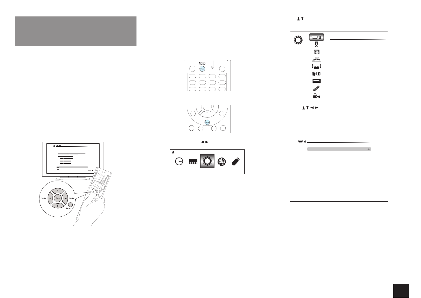
Operation
Press RCV on the remote controller.
1.
r Always press RCV first to change the remote
controller to RECEIVER mode (the mode to operate
this unit) since its mode may be changed to operate
another component.
Press Home to display the HOME menu.
2.
Select "Setup" with the / cursors and press Enter.
3.
HOME
Setup
Advanced Settings
Press / to select the desired menu, and then press
4.
Enter.
SETUP
With the / / / cursors, select the desired item to
5.
configure the settings.
r When "Enter" is displayed on the setting item, press
Enter.
1-1. Monitor Out
Monitor Out
Resolution
1. Input/Output Assign
1. Monitor Out
2. HDMI Input
3. Component Video Input
4. Composite Video Input
5. Digital Audio Input
MAIN
Through
Select which HDMI output you connected to TV. HDCP 2. 2 is available for MAIN output.
To save changes and finish the setting: Press Home to
exit.
19
Page 20

Advanced Settings
1.Input/Output Assign
Monitor Out
The video input signals input to the unit will be converted when they are output from the
HDMI OUT jack to the TV so that their resolution can match that of the TV used.
Setting Item Default Value Setting Details
Monitor Out MAIN Select the HDMI jack to be connected with the
TV.
"MAIN": When connecting the TV to the HDMI
OUT MAIN jack
"SUB": When connecting the TV to the HDMI
OUT SUB jack
r The resolution of the input signal does not
change when output through HDMI OUT
SUB jack.
"MAIN+SUB": When connecting to both the
MAIN and SUB jacks
r Video signals input to the composite video
input jack or the COMPONENT VIDEO input
jacks will be upconverted to HDMI signals
and then output from the HDMI output jack.
r If "MAIN+SUB" is selected
– Only "Through" or "Auto" can be selected
in "Resolution".
– The output resolution will differ between
"Through" and "Auto".
– The resolution of the input signal does not
change when output through HDMI OUT
SUB jack.
r The HDMI jack of this unit is compliant with
HDCP2.2 (HDMI OUT MAIN and HDMI IN3
jacks only).
Setting Item Default Value Setting Details
Resolution Through Specify the output resolution of the HDMI OUT
jacks. The image resolution of the unit will be
converted so that it can match the resolution
supported by the TV used.
"Through": The output resolution will be the
same as that of the input signals.
"Auto": The resolution will automatically be
converted according to the resolution supported
by the TV.
"480p (480p/576p)", "720p", "1680×720p",
"1080i", "1080p", "2560×1080p": Select the
desired resolution.
"4K": About four times as high resolution
as 1080p (3840×2160 or 4096×2160 pixels
depending on the resolution supported by the
connected TV)
"Source": The output resolution will be that
specified in "Picture Adjust" - "Resolution" in the
"4.|Source Setup" section.
r If "1080p" is selected, 1080p/24 input signals
will be output with an unchanged resolution.
r If the selected resolution is not supported by
the monitor, the video is output in the same
resolution as the input signal.
r If "4K" is selected, video signals may not be
output to some types of TV. For details, see
"Supported Video Resolution of HDMI OUT
MAIN/SUB Jacks" in "Reference Information".
r If "Monitor Out" is set to "SUB", this setting
will be set to "Through".
r You can check the video on the TV while
making this setting. Select the value with the
cursors and press ENTER. Press Return if
no video is displayed. (Except when "NET",
"USB" or "BLUETOOTH" is selected)
20
Page 21

Advanced Settings
HDMI Input
It is possible to change assignment of input selector buttons and the HDMI IN jacks.
Setting Item Default Value Setting Details
BD/DVD HDMI 1 "HDMI 1" to "HDMI 6": Desired HDMI IN jack
can be assigned to BD/DVD button. If you do not
assign a jack, select "-----". To select an HDMI IN
jack already assigned to another input selector,
change its setting to "-----" first.
CBL/SAT HDMI 2 "HDMI 1" to "HDMI 6": Desired HDMI IN jack can
be assigned to CBL/SAT button. If you do not
assign a jack, select "-----". To select an HDMI IN
jack already assigned to another input selector,
change its setting to "-----" first.
STB/DVR HDMI 3
(HDCP 2.2)
GAME HDMI 4 "HDMI 1" to "HDMI 6": Desired HDMI IN jack
PC HDMI 5 "HDMI 1" to "HDMI 6": Desired HDMI IN jack
AUX Front/MHL The setting cannot be changed.
TV/CD ----- "HDMI 1" to "HDMI 6": Desired HDMI IN jack
PHONO ----- "HDMI 1" to "HDMI 6": Desired HDMI IN jack
"HDMI 1" to "HDMI 6": Desired HDMI IN jack can
be assigned to STB/DVR button. If you do not
assign a jack, select "-----". To select an HDMI IN
jack already assigned to another input selector,
change its setting to "-----" first.
can be assigned to Game button. If you do not
assign a jack, select "-----". To select an HDMI IN
jack already assigned to another input selector,
change its setting to "-----" first.
can be assigned to PC button. If you do not
assign a jack, select "-----". To select an HDMI IN
jack already assigned to another input selector,
change its setting to "-----" first.
can be assigned to TV/CD button. If you do not
assign a jack, select "-----". To select an HDMI IN
jack already assigned to another input selector,
change its setting to "-----" first.
can be assigned to Phono button. If you do not
assign a jack, select "-----". To select an HDMI IN
jack already assigned to another input selector,
change its setting to "-----" first.
Component Video Input
CBL/SAT button is assigned to COMPONENT VIDEO IN jack as factory default setting. This
assignment can be changed if necessary. If you do not assign a jack, select "-----".
Setting Item Default Value Setting Details
BD/DVD ----- "COMPONENT": COMPONENT VIDEO IN jack is
assigned to BD/DVD button.
CBL/SAT COMPONENT "COMPONENT": COMPONENT VIDEO IN jack is
assigned to CBL/SAT button.
STB/DVR ----- "COMPONENT": COMPONENT VIDEO IN jack is
assigned to STB/DVR button.
GAME ----- "COMPONENT": COMPONENT VIDEO IN jack is
assigned to Game button.
PC ----- "COMPONENT": COMPONENT VIDEO IN jack is
assigned to PC button.
AUX ----- "COMPONENT": COMPONENT VIDEO IN jack is
assigned to AUX button.
TV/CD ----- "COMPONENT": COMPONENT VIDEO IN jack is
assigned to TV/CD button.
PHONO ----- "COMPONENT": COMPONENT VIDEO IN jack is
assigned to Phono button.
r When you convert video signals input to the COMPONENT VIDEO IN jacks and output them from
the HDMI OUT jack, set the output resolution of the player to 480i. If the input has 480p or higher
resolution, an error message will appear.
r When "1.|Input/Output Assign" - "Monitor Out" is set to "SUB", the 480i/576i component signals only
will be output with an unchanged resolution. Video will not be displayed if the TV does not support the
resolution.
r When "1.|Input/Output Assign" - "Monitor Out" is set to "MAIN" or "MAIN+SUB" and "Resolution" is
set to "Through", the 480i/576i component signals will be output with their resolution unchanged. So,
TV sets not supporting these resolutions will not be able to display video.
21
Page 22

Advanced Settings
Composite Video Input
It is possible to change assignment of input selector buttons and the COMPOSITE VIDEO
IN V1 to 3 jacks.
Setting Item Default Value Setting Details
BD/DVD ----- "VIDEO 1" to "VIDEO 3": Desired COMPOSITE
VIDEO IN V jack can be assigned to BD/DVD button.
If you do not assign a jack, select "-----".
CBL/SAT VIDEO 1 "VIDEO 1" to "VIDEO 3": Desired COMPOSITE
VIDEO IN V jack can be assigned to CBL/SAT button.
If you do not assign a jack, select "-----".
STB/DVR VIDEO 2 "VIDEO 1" to "VIDEO 3": Desired COMPOSITE
VIDEO IN V jack can be assigned to STB/DVR
button. If you do not assign a jack, select "-----".
GAME VIDEO 3 "VIDEO 1" to "VIDEO 3": Desired COMPOSITE
VIDEO IN V jack can be assigned to Game button. If
you do not assign a jack, select "-----".
PC ----- "VIDEO 1" to "VIDEO 3": Desired COMPOSITE
VIDEO IN V jack can be assigned to PC button. If you
do not assign a jack, select "-----".
AUX Front The setting cannot be changed.
TV/CD ----- "VIDEO 1" to "VIDEO 3": Desired COMPOSITE
VIDEO IN V jack can be assigned to TV/CD button. If
you do not assign a jack, select "-----".
PHONO ----- "VIDEO 1" to "VIDEO 3": Desired COMPOSITE
VIDEO IN V jack can be assigned to Phono button. If
you do not assign a jack, select "-----".
r When "1.|Input/Output Assign" - "Monitor Out" is set to "SUB", the 480i/576i composite signals only
will be output with an unchanged resolution. Video will not be displayed if the TV does not support the
resolution.
r When "1.|Input/Output Assign" - "Monitor Out" is set to "MAIN" or "MAIN+SUB" and "Resolution" is
set to "Through", the 480i/576i composite signals will be output with their resolution unchanged. So,
TV sets not supporting these resolutions will not be able to display video.
Digital Audio Input
It is possible to change assignment of input selector buttons and the DIGITAL IN COAXIAL
1 to 2/OPTICAL jacks.
Setting Item Default Value Setting Details
BD/DVD COAXIAL 1 "COAXIAL 1", "COAXIAL 2", "OPTICAL": Desired
DIGITAL IN jack can be assigned to BD/DVD button.
If you do not assign a jack, select "-----".
CBL/SAT COAXIAL 2 "COAXIAL 1", "COAXIAL 2", "OPTICAL": Desired
DIGITAL IN jack can be assigned to CBL/SAT button.
If you do not assign a jack, select "-----".
STB/DVR ----- "COAXIAL 1", "COAXIAL 2", "OPTICAL": Desired
DIGITAL IN jack can be assigned to STB/DVR button.
If you do not assign a jack, select "-----".
GAME ----- "COAXIAL 1", "COAXIAL 2", "OPTICAL": Desired
DIGITAL IN jack can be assigned to Game button. If
you do not assign a jack, select "-----".
PC ----- "COAXIAL 1", "COAXIAL 2", "OPTICAL": Desired
DIGITAL IN jack can be assigned to PC button. If you
do not assign a jack, select "-----".
AUX ----- "COAXIAL 1", "COAXIAL 2", "OPTICAL": Desired
DIGITAL IN jack can be assigned to AUX button. If
you do not assign a jack, select "-----".
TV/CD OPTICAL "COAXIAL 1", "COAXIAL 2", "OPTICAL": Desired
DIGITAL IN jack can be assigned to TV/CD button. If
you do not assign a jack, select "-----".
PHONO ----- "COAXIAL 1", "COAXIAL 2", "OPTICAL": Desired
DIGITAL IN jack can be assigned to Phono button. If
you do not assign a jack, select "-----".
r Supported sampling rates for PCM signals (stereo, mono) from a digital input are 32|kHz/44.1|kHz/
48|kHz/88.2|kHz/96|kHz/16|bit, 20|bit, 24|bit.
22
Page 23

Advanced Settings
2.Speaker Setup
Allows you to change the speaker configuration such as presence or not of subwoofer,
crossover frequency, and so on. Settings are automatically configured if you use the
Automatic Speaker Setup.
Furthermore, this setting cannot be selected if headphones are connected or audio is
output from the speakers of the TV.
Speaker Settings
Change the impedance of the connected speakers, the type of front speaker connection
and height speaker type.
Setting Item Default Value Setting Details
Speaker
Impedance
(Australian and
Asian models)
Front Speakers
Type
Height Speakers
Type
6ohms Set the impedance of the connected speakers.
"4ohms": When any of the connected speakers have
4 ŝ or more to less than 6 ŝ impedance
"6ohms": When the connected speakers all have 6 ŝ
or more impedance
Normal Select the type of front speaker connection.
"Normal": When front speakers are connected in a
normal manner
"Bi-Amp": When front speakers are bi-amp
connected
Not Use Set the speaker type if height speakers are
connected to the SPEAKERS BACK or HEIGHT
terminals. Select from the following options
according to the type and layout of the connected
speakers: "Not Use", "Front High", "Top Front", "Top
Middle", "Dolby Enabled Speaker (Front)", or "Dolby
Enabled Speaker (Surround)".
r If "Front Speakers Type" is set to "Bi-Amp", this
setting will be set to "Not Use".
r "Dolby Enabled Speaker (Surround)" cannot be
selected if "Speaker Configuration" - "Surround"
is set to "None".
Setting Item Default Value Setting Details
Powered Zone 2 No Set presence of speaker terminal connection of
Zone 2.
"Yes": When speakers are connected to ZONE 2
speaker terminals
"No": When speakers are not connected to ZONE 2
speaker terminals
r If "Front Speakers Type" is set to "Bi-Amp", this
setting will be set to "No".
r For impedance, check the indications on the back of the speakers or their instruction manual.
Speaker Configuration
Allows you to change the speaker configuration such as presence or not of each speaker,
crossover frequency, and so on. Settings are automatically configured if you use the
Automatic Speaker Setup. Audio will not be output while you are making this setting.
Setting Item Default Value Setting Details
Subwoofer Yes Set whether a subwoofer is connected or not.
"Yes": When subwoofer is connected
"No": When subwoofer is not connected
Front 100Hz Select the crossover frequency from "40Hz" to
"200Hz" to start outputting frequencies for each
channel.
"Full Band": Full band will be output.
r "Front" will be fixed to "Full Band" if "Subwoofer"
is set to "No", and the bass frequencies of the
other channels will be output from the front
speakers. To make the settings, refer to the
instruction manual of the speakers used.
Center 100Hz Select the crossover frequency from "40Hz" to
"200Hz" to start outputting frequencies for each
channel.
"Full Band": Full band will be output.
"None": When no compatible speaker is connected
r "Full Band" can only be set if "Front" is set to "Full
Band".
23
Page 24

Advanced Settings
Setting Item Default Value Setting Details
Surround 100Hz Select the crossover frequency from "40Hz" to
"200Hz" to start outputting bass frequencies for
each channel.
"Full Band": Full band will be output.
"None": When no compatible speaker is connected
r "Full Band" can only be set if "Front" is set to "Full
Band".
Back 100Hz Select the crossover frequency from "40Hz" to
"200Hz" to start outputting bass frequencies for
each channel.
"Full Band": Full band will be output.
"None": When no compatible speaker is connected
r In any of the following cases, this setting will be
set to "None".
– "Surround" is set to "None".
– "Speaker Settings" - "Front Speakers Type" is
set to "Bi-Amp".
– "Speaker Settings" - "Height Speakers Type" is
set to other than "Not Use".
– "Speaker Settings" - "Powered Zone 2" is set
to "Yes" and also Zone2 is set to on.
r "Full Band" can only be set if "Surround" is set to
"Full Band".
Back ch 2ch Select the number of channels of the connected
surround back speaker.
"1ch": When one speaker is connected (Connect to
the BACK or HEIGHT L terminal)
"2ch": When two speakers are connected
r The setting cannot be changed if "Back" is set to
"None".
Setting Item Default Value Setting Details
Height None Select the crossover frequency from "40Hz" to
"200Hz" to start outputting bass frequencies for
each channel.
"Full Band": Full band will be output.
r In any of the following cases, this setting will be
set to "None".
– "Speaker Settings" - "Height Speakers Type" is
set to "Not Use".
– "Speaker Settings" - "Front Speakers Type" is
set to "Bi-Amp".
– "Speaker Settings" - "Powered Zone 2" is set
to "Yes" and also Zone2 is set to on.
r If any type is selected in "Speaker Settings" -
"Height Speakers Type", this setting will be set to
"100Hz" as default value. In this case, this setting
cannot be set to "None".
r "Full Band" can only be set if "Front" is set to "Full
Band".
LPF of LFE 120Hz Set the low-pass filter for LFE (low-frequency effect)
signals in order to pass lower frequency signals than
the set value and thus cancel unwanted noises. The
low-pass filter will be effective only on sources with
LFE channel.
Set a frequency from "80Hz" to "120Hz".
"Off": Do not use this function
Double Bass ----- Boost bass output by feeding bass sounds from
the front left and right, and center speakers to the
subwoofer.
"On": Bass output will be boosted.
"Off": Bass output will not be boosted.
r The setting will not automatically be configured
even if you performed the automatic speaker
setup.
r The setting cannot be changed if "Subwoofer" is
set to "No" or if "Front" is set to other than "Full
Band".
24
Page 25

Advanced Settings
Speaker Distance
Set the distance from each speaker to the listening position. Settings are automatically
configured if you use the automatic speaker setup.
Setting Item Default Value Setting Details
Unit feet/meters Specify the unit of distance for configuring
settings.
"feet": When setting in feet (0.1ft to 30.0ft, in
increments of 0.1ft)
"meters": When setting in meters (0.03m to
9.00m, in increments of 0.03m)
Front Left 12.0ft/3.60m Specify the distance between each speaker and
the listening position.
Center 12.0ft/3.60m Specify the distance between each speaker and
the listening position.
Front Right 12.0ft/3.60m Specify the distance between each speaker and
the listening position.
Surround Right 7.0ft/2.10m Specify the distance between each speaker and
the listening position.
Back Right 7.0ft/2.10m Specify the distance between each speaker and
the listening position.
r The setting is not displayed if "Speaker
Configuration" - "Back" is set to other than
"None" and also "Back ch" is set to "1ch".
r This setting cannot be changed in any of the
following cases.
– "Speaker Settings" - "Front Speakers Type"
is set to "Bi-Amp".
– "Speaker Settings" - "Powered Zone 2" is
set to "Yes" and also Zone2 is set to on.
Back Left 7.0ft/2.10m Specify the distance between each speaker and
the listening position.
r The setting is not displayed if "Speaker
Configuration" - "Back" is set to other than
"None" and also "Back ch" is set to "1ch".
r This setting cannot be changed in any of the
following cases.
– "Speaker Settings" - "Front Speakers Type"
is set to "Bi-Amp".
– "Speaker Settings" - "Powered Zone 2" is
set to "Yes" and also Zone2 is set to on.
Setting Item Default Value Setting Details
Back 7.0ft/2.10m Specify the distance between each speaker and
the listening position.
r The setting is displayed if "Speaker
Configuration" - "Back" is set to other than
"None" and also "Back ch" is set to "1ch".
r This setting cannot be changed when
"Speaker Settings" - "Powered Zone 2" is set
to "Yes" and Zone 2 is turned on.
Surround Left 7.0ft/2.10m Specify the distance between each speaker and
the listening position.
Subwoofer 12.0ft/3.60m Specify the distance between each speaker and
the listening position.
Height Left 9.0ft/2.70m Specify the distance between each speaker and
the listening position.
r This setting cannot be changed in any of the
following cases.
– "Speaker Settings" - "Height Speakers
Type" is set to "Not Use".
– "Speaker Settings" - "Powered Zone 2" is
set to "Yes" and also Zone2 is set to on.
Height Right 9.0ft/2.70m Specify the distance between each speaker and
the listening position.
r This setting cannot be changed in any of the
following cases.
– "Speaker Settings" - "Height Speakers
Type" is set to "Not Use".
– "Speaker Settings" - "Powered Zone 2" is
set to "Yes" and also Zone2 is set to on.
r When the speaker is set to "No" or "None" in "Speaker Configuration", the settings for "Speaker
Distance" cannot be changed.
r Default values vary depending on the regions.
25
Page 26

Advanced Settings
Level Calibration
Adjust the level of each speaker with the built-in test tone. Settings are automatically
configured if you use the Automatic Speaker Setup.
Setting Item Default Value Setting Details
Front Left 0dB Select a value between "-12dB" to "+12dB". A
test tone will be output each time you change
the value. Select the desired level.
Center 0dB Select a value between "-12dB" to "+12dB". A
test tone will be output each time you change
the value. Select the desired level.
Front Right 0dB Select a value between "-12dB" to "+12dB". A
test tone will be output each time you change
the value. Select the desired level.
Surround Right 0dB Select a value between "-12dB" to "+12dB". A
test tone will be output each time you change
the value. Select the desired level.
Back Right 0dB Select a value between "-12dB" to "+12dB". A
test tone will be output each time you change
the value. Select the desired level.
r The setting is not displayed if "Speaker
Configuration" - "Back" is set to other than
"None" and also "Back ch" is set to "1ch".
r This setting cannot be changed in any of the
following cases.
– "Speaker Settings" - "Front Speakers
Type" is set to "Bi-Amp".
– "Speaker Settings" - "Powered Zone 2" is
set to "Yes" and also Zone2 is set to on.
Back Left 0dB Select a value between "-12dB" to "+12dB". A
test tone will be output each time you change
the value. Select the desired level.
r The setting is not displayed if "Speaker
Configuration" - "Back" is set to other than
"None" and also "Back ch" is set to "1ch".
r This setting cannot be changed in any of the
following cases.
– "Speaker Settings" - "Front Speakers
Type" is set to "Bi-Amp".
– "Speaker Settings" - "Powered Zone 2" is
set to "Yes" and also Zone2 is set to on.
Setting Item Default Value Setting Details
Back 0dB Select a value between "-12dB" to "+12dB". A
test tone will be output each time you change
the value. Select the desired level.
r The setting is displayed if "Speaker
Configuration" - "Back" is set to other than
"None" and also "Back ch" is set to "1ch".
r This setting cannot be changed when
"Speaker Settings" - "Powered Zone2" is set
to "Yes" and Zone 2 is turned on.
Surround Left 0dB Select a value between "-12dB" to "+12dB". A
test tone will be output each time you change
the value. Select the desired level.
Subwoofer 0dB Select a value between "-15dB" to "+12dB". A
test tone will be output each time you change
the value. Select the desired level.
Height Left 0dB Select a value between "-12dB" to "+12dB". A
test tone will be output each time you change
the value. Select the desired level.
r This setting cannot be changed in any of the
following cases.
– "Speaker Settings" - "Height Speakers
Type" is set to "Not Use".
– "Speaker Settings" - "Powered Zone 2" is
set to "Yes" and also Zone2 is set to on.
Height Right 0dB Select a value between "-12dB" to "+12dB". A
test tone will be output each time you change
the value. Select the desired level.
r This setting cannot be changed in any of the
following cases.
– "Speaker Settings" - "Height Speakers
Type" is set to "Not Use".
– "Speaker Settings" - "Powered Zone 2" is
set to "Yes" and also Zone2 is set to on.
r In the following cases, the settings for "Level Calibration" cannot be changed:
– The speaker is set to "No" or "None" in "Speaker Configuration".
– Mute (MUTING) is set.
26
Page 27

Advanced Settings
3.Audio Adjust
Configure various settings related to sound, such as settings for listening to multiplex audio
or multilingual TV broadcasts and sound field settings for listening modes.
Multiplex/Mono
Setting Item Default Value Setting Details
Multiplex
Input Channel
Mono
Input Channel
Main Set the audio channel or language to be output
when playing multiplex audio or multilingual TV
broadcasts etc.
"Main": Main channel only
"Sub": Sub channel only
"Main/Sub": Main and sub channels will be
output at the same time.
r If multiplex audio is being played, "1+1" will
be displayed when Display on the main unit is
pressed.
Left+Right Set the input channel to use for playing any 2
ch digital source such as Dolby Digital, or 2-ch
analog/PCM source in the Mono listening mode.
"Left": Left channel only
"Right": Right channel only
"Left+Right": Left and right channels
Dolby
Make the settings for Dolby listening mode.
DTS
Make the settings for DTS Neo:6 Music listening mode.
Setting Item Default Value Setting Details
Neo:6 Music
Center Image
2 Adjust the width of the sound field of the front
channel when playing in the DTS Neo:6 Music
listening mode.
"0" to "5": Selecting a smaller value brings the
sound field of the front channel to the center
while selecting a larger value spreads the sound
field of the front channel to left and right.
Theater-Dimensional
Make the settings for Theater-Dimensional mode.
Setting Item Default Value Setting Details
Listening Angle Wide Set the angle of the front left and right speakers
relative to the listening position when playing in
the Theater-Dimensional listening mode.
"Narrow": Less than 30°
"Wide": Greater than 30°
r Values recommended for "Listening Angle" are: 20° when "Narrow" is selected and 40° when "Wide"
is selected.
Setting Item Default Value Setting Details
Loudness
Management
Center Spread Off Adjust the width of the front sound field created
On Enable the Late Night function that allows
you to enjoy surround sound of Dolby TrueHD
playback even in low volume.
"On": Use this function
"Off": Do not use this function
during Dolby Surround listening mode playback.
"On": The sound field is spread to left and right.
"Off": The sound field is centralized.
r The setting will be fixed to "Off" if "Speaker
Configuration" - "Center" is set to "None".
27
Page 28

Advanced Settings
4.Source Setup
Adjust the volume level difference among the multiple devices connected to this unit,
rename an input selector, or adjust the image quality. The setting can be separately set to
each input selector button. When you select a desired input to check the video or audio,
start playback of the connected device.
AccuEQ Room Calibration
Setting Item Default Value Setting Details
AccuEQ Room
Calibration
Off Enable/disable the sound field set in automatic
speaker setup
"On": Enable this function
"Off": Disable this function
r In the following cases, the setting cannot be
changed:
– Automatic speaker setup is not performed.
– Headphones are connected.
IntelliVolume
Setting Item Default Value Setting Details
IntelliVolume 0dB Adjust the volume level difference between the
devices connected to the unit. Select a value
between "-12dB" to "+12dB". Set a negative
value if the volume of the target device is larger
than the others and a positive value if smaller.
r This function is not effective in Zone 2.
Name Edit
Set an easy name to each input. The set name will be shown on the main unit display.
Setting Item Default Value Setting Details
Name Input name 1. Select a character or symbol with the
cursors and press Enter.
Repeat it to input 10 or less characters.
"Shift": Switches between upper and
lower cases. (Pressing +10 on the remote
controller also toggles between upper and
lower cases.)
" " ": Moves the cursor to the arrow
"
direction.
"Back Space": Removes a character on the
left of the cursor.
"Space": Puts a space.
r Pressing CLR on the remote controller
will remove all the input characters.
2. After inputting, select "OK" with the cursors
and press Enter.
The input name will be saved.
r To name a preset radio station, press Tuner on the remote controller, select AM/FM and select the
preset number.
r It cannot be set if the input is "NET", "USB" or "BLUETOOTH".
28
Page 29

Advanced Settings
Picture Adjust
Adjust the image quality. (Possible only when the video player is connected to the HDMI
OUT MAIN jack) If you adjust it by checking the video, press Enter. Press Return to return
the screen to the previous status.
Setting Item Default Value Setting Details
Wide Mode Auto Set the aspect ratio.
"Auto": The aspect ratio will automatically be set
according to the input signals and the monitor
output setting.
"4:3":
"Full":
"Zoom":
"Wide Zoom":
r When a 3D or 4K video source is input, this
setting is set to "Full". Furthermore, for some
resolutions, this setting may be disabled and
set to "Full".
Setting Item Default Value Setting Details
Picture Mode Custom An appropriate image quality setting for cinema
or game can be selected. You can also adjust
each item to obtain your favorite image quality.
"Custom": The items from "Game Mode" to "Blue
Contrast" can be adjusted as desired.
"ISF Day": Select when the room is bright.
"ISF Night": Select when the room is dark.
"Cinema": When the video source is cinema
"Game": When the video source is game
"Standard": The resolution will be changed but
the image quality will not be adjusted.
"Bypass": Both the resolution and image quality
will not be adjusted.
r If you select "Bypass", the on-screen display
function will be disabled.
r The receiver has been designed to
incorporate setup and calibration standards
established by the Imaging Science
Foundation (ISF). The ISF has developed
carefully crafted, industry-recognized
standards for optimal video performance
and has implemented a training program
for technicians and installers to use these
standards to obtain optimal picture quality
from the receiver. Accordingly, Onkyo
recommends that setup and calibration be
performed by an ISF Certified installation
technician.
Game Mode Off Change to the setting suitable for game. Also
correct the delay of video signals of the game
console if any.
"On": Use this function
"Off": Do not use this function
r If you select "On", the delay will be corrected
but the image quality will be lower.
r The setting will be fixed to "Off" if
"Resolution" is set to "4K".
Film Mode Auto Change to the setting suitable for film.
"Auto": Image processing suitable for film will be
executed.
"Video": "Film Mode" will not be applied and the
input signals will be processed as video source.
29
Page 30

Advanced Settings
Setting Item Default Value Setting Details
Edge
Enhancement
Off Adjust the sharpness of the outline of image.
Select from "Off", "Low", "Mid" (Middle), and
"High".
r The setting will be fixed to "Off" if "Game
Mode" is set to "On".
r When the horizontal resolution of the output
video is 2,000 TV lines or more, this setting is
set to "Off".
Noise Reduction Off Reduces the noise of the screen. Select from
"Off", "Low", "Mid" (Middle), and "High".
r The setting will be fixed to "Off" if "Game
Mode" is set to "On".
Resolution Through Adjust the output resolution of the HDMI OUT
jacks. The image resolution of the unit will be
converted so that it can match the resolution
supported by the TV used.
"Through": The output resolution will be the
same as that of the input signals.
"Auto": The resolution will automatically be
converted to the resolution supported by the TV.
"480p (480p/576p)", "720p", "1680×720p",
"1080i", "1080p", "2560×1080p": Select the
desired resolution.
"4K": About four times as high resolution
as 1080p (3840×2160 or 4096×2160 pixels
depending on the resolution supported by the
connected TV)
r The setting can be selected only when
"Source" is selected in "1.
|
Input/Output
Assign" - "Monitor Out" - "Resolution".
r If "4K" is selected, video signals may not be
output to some types of TV. For details, see
"Supported Video Resolution of HDMI OUT
MAIN/SUB Jacks" in "Reference Information".
Brightness 0 Adjust brightness of the screen. Select a value
between "-50" to "+50".
Contrast 0 Adjust contrast of the screen. Select a value
between "-50" to "+50".
Hue 0 Correct hue of the screen. Select a value
between "-50" to "+50".
Setting Item Default Value Setting Details
Saturation 0 Adjust saturation of the screen. Select a value
between "-50" to "+50".
Color Temperature Normal Set color temperature of the screen. Select from
"Warm", "Normal" and "Cool".
Gamma 0 Adjust the relative relation between the R (red),
G (green) and B (blue) data signals of the input
image and those of the output image. Select a
value between "-3" to "+3".
Red Brightness 0 Adjust the brightness of red of the screen. Select
a value between "-50" to "+50".
Red Contrast 0 Adjust the contrast of red of the screen. Select a
value between "-50" to "+50".
Green Brightness 0 Adjust the brightness of green of the screen.
Select a value between "-50" to "+50".
Green Contrast 0 Adjust the contrast of green of the screen.
Select a value between "-50" to "+50".
Blue Brightness 0 Adjust the brightness of blue of the screen.
Select a value between "-50" to "+50".
Blue Contrast 0 Adjust the contrast of blue of the screen. Select
a value between "-50" to "+50".
r In the following cases, the settings for "Picture Adjust" cannot be changed:
– "NET", "USB" or "BLUETOOTH" is selected.
– "1.|Input/Output Assign" - "Monitor Out" is set to "SUB".
r Press CLR on the remote controller if you return all the settings from "Game Mode" through "Blue
Contrast" to their default value.
30
Page 31

Advanced Settings
Audio Selector
Make the audio input setting. The setting can be separately set to each input selector
button. Select the input selector to configure.
Setting Item Default Value Setting Details
Audio Selector – Allows you to select prior input source.
"ARC": When giving priority to input signal from
ARC compatible TV.
r The setting can be selected only when
"7.|Hardware Setup" - "HDMI" - "Audio Return
Channel" is set to "Auto" and also the "TV/CD"
input is selected.
"HDMI": When giving priority to input signal from
HDMI jacks
r The setting can be selected only when the
input is assigned to the HDMI IN jack in the
"HDMI Input" setting.
"COAXIAL" (Coaxial input): When giving priority
to input signal from COAXIAL IN jacks.
r The setting can be selected only when the
input is assigned to the COAXIAL jack in the
"Digital Audio Input" setting.
"OPTICAL" (Optical input): When giving priority to
input signal from OPTICAL IN jacks.
r The setting can be selected only when the
input is assigned to the OPTICAL jack in the
"Digital Audio Input" setting.
"Analog": To always output analog audio
independently of the input signal
Fixed Mode Off Specify an input signal when "HDMI", "COAXIAL
(Coaxial input)", or "OPTICAL (Optical input)" is
selected for "Audio Selector". Set this item if noise
is produced, or truncation occurs at the beginning
of a track that follows a gap when playing PCM or
DTS sources.
"Off": To play an analog signal when there is no
digital signal.
"PCM": To fix the input source to PCM (except for
Multichannel PCM).
"DTS": To fix the input source to DTS (except for
DTS-HD).
r Changing "Audio Selector" changes the
setting to "Off".
5.Listening Mode Preset
You can preset your favorite listening mode to each input. (For example, you can always
apply straight decode to the Dolby TrueHD source of Blu-ray Disc to play it in unchanged
sound field.)
When the list of input sources is displayed, set the signal type and listening mode.
Although it is possible to select the listening mode during playback, the selected mode will
be reset when the unit enters standby mode.
Setting Item Default Value Setting Details
Analog/PCM All Ch Stereo Set the listening mode for playing PCM signals
of CD and analog signals of record and cassette
tape.
Mono/Multiplex
Source
2ch Source Dolby
Dolby D/Dolby
D Plus/TrueHD
DTS/DTS-ES/DTS-HDStraight
Other Multich Source Dolby
r Available listening modes vary depending on the input signal.
r Setting "Last Valid" will always select the last selected mode.
r Only "Analog" can be set to the "TUNER" input.
r "Digital" and "TrueHD" can be set to the "NET" and "USB" inputs.
r Only "Digital" can be set to the "BLUETOOTH" input.
Full Mono Set the listening mode for playing Dolby Digital
and other digital signals recorded in monaural or
multiplex audio.
Set the listening mode for playing Dolby Digital
Surround
Dolby
Surround
and other digital signals recorded in 2 channels.
Set the listening mode for playing Dolby Digital,
Dolby Digital Plus and Dolby TrueHD signals.
Set the listening mode for playing digital audio
Decode
signals in DTS and DTS-HD High Resolution
formats. Select the listening mode specified for
Blu-ray or such other DTS-HD Master Audio
source.
Set the listening mode for playing DSD signals
Surround
of DVD-Audio and Super Audio CD that are input
from HDMI IN jack.
r The setting cannot be changed when "PHONO", "TUNER", "NET", "USB", or "BLUETOOTH" input is
selected.
31
Page 32

Advanced Settings
6.Miscellaneous
Volume Setup
Make the detailed volume setting of the unit.
Setting Item Default Value Setting Details
Maximum Volume Off Set the maximum value to avoid too high volume.
Select a value from "Off", "30" to "79".
Power On Volume Last Set the volume level of when the power is turned
on. Select a value from "Last" (Volume level
before entering standby mode), "Min", "1" to "79"
and "Max".
r You cannot set a higher value than that of
"Maximum Volume".
Headphone Level 0dB Adjust the volume level difference between
speakers and headphones. Select a value
between "-12dB" to "+12dB".
OSD Setup
Make the setting of on-screen display function that can display the setting menu screen,
volume operation screen and the like on the TV.
Setting Item Default Value Setting Details
On Screen Display On Set whether or not to display the operation
screen on the TV.
"On": The operation screen will be displayed on
the TV.
"Off": The operation screen will not be displayed
on the TV.
r The operation screen may not be displayed
depending on the input signal even if "On"
is selected. If the operation screen is not
displayed, change the resolution of the
connected device.
Language English Select the on-screen display language.
Screen Saver 3min Set the time to start the screen saver. Select a
value from "3min", "5min", "10min" and "Off".
12V Trigger A Setup
You can enable power link operation when you connect the unit and the external devices
equipped with 12V trigger input jack. When the desired input is selected, power link
operation will be activated with a control signal of maximum 12 V/150 mA output from the
12V trigger output jack.
Setting Item Default Value Setting Details
Delay 0sec Set after how many seconds the 12V trigger
output will occur in response to the unit's
operation. As some devices cause a large
current when they turn on, delay the output if
such devices are connected. Select a value
between "0sec" to "3sec".
BD/DVD Main Set the 12V trigger output setting to each
input. Setting should be made for each 12V
TRIGGER OUT jack.
"Off": No output
"Main": Will be output when selected as input
source of main room playback
"Zone2": Will be output when selected as
input source of Zone 2 playback
"Main/Zone2": Will be output when selected as
input source of main room or Zone 2 playback
CBL/SAT Main Set the 12V trigger output setting to each
input. Setting should be made for each 12V
TRIGGER OUT jack.
"Off": No output
"Main": Will be output when selected as input
source of main room playback
"Zone2": Will be output when selected as
input source of Zone 2 playback
"Main/Zone2": Will be output when selected as
input source of main room or Zone 2 playback
32
Page 33

Advanced Settings
Setting Item Default Value Setting Details
STB/DVR Main Set the 12V trigger output setting to each
input. Setting should be made for each 12V
TRIGGER OUT jack.
"Off": No output
"Main": Will be output when selected as input
source of main room playback
"Zone2": Will be output when selected as
input source of Zone 2 playback
"Main/Zone2": Will be output when selected as
input source of main room or Zone 2 playback
GAME Main Set the 12V trigger output setting to each
input. Setting should be made for each 12V
TRIGGER OUT jack.
"Off": No output
"Main": Will be output when selected as input
source of main room playback
"Zone2": Will be output when selected as
input source of Zone 2 playback
"Main/Zone2": Will be output when selected as
input source of main room or Zone 2 playback
PC Main Set the 12V trigger output setting to each
input. Setting should be made for each 12V
TRIGGER OUT jack.
"Off": No output
"Main": Will be output when selected as input
source of main room playback
"Zone2": Will be output when selected as
input source of Zone 2 playback
"Main/Zone2": Will be output when selected as
input source of main room or Zone 2 playback
AUX Main Set the 12V trigger output setting to each
input. Setting should be made for each 12V
TRIGGER OUT jack.
"Off": No output
"Main": Will be output when selected as input
source of main room playback
"Zone2": Will be output when selected as
input source of Zone 2 playback
"Main/Zone2": Will be output when selected as
input source of main room or Zone 2 playback
Setting Item Default Value Setting Details
TV/CD Main Set the 12V trigger output setting to each
input. Setting should be made for each 12V
TRIGGER OUT jack.
"Off": No output
"Main": Will be output when selected as input
source of main room playback
"Zone2": Will be output when selected as
input source of Zone 2 playback
"Main/Zone2": Will be output when selected as
input source of main room or Zone 2 playback
PHONO Main Set the 12V trigger output setting to each
input. Setting should be made for each 12V
TRIGGER OUT jack.
"Off": No output
"Main": Will be output when selected as input
source of main room playback
"Zone2": Will be output when selected as
input source of Zone 2 playback
"Main/Zone2": Will be output when selected as
input source of main room or Zone 2 playback
TUNER Main Set the 12V trigger output setting to each
input. Setting should be made for each 12V
TRIGGER OUT jack.
"Off": No output
"Main": Will be output when selected as input
source of main room playback
"Zone2": Will be output when selected as
input source of Zone 2 playback
"Main/Zone2": Will be output when selected as
input source of main room or Zone 2 playback
NET Main Set the 12V trigger output setting to each
input. Setting should be made for each 12V
TRIGGER OUT jack.
"Off": No output
"Main": Will be output when selected as input
source of main room playback
"Zone2": Will be output when selected as
input source of Zone 2 playback
"Main/Zone2": Will be output when selected as
input source of main room or Zone 2 playback
33
Page 34

Advanced Settings
Setting Item Default Value Setting Details
USB Main Set the 12V trigger output setting to each
input. Setting should be made for each 12V
TRIGGER OUT jack.
"Off": No output
"Main": Will be output when selected as input
source of main room playback
"Zone2": Will be output when selected as
input source of Zone 2 playback
"Main/Zone2": Will be output when selected as
input source of main room or Zone 2 playback
BLUETOOTH Main Set the 12V trigger output setting to each
input. Setting should be made for each 12V
TRIGGER OUT jack.
"Off": No output
"Main": Will be output when selected as input
source of main room playback
"Zone2": Will be output when selected as
input source of Zone 2 playback
"Main/Zone2": Will be output when selected as
input source of main room or Zone 2 playback
12V Trigger B Setup
You can enable power link operation when you connect the unit and the external devices
equipped with 12V trigger input jack. When the desired input is selected, power link
operation will be activated with a control signal of maximum 12 V/25 mA output from the
12V trigger output jack.
Setting Item Default Value Setting Details
Delay 1sec Set after how many seconds the 12V trigger
output will occur in response to the unit's
operation. As some devices cause a large
current when they turn on, delay the output if
such devices are connected. Select a value
between "0sec" to "3sec".
Setting Item Default Value Setting Details
BD/DVD Main/Zone 2 Set the 12V trigger output setting to each
input. Setting should be made for each 12V
TRIGGER OUT jack.
"Off": No output
"Main": Will be output when selected as input
source of main room playback
"Zone2": Will be output when selected as
input source of Zone 2 playback
"Main/Zone2": Will be output when selected as
input source of main room or Zone 2 playback
CBL/SAT Main/Zone 2 Set the 12V trigger output setting to each
input. Setting should be made for each 12V
TRIGGER OUT jack.
"Off": No output
"Main": Will be output when selected as input
source of main room playback
"Zone2": Will be output when selected as
input source of Zone 2 playback
"Main/Zone2": Will be output when selected as
input source of main room or Zone 2 playback
STB/DVR Main/Zone 2 Set the 12V trigger output setting to each
input. Setting should be made for each 12V
TRIGGER OUT jack.
"Off": No output
"Main": Will be output when selected as input
source of main room playback
"Zone2": Will be output when selected as
input source of Zone 2 playback
"Main/Zone2": Will be output when selected as
input source of main room or Zone 2 playback
GAME Main/Zone 2 Set the 12V trigger output setting to each
input. Setting should be made for each 12V
TRIGGER OUT jack.
"Off": No output
"Main": Will be output when selected as input
source of main room playback
"Zone2": Will be output when selected as
input source of Zone 2 playback
"Main/Zone2": Will be output when selected as
input source of main room or Zone 2 playback
34
Page 35

Advanced Settings
Setting Item Default Value Setting Details
PC Main/Zone 2 Set the 12V trigger output setting to each
input. Setting should be made for each 12V
TRIGGER OUT jack.
"Off": No output
"Main": Will be output when selected as input
source of main room playback
"Zone2": Will be output when selected as
input source of Zone 2 playback
"Main/Zone2": Will be output when selected as
input source of main room or Zone 2 playback
AUX Main/Zone 2 Set the 12V trigger output setting to each
input. Setting should be made for each 12V
TRIGGER OUT jack.
"Off": No output
"Main": Will be output when selected as input
source of main room playback
"Zone2": Will be output when selected as
input source of Zone 2 playback
"Main/Zone2": Will be output when selected as
input source of main room or Zone 2 playback
TV/CD Main/Zone 2 Set the 12V trigger output setting to each
input. Setting should be made for each 12V
TRIGGER OUT jack.
"Off": No output
"Main": Will be output when selected as input
source of main room playback
"Zone2": Will be output when selected as
input source of Zone 2 playback
"Main/Zone2": Will be output when selected as
input source of main room or Zone 2 playback
PHONO Main/Zone 2 Set the 12V trigger output setting to each
input. Setting should be made for each 12V
TRIGGER OUT jack.
"Off": No output
"Main": Will be output when selected as input
source of main room playback
"Zone2": Will be output when selected as
input source of Zone 2 playback
"Main/Zone2": Will be output when selected as
input source of main room or Zone 2 playback
Setting Item Default Value Setting Details
TUNER Main/Zone 2 Set the 12V trigger output setting to each
input. Setting should be made for each 12V
TRIGGER OUT jack.
"Off": No output
"Main": Will be output when selected as input
source of main room playback
"Zone2": Will be output when selected as
input source of Zone 2 playback
"Main/Zone2": Will be output when selected as
input source of main room or Zone 2 playback
NET Main/Zone 2 Set the 12V trigger output setting to each
input. Setting should be made for each 12V
TRIGGER OUT jack.
"Off": No output
"Main": Will be output when selected as input
source of main room playback
"Zone2": Will be output when selected as
input source of Zone 2 playback
"Main/Zone2": Will be output when selected as
input source of main room or Zone 2 playback
USB Main/Zone 2 Set the 12V trigger output setting to each
input. Setting should be made for each 12V
TRIGGER OUT jack.
"Off": No output
"Main": Will be output when selected as input
source of main room playback
"Zone2": Will be output when selected as
input source of Zone 2 playback
"Main/Zone2": Will be output when selected as
input source of main room or Zone 2 playback
BLUETOOTH Main/Zone 2 Set the 12V trigger output setting to each
input. Setting should be made for each 12V
TRIGGER OUT jack.
"Off": No output
"Main": Will be output when selected as input
source of main room playback
"Zone2": Will be output when selected as
input source of Zone 2 playback
"Main/Zone2": Will be output when selected as
input source of main room or Zone 2 playback
35
Page 36

Advanced Settings
12V Trigger C Setup
You can enable power link operation when you connect the unit and the external devices
equipped with 12V trigger input jack. When the desired input is selected, power link
operation will be activated with a control signal of maximum 12 V/25 mA output from the
12V trigger output jack.
Setting Item Default Value Setting Details
Delay 2sec Set after how many seconds the 12V trigger
output will occur in response to the unit's
operation. As some devices cause a large
current when they turn on, delay the output if
such devices are connected. Select a value
between "0sec" to "3sec".
BD/DVD Zone 2 Set the 12V trigger output setting to each
input. Setting should be made for each 12V
TRIGGER OUT jack.
"Off": No output
"Main": Will be output when selected as input
source of main room playback
"Zone2": Will be output when selected as
input source of Zone 2 playback
"Main/Zone2": Will be output when selected as
input source of main room or Zone 2 playback
CBL/SAT Zone 2 Set the 12V trigger output setting to each
input. Setting should be made for each 12V
TRIGGER OUT jack.
"Off": No output
"Main": Will be output when selected as input
source of main room playback
"Zone2": Will be output when selected as
input source of Zone 2 playback
"Main/Zone2": Will be output when selected as
input source of main room or Zone 2 playback
Setting Item Default Value Setting Details
STB/DVR Zone 2 Set the 12V trigger output setting to each
input. Setting should be made for each 12V
TRIGGER OUT jack.
"Off": No output
"Main": Will be output when selected as input
source of main room playback
"Zone2": Will be output when selected as
input source of Zone 2 playback
"Main/Zone2": Will be output when selected as
input source of main room or Zone 2 playback
GAME Zone 2 Set the 12V trigger output setting to each
input. Setting should be made for each 12V
TRIGGER OUT jack.
"Off": No output
"Main": Will be output when selected as input
source of main room playback
"Zone2": Will be output when selected as
input source of Zone 2 playback
"Main/Zone2": Will be output when selected as
input source of main room or Zone 2 playback
PC Zone 2 Set the 12V trigger output setting to each
input. Setting should be made for each 12V
TRIGGER OUT jack.
"Off": No output
"Main": Will be output when selected as input
source of main room playback
"Zone2": Will be output when selected as
input source of Zone 2 playback
"Main/Zone2": Will be output when selected as
input source of main room or Zone 2 playback
AUX Zone 2 Set the 12V trigger output setting to each
input. Setting should be made for each 12V
TRIGGER OUT jack.
"Off": No output
"Main": Will be output when selected as input
source of main room playback
"Zone2": Will be output when selected as
input source of Zone 2 playback
"Main/Zone2": Will be output when selected as
input source of main room or Zone 2 playback
36
Page 37

Advanced Settings
Setting Item Default Value Setting Details
TV/CD Zone 2 Set the 12V trigger output setting to each
input. Setting should be made for each 12V
TRIGGER OUT jack.
"Off": No output
"Main": Will be output when selected as input
source of main room playback
"Zone2": Will be output when selected as
input source of Zone 2 playback
"Main/Zone2": Will be output when selected as
input source of main room or Zone 2 playback
PHONO Zone 2 Set the 12V trigger output setting to each
input. Setting should be made for each 12V
TRIGGER OUT jack.
"Off": No output
"Main": Will be output when selected as input
source of main room playback
"Zone2": Will be output when selected as
input source of Zone 2 playback
"Main/Zone2": Will be output when selected as
input source of main room or Zone 2 playback
TUNER Zone 2 Set the 12V trigger output setting to each
input. Setting should be made for each 12V
TRIGGER OUT jack.
"Off": No output
"Main": Will be output when selected as input
source of main room playback
"Zone2": Will be output when selected as
input source of Zone 2 playback
"Main/Zone2": Will be output when selected as
input source of main room or Zone 2 playback
NET Zone 2 Set the 12V trigger output setting to each
input. Setting should be made for each 12V
TRIGGER OUT jack.
"Off": No output
"Main": Will be output when selected as input
source of main room playback
"Zone2": Will be output when selected as
input source of Zone 2 playback
"Main/Zone2": Will be output when selected as
input source of main room or Zone 2 playback
Setting Item Default Value Setting Details
USB Zone 2 Set the 12V trigger output setting to each
input. Setting should be made for each 12V
TRIGGER OUT jack.
"Off": No output
"Main": Will be output when selected as input
source of main room playback
"Zone2": Will be output when selected as
input source of Zone 2 playback
"Main/Zone2": Will be output when selected as
input source of main room or Zone 2 playback
BLUETOOTH Zone 2 Set the 12V trigger output setting to each
input. Setting should be made for each 12V
TRIGGER OUT jack.
"Off": No output
"Main": Will be output when selected as input
source of main room playback
"Zone2": Will be output when selected as
input source of Zone 2 playback
"Main/Zone2": Will be output when selected as
input source of main room or Zone 2 playback
37
Page 38

Advanced Settings
7.Hardware Setup
Multi Zone
Setting Item Default Value Setting Details
Zone 2 Out Fixed Select which of the integrated amplifier in a
separate room or this unit should be used to
adjust the volume when Zone 2 is active.
"Fixed": Adjust on the Integrated amplifier in a
separate room
"Variable": Adjust on the unit
Zone 2 Maximum
Volume
Zone 2 Power On
Volume
Off Set the maximum value for Zone 2 to avoid too
high volume.
Select a value from "Off", "30" to "79".
Last Set the Zone 2 volume level of when the unit is
turned on. Select a value from "Last" (Volume
level when the unit was turned off), "Min", "1" to
"79" and "Max".
r You cannot set a higher value than that of
"Zone 2 Maximum Volume".
Tuner
Setting Item Default Value Setting Details
AM/FM Frequency
Step
(North American
models)
AM Frequency Step
(Australian and Asian
models)
10kHz/200kHz Select a frequency step depending on your
area of residence.
Select "10kHz/200kHz" or "9kHz/50kHz".
r When this setting is changed, all radio
presets are deleted.
r Default values vary depending on the
regions.
9kHz Select a frequency step depending on your
area of residence.
Select "10kHz" or "9kHz".
r When this setting is changed, all radio
presets are deleted.
r Default values vary depending on the
regions.
HDMI
Setting Item Default Value Setting Details
HDMI CEC (RIHD) Off Setting to "On" enables the input selection link
and other link functions with HDMI connected
CEC compliant device.
"On": Use this function
"Off": Do not use this function
r Depending on the TV set, a link may need to
be configured on the TV.
r This function is effective only when the
device is connected to the HDMI OUT MAIN
terminal.
r Setting to "On" and closing the on-screen
menu displays the name of the CECcompatible components and "RIHD On" on
the display.
r Power consumption in standby mode may
increase if "On" is set. (Depending on the TV
status, the unit will enter the normal standby
mode.)
r If you operate the Master Volume control of
the unit when this setting is set to "On" and
you are listening to the audio through the
speakers of your TV, audio will be output also
from the speakers connected to the unit. If
you want to output from only either of them,
change the unit or TV settings, or reduce the
volume of the unit.
r If abnormal operation occurs when you set
the setting to "On", set it to "Off".
r When connecting a non-CEC compatible
component, or when you are not sure
whether it is compatible, set the setting to
"Off".
r When changing this setting, turn off and
then on again the power of all connected
components.
38
Page 39

Advanced Settings
Setting Item Default Value Setting Details
HDMI Through Off You can display the video of an HDMI connected
player on the TV even if the unit is in standby
mode. This setting is effective only for an input
selector to which an HDMI jack is assigned in
"HDMI Input". It cannot be set to any other input
selector unless an HDMI jack is assigned to it.
"Off": The setting is disabled. Video of device
connected to any jack will not be displayed.
"BD/DVD", "CBL/SAT", "STB/DVR", "GAME",
"PC", "AUX", "TV/CD", "PHONO": Video of the
device connected to the HDMI IN jack assigned
to each input will be displayed on the TV.
"Last": Video of the device connected to the
HDMI IN jack assigned to the input selector that
was selected immediately before the unit enters
standby mode will be displayed on the TV.
"Auto": Video of all the devices connected to the
HDMI IN jacks will be output to the TV.
"Auto (Eco)": Video of all the devices connected
to the HDMI IN jacks will be output to the TV.
If you select this setting when using a CECcompatible TV, you can reduce the power
consumption in standby mode.
r When "HDMI Through" is enabled, the power
consumption increases even when the unit
is on standby. However, the increase in
power consumption is kept to a minimum
by automatically entering the HYBRID
STANDBY mode, where only the essential
circuit is operating.
r "Auto" and "Auto(Eco)" cannot be selected if
"HDMI CEC (RIHD)" is set to "Off".
r When changing the setting, turn off and
then on again the power of all connected
components.
Setting Item Default Value Setting Details
Audio TV Out (MAIN) Off You can enjoy audio through the speakers of the
HDMI connected TV while this unit is on.
"On": Use this function
"Off": Do not use this function
r If you select "On", set "HDMI CEC (RIHD)" to
"Off."
r The setting is fixed to "Auto" if "HDMI CEC
(RIHD)" is set to "On".
r Listening mode cannot be changed if "Audio
TV Out (MAIN)" is set to "On" and audio is
being output through the speakers of the TV.
r Depending on your TV set or input signal of
the component, audio may not output through
the speakers of the TV even if this setting is
set to "On". In such case, audio is output from
the speakers of the unit.
r If you operate the Master Volume control
of the unit when "Audio TV Out (MAIN)"
or "HDMI CEC (RIHD)" is set to "On" and
you are listening to the audio through the
speakers of your TV, audio will be output from
the unit. If you do not want to output audio
from the unit, change the unit or TV settings,
or reduce the volume of the unit.
r The setting is fixed to "Off" if "1. Input/Output
Assign" - "Monitor Out" is set to "SUB".
39
Page 40

Advanced Settings
Setting Item Default Value Setting Details
Audio TV Out (SUB) Off You can enjoy audio through the speakers of the
HDMI connected TV while this unit is on.
"On": Use this function
"Off": Do not use this function
r Listening mode cannot be changed while
"Audio TV Out (SUB)" is set to "On" and
audio is being output through the speakers of
the TV.
r Depending on your TV set or input signal of
the component, audio may not output through
the speakers of the TV even if this setting is
set to "On". In such case, audio is output from
the speakers of the unit.
r If you operate the Master Volume control of
the unit when "Audio TV Out (SUB)" is set
to "On" and you are listening to the audio
through the speakers of your TV, audio will
be output from the unit. If you do not want to
output audio from the unit, change the unit or
TV settings, or reduce the volume of the unit.
r The setting is fixed to "Off" if "1. Input/Output
Assign" - "Monitor Out" is set to "MAIN".
Audio Return
Channel
Lip Sync On This setting automatically corrects any
–
You can enjoy sound of the HDMI connected
ARC compatible TV through the speakers
connected to the unit. To use this function, set
"HDMI CEC (RIHD)" to "On" in advance.
"Auto": When enjoying the TV sound through the
speakers connected to the unit
"Off": When not using the ARC function
desynchronization between the video and audio
signals based on data from the HDMI LipSync
compatible TV.
"On": Automatic correction will be enabled.
"Off": Automatic correction will be disabled.
Setting Item Default Value Setting Details
InstaPrevue
Sub Window
InstaPrevue
Position
Multi Change the preview display of the video input
through HDMI, which will be displayed using
"InstaPrevue" in the HOME menu. Set how to
display preview thumbnails.
"Multi": Displays all the thumbnails of HDMI IN1,
2, 3, 4 and Front at once.
"Single": Displays each thumbnail individually.
r Depending on the video source, the preview
thumbnails configured in "InstaPrevue" may
not be displayed properly.
Bottom/Lower
Right
Change the preview display of the video input
through HDMI, which will be displayed using
"InstaPrevue" in the HOME menu.
Set the position to display preview thumbnails.
When "Multi" is selected for "Sub Window":
Select from "Top", "Bottom", "Left" and "Right".
When "Single" is selected for "Sub Window":
Select from "Upper Left", "Upper Right", "Lower
Left" and "Lower Right".
r Depending on the video source, the preview
thumbnails configured in "InstaPrevue" may
not be displayed properly.
Auto Standby
Setting Item Default Value Setting Details
Auto Standby On/Off This setting places the unit on standby
automatically after 20 minutes of inactivity
without any video or audio input.
"On": The unit will automatically enter standby
mode ("ASb" will stay lit).
"Off": The unit will not automatically enter
standby mode.
r "Auto Standby" is appeared on the display
and menu screen 30 seconds before the
Auto Standby comes on.
r "Auto Standby" does not work when Zone 2
is active.
r Default values vary depending on the
regions.
40
Page 41

Advanced Settings
Setting Item Default Value Setting Details
HDMI Through Off Enable or disable "Auto Standby" while "HDMI
Through" is on.
"On": The setting will be enabled.
"Off": The setting will be disabled.
r This setting cannot be set to "On" if "Auto
Standby" is set to "Off".
r When "HDMI Through" is used, the power consumption increases even when the unit is on standby.
However, the increase in power consumption is kept to a minimum by automatically entering the
HYBRID STANDBY mode, where only the essential circuit is operating.
Network
Make the network setting.
r When LAN is configured with a DHCP, set "DHCP" to "Enable" to configure the
setting automatically. ("Enable" is set by default) To assign fixed IP addresses to each
components, you must set "DHCP" to "Disable" and assign an address to this unit in
"IP Address" as well as set information related to your LAN, such as Subnet Mask and
Gateway.
Setting Item Default Value Setting Details
Network Standby Off You can turn on the power of the unit via network
using an application such as Integra Remote.
"On": Use this function
"Off": Do not use this function
r When "Network Standby" is used, the power
consumption increases even when the unit
is on standby. However, the increase in
power consumption is kept to a minimum by
automatically entering the HYBRID STANDBY
mode, where only the essential circuit is
operating.
Wi-Fi Off(Wired) Connect the unit to network via wireless LAN
router.
"On": Wireless LAN connection
"Off(Wired)": Wired LAN connection
Wi-Fi Setup – You can configure wireless LAN settings by
pressing Enter when "Start" is displayed.
Setting Item Default Value Setting Details
Wi-Fi Status – The information of the connected access point
will be displayed.
"SSID": SSID of the connected access point.
"Security": Security method of the connected
access point.
"Signal": Signal strength of the connected access
point.
"Status": Status of the connected access point.
MAC Address – This is the MAC address of the AV receiver.
This value is specific to the component and
cannot be changed.
DHCP Enable "Enable": Auto configuration by DHCP
"Disable": Manual configuration without DHCP
r If selecting "Disable", you must set "IP
Address", "Subnet Mask", "Gateway", and
"DNS Server" manually.
IP Address – Displays/Sets the IP address.
Subnet Mask – Displays/Sets the subnet mask.
Gateway – Displays/Sets the gateway.
DNS Server – Displays/Sets the primary DNS server.
Proxy URL – Displays/Sets the proxy server URL.
Proxy Port – Displays/Sets the proxy server port number when
you enter "Proxy URL".
Network Check – You can check the network connection.
Press Enter when "Start" is displayed.
r Wait for a while if "Network" cannot be selected. It will appear when the network function is started up.
41
Page 42

Advanced Settings
Bluetooth
Setting Item Default Value Setting Details
Bluetooth On Select whether or not to use the Bluetooth
function.
"On": Enables connection with a Bluetoothenabled device by using the Bluetooth function.
Select "On" also when making various Bluetooth
settings.
"Off": When not using the Bluetooth function
Direct Change On The input of the unit will automatically be
switched to "BLUETOOTH" when connection is
made from a Bluetooth-enabled device to the
unit.
"On": The input will automatically become
"BLUETOOTH" when a Bluetooth-enabled
device is connected.
"Off": The function is disabled.
r If the input is not switched automatically, set
to "Off" and change the input manually.
Auto Reconnect On This function automatically reconnects to the
Bluetooth-enabled device connected last when
you change the input selector to "BLUETOOTH".
"On": Use this function
"Off": Do not use this function
r This function may not work depending on
your Bluetooth-enabled device.
Wakeup via
Bluetooth
Off This function wakes up the unit on standby by
connecting a Bluetooth-enabled device.
"On": Use this function
"Off": Do not use this function
r Setting to "On" increases the power
consumption even when the unit is on
standby. However, the increase in power
consumption is kept to a minimum by
automatically entering the HYBRID
STANDBY mode, where only the essential
circuit is operating.
r This setting is fixed to "Off" if "Direct Change"
is set to "Off".
Setting Item Default Value Setting Details
Pairing Information – When paring is performed, the information of
the previous pairing stored in this unit will be
initialized.
Pressing Enter when "Clear" is displayed
initializes the pairing information stored in this
unit.
r This function does not initialize the pairing
information on the Bluetooth-enabled device.
When pairing the unit again with the device,
be sure to clear the pairing information on
the Bluetooth-enabled device in advance.
For information on how to clear the pairing
information, refer to the Bluetooth-enabled
device's instruction manual.
Device – Displays the name of the Bluetooth-enabled
device connected to the unit.
r The name is not displayed when "Status" is
"Ready" and "Now Pairing ...".
Status – Displays the status of the Bluetooth-enabled
device connected to the unit.
"Ready": Not paired
"Now Pairing ...": Paired
"Connected": Successfully connected
r Wait for a while if "Bluetooth" cannot be selected. It will appear when the network function is started
up.
42
Page 43

Advanced Settings
Firmware Update
Setting Item Default Value Setting Details
Update Notice Enable Availability of a firmware update will be notified
via network.
"Enable": Notify updates
"Disable": Do not notify updates
Version – The current firmware version will be displayed.
Update via NET – Press Enter to select when you want to update
the firmware via network.
r You will not be able to select this setting if
you do not have Internet access or there is
nothing to update.
Update via USB – Press Enter to select when you want to update
the firmware via USB.
r You will not be able to select this setting if
a USB storage device is not connected or
there is nothing to update in the USB storage
device.
r Wait for a while if "Firmware Update" cannot be selected. It will appear when the network function is
started up.
Initial Setup
You can make the initial setup from the setup menu.
r Setting is not possible if "1. Input/Output Assign" - "Monitor Out" is set to "SUB".
r Wait for a while if "Initial Setup" cannot be selected. It will appear when the network
function is started up.
8.Remote Controller Setup
Setting Item Default Value Setting Details
Remote ID 1 Select an ID for the unit's remote controller from
"1", "2", and "3" to prevent interference between
the unit and other Integra/Onkyo components
that are installed in the same room. After
changing the ID on the main unit, change the
ID on the remote controller accordingly with the
following procedure.
1. While holding down RCV, press Q Setup for
about 3 seconds until the remote indicator
stays lit.
2. With the number buttons, press one of 1, 2,
and 3. The remote indicator flashes twice.
Remote Mode Setup – Input and register the remote controller code of
other devices.
r For registration of the remote control code,
refer to "Operating Other Components Using
Remote Controller".
9.Lock Setup
Setting Item Default Value Setting Details
Setup Unlocked The Setup menu will be locked to protect the
settings.
"Locked": The menu is locked.
"Unlocked": The menu is unlocked.
43
Page 44

Operating Other Components
Using Remote Controller
Functions of Remote Mode Buttons
You can control any other device than this unit by
programming a specified remote control code to a Remote
Mode button of the remote controller. Register a remote
control code to a desired Remote Mode button and press
it to enter the remote mode that allows you to operate the
corresponding device.
¼
The RCV and Zone2 buttons cannot be programmed.
Programming Remote Control Codes
For information on the configuration and operation
of Integra/Onkyo components with RI jack, refer to
"Connecting and Operating Integra/Onkyo RI Components".
Furthermore, the following Remote Mode buttons are
preprogrammed with remote control codes.
BD/DVD: Integra/Onkyo Blu-ray Disc and DVD player
TV/CD: Integra/Onkyo CD player
STB/DVR: Apple TV
Searching in the Setup Menu
You can search a remote control code and register it to a
desired Remote Mode button in the unit's Setup menu.
Press RCV and then press Home on the remote
1.
controller.
Select "Setup" with the cursors and press Enter.
2.
With the cursors, select "8.|Remote Controller Setup" -
3.
"Remote Mode Setup" and press Enter.
With the cursors, select the remote mode for which
4.
you want to register a remote control code and press
ENTER to display the sub-category selection screen.
Select the target category with the cursors, and then
5.
press Enter to display the brand name input screen.
Select a character with the cursors and press Enter.
6.
Repeat it to enter the first three characters of the brand
name.
Select "Search" with the cursors and press Enter.
7.
r After a search is done, the list of possible brand
names is displayed. If the brand name list is not
displayed, select "Not Listed" with the cursors and
press Enter to return to the brand name input screen
in step 6.
Select the target brand name with the cursors, and then
8.
press Enter.
r When the brand name is specified, the remote
control code of the brand and how to register it will
be displayed on the TV screen.
Follow the guidance displayed on the TV screen.
9.
If the component can successfully be operated with its
10.
registered remote control code, select "OK" with the
cursors and press Enter.
r Only TV remote control codes can be entered for TV.
r Program a remote control code in accordance
with the input since each button also works as the
input selector. (For example, when the CD player is
connected to the TV/CD jack, program the remote
control code for the CD player to TV/CD.)
Operating Other Components Using Remote Controller
r If the component cannot be operated, select "Try
Next Code" with the cursors and press Enter to
display another code.
r It is possible to operate an MHL-enabled mobile
device with the unit's remote controller by registering
the code of the MHL-enabled mobile device below
to the unit's remote controller. Operation may be
unstable or incorrect depending on the mobile device
used.
33101 (North American models)
32910 (Australian and Asian models)
Consulting the Remote Control Code List
Find the remote control code in the remote control code list.
Look up the Remote Control Code List for the
1.
corresponding remote control code.
r The codes in the Remote Control Code List are
those known as of the date of publication and may
be changed.
r Only TV remote control codes can be entered for TV.
r Program a remote control code in accordance
with the input since each button also works as the
input selector. (For example, when the CD player is
connected to the TV/CD jack, program the remote
control code for the CD player to TV/CD.)
Press Display for 3 or more seconds while holding down
2.
the Remote Mode button to which you want to program
the remote control code.
r The remote indicator stays lit in the input mode.
44
Page 45

With the number buttons, enter the 5-digit remote control
3.
code within 30 seconds.
r The registration is complete when the remote
indicator flashes twice. The remote indicator flashes
once slowly when registering the remote control
code fails. Try the registration again.
Remapping the Colored Buttons
The colored button assignment on the AV receiver's remote
controller can be remapped to match that on the remote
controller of the component whose remote control code you
programmed to Remote Mode. However, you will not be
able to remap the colored buttons if Zone 2 is selected.
Hold down the Remote Mode button to map and A (Red)
1.
simultaneously until the remote indicator stays lit (about
3 seconds).
r Remapping is possible only for codes included in the
categories of the Remote Control Code List such as
DVD player and TV.
Within 30 seconds, press the colored buttons from left to
2.
right, in the order you want to remap.
r For example, if the colored buttons on the remote
controller of the other component are yellow, green,
blue, and red from left to right, press the buttons on
the AV receiver's remote controller in that order.
r The registration is complete when the remote
indicator flashes twice. The remote indicator flashes
once slowly when registering the remote control
Operating Other Components Using Remote Controller
code fails. Try the registration again.
r Pressing any other button than a colored button
cancels the remap operation.
Resetting the Remote Mode Buttons
You can reset the remote control code registered in the
Remote Mode button to its default status. This operation
can be executed on a single Remote Mode button.
Press Home for 3 or more seconds while holding down
1.
the Remote Mode button you want to reset.
r The remote indicator stays lit.
Within 30 seconds, press the Remote Mode button
2.
again.
r Resetting is complete when the remote indicator
flashes twice.
To reset all the remote controller settings: While holding
down RCV, press and hold down Home until the remote
indicator lights (about 3 seconds). Press RCV again within
30 seconds. Reset is complete when the remote indicator
flashes twice.
TV Operation
Press the Remote Mode button programmed with the
remote control code for the relevant AV component to
switch the remote controller mode to that for the AV
component. Then, operate by using the corresponding
buttons. Available buttons vary depending on the product
category of the component. Operation may be incorrect or
impossible depending on the product.
1
3
4
8
Remote Mode
1
, Input, VOL /
2
Muting
3
CH +/-
4
2
5
6
7
9
F
Guide
5
/ / / , Enter
6
Setup
7
PREV CH
8
Return
9
Audio (¼)
F
45
Page 46

Operating Other Components Using Remote Controller
G
H
I
J
, , , , , , (¼)
G
A (Red), B (Green), C (Yellow), D (Blue)
H
Number 1 to 9, 0, +10
I
CLR, Display
J
¼
Not CEC-compatible.
Blu-ray Disc Player/DVD Player/DVD Recorder Operation
Press the Remote Mode button programmed with the
remote control code for the relevant AV component to
switch the remote controller mode to that for the AV
component. Then, operate by using the corresponding
buttons. Available buttons vary depending on the product
category of the component. Operation may be incorrect or
impossible depending on the product.
2
5
6
7
Top Menu
5
/ / / , Enter
6
Setup
7
Menu
8
Return
9
Audio (¼)
F
G
H
I
, , , , , ,
G
A (Red), B (Green), C (Yellow), D (Blue)
H
Number 1 to 9, 0, +10 (¼)
I
CLR, Display
J
¼
Not CEC-compatible.
8
9
F
J
VCR/PVR Operation
Press the Remote Mode button programmed with the
remote control code for the relevant AV component to
switch the remote controller mode to that for the AV
component. Then, operate by using the corresponding
buttons. Available buttons vary depending on the product
category of the component. Operation may be incorrect or
impossible depending on the product.
2
1
3
4
Remote Mode
1
Source
2
Muting
3
CH +/-
4
5
8
6
7
9
Remote Mode
1
Source
2
Muting
3
CH +/-, Disc +/-
4
46
1
3
4
Guide
5
/ / / , Enter
6
Setup
7
PREV CH
8
Return
9
Page 47

Operating Other Components Using Remote Controller
F
G
H
, , , , , ,
F
Number 1 to 9, 0, +10
G
CLR, Display
H
Satellite Receiver/Cable Receiver Operation
Press the Remote Mode button programmed with the
remote control code for the relevant AV component to
switch the remote controller mode to that for the AV
component. Then, operate by using the corresponding
buttons. Available buttons vary depending on the product
category of the component. Operation may be incorrect or
impossible depending on the product.
2
1
3
5
6
7
Guide
5
/ / / , Enter
6
Setup
7
PREV CH
8
Return
9
Audio
F
G
H
I
, , , , , ,
G
A (Red), B (Green), C (Yellow), D (Blue)
H
Number 1 to 9, 0, +10
I
CLR, Display
J
8
9
F
J
CD Player Operation
Press the Remote Mode button programmed with the
remote control code for the relevant AV component to
switch the remote controller mode to that for the AV
component. Then, operate by using the corresponding
buttons. Available buttons vary depending on the product
category of the component. Operation may be incorrect or
impossible depending on the product.
2
1
3
4
Remote Mode
1
Source
2
Muting
3
DISC +/-
4
5
6
Remote Mode
1
Source
2
Muting
3
CH +/-
4
4
/ / / , Enter
5
Setup
6
47
Page 48

Operating Other Components Using Remote Controller
7
8
9
F
, , , , , ,
7
Search, Repeat, Random, Mode
8
Number 1 to 9, 0, +10
9
CLR, Display
F
Cassette Tape Deck Operation
Press the Remote Mode button programmed with the
remote control code for the relevant AV component to
switch the remote controller mode to that for the AV
component. Then, operate by using the corresponding
buttons. Available buttons vary depending on the product
category of the component. Operation may be incorrect or
impossible depending on the product.
2
To Operate CEC-compatible Components
The TV and BD/DVD buttons on the remote controller
are preprogrammed with remote control codes for linked
operation of some CEC (Consumer Electronics Control)compatible TV sets and Blu-ray Disk players. By connecting
to the unit via HDMI, you may operate them using the AV
receiver's remote controller.
r If you cannot operate your CEC-compatible component,
program one of the following remote control codes to the
TV or BD/DVD button.
TV: 11807/13100/13500 (CEC-compatible TV)
BD/DVD: 32910/33101/33501/31612 (CEC-compatible
BD/DVD player)
Remote Mode
1
Source
2
Muting
3
4
48
1
3
4
(Reverse Playback), , , , ,
Page 49

Advanced Connection
Bi-Amping
It is possible to connect speakers supporting bi-amping to
improve quality of the bass and treble. Up to 5.2 ch will be
played in bi-amping.
Connections
Connect as below using the FRONT terminals and
1.
BACK or HEIGHT terminals.
Select "Setup" with the cursors and press Enter.
2
With the cursors, select "2.|Speaker Setup" -
3
"Speaker Settings" - "Front Speakers Type".
Select "Bi-Amp" with the cursors.
4
r Before bi-amping, be sure to remove the short-
circuit connector that connects the tweeter (treble)
terminal and the woofer (bass) terminal.
r Use speakers supporting bi-amping only. For
details, refer to the speakers' instruction manual.
Advanced Connection
Connecting a Power Amplifier
You can connect a power amplifier to the unit and use the
unit as a pre-amplifier in order to produce a large volume
that cannot be output with the unit only. Connect the
speakers to the power amplifier. For details, refer to the
power amplifier's instruction manual.
Connections
Connect as below using the PRE OUT terminals.
1.
Tweeter (treble)
Woofer (bass)
Front R Front L
Turn the unit on and make the bi-amping setting.
2.
After pressing RCV, press Home on the remote
1
controller.
Power amplifier
r Set the unconnected channels to "None" in "Speaker
Configuration".
– After pressing RCV, press Home on the remote
controller. Select "Setup" with the cursors and press
Enter. Then select "2.|Speaker Setup" - "Speaker
Configuration" and set the unconnected channels to
"None".
49
Page 50

Connecting and Operating
Onkyo RI Components
RI Connection and Setting
Connecting and Operating Onkyo RI Components
r The remote indicator stays lit.
r The RCV, Zone2, and TV buttons cannot be
programmed.
About RI Function
Connecting an Onkyo component with RI jack such as the
separately sold RI Dock to the unit by using an RI cable
and an analog audio (RCA) cable enables the following RI
functions:
System On/Auto Power On: Starting playback on a
component connected via RI when the unit is on standby
mode, automatically turns on the unit to select the relevant
component as its input source.
Direct Change: When playback is started on a component
connected via RI, the unit selects that component as the
input source.
Remote Controller Operation: Allows you to operate RIcompatible Onkyo components using the AV receiver's
remote controller. Point the remote controller at remote
control sensor of the unit. This operation is possible only
when the RI remote control code is programmed.
r Some components may not support all RI functions.
r These functions do not work when Zone 2 is turned on.
r For information on the RI functions, also refer to each
component's instruction manual.
L
R
Connect an Onkyo component with RI jack to this unit using
an RI cable and an analog audio (RCA) cable. For details,
refer to the instruction manual of the component with RI
jack. The RI cable can be connected in any order. When
there are two RI jacks, both jacks work in the same way
and are interchangeable.
To connect the RI Dock or cassette tape deck via RI, you
must:
Rename the input selector
To make the RI functions work, you must rename the input
selectors on the unit. Press TV/CD or Game to display
"TV/CD" or "GAME" on the main unit display. Then press
and hold TV/CD or Game 3 seconds or more to switch the
display to "DOCK" or "TAPE".
Program the RI remote control code
Program the remote control code to any Remote Mode
button on the remote controller. This will allow you to
operate the component by pointing the remote controller at
the unit instead of the component.
Press Display for 3 or more seconds while holding down
1.
the Remote Mode button to which you want to program
the remote control code.
With the number buttons, enter the following 5-digit
2.
remote control code within 30 seconds.
RI Dock: 81993
Cassette tape deck with RI jack: 42157
r Programming is complete when the remote indicator
flashes twice. The remote indicator flashes once
slowly when programming the remote control code
fails. Try programming again.
Input selector on the RI Dock: Select "DOCK" or "TAPE".
For details, refer to the RI Dock's instruction manual.
To operate Onkyo components directly or Onkyo
components that are not connected via RI, use the
following remote control codes:
Onkyo DVD player: 30627
Onkyo CD player: 71817
RI Dock: 82990
r With some models, operation may be not possible in
part or not possible at all.
50
Page 51

iPod/iPhone Operation
The RI Dock allows you to use the AV receiver's remote
controller to operate and play music on your iPod/iPhone.
Moreover, it also allows you to view videos on your iPod/
iPhone on the screen of your TV, as well as perform RI
operations if connected via RI. This operation is possible
only when the RI remote control code is programmed.
Before Performing any Operation: Before performing
any operation on your iPod/iPhone, make sure to have
it updated to the latest version via iTunes. Certain
buttons may not work for some iPod/iPhone models and
generations, or RI Dock. For details on the operation, refer
to the RI Dock's instruction manual.
Switch the remote controller mode by pressing the Remote
Mode button programmed with the remote control code for
the iPod/iPhone, and operate by using the corresponding
buttons. Point the remote controller at the unit.
2
1
3
4
5
Remote Mode
1
Source
2
Muting
3
VOL /
4
Album +/-
5
68
7
Top Menu|
6
/ / / , Enter, Playlist /
7
Menu
8
9
F
G
H
, , , , , ,
9
Repeat, Random
F
Mode
G
Display
H
r Pressing Display turns on the backlight for a few
seconds.
r Mode allows you to use the Resume function to resume
playing from the song that was playing when you
removed your iPod/iPhone from the DS-A2 RI Dock.
Connecting and Operating Onkyo RI Components
51
Page 52

Control Function between the Unit
and External Component
You can enable the control functions between the unit
and external devices using the terminals below. Special
devices or cable connections are necessary to enable the
functions. For more information about preparation, contact
the specialized stores.
RS232 port
Use the port for connection with a commercially available
integrated control system that can enable home
automation. Some integrated control systems provide a
centralized operation with a single touch panel controller
in order to control audio and video home appliances
and security devices together. For more information
about adopting an integrated control system, contact the
specialized stores.
Control Function between the Unit and External Component
IR jack
If you use a multiroom remote control kit such as Xantech
and Niles with this jack, you can operate the unit with the
remote controller even when you are in a separate room, or
operate the unit with the remote controller even if its remote
control sensor is difficult to see. You can also connect
a device with the unit and operate it with the remote
controller. For more information about adopting a multiroom
remote control kit, contact the specialized stores.
Connecting
block
Remote controller
Main room Zone
Signal flow
IR
receiver
52
12V trigger output jack
You can enable power link operation when you connect
the unit and an external device such as power amplifier
equipped with 12V trigger input jack. When the desired
input is selected on the unit power link operation will be
activated with a control signal of maximum 12V/150mA
output from the 12V TRIGGER OUT A jack, or maximum
12V/25mA output from the 12V TRIGGER OUT B/C jacks.
Each input can be set to output a control signal in any case
of "Main (playback in the main room)", "Zone2 (playback in
Zone 2)" or "Main/Zone2 (playback in the main room/Zone
2)". For connection, use a monaural mini plug cable.
Page 53

Firmware Update
About Firmware Update
There are two methods for updating the firmware: via
network and via USB.
Use the one that best suits your environment.
r For the latest information on updates, visit the Integra
website.
r Before updating, make sure that the speaker setup
microphone is not connected.
r During an update, do not
– Disconnect and reconnect any cable, USB storage
device, speaker setup microphone or headphones,
or perform any operation on the component such as
turn off its power
– Access to this unit from a PC or smartphone using
Android application
r The update may take about 20 minutes to complete for
either method: via network or via USB.
Furthermore, existing settings are guaranteed
regardless of the method used for update.
Updating the Firmware via Network
Before Start:
r Check that the unit is turned on, and the connection to
the Internet is secured.
r Turn off the controller component (PC etc.) connected to
the network.
r Stop any playing Internet radio, USB storage device, or
server content.
r If the multi-zone function is active, press Off on the main
unit to turn it off.
r If "HDMI CEC (RIHD)" is set to "On", set it to "Off"
(default value).
– After pressing RCV, press Home on the remote
controller. Select "Setup" with the cursors and press
Enter. Then, after selecting "7.|Hardware Setup"
- "HDMI" and pressing Enter, select "HDMI CEC
(RIHD)" to select "Off".
¼
The description may differ from the on-screen display but that will not
change the way to operate or the function.
Update
Press RCV and then press Home on the remote
1.
controller.
Firmware Update
With the cursors, select "Setup" - "7.|Hardware Setup" -
2.
"Firmware Update" - "Update via NET", and then press
Enter.
r If "Firmware Update" is grayed out and cannot be
selected, wait for a while until it starts up.
r You will not be able to select "Update via NET" if
there is nothing to update.
Press Enter with "Update" selected to start update.
3.
r During the update, the TV screen may go black
depending on the updated program. In that case,
check the progress on the display of the unit. The TV
screen will remain black until the update is complete
and the power is turned on again.
r "Completed!" is displayed when the update is
complete.
Press On/Standby on the main unit to turn the unit
4.
into standby mode. The process is completed and your
firmware is updated to the latest version.
r Do not use
Receiver on the remote controller.
Disclaimer: The program and accompanying online
documentation are furnished to you for use at your own
risk.
Onkyo will not be liable and you will have no remedy for
damages for any claim of any kind whatsoever concerning
your use of the program or the accompanying online
documentation, regardless of legal theory, and whether
arising in tort or contract.
In no event will Onkyo be liable to you or any third party for
any special, indirect, incidental, or consequential damages
of any kind, including, but not limited to, compensation,
reimbursement or damages on account of the loss of
present or prospective profits, loss of data, or for any other
reason whatsoever.
The HOME menu is displayed on the TV screen.
HOME
Setup
53
Page 54

If an Error Message is Displayed
When an error occurs, "¼-¼¼ Error!" is appeared on
the display of the unit. ("¼" represents an alphanumeric
character.) Check the following:
Error Code
r ¿-01, ¿-10:
Ethernet cable not found. Connect the Ethernet cable
properly.
r ¿-02, ¿-03, ¿-04, ¿-05, ¿-06, ¿-11, ¿-13, ¿-14,
¿
-16, ¿-17, ¿-18, ¿-20, ¿-21:
Internet connection error. Check the following:
– Whether the router is turned on
– Whether this unit and router are connected to the
network
Try to disconnect and then connect again the power
to the unit and router. This may solve the problem. If
you are still unable to connect to the Internet, the DNS
server or proxy server may be temporarily down. Check
the service status with your ISP provider.
r Others:
Disconnect then reconnect the AC power cord, from the
beginning.
Updating the Firmware via USB
Before Start:
r Prepare a 64 MB or larger USB storage device.
– Media inserted in a USB card reader may not be used for this
function.
– USB storage devices with security function are not
supported.
– USB hubs and USB devices with hub function are not
supported. Do not connect these devices to the unit.
r Delete any data stored on the USB storage device.
r Turn off the controller component (PC etc.) connected to the
network.
r Stop any playing Internet radio, USB storage device, or server
content.
r If the multi-zone function is active, press Off on the main unit to
turn it off.
r If "HDMI CEC (RIHD)" is set to "On", set it to "Off" (default
value).
– After pressing RCV, press Home on the remote controller.
Select "Setup" with the cursors and press Enter. Then, after
selecting "7.|Hardware Setup" - "HDMI" and pressing Enter,
select "HDMI CEC (RIHD)" to select "Off".
¼
Some USB storage devices may take long to load, may not be loaded
correctly, or may not be correctly fed depending on the device or their
content.
¼
Onkyo will not be liable whatsoever for any loss or damage of data, or
storage failure arising from the use of the USB storage device with this
AV receiver. Thank you for your understanding.
¼
The description may differ from the on-screen display but that will not
change the way to operate or the function.
Firmware Update
Press USB on the remote controller to select "USB".
4.
Connect the USB storage device to the USB port of the
5.
main unit.
r If you connect a USB hard disk drive to the USB
port of the unit, we recommend that you use its AC
adapter to power it.
r If the USB storage device has been partitioned, each
section will be treated as an independent device.
Press RCV and then press Home on the remote
6.
controller.
54
Update
Connect the USB storage device to your PC.
1.
Download the firmware file from the Integra website to
2.
your PC and unzip.
Firmware files are named in the following way:
ONKAVR
¼¼¼¼_¼¼¼¼¼¼¼¼¼¼¼¼
.zip
Unzip the file on your PC. The number of unzipped files
and folders varies depending on the model.
Copy all unzipped files and folders to the root folder of
3.
the USB storage device.
r Make sure to copy the unzipped files.
Page 55

The HOME menu is displayed on the TV screen.
HOME
Setup
With the cursors, select "Setup" - "7.|Hardware Setup" -
7.
"Firmware Update" - "Update via USB", and then press
Enter.
r If "Firmware Update" is grayed out and cannot be
selected, wait for a while until it starts up.
r You will not be able to select "Update via USB" if
there is nothing to update.
Press Enter with "Update" selected to start update.
8.
r During the update, the TV screen may go black
depending on the updated program. In that case,
check the progress on the display of the unit. The TV
screen will remain black until the update is complete
and the power is turned on again.
r During the update, do not turn off, or disconnect then
reconnect the USB storage device.
r "Completed!" is displayed when the update is
complete.
Disconnect the USB storage device from the unit.
9.
Press On/Standby on the main unit to turn the unit
10.
into standby mode. The process is completed and your
firmware is updated to the latest version.
r Do not use
Receiver on the remote controller.
If an Error Message is Displayed
When an error occurs, "¼-¼¼ Error!" is appeared on
the display of the unit. ("¼" represents an alphanumeric
character.) Check the following:
Error Code
r ¿-01, ¿-10:
USB storage device not found. Check whether the USB
storage device or USB cable is correctly inserted to the
USB port of the main unit.
Connect the USB storage device to an external power
source if it has its own power supply.
r ¿-05, ¿-13, ¿-20, ¿-21:
The firmware file is not present in the root folder of the
USB storage device, or the firmware file is for another
model. Retry from the download of the firmware file.
r Others:
Disconnect then reconnect the AC power cord, from the
beginning.
Firmware Update
55
Page 56

Troubleshooting
Troubleshooting
Before starting the procedure
Problems may be solved by simply turning the power on/off
or disconnecting/connecting the power cord, which is easier
than working on the connection, setting and operating
procedure. Try the simple measures on both the unit and
the connected device. If the problem is that the video or
audio is not output or the HDMI linked operation does not
work, disconnecting/connecting the HDMI cable may solve
it. When reconnecting, be careful not to wind the HDMI
cable since if wound the HDMI cable may not fit well. After
reconnecting, turn off and on the unit and the connected
device.
Resetting the unit
Resetting the unit to the status at the time of shipment may
solve the problem. If the measures above do not solve the
problem, reset the unit with the following procedure. If you
reset the unit status, your preferences will be reset to the
defaults. Note them down before starting reset.
How to reset
While holding down CBL/SAT on the main unit (note
1.
that step 2 must be performed with this button pressed
down)
Press On/Standby on the unit. "Clear" is appeared on
2.
the display and the unit will enter standby mode.
2
Clear
1
How to reset the remote controller
While holding down 1RCV on the remote controller
1.
(note that step 2 must be performed with this button
pressed down)
Press and hold down 2 Home until the 3 remote
2.
indicator stays lit (about 3 seconds). Within 30 seconds,
press
RCV again.
1
1
3
2
Power
Cannot turn on the unit
r Make sure that the power cord is properly plugged into
the wall outlet.
r Unplug the power cord from the wall outlet, wait 5
seconds or more, then plug it in again.
The unit turns off unexpectedly
r The unit will automatically enter standby mode when
Auto Standby has been set and launches.
The unit turns off and after restoring the power, it
turns off again
r The protection circuit has been activated. Remove
the power cord from the wall outlet immediately. Make
sure that all speaker cables and input sources are
properly connected, and leave the unit with its power
cord disconnected for 1 hour. After that, reconnect the
power cord and turn the power on. If the unit turns off
again, avoid resetting it and unplug the power cord. Then
contact your dealer.
Caution: If "CHECK SP WIRE" appears on the display, the
speaker cables may be short-circuited.
WARNING: If smoke, smell or abnormal noise is produced
by the unit, unplug the power cord from the wall outlet
immediately and contact the dealer or Integra Support.
Audio
There is no sound, or it is very quiet
r Make sure that the proper input source is selected.
r Make sure that connecting plugs are pushed in all the
way.
r Make sure that the inputs and outputs of all components
are connected properly.
r Make sure that the polarity of the speaker cables is
correct, and that no bare wires are in contact with the
metal part of speaker terminals.
r Make sure that the input source is properly selected.
r Make sure that the speaker cables are not shorting.
r Check the volume. The volume level is adjustable
between Min, 1 to 79, Max (80). It is normal that the unit
volume level is set up to 40 or around.
r If the MUTING indicator on the display flashes, press
Muting on the remote controller to unmute the unit.
r While headphones are connected to the Phones jack, no
sound is output from the speakers.
r If there is no sound from a BD/DVD player connected to
an HDMI IN, check the BD/DVD player’s output settings,
and be sure to select a supported audio format.
r Check the digital audio output setting on the connected
component. On some game consoles, such as those
that support DVD, the default setting is off.
r With some DVD-Video discs, you need to select an
audio output format from a menu.
r If your turntable uses an MC cartridge, you must
connect an MC head amp, or an MC transformer.
r Make sure that none of the connecting cables are bent,
twisted, or damaged.
r Not all listening modes use all speakers.
r Specify the speaker distances and adjust the individual
speaker levels.
r Make sure that the speaker setup microphone is not still
connected.
r Set to "Off" if "Audio Selector" - "Fixed Mode" is set to
"PCM" or "DTS".
Only the front speakers produce sound
r When the Stereo or Mono listening mode is selected,
only the front speakers and subwoofer produce sound.
r Make sure the speakers are configured correctly.
56
Page 57

Only the center speaker produces sound
r If you use the Dolby Surround listening mode with a
mono source, such as an AM radio station or mono
TV program, the sound is concentrated in the center
speaker.
r Make sure the speakers are configured correctly.
The surround speakers produce no sound
r When the T-D (Theater-Dimensional), Stereo or Mono
listening mode is selected, the surround speakers
produce no sound.
r Depending on the source and current listening mode,
not much sound may be produced by the surround
speakers. Try selecting another listening mode.
r Make sure the speakers are configured correctly.
The center speaker produces no sound
r When the Stereo or Mono listening mode is selected,
the center speaker produces no sound.
r Make sure the speakers are configured correctly.
There is no sound from surround back speakers or
height speakers.
r Depending on the source or current listening mode, not
much sound may be output from speakers. Try selecting
another listening mode.
r Make sure the settings for the speakers are made
correctly.
The subwoofer produces no sound
r When you play source material that contains no
information in the LFE channel, the subwoofer produces
no sound.
r Make sure the speakers are configured correctly.
There is no sound with a certain signal format
r When listening to Dolby Digital and/or DTS sound,
digital connection is necessary.
r Check the digital input terminal setting. If the connection
is different from the default, re-setting is necessary.
r Check the digital audio output setting on the connected
component. On some game consoles, such as those
that support DVD, the default setting is off.
There is no sound with Dolby Atmos signal format
r Make sure the surround back speakers or the height
speakers are connected and configured as connected in
the "Speaker Configuration".
r Make sure the input signal is the Dolby Atmos format.
Cannot select a desired listening mode
r Depending on the connecting status of the speaker,
some listening modes may not be selected. Check the
details in "Using the Listening Modes" section.
Cannot play 5.2 ch
r Make sure the speakers are configured correctly.
r Not all listening modes use all speakers.
Cannot get 6.2 ch/7.2 ch playback
r 6.2 ch/7.2 ch playback is not possible if surround back
speakers and height speakers are not connected.
r Depending on the number of connected speakers, it is
not always possible to select all of the listening modes.
The speaker volume cannot be set as required
r Check to see if a maximum volume has been set.
Noise can be heard
r Using cable ties to bundle analog audio (RCA) cables
with power cords, speaker cables, etc. may degrade the
audio performance, so refrain from doing it.
r An analog audio (RCA) cable may be picking up
interference. Try repositioning your cables.
The Late Night function does not w
r Make sure the source material is Dolby Digital, Dolby
Digital Plus, or Dolby TrueHD.
About DTS signals
r When DTS program material ends and the DTS
bitstream stops, the unit remains in DTS listening mode
and the dts indicator remains on. This is to prevent noise
when you use the pause, fast forward, or fast reverse
function on your player. If you switch your player from
DTS to PCM, you may not hear any sound because the
unit does not switch formats immediately. In such case,
you should stop your player for about 3 seconds and
then resume playback.
r With some CD and LD players, you will not be able
to playback DTS material properly even though your
player is connected to a digital input on the unit. This is
usually because the DTS bitstream has been processed
(e.g., output level, sampling rate, or frequency response
changed) and the unit does not recognize it as a
genuine DTS signal. In such cases, you may hear noise.
ork
Troubleshooting
r Playing DTS program material, using the pause, fast
forward, or fast reverse function on your player may
produce a short audible noise. This is not a malfunction.
The beginning of audio received by an HDMI IN
cannot be heard
r Since it takes longer to identify the format of an HDMI
signal than it does for other digital audio signals, audio
output may not start immediately.
Video
There is no picture
r Make sure that all video connecting plugs are pushed in
all the way.
r Make sure that each video component is properly
connected.
r If the TV is connected to the HDMI OUT jack of the unit,
set "Monitor Out" to "MAIN" or "SUB" according to the
output jack. If the playback source is connected to the
composite video jack or component video jacks and you
want to output the video to the TV via the HDMI OUT
jack, set "HDMI Input" to "-----".
r If the video source is connected to a component video
input, you must assign that input to an input selector,
and your TV must be connected to COMPONENT
VIDEO OUT terminal.
r If the video source is connected to a composite video
input, your TV must be connected to the MONITOR OUT
V terminal.
r If the video source is connected to an HDMI input, you
must assign that input to an input selector, and your TV
must be connected to the HDMI output(s).
r Make sure the switching of input screens is proper at the
monitor side such as a TV.
r When the image input from the composite video input
terminal does not get displayed, make sure that the
component video input terminal is not set to the selected
input. If selected, images input from the composite video
input terminal cannot be output to this input switching. If
only composite video input terminal connection is used,
set the component video input terminal to "----- ."
r Images of a component connected to the composite
video input terminal cannot be output by converting on
the monitor of a TV or other components connected to
57
Page 58

COMPONENT VIDEO OUT terminal.
r If the input selector to which the input from the TV
connected to the HDMI OUT SUB jack is connected
is changed on this unit when "Monitor Out" is set to
"MAIN+SUB", or "MAIN" and when outputting to Zone
2, the video from the TV connected to HDMI OUT MAIN
stops displaying.
r "Resolution" is effective only for the HDMI OUT MAIN
jack if "Monitor Out" is set to "MAIN+SUB".
There is no picture from a source connected to an
HDMI IN
r Reliable operation with an HDMI-to-DVI adapter is not
guaranteed. In addition, video signals from a PC are not
supported.
r Check if "Resolution Error" is displayed on the main
unit display when video input via HDMI IN jack is not
displayed. In this case, the TV does not support the
resolution of the video input from the player. Change the
setting on the player.
The on-screen menus do not appear
r On your TV, make sure that the video input to which this
unit is connected is selected.
r Set "On Screen Display" to "On" in "OSD Setup".
r When the unit is not connected to a TV via HDMI OUT
MAIN jack, the setting screen and on-screen menus are
displayed only on the connected TV or monitor display.
Tuner
Reception is noisy, FM stereo reception is noisy, or
the FM STEREO indicator does not light
r Re-check the antenna connection.
r Relocate your antenna.
r Move the unit away from your TV or PC.
r Passing cars and airplanes can cause interference.
r Concrete walls weaken radio signals.
r Listen to the station in mono.
r When listening to an AM station, operating the remote
controller may cause noise.
r If nothing improves the reception, install an outdoor
antenna.
Remote Controller
The remote controller does not work
r Before operating this unit using remote controller, be
sure to press RCV.
r Make sure that the batteries are installed with the
correct polarity.
r Install new batteries. Do not mix different types of
batteries, or old and new batteries.
r Make sure that the remote controller is not too far away
from the unit, and that there is no obstruction between
the remote controller and the remote control sensor of
the unit.
r Make sure that the unit is not subjected to direct
sunshine or inverter-type fluorescent lights. Relocate if
necessary.
r If the unit is installed in a rack or cabinet with colored-
glass doors or if the doors are closed, the remote
controller may not work reliably.
r Make sure you have selected the correct remote
controller mode.
r When using the remote controller to control other
manufacturers’ AV components, some buttons may not
work as expected.
r Make sure you have entered the correct remote control
code.
r Make sure to set the same ID on both the unit and
remote controller.
Operating other Onkyo component by using a RI
remote control code is not available
r Make sure that the Onkyo component is properly
connected with RI cable. When RI cable is used for
connection, make sure to connect analog audio (RCA)
cable as well. (Connecting only an RI cable will not be
enough.)
r Make sure you have selected the correct remote
controller mode.
r Make sure that the input display is correctly set.
r Input the RI remote control code again.
r When the RI remote control code is input, point the
remote controller at remote control sensor of the unit.
Troubleshooting
Cannot operate Integra/Onkyo components (ones
without RI connection) and components of other
makers
r Make sure that the connection with other components is
correct.
r Input a correct remote control code again. If there are
several codes, try each code.
r Make sure that the remote controller mode is correctly
selected.
r Operate the remote controller by setting toward the light
receiving section of each component.
r Some components may not start the operation.
RI Dock for iPod/iPhone
There is no sound
r Make sure your iPod/iPhone is actually playing.
r Make sure your iPod/iPhone is properly inserted in the
Dock.
r Make sure the unit is turned on, the correct input source
is selected, and the volume is turned up.
r Make sure the plugs are pushed in all the way.
r Try resetting your iPod/iPhone.
There is no video
r Make sure that your iPod/iPhone model’s TV OUT
setting is set to On.
r Make sure the correct input is selected on your TV or the
unit.
r Some versions of the iPod/iPhone do not output video.
The AV receiver’s remote controller does not control
my iPod/iPhone
r Make sure your iPod/iPhone is properly inserted in the
Dock. If your iPod/iPhone is in a case, it may not connect
properly to the Dock. Always remove your iPod/iPhone
from the case before inserting it into the Dock.
r The iPod/iPhone cannot be operated while it is
displaying the Apple logo.
r Make sure you have selected the correct remote
controller mode.
r When you use the AV receiver’s remote controller, point
it toward this unit.
r Before operating with the remote controller, you may
need to play on your iPod/iPhone to make the input
selector be recognized.
58
Page 59

r Try resetting your iPod/iPhone.
r Depending on your iPod/iPhone model and generation,
some buttons may not work as expected.
The unit unexpectedly selects my iPod/iPhone as the
input source
r Always pause iPod/iPhone playback before selecting
a different input source. If playback is not paused, the
Direct Change function may select your iPod/iPhone
as the input source by mistake during the transition
between tracks.
iPod/iPhone does not work properly
r Try reconnecting your iPod/iPhone.
Multi-zone Function
There is no sound
r With multi-zone function, sound is output only when the
signal input source is an external component connected
to the analog audio input jacks of the unit, "NET", ""USB",
"BLUETOOTH", "AM" or "FM". Multi-zone playback is not
possible if the player and the unit are connected via HDMI
cable or digital cable. Connect the RCA audio output
jacks of the player and the analog audio input jacks of the
unit with analog audio (RCA) cable. Also analog audio
output setting may be necessary on the player.
Wi-Fi (Wireless LAN) Network
Cannot access to Wi-Fi (Wireless LAN) network or
sound playback is interrupted and communication
does not work
r Try plugging/unplugging the power supply of wireless
LAN router and the unit, check the wireless LAN router
power-on status, and try reboot of the wireless LAN
router.
r The setting of SSID and encryption (WEP, etc.) is not
correct. Make sure the network settings of the unit is
properly set.
r Connection to an SSID that includes multi-byte
characters is not supported. Name the SSID of the
wireless LAN router using single-byte alphanumeric
characters only and try again.
r Cannot receive radio wave due to a bad connection.
Shorten the distance from wireless LAN access point
or remove obstacles for a good visibility, and try again.
Place the unit away from microwave ovens or other
access points. 2.4 GHz band for wireless LAN may not
be enough. Connect ETHERNET terminal of the unit
and the router via an Ethernet cable after selecting
"7.|Hardware Setup" - "Network" and changing "Wi-Fi" to
"Off(Wired)".
r Place the unit away from the components emitting
electromagnetic waves on the 2.4 GHz band (microwave
ovens, game consoles, etc.). If this does not solve the
problem, stop using other components which emit
electromagnetic waves.
r When other wireless LAN devices are used near the
unit, several issues such as interrupted playback and
communication may occur. You can avoid these issues
by changing the channel of your wireless LAN router. For
instructions on changing channels, see the instruction
manual provided with your wireless LAN router.
r If there is a metallic object near the unit, wireless LAN
connection may not be possible as the metal can effect
on the radio wave.
r If there is more than one access point in the network,
separate each access point.
r It is recommended to place the Wi-Fi router (access
point) and the unit in the same room.
The connection does not complete even when the
automatic setting button is pressed on the wireless
LAN router
r The wireless LAN router setting may be switched to
Manual. Return the setting to Auto.
r Try the manual set-up. The connection may succeed.
On the list of SSID on the TV menu screen, there is
no corresponding SSID
r When the wireless LAN router setting is at stealth mode
(mode to hide the SSID key) or when ANY connection is
off, the SSID is not displayed. Change the setting and try
again.
Troubleshooting
Bluetooth
Music playback is unavailable on the unit even after
successful Bluetooth connection
r Depending on the characteristics or specifications of
your Bluetooth-enabled device, playback on the unit is
not guaranteed.
r When the audio volume of your Bluetooth-enabled
device is set low, the playback of audio may be
unavailable. Volume up the Bluetooth-enabled device.
r Depending on the Bluetooth-enabled device, Send/
Receive selector switch may be provided. Select Send
mode.
r Even when a music file is playing on the Bluetooth-
enabled device, the sound cannot be played if the
connection is not established with the unit. Make sure
that the unit is connected (this unit is selected as the
sound output destination).
Sound is interrupted
r Problem may be occurring at the Bluetooth-enabled
device. Check the information on a web page.
The audio quality is poor after connection with a
Bluetooth-enabled device
r The Bluetooth reception is poor. Move the Bluetooth-
enabled device closer to the unit or remove any obstacle
between the Bluetooth-enabled device and this unit.
Cannot connect with this unit
r Try plugging/unplugging the power of the unit and try
turning on/off the Bluetooth-enabled device. Re-startup
of the Bluetooth-enabled device may be effective.
r The Bluetooth-enabled device does not support the
profiles required for this unit.
r The Bluetooth function of the Bluetooth-enabled
device is not enabled. Refer to the user manual of the
Bluetooth-enabled device for how to enable the function.
r Near components such as microwave oven or cordless
phone, which use the radio wave in the 2.4 GHz range,
a radio wave interference may occur, which disables the
use of this unit.
Bluetooth connection cannot be built
r When building a Bluetooth connection between this unit
and your Bluetooth-enabled device for the first time,
59
Page 60

if the connection fails, select "7.|Hardware Setup" - "
Bluetooth", execute "Clear" in "Pairing Information", turn
off and then on again your Bluetooth-enabled device to
clear the device name, and build the connection again.
r If there is a metallic object near the unit, Bluetooth
connection may not be possible as the metal can effect
on the radio wave.
r If the wireless LAN and Bluetooth connections are used
at the same time, try to connect the ETHERNET port of
the unit and router with the Ethernet cable after selecting
"7.|Hardware Setup" - "Network" and changing "Wi-Fi" to
"Off(Wired)" for a better connection.
The Auto Reconnect function does not work
r This may not work with some Bluetooth-enabled
devices. In that case, pair the unit and the Bluetoothenabled device and then play again
NET/USB Function
Cannot access the network server
r When NET is blinking, the AV receiver is not properly
connected to the home network.
r Make sure your network server has been started up.
r Make sure your network server is properly connected to
the home network.
r Make sure your network server is correctly set.
r Make sure that the router LAN side port is properly
connected to the AV receiver.
r Make sure that the correct IP address is allocated in
"7.|Hardware Setup" - "Network".
Playback stops while listening to music files on the
network server
r Make sure the network server is compatible with this
unit.
r When the PC is serving as the network server, try
quitting any application software other than the server
software (Windows Media
r If the PC is downloading or copying large files, the
playback may be interrupted.
®
Player 12 etc.).
Cannot access the Internet radio
r Certain network service or contents available through
the unit may not be accessible in case the service
provider terminates its service.
r If a specific radio station is unavailable for listening,
make sure the registered URL is correct, or whether the
format distributed from the radio station is supported by
the AV receiver.
r When NET is blinking, the AV receiver is not properly
connected to the home network.
r Make sure that your modem and router are properly
connected, and make sure they are both turned on.
r Make sure that connecting to Internet from other
components is possible. If connecting is not possible,
turn off all components connected to the network, wait
for a while, and then turn on the components again.
r Make sure that the router LAN side port is properly
connected to the AV receiver.
r Make sure that the correct IP address is allocated in
"7.|Hardware Setup" - "Network" on the unit.
r Depending on ISP, setting the proxy server is necessary.
r Make sure that the used router and/or modem is
supported by your ISP.
Cannot connect to the AV receiver from a Web
browser
r Make sure that the IP address of the AV receiver is
correctly input to the Internet browser.
r When DHCP is used for allocating the IP address, the IP
address of this AV receiver may have been changed.
r Make sure that both AV receiver and PC are properly
connected to the network.
USB storage device is not displayed
r Make sure that USB storage device and USB cable are
securely plugged to the USB port of this AV receiver.
r Remove the USB storage device from the AV receiver
once, and then try re-connecting.
r Performance of the hard disk that receives power from
the USB port of the unit is not guaranteed.
r Depending on the type of format, the playback may not
be performed normally. Check the type of the file formats
that is supported.
r USB storage device with security functions may not be
played.
Troubleshooting
Others
Power consumption in standby mode
r In the following cases, the power consumption in
standby mode may reach up to a maximum of 5 W:
– When "Network Standby" in "7.|Hardware Setup" -
"Network" is set to "On".
– When "HDMI CEC (RIHD)" is set to "On". (Depending
on the TV status, the AV receiver will enter normal
standby mode.)
– The "HDMI Through" setting is set to other than "Off".
– When "Wakeup via Bluetooth" in "7.|Hardware Setup"
- "Bluetooth" is set to "On".
r The power consumption in standby mode may be larger
than the value above while the MHL (Mobile Highdefinition Link) enabled mobile device connected to the
AUX Input HDMI/MHL jack is being charged.
The sound changes when I connect my headphones
r When a listening mode other than Direct or Mono is
selected, connecting a headphone automatically selects
Stereo.
How do I change the language of a multiplex source
r Select "Main" or "Sub" for "Multiplex Input Channel" in
"3.Audio Adjust" -"Multiplex/Mono".
The RI functions do not work
r To use RI, you must make an RI connection and an
analog audio (RCA) connection between the component
and AV receiver, even if they are connected digitally.
r While Zone 2 is selected, the RI functions do not work.
The functions System On/Auto Power On and Direct
Change do not work for components connected via RI
r These functions do not work when Zone 2 is turned on.
When performing Automatic Speaker Setup, the
measurement fails and the message "Ambient noise is
too high." is displayed.
r This can be caused by a malfunction in your speaker
unit. Check if the unit produces normal sounds.
The display is dark
r Make sure that Dimmer function is not working. Press
Dimmer button and change the brightness level of the
display.
60
Page 61

The following settings can be made for the
composite video inputs
r While holding down the input selector button
to configure, press Home once at a time until
"Video ATT:On" appears on the display. To resume
the setup, repeat the above described step until
"Video ATT:Off" appears on the display.
This setting is possible for input selectors assigned
with one of the video inputs "VIDEO 1" to "VIDEO 3" in
"1.|Input/Output Assign" - "Composite Video Input". If
you have a game console connected to the composite
video input, and the picture is not very clear, you can
attenuate the gain.
Video ATT:Off: (Default).
Video ATT:On: (Gain is reduced by 2dB.)
The picture on your TV/monitor connected to the
HDMI output(s) is unstable
r Try turning the DeepColor function off.
To turn off the DeepColor function, press STB/DVR and
On/Standby on the AV receiver simultaneously.
While holding down STB/DVR, press On/Standby
several times until "Deep Color:Off" appears on the
display. To reactivate the DeepColor function, repeat the
above described step until "Deep Color:On" appears on
the display.
The AV receiver contains a microPC for signal processing
and control functions. In very rare situations, severe
interference, noise from an external source, or static
electricity may cause it to lockup. In the unlikely event that
this happens, unplug the power cord from the wall outlet,
wait at least 5 seconds, and then plug it back in.
Troubleshooting
Onkyo is not responsible for damages (such as CD rental
fees) due to unsuccessful recordings caused by the unit’s
malfunction.
Before you record important data, make sure that the
material will be recorded correctly.
Before disconnecting the power cord from the wall outlet,
set the AV receiver to standby.
61
Page 62

Reference Information
Linked Operation with CEC-compatible
Components
The AV receiver is compatible with the following
components (as of January 2014).
TV (Random order):
r Toshiba TV sets
r Sharp TV sets
Players/Recorders (Random order):
r Onkyo and Integra RIHD-compatible players
r Toshiba players and recorders
r Sharp players and recorders (only when used together
with Sharp TV sets)
Models other than those mentioned above may have some
interoperability if compatible with CEC, which is part of the
HDMI Standard, but operation cannot be guaranteed.
Note: For RI functions to work properly, do not connect more RIHDcompatible components than the quantities specified below, to
the HDMI jack. RI functions are not guaranteed when more RIHDcompatible components than the below mentioned quantities are
connected. Furthermore, do not connect the AV receiver to another
AV receiver/AV amplifier via HDMI.
r Blu-ray Disc/DVD players: up to 3.
r Blu-ray Disc/DVD recorders: up to 3.
r Cable TV tuner, terrestrial digital tuner, and satellite broadcasting
tuner: up to 4 units.
Checking whether the HDMI Linked Operation
Settings Are Enabled
1. Turn on the power of all connected components.
2. Turn off the power of the TV, and confirm that the power
of the connected components is turned off automatically
with the link operation.
3. Turn on the power of the Blu-ray Disc/DVD player/
recorder.
4. Start playback on the Blu-ray Disc/DVD player/recorder,
and verify the following:
r The AV receiver automatically turns on, and selects the
input to which the Blu-ray Disc/DVD player/recorder is
connected.
r The TV automatically turns on, and selects the input
to which the AV receiver is connected.
5. Following the operating instructions of the TV, select
"Use the TV speakers" from the menu screen of the TV,
and confirm that the audio is output from the speakers of
the TV, and not from the speakers connected to the AV
receiver.
6. Select "Use the speakers connected from the AV
receiver" from the menu screen of the TV, and confirm
that the audio is output from the speakers connected to
the AV receiver, and not from the TV speakers.
Note:
r Even if you set to output audio on the TV speakers, audio will
be output from the speakers connected to the AV receiver when
you adjust the volume or switch the input on the AV receiver.
To output audio from the TV speakers, redo the corresponding
operations on the TV.
r In case of an RIHD connection with RI and RI audio control
compatible components, do not connect the RI cable at the
same time.
r On the TV, when you select anything other than the HDMI jack to
which the AV receiver is connected, the input on the AV receiver
will be switched to "TV/CD".
r The AV receiver will automatically power on in conjunction
when it determines it to be necessary. Even if the AV receiver
is connected to an RIHD compatible TV or player/recorder, it
will not power on if it is not necessary. It may not power on in
conjunction when the TV is set to output audio from the TV.
Reference Information
r Linked system functions with the AV receiver may not work
depending on the component model connected. In such cases,
operate the AV receiver directly.
r When the player/recorder cannot be operated with the remote
controller of the AV receiver, the corresponding component may
not be programmed to support the remote controller operation of
CEC. Program the remote control code of the component maker
to the remote controller for using.
About HDMI
HDMI (High Definition Multimedia Interface) is a digital
interface standard for connecting TVs, projectors, Bluray Disc/DVD players, set-top boxes, and other video
components. Until now, several separate video and audio
cables have been required to connect AV components. With
HDMI, a single cable can carry control signals and digital
audio of digital video (2-channel PCM, multichannel digital
audio, and multichannel PCM).
The HDMI video stream (i.e., video signal) is compatible
with DVI (Digital Visual Interface) (¼1), so TVs and displays
with a DVI input can be connected by using an HDMI-toDVI adapter cable. (This may not work with some TVs and
displays, resulting in no picture.)
This unit supports HDCP (High-bandwidth Digital Content
Protection) (¼2), so it can display picture only on HDCPcompatible components.
HDMI of the unit supports the following functions.
Audio Return Channel, 3D, x.v.Color, DeepColor, Lip Sync,
4K (Upscaling and Passthrough).
Audio Formats Supported by The Unit:
r 2-channel linear PCM (32 - 192|kHz, 16/20/24 bit)
r Multichannel linear PCM (up to 7.1 ch, 32 - 192|kHz,
16/20/24 bit)
r Bitstream (Dolby Atmos, Dolby Digital, Dolby Digital
Plus, Dolby TrueHD, DTS, DTS-HD High Resolution
Audio, DTS-HD Master Audio)
r DSD
Your Blu-ray Disc/DVD player must also support HDMI
output of the above audio formats.
62
Page 63

About Copyright Protection:
The unit supports Revision 1.4 and Revision 2.2 (HDMI
OUT MAIN and HDMI IN3 only) of the HDCP (Highbandwidth Digital Content Protection) (¼2), a copyprotection system for digital video signals. Other devices
connected to the unit must also support HDCP.
¼
1 DVI (Digital Visual Interface): The digital display interface standard set
by the DDWG (¼3) in 1999.
¼
2 HDCP (High-bandwidth Digital Content Protection): The video
encryption technology developed by Intel for HDMI/DVI. It is designed
to protect video content and requires a HDCP-compatible HDMI/DVI
receiver to display the encrypted video.
¼
3 DDWG (Digital Display Working Group): Lead by Intel, Compaq,
Fujitsu, Hewlett Packard, IBM, NEC, and Silicon Image, this open
industry group’s objective is to address the industry’s requirements for
a digital connectivity specification for high-performance PC and digital
displays.
Note:
r There are some content that can be played only with HDCP Rev.
2.2 compatible devices. To play such content, connect an HDCP
Rev.2.2 compatible TV or player to the HDMI OUT MAIN jack or
HDMI IN3 jack of the unit.
r The HDMI video stream (i.e., video signal) is compatible with
DVI (Digital Visual Interface), so TVs and displays with a DVI
input can be connected by using an HDMI-to-DVI adapter cable.
(Note that DVI connections only carry video, so you will need
to make a separate connection for audio.) However, reliable
operation with such an adapter is not guaranteed. In addition,
video signals from a PC are not supported.
r The HDMI audio signal (sampling rate, bit length, etc.) may be
restricted by the connected source component. If the picture
is poor or there is no sound from a component connected via
HDMI, check its setup. Refer to the connected component’s
instruction manual for details.
Supported Video Resolution of HDMI OUT MAIN/
SUB Jacks
See below the video signal types and resolutions that the
unit can output when it receives the input signals of the
following types and resolutions. The supported resolutions
are shown as "Input: Output".
(North American models)
HDMI: HDMI
4K: 4K (¼1/¼2)
1080p/24: 4K, 1080p/24 (¼1), 2560 × 1080p
2560 × 1080p: 4K (¼3), 2560 × 1080p (¼1)
1680 × 720p: 4K (¼3), 1080p/24, 2560 × 1080p, 1680 ×
720p (¼1), 1080p
1080p: 4K (¼4), 2560 × 1080p, 1080p (¼1)
1080i: 4K (¼4), 2560 × 1080p, 1680 × 720p, 1080p,
1080i|(¼1), 720p
720p: 4K (¼4), 1080p/24, 2560 × 1080p, 1680 × 720p,
1080p, 1080i, 720p (¼1)
480p: 4K (¼4), 2560 × 1080p, 1680 × 720p,1080p, 1080i,
720p, 480p (¼1)
480i: 4K (¼4), 2560 × 1080p, 1680 × 720p, 1080p,1080i,
720p, 480p, 480i (¼1)
HDMI: Component
Can not be output.
HDMI: Composite
Can not be output.
Component: HDMI
480i: 4K (¼4), 2560 × 1080p, 1680 × 720p, 1080p,1080i,
720p, 480p, 480i (¼1)
Component: Component
1080i: 1080i
720p: 720p
480p: 480p
480i: 480i
Composite: HDMI
480i: 4K (¼4), 2560 × 1080p, 1680 × 720p, 1080p,1080i,
720p, 480p, 480i (¼1)
Reference Information
Composite: Composite
480i: 480i
¼
1 Supported resolutions for HDMI OUT SUB.
¼
2 Supported resolution: [3840 × 2160 24/30/60 Hz] [4096 × 2160
24/30/60 Hz]
¼
3 Supported resolution: [3840 × 2160 24/30 Hz]
¼
4 Supported resolution: [3840 × 2160 24/30 Hz] [4096 × 2160
24/30|Hz]
(Australian and Asian models)
HDMI: HDMI
4K: 4K (¼1/¼2)
1080p/24: 4K, 1080p/24 (¼1), 2560 × 1080p
2560 × 1080p: 4K (¼3), 2560 × 1080p (¼1)
1680 × 720p: 4K (¼3), 1080p/24, 2560 × 1080p, 1680 ×
720p (¼1), 1080p
1080p: 4K (¼4), 2560 × 1080p, 1080p (¼1)
1080i: 4K (¼4), 2560 × 1080p, 1680 × 720p, 1080p,
1080i|(¼1), 720p
720p: 4K (¼4), 1080p/24, 2560 × 1080p, 1680 ×720p,
1080p, 1080i, 720p (¼1)
480p/576p: 4K (¼4), 2560 × 1080p, 1680 × 720p,1080p,
1080i, 720p, 480p/576p (¼1)
480i/576i: 4K (¼4), 2560 × 1080p, 1680 × 720p,
1080p,1080i, 720p, 480p/576p, 480i/576i (¼1)
HDMI: Component
Can not be output.
HDMI: Composite
Can not be output.
Component: HDMI
480i/576i: 4K (¼4), 2560 × 1080p, 1680 × 720p,
1080p,1080i, 720p, 480p/576p, 480i/576i (¼1)
Component: Component
1080p: 1080p
1080i: 1080i
720p: 720p
480p/576p: 480p/576p
480i/576i: 480i/576i
Composite: HDMI
480i: 4K (¼4), 2560 × 1080p, 1680 × 720p, 1080p,1080i,
720p, 480p/576p, 480i/576i (¼1)
63
Page 64

Composite: Composite
480i/576i: 480i/576i
¼
1 Supported resolutions for HDMI OUT SUB.
¼
2 Supported resolution: [3840 × 2160 24/25/30/50/60|Hz] [4096 × 2160
24/25/30/50/60|Hz]
¼
3 Supported resolution: [3840 × 2160 24/25/30|Hz]
¼
4 Supported resolution: [3840 × 2160 24/25/30|Hz] [4096 × 2160
24/25/30|Hz]
Home network (LAN)
The connection of several components via cables enabling
the mutual communication is called a network.
At households, many families create (generally, the term
"build" is used) a network to connect PC and gaming
machines to the Internet and to exchange data between
PC.
The network established in a relatively narrow area such as
one household is called a LAN (Local Area Network).
In this manual, a term "home network" (network for a
family) is used instead of "LAN," so this LAN becomes
more familiar.
By connecting this unit with the network server such as a
PC, playing music files in the network server (in the PC) is
possible. Moreover, by connecting to the Internet, listening
to the Internet radio is also possible.
This unit, PC, and Internet are not directly connected.
When connecting with a PC and/or Internet, several
components (network components) are necessary.
Components necessary for establishing a home
network (LAN):
Components necessary for the home network (LAN) for
using the NET function of this unit are as follows.
Router
A router is a device that controls information (data) flow
between the unit, PC, and the Internet.
As a network term, the flow of information (data) is called
"traffic". The router has a role to control the information flow
as the traffic control, between connected components.
r A router with a built-in 100Base-TX switch is
recommended.
r In addition, if your router has the DHCP function,
facilitating the network setting becomes possible.
r Some routers have a built-in modem, and some Internet
Service Providers (ISP) require you to use specific
routers.
Please consult your ISP or PC dealer if you are unsure.
Reference Information
CAT5 Ethernet cable
The Ethernet cable is a cable that actually connects
components that comprise the network. There are straight
type and cross type Ethernet cables.
r Use a shielded CAT5 Ethernet cable (straight-type) to
connect the unit to your home network.
Consult your cable store for details of Ethernet cable.
Network server
(When PC etc./network server is used)
Component that stores music files and provides the unit
with those files at the time of playback.
r Requirements for use with this unit depend on the
component that is used as a network server.
r Conditions for pleasant playback of music files on
the unit depend on the using network server (PC
performance). See instruction manuals of using
components.
Modem (when Internet radio is used)
Device that connects home network (LAN) and Internet.
There are many kinds of modems depending on the forms
of Internet connection.
In addition, when connecting to the Internet, it is required
to conclude an agreement with a company that provides
Internet connection service, called ISP (Internet Service
Provider).
Use a modem that is recommended by your ISP company
for the Internet connection.
There are some devices that have both router and modem
functions.
Within above network components, prepare a router,
Ethernet cable, and network server when the NET function
"network server" is used.
For enjoying the NET function "Internet radio," it is
necessary to use the router, Ethernet cable, and modem
(and agreement with ISP).
64
Page 65

Server Requirements
Server playback
This unit can play digital music files stored on a PC or
media server and supports the following technologies:
r Windows Media
®
Player 11
r Windows Media® Player 12
r DLNA-certified media server
The network server must be connected to the same
network as this unit.
Up to 20,000 folders can be displayed, and folders may be
nested up to 16 levels deep.
Note: Depending on the media server, the unit may not recognize it,
or may not be able to play its music files.
Remote playback
Remote playback is the function that enables this unit to
play music files saved in different components by operating
the DLNA-compliant controller component and PC in the
home network.
r Windows Media
®
Player 12
r DLNA-certified (within DLNA Interoperability Guidelines
version 1.5) media server or controller component.
¼
The setting varies depending on the media server or controller
components. Refer to your components’ instruction manual for details.
If the operating system of your personal PC is Windows® 8/
Windows® 7, Windows Media® Player 12 is already
installed. For more information, see the Microsoft web site.
USB Storage Device Requirements
r USB mass storage device class (but not always
guaranteed).
r FAT16 or FAT32 file system format.
r If the USB storage device has been partitioned, each
section will be treated as an independent device.
r Up to 20,000 folders can be displayed, and folders may
be nested up to 16 levels deep.
r USB hubs and USB storage devices with hub functions
are not supported. Do not connect these devices to the
unit.
Note:
r If the media you connect is not supported, the message "No
Storage" will be displayed.
r Sound files that are protected by copyright cannot be played.
r When the USB audio player and this unit are connected, the
audio player screen and the screen of the unit may be different.
In addition, control functions of the audio player (classifying and
sorting music files and adding information, etc.) are not available
on this unit.
r Do not connect a PC to the USB port of the unit. Inputting sound
to the USB port of the unit from a PC is not possible.
r Media inserted to the USB card reader may not be available in
this function.
r Some USB storage devices and its contents may require some
time to be read.
r Depending on the USB storage device, proper reading of the
contents and proper supply of the power supply may not be
possible.
r Onkyo accepts no responsibility whatsoever for the loss or
damage to data stored on a USB storage device when that
device is used with this unit. We recommend that you back up
your important music files beforehand.
r Performance of the hard disk that receive power from the USB
port of the unit is not guaranteed.
r If you connect a USB hard disk drive to the USB port of the unit,
we recommend that you use its AC adapter to power it.
r When an audio player that are operated with batteries is used,
make sure that the batteries have enough remaining power.
r USB storage devices with security functions cannot be played.
Supported Audio Formats
r For server playback and playback from a USB storage
device, this unit supports the following music file formats.
r Music files of the following formats that can be played
depend on the network server. For example, when using
Windows Media
can be played. The music files that can be played are the
ones registered to the Windows Media® Player 12 library.
r Variable bit-rate (VBR) files are supported. However,
playback times may not be displayed correctly.
r This unit supports the gapless playback of the USB
storage device in the following conditions.
When WAV, FLAC and Apple Lossless files are
continuously played back with the same format,
sampling frequency, channels and quantization bit rate.
r Remote playback does not support the gapless
playback.
®
Player 12, not all music files in the PC
Reference Information
r For playback via wireless LAN, the sampling rate of
88.2|kHz or higher, DSD and Dolby TrueHD are not
supported.
Note:
r With remote playback, this unit does not support the following
music file formats:
Ũ FLAC, Ogg Vorbis, DSD and Dolby TrueHD.
MP3 (.mp3 or .MP3)
r Supported formats: MPEG-1/MPEG-2 Audio Layer 3
r Supported sampling rates: 8|kHz, 11.025|kHz, 12|kHz,
16|kHz, 22.05|kHz, 24|kHz, 32|kHz, 44.1|kHz, 48|kHz
r Supported bitrates: Between 8 kbps and 320 kbps, and
VBR
WMA (.wma or .WMA)
r Supported sampling rates: 8|kHz, 11.025|kHz, 16|kHz,
22.05|kHz, 32|kHz, 44.1|kHz, 48|kHz
r Supported bitrates: Between 5 kbps and 320 kbps, and
VBR
r WMA Pro/Voice formats are not supported.
WMA Lossless (.wma or .WMA)
r Supported sampling rates: 44.1|kHz, 48|kHz, 88.2|kHz,
96|kHz
r Quantization bit: 16 bit, 24 bit
WAV (.wav or .WAV)
WAV files contain uncompressed PCM digital audio.
r Supported sampling rates: 8|kHz, 11.025|kHz, 12|kHz,
16|kHz, 22.05|kHz, 24|kHz, 32|kHz, 44.1|kHz, 48|kHz,
64|kHz, 88.2|kHz, 96|kHz, 176.4|kHz and 192|kHz
r
Quantization bit: 8 bit, 16 bit, 24 bit
¼
For playback from a USB storage device, sampling rates of 176.4|kHz
and 192|kHz are not supported.
AAC (.aac/.m4a/.mp4/.3gp/.3g2/.AAC/.M4A/.MP4/.3GP
or .3G2)
r Supported formats: MPEG-2/MPEG-4 Audio
r Supported sampling rates: 8|kHz, 11.025|kHz, 12|kHz,
16|kHz, 22.05|kHz, 24|kHz, 32|kHz, 44.1|kHz, 48|kHz,
64|kHz, 88.2|kHz, 96|kHz
r Supported bitrates: Between 8 kbps and 320 kbps, and
VBR
65
Page 66

FLAC (.flac or .FLAC)
FLAC is a file format for lossless audio data
compression.
r Supported sampling rates: 8|kHz, 11.025|kHz, 12|kHz,
16|kHz, 22.05|kHz, 24|kHz, 32|kHz, 44.1|kHz, 48|kHz,
64|kHz, 88.2|kHz, 96|kHz, 176.4|kHz, 192|kHz
r Quantization bit: 8 bit, 16 bit, 24 bit
¼
For playback from a USB storage device, sampling rates of 176.4|kHz
and 192|kHz are not supported.
Ogg Vorbis (.ogg or .OGG)
r Supported sampling rates: 8|kHz, 11.025|kHz, 16|kHz,
22.05|kHz, 32|kHz, 44.1|kHz, 48|kHz
r Supported bitrates: Between 32 kbps and 500 kbps, and
VBR
r Incompatible files cannot be played.
LPCM (Linear PCM)
r Supported sampling rates: 44.1|kHz, 48|kHz
r Quantization bit: 16 bit
¼
Only for playback via DLNA.
Apple Lossless (.m4a/.mp4/.M4A/.MP4)
r Supported sampling rates: 8|kHz, 11.025|kHz, 12|kHz,
16|kHz, 22.05|kHz, 24|kHz, 32|kHz, 44.1|kHz, 48|kHz,
64|kHz, 88.2|kHz, 96|kHz
r Quantization bit: 16 bit, 24 bit
DSD (.dsf or .DSF)
r Supported sampling rates: 2.8224 MHz, 5.6448 MHz
¼
For playback from a USB storage device, sampling rates of 5.6448 MHz
is not supported.
Dolby TrueHD (.vr/.mlp/.VR/.MLP)
r Supported sampling rates: 48|kHz, 64|kHz, 88.2|kHz,
96|kHz, 176.4|kHz, 192|kHz
¼
For playback from a USB storage device, only sampling rates of 48|kHz
is supported.
¼
Playback via DLNA is not supported.
Radio Wave Caution
The AV receiver uses a 2.4 GHz radio wave
frequency, which is a band used by other wireless
systems as 1 and 2 described below.
1. Devices which use a 2.4 GHz radio wave frequency
r Cordless phones
r Cordless facsimiles
r Microwave ovens
r Wireless LAN devices (IEEE802.11b/g/n)
r Wireless AV equipment
r Wireless controllers for game systems
r Microwave oven-based health aids
r Video transmitter
r Specific type of external monitor and LCD display
2. Less common devices which use a 2.4 GHz radio wave
frequency
r Anti-theft systems
r Amateur radio stations (HAM)
r Warehouse logistic management systems
r Discrimination systems for train or emergency
vehicles
If these devices and the AV receiver are used at the same
time, the audio may be undesirably stopped or disturbed
due to a radio wave interference.
Suggestions for improvement
r Switch off the devices which emit the radio wave.
r Place the interfering devices away from the AV
receiver.
r The AV receiver uses radio wave, and a third person can
receive the wave on purpose or accidentally. Do not use
the communication for important or fatal matters.
r We assume no responsibility whatsoever for any error
or damage of network environment or access device
resulting from the use of this apparatus.
Confirm with the provider or access device maker for
more information.
Scope of Operation
Use of the AV receiver is limited to home use.
(Transmission distances may be reduced depending on
communication environment.)
In the following locations, poor condition or inability to
receive radio waves may cause the audio to be interrupted
or stopped:
r In reinforced concrete buildings or steel framed or iron
framed buildings.
r Near large metallic furniture.
r In a crowd of people or near a building or obstacle.
r In a location exposed to the magnetic field, static
electricity or radio wave interference from radio
Reference Information
communication equipment using the same frequency
band (2.4 GHz) as the AV receiver, such as a 2.4 GHz
wireless LAN device (IEEE802.11b/g/n) or microwave
oven.
r If you live in a heavily populated residential area
(apartment, townhouse, etc.) and if your neighbor’s
microwave oven is placed near your AV receiver, you
may experience radio wave interference. If this occurs,
move your AV receiver to a different place.
When the microwave oven is not in use, there will be no
radio wave interference.
Radio Wave Reflections
The radio waves received by the AV receiver include the
radio wave coming directly from the devices and waves
coming from various directions due to reflections by walls,
furniture and building (reflected waves). The reflected
waves (due to obstacles and reflecting objects) further
produce a variety of reflected waves as well as variation
in reception condition depending on locations. If the audio
cannot be received properly due to this phenomenon, try
moving the location of the wireless LAN device a little.
Also note that audio may be interrupted due to the reflected
waves when a person crosses or approaches the space
between the AV receiver and the wireless LAN device.
r We assume no responsibility whatsoever for any
damages resulting from the use of this apparatus except
in the cases deemed acceptable under the applicable
laws and regulations.
r Operation in all environment is not guaranteed for
wireless LAN. The communication may not be possible
or have desirable communication speed.
Precautions
r Do not use this apparatus near an electronic device
handling high-accuracy controls or weak signals. Doing
so may cause an accident due to a malfunction of the
device.
r Do not use this apparatus in use prohibited location
such as an aircraft equipment or a hospital. Doing so
may cause an accident due to a malfunction of an
66
Page 67

electronic device or an electro-medical apparatus. Follow
the instructions of the medical facilities.
Electronic device which requires cautions
Hearing aid, pace maker, other medical electronic devices,
fire alarm, automatic door, and other automatic control
device.
When using a pace maker or other medical electronic
devices, confirm with the medical electronic device maker
or dealer for the effect of the radio wave.
Reference Information
67
Page 68

Reference Information
Remote Control Code List
■ Television(AtoE)
A.R. Systems 10037, 10556
Accent 10037
Acoustic Solutions 11667, 11585,
11037
Action 10650
Addison 10653, 11150
AEG 11037
Aiko 10037
Aim 10037
Akai 10037, 12676,
10208, 10714,
10556, 12414,
13183, 10178
Akiba 10037
Akito 10037
Akura 10037, 10714,
11667, 11585,
10171, 11037
Alba 11037, 12676,
10037, 10714,
11585
Alien 11037
Allstar 10037
Amstrad 10037, 10171,
11037
Anam 10037, 10650
Andersson 11585, 12676
Anitech 10037
Ansonic 10037
AOC 11365, 12769,
10178, 10625,
11150
Apex Digital 12397
Ardem 10714, 10037
Arena 10037
Ario 12397
Aristona 10556, 10037
ART 11037
Art Mito 11585
Asberg 10037
Astra 10037
ATD 10698
Atlantic 10037
Audiosonic 10714, 10037
Audioworld 10698
Autovox 12676
Aventura 10171
Axxon 10714
Baird 10208
Barco 10556
Base 10698
Basic Line 10037, 11037,
10556
Baur 10037, 10195
Beaumark 10178
Beijing 10208
Beko 10714, 10037
Bell & Howell 10017
Belson 10698
Belstar 11037
Beon 10037
Berthen 10556
Bestar 10037
Bexa 12493
BGH 12414
Black Diamond 11037
Blaupunkt 10195
Blue Sky 10714, 10037,
11037, 10556,
10625
BPL 10208, 10037
Brandt 10625, 11585,
10714
Brinkmann 10037
Brionvega 10037
Britania 12414
Bush 11037, 10037,
10714, 12676,
11667, 10208,
10556, 10698,
11585
Byd:sign 12209
Camper 10037
Carad 11037
Carena 10037
Carrefour 10037
Cascade 10037
Casio 10037
Cathay 10037
CCE 13782, 10037
Celcus 12676, 11585
Celebrity 10000
Centrum 11037
Centurion 10037
Changhong 13434, 12769,
10508
Chimei 12769
Chun Yun 10000, 11150
Chung Hsin 11150
Clarivox 10037
Clatronic 10037, 10714
Clayton 11037
Coby 13478
Commercial Solutions 11447
Condor 10037
Conrowa 10698
Contec 10037
Cosmel 10037
CPTEC 10625
Crown 10037, 10714,
10208, 11037
Crypton 11667
Curtis 12397
Cyberpix 11667
D-Vision 10037, 10556
Daewoo 10037, 10556,
10178, 11150
Dansai 10037, 10208
Dantax 11037, 10714,
12676
Datsura 10208
Dawa 10037
Daytron 10037
De Graaf 10208
Decca 10037
Denver 10037
Desmet 10037
Diamant 10037
Diamond 10698
Digatron 10037
Digihome 11667, 12676
Digiline 10037
Digisonic 11826
Digitor 10698, 10037
Dixi 10037
Drean 10037
DSE 10698
Dual 11667, 10037,
11037, 11585,
12676, 10714
Dumont 10017
Durabrand 10171, 10178,
10714, 11037
Dux 10037
DX Antenna 13817
Dynatron 10037
Dynex 12049
E.S.C. 10037
ECE 10037
Elbe 10037, 10556
Electroband 10000
Electrograph 11755
Elektra 10017
Elfunk 11037
ELG 10037
Elin 10037
Elite 10037
Emerson 11864, 10171,
11394, 10178,
10037, 10714
Envision 11365, 11506
Epson 11379
Erres 10037
68
Page 69

Reference Information
ESA 10171
Euroman 10037
Europa 10037
Europhon 10037
Evesham Technology 11667
Excello 11037
Exquisit 10037
■ Television(FtoJ)
F&U 12676
FairTec 11585
Ferguson 10625, 11037,
10037, 10195,
11585, 12676
Fidelity 10037, 10171
Finlandia 10208
Finlux 11667, 10714,
12676, 10037,
10556
Firstline 10714, 10037,
11037, 10208,
10556
Fisher 10208
Flint 10037
Formenti 10037
Fraba 10037
Freesat 11636
Friac 10037
Frigidaire 11826
Fujitsu 10809
Fujitsu Siemens 10809
Funai 13817, 10171,
11394, 11037,
10714
Gaba 11037
Galaxi 10037
Galaxis 10037
Gateway 11755
GE 11447, 10178,
10625, 11454
GEC 10037
Genesis 10037
Genexxa 10037
GFM 10171, 11864
Gibralter 10017
Gibson 11826
Gintai 11150
Godrej 11585
GoGen 12676
GoldStar 10178, 10037,
10714, 11150
Goodmans 10037, 11037,
11667, 10714,
11585, 10556,
10625, 12676
Gorenje 11585, 12676
Gradiente 10037
Graetz 10714
Granada 10208, 10037
Grandin 10037, 10714,
11037, 10556
Grundig 10195, 11223,
10556, 10037,
11667, 12676
H-Buster 13620
Haier 13620, 10698,
10037, 10508
Hallmark 10178
Hankook 10178
Hannspree 11826
Hanseatic 10037, 10714,
10625, 10556
Hantarex 10037
Hantor 10037
Harwood 10037
Hauppauge 10037
HB 10714
HCM 10037
Heran 11826
Herosonic 11826
Highline 10037
Hinari 10037, 10208
HiPlus 11826
Hisawa 10714
Hisense 10556, 10508,
10208
Hitachi 11643, 12676,
11576, 11585,
11691, 11037,
11667, 10037,
10150, 10178,
10508, 11150,
12170
Hitachi Fujian 10150
Hitec 10698
Hoher 10714
Hornyphon 10037
Hua Tun 11150
Hypson 10037, 10714,
10556, 11037
Hyundai 10698, 12676,
11037
Iberia 10037
ICE 10037
iLo 11394
Imperial 10037
Indiana 10037
Inno Hit 11037, 11585
Innova 10037
Insignia 12049, 10171
Integra 11807, 13100,
13500
Inteq 10017
Interbuy 10037
Interfunk 10037
Internal 10556
Intervision 10037
Irradio 10037
IRT 10698
Isis 12676
Isukai 10037
ITS 10037
ITT 12676, 10208
ITT Nokia 10208
ITV 10037
JCB 10000
Jinfeng 10208
Jinxing 10037, 10556,
10698
JMB 12676, 10556
Jubilee 10556
JVC 11774, 10653,
11601, 12271,
11428, 10508,
10650, 12676
■ Television(KtoN)
Kaisui 10037
Karcher 10714
Kathrein 10556
Kendo 11037, 11585,
12676, 10037
Kennex 11037
Kioto 10556
Kiton 10037
KLL 10037
Kneissel 10037, 10556
Kolin 10150, 10037,
11150, 11755
Kolster 10037
Konka 10037, 10714
Konnig 10037
Korpel 10037
Kosmos 10037
Kunlun 10208
Kupperbusch 12676
L&S Electronic 10714
Lavis 11037
Lecson 10037
Lenco 10037, 11037
Leyco 10037
69
Page 70

Reference Information
LG 11840, 11860,
11423, 12731,
12182, 12358,
12362, 10178,
12424, 10037,
10714, 10017,
10556, 10698
LiesenKotter 10037
Lifetec 10037, 11037,
10714
Linetech 12676
Linsar 12676, 11667,
11585
Local India Brand 10208
Local Malaysia Brand 10698
Lodos 11037
Loewe 10633
Logik 11037, 10698,
11585
Luma 11037
Lumatron 10037
Lumenio 10037
Lux May 10037
Luxor 11037, 12676,
10208
LXI 10178
Madison 10037
Magnavox 12372, 11454,
11506, 10171,
11365, 11755,
11867
Magnum 10714, 10037
Manesth 10037
Manhattan 10037, 11037
Marantz 10037, 10556
Mark 10037, 10714
Mastro 10698
Masuda 10037
Matsui 10037, 10195,
10208, 11037,
10714, 10556,
11667, 12676
Matsushita 10650
Maxent 11755
Maxess 12493
Meck 10698
Mediator 10037, 10556
Medion 10714, 10037,
11037, 12676,
11667, 10556,
10698, 11585
Megatron 10178
MEI 11037
Melectronic 10037, 10195,
10714
Memorex 10178, 10150,
11037
Mercury 10037
Mermaid 10037
Metronic 10625
Metz 11037, 10195
MGA 10150, 10178
Micromaxx 10037, 10714,
11037
Midland 10017
Mikomi 11585, 11667
Minato 10037
Minerva 10195
Ministry Of Sound 11667
Minoka 10037
Mitsubishi 10150, 11250,
12313, 10178,
10037, 10556,
11150, 11037,
11171
Moree 10037
Morgan's 10037
Moserbaer 11585
MTlogic 10714
Mudan 10208
Multitec 11037, 10037
Multitech 10037
Myryad 10556
NAD 10037, 10178
Naiko 10037
Nakimura 10037
National 10208, 10508
NEC 12461, 10178,
10508, 10653,
11150
Neckermann 10037, 10556
NEI 10037, 11037
Neoka 11826
Netsat 10037
NetTV 11755
Neufunk 10556, 10714,
10037
Nevir 12676
New Sonic 11826
New Tech 10037, 10556
Newave 10178, 11150
Nikkai 10037
Nikkei 10714
Nikko 10178
Nokia 10208
Norcent 11365
Nordmende 10195, 11585,
10037, 10714,
11667
Normerel 10037
Novatronic 10037
Novita 11585
NPG 13434
■ Television(OtoS)
Oceanic 10208
OK Line 11037
OK. 13434, 12676
Okano 10037
OKI 11667, 12676,
13434, 11585
Omni 10698
Onei 11667
Onida 10653, 12414
Onimax 10714
Onix 10698
Onkyo 11807, 13100,
13500
Onn 11667
Opera 10037, 10714
Optimus 10650
Orava 11037
Orbit 10037
Orion 10037, 10556,
10714, 11037,
12676
Orline 10037
Ormond 11037
Osaki 10037, 10556
Osio 10037
Osume 10037
Otto Versand 10037, 10556,
10195
PaciƂc 10714, 11037,
10556
Palladium 10037, 10714,
10556
Palsonic 12461, 10698,
10037
Panama 10037
Panasonic 11636, 11291,
11480, 11650,
10650, 13825,
12170, 10037,
10208, 10508
Panavideo 13825
Panavision 10037
Panda 10208, 10508,
10698
Penney 10178
Perdio 10037
Perfekt 10037
Philco 13426, 12414,
10037, 10178
70
Page 71

Reference Information
Philips 10037, 12800,
10556, 11887,
11867, 11506,
12372, 12680,
11454, 10171,
11365, 10017,
10000, 10178,
11394
Phocus 10714
Phoenix 10037
Phonola 10037, 10556
Pioneer 11457, 10037,
10698, 11636,
12171
PJ 11506
Plantron 10037
Playsonic 10714, 10037
Polaroid 12676, 11826
Powerpoint 10037, 10698
Prima 12461
Prinston 11037
Pro Vision 10037, 10556,
10714
ProƂtronic 10037
Proline 10625, 10037,
11037, 12676
Proscan 11447
Prosonic 10714, 12676,
10037, 11585,
11667
Protech 10037, 11037
Proton 10178
Pulsar 10017
Pye 10037, 10556
Qingdao 10208
Quadro 11667
Quasar 11291, 10650
Quelle 10037, 11037,
10195
R-Line 10037
Radiola 10037, 10556
Radiomarelli 10037
RadioShack 10037, 10178
Radiotone 10037, 11037
RCA 11447, 12746,
10625, 12434,
12932, 12187,
10000, 10178,
10618, 11454,
13426
Realistic 10178
Recor 10037
Rectiligne 10037
Red Star 10037
Reƃex 10037, 11037
Relisys 11585
Relon 11826
Remotec 10037, 10171
Reoc 10714
Revox 10037
RFT 10037
Roadstar 11037, 10037,
10714
Rowa 10698, 10037
Runco 10017
Saba 10625, 10714,
12676
Sagem 10618
Saivod 11037, 10037
Salora 10208
Sampo 11755, 10171,
10178, 10650
Samsung 12051, 11632,
10618, 10037,
10556, 10178,
10208, 11150
Sansui 10037, 10714
Sanyo 10208, 11142,
11585, 12676,
12461, 11974,
12769, 10508,
11037, 11150,
11365, 11667
SBR 10037, 10556
Schaub Lorenz 10714, 12676,
11667
Schneider 10037, 10556,
10714, 11037,
11585, 12676
Schontech 11037
Scotch 10178
Scott 10178
Sears 10171, 10178
Seelver 11037
SEG 11037, 10037,
13434
SEI 10037
Sei-Sinudyne 10037
Semp Toshiba 13793
Sencor 10714
Senzu 12493
Serie Dorada 10178
Shanghai 10208
Sharp 11659, 12360,
10818, 11393,
12676, 10650,
11165, 11423
Sheng Chia 11150
Shintoshi 10037
Shivaki 10178, 10037
Siam 10037
Siemens 10195, 10037
Siera 10556, 10037
Silva 10037
Silva Schneider 10037
SilverCrest 12676, 11037
Sinudyne 10037
SKY 10037
Skyworth 12769, 10037,
10698
Solavox 10037
Soniko 10037
Soniq 12493
Sonitron 10208
Sonneclair 10037
Sonoko 10037
Sonolor 10208
Sontec 10037
Sony 12778, 11825,
10810, 10000,
11651, 11505,
11167
Soundesign 10178
Soundwave 10037, 11037
Sowa 10178, 11150
Soyea 10698
Soyo 11826
Squareview 10171
SR Standard 10037, 11037
Starlite 10037
STI 13793
Strato 10037
Sunny 10037
Sunstar 10037
Sunstech 12676
Sunwood 10037
Supersonic 10208
SuperTech 10037, 10556
Supra 10178
Supreme 10000
Svasa 10208
Sylvania 10171, 11864,
11394
Symphonic 10171, 11394
Synco 11755, 10000,
10178, 11826
Sysline 10037
71
Page 72

■ Television(TtoZ)
Tacico 10178, 11150
Tai Yi 11150
Talent 10178
Tashiko 10650, 11150
Tatung 10037, 11150
TCL 12434, 13183,
13426, 12414,
10698
TCM 10714
Teac 10037, 11037,
10698, 10714,
11755, 10171,
10178
Tec 10037
Tech Line 10037, 11585
Technica 11037
Technics 10556, 10650
Technika 11667, 12676
TechniSat 10556
Technisson 10714
Techno 11585
Technosonic 10556, 10625
Techwood 11667, 11037,
12676
Tecnimagen 10556
Teco 10178, 10653
Tedelex 10208
Teknika 10150
TELE System 11585
Telecor 10037
Telefunken 10625, 12676,
12414, 10698,
11585, 10037,
10714, 11667
Telefusion 10037
Telegazi 10037
Telemeister 10037
Telesonic 10037
Telestar 10037, 10556
Teletech 10037, 11037
Teleview 10037
Tennessee 10037
Tensai 10037, 11037
Terris 11667
Tesla 11037, 10037,
10556, 10714
Tevion 10714, 11037,
10037, 10556,
11585, 11667
Thomson 10625, 11447,
10037
Thorn 10037
TMK 10178
TNCi 10017
Tokai 10037, 11037
Tokaido 11037
Topline 11037
Toshiba 11508, 11524,
11656, 12676,
10508, 13570,
10650, 11037,
10195, 10618,
11150, 11169
TRANS-continents 10037, 10556,
11037
Transonic 10037, 10698
Triad 10556
Triumph 10037, 10556
TVTEXT 95 10556
Uher 10037
Ultravox 10037
Unic Line 10037
Uniden 12122, 12676,
11667
United 10714, 11037,
10037, 10556
Universal 10037, 10714
Universum 10037, 11037,
10195, 10618
Univox 10037
V7 Videoseven 11755
Vestel 11037, 10037,
11585, 11667
Vexa 10037
Victor 11428, 10650,
10653
Videocon 10508, 10037
VideoSystem 10037
Vidtech 10178
Viewsonic 11755, 12049,
11365
Vision 11826, 10037
VIZIO 11758, 13758,
12209
Vortec 10037
Voxson 10037, 10178,
11667
VU 11365
Walker 12676, 11667,
11585
Waltham 10037, 11037
Wards 10017, 10000,
10178
Watson 11037, 10037,
10714
Wega 10037
Welltech 10714
Weltstar 11037
Westinghouse 11712, 11826,
11755, 12397
Westwood 11585
Wharfedale 11667, 10037,
10556
White Westinghouse 10037
Wilson 10556
Windsor 11037
Windy Sam 10556
Wintel 10714
Wyse 11365
Xiahua 10698
Xiron 11037
XLogic 10698
Xoceco 10037, 12461
Xrypton 10037
Yamaha 11576, 10650
Reference Information
Yamishi 10037
Yokan 10037
Yoko 10037
YU-MA-TU 10037
Zenith 10017, 10178,
11423, 12731,
11365, 12358,
12362
Zepto 11585
Zonda 10698
■ TVDVDCombination
Akai 12676, 32966
Alba 12676, 32966
Black Diamond 11037, 30713
Blue Sky 11037, 30713
Bush 12676, 10698,
11037, 30713,
32966
Centrum 11037, 30713
Crown 11037, 30713
Dual 11037, 30713
Dynex 12049
Elfunk 11037, 30713
Emerson 11864, 11394,
30675
Ferguson 11037, 30713
Funai 11394, 30675
Goodmans 11037, 12676,
30713, 32966
Grandin 30713
Grundig 30539
Hitachi 12676, 11037,
30713, 32966
Insignia 12049
JVC 12271, 11774
LG 11423
Linsar 12676, 32966
Logik 11037, 30713
Luxor 11037, 30713
Magnavox 12372
72
Page 73

Matsui 11037, 12676,
30713
Medion 12676, 32966
Mitsubishi 34004
OK. 13434
OKI 12676, 32966
Orava 11037, 30713
Panasonic 12170
Philips 10556, 11454,
11394, 12372,
30539
Polaroid 12676, 32966
Powerpoint 10698
Prosonic 12676, 32966
RCA 12187, 12746,
12932, 11447
Samsung 12051
Sanyo 12676
SEG 11037, 30713
Sharp 10818, 12360,
12676, 32966
Soniq 12493
Sony 12778
Sylvania 11864, 11394,
10171, 30675,
30630
Teac 10698
Technica 11037, 30713
Telefunken 10698
Teletech 11037, 30713
Thomson 10625, 30551
Toshiba 11524, 12676,
32966
United 11037, 30713
Universum 30713
Vestel 11037
Viewsonic 12049
Weltstar 11037, 30713
Westinghouse 11712
Xiron 11037, 30713
■ DVD
3D LAB 30539
Accurian 30675
Acoustic Solutions 30730, 30713
AEG 30675, 30770,
31233
Aiwa 30533
Akai 32966, 31233,
30675, 30770
Akura 31233
Alba 32966, 30713,
30730, 30539
Amitech 30770
Amstrad 30713, 30770,
32139
AMW 30872
Ansonic 30831
Aristona 30539, 30646
ASDA 32213
Audix 30713
Autovox 30713
Awa 30730, 30872
Axion 30730
Basic Line 30713
Bel Canto Design 31571
Belson 32139
Best Buy 32139
Black Diamond 30713
Blu:sens 31233
Blue Parade 30571
Blue Sky 30713
Brainwave 30770
Brandt 30551, 30503
Bush 30713, 30730,
30831, 32966
Byd:sign 30872
CCE 30730
Celcus 32966
Centrum 30713, 30675
Changhong 30627
Cinea 30831
Cineral 30730
Cinetec 30713, 30872
Classic 30730
Clatronic 30675, 31233
Clayton 30713
Coby 30730
Codex 31233
Continental Edison 30831, 30872
Craig 30831
Crown 30713, 30770
Cybercom 30831
Daenyx 30872
Daewoo 30770, 30872
Dansai 30770
Dantax 30713, 30539,
32966
Datsun 31233
Daytek 30872
Dayton Audio 30872
DCE 30831
Decca 30770
Denon 31634, 32258,
32748, 30490,
33851
Dewo 31634
Digihome 30713, 32966
DigiLogic 30713
DiK 30831
Disney 30675, 30831
DK Digital 30831
Dragon 30831
DSE 30675
Dual 30831, 30713,
30730, 32966
Durabrand 30675, 30713,
30831
Dynex 32596
E:max 30770, 31233
ECC 30730
Elfunk 30713
Elin 30770
Reference Information
Elite 32854
Elta 30770, 31233
Eltax 31233
Emerson 30675, 32213
EuroLine 30675, 31233
Ferguson 30713, 32966
Finlux 32966, 30770,
30741
Firstline 30713
Funai 30675
G-Hanz 32213
G-HanzS 32213
GE 30522
GFM 30675
Go Video 31044, 30741
GoldStar 30741
Goodmans 30713, 30730,
32966
GPX 30741
Gran Prix 30831
Grandin 30713, 31233
Grundig 30539, 30551,
30713, 32966
Grunkel 30770, 30831
GVG 30770
H & B 30713, 31233
Hanseatic 30741
Harman/Kardon 30582
HE 30730
Hello Kitty 30831
Henss 30713
Hitachi 32966, 30573,
30713, 31664
Hoher 30713, 30831
Home Electronics 30730, 30770
Humax 30646
HYD 31233
Hyundai 32966
Inno Hit 30713
Insignia 32596, 30675,
30741
73
Page 74

Reference Information
Integra 32147, 30627,
31769, 30503,
31612, 30571,
31634
Irradio 31233, 30646
ITT 31233
JDB 30730
JMB 32966
JVC 30623, 31602,
30503, 30539,
32966
Kansas Technologies 31233
Kendo 30713, 30831
Kennex 30713, 30770
Kenwood 30490
Kiiro 30770
Kupperbusch 32966
Leiker 30872
Lenco 30713, 30770
Lexicon 32545
LG 30741, 31602,
31233
Lifetec 30831
Linetech 32966
Linsar 32966
Lodos 30713
Loewe 30741, 30539
Logik 30713
Lumatron 30713, 30741
Lunatron 30741
Luxman 30573
Luxor 30713, 32966
Magnavox 30675, 30503,
30646, 30539,
31354, 30713
Manhattan 30713
Marantz 30539, 32414,
33444
Mark 30713
Marquant 30770
Matsui 30713, 32966
Maxim 30713, 30872
MBO 30730
MDS 30713
Mecotek 30770
Medion 30831, 32966,
30741, 30630
Memorex 30831, 32213
Metz 30713, 30571
Micromedia 30503, 30539
Micromega 30539
Microsoft 31708, 32083,
30522
Microstar 30831
Minax 30713
Minoka 30770
Mitsubishi 34004, 30713
Mizuda 30770
Mustek 30730
Mystral 30831
NAD 30741
Naiko 30770
NEC 30741, 31602
Nevir 30831, 30770
Nisato 31233
Noblex 31233
Norcent 30872
Nordmende 30831
OK. 32966
OKI 32966
Onkyo 30627, 32147,
31612, 31769,
30503, 30571,
31634
Oppo 32545, 30575
Orava 30713
Orbit 30872
Orion 30713, 31233
Ormond 30713
PaciƂc 30831, 30713
Packard Bell 30831
Palladium 30713
Panasonic 30490, 31579,
31641, 32710,
33641, 33862,
32523
Philco 30675
Philips 32056, 30539,
31354, 32789,
32434, 30646,
31340, 30503,
30675, 32084
Pioneer 31571, 30631,
30571, 32442,
32854, 30142
Polaroid 32966
Polk Audio 30539
Portland 30770
Powerpoint 30872
Presidian 30675
Prinz 30831
Prism 30831
Pro Vision 30730
Proline 32966
Proscan 30522
Proson 30713
Prosonic 32966
Pye 30539, 30646
Radionette 30741
Radiotone 30713
RCA 30522, 32213,
30571, 31769
REC 30490
Red 32213
Red Star 30770
Richmond 31233
Roadstar 30713, 30730
Ronin 30872
Rotel 30623
Rowa 30872
Saba 30551
Saivod 30831
Salora 30741
Samsung 30199, 30573,
33195, 31635,
32369, 32489,
32329, 30490,
31044
Sanyo 32966, 30713,
31233
ScanMagic 30730
Schaub Lorenz 30770
Schneider 30539, 30831,
30646, 30713
Schontech 30713
Scott 31233
SEG 30713, 30872
Semp 30503
Semp Toshiba 30503
Sharp 30630, 32250,
30713, 32966,
30675
Sherwood 30741, 30770
Shinsonic 30533
Sigmatek 32139
Silva Schneider 30831, 30741
Skantic 30713, 30539
Skymaster 30730
SM Electronic 30730
Smart 30713
Sonashi 30831
Soniq 30831
Sony 31633, 31516,
30533, 31033,
31070, 30864,
32861, 31536,
32180
Sound Color 31233
Soundwave 30713
Spectra 30872
SR Standard 30831
Strong 30713
Sunkai 30770
Sunstech 30831, 32139,
32966
74
Page 75

Reference Information
Supratech 32139
Sylvania 30675, 30630
Symphonic 30675
Sytech 30831
Tandberg 30713
Targa 30741
Tascam 31818
Tatung 30770
TBoston 32139
Tchibo 30741
TCM 30741
Teac 30571, 30675,
30741, 31818,
32139, 34004
Technica 30713
Technics 30490
Technika 30770, 30831
Technosonic 30730
Techwood 30713, 32966
Telefunken 30551, 32966
Teletech 30713
Tensai 30770
Theta Digital 30571
Thomson 30551, 30522,
30831
Tokai 31233
Toshiba 30503, 32705,
32277, 31769,
33157, 32966,
32551
TRANS-continents 30831, 30872,
31233
Transonic 30730
Trevi 30831
TVE 30713
United 30713, 30675,
30730, 31233
Universum 30713, 30741
Urban Concepts 30503
Venturer 31769
Vestel 30713
VIZIO 32563
Voxson 30831, 30730
Waitec 30730, 31233
Walker 32966
Waltham 30713
Welkin 30831
Wellington 30713
Weltstar 30713
Wharfedale 30713
Wilson 31233, 30831
Windsor 30713
Windy Sam 30573
Woxter 32139
X-View 31233
Xbox 31708, 32083,
30522
Xiron 30713
XMS 30770
Yamada 30872, 32139
Yamaha 30539, 30817,
30490, 32298,
31354, 30646
Yamakawa 30872
Yukai 30730
Zenith 30741, 30503
■ Blu-rayDisc
Denon 32258, 32748,
33851
Elite 32854
Funai 30675
Insignia 32596, 30675
Integra 32147, 32900,
32910, 33100,
33101, 33500,
33501
Lexicon 32545
LG 31602, 30741
Magnavox 30675
Marantz 32414, 33444
Mitsubishi 34004
Onkyo 32147, 32900,
33101, 33501,
32910, 33100,
33500
Oppo 32545
Panasonic 31641, 33641,
33862, 32523,
32710
Philips 32789, 32434,
32084
Pioneer 32442, 32854,
30142
Samsung 30199, 33195
Sharp 32250
Sony 31516, 32180
Sylvania 30675
Tascam 31818, 34004
Toshiba 32705, 33157,
32551
VIZIO 32563
Yamaha 32298
■ DVD-R
Accurian 30675
Aristona 30646
Denon 30490
Emerson 30675
Funai 30675
Go Video 30741
GPX 30741
Hitachi 31664
Humax 30646
Irradio 30646
LG 30741
Loewe 30741
Magnavox 30675, 30646
Medion 30741
Panasonic 30490, 31579,
32710, 32523
Philips 30646, 31340
Pioneer 30631
Pye 30646
RCA 30522
Samsung 31635, 30490,
32489
Schneider 30646
Sharp 30630, 30675
Sony 32861, 31070,
31516, 31033,
31536, 32180,
31633
Sylvania 30675
Targa 30741
Thomson 30551
Toshiba 32277, 32551
Yamaha 30646
Zenith 30741
■ VCR
DirecTV 20739
Humax 20739
Panasonic 20616
Philips 20739
RCN 20739
ReplayTV 20616
Sonic Blue 20616
Sony 20636
TiVo 20739, 20636
■ CableSetTopBox(AtoE)
3 Rivers Telephone
Cooperative
Accelplus 01376, 01877,
Access Cable
Television
Access
Communications
Ace Communications 02586
ACTV Cablevision 01376, 01877,
Adams Cable TV 01376
01376
01982
01376, 01877,
01982
01376, 01877
01982
75
Page 76

Reference Information
ADB 02586, 01920,
01481, 01998,
02437, 03028
Advanced Broadband 01376, 01877,
01982
Advanced Telemedia 01376, 01877,
01982
Airwave Networks 01376, 01982
Akado 02043
Alabama Broadband 01376
Alcom 02437
Algona Municipal
Utilities
All West
Communications
Alleghany Cablevision 01376, 01877,
Allegiance
Communications
Alliance
Communications
Allied Telesis 01376, 01877,
Almega Cable 01376, 01877,
Alpine Cable 01376, 01877,
Alta Utilities 01877
Alternative Cable 01376, 01877,
Altibox 02437
Altitude
Communications
Americable
International
American Broadband 01376, 01877,
American
Entertainment Network
American Telecasting 01376, 01877,
Amherst Telephone 01376, 01877,
01376, 01877,
01982
01376
01982
01376
01376
01982
01982
01982
01982
01376
01877
01982
01376, 01877,
01982
01982
01982
Amino 01615, 01481,
01898, 01998,
03028
Anne Arundel
Broadband
Antietam Cable 01376, 01877,
Arc One 01376, 01877,
Arctic Cooperatives 01376, 01877,
Argent
Communications
Arialink Broadband 01376, 01877,
Arkwest 01481, 01998,
Arledge Electronics 01376
Armstrong 01376, 01877
Arris 02187
Arvig Communication
Systems
Ashland Home Net 01376, 01877,
Askivision Systems 01376, 01877,
Astound Broadband 01376, 01877
AT&T 00858
ATC Communications 01376
Atlantic Broadband 01877, 01376
ATMC 01376, 01982,
Atwood Cable 01376, 01877,
Aurora Cable TV 01376, 01877,
Ayrshire
Communications
B & C Cablevision 01376, 01877,
B & L Technologies 01376, 01877,
Bailey Cable TV 01376, 01877,
01376
01982
01982
01982
01376, 01877,
01982
01982
03028
01376, 01982,
01998, 02345
01982
01982
01998, 03028
01982
01982
01376, 01877,
01982
01982
01982
01982
Baja Broadband 01376
Baldwin County
Internet
Baldwin Telecom 01877
Ballard Rural
Telephone Cooperative
Barbourville Utility
Commission
Bardstown Cable 01376, 01877,
Bascom
Communications
Base Cablevision 01376, 01877,
Bay Cablevision 01376, 01877,
Bay City Cablevision 01376, 01877,
Bay Country
Communications
Bay Creek
Communications
Bayland
Communications
Bayou Cable 01376, 01877,
Beamspeed 01376, 01877,
Beaver Creek
Telephone
Beaver Valley Cable 01376, 01877,
Beck's Cable Systems 01376, 01877,
Bee Line Cable 01376
Beeline 03028
BELD Broadband 01376, 01877,
Belgacom TV 02132
Belhaven Cable TV 01376, 01877,
Bell 01998
Bell Aliant 01998
Bell Fibe TV 01998
01376, 01877,
01982
02586
01376, 01877,
01982
01982
01376, 01877,
01982
01982
01982
01982
01376, 01877,
01982
01376
02586
01982
01982
01877, 01982
01982
01982
01982
01982
Bellaire Cable 01376, 01877,
01982
Bellevue Cable 01376, 01877,
01982
Bend Broadband 01376, 02187
Bentleyville Cable 01376, 01877,
01982
Benton Cooperative
Telephone
Beresford Cablevision 01376, 01877,
Berkshire Cable Corp 01376, 01877,
Beulah Cable TV 01376, 01877,
Bevcomm 01615, 01898
Beyond
Communications
Big Sandy Broadband 01376, 01877,
Biltmore
Communications
Blakely Cable
Television
Bledsoe Telephone
Cooperative
Bloomingdale
Communications
Blue Mountain TV
Cable
Blue Ridge
Communications
Blue Sky Cable 01376, 01877,
Blue Valley
Telecommunications
Bobcaygeon Cable 01376, 01877,
Booher Brothers Cable 01376, 01877,
Bouygues Telecom 03007
Bowen Cablevision 01376, 01877,
Boycom Cablevision 01376
01376, 01877,
01982
01982
01982
01982
01376, 01877,
01982
01982
01877, 01982
01376, 01877,
01982
01481, 01998,
03028
01481, 01998,
03028
01376, 01877,
01982
01877
01982
01898
01982
01982
01982
76
Page 77

Reference Information
Branch Cable 01376, 01877,
01982
Brandenburg Telecom 01481, 01998,
03028
Brandywine
Cablevision
Bresnan 01376, 01877
Briand et Moreau
Cable
Bright Green
Communications
Bright House 01877, 01376
Bristol Tennessee
Essential Services
Bristol Virginia Utilities 01376, 01877,
British American 01376, 01877,
Broadstar
Communications
Broadstripe 01376
Brockway Television 01376, 01877,
Broken Bow Cable TV 01376, 01877,
Brooks Bay Cable 01376, 01877,
Brownwood TV Cable
Service
Bryan Municipal
Utilities
BT 02294
BTC Broadband 02586
Buckeye Cable System 01877, 01376,
Bulldog Cable 01376, 01877,
Bulloch Telephone
Cooperative
Burlington Telecom 01481, 01615
Butler Bremer Mutual
Telephone
Byron Cable TV 01376, 01877,
01376, 01877,
01982
01376, 01877,
01982
01376, 01877,
01982
01877, 01998
01982
01982
01376, 01877,
01982
01982
01982
01982
01376, 01877,
01982
01376, 01877,
01982
02187
01982
01376, 01877,
01982
01898
01982
C & W Cable 01376, 01877,
01982
C.L. Davis Cable
Services
Cable &
Communications
Cable America 01376, 01877
Cable Axion Digitel 01376
Cable Communications
of Willsboro
Cable Cooperative 01376, 01877,
Cable Development
Corporation
Cable Management
Assocication
Cable Montana 01376, 01877,
Cable Nebraska 01376, 01877,
Cable Of The
Carolinas
Cable One 01376, 01877
Cable Plus 01376, 01877,
Cable Suite 01376
Cable Tech Cable TV 01376, 01877,
Cable TV of Camrose 01376
Cable TV of East
Alabama
Cable TV of Slave
Lake
Cable TV of St. Paul 01376, 01877,
Cable Vision Services 01877
Cablecom 01582
Cablecom Mexico 01376
Cablemas 01376, 01877
Cablenet 01376, 01877,
CableSouth Media 01376, 01877,
01376, 01877,
01982
01376
01376, 01877,
01982
01982
01376, 01877,
01982
01376, 01877,
01982
01982
01982
01376, 01877,
01982
01982
01982
01376, 01877,
01982
01376, 01877,
01982
01982
01982
01982
Cableview
Communications
Cablevision 01877, 01376
Cablevision du Nord 01376
Cablevision of Marion
County
Cablevision T.R.P. 01376, 01877,
Cabovis 02436
Caiway 02015, 0660
CalNeva Broadband 01376, 01877,
CalTel Connections 02586
Cameron
Communications
CAMS Cable 01376, 01877,
Canby Telcom 01481
Cannon Valley
Cablevision
Caprock TV 01376, 01877,
Carnegie Cable 01376, 01877,
Carolina Mountain
Cable
Carr Communications 01376, 01877,
Carrell
Communications
CAS Cable 01376
Cascade
Communications
Casey Cable 01376, 01877,
Caspian Community TV01376, 01877,
Cass Cable 01376
Castle Cable Service 01376, 01877,
Catalina Cable 01376, 01877,
Catawba Services 01376, 01877,
01376, 01877,
01982
01376
01982
01982
01376, 01877,
01982
01982
01481, 01998,
03028
01982
01982
01376, 01877,
01982
01982
01376, 01877,
01982
01376, 01877,
01982
01982
01982
01982
01982
01982
CBN 01376, 01877,
01982
CBPU Cable 01376, 01877,
01982
CCAP 01877
CDE Lightband 00858, 01615,
02586
Cedar Falls Utilities 01376
Celect
Communications
Cencom 01376, 01877,
CentraCom Interactive 01376, 01877,
Central Texas
Communications
Central Valley Cable 01376, 01877,
Centre TV Cable 01376, 01877,
Centrovision 01376, 01877,
Century
Communications
Century Telephone 01376, 01877,
CenturyLink 01998
CenturyTel TeleVideo 01376, 01877,
Chambers Cable 01376
Champion Broadband 01376, 01877,
Chaparral Cablevision 01376, 01877,
Chariton Valley
Communications
Charter 01376, 01877,
Chatmoss Cablevision 01376, 01877,
Chequamegon
Telephone Cooperative
Chesnee
Communications
01376, 01877,
01982
01982
01982
01376, 01877,
01982
01982
01982
01982
01376, 01877,
01982
01982
01982
01982
01982
01376, 01877,
01982
02187
01982
01898, 01615
01376, 01877,
01982
77
Page 78

Reference Information
Chester Telephone 01376
Chinook Progressive
Club TV
Chippewa Valley Cable 01376, 01877,
Choice Cable TV 01376, 01877,
Choice
Communications
Choice Television 01376, 01877,
ChoiceCable 01376
Christy Cablevision 01376, 01877,
CimTel 01376
Cincinnati Bell 01877, 01376
Circle Bar Cable
Television
Cisco 01877, 01982,
Citizens Cable 01376
Citizens Cable TV 01376
Citizens Cablevision 01481
Citizens Mutual
Telephone
Citizens Telecom 01376, 01877,
Citizens Telephone 02586
City Cablevision 01376, 01877,
City of Barnesville
Cable
City of Baxter Springs
Cable
City of Hawarden
Cable
City of Norway Cable 01376, 01877,
City of Quitman Cable 01376, 01877,
01376, 01877,
01982
01982
01982
01376, 01877,
01982
01982
01982
01376, 01877,
01982
00858, 02589,
03028, 02132,
02345, 01582,
01883, 02378,
02401, 03265
01376, 01877,
01982
01982
01982
01376, 01877,
01982
01376, 01877,
01982
01376, 01877,
01982
01982
01982
City Of Salisaw 01376
City of Sumas TV
Cable System
City West 01376
Citycable 03477
Clarence Telephone 01376, 01877,
Claro 01376
Clear Creek
Communications
Clearview Cable 01376, 01877,
Clearview Partners 01376, 01877,
Clearview TV Cable 01376, 01877,
Clearvision Cable TV 01376, 01877,
Click Network 01376
ClickOne 01376, 01877,
Clinton Cable 01376, 01877,
CLT Communications 01376, 01877,
ClubInternet 02132
CMA Communications 01376
CNS Television 01376, 01877,
Coast Cable
Communications
Coast Cablevision 01376, 01877,
Coast Communications 01376
Coastal Link 01376
Coaxial Cable TV 01376, 01877,
Cobridge 01376
Cobridge
Communications
Cogeco 01376, 01877,
Colane Cable TV 01376, 01877,
01376, 01877,
01982
01982
01376
01982
01982
01982
01982
01982
01982
01982
01982
01376
01982
01982
01376
01982
01982
Colfax Highline Cable 01376, 01877,
01982
Collinsville Cable 01376, 01877,
01982
Colonial Cablevision 01376, 01877,
01982
ColtonTel 02378
Columbia Power and
Water
Columbus Telephone 01376
Com Hem 00660, 02015
Com-Link 01376, 01877,
Comcast 01376, 01982,
Communication
Services
Communicomm 01376, 01877,
Community Antenna
Service
Community Antenna
System
Community Cable &
Broadband
Community Cable
Service
Community
Communications
Community Telecom 01376, 01877,
Community Television 01376, 01877
Compas Cable 01376, 01877,
Complete
Communication
Services
Comserv Ltd 01376, 01877,
ComSouth 01376, 01877,
ComSpan
Communications
01376, 01877
01982
01877, 02187
01376, 01877,
01982
01982
01376, 01877,
01982
01376, 01877,
01982
01376
01376, 01877,
01982
01376, 01877,
01982
01982
01982
01376, 01877,
01982
01982
01982
01481, 01898
Comstar Cable TV 01376, 01877,
01982
Consolidated Cable 01376, 01877,
01982
Consolidated
Communications
Conuma Cable
Systems
Conway Corporation
Cable TV
Conxxus 01376, 01877,
Coon Creek Telephone 01376
Coon Rapids Municipal
Utilities
Coop CSCF 01376
Cooperative Television
Godahl
CoopTel 00858, 01615,
Coosa Cable 01376
Copper Mountain
Metropolitan
Country Cable 01376, 01877,
Country Cable TV 01376, 01877,
Country Cablevision 01376
Country Cablevision
Ltd.
Cowley Telecable 01376, 01877,
Cox 01877, 01376
Craig Cable TV 01376, 01877,
Craw-Kan Telephone
Cooperative
Crestview Cable 01376, 01877,
Cross Country TV 01376, 01877,
Crosslake
Communications
01376
01376, 01877,
01982
01376, 01877,
01982
01982
01376, 01877,
01982
01376, 01877,
01982
01898
01376, 01877,
01982
01982
01982
01376
01982
01982
02586
01982
01982
01376, 01877,
01982
78
Page 79

Crow Cable TV 01376, 01877,
01982
CRRS-TV 01376
CRST Telephone
Authority
Crystal Cable TV 01376, 01877,
CSI Cable 01376, 01877,
CT & R Cable 01376, 01877,
CTC 01376
Cunningham
Telephone & Cable
Curtis Cable TV 01376, 01877,
CUTV 01376, 01877,
CWA Cable 01376, 01877,
D & D Cable Systems 01376, 01877,
D & P Communications 01376
Daeryung 01877
Dairyland Cable
Systems
Dakota Central
Telecommunications
Dalton Cable
Television
Darty Box 02436
Davis Communications 01376, 01877,
Dawson City Television 01376, 01877,
DCA Cablevision 01376, 01877,
DDD Cablevision 01376, 01877,
Dean Hill Cable 01376, 01877,
Dean's Cablevision 01376, 01877,
01481, 01998,
03028
01982
01982
01982
01376
01982
01982
01982
01982
01376, 01877,
01982
02345
01877, 01982
01982
01982
01982
01982
01982
01982
Decca Cable 01376, 01877,
01982
Deffner Cable TV 01376, 01877,
01982
Delhi Telephone 01376, 01877,
01982
Delta 02015, 00660
Delta Cable 01376
Demopolis CATV 01376, 01877,
01982
Denali TV 01376, 01877,
01982
Dery Telecom 01376
Deutsche Telekom 02132
Dickey Rural Networks 01376, 01877,
01982
Digeo 02187
Diode Communications 01376, 01877,
01982
Diverse
Communications
Dixie Cable TV 01376, 01877,
Dixon Telephone 01376, 01877,
DMS Cable 01376, 01877,
Downsville Community
Antenna
Doylestown Cable TV 01376, 01877,
Drummond Cable TV 01376, 01877,
DTC 01376, 01877,
Du 02401
Dumont Telephone 01376, 01877,
Duncan Cable TV 01376, 01877,
Eagle Broadband 01481, 01998,
01898, 01982
01982
01982
01982
01376, 01877,
01982
01982
01982
01982
01982
01982
03028
Eagle Cablevision 01376, 01877,
01982
Eagle Communications 01376, 02187
Eagle Valley Telephone 01481, 01998,
03028
EagleVision Wireless
TV Services
East Arkansas Video 01376
East Cleveland Cable 01376, 01877,
East Texas Cable 01376, 01877,
Eastern Cable 01376, 01877,
EastLink 01376
Easton Cable 01877
EasyTEL 01481, 01998,
Eatel 01877
Echostar 03452
Electron Enterprises 01376, 01877,
Elk River Cable TV 01376, 01877,
Elkhart TV Cable 01376, 01877,
Emery Telcom Video 01376, 01877,
Emily Coop Telephone 01481, 01615
Enhanced
Telecommunications
EnTouch 01376
EPB of Chattanooga 00858
Escape Broadband 01376, 01877,
Eston CATV
Cooperative
ETAN Industries 01376, 01877,
Etex 02586
Execulink 01376
Eyecom 01376, 01877,
01376, 01877,
01982
01982
01982
01982
03028
01982
01982
01982
01982
01376
01982
01376, 01877,
01982
01982
01982
Reference Information
■ CableSetTopBox(FtoJ)
F & B Telephone 02586
FairPoint
Communications
Falls Earth Station 01376, 01877,
FamilyView
Cablevision
Fannettsburg Cable TV 01376, 01877,
Farmer & Merchant
Mutual
Farmer's Telephone
Cooperative
Farmers Independent
Telephone
Farmers Mutual
Telephone
Fayetteville Electric
System
Federated Telephone 01376
Fenton Cablevision 01376, 01877,
FiberCast Cable
Communications
FiberNet Monticello 01376, 01877,
Fibrant 01376, 01877,
Fidelity
Communications
First Cable Of Missouri 01376, 01877,
FirstMile 01376, 01877,
Flint Cable TV 01376, 01877,
Florida Cable 01376
Foothills Rural
Telephone Cooperative
Forsyth CableNet 01376, 01877,
01376, 01877,
01982
01982
01376, 01877,
01982
01982
01376, 01877,
01982
01998, 03028
01376, 01877,
01982
01376, 01877,
01982
01877
01982
01376, 01877,
01982
01982
01982
01376
01982
01982
01982
01877
01982
79
Page 80

Reference Information
Fort Jennings
Communications
Fort Towson Cable 01376, 01877,
Foster
Communications
Frank Howard TV
Cable
Frankfort Plant Board
Cable
Freebox 01976
FTC 01877, 01982,
Full Channel TV 01376, 01877,
Full Choice
Communications
Fusion Broadband 01376, 01877,
Futuristic Cablevision 01376, 01877,
Galaxy American
Communication
Galaxy Cable 01376, 01877,
Gardonville
Cooperative Telephone
Gatehouse Networks 01376, 01877,
Gauthier Cablevision &
Electric
GCI 01877
General
Communications
Genext 01376, 01877,
Geraldine Cable TV 01376, 01877,
Get Real Cable 01376, 01877,
GEUS 01376, 01877,
Giant Communications 01376, 01877,
02586
01982
01376, 01877,
01982
01376, 01877,
01982
01376
01376
01982
01376, 01877,
01982
01982
01982
01376, 01877,
01982
01982
01998
01982
01376, 01877,
01982
01376
01982
01982
01982
01982
01982
Giles-Craig
Communications
Gilmer Cable
Television
Glasgow Electric Plant
Board
Glass Antenna
Systems
Glenwood
Telecommunications
Glide Cablevision 01376, 01877,
Globalcom 01376, 01877,
Golden Belt Telephone 02586
Golden
Communications
Golden Rain
Foundation
Golden Valley Cable 01376, 01877,
Golden West
Telecommunications
GoldƂeld
Communications
Gorham
Communications
Gowrie Cablevision 01376, 01877,
Grafton Cable
Communications
Grand River Cable 01376, 01877,
Grande
Communications
Great Plains
Communications
Green Hills
Communications
Greene County Cable TV01376, 01877,
Greenlight Community
Broadband
01376, 01877,
01982
01376, 01877,
01982
01376, 01877,
01982
01376, 01877,
01982
01376
01982
01982
01376, 01877,
01982
01376, 01877,
01982
01982
01376, 01877,
01982
01376, 01877,
01982
01481
01982
01376, 01877,
01982
01982
01877, 01376
01376
01376, 01877,
01982
01982
01376, 01877,
01982
Gridley Cable 01376, 01877,
01982
Griswold Cooperative
Telephone
Grove Cable 01376, 01877,
Grundy Center Utilities 01376, 01877
GTI 01481, 01998,
Guadalupe Valley 01877
Haefele TV 01376, 01877,
Haines Cable TV 01376, 01877,
Hall Beach
Cooperative
Hamilton County Cable TV01877, 01982,
Hancel 01376, 01877,
Hargray 01376, 01877,
Harlan Community TV 01376
Harlan Municipal
Utilities
Harmony Cable TV 01376, 01877,
Harris Broadband 01376
Harrisonville
Telephone
Harron Metrocast 01376, 01877
Hart Cable 01376, 01877,
Hart Electric 01376, 01877,
Hartelco 01376, 01877,
Hastings Cable Vision 01376, 01877,
Hathw@y 02043
Hawaiian Telcom 03028
HBC 01376, 01877,
01481, 01998,
03028
01982
03028
01982
01982
01376, 01877,
01982
01376
01982
01982
01376
01982
02586
01982
01982
01982
01982
01982
HBL Communications 01376, 01877,
01982
HCS 01376, 01877,
01982
Healthcare Cable
Systems
Heart of Iowa
Communications
Heartland Cable 01376, 01877,
Heartland Wireless
Communications
Heck's TV & Cable 01376, 01877,
Henderson Telephone 01376, 01877,
Hermosa Cablevision 01376, 01877,
Herr Cable 01376, 01877,
HFU Television 01376, 01877,
Hiawatha Broadband 01376, 01877,
HickoryTech 01898
High Plains
Cablevision
Highland 01376, 01877,
Hill Top
Communications
Hinton CATV 01376, 01877,
HLM Cable Corp 01376, 01877,
HomeTel 01376
Hometown Cable 01376, 01877,
Hometown Utilicom 01376, 01877,
Hood Canal
Cablevision
Hoonah Community
Television
01376, 01877,
01982
01376, 01877,
01982
01982
01376, 01877,
01982
01982
01982
01982
01982
01982
01982
01376, 01877,
01982
01982
01376, 01877,
01982
01982
01982
01982
01982
01376
01376, 01877,
01982
80
Page 81

Reference Information
Hooper Telephone 01376, 01877,
01982
Horizon Cable TV 01376, 02586
Horizon Telecom 02586
Horry Telephone
Cooperative
Hospers Telephone 01376, 01877,
Hotwire 02586
Houston Cable 01376, 01877,
Hrvatski Telekom 02132
HTC Communications 01481, 01998,
HTC Services 01376, 01877,
Humax 00660, 02620,
HunTel Systems 01376
Huxley
Communications
Hydaburg Cable TV 01376, 01877,
HYDE County
Cablevision
i-CAN 02437
I-Speed 01376, 01877,
ICE Cable Holdings 01376
ICS Communications 01376, 01877,
Illini Cablevision Of
Illinois
ImOn Communications 01877
Indco Cable TV 01376, 01877,
Independence Telecom
Utility
Independent Cable
Systems of Idaho
Indevideo 01376, 01877,
Index Cable TV 01376, 01877,
01376, 01877,
01982
01982
01982
03028
01982
02043, 02165
01376, 01877,
01982
01982
01376, 01877,
01982
01982
01982
01376, 01877,
01982
01982
01376, 01982
01376, 01877,
01982
01982
01982
Innovative Cable TV 01376
Innovative Systems 01898
Inotel 02437
Inside Connect Cable 01376
Insight 01376, 01877
Integra Telecom 02345
Inter Mountain Cable 01877
Inter-County Cable 01376, 01877,
01982
Interstate Cablevision 01481, 01998,
03028
Intertech Private Cable 01376, 01877,
01982
InviTV 02437
Iron River Cooperative TV01376, 01877,
01982
Irvine Community TV 01376, 01877,
01982
ITV-3 01376, 01877,
01982, 03028
J & L Cable 01376, 01877,
01982
J & N Cable 01376, 01877,
01982
Jack McClanahan
Cable TV
Jackson Energy
Authority
Jaguar
Communications
James Cable Partners 01376, 01877,
James Valley
Cooperative Telephone
Jayroc Cablevision 01376, 01877,
Jefferson County
Cable
Jefferson Telecom 01376, 01877,
Jeffersonville Cable TV 01376, 01877,
Jet Broadband 01376
01376, 01877,
01982
01376, 01877,
01982
01376, 01877,
01982
01982
02586
01982
01376, 01877,
01982
01982
01982
Johnston County
Cable
Journeyvision Cable 01376, 01877,
JP PTT 01615
■ CableSetTopBox(KtoN)
K-Communications 01376, 01877,
Kabel Deutschland 02165
Kalida Telephone 01376, 01877,
Kalona Cooperative
Telephone
Kaplan Telephone 02586
Karban TV Systems 01376, 01877,
KAS Cable TV 01376, 01877,
Kaslo Cable 01376, 01877,
KBS Cable TV 01376
Keene Valley Video 01376, 01877,
Kelley
Communications
Kennebec Telephone 01376, 01877,
Kennedy Cablevision 01376, 01877,
Kentucky
Ridge Country
Communications
Keta Cable 01376, 01877,
KFW Communications 01376, 01877,
Kincardine Cable TV 01376
Kings Bay
Communications
Kiss 02132
KLiP 01376, 01877,
01376, 01877,
01982
01982
01982
01982
02586
01982
01982
01982
01982
01376, 01877,
01982
01982
01982
01376, 01877,
01982
01982
01982
01376, 01877,
01982
01982
KM Telecom 01481
Knology 01877, 01376
KoolConnect 01481
Koomiut Cooperative 01376, 01877,
01982
KPN 02952, 02437
Kraus Electronic
Systems
Kudzu Cable TV 01376, 01877,
Kugluktuk Cooperative 01376, 01877,
Kuhn Communications 01376, 01877
L & J Cable 01376, 01877,
La Harpe
Communications
La Harpe Video and
Data Services
Lafayette Utilities
System
Laguna Serrano Cable 01376, 01877,
Lake Cable 01376, 01877,
Lakeland Cablevision 01376, 01481,
Lakeland Telecom 01481, 01998,
Lakeview Cable 01376, 01877,
Lamont Digital
Systems
Lang 01376, 01877,
Laurel Highland 01376, 01877,
LB Cable 01376, 01877,
Lehigh Valley
Cooperative Telephone
Lemonweir Valley
Telephone
01376, 01877,
01982
01982
01982
01982
01376, 01877,
01982
01376, 01877
01376
01982
01982
01877, 01982,
01998
03028
01982
01376, 01877,
01982
01982
01982, 02187
01982
01376, 01877,
01982
01481, 01998,
03028
81
Page 82

Reference Information
Lexcom Cable
Services
Liberty Cablevision 01376
Liberty
Communications
Limestone Cablevision 01376, 01877,
Lincoln Cable
Television
Lincolnville 01376
Lindsey
Communications
LISCO 01376, 01877,
Litestream Holdings 01376, 01877,
LNE Telco 01376, 01877,
Localtel 01376, 01877,
Lockesburg
Cablevision
Lodgenet
Entertainment
Lone Pine Cable TV 01376, 01877,
Longview
Communications
Lonsdale Video
Ventures
Loretel Cablevision 01376, 01877,
Loretel Systems 01376
Lost Island Cable TV 01376, 01877,
Lumos Networks 01998, 03028
Lycom
Communications
M-Tek Systems 01376, 01877,
M.T.C. Cable 01376, 01877,
Maddock Cable TV 01376, 01877,
01376, 01877,
01982
01481, 02586
01982
01376
01376, 01877,
01982
01982
01982
01982
01982
01376, 01877
01376, 01877,
01982
01982
01376, 01877,
01982
01481, 01998,
03028
01982
01982
01376, 01877,
01982
01982
01982
01982
Madison
Communications
Madison County Cable 01376, 01877,
Magio Sat 02132
Magnet 01615
Mahaska
Communications
Mainstreet
Communications
Maitland Cable TV 01376, 01877,
Mallard Cable 01376, 01877,
Manawa Telecom 02586
Manning Municipal
Utilities
Manti Telecom 01481, 01998,
Marco Island Cable 01376, 01877,
Markdale Cable TV 01376
Marne & Elk Horn
Telephone
Marquette-Adams
Telephone
Martelle
Communications
Cooperative
Mascon Cable 01376
Masset-Haida TV
Society
Massillon Cable 01376
Matanuska Telephone
Association
Matrix Cablevision 01376, 01877,
Mattawamkeag
Cablevision
McDonough Telephone
Cooperative
McKee TV Enterprises 01376, 01877,
01376, 01982
01982
01376, 01877,
01982
01376, 01877,
01982
01982
01982
01376, 01877,
01982
03028
01982
01376, 01877,
01982
01376, 01877,
01982
01376, 01877,
01982
01376, 01877,
01982
01481, 02586
01982
01376, 01877,
01982
01376, 01877,
01982
01982
McNabb Cable 01376, 01877,
01982
MCV Broadband 01877
Media One 01376, 01877,
01982
Mediacom 01376, 01877,
01982
Mediapolis Telephone 01376, 01982
Mediastream 01376
Megacable 01376
Meo 02401
Merrimac
Communications
Metlakatla Indian
Community TV
MetroCast Cablevision 01376, 01982,
MetroNet 01877, 0858
Metropolitan Cable 01376, 01877,
MGS Cablevision 01376, 01877,
MHTC 01481, 01998,
Mi-Connection 01877
Microwave Satellite
Technologies
Mid Century Telecom 01481, 01615
Mid Missouri
Broadband & Cable
Mid Missouri
Telephone
Mid-Coast Cablevision 01376, 01877,
Mid-Hudson Cable 01376
Mid-Rivers
Communications
Mid-South Cablevision 01376, 01877,
Midamerican Cable
Systems
Midcontinent
Communications
01376, 01877,
01982
01376, 01877
01877
01982
01982
03028
01481, 01998,
03028
01376, 01877,
01982
01376, 01877,
01982
01982
01376
01982
01376, 01877,
01982
01376, 01877,
01982
Midstate
Communications
Midtel Cable TV 01376, 01877,
Milcom Cable 01376, 01877,
Milford Cable TV 01376, 01877,
Milk River Cable Club 01376, 01877,
Millennium Telecom 01481, 01998,
Millheim TV
Transmission
Millington CATV 01376, 01877,
Minburn
Communications
Minerva Valley Cable 01376, 01877,
MINET 01877
MLGC Cable TV 01376, 01877,
MM&G Enterprises 01481, 01998,
MMDS Wireless East 01376, 01877,
Mobius
Communications
Monroe Cablevision 01376, 01877,
Monroe Utilities 01376, 01877,
Montana Opticom 01376, 01877,
Moosehead
Enterprises
Morris Broadband 01376
Morristown Utility
Systems
Mosaic Telecom 01376, 02586
01376, 01877,
01982
01982
01982
01982
01982
03028
01376, 01877,
01982
01982
01481, 01998,
03028
01982
01982
03028
01982
01376, 01877,
01982
01982
01982
01982
01376, 01877,
01982
01877
82
Page 83

Reference Information
Motorola 01376, 02437,
02378, 01998,
00858, 02952,
01562, 01982,
02401
Moultrie
Telecommunications
Mountain Shadows
Cable TV
Mountain
Telecommunications
Mountain Zone TV 01376, 01877,
Movistar 03288
Moxi 02187
Mt. Baker Cable 01376, 01877,
MTC 01376, 01877,
MTC Technologies 01376, 01982
MTS 01998
Multiband Cable 01376, 01877,
Municipality Cable
Operator
Murphy Cable 01376, 01877
Murray Electric System 01376, 01877,
Muscatine Power &
Water
N.W. Communications 01376, 01877,
National Cable 01376, 01877,
Naujat Cooperative 01376, 01877,
NDTC 01481, 01998,
Nebraska Central
Telecom
NEIT 01376, 01877,
Nelson County
Cablevision
01376, 01877,
01982
01376, 01877,
01982
01376, 01877,
01982
01982
01982
01982
01982
01376, 01877,
01982
01982
01376
01982
01982
01982
03028
01376, 01877,
01982
01982
01376, 01877,
01982
Nelsonville TV Cable 01376, 01877,
01982
Nemont
Communications
NET 01883
New Century
Communication
New Day Broadband 01376, 01877,
New England Cable 01376, 01877,
New Jersey
Broadband
New Knoxville Cable
Systems
New North Networks 01376, 01877,
New Paris Quality
Cablevision
New Visions
Communications
New Windsor Cable TV 01376, 01877,
Newcastle Cablevision 01376, 01877,
Newpath
Communications
NewWave
Communications
NexHorizon
Communications
Nexicom
Communications
Nextgen
Communications
Niagara Community
TV Cooperative
Nimpkish Valley
Communcations
Nittany Media 01376
Nor-Cal Cable
Systems
Nortex
Communications
01376, 01877
01376, 01877,
01982
01982
01982
01376, 01877,
01982
01376, 01877,
01982
01982
01376, 01877,
01982
01376, 01877,
01982
01982
01982
01877, 01982
01376, 02187
01376, 01877,
01982
01376, 01877,
01982
01376, 01877
01376, 01877,
01982
01376, 01877,
01982
01376, 01877,
01982
01376, 01877,
01982
North American
Communications
North Central
Telephone
North Crossroads
Communications
North Dakota
Telephone
North Star Cablevision 01376, 01877,
North State
Communications
North Texas
Broadband
North Yellowstone
Cable TV
Northern Cable
Holdings
Northern Lakes Cable TV01376, 01877,
Northland
Communications
Northside TV 01376, 01877,
Northstar Broadband 01376, 01982
Northwest
Communications
Northwest Community 01877
Northwest Iowa
Telephone
Northwest Telephone
Cooperative
NorthwesTel 01376
Norvado 02586
Norwood Light
Broadband
Nova Cable
Management
Nova Cablevision 01376, 01877,
Novus 01376, 01877
NPG Cable 01376
Nsight 02345, 02586
01376, 01877,
01982
02345
01376, 01877,
01982
02586
01982
00858
01376, 01877,
01982
01376, 01877,
01982
01376, 01877,
01982
01982
01376
01982
01376, 01877,
01982
01877
01376, 01877,
01982
01376
01376, 01877,
01982
01982
NTC Cable Services 01376, 01877,
01982
nTelos 01998
NTL 01060
NTS Communications 01376, 01877,
01982
NU Telecom 01998, 03028
NuLink 01877, 01376,
01982
Numericable 02436
Nushagak Cooperative 01376, 01877,
01982
■ CableSetTopBox(OtoS)
Oak Cable Systems
Of Iowa
Oak Hill Cablevision 01376, 01877,
Oasis Communications 01376, 01877,
Oi TV 03452, 03454
Omni III Cable TV 01376, 01877,
Oneida Cablevision 01376, 01877,
OneLink 01376, 01877,
OneSource
Communications
Ono 01562
Open IPTV 01615
Opp Cablevision 01376, 01877,
Optimum 01877
Optimus Clix 02437
Optus 01060
Orange 02407
Orbitel
Communications
Oregon Cable Group 01376, 01877,
Orion Cablesystems 01376, 01877,
01376, 01877,
01982
01982
01982
01982
01982
01982
01376
01982
01376
01982
01982
83
Page 84

Reference Information
OTEC
Communications
Our Cable 01376, 01877,
Overton County Cable 01376, 01877,
Oxford Networks 01376, 01877,
Pace 01877, 01060,
Packerland Broadband 01376
Paleajook Cooperative 01376, 01877,
Palmer Mutual
Telephone
Palmetto Rural
Telephone Cooperative
Panasonic 01982
Pangnirtung
Cooperative
Panhandle Telephone 01376
Panora
Telecommunications
Paragould Light &
Water
Parish
Communications
Park Region Mutual
Telephone
Park TV & Electronics 01376, 01877,
Partner
Communications
Pathway Com-Tel 01376, 01877,
Patterson Cable TV 01376, 01877,
Paul Bunyan
Communications
PBT Cable Services 01376, 01877,
02586
01982
01982
01982
02620, 01982,
01582, 01376,
01883, 02401,
03454
01982
01376, 01877,
01982
00858
01376, 01877,
01982
01481
01376, 01877,
01982
01376, 01877,
01982
01481, 01998,
02345, 03028
01982
01376, 01877,
01982
01982
01982
02586
01982
PC One Cable 01376, 01877,
01982
PDQ Cable TV 01376, 01877,
01982
PEC Cablevision 01376, 01877,
01982
Pegasus
Communications
Peoples CATV 01376, 01877,
Persona
Communications
Philippi
Communications
Philips 01582, 02294
Phoenix 01376
Phoenix Cable 01376, 01877,
Phonoscope
Communications
Pickwick Cablevision 01376, 01877,
Piedmont Cable
Services
Pine Bluff Cable 01376
Pine Island Telephone 01481, 01998,
Pine River Cable 01376, 01877,
Pine Tree Cablevision 01376, 01877,
Pineland Telephone
Cooperative
Pinpoint
Communications
Pioneer 01877
Pioneer Cable 01376, 01877,
Pioneer
Communications
Pioneer Long Distance 01898, 01615
Pitcairn Community
Cable TV
01376, 01877,
01982
01982
01376, 01877,
01982
01376, 01877,
01982
01982
01376, 01877,
01982
01982
01376, 01877,
01982
03028
01982
01982
01481, 01615,
01898, 02586
01376, 01877,
01982
01982
01376, 01877,
01982
01376, 01877,
01982
Plantation Cable
System
Pleasant Vision 01376, 01877,
Polar Communications 02586
Polaris Cable 01376, 01877,
Ponderosa Cablevision 01376, 01877,
Poplar Bluff Municipal
Utilities
Portal Cablevision 01376, 01877,
Portugal Telecom 02401
Post Cablevision 01376, 01877,
Premier
Communications
Premiere 02620
Price County
Telephone
Prime Cable
Corporation
Prime Time Cable 01376, 01877,
Princetown Cable 01376, 01877,
Private Cable Systems 01376, 01877,
Private Network Cable
Systems
Project Mutual
Telephone
Project Services 01376, 01877,
PSC 01481, 01998,
PTCI 01376
PVT Networks 01376, 01877,
Quality Cable TV 01376, 01877,
Quality One
Technologies
01376, 01877,
01982
01982
01982
01982
01481, 01998,
03028
01982
01982
01376
01481, 01998,
03028
01376, 01877,
01982
01982
01982
01982
01376, 01877,
01982
01481, 01998,
03028
01982
03028
01982
01982
01481, 01998,
03028
Quinter Cable 01376, 01877,
01982
Qwerty.TV 01898
R & R Cable 01376
Raftview
Communications
Rainbow Cable 01376, 01877,
Rainbow
Communications
Rainbow Lake Cable TV01376, 01877,
Rainier Connect 01376, 01877,
Ramapo Cable 01376, 01877,
Rancho Murieta
Association
Randolph Telephone 02586
Rapid Communications 01376, 01877,
RC Communications 01376, 01877,
RCN 01376
Reach Broadband 01376, 01877,
Readlyn Telephone 02586
Rebeltec
Communications
Red River Cable 01376, 01877,
Reds Cable TV 01376, 01877,
Regional Cable TV 01376, 01877,
Reinbeck
Telecommunications
Reservation Telephone 01376, 01998,
Reserve Long
Distance
Resnet
Communications
Resort Cable 01376
01376, 01877,
01982
01982
01376, 01877,
01982
01982
01982
01982
01376
01982
01982
01982
01376, 01877,
01982
01982
01982
01982
01376, 01877,
01982
02345
01376, 01877,
01982
01376, 01877,
01982
84
Page 85

Reference Information
Reveille Broadband 01376, 01877,
01982
Reynolds Cable 01376, 01877,
01982
RGA Cablle 01376, 01877,
01982
Ridgewood
Cablevision
Ringgold Telephone 01376, 01877,
Rio Virgin Telephone 01376, 01877,
Riondel Community
Cable Society
Ripley Video Cable 01376, 01877,
Ritter Cable 01376, 01877,
River Road Cable 01376, 01877,
River Valley Cable TV 01376, 01877,
River Valley
Telecommunications
Riverside Cablevision 01376, 01877,
Riviera Cable TV 01376, 01877,
Robins Cable TV 01376, 01877,
Rock Port Cablevision 01376, 01877,
Rocky Mountain Cable
Systems
Rogers 01877, 01376
Roome
Telecommunications
Royal Telephone 01376, 01877,
RTC 01376, 01877,
RTEC
Communications
01376, 01877,
01982
01982
01982
01376, 01877,
01982
01982
01982
01982
01982
01481, 01998,
03028
01982
01982
01982
01982
01376, 01877,
01982
01376, 01877,
01982
01982
01982
01376, 01877,
01982
Runestone Telcom 01376, 01877,
01982
Rural Route Video 01376, 01877,
01982
Rural Telephone
Company
RuralWest 01376, 01877,
Russellville Electric
Plant Board
S & K TV Systems 01376, 01877,
S & T Communications 01376, 01877,
S-GO Video 01877, 01982
S.Bryer Cable TV 01376, 01877,
Sagem 02407, 02436,
Sagemcom 02407, 02436,
Sallisaw Municipal
Authority
Samsung 02407, 02015,
San Bruno Municipal
Cable TV
San Carlos
Cablevision
San Juan Cable 01376, 01877,
San Simeon
Community Cable
Santel Comm
Cooperative
Sasktel 01998
Satellite Cable
Services
Satview Broadband 01376, 01877,
Saugeen Telecable 01376, 01877,
01376
01982
02586
01982
01982
01982
03288
03007
01376, 01877,
01982
01877, 03477,
01060, 01987,
02589, 03265
01376, 01877,
01982
01376, 01877,
01982
01982
01376, 01877,
01982
01376, 01877,
01982
01376, 01877,
01982
01982
01982
Savage
Communications
Sayward Valley
Communications
Schindler Cable TV 01376, 01877,
SCI Cable 01376, 01877,
ScientiƂc Atlanta 01877, 01982,
Scio Cablevision 01376, 01877,
Scott Telecom And
Electronics
Scottsboro Cable TV 01376, 01877,
Sea Island 01877
Seaside Cable TV 01376, 01877,
Seaview
Communications
SecureVision 01376, 01877,
Semo Communications 01376, 01877,
Senior TV 01376, 01877,
Service Electric 01376, 01877,
Service One Cable 01376, 01877,
Shannon Vision 01376, 01877,
Shaw 01376, 01877,
Shawano Municipal
Utilities
Shellsburg Cablevision 01376, 01877,
Shen-Heights TV 01376, 01877,
01376, 01877,
01982
01376, 01877,
01982
01982
01982
00858, 01987,
02401, 02436,
02345, 03028
01982
01376, 01877,
01982
01982
01982
01376, 01877,
01982
01982
01982
01982
01982
01982
01982
02187
01376, 01877,
01982
01982
01982
Shenandoah Cable 01376, 01877,
01982
Shenandoah
Telecommunications
Shentel 01376, 01877,
Sherburne Cable 01376, 01877,
Sherman Cablevision 01376, 01877,
Shrewsbury Electric &
Cable
Silver Star
Communications
Simpson Country
Cable TV
SingTel 01998
Siskiyou Cablevision 01376, 01877,
Sister Lakes Cable 01376, 01877,
Sjoberg's Cable TV 01376
Skisat 01376, 01877,
SKT 01376, 01877,
SKY 02620
Sky Angel 01376, 01877,
Sky Cablevision 01376, 01877,
SKY Deutschland 02620
Skyline Cable 02586
SkyPix 01481, 01998,
Sleepy Eye Telephone 02345
Small Town Cable 01376, 01877,
Smile Content 02437
Smithville 02586
Sogetel 01998
SomerƂeld Cable TV 01376, 01877,
Source Cable 01376
01376, 01877,
01982
01982
01982
01982
01376, 01877
01481, 01998,
03028
01376, 01877,
01982
01982
01982
01982
01982
01982
01982
03028
01982
01982
85
Page 86

Reference Information
South Benton
Cablevision
South Central
Communications
South Holt Cablevision 01376, 01877,
South Slope
Communications
Southeast Cable TV 01376, 01877,
Southern Cayuga
County Cable
Southern Coastal
Cable
Southern Kansas
Telephone
Southern Plains Cable 01376, 01877,
Southern Vermont
Cable
Southey Cable 01376, 01877,
Southside TV 01376, 01877,
Southwest MN
Broadband
Southwestern Bell
Video Services
Spanish Fork 01376, 01877,
Spencer Municipal
Utilities
Spillway Cablevision 01376, 01877,
Spirit Broadband 01376, 01877,
Spring Creek Cable 01376, 01877,
Springcom 01376, 01877,
SpringƂeld Cablevision 01376, 01877,
Springville Cable 01376, 01877,
01376, 01877,
01982
01376, 01877,
01982
01982
01376, 01877,
01982
01982
01376, 01877,
01982
01376, 01877,
01982
01376
01982
01376, 01982
01982
01982
01376, 01877,
01982
01376, 01877,
01982
01982
01376, 01877,
01982
01982
01982
01982
01982
01982
01982
St. George Island
Cable
St. John Cable 01376, 01877,
Stanley Cablevision 01376, 01877,
Stanton Telecom 01376, 01877,
Star Cablevision 01376, 01877,
Starkville Cablevision 01376, 01877,
Starlight
Communications
Starview Cable of
Delaware
Starvision 01376, 01877,
Starwest 01376, 01877,
Stellar
Communications
Stellar Private Cable
Systems
Stofa 02015
Stowe Cablevision 01376, 01877,
Strategic Technologies 01376, 01877,
Stubbs
Communications
Suddenlink 01877, 01376
Summit Broadband 01376, 01877,
Summit
Communications
Sumner Cable TV 01376, 01877,
Sun Country Cable 01376
Sunrise
Communications
Supercanal 01376
Superior Cable & Data 01376, 01877,
01376, 01877,
01982
01982
01982
01982
01982
01982
01376, 01877,
01982
01376, 01877,
01982
01982
01982
01376, 01877,
01982
01376, 01877,
01982
01982
01982
01376, 01877,
01982
01982
01376, 01877,
01982
01982
01376, 01877,
01982
01982
Supervision Cable TV 01376, 01877,
01982
SureWest 01481, 01998,
02586
Surry Telephone 02586
SWAT Cooperative 01481, 01998,
03028
Sweetwater Cable TV 01376, 01877,
01982
Swisher Telephone 02345
■ CableSetTopBox(TtoZ)
T-Home 02132
TA Communications 01376, 01877,
01982
Taloga Cable 01376, 01877,
01982
TAT Cablevision 01376, 01877,
01982
Tbaytel 03028
TCSI Huntsville 01376, 01877,
01982
TCT 01376, 01877,
01982
TDS 01376, 01877,
01982
TDS Telecom 03028
Technicolor 01982
Tekstar Cablevision 01376, 01877,
01982
Tel-Star Cablevision 01376, 01877,
01982
Tele-Media 01376, 01877,
01982
Tele-Services 01376, 01877,
01982
Tele2 00660
Telecentro 01376
Telecom Cable 01376, 01877,
01982
Teledistribution Amos 01376
Telefonica 03288, 03028
Telenet 01920, 03477
Telepak Networks 01376, 01877,
01982
TelePartners 01376, 01877,
01982
Telerent Leasing
Corporation
Telestar Systems 01376, 01877,
Telewest 01987
Telmex 01376
Telsat Systems 01376, 01877,
Telus 03028
Templeton Telephone 01376, 01877,
TeNeT 01898
Tesco Cable TV 01376, 01877,
Texas Mid-Gulf
Cablevision
Thames Valley
Communications
The Community
Agency
The Town of Mountain
Village Cable
Thomson 01582, 01982,
Three River Digital
Cable
Throckmorton
Cablevision
TiftNet 01376, 01877,
Time Warner 01877, 01376,
Tip-Top
Communications
TiVo 03265
Tobacco Valley
Communications
Tongue River Cable TV 01376, 01877,
Total Cable Service 01376
01376, 01877,
01982
01982
01982
01982
01982
01376
01376, 01877,
01982
01376
01376, 01877,
01982
03007, 02407
01376, 01877,
01982
01376, 01877,
01982
01982
02187
01376, 01877,
01982
01376, 01877,
01982
01982
86
Page 87

Reference Information
Touchet Valley
Television
TP 02407
Trans-Video 01376, 01877,
Trappers Loop
Communications
Trenton Cable 01376, 01877,
Tri-County Cable TV 01376
TrioTel
Communications
Troy Cablevision 01376
Trust Cable TV 01376, 01877,
TruVista 01376, 01877,
Tudjaat Cooperative 01376, 01877,
Tulalip Broadband 01376, 01877,
Tullahoma Utilities 02586
Tulugak Cooperative 01376, 01877,
Turquoise Turtle TV 01376, 01877,
TV Cable 01376
TV Cable Company of
Andalusia
TV Cable of Winamac 01376, 01877,
TV Northeast 01481, 01998,
TV Service 01376, 01877,
TVB 01615
TVC 01376, 01877,
TVision 01376, 01877,
TVMAX 01376, 01877,
TVS Cable 01376, 01877,
01376, 01877,
01982
01982
01376, 01877,
01982
01982
01376, 01877,
01982
01982
01982
01982
01982
01982
01982
01376
01982
03028
01982
01982
01982
01982
01982
Twin Valley
Communications
Two Creeks Cable 01376, 01877,
Ucluelet Video 01376, 01877,
Uintah Basin
Electronic Telecom
UMBC 01376, 01877,
Union Telephone 01376, 01877,
Unitah-Strata
Networks
United
Communications
Association
United States Gypsum 01376, 01877,
United Telephone 01376, 02586
Unitymedia 03477
Universal Cablevision 01376, 01877,
Universal Satellite
Cable
UPC 01582, 03477,
UPC Cablecom 01582, 03477
Upper Peninsula
Communications
US Online 01376, 01877,
US Sonet 01376, 01877,
USA Cablesystems 01376, 01877,
USA Companies 01376, 01877,
Utica Cablevision 01376, 01877,
Utilities Board City of
Foley
Utility Systems
Development
02586
01982
01982
01376, 01877,
01982
01982
01982
01376
01376
01982
01982
01376, 01877,
01982
00660, 01060
01376, 01877,
01982
01982
01982
01982
01982
01982
01376
01376, 01877,
01982
Uwharrie
Communications
Valley Cable & Satellite
Communications
Valley Cable TV 01376, 01877,
Valparaiso
Communications
Venture
Communications
Cooperative
Venus Telephone
Cooperative
Veracity
Communications
Verizon 02378
Vernon Telephone
Cooperative
Vicksburg Video 01376
Videotron 01877
Vidia Communications 01376, 01877,
Vidion Cable 01376, 01877,
Viken Fibernett 02437
Viola Communications 01376, 01877,
Virgin Media 01987, 01060,
Vision
Communications
VisionComm 01376, 01877,
Vital Communications 01376, 01877,
Vivo 03288
Vodafone 02401
Vogtmann Engineering 01376, 01877,
Volcano Vision 01376
W.D.B .
Communications
Wabash Independent
Networks
02586
01376, 01877,
01982
01982
01376
01481, 01998,
03028
01376, 01898
01376, 01877,
01982
02586
01982
01982
01982
03265
01376
01982
01982
01982
01376, 01877,
01982
01376, 01877,
01982
Wadsworth Cable TV 01376
WaitsƂeld Cable 01376
Walnut
Communications
Walnut Grove Cable TV01376, 01877,
Ward Communications 01376, 01877,
Warwick Valley
Telephone
Washington County
Rural Telephone
Cooperative
Watch TV 01481, 01998,
Waterville Cable TV 01376, 01877,
Watson Cable 01376, 01877,
Wave Broadband 01376
Wavevision 01376, 01877,
WCTA 01376, 01877,
WEHCO Video 01376
Weiss Lake Cable 01376, 01877
West Alabama TV
Cable
West Carolina
Telephone
West Central
Telephone
West Lake Cablevision 01376, 01877,
West River Cable
Television
WesTel Systems 01376, 01877,
Western Broadband 01376, 01877,
Western Cable Service 01376, 01877,
Western Iowa
Telephone
01376, 01982
01982
01982
01376, 01877,
01982
01376, 01877,
01982
03028
01982
01982
01982
01982
01376, 01877,
01982
03028
01376, 01877,
01982
01982
01376, 01877,
01982
01982
01982
01982
01877
87
Page 88

Reference Information
Western Telephone
Company
Western Wisconsin
Communications
Westman
Communications
Westphalia Broadband 02586
Wetherell Satellite
Cable TV
WFL Cable Television 01376, 01877,
White County Video 01376
WideOpenWest 01376, 01877,
Wikstrom Systems 01376, 01877,
Wilco Electronic
Systems
Wilkes
Telecommunications
Willamette Broadband 01376
Windbreak Cable TV 01376, 01877,
Windjammer Cable 01376, 01877
Windom
Communications
Windstream 01376, 01982
Winslow
Communications
Wire Tele-View 01376, 01877,
Wireless One 01376, 01877,
Wittenberg Telephone 01376, 01877,
Wood County
Telephone
WoodsƂeld Municipal
Cable
Worth Cable TV 01376, 01877,
WT Services 01376, 01877,
01376, 01877,
01982
01376, 02586
01376, 02187
01376, 01877,
01982
01982
02187
01982
01376, 01877,
01982
01481, 01998,
03028
01982
01877
01376, 01877,
01982
01982
01982
01982
01376, 01877,
01982
01376, 01877,
01982
01982
01982
WTC Communications 01376, 01877,
01982
WTCI Cable 01376, 01877,
01982
Wyandotte Municipal 01376, 01982
Yadkin Valley Telecom 02345
Ycom Networks 01376, 01877,
01982
Yelcot Video Group 01376, 01877,
01982
Yelo 01376
Ygnition 01376, 01877,
01982
Zampelli Electronics 01376, 01877,
01982
Ziggo 02589, 02015,
00660, 02401
Zito Media 01376, 01982
Zoom Media 01376, 01877,
01982
■ SatelliteSettopBox
@sat 01300
Acoustic Solutions 01284
ADB 00887
AEG 02738, 02813
Agora 01284
Airis 02813
Airtel 02248
Akira 02738
Alba 01284, 02034
Altech UEC 02059
Amstrad 00847, 01662,
01175, 01693,
02467
AMTC 02738, 02813
Arledge Electronics 00775
Arnion 01300
ASDA 01284
AssCom 00853
Astro 01100, 02026
Aurora 00879
Austar 00879
Auvisio 02738, 02813
Avanit 01631
Axil 02738
Ballard Rural
Telephone Cooperative
Bell 00775
Bell Satellite TV 00775
Biostek 02738
Black Diamond 01284
Boca 02026, 02813
Boshmann 01631
Boxer 02443, 01692
BskyB 01175, 00847,
Bulltech 02738
Bush 02376, 01284,
Cablecom 01195, 01197
Caiway 02443, 00253
Canal Digitaal 00853, 02957
Canal Digital 00853
Canal+ 00853, 02657,
CanalSat 00853, 02657
Century 00856
CGV 02034
Chess 02026
Cignal 02835
City of Cawker City
Cable
CityCom 01176
Claro 03787, 03790
Clatronic 02738
Com Hem 01176, 01915
Comag 02026, 02813
Coship 03787, 03790
Country Vision Cable 00775, 00869
Croner 02813
Crown 01284
Cyfra+ 00853, 01409
00775
01662
02034, 02813
01195, 01197
00775
Cyfrowy Polsat 00253, 0853,
01409
D-box 01114
DASAN 03321
Delta 02443
Denver 02738
Deutsche Telekabel 01195, 01197
Dgtec 01631
Dicra 02738
Digi 02026
Digiality 02813
Digihome 01284, 02034
DigiLogic 01284, 02034
DigiQuest 01300, 02738,
01631
DigitAlb 01195, 01197
DigitalBox 01631, 01100
Digiwave 01631
DirecTV 01377, 00099
Dish Network 00775
Dishpro 00775
DishTV 01300
DMT 03321
DMTech 02738
DRE 01176
Dream Multimedia 01237, 01652,
01923
DSE 02813
DSTV 00879
DTK Deutsche
Telekabel
Dual 02034
Durabrand 01284, 02034
Dyon 02738, 02813
Echostar 00775, 00853,
Edision 01631
Elta 02738
Energy Sistem 01631, 02813
Etisalat 02443
Evesham Technology 02034
01195, 01197
01409
88
Page 89

Reference Information
Finlux 02034
FinnSat 01195, 01197
Fortec Star 01631
Foxtel 01356, 00879,
01176
Freesat 01692, 02376
Freesat+ 02443
Frontier
Communications
Fuji Onkyo 01631
Galaxis 00853, 00879
General Instrument 00869
General Satellite 01176
Globo 02026, 02957
GoGen 02738
GOI 00775
Gold Box 00853
Gold Vision 01631
Goodmans 01284, 02376,
Gradiente 00887, 00856,
Grocos 01409
Grundig 00847, 02376,
Hanseatic 01100
HD+ 02443
HDT 03321
Hirschmann 02026
Hitachi 02034, 01284
Hornet 01300
HTS 00775
Huawei 03787
Hughes Network
Systems
Humax 01176, 02443,
ibox 01652
00775
02034
00099
02034, 01284,
00853, 00879
01377
01808, 01915,
02408, 01377,
03321, 01989,
02616
ID Digital 01176
Illusion 01631
Imagin 01195, 01197
Imperial 01195, 01197
Indovision 01989, 00856,
00887
iNETBOX 01652, 01237
Innova 00099
IQ 02813
ISkyB 00887
JVC 00775, 01284
Kabel Deutschland 01195, 01197
KabelBW 01195, 01197,
01915
KabelNoord 00253, 02443
Kaon 01300
Kenwood 00853
Koenig 01631
KT 03321
Lava 01631
LG 03321
Linsar 01284
Lodos 01284
Logik 01284, 02034
LogiSat 02026, 02813
Luxor 02034
Macab 00853
Majestic 02738
Manhattan 01300
Maplin 02034
Marusys 03543
Mascom 02738
Matsui 01284
Maximum 02813
Mediabox 00853
MediaSat 00853
Mediascape 02835
Medion 02026
Mega TV 03321
MegaSat 02034, 02813,
01631, 02738
Metronic 02738, 01631
Micro 02813
Micro electronic 02813
Milestone
Communications
Mitsai 02738
Morgan's 02026
Motorola 00869, 00856,
Movistar 01409
Multichoice 00879, 02059,
Murphy 02034
Mysat 02738
NET 01409
Netsat 00099, 00887
Next Level 00869
Nokia 00853
NPG 01631
NTV Plus 01692, 02443
Olleh TV 03321
Olleh-Skylife 03321
Onn 02034, 01284
Opticum 02957
Optus 00879, 01356
Orbitech 01100, 01195,
Orton 02957
Pace 00847, 01356,
PaciƂc 01284
Palcom 01409
Palsonic 02813
Panasat 00879
Panasonic 00847
00775
03469
02060
01197
00887, 01175,
01693, 00853,
01662, 02467,
02657, 03469,
01377, 02059,
02060, 02211,
03787, 03790,
02620
Philips 00099, 00853,
01114, 02619,
00856, 00887,
02211, 03469
Pioneer 00853
PLDT 02835
Premiere 01114, 01195,
01197
Primacom 01176, 01195,
01197
Pro Basic 00853
Proline 01284
Qook TV 03321
Qook-SkyLife 03321
Qwest 01377
RadioShack 00869
Raduga TV 02957
RiksTV 01692
Roadstar 00853
SAB 01300, 01631
Sagem 01692, 01114
Sagemcom 01692
Samsung 03063, 00253,
01377, 01989,
02467, 00853,
03321, 01662,
01693, 03834
Sat Control 01300
SAT+ 01409
Satellite Operations 00775
Satplus 01100
SatyCon 01631
Schaub Lorenz 02034
Schwaiger 01631, 02813,
02957
Schwaiger CS 01631
Scott 02738
SEG 01284, 02034
Shark 01631
Sharp 02034
Shaw Direct 00869
Sherwood 01409
89
Page 90

Reference Information
Shinelco 02738
Sigmatek 02738, 02813
SilverCrest 02026
SKY 00856, 00847,
01662, 00887,
01175, 02619,
01693, 00099,
01114, 01377,
01915, 02467,
03469
Sky Brasil 00856, 00887,
01377, 02619
SKY Deutschland 02443, 01114,
01915, 02620
SKY Italia 01693, 02467,
00853, 01356
SKY Mexico 00856, 02619,
00887, 01377,
03469
SKY New Zealand 02211
SKY PerfecTV! 02616
SkyCable 01631
SkyLife 03321
Skylink 02443, 02957
Skymaster 01409
Skyplus 02026, 01175
SkySat 01100
Skyworth 01631, 02835
SL 02026
SM Electronic 01409
Smart 01631
Sony 00847, 00853
Star 00887
Star Choice 00869
Stream System 01300
Strong 01409, 00879,
02813, 01300,
00853, 01284
Sunny 01300
Sunstech 02738
Supernova 00887
T-Mobile 02443
TATA S k y 03575
TDS Telecom 00775
Teac 02813
Technicolor 03469
Technika 01284, 02034
TechniSat 01195, 01197,
01100, 02813
Techwood 01284, 02034
tekComm 02738
TELE System 01409, 02738,
02813
Tele2 01195, 01197
Telefonica 01692, 01409
Telestar 01100, 01197,
01195
Televes 01300
Teleview
Communications
Televisa 00887
Telsey 02738
Telstra 01356
Telus 00775
Tevion 01409, 02026,
Thomson 00847, 01175,
TNT SAT 01692, 01195,
Toshiba 01284
TrekStor 02738
Triangle
Communication
System
Triax 00853, 01631
Tricolor TV 01176
True Visions 02408
TV Vlaanderen 00853
TVA Digital 01692, 01409
TVB 01989
UEC 00879, 01356
00775
02813
00853, 01662,
02619, 03469
01197
00775
United Satellite
America
United States Wireless 00775
Unitymedia 01915
Unixbox 01652
USA Wireless Satellite TV00775
Vectra 01195, 01197
Vestel 01284, 02034
Via Embratel 03787
Viasat 01197, 0253,
VisionNet 01631
Viva 00856
Vivo 01409
Voom 00869
VTC 03834
Vu+ 03543
Walker 02034, 01284
Wharfedale 02034
Windstream 00775
Wisi 02957
World Satellite Cable
Systems
Woxter 02813, 02738
Xoro 02813
Xtreme 01300
Yes 00887, 01631
Zehnder 02034, 03469
Zenith 00856, 00253
Ziggo 02443
Zircon 02957
■ Video-Accessory
A.C.Ryan 02709, 03350
ABS 01272
Acer 01272
Alienware 01272
Apple 02615
Boxee 03693
Claritas 01272
00775
01195
00775
CyberPower 01272
D-Link 03693
Daily Media 01272
Dell 01272
Digitech 02260
Elonex 01272
Eminent 02260
Emtec 02709
Fantec 02709
Fujitsu Siemens 01272
Gateway 01272
Hewlett Packard 01272
hFX 01272
Howard Computers 01272
Hush 01272
iBUYPOWER 01272
iconBIT 02709, 03350
ISTAR 02260
Linksys 01272
Mede8er 02709
Media Center PC 01272
Microsoft 01272, 01805
Mind 01272
NiveusMedia 01272
Northgate 01272
Packard Bell 01272
Philips 01272
PopBox 02260
Popcorn Hour 02260
Ricavision 01272
Roku 03061
Sony 02713, 01272
Stack 9 01272
Systemax 01272
Tagar Systems 01272
Toshiba 01272
Touch 01272
Trust 01272
VIA Technologies 01272
Viewsonic 01272
Voodoo 01272
90
Page 91

Reference Information
Western Digital 02558
Woxter 02709
Xbox 01805, 01272
ZT Group 01272
■CD
Advantage 70032
AH! 70157
Aiwa 70157
Arcam 70157
Atoll Electronique 70157
Audio Research 70157
Audiolab 70157
Audiomeca 70157
Audioton 70157
AVI 70157
Balanced Audio
Technology
Cairn 70157
California Audio Labs 70029, 70303
Cambridge 70157
Cambridge Audio 70157
Carver 70157
CCE 70157
Cyrus 70157
Denon 70766
DKK 70000
DMX Electronics 70157
Dynaco 70157
Genexxa 70032, 70000
Goldmund 70157
Grundig 70157
Harman/Kardon 70157
Hitachi 70032
Integra 71817
JVC 70072
Kenwood 70157, 70036
Krell 70157
Linn 70157
Loewe 70157
Magnavox 70157
70157
Marantz 70157, 70029
Matsui 70157
MCS 70029
Memorex 70032
Meridian 70157
Micromega 70157
Miro 70000
Mission 70157
Myryad 70157
NAD 70721, 70000
Naim 70157
NSM 70157
Onkyo 71817
Optimus 70032, 70000
Panasonic 70303, 70029
Philips 70157
Pioneer 70032
Polk Audio 70157
Primare 70157
Proton 70157
QED 70157
Quad 70157
Quasar 70029
Radiola 70157
RCA 70032
Restek 70157
Revox 70157
Rotel 70157
SAE 70157
Sansui 70157
SAST 70157
Siemens 70157
Silsonic 70036
Simaudio 70157
Sonic Frontiers 70157
Sony 70000, 70490
Sylvania 70157
TAG McLaren 70157
Tandy 70032
Tascam 73095, 73511,
73533
Teac 73531, 73532,
73551
Technics 70303, 70029
Thorens 70157
Thule Audio 70157
Universum 70157
Victor 70072
Wards 70032, 70000,
70157
Yamaha 70036, 70032,
70490
Zonda 70157
■ CassetteDeck
Aiwa 40029
Arcam 40076
Audiolab 40029, 40229
Carver 40029
Denon 40076
Grundig 40029
Harman/Kardon 40029
Inkel 40070
JVC 40244
Kenwood 40070
Magnavox 40029
Marantz 40029
Myryad 40029
Onkyo 42157
Optimus 40027
Panasonic 40229
Philips 40029, 40229
Pioneer 40027
Polk Audio 40029
Radiola 40029
RCA 40027
Revox 40029
Sansui 40029
Sony 40243, 40170
Tascam 73095
Technics 40229
Thorens 40029
Victor 40244
Wards 40027, 40029
Yamaha 40097
■ Audio-Accessory
Apple 81115
Jamo 82228
Onkyo 81993, 82351,
82990
Polk Audio 82228
■ Receiver
Integra 52503
Onkyo 52503
■ CablePVRCombination
Access
Communications
Adams Cable TV 01376
ADB 01920
Armstrong 01376, 01877
Arris 02187
Atlantic Broadband 01877
ATMC 01376
Bend Broadband 02187
Blue Ridge
Communications
Bright House 01877, 01376
Buckeye Cable System 01376, 01877,
Cable Axion Digitel 01376
Cable One 01376, 01877
Cablecom 01582
Cablevision 01877, 01376
Cablevision du Nord 01376
CCAP 01877
Charter 01376, 01877,
Cincinnati Bell 01877, 01376
01376, 01877
01877
02187
02187
91
Page 92

Reference Information
Cisco 01877, 02589,
01982, 01582,
01883, 02401,
03265
Citycable 03477
Cogeco 01376, 01877,
01982
Comcast 01376, 01877,
01982, 02187
Cox 01877, 01376
Darty Box 02436
Digeo 02187
Freebox 01976
Grande
Communications
Humax 02620, 02165
ImOn Communications 01877
Insight 01376, 01877
Inter Mountain Cable 01877
Kabel Deutschland 02165
Knology 01877
Mediacom 01376, 01877
MetroCast Cablevision 01877
Midcontinent
Communications
Motorola 01376
Moxi 02187
NET 01883
NorthwesTel 01376
Novus 01376, 01877
Numericable 02436
Pace 01877, 02620,
Panasonic 01982
Philips 01582
Pioneer 01877
RCN 01376
Rogers 01877, 01376
Sagem 02436
Samsung 03477, 01877,
01877, 01376
01376, 01877
01582, 01883
01987, 02589,
03265
ScientiƂc Atlanta 01877, 01982,
01987, 02436,
02401
Service Electric 01376, 01877
Shaw 01376, 01877,
02187
SKY 02620
SKY Deutschland 02620
Source Cable 01376
Suddenlink 01877, 01376
Telenet 01920, 03477
Telewest 01987
Thomson 01582
Time Warner 01877, 01376,
02187
TiVo 03265
Unitymedia 03477
UPC 01582, 03477
UPC Cablecom 01582, 03477
Videotron 01877
Virgin Media 01987, 03265
Wave Broadband 01376
Western Iowa
Telephone
Westman
Communications
WideOpenWest 01877, 01376,
Ziggo 02589
■ IPTV
ADB 02586, 01481,
Alcom 02437
Altibox 02437
Amino 01615, 01481,
Arkwest 01481, 01998
Arvig Communication
Systems
01877
01376, 02187
02187
01998, 03028
01898, 01998,
03028
01998, 02345
AT&T 00858
ATMC 01998, 03028
Ballard Rural
Telephone Cooperative
Bayland
Communications
Bell 01998
Bell Aliant 01998
Bell Fibe TV 01998
Bledsoe Telephone
Cooperative
Bloomingdale
Communications
Blue Valley
Telecommunications
Bouygues Telecom 03007
Brandenburg Telecom 01481, 01998
BT 02294
BTC Broadband 02586
Burlington Telecom 01481, 01615
Cabovis 02436
CalTel Connections 02586
Canby Telcom 01481
Cannon Valley
Cablevision
CenturyLink 01998
Cisco 00858, 03028,
ClubInternet 02132
CoopTel 00858, 01615,
CRST Telephone
Authority
Dakota Central
Telecommunications
Dalton Cable
Television
Delta Cable 01376
Diverse
Communications
Du 02401
Eagle Broadband 01481, 01998
02586
02586
01481, 01998
01481, 01998,
03028
01898
01481, 01998
02345, 02378
01898
01481, 01998
02345
01877, 01982
01898
Eagle Valley Telephone 01481, 01998
EasyTEL 01481, 01998,
03028
Echostar 03452
Etex 02586
Farmer's Telephone
Cooperative
Golden Belt Telephone 02586
Gorham
Communications
Griswold Cooperative
Telephone
GTI 01481, 01998,
Harrisonville
Telephone
Hathw@y 02043
Horizon Cable TV 02586
Hotwire 02586
HTC Communications 01481, 01998
Innovative Systems 01898
Inotel 02437
Integra Telecom 02345
Interstate Cablevision 01481, 01998
JP PTT 01615
Kiss 02132
KM Telecom 01481
KoolConnect 01481
KPN 02952, 02437
Lakeland Cablevision 01481, 01998
Lemonweir Valley
Telephone
Liberty
Communications
Lonsdale Video
Ventures
Lumos Networks 01998, 03028
Manawa Telecom 02586
Manti Telecom 01481, 01998
Matanuska Telephone
Association
Meo 02401
01998, 03028
01481
01481, 01998
03028
02586
01481, 01998
02586
01481, 01998
01481, 02586
92
Page 93

Reference Information
MHTC 01481, 01998
Microwave Satellite
Technologies
Millennium Telecom 01481, 01998
Minburn
Communications
MM&G Enterprises 01481, 01998
Motorola 02378, 01998,
Movistar 03288
MTS 01998
NDTC 01481, 01998,
North Central
Telephone
North Dakota
Telephone
North State
Communications
Norvado 02586
Nsight 02345, 02586
NU Telecom 01998, 03028
Oi TV 03452, 03454
Open IPTV 01615
Optimus Clix 02437
Orange 02407
OTEC
Communications
Pace 02401, 03454
Panora
Telecommunications
Paul Bunyan
Communications
Pine Island Telephone 01481, 01998
Polar Communications 02586
Poplar Bluff Municipal
Utilities
Portugal Telecom 02401
Price County
Telephone
01481, 01998
01481, 01998,
03028
02437, 0858,
02952, 01376
03028
02345
02586
00858
02586
01481
02586
01481, 01998
01481, 01998
Project Mutual
Telephone
PSC 01998
Quality One
Technologies
Qwerty.TV 01898
Randolph Telephone 02586
Readlyn Telephone 02586
Reservation Telephone 01998, 02345
River Valley
Telecommunications
S-GO Video 01877
Sagem 02407, 03288
Sagemcom 02407
Samsung 02407
Sasktel 01998
ScientiƂc Atlanta 00858, 02345,
Silver Star
Communications
SingTel 01998
SKY Deutschland 02620
Skyline Cable 02586
SkyPix 01481, 01998
Smile Content 02437
Smithville 02586
Sogetel 01998
SureWest 01481, 01998,
Surry Telephone 02586
SWAT Cooperative 01481, 01998,
T-Home 02132
Telefonica 03288, 03028
Telus 03028
TeNeT 01898
Thomson 03007, 02407
TV Northeast 01481, 01998
TVB 01615
Twin Valley
Communications
United Telephone 02586
01481, 01998
01481, 01998
01481, 01998
03028
01481, 01998,
03028
02586
03028
02586
Venture
Communications
Cooperative
Verizon 02378
Viken Fibernett 02437
Vivo 03288
Watch TV 01481, 01998
West Carolina
Telephone
Western Wisconsin
Communications
Westphalia Broadband 02586
Wilkes
Telecommunications
Yadkin Valley Telecom 02345
■ IPTVPVRCombination
ADB 02437
Altibox 02437
Amino 01615, 01898
AT&T 00858
ATMC 03028
Beeline 03028
Belgacom TV 02132
Bell 01998
Bell Aliant 01998
Bell Fibe TV 01998
Bouygues Telecom 03007
BT 02294
Cabovis 02436
CenturyLink 01998
Cisco 00858, 03028,
ClubInternet 02132
Deutsche Telekom 02132
Du 02401
Echostar 03452
Freebox 01976
i-CAN 02437
Innovative Systems 01898
01998
03028
02586
01481, 01998
02132, 02345,
02378
InviTV 02437
Kiss 02132
KPN 02952, 02437
Lumos Networks 01998
Magio Sat 02132
Magnet 01615
Meo 02401
Motorola 02437, 02378,
00858, 01998,
02952, 02401
MTS 01998
Numericable 02436
Oi TV 03452, 03454
Orange 02407
Pace 02401, 03454
Philips 02294
Portugal Telecom 02401
Sagem 02407, 03288
Sagemcom 02436, 02407,
03007
Samsung 02407
Sasktel 01998
ScientiƂc Atlanta 00858, 02345,
02401, 03028
SKY Deutschland 02620
SureWest 01998
T-Home 02132
Telefonica 03028, 03288
Telus 03028
Thomson 03007
Verizon 02378
Vodafone 02401
■ PVR
DirecTV 20739
Humax 20739
Panasonic 20616
Philips 20739
RCN 20739
ReplayTV 20616
Sonic Blue 20616
93
Page 94

Sony 20636
TiVo 20739, 20636
Reference Information
94
Page 95

Integra Division of
18 park Way, Upper Saddle River, N.J. 07458, U.S.A.
Tel: 800-225-1946, 201-818-9200 Fax: 201-785-2650
http://www.integrahometheater.com
Integra Division of
Liegnitzerstrasse 6, 82194 Groebenzell, GERMANY
Tel: +49-8142-4401-0 Fax: +49-8142-4208-213
http://www.integra.eu
Integra Division of
1301, 555 Tower, No.555 West NanJin Road, Jin an, Shanghai,
China 200041, Tel: 86-21-52131366 Fax: 86-21-52130396
http://www.integra.com.cn
Integra Division of
Kitahama Chuo Bldg, 2-2-22 Kitahama, Chuo-ku, OSAKA 541-0041, JAPAN
Tel: 072-831-8023 Fax: 072-831-8163
http://www.integraworldwide.com
SN 29401953PDF_EN
(C) Copyright 2014 Onkyo Corporation Japan. All rights reserved.
D1409-0
* 2 9 4 0 1 9 5 3 *
 Loading...