

Page 1
Pirani Gauge Display
PGD400
set
tinb14e1 (2009-07) 1
Operating Manual
Incl. EC Declaration of Conformity
Page 2
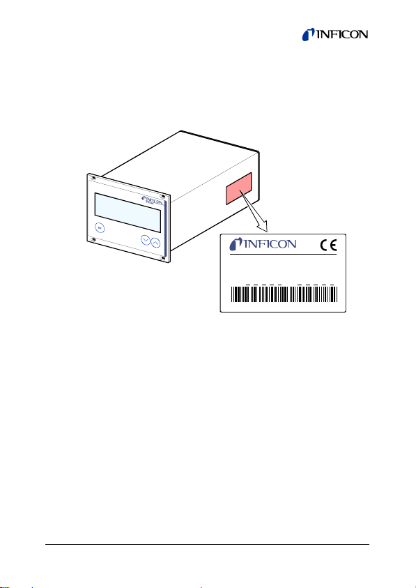
Product Identification
In all communications with INFICON, please specify the information on the product nameplate. For convenient reference copy
that information into the space provided below:
PGD400
100-240V 50/60Hz 30VA
P/N: S/N:
INFICON Instruments (Shanghai) Co.,Ltd.
Validity
This document applies to products with part number 398-800.
The part number (PN) can be taken from the product nameplate.
This document is based on firmware number F-1.01.
If your unit does not work as described in this document, please
check that it is equipped with the above firmware version
(→ 19).
We reserve the right to make technical changes without prior
notice.
All dimensions are indicated in mm.
2
Made in China
tinb14e1 (2009-07)
Page 3

Intended Use
The PGD400 is used together with an INFICON Pirani Standard
Gauge of the PSG5xx series for total pressure measurement. All
products must be operated in accordance with their respective
Operating Manuals.
Scope of Delivery
1× Pirani Gauge Display
1× Power cord
1× Operating Manual
tinb14e1 (2009-07) 3
Page 4

Contents
Product Identification 2
Validity 2
Intended Use 3
Scope of Delivery 3
1
Safety 6
1.1 Symbols Used 6
1.2 Personnel Qualifications 7
1.3 General Safety Instructions 7
1.4 Liability and Warranty 8
2 Technical Data 9
3 Installation 12
3.1 Installation in a Control Panel 12
3.2 Mains Power Connector 14
3.3 SENSOR Connector 15
3.4 OUTPUT Connector 16
4 Operation 18
4.1 Front Panel 18
4.2 Turning the PGD400 On and Off 19
4.3 Operating Modes 20
4.4 Measurement Mode 21
4.5 Parameter Mode 22
4.5.1 Parameters 24
5 Maintenance, Repair 26
6 Troubleshooting 27
7 Repair 29
8 Storage 29
9 Disposal 30
4
tinb14e1 (2009-07)
Page 5

Appendix 31
A: Default Parameters 31
B: Literature 31
EC Declaration of Conformity 32
For cross-references within this document, the symbol (→ XY)
is used, for cross-references to further documents, listed under
"Further Information", the symbol (→ [Z]).
tinb14e1 (2009-07) 5
Page 6
1 Safety
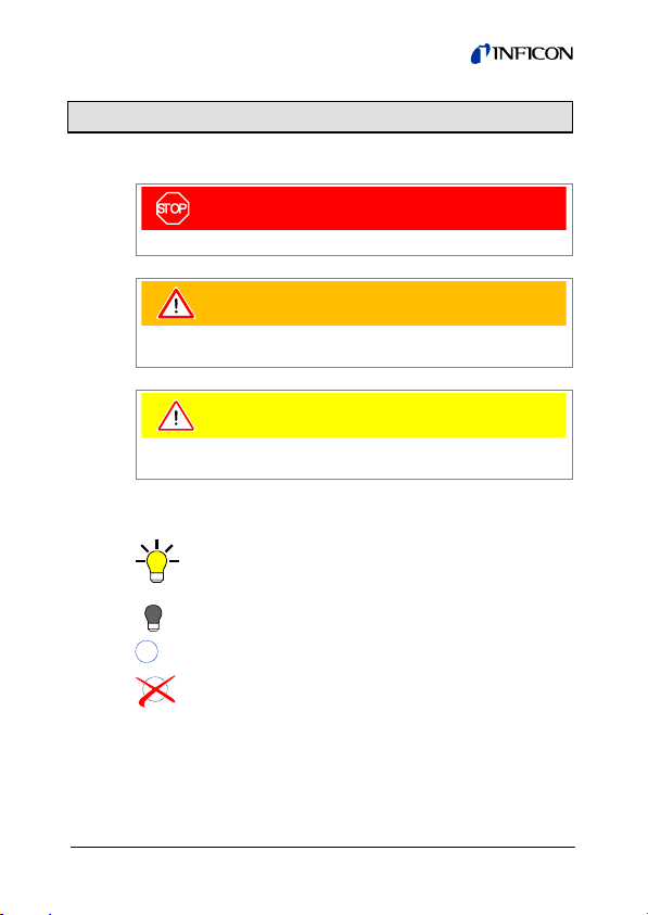
1.1 Symbols Used
DANGER
Information on preventing any kind of physical injury.
WARNING
Information on preventing extensive equipment and environmental damage.
Caution
Information on correct handling or use. Disregard can lead to
malfunctions or minor equipment damage.
Further symbols
The lamp/display is lit.
The lamp/display is dark.
set
Press the key (example: 'set' key).
Do not press any key
6
tinb14e1 (2009-07)
Page 7
1.2 Personnel Qualifications
Skilled personnel
All work described in this document may only be carried out by
persons who have suitable technical training and the necessary experience or who have been instructed by the end-user
of the product.
1.3 General Safety Instructions
Adhere to the applicable regulations and take the necessary
precautions for all work you are going to do and consider the
safety instructions in this document.
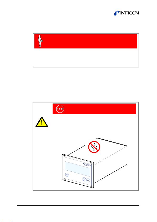
DANGER
DANGER: mains voltage
Contact with live parts is extremely hazardous
when any liquids penetrate into the unit.
Make sure no liquids penetrate into the equipment.
tinb14e1 (2009-07) 7
Page 8
Disconnecting device
The disconnecting device must be readily identifiable and easily
reached by the user.
To disconnect the controller from mains, you must unplug the
mains cable.
Disconnecting device
acc. to EN 61010-1
Communicate the safety instructions to all other users.
1.4 Liability and Warranty
INFICON assumes no liability and the warranty becomes null
and void if the end-user or third parties
• disregard the information in this document
• use the product in a non-conforming manner
• make any kind of interventions (modifications, alterations etc.)
on the product
• use the product with accessories not listed in the product
documentation.
8
tinb14e1 (2009-07)
Page 9

2 Technical Data
Mains specifications
Voltage 100 … 240 VAC
Frequency 50 … 60 Hz
Power consumption
Overvoltage category II
Protection class 1
Connection European appliance connector
Ambiance
Temperature
Storage
Operation
Relative humidity
Use indoors only
Pollution degree II
Degree of protection IP20 (EN 60529)
Compatible gauges
Number 1
Compatible types PSG500, PSG500-S,
Gauge connection
SENSOR connector RJ45 (FCC68), female
Operation
Front panel via 3 keys
≤30 VA
IEC 320 C14
–20 … +60 °C
+ 5 … +50 °C
≤80% up to +31 °C,
decreasing to 50% at +40 °C
max. altitude 2000 m NN
PSG502-S, PSG510-S,
PSG512-S
(pin assignment → 16)
tinb14e1 (2009-07) 9
Page 10

Measurement values
Measurement range
(air, O
, CO, N2)
2
Measurement error
Gain error
Offset error
-4
… 1000 mbar
5×10
(+1.9 … +10.0 VDC)
(→ [1])
≤0.02% FSr
≤0.05% FSr
Measurement rate 30 / s
Display rate 50 / s
Filter time constant 150 ms (f
Pressure units mbar, Pa, Torr
= 1 Hz)
g
Gauge supply
Voltage
+24 VDC ±5%
Current 750 mA
Power consumption 18 W
Fuse protection 900 mA with PTC element, self-
resetting after turning the
PGD400 off or disconnecting the
gauge
Switching function
Number 1
Reaction delay
≤10 ms if switching threshold
close to measurement value (for
larger differences consider filter
time constant).
-3
Adjustment range 1×10
Hysteresis
… 500 mbar
≥10% of measurement value
10
tinb14e1 (2009-07)
Page 11
Switching function relay
Contact type floating changeover contact
Load max. 60 VDC, 1 A (ohmic)
50 VAC, 5 A (ohmic)
Service life
Mechanic
Electric
Contact positions
8
cycles
10
5
cycles (at maximum load)
10
→ 17
OUTPUT connector 9-pole D-Sub, male
(pin assignment → 17)
Analog output
Number 1
Voltage range 0 … +10 V
Internal resistance
Measurement signal vs.
pressure
660 Ω
logarithmic, 1.286 V/decade
OUTPUT connector 9-pole D-Sub, male
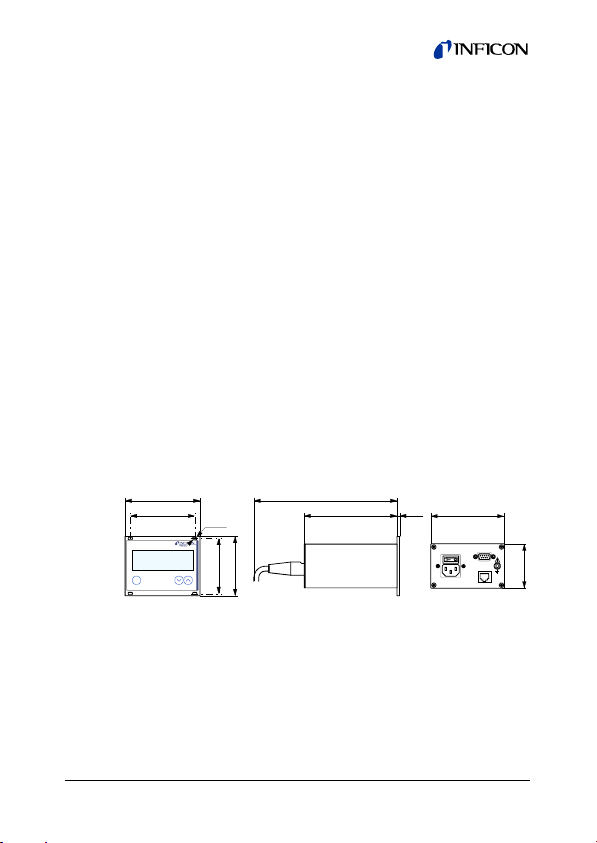
Dimensions [mm]
106.2
91.2
set
ø3
78
84
(pin assignment → 17)
212
131.5 3.5
104
OUTPUT
SENSOR
Use For incorporation into a control
panel
Weight 0.85 kg
62
tinb14e1 (2009-07) 11
Page 12

3 Installation
DANGER
DANGER: damaged product
Putting a damaged product into operation can be
extremely hazardous.
In case of visible damages, make sure the product
3.1 Installation in a Control Panel
The PGD400 is suited for incorporation into a control panel.
is not put into operation.
DANGER
DANGER: protection class of the control panel
If the product is installed in a rack, it is likely to
lower the protection class of the rack (protection
against foreign bodies and water) e.g. according to
the EN 60204-1 regulations for switching cabinets.
Take appropriate measures for the control panel to
meet the specifications of the protection class.
12
tinb14e1 (2009-07)
Page 13

For mounting the PGD400 into a control panel, the following cutout is required:
105
91.2
The admissible maximum
ambient temperature
→ 9) must not be
(
78
69
exceeded neither the air
circulation obstructed.
M3 or ø 3.5
For reducing the mechanical strain on the front panel, preferably
support the unit.
Slide the PGD400 into the cut-out of the control panel …
… and secure it with four M3 or equivalent screws.
tinb14e1 (2009-07) 13
Page 14

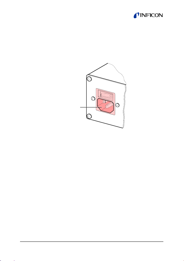
3.2 Mains Power Connector
DANGER
DANGER: line voltage
Incorrectly grounded products can be extremely
hazardous in the event of a fault.
Use only a 3-conductor power cable (3×1.5 mm
with protective ground. The power connector may
only be plugged into a socket with a protective
ground. The protection must not be nullified by an
extension cable without protective ground.
The unit is supplied with a 2 m power cord. If the mains cable is
not compatible with your system, use your own, suitable cable
with protective ground.
The socket must be fuseprotected with
10 A
max
Disconnecting device
acc. to EN 61010-1
If the unit is installed in a switch cabinet, the mains voltage
should be supplied and turned on via a central power distributor.
2
)
14
tinb14e1 (2009-07)
Page 15

Grounding
On the rear of the unit, there is a screw which can be used to
connect the unit to ground, e.g. using the grounding of the
pumping station.
Ground screw
3.3 SENSOR Connector
Connect the gauge to the SENSOR connector on the rear of the
unit. Use a screened 1:1 cable (electromagnetic compatibility).
Make sure the gauge is compatible (
DANGER
DANGER: protective low voltage
According to EN 61010, voltages exceeding
30 VAC or 60 VDC are hazardous.
tinb14e1 (2009-07) 15
Only connect a protective low voltage (SELV).
→ 9).
Page 16

Pin assignment SENSOR
Pin assignment of the
8-pole RJ45 appliance connector:
1
8
Pin Signal
4
Identification
1
Supply +24 VDC
2
Supply common GND
3
Signal input (Measurement signal+)
5
Signal common (Measurement signal–)
6
not connected
7
not connected
8
not connected
3.4 OUTPUT Connector
This connector allows to read the measurement signal and to
evaluate state of the floating switching function.
Connect the peripheral components to the OUTPUT
connector on the rear of the unit. Use a screened cable
(electromagnetic compatibility).
16
tinb14e1 (2009-07)
Page 17

DANGER
DANGER: protective low voltage
According to EN 61010, voltages exceeding
30 VAC or 60 VDC are hazardous.
Only connect a protective low voltage (SELV).
Pin assignment, Contact positions OUTPUT
Pin assignment of
5 1
the female 9-pole
D-Sub appliance
connector:
69
Pin Signal
1
Analog output 0 … +10 VDC
2
Chassis = GND
3
4
5
Pressure below
threshold
Pressure above
threshold or
power supply
turned off
9
not connected
8
not connected
not connected
6
not connected
7
tinb14e1 (2009-07) 17
Page 18

4 Operation
4.1 Front Panel
Measurement value in floating point or exponential
format or status messages
Warning/error
Switching function
status
Threshold
18
set
set
Operator keys
Pressure
unit
tinb14e1 (2009-07)
Page 19

4.2 Turning the PGD400 On and Off
Make sure the PGD400 is correctly installed and the specifications in the Technical Data are met.
Turning the PGD400 on
The power switch is on the rear of
the unit.
Turn the PGD400 on with the
power switch (or centrally, via a
switched power distributor, if the
unit is incorporated in a rack).
After power on, the PGD400 …
• automatically performs a self-test
• displays the firmware version F-1.01 for 3 s
• identifies if a gauge is connected
• activates the parameters that were in effect before the last
power off
• switches to the Measurement mode
Turning the PGD400 off
Turn the PGD400 off with the power switch (or centrally, via a
switched power distributor, if the unit is incorporated in a rack).
Wait at least 10 s before turning the PGD400 on again in
order for it to correctly initialize itself.
tinb14e1 (2009-07) 19
Page 20

4.3 Operating Modes
The PGD400 works in the following operating modes:
• Measurement mode
for displaying measurement values or status messages
→ 21)
(
• Parameter mode
for entering or displaying parameters (
→ 22)
20
tinb14e1 (2009-07)
Page 21

4.4 Measurement Mode
The Measurement mode is the standard operating mode of the
PGD400. Measurement values as well as status messages
(→ 27) are displayed in this mode.
Measurement mode
Measurement value
Status
>5 s
Power on
Parameter
mode
Pressure p
range
Measurement
tinb14e1 (2009-07) 21
Page 22

Getting to the Parameter mode
→ 22
4.5 Parameter Mode
The Parameter mode is used for displaying, editing and entering
parameter values.
Measurement
mode
Power on
>5 s
Parameter mode
Unit
Threshold
22
tinb14e1 (2009-07)
Page 23

Selecting a parameter
Ö The name of the parameter
Editing the parameter value
Ö Press key <1 s:
Ö Save the modificated parameter
e.g.:
Unit
is displayed as long as the key is
pressed or at least for 1 s.
Afterwards, the currently valid parameter value is displayed.
The value is increased / decreased
by 1 increment.
Press key >1 s:
The value is increased / decreased continuously.
value.
tinb14e1 (2009-07) 23
Page 24

4.5.1 Parameters
Switching threshold
The PGD400 has a switching function with one adjustable
threshold. The status of the switching function is displayed on
the front panel (
contact at the CONTROL connector (
Pressure pDisplay
→ 18) and can be evaluated via the floating
→ 16).
e
M
e
u
l
a
v
t
n
e
m
e
r
u
s
a
Hysteresis (10%
of threshold value)
Time t
24
4
3
2
function
Off On
Switching
e.g.:
4
3
2
4
3
2
Off
Value
The switching threshold defines the
pressure at which the switching function is activated when the pressure is
dropping.
(default)
tinb14e1 (2009-07)
Page 25

Pressure unit
Unit of measured values, thresholds etc.
Value
Ö mbar (default)
Ö Torr
Ö Pascal
tinb14e1 (2009-07) 25
Page 26

5 Maintenance, Repair
The product requires no maintenance.
Cleaning the PGD400
For cleaning the outside of the PGD400, a slightly moist cloth will
usually do. Do not use any aggressive or scouring cleaning
agents.
DANGER
DANGER: mains voltage
Contact with live parts is extremely hazardous
when any liquids penetrate into the unit.
Make sure no liquids penetrate into the equipment.
26
tinb14e1 (2009-07)
Page 27

6 Troubleshooting
Signalization of errors
Error messages
Possible cause and remedy / acknowledge-
ment
Interruption or instability in sensor line or
connector (Sensor error).
Possible cause and remedy / acknowledge-
ment
Pirani error (sensor defective).
Status messages
Ö Replace the sensor
Possible cause and remedy / acknowledge-
ment
0.5 V < measurement signal < 1.5 V
Ö Adjust the gauge (→ [1]).
10.3 V < measurement signal < 13.7 V
Ö Adjust the gauge (→ [1]).
tinb14e1 (2009-07) 27
Page 28

Technical support
If the problem persists after the message has been ack-
nowledged for several times and/or the gauge has been
exchanged, please contact your local INFICON service
center.
28
tinb14e1 (2009-07)
Page 29

7 Repair
Please contact your local INFICON service center.
INFICON assumes no liability and the warranty becomes null
and void if repair work is carried out by the end-user or third
parties.
8 Storage
Caution
Caution: electronic component
Inappropriate storage (static electricity, humidity
etc.) can damage electronic components.
Store the product in a bag or container. Observe
the corresponding specifications in the technical
data (
→ 9).
tinb14e1 (2009-07) 29
Page 30

9 Disposal
DANGER
DANGER: contaminated parts
Contaminated parts can be detrimental to health
and environment.
Before beginning to work, find out whether any
parts are contaminated. Adhere to the relevant
regulations and take the necessary precautions
N
Separating the components
After disassembling the product, separate its components according to the following criteria:
• Contaminated components
• Other components
30
when handling contaminated parts.
WARNING
WARNING: substances detrimental to the environment
Products or parts thereof (mechanical and electric
components, operating fluids etc.) can be detrimental to the environment.
Dispose of such substances in accordance with the
relevant local regulations.
Contaminated components (radioactive, toxic, caustic or biological hazard etc.) must be decontaminated in accordance
with the relevant national regulations, separated according to
their materials, and disposed of.
Such components must be separated according to their materials and recycled.
tinb14e1 (2009-07)
Page 31

Appendix
A: Default Parameters
Default User
-3
1.0
mbar
mbar
B: Literature
[1] www.inficon.com
Operating Manual
Pirani Standard Gauge
PSG500, PSG500-S, PSG502-S,
PSG510-S, PSG512-S
tina44e1
INFICON AG, LI–9496 Balzers, Liechtenstein
tinb14e1 (2009-07) 31
Page 32

EC Declaration of Conformity
We, INFICON, hereby declare that the equipment mentioned
below complies with the provisions of the Directive relating to
electrical equipment designed for use within certain voltage limits
2006/95/EC and the Directive relating to electromagnetic compatibility 2004/108/EC.
Pirani Gauge Display
PGD400
Standards
Harmonized and international/national standards and specifications:
• EN 61010-1:2001
measurement, control and laboratory use)
• EN 61326-1:2006
and laboratory use; general EMC requirements)
• EN 61326-2-2:2006
control and laboratory use; particular EMC requirements)
Signatures
INFICON AG, Balzers
6 July 2009 6 July 2009
(Safety requirements for electrical equipment for
(Electrical equipment for measurement, control
(Electrical equipment for measurement,
32
Dr. Urs Wälchli
Managing Director
Markus Truniger
Product Manager
tinb14e1 (2009-07)
Page 33

Notes
tinb14e1 (2009-07) 33
Page 34

Notes
34
tinb14e1 (2009-07)
Page 35

Notes
tinb14e1 (2009-07) 35
Page 36

LI–9496 Balzers
Liechtenstein
Tel +423 / 388 3111
Fax +423 / 388 3700
Original: English tinb14e1 (2009-07) reachus@inficon.com
t i nb14e1
www.inficon.com
 Loading...