

Page 1

tina14e1
Penning Gauge
OPERATING MANUAL
PEG100
Part Number
351-000
351-002
Page 2

General Remarks
We reserve the right to alter the design or any data given
in these Operating Instructions.
The illustrations are not binding.
Contents Page
1 Description . . . . . . . . . . . . . . . . . . . . . . . . . . 3
1.1 General . . . . . . . . . . . . . . . . . . . . . . . . . . . . . 3
1.1.1 Purpose . . . . . . . . . . . . . . . . . . . . . . . . . . . . . 4
1.2 Technical Data . . . . . . . . . . . . . . . . . . . . . . . . 4
1.2.1 General Data . . . . . . . . . . . . . . . . . . . . . . . . . 4
1.2.2 Measurement System . . . . . . . . . . . . . . . . . . . 5
1.2.3 Signal Output . . . . . . . . . . . . . . . . . . . . . . . . . 5
1.2.4 Control Inputs . . . . . . . . . . . . . . . . . . . . . . . . . 5
1.2.5 Status Output . . . . . . . . . . . . . . . . . . . . . . . . . 5
1.2.6 Mechanical Data . . . . . . . . . . . . . . . . . . . . . . . 6
1.2.7 Ambient Conditions . . . . . . . . . . . . . . . . . . . . . 6
1.3 Technical Description . . . . . . . . . . . . . . . . . . . 6
1.4 Equipment . . . . . . . . . . . . . . . . . . . . . . . . . . . 7
1.4.1 Supplied Equipment . . . . . . . . . . . . . . . . . . . . 7
1.4.2 Accessories . . . . . . . . . . . . . . . . . . . . . . . . . . 7
2 Operation . . . . . . . . . . . . . . . . . . . . . . . . . . . 7
2.1 Installation . . . . . . . . . . . . . . . . . . . . . . . . . . . 7
2.2 Electrical Connection . . . . . . . . . . . . . . . . . . . 9
2.2.1 Power Supply . . . . . . . . . . . . . . . . . . . . . . . . 11
2.2.2 Switching on the High Tension . . . . . . . . . . . . 11
Page
2.2.3 Measurement Signal Output . . . . . . . . . . . . . 11
2.2.4 Status Output . . . . . . . . . . . . . . . . . . . . . . . . 12
2.2.5 Identification . . . . . . . . . . . . . . . . . . . . . . . . . 12
2.3 Start-up . . . . . . . . . . . . . . . . . . . . . . . . . . . . 13
2.3.1 Operation . . . . . . . . . . . . . . . . . . . . . . . . . . . 13
2.3.2 Measurement System Status Indication . . . . . 14
2.3.3 Degassing . . . . . . . . . . . . . . . . . . . . . . . . . . 14
2.4 Troubleshooting . . . . . . . . . . . . . . . . . . . . . . 15
3 Maintenance . . . . . . . . . . . . . . . . . . . . . . . . 16
3.1 Service at INFICON . . . . . . . . . . . . . . . . . . . 16
3.2 The Electronics Assembly . . . . . . . . . . . . . . . 16
3.3 Cleaning the Sensor . . . . . . . . . . . . . . . . . . . 16
3.3.1 Detaching the Electronics Assembly . . . . . . . 16
3.3.2 Disassembly of the Sensor . . . . . . . . . . . . . . 17
3.3.3 Cleaning the Individual Parts . . . . . . . . . . . . . 17
3.3.4 Assembly of the Sensor . . . . . . . . . . . . . . . . 18
3.3.5 Assembly of the Electronics Assembly . . . . . . 18
4 Spare Parts List . . . . . . . . . . . . . . . . . . . . . 18
5 Disposal . . . . . . . . . . . . . . . . . . . . . . . . . . . 19
Annex 1 . . . . . . . . . . . . . . . . . . . . . . . . . . . . . . . . . 20
Annex 2 . . . . . . . . . . . . . . . . . . . . . . . . . . . . . . . . . 22
EEC Declaration of Conformity . . . . . . . . . . . . . . . . 24
Declaration of Contamination . . . . . . . . . . . . . . . . . 25
2
tina14e1 (0106) PEG100.ga
Page 3

1 Description
1.1 General
The PEG100 Penning Gauge is supplied ready for operation. Even so, we recommend to read these Operating
Instructions with care so as to ensure optimum operating
conditions right from the start.
These Operating Instructions contain important information on the functions, installation, start-up, operation and
troubleshooting of the PEG100.
Important remarks concerning operational safety and
protection are emphazised as follows:
Warning Indicates procedures that must be strict-
ly observed to prevent hazards to persons.
Caution Indicates procedures that must strictly
be observed to prevent damage to, or
destruction.
Note
Indicates special technical requirements that the user
must comply with.
The references to diagrams, e.g. (4/1), consist of the Fig.
No. and the item No. in that order.
Unpack the PEG100 immediately after delivery, even if it
is to be installed at a later date.
Examine the packaging for any external damage. Completely remove all packaging materials.
Note
Retain the shipping container and the packaging materials in the event of complaints about damage.
Check that the PEG100 is complete (see Section 1.4).
Carefully examine the PEG100 visually.
If any damage is discovered, report it immediately to the
forwarding agent and insurer. If the damaged part has to
be replaced, please get in touch with the orders department.
3
tina14e1 (0106) PEG100.ga
Page 4

1.1.1 Purpose
The PEG100 Penning Gauge is a compact active pressure converter housing a measurement system as well
as the corresponding operating electronics. It has been
developed specifically for integration into vacuum
systems and offers a measurement range from 1·10-9to
1·10-2mbar.
The PEG100 is connected directly to the vacuum system through its DN 25 KF or DN 40 CF flange.
The electrical connection is provided through a screened
8-way FCC 68 connector.
Moreover, the technical data as published in Section 1.2
must be observed.
1.2 Technical Data
1.2.1 General Data
Measurement range 1·10-9to 1·10-2mbar/Torr
Measurement uncertainty in the range
from 1·10-8to 1·10-4mbar:
Deviation from the characteristic
± 30 % of the displayed value
Average temperature coefficient of the output span
< 0.5 % / K of the displayed value
Reproducibility < 4 % of the displayed value
Measurement principle
Cold cathode ionization according to Penning
Supply voltage 14.5 to 36 V DC, typ. 24 V DC
Ripple ≤ 2 V
pp
Power consumption < 2 W
Protection IP 40
Electromagnetic compatibility (EMI) CE mark
interference tolerance to EN 50082-2, Tab. 1, 2, 3
interference emission levels to EN 50081-1 and
FCC Rules Part 15, Class B
Flammability UL 94 - V2
4
tina14e1 (0106) PEG100.ga
Page 5

Status displays
Operation (POWER) orange LED
Ready to measure (ignited) READY green LED
1.2.2 Measurement System
Measurement system detachable Vacuum connection DN 25 KF or DN 40 CF Degassing temperature see Section 2.3.3
Dead volume 21 cm3approx.
Materials in contact with the medium
stainless steel, CrNi,
Al2O3ceramics, NiFe, Ni, Ti
Overpressure tolerance ≤ 10 bar abs.
(The limits for the flange connections must be observed)
Operating voltage 1.6 kV (current limited to < 0.5 mA)
Ignition voltage 2.8 kV (current limited to < 0.5 mA)
1.2.3 Signal Output
Signal output 0 to 10.6 V Permissible load resistance Ra≥ 10 kΩ
Measurement signal 0.66 V to 10 V;
logarithmic, 1.333 V per decade
Status signal (not ignited) 0.4 V
1.2.4 Control Inputs
Input resistance RE: 10 kΩ approx.
High voltage cut-in with negative logic at Pin 7:
High voltage ON at U < 2.5 V
High voltage OFF at U > 4 V
or
High voltage cut-in with positive
logic at Pin 8:
High voltage ON at U > 12 V
High voltage OFF at U < 7 V
(for this also refer to Fig. 3 and Section 2.2.2).
1.2.5 Status Output
Ready to measure High level (13.5-35 V, max. 50 mA)
Error (not ignited, HV off) 0V
For this refer also to Section 2.2.4.
5
tina14e1 (0106) PEG100.ga
Page 6

1.2.6 Mechanical Data
Dimensions (WxHxD) 80 x 126 x 73 mm
Weight 500 g approx.
1.2.7 Ambient Conditions
Storage temperature range -20 °C to +70 °C
Climatic rating KWF to DIN 400 40
Operating temperature range 10 °C to 50 °C
Max. rel. humidity of the ambient air (on 30
days per year, non-condensing) 70 %1)or 95 %
1)
usable measurement range 10-2to 10-7mbar
2)
usable measurement range 10-2to 10-9mbar
1.3 Technical Description
Based on a supply voltage of 24 V the PEG100 Penning
Gauge generates the internal supply voltages required
for operation of the integrated measurement system.
The PEG100 supplies a logarithmic representation of the
vacuum pressure by way of a voltage signal which ranges from 0.66 V to 10 V. Moreover, the high tension
generated in the PEG100 can be switched on and off by
applying an external control voltage or by connecting an
external switch.
When the gas discharge in the measurement system is
ignited, the operating voltage is raised to 2.8 kV. After
2)
successful ignition, this voltage then drops to 1.6 kV thereby increasing the useful service life of the measurement system.
Astatus output indicates the two possible conditions of
the measurement system:
1.not ignited (including high tension OFF) and
2.ignited (and pressure > 3·10-9mbar).
Amuch improved ignition characteristic in the high vacu-
um range has been obtained through the special design
for the electrodes in the measurement system.
6
tina14e1 (0106) PEG100.ga
Page 7

1.4 Equipment
1.4.1 Supplied Equipment
PEG100, DN 25 KF Part No. 351-000
PEG100, DN 40 CF Part No. 351-002
Replacement cathode plate of titanium --
Replacement ceramics disc --
3.5 mm jack plug -Operating Instructions tina14e1
1.4.2 Accessories
Part No.
Replacement kit 351-490
consisting of:
Cathode plate of titanium (5 pcs.)
Ceramics disc (5 pcs)
Gauge
2 Operation
2.1 Installation
The PEG100 Penning Gauges should preferably be
mounted flange down. Inclined installation is possible but
the horizontal orientation must not be exceeded.
Flange up installation is not permissible because under
such circumstances condensate may collect in the
PEG100. This will either adversely affect the measurements, or the sensor itself may possibly be damaged.
The PEG100 is equipped with a DN 25 KF or a DN 40
CF connection flange which is used to connect the
PEG100 to the mating connection flange on a vacuum
system with the aid of a centering ring and a clamping
ring.
The cathode plate (5/5) also acts as a baffle.
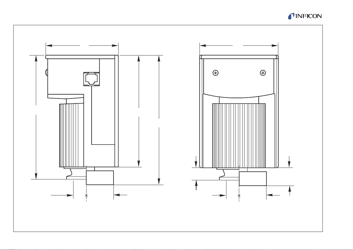
For the dimensional drawing, see Fig. 1.
7
tina14e1 (0106) PEG100.ga
Page 8
8
tina14e1 (0106) PEG100.ga
DN 25 KF
143,5
114
73
POWER READY
25
80
DN 40 CF
130,5
12
DN 40 CF
DN 25 KF
Fig. 1 Dimensional drawing for PEG100
Page 9

9
tina14e1 (0106) PEG100.ga
2.2 Electrical Connection
The supply voltage and the high voltage switching signal
as well as the measurement voltage signal are carried
through the 8-way FCC 68 socket.
The pinout is given in Fig. 2.
Pin Signal Designation
on the rear
————————————————————————
Pin 1 Supply voltage
14.5 V to 36 V DC + 24 V DC
Pin 2 0 V supply; used as the ground
reference for the supply and
control signal voltages. COMMON
Pin 3 Pressure dependant logarithmic
signal output SIGN 0 - 10 V
Pin 4 „PEG100“ identification
code (100 kΩ) IDENT
Pin 5 Signal ground
(use only for the
pressure signal) SIGN COM
Pin 6 Status (ready to measure) STATUS
Pin 7 High tension „ON / OFF“
(control input); Low active HV ON (L)
Pin 8 High tension „ON / OFF“
(control input); High active HV ON (H)
Note
Signal ground (Pin 5) and power supply ground (Pin 2)
are internally linked. For this also refer to the block diagram of Fig. 3.
Two examples of how to connect the PEG100 are given
in Annex 2.
Fig. 2 Connection socket
Pin 1
Page 10

10
tina14e1 (0106) PEG100.ga
3
7
6
8
5
1
4
2
LED
"POWER"
LED
"READY"
R
v
7,48 M
Ω
+ 10,5 V
Ω
100 k
2,8 kV
1,6 kV
Fig. 3 Block diagram PEG100
Characteristic
adaptation
Ingnition
monitor
HV ON (L)
Status
High tension switchover
Measurement
system
Signal output
Power supply ground
Signal ground
Power supply
Identification
HV ON (H)
Page 11

11
tina14e1 (0106) PEG100.ga
2.2.1 Power Supply
Warning
The PEG100 may only be connected to
supply units or measuring instruments
which meet the requirements of mains
isolated extra-low voltages (PELV) and
VDE 0100.
The PEG100 is capable of operating off supply voltages
ranging from 14.5 V to 36 V. Asupply voltage of 24 V DC
is recommended.
The power supply must be connected to Pin 1 (+) and
Pin 2 (power supply ground).
2.2.2 Switching on the High Tension
The high voltage may be switched on either through Pin
7 using negative logic or Pin 8 using positive logic.
In each case Pin 2 must be used as the reference potential.
Pin 7 switches the high voltage on when
- contact is established with Pin 2 or
- a voltage of less than 2.5 V is present with reference to
Pin 2.
Pin 7 switches the high voltage off when
- there is no contact with Pin 2 (open input) or
- a voltage greater than 4 V is present with reference to
Pin 2.
Pin 8 switches the high voltage on when
- contact is established with Pin 1 (supply voltage) or
- a voltage greater than 12 V is present with reference to
Pin 2.
Pin 8 switches the high voltage off when
- there is no contact with Pin 1 (open input) or
- a voltage of less than 7 V is present with reference to
Pin 2.
Operation of the PEG100 in the pressure range above
10-2mbar will cause the accumulation of contaminations
and will thus reduce service life. For this reason, the high
tension should only be switched on or off when the pressure has dropped to the 10-2to 10-3mbar range.
The high tension may also be switched on or off directly
by the output signal provided by a Pirani Standard
Gauge (PSG) with switching point. Thus the PEG100
can be switched on or off automatically at a pressure of
approximately 5·10-3mbar.
2.2.3 Measurement Signal Output
The PEG100 supplies a defined output signal ranging
from 0.66 V to 10 V at Pin 3 with reference to Pin 5 which
is signal ground. For this also refer to Table 1 in Annex
Page 12

1. Table 1 has been included to clarify the relationship
between the output voltage and the pressure.
Note
The measurement signal provided by the PEG100
depends on the type of gas. The values stated in Table 1
apply to nitrogen and air. For other gases, corresponding
correction factors must be used which are available from
INFICON upon request.
2.2.4 Status Output
When the gauge is ready to measure, this is indicated
via the status output.
Status Status signal at Pin 6
(with respect to Pin 2)
————————————————————————
High voltage OFF 0 V
High voltage ON 0 V
(not yet ignited)
High voltage ON 0 V
at p < 3·10-9mbar
High voltage ON High (13.5 - 32 V, depending
at p > 3·10-9mbar on the supply voltage
(50 mA max.)
Note
When the pressure drops below 3·10-9mbar, the status
signal remains HIGH.
Caution FET output: The max. voltage is 42 V DC.
The max. load current is 100 mA DC.
Voltage output: Load current is 50 mAmax.
When exceeding these maximum ratings
the PEG100 itself and/or any connected
equipment may be damaged.
When the PEG100 is ready to make measurements, the
FET is conductive. For this also refer to Section 2.3.2.
2.2.5 Identification
For the purpose of identifying the connected type of
gauge and the pressure range, the PEG100 is equipped
with an identification resistor (R = 100 kΩ) between Pin
4 and Pin 2. This resistor may be sensed by connected
operating or control units so that these can automatically adapt.
12
tina14e1 (0106) PEG100.ga
Page 13

13
tina14e1 (0106) PEG100.ga
2.3 Start-up
Connect the PEG100 according to Section 2.1 and 2.2.
Warning A high tension which is dangerous when
touched is applied to the sensor in the
PEG100.
You must always switch off the supply
voltage for the PEG100 before starting
any work on the PEG100 (even when
removing the PEG100 from the connection flange) so as to avoid injury when
inadvertently coming in to contact with
the high tension.
2.3.1 Operation
Apply the 24 V supply voltage to the PEG100.
The orange „POWER“ LED (4/1) comes on.
Switch the high tension on via the high tension switching
input. See Section 2.2.2.
After successful ignition and at a pressure > 3·10-9mbar
the additional green or READY LED (4/2) will come on.
Now the PEG100 is ready to make measurements.
Fig. 4 PEG100 - front view
1
2
POWER
READY
Key to Fig. 4
1 „POWER“ LED (orange)
2 „READY“ LED (green)
Page 14

No LED on.
- Supply voltage is missing.
→ Measurement signal: 0 V
Only the orange LED (4/1) is on.
- The supply voltage is present.
- The high tension has not been switched on.
→ Measurement signal: 0 V
The green LED (4/2) is on, the orange LED (4/1) is on.
- The supply voltage is present.
- The high tension has been switched on.
- The gas discharge has been started.
- The pressure is over 3·10-9mbar.
→ Measurement signal: > 0.66 V
2.3.2 Measurement System Status Indication
In the case of the Penning method of measurement one
only may draw conclusions as to proper functioning
while the PEG100 is in the measurement mode, i.e.
when the gas discharge is running.
Trouble-free operation („READY“ LED (4/2) is on, status
output HIGH) is marked by the presence of a pressure
dependant signal starting at a pressure of about 3·10
-9
mbar up to the range limit of 1·10-2mbar. When the pressure drops < 3·10-9mbar this status is also maintained.
14
tina14e1 (0106) PEG100.ga
When the “READY” LED (4/2) is not on, status output 0
V:
Cause 1: When the high voltage was switcthed on the
pressure was below 3·10-9mbar.
Cause 2: No ignition of the gas discharge, even if the
power supply voltage is present, the high tension has been switched on and a pressure
between about 3·10-9mbar and 1·10-2mbar.
2.3.3 Degassing
Caution
Before baking out the sensing cell you
must detach the electronics assembly
from the sensing cell. The electronics
assembly may be damaged when exceeding a temperature of 70 °C.
Caution Before baking out, you must make sure
that an ultra sealing disc (PEG100, DN
25 KF) or a copper seal (PEG100, DN
40 CF) is used as the flange seal.
The PEG100 are equipped with all-metal sensing cells
so that any outgassing caused by polymer seals is entirely avoided.
After having detached the electronics (refer to Section 3.3.1) from the sensing cell, the outgassing rate of
the sensing cell may be reduced considerably by baking
Page 15

out, so that the accuracy of the measurements in the
range below 1·10-6mbar is improved.
Note
When using the PEG100 chiefly in the UHV range
(< 10-8mbar) it is recommended to remove the cathode
plate. This helps to the reduce the surface area of the
surfaces which may release gas.
How to proceed in order to detach the electronics assembly is described in Section 3.3 (cleaning of the sensor).
Permissible bake out temperatures:
Sensing cell of the PEG100, DN 25 KF:
200 °C
(with ultra sealing disc)
Sensing cell of the PEG100, DN 40 CF: 350 °C
2.4 Troubleshooting
No LED is on.
Possible cause: Supply voltage is missing.
The „POWER“ LED (4/1) is on, the „READY“ LED
(4/2) is not on.
Possible cause:
• High tension has not been activated.
• Pressure has dropped below 3·10
-9
mbar.
• The gas discharge has not ignited.
• Sensing cell not properly connected to the
electronics assembly (e.g. after maintenance).
• Missing anode ring (e.g. after maintenance).
The measurement signal is always greater than 10 V
even if the pressure is much lower than 10-2mbar.
Possible cause: Short circuit in the sensing cell.
Remedy: Clean the sensing cell. For this refer
to Section 3.3.
During pumpdown the measurement signal remains
at some level although the pressure is dropping.
Possible cause: Contamination within the
sensing cell.
Remedy: Replace the sensing cell.
15
tina14e1 (0106) PEG100.ga
Page 16

3 Maintenance
3.1 Service at INFICON
Warning Contaminated products (e.g. radioac-
tive, toxic, caustic or microbiological
hazard) can be detrimental to health and
environment.
Products returned to Inficon should preferably be free of
harmful substances. Adhere to the forwarding regulations of all involved countries and forwarding companies
and enclose a duly completed declaration of contamination (see Annex).
Products that are not clearly declared as „free of harmful substances“ are decontaminated at the expense of
the customer.
Products not accompanied by a duly completed declaration of contamination are returned to the sender at his
own expense.
3.2 The Electronics Assembly
The electronics assembly of the PEG100 does not require any maintenance.
16
tina14e1 (0106) PEG100.ga
3.3 Cleaning the Sensor
Warning A high tension which is dangerous when
touched is applied to the sensor in the
PEG100.
You must always switch off the supply
voltage for the PEG100 before starting
any work on the PEG100 (even when
removing the PEG100 from the connection flange) so as to avoid injury when
inadvertently coming in to contact with
the high tension.
3.3.1 Detaching the Electronics Assembly
In order to detach the electronics assembly and the
magnet assembly (5/1) you must loosen the two cross
head screws which can be accessed through two holes
in the rear of the PEG100 by turning these by about 1.5
turns.
Then the electronics assembly and the magnet assembly (5/1) may be pulled off from the sensor housing.
Caution The magnet assembly (5/1) may drop
down during the pulling off process.
Page 17

3.3.2 Disassembly of the Sensor
The sensor consists of the housing, the anode ring (5/4)
with ignition aid (5/2) and the cathode plate (5/5). See
Fig. 7.
How to disassemble:
1) Use a pair of tweezers to pull the cathode plate (5/5)
out of the sensor.
2) Use a pair of pliers to pull the anode ring out from the
housing; for this move the pliers to and fro a little.
3) Detach the ceramics disc (5/3) from the current feedthrough.
3.3.3 Cleaning the Individual Parts
Caution
Do not damage the sealing surfaces of
the vacuum flange!
In the case of severe contamination, the inside of the
housing may be cleaned with steel wool or similar and
then subjected to further cleaning with alcohol. Finally
blow clean with oil-free pressurized air or nitrogen. Any
possibly present flakes will be removed by blowing these
out of the housing.
If possible, the cathode plate (5/5) should be replaced by
a new cathode plate. The same should be done for the
anode ring (5/4) with the ignition aid (5/2) and the cera-
17
tina14e1 (0106) PEG100.ga
Fig. 5 Sensor
6
2
5
3
4
1
1
Key to Fig. 5
1 Magnet assembly
2 Ignition aid
3 Ceramics disc
4 Anode ring
5 Cathode plate
6 Sensor housing with flange
Page 18

mics protection disc (5/3) which protects the current
feed-through against contamination.
3.3.4 Assembly of the Sensor
The sensor is reassembled in the reverse order as for
disassembly which is described in Section 3.3.2.
When inserting the anode ring (5/4) you must make sure
that a clearance of 1 mm remains between the wings of
the ignition aid (5/2) and the wall of the housing. Moreover, make sure that the anode ring is lying snug on the
ceramics disc.
When inserting the cathode plate (5/5) into the housing
the wings of the ignition aid (5/2) must not be bent.
Therefore insert slowly and carefully.
3.3.5 Assembly of the Electronics Assembly
How to proceed:
1) Place the magnet assembly on the sensor.
2) Push the electronics assembly over the magnet
assembly and the sensor, and turn slightly as required until the correct orientation between electronics
assembly and sensor has been found. When the
electronics assembly has been placed as required,
the black magnet housing is fully surrounded by the
housing of the PEG100.
3) Retighten the cross head screws at the rear of the
PEG100.
4 Spare Parts List
Part No.
Replacement kit 351-490
consisting of:
Cathode plate of titanium (5 pcs.)
Ceramics disc (5 pcs)
Gauge
Sensor (DN 25 KF)
complete with magnet assy. (PR 25) 399-510
18
tina14e1 (0106) PEG100.ga
Page 19

5 Disposal
Warning Contaminated parts
Contaminated parts can be detrimental
to health and environment.
Before beginning to work, find out whether any parts are
contaminated. Adhere to the relevant regulations and
take the necessary precautions when handling contaminated parts.
Warning Substance detrimental to the environ-
ment
Products or parts thereof (mechanical
and electric components, operating
fluids etc.) can be detrimental to the
environment.
Dispose of such substance in accordance with the relevant local regulations.
Separating the components
After disassembling the product, separate its components according to the following criteria:
Contaminated components
Contaminated components (radioactive, toxic, caustic
or biological hazard etc.) must be decontaminated in
accordance with the relevant national regulations,
separated according to their materials, and disposed
of.
Other components
Such components must be separated according to
their materials and recycled.
19
tina14e1 (0106) PEG100.ga
Page 20

Annex 1
Table 1 Relationship between output voltage and pressure (U = 0.4 V; “not ignited”)
U (Out) Pressure
[V] [mbar]
0.667 1.00E-09
0.8 1.26E-09
1 1.78E-09
1.1 2.11E-09
1.2 2.51E-09
1.3 2.99E-09
1.4 3.55E-09
1.5 4.22E-09
1.6 5.01E-09
1.7 5.96E-09
1.8 7.08E-09
1.9 8.41E-09
2 1.00E-08
2.1 1.19E-08
2.2 1.41E-08
2.3 1.68E-08
2.4 2.00E-08
2.5 2.37E-08
2.6 2.82E-08
2.7 3.35E-08
2.8 3.98E-08
2.9 4.73E-08
3 5.62E-08
3.1 6.68E-08
20
tina14e1 (0106) PEG100.ga
U (Out) Pressure
[V] [mbar]
5.6 5.01E-06
5.7 5.96E-06
5.8 7.08E-06
5.9 8.41E-06
6 1.00E-05
6.1 1.19E-05
6.2 1.41E-05
6.3 1.68E-05
6.4 2.00E-05
6.5 2.37E-05
6.6 2.82E-05
6.7 3.35E-05
6.8 3.98E-05
6.9 4.73E-05
7 5.62E-05
7.1 6.68E-05
7.2 7.94E-05
7.3 9.44E-05
7.4 1.12E-04
7.5 1.33E-04
7.6 1.59E-04
7.7 1.88E-04
7.8 2.24E-04
7.9 2.66E-04
U (Out) Pressure
[V] [mbar]
3.2 7.94E-08
3.3 9.44E-08
3.4 1.12E-07
3.5 1.33E-07
3.6 1.59E-07
3.7 1.88E-07
3.8 2.24E-07
3.9 2.66E-07
4 3.16E-07
4.1 3.76E-07
4.2 4.47E-07
4.3 5.31E-07
4.4 6.31E-07
4.5 7.50E-07
4.6 8.91E-07
4.7 1.06E-06
4.8 1.26E-06
4.9 1.50E-06
5 1.78E-06
5.1 2.11E-06
5.2 2.51E-06
5.3 2.99E-06
5.4 3.55E-06
5.5 4.22E-06
U (Out) Pressure
[V] [mbar]
8 3.16E-04
8.1 3.76E-04
8.2 4.47E-04
8.3 5.31E-04
8.4 6.31E-04
8.5 7.50E-04
8.6 8.91E-04
8.7 1.06E-03
8.8 1.26E-03
8.9 1.50E-03
9 1.78E-03
9.1 2.11E-03
9.2 2.51E-03
9.3 2.99E-03
9.4 3.55E-03
9.5 4.22E-03
9.6 5.01E-03
9.7 5.96E-03
9.8 7.08E-03
9.9 8.41E-03
10 1.00E-02
Page 21

tina14e1 (0106) PEG100.ga
21
Characteristic PEG100
Equation:
U(a) = [1.33·lg (p / mbar) + 12.66] Volt
Pressure p / mbar
Output voltage U(a) / Volt
Page 22

tina14e1 (0106) PEG100.ga
22
Annex 2
PTR 225
1
0...10 V
3
5
2
6
7
14,5 ... 36 V
GND
+
8
Example for connecting the PEG100: Switching the high tension via an external switch or contact
Measurement
signal
Status message
HV ON (L)
HV ON (H)
HV-ON
switch
HV-ON
switch
Relay, for
example
PEG100
Page 23

tina14e1 (0106) PEG100.ga
23
1
Example for connecting the PEG100: Switching the high tension automatically through a Pirani Standard Gauge with switching point
Measurement
signal
Status message
Relay, for
example
HV ON (L)
PEG100
Pirani Standard
Gauge
3
5
2
1
3
5
6
7
2
0...10 V
0...10 V
14,5 ... 36 V
+
GND
Page 24

tina14e1 (0106) PEG100.ga
24
EEC Declaration of Conformity
as defined by the Directive relating to machinery
98/37/EG, Appendix IIb.
We -INFICON - herewith declare that the products defined
below meet the basic requirements regarding safety and
health of the relevant EEC directives by design, type and
the versions which are brought in to circulation by us.
We also declare that the equipment mentioned below
complies with the provisions of the Directive relating to
electrical equipment designed for use within certain voltage limits 73/23/ EEC and the Directive relating to electromagnetic compatibility 89/336/EEC.
Product:
Penning Gauge PEG100
Part Number
351-000, 351-002
Standards
Harmonized and international / national standards and
specifications:
• EN 61010 - 1 - 1993
• EN 50081 - 1 - 1992
• EN 50082 - 2 - 1995
• VDE 0411 Part 1 / 03.94
• VDE 0839 Part 81 - 1/03.93
• VDE 0839 Part 82 - 2/02.96
Balzers, April 4,.2001
—————————————————————
Hannes Fischer, Product Manager
Balzers, April 4,.2001
—————————————————————
Dr. Georg Sele, Technical Support Manager;
Quality Representative
Page 25

25
tina14e1 (0106) PEG100.ga
Declaration of Contamination
Page 26

tina14e1 (0106) PEG100.ga
INFICON LIMITED:
FL-9108 Balzers, Principality of Liechtenstein
Phone: +423 388 3111 Fax: +423 388 3700 www.inficon.com
UNITED STATES FRANCE GERMANY LIECHTENSTEIN UNITED KINGDOM CHINA JAPAN KOREA SINGAPORE TAIWAN
Due to INFICONÕs continuing program of product improvements, specifications are subject to change without notice.
Visit our website for contact information and other sales offices worldwide.
www.inficon.com
 Loading...