

GB
COOKER AND OVEN
K6G56S.A /U
K6G52.A /U
Contents
Installation, 2-5
Positioning and levelling
Electrical connection
Gas connection
Adapting to different types of gas
Table of burner and nozzle specifications
Table of characteristics
Description of the appliance, 6
Overall view
Control panel
Start-up and use, 7-11
Using the hob
Using the oven
Using the cooking timer
Cooking modes
Practical cooking advice
Planning cooking with the electronic programmer
Oven cooking advice table
Precautions and tips, 12
General safety
Disposal
Respecting and conserving the environment
Care and maintenance, 13
Switching the appliance off
Cleaning the appliance
Replacing the oven light bulb
Gas tap maintenance
Assistance
Operating Instructions
English, 1
GB
Polski, 14
PL
2
GB
Before operating your new appliance please read this
instruction booklet carefully. It contains important
information concerning the safe installation and
operation of the appliance.
Please keep these operating instructions for future
reference. Make sure that the instructions are kept with
the appliance if it is sold, given away or moved.
The appliance must be installed by a qualified
professional according to the instructions provided.
Any necessary adjustment or maintenance must be
performed after the cooker has been disconnected
from the electricity supply.
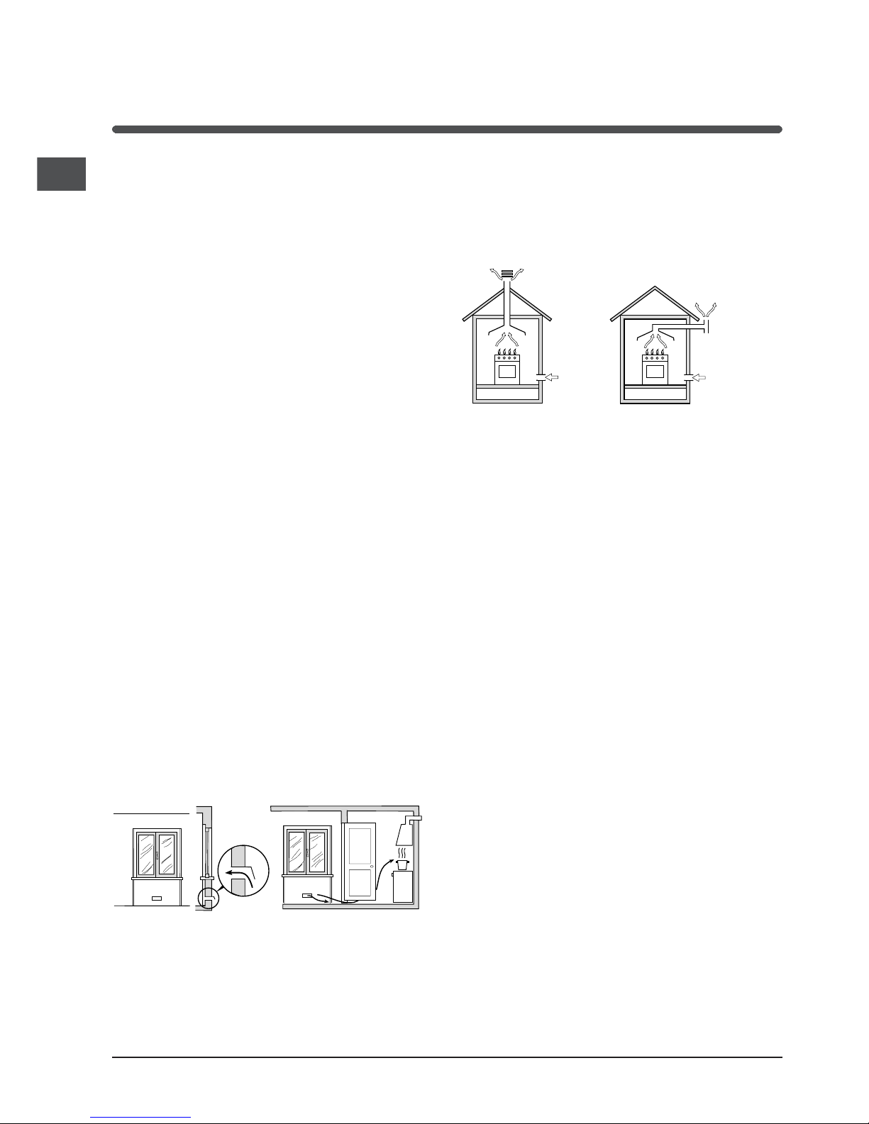
Room ventilation
The appliance may only be installed in permanentlyventilated rooms, according to current national
legislation. The room in which the appliance is
installed must be ventilated adequately so as to
provide as much air as is needed by the normal gas
combustion process (the flow of air must not be lower
than 2 m
3
/h per kW of installed power).
The air inlets, protected by grilles, should have a duct
with an inner cross section of at least 100 cm
2
and
should be positioned so that they are not liable to
even partial obstruction (see figure A).
These inlets should be enlarged by 100% - with a
minimum of 200 cm
2
- whenever the surface of the hob
is not equipped with a flame failure safety device.
When the flow of air is provided in an indirect manner
from adjacent rooms (see figure B), provided that
these are not communal parts of a building, areas with
increased fire hazards or bedrooms, the inlets should
be fitted with a ventilation duct leading outside as
described above.
After prolonged use of the appliance, it is advisable to
open a window or increase the speed of any fans used.
Disposing of combustion fumes
The disposal of combustion fumes should be
guaranteed using a hood connected to a safe and
efficient natural suction chimney, or using an electric
fan that begins to operate automatically every time the
appliance is switched on (see figure).
The liquefied petroleum gases are heavier than air
and collect by the floor, therefore all rooms containing
LPG cylinders must have openings leading outside so
that any leaked gas can escape easily.
LPG cylinders, therefore, whether partially or
completely full, must not be installed or stored in
rooms or storage areas that are below ground level
(cellars, etc.). Only the cylinder being used should be
stored in the room; this should also be kept well away
from sources of heat (ovens, chimneys, stoves) that
may cause the temperature of the cylinder to rise
above 50°C.
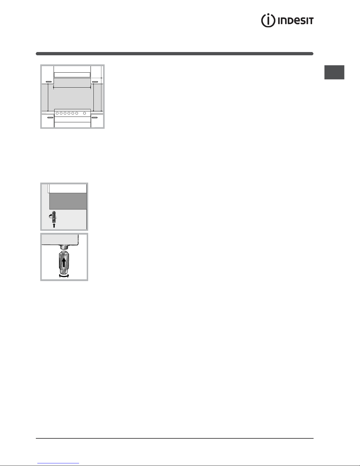
Positioning and levelling
It is possible to install the appliance alongside
cupboards whose height does not exceed that of the
hob surface.
Make sure that the wall in contact with the back of
the appliance is made from a non-flammable, heatresistant material (T 90°C).
To install the appliance correctly:
Place it in the kitchen, dining room or the bed-sit
(not in the bathroom).
If the top of the hob is higher than the cupboards,
the appliance must be installed at least 200 mm
away from them.
If the cooker is installed underneath a wall cabinet,
there must be a minimum distance of 420 mm
between this cabinet and the top of the hob.
Installation
Adjacent room Room requiring
ventilation
A
B
Ventilation opening for
comburent air
Increase in the gap
between the door and
the flooring
A
Fumes channelled
straight outside
Fumes channelled through a
chimney or a branched flue
system (reserved for cooking
appliances)
GB
3
If the cooker is
installed underneath a
wall cabinet, there must
be a minimum distance
of 420 mm between this
cabinet and the top of
the hob.
This distance should be
increased to 700 mm if
the wall cabinets are
flammable (see figure).
Do not position blinds behind the cooker or less
than 200 mm away from its sides.
Any hoods must be installed according to the
instructions listed in the relevant operating manual.
Levelling
If it is necessary to level the
appliance, screw the adjustable
feet into the places provided on
each corner of the base of the
cooker (see figure).
The legs* fit into the slots on
the underside of the base of
the cooker.
Electrical connection
Install a standardised plug corresponding to the load
indicated on the appliance data plate (see Technical
data table).
The appliance must be directly connected to the
mains using an omnipolar circuit-breaker with a
minimum contact opening of 3 mm installed between
the appliance and the mains. The circuit-breaker must
be suitable for the charge indicated and must comply
with NFC 15-100 regulations (the earthing wire must
not be interrupted by the circuit-breaker). The supply
cable must be positioned so that it does not come into
contact with temperatures higher than 50°C at any
point.
Before connecting the appliance to the power supply,
make sure that:
The appliance is earthed and the plug is compliant with
the law.
The socket can withstand the maximum power of the
appliance, which is indicated by the data plate.
HOOD
420
Min.
min. 650 mm. with hood
min.
700 mm. without hood
mm.
600
Min. mm.
420
Min. mm.
The voltage is in the range between the values
indicated on the data plate.
The socket is compatible with the plug of the
appliance. If the socket is incompatible with the
plug, ask an authorised technician to replace it. Do
not use extension cords or multiple sockets.
Once the appliance has been installed, the power
supply cable and the electrical socket must be easily
accessible.
The cable must not be bent or compressed.
The cable must be checked regularly and replaced
by authorised technicians only.
The manufacturer declines any liability should
these safety measures not be observed.
Gas connection
Connection to the gas network or to the gas cylinder
may be carried out using a flexible rubber or steel hose,
in accordance with current national legislation and after
making sure that the appliance is suited to the type of
gas with which it will be supplied (see the rating sticker
on the cover: if this is not the case see below). When
using liquid gas from a cylinder, install a pressure
regulator which complies with current national
regulations. To make connection easier, the gas supply
may be turned sideways*: reverse the position of the
hose holder with that of the cap and replace the gasket
that is supplied with the appliance.
Check that the pressure of the gas supply is
consistent with the values indicated in the Table of
burner and nozzle specifications (see below). This will
ensure the safe operation and durability of your
appliance while maintaining efficient energy
consumption.
Gas connection using a flexible rubber hose
Make sure that the hose complies with current
national legislation. The internal diameter of the hose
must measure: 8 mm for liquid gas supply; 13 mm for
methane gas supply.
Once the connection has been performed, make sure
that the hose:
Does not come into contact with any parts that
reach temperatures of over 50°C.
Is not subject to any pulling or twisting forces and
that it is not kinked or bent.
Does not come into contact with blades, sharp
corners or moving parts and that it is not
compressed.
4
GB
Is easy to inspect along its whole length so that its
condition may be checked.
Is shorter than 1500 mm.
Fits firmly into place at both ends, where it will be
fixed using clamps that comply with current
regulations.
If one or more of these conditions is not fulfilled or if
the cooker must be installed according to the
conditions listed for class 2 - subclass 1 appliances
(installed between two cupboards), the flexible steel
hose must be used instead (see below).
Connecting a flexible jointless stainless steel pipe
to a threaded attachment
Make sure that the hose and gaskets comply with
current national legislation.
To begin using the hose, remove the hose holder on
the appliance (the gas supply inlet on the appliance is
a cylindrical threaded 1/2 gas male attachment).
Perform the connection in such a way that the hose
length does not exceed a maximum of 2 metres,
making sure that the hose is not compressed and
does not come into contact with moving parts.
Checking the tightness of the connection
When the installation process is complete, check the
hose fittings for leaks using a soapy solution. Never
use a flame.
Adapting to different types of gas
It is possible to adapt the appliance to a type of gas
other than the default type (this is indicated on the
rating label on the cover).
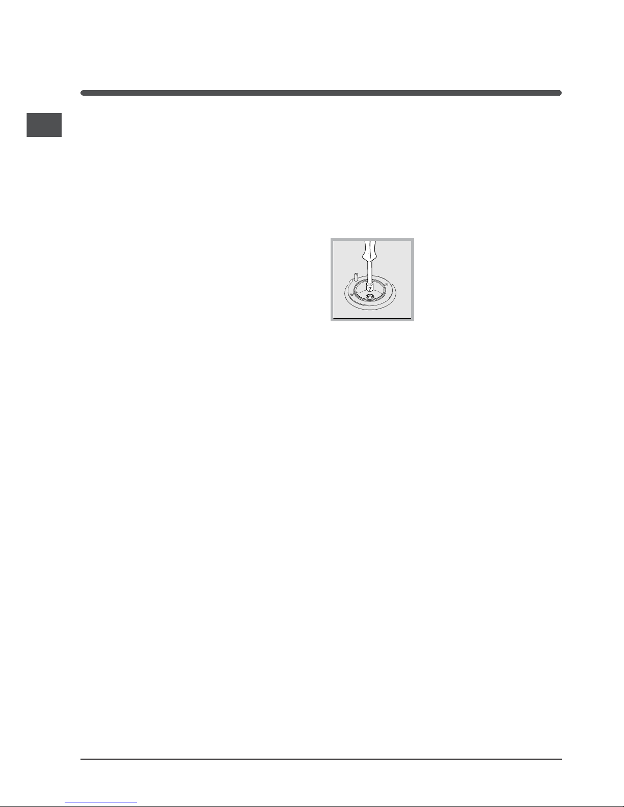
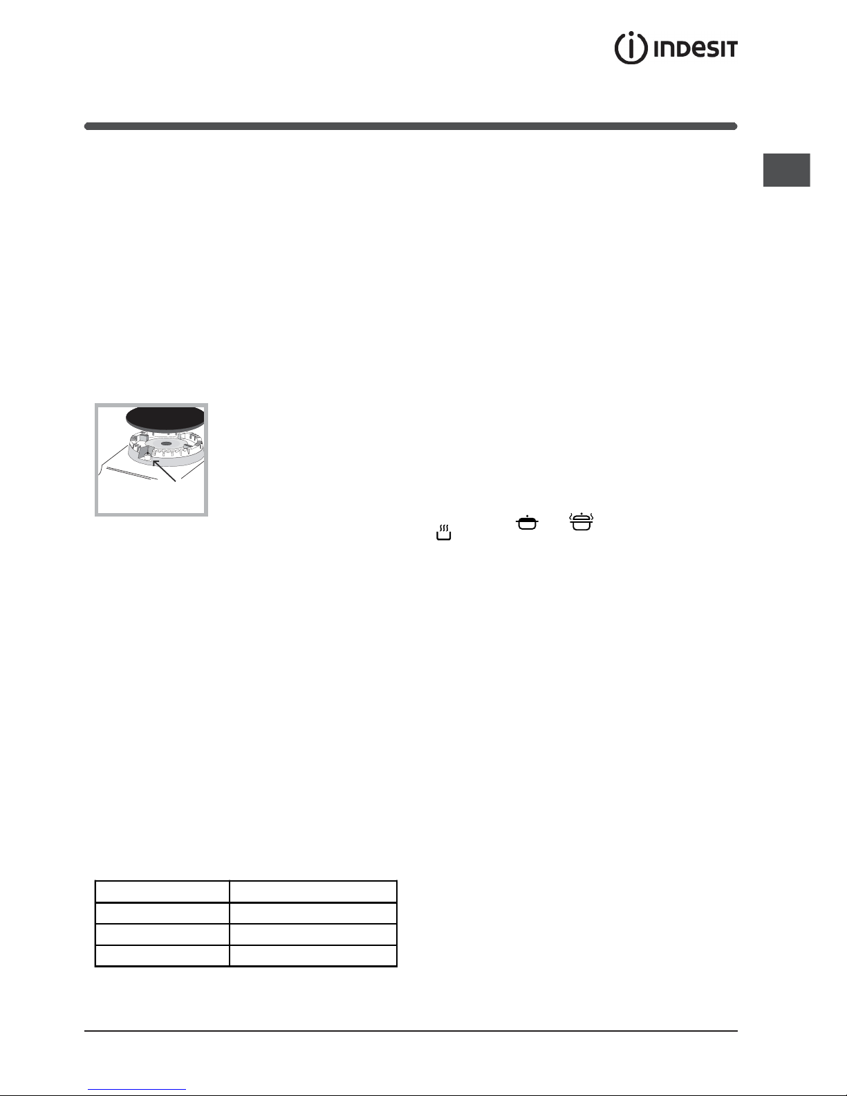
Adapting the hob
Replacing the nozzles for the hob burners:
1. Remove the hob grids and slide the burners off their
seats.
2. Unscrew the nozzles using a
7 mm socket spanner (see
figure), and replace them with
nozzles suited to the new type
of gas (see Burner and nozzle
specifications table).
3. Replace all the components
by following the above
instructions in reverse.
Adjusting the hob burners minimum setting:
1. Turn the tap to the minimum position.
2. Remove the knob and adjust the regulatory screw,
which is positioned inside or next to the tap pin, until
the flame is small but steady.
If the appliance is connected to a liquid gas supply,
the regulatory screw must be fastened as tightly as
possible.
3. While the burner is alight, quickly change the position of
the knob from minimum to maximum and vice versa
several times, checking that the flame is not extinguished.
The hob burners do not require primary air adjustment.
After adjusting the appliance so it may be used with a
different type of gas, replace the old rating label with a new
one that corresponds to the new type of gas (these labels
are available from Authorised Technical Assistance
Centres).
Should the gas pressure used be different (or vary
slightly) from the recommended pressure, a suitable
pressure regulator must be fitted to the inlet hose in
accordance with current national regulations relating to
regulators for channelled gas.
GB
5
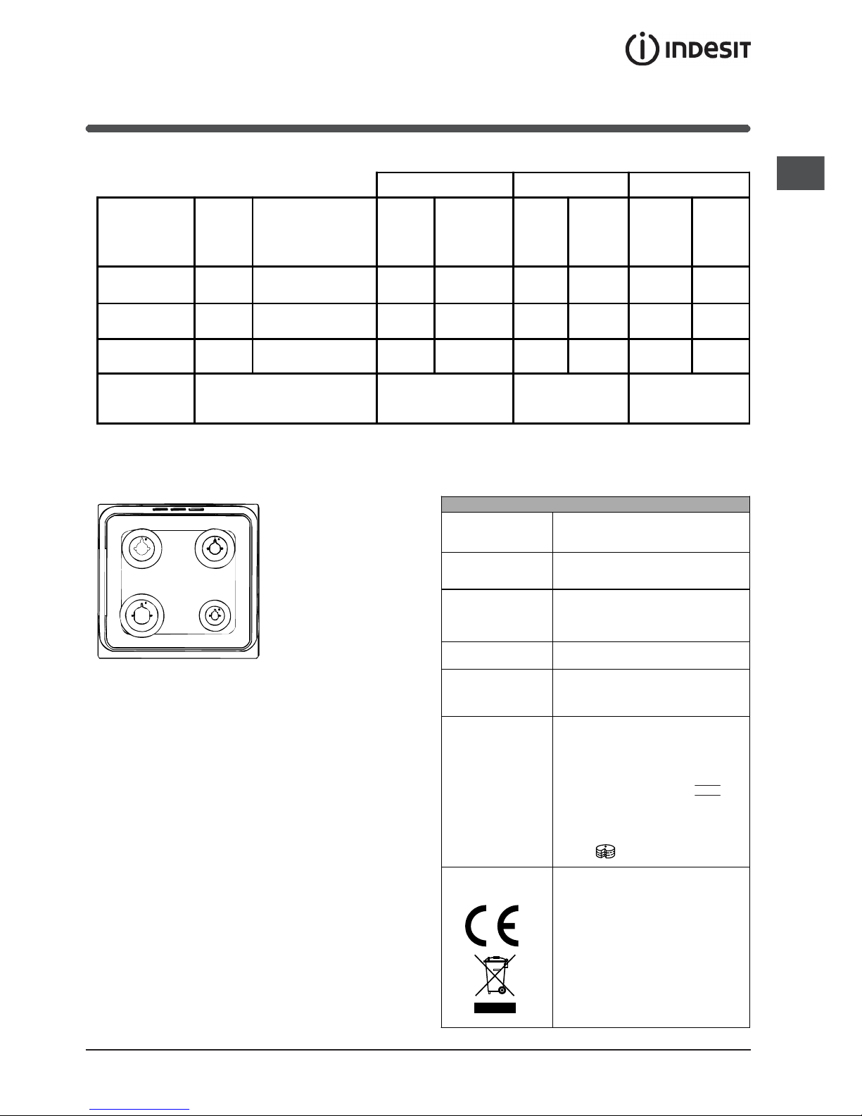
Table of burner and nozzle specifications
Tabl e 1
Natural Gas GZ 50 Natural Gas GZ 35 GPB-B
Burner Diameter
(mm)
Thermal power
(p.c.i.*)
Nozzle
1/100
Flow*
l/h
Nozzle
1/100
Flow*
l/h
Nozzle
1/100
Flow*
g/h
kW (mm) (mm) (mm)
Fast
(Large)(R)
100 2,70 116 285 183 398 86 225
Semi Fast
(Medium)(S)
75 1,70 106 180 143 251 70 142
Auxiliary
(Small)(A)
55 0,90 79 95 106 133 50 75
Supply
Pressures
Nominal (mbar)
Minimum (mbar)
Maximum (mbar)
16
20
25
10
13
16
29
36
44
* A 0°C e 1013 mbar-dry gas
GZ 50 p.c.i. 35.9 MJ/m³
GZ 35 p.c.i. 25.8 MJ/m³
GPB-B p.c.i. 123.6 MJ/m³
S
S
R
A
K6G56S.A /U
K6G52.A /U
TABLE OF CHARACTERISTSICS
Dimensions
width 43, 5 cm
height 32 cm
depth 40 cm
Volume
56 l
Useful
measurements
relating to the oven
compartment
width 46 cm
height 8,5 cm
depth 44 cm
Burners
may be adapted for use with any type
of gas shown on the data plate.
Voltage and
frequency
see data plate
ENERGY LABEL
Directive 2002/40/EC on the label of
electric ovens.
Standard EN 50304
Energy consumption for Natural
convection – heating mode:
Convection;
Declared energy consumption for
Forced convection Class – heating
mode: Baking
This appliance conforms to the
following European Economic
Community directives: 2006/95/CEE
dated 12/12/06 (Low Voltage) and
subsequent amendments 89/336/EEC dated 03/05/89
(Electromagnetic Compatibility) and
subsequent amendments 90/369/EEC dated 29/06/90 (Gas) and
subsequent amendments - 93/68/EEC
dated 22/07/93 and subsequent
amendments.
2002/96/EEC
6
GB
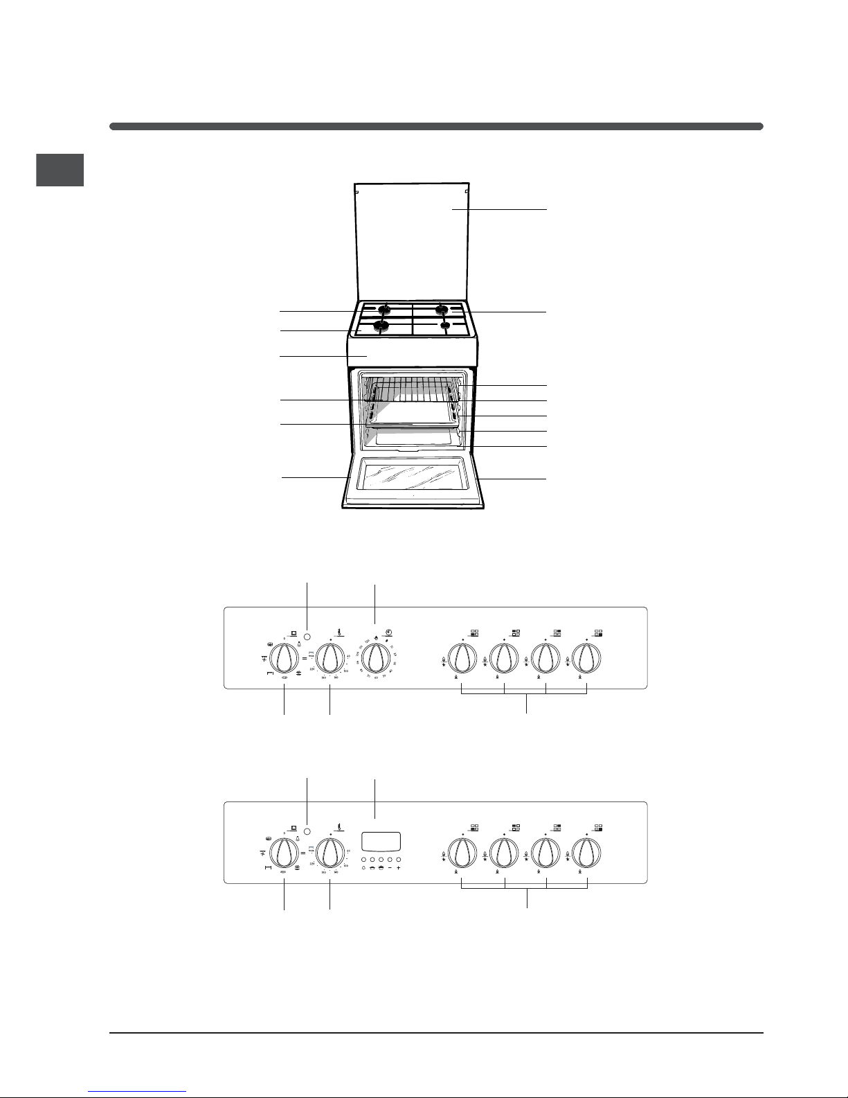
Description
of the appliance
Overall view
Control panel
*
Only available in certain models.
BURNER
control knobs
SELECTOR
knob
THERMOSTAT
knob
THERMOSTAT
indicator light
COOKING TIMER knob*
BURNER
control knobs
SELECTOR
knob
THERMOSTAT
knob
THERMOSTAT
indicator light
Electronic
programmer*
Hob grid
Glass cover*
Control panel
GRILL rack
DRIPPING PAN
GUIDE RAILS
for the sliding racks
position 3
position 2
position 1
Gas burner
Containment
surface for spills
Adjustable foot
Adjustable foot
position 5
position 4
GB
7
Start-up and use
Using the hob
Lighting the burners
For each BURNER knob there is a full ring showing
the strength of the flame for the relevant burner.
To light one of the burners on the hob:
1. Bring a flame or gas lighter close to the burner.
2. Press the BURNER knob and turn it in an
anticlockwise direction so that it is pointing to the
maximum flame setting E.
3. Adjust the intensity of the flame to the desired
level by turning the BURNER knob in an
anticlockwise direction. This may be the minimum
setting C, the maximum setting E or any position in
between the two.
If the appliance is fitted with
an electronic lighting device*
(see figure), press the
BURNER knob and turn it in
an anticlockwise direction,
towards the minimum flame
setting, until the burner is lit.
The burner may be
extinguished when the knob is released. If this
occurs, repeat the operation, holding the knob down
for a longer period of time.
If the flame is accidentally extinguished, switch off
the burner and wait for at least 1 minute before
attempting to relight it.
The appliance is equipped with a flame failure safety
device; press and hold the BURNER knob for
approximately 2-3 seconds to keep the flame alight
and to activate the device.
To switch the burner off, turn the knob until it
reaches the stop position .
Practical advice on using the burners
For the burners to work in the most efficient way
possible and to save on the amount of gas
consumed, it is recommended that only pans that
have a lid and a flat base are used. They should
also be suited to the size of the burner:
Burner ø Cookware diameter (cm)
Fast (R) 24 - 26
Semi Fast (S) 16 - 20
Auxiliary (A) 10 - 14
To identify the type of burner, please refer to the
diagrams contained in the Burner and nozzle
specifications.
Using the oven
The first time you use your appliance, heat the
empty oven with its door closed at its maximum
temperature for at least half an hour. Ensure that the
room is well ventilated before switching the oven off
and opening the oven door. The appliance may emit
a slightly unpleasant odour caused by protective
substances used during the manufacturing process
burning away.
Before operating the product, remove all plastic
film from the sides of the appliance.
Never put objects directly on the bottom of the
oven; this will avoid the enamel coating being
damaged.
Should the appliance be equipped with an
electronic programmer*, to use the electric oven, just
press buttons
and at the same time (the
symbol will appear on the display) before
selecting the desired cooking function.
1. Select the desired cooking mode by turning the
SELECTOR knob.
2. Select the recommended temperature for the
cooking mode or the desired temperature by turning
the THERMOSTAT knob.
A list detailing cooking modes and suggested
cooking temperatures can be found in the relevant
table (see Oven cooking advice table).
During cooking it is always possible to:
Change the cooking mode by turning the
SELECTOR knob.
Change the temperature by turning the
THERMOSTAT knob.
Stop cooking by turning the SELECTOR knob to
the 0 position.
Always place cookware on the rack(s) provided.
THERMOSTAT indicator light
When this is illuminated, the oven is generating
heat. It switches off when the inside of the oven
reaches the selected temperature. At this point the
light illuminates and switches off alternately,
indicating that the thermostat is working and is
maintaining the temperature at a constant level.
*
Only available in certain models.
8
GB
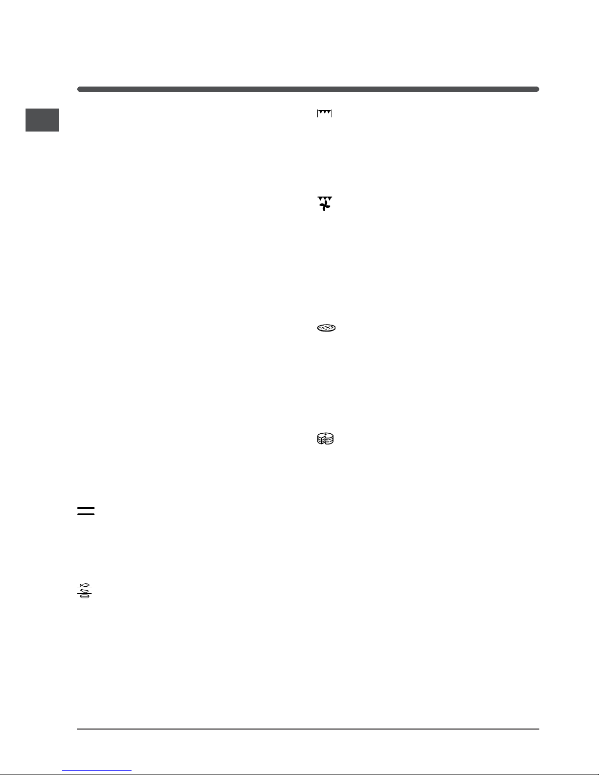
BARBECUE mode
The top heating element comes on.
The high and direct temperature of the grill is
recommended for food that requires high surface
temperature. Always cook in this mode with the oven
door closed.
GRATIN mode
The top heating element, as well as the fan, will
come on. This combination of features increases the
effectiveness of the unidirectional thermal radiation
of the heating elements through forced circulation of
the air throughout the oven. This helps prevent food
from burning on the surface, allowing the heat to
penetrate right into the food. Always cook in this
mode with the oven door closed.
PIZZA mode
The bottom and circular heating elements, as well as
the fan, will come on. This combination heats the
oven rapidly by producing a considerable amount of
heat, particularly from the bottom element. If you
use more than one rack simultaneously, switch the
position of the dishes halfway through the cooking
process.
BAKING mode
The rear heating element and the fan come on,
guaranteeing the distribution of heat delicately and
uniformly throughout the oven. This mode is ideal for
baking and cooking temperature sensitive foods
such as cakes that need to rise and to prepare
certain tartlets on 3 shelves simultaneously.
Practical cooking advice
! Do not place racks in position 1 and 5 during fan-
assisted cooking. Excessive direct heat can burn
temperature sensitive foods.
! In the BARBECUE and GRATIN cooking modes,
place the dripping pan in position 1 to collect
cooking residues (fat and/or grease).
MULTI-COOKING
Use position 2 and 4, placing the food that
requires more heat on 2.
Oven light
This is switched on by turning the SELECTOR knob
to any position other than 0. It remains lit as long
as the oven is operating. By selecting
& with the
knob, the light is switched on without any of the
heating elements being activated.
Using the cooking timer*
1. To set the buzzer, turn the COOKING TIMER knob
clockwise almost one complete revolution.
2. Turn the knob anticlockwise to set the desired
time: align the minutes shown on the COOKING
TIMER knob with the indicator on the control panel.
3. When the selected time has elapsed, a buzzer
sounds and the oven turns off.
4. When the oven is off the cooking timer can be
used as a normal timer.
To use the oven manually, in other words when you
do not wish to use the end of cooking timer, turn the
COOKING TIMER knob until it reaches the 9
symbol.
Cooking modes
! A temperature value can be set for all cooking
modes between 60°C and Max, except for
BARBECUE (recommended: set only to MAX
power level);
GRATIN (recommended: do not exceed 200°C).
TRADITIONAL OVEN mode
Both the top and bottom heating elements will come
on. With this traditional cooking mode, it is best to
use one cooking rack only: if more than one rack is
used, the heat will be distributed unevenly.
MULTI-COOKING mode
All the heating elements (top, bottom and circular),
as well as the fan, will come on. Since the heat
remains constant throughout the oven, the air cooks
and browns food uniformly. A maximum of two racks
may be used at the same time.
GB
9
*
Only available in certain models.
4. After the time has elapsed a buzzer will sound,
and this can be switched off by pressing any button
(except the + and - buttons). The symbol
will
switch off.
The timer does not switch the oven on or off.
Adjusting the volume of the buzzer
After selecting and confirming the clock settings,
use the - button to adjust the volume of the alarm
buzzer.
Setting the cooking time with a delayed start
First decide which cooking mode you wish to use
and set a suitable temperature using the SELECTOR
and THERMOSTAT knobs on the oven.
At this point it is possible to set the cooking time:
1. Press the COOKING TIME button
.
2. Within 4 seconds of having pressed this button,
set the desired amount of time by pressing the + and
- buttons. If, for example, you wish to set a cooking
time of 30 minutes, the display will show:
N
3. 4 seconds after the buttons are released, the
current time (for example 10.00) reappears on the
display with the symbol
m
and the letter A (AUTO).
Next the desired cooking end time must be set:
4. Press the END COOKING TIME button
.
5. Within 4 seconds of having pressed this button,
adjust the cooking end time by pressing the + and buttons. If, for example, you want cooking to end at
13.00, the display shows:
O
6. 4 seconds after the buttons are released, the
current time (for example 10.00) reappears on the
display with the letter A (AUTO).
P
At this point, the oven is programmed to switch on
automatically at 12:30 and switch off after 30
minutes, at 13.00.
Setting the cooking time with an immediate start
Follow the above procedure for setting the cooking
time (points 1-3).
When the letter A appears, this indicates that both
the cooking time and the end cooking time have
been programmed in AUTO mode. To restore the
oven to manual operation, after each AUTO cooking
mode press the COOKING TIME
and END
Place the dripping pan on the bottom and the rack
on top.
BARBECUE
Insert the rack in position 3 or 4. Place the food in
the centre of the rack.
We recommend that you set the maximum power
level. The top heating element is regulated by a
thermostat and may not always be on.
PIZZA MODE
Use a light aluminium pizza pan. Place it on the
rack provided.
For a crispy crust, do not use the dripping pan
(prevents crust from forming by extending cooking
time).
If the pizza has a lot of toppings, we recommend
adding the mozzarella cheese on top of the pizza
halfway through the cooking process.
Planning cooking with the electronic
programmer*
Setting the clock
After the appliance has been connected to the power
supply, or after a blackout, the display will
automatically reset to 0:00 and begin to blink. To set
the time:
1. Press the COOKING TIME button
and the
COOKING END TIME
simultaneously.
2. Within 4 seconds of having pressed these
buttons, set the exact time by pressing the + and buttons. The + button advances the hours and the
button decreases the hours.
Once the time has been set, the programmer
automatically switches to manual mode.
Setting the timer
The timer enables a countdown to be set, when the
time has elapsed a buzzer sounds.
To set the timer proceed as follows:
1. press the TIMER button
. The display shows:
N.
2. Press the + and - buttons to set the desired time.
3. When the buttons are released the timer begins
counting down and the current time appears on the
display.
R
 Loading...