


For Husqvarna Parts Call 606-678-9623 or 606-561-4983
Rider 850, Rider 970,
Rider 850 HST, Rider 970 HST,
Rider 1030 Bioclip, Rider 1200
Workshop Manual
101 89 11-26
www.mymowerparts.com

For Husqvarna Parts Call 606-678-9623 or 606-561-4983
Workshop manual
Rider 850, Rider 970,
Rider 850 HST, Rider 970 HST,
Rider 1030 Bioclip, Rider 1200
Contents
Safety regulations ............................................... 2
General instructions ........................................ 2
Special instructions ......................................... 2
Special tools ........................................................ 3
Technical data .....................................................4
Dimensions .......................................................4
Engine ..............................................................4
Gear box ..........................................................4
Transmission....................................................4
Control points ...................................................4
Play ..................................................................4
Tightening moments........................................ 4
Delivery measures...............................................5
Measures before delivery ................................ 5
Fastening steering wheel ........................... 5
Fastening seat.............................................5
Fastening support wheels .......................... 6
Fastening safety guard............................... 6
Refilling battery acid ................................... 6
Design and function .......................................... 7
General ............................................................7
Engine ..............................................................8
Steering............................................................9
Driving ............................................................10
Mowing deck ..................................................11
Reparation instructions ................................... 12
Removing engine ...........................................12
Replacing engine............................................14
Checking and adjusting steering wires .......... 17
Replacing steering wires ............................... 18
Removal/installation of steering axle ............. 18
Removal/installation of wire wheel ................ 19
Checking and adjusting brake wire................ 20
Checking and adjusting Rider 850/970..... 20
Checking and adjusting Rider
1030 Bioclip/1200..................................... 20
Checking and adjusting gear control
Rider 850/970.................................................21
Checking and adjusting throttle control
Rider 1030 Bioclip/1200 ................................ 21
Checking and adjusting freewheel clutch
Rider 850/970.................................................22
Replacing articulated steering bearing .......... 22
Removal of swing axle .................................. 24
Installation of swing axle ............................... 24
Removal/installation of gear box ................... 25
Removal/installation of hydrostatic transmission
Rider 850 HST/970 HST ............................... 26
Removal/installation of hydrostatic transmission
Rider 1030/1200.............................................27
Replacing hydrostat. trans. axle seals........... 29
Ingoing axle...............................................2 9
Outgoing axles ..........................................30
Hydrostatic transmission brake ..................... 31
Removal of brake ..................................... 31
Installation of brake .................................. 31
Adjustment of brake ................................. 32
Bleeding hydrostatic transmission oil system 33
Adjustment of transmission neutral position .. 33
Transmission maintenance............................ 34
Oil change .................................................34
Ineffective brake power ............................ 34
Checking and adjusting cutting unit ground.......
pressure Rider 970/1030 Bioclip/1200........... 35
Checking and adjusting parallelism of the .........
mowing deck ..................................................35
Adjusting Rider 1030 Bioclip/1200............ 35
Adjusting Rider 850 .................................. 36
Adjusting Rider 970 .................................. 36
Adjusting cutting height area ......................... 36
Removal of mowing deck Rider 1030
and Rider 1200...............................................37
Removal of mowing deck Rider 970.............. 37
Removal of mowing deck Rider 850.............. 38
Replacing cutting unit belts ........................... 38
Belt replacement on bioclip-unit ............... 38
Belt replacement on mowing deck with side-
or rear discharge ...................................... 39
Removal of blades with bearings................... 40
Grinding and balancing of blades .................. 41
Electrical system ...............................................42
Circuit diagram Rider 850.............................. 42
Circuit diagram Rider 970.............................. 43
Circuit diagram Rider 850/970 HST............... 44
Circuit diagram Rider 1030 Bioclip/1200 ....... 45
www.mymowerparts.com
English – 1

For Husqvarna Parts Call 606-678-9623 or 606-561-4983
Safety regulations
General instructions
The workshop handbook is written for personnel who
are assumed to have general ride-on mower
reparation and service know-how.
The workshop where the ride-on mower is repaired
should be equipped with safety devices in
accordance with local regulations.
No-one should attempt to repair the ride-on mower
without having first read and understood the contents
of this handbook.
The machine is tested for safety and approved only
for equipment supplied or recommended by the
manufacturer.
The below-mentioned boxes are included in this
workshop handbook, as is appropriate.
WARNING!
!
IMPORTANT INFORMATION
This box indicates a risk of damage to the
material if the instructions are not
followed.
The warning box indicates a
risk of injury to persons if the
instructions are not followed.
Special instructions
The fuel used in the ride-on mower has the
following hazardous characteristics:
• Toxic fluid and fumes
• Can cause eye and skin complaints
• Can cause breathing difficulties
• Highly flammable
When using compressed air, do not direct the
compressed air stream towards your, or anybody
else's, body. Air can be forced into the blood
stream, thereby constituting a danger to life .
Use hearing protectors when test driving.
After test driving, do not touch the silencer before it
has cooled down. Risk of burn injuries. This
especially applies if the ride-on mower is equipped
with a catalytic converter. If consumed, the lining on
and in the catalytic converter element is dangerous
to health. Use protective gloves when working with
the catalytic converter/silencer.
The blades are sharp and can cause cutting
injuries. Always use protective gloves when you are
handling the blades.
Use protective glasses when working with the
mowing deck. If the belt's tension spring comes off
and flies upwards, this can cause injury to persons.
Be extra careful when handling battery acid. Spilling
acid on the skin can cause severe burn injuries. If
acid is spilt on the skin, rinse immediately with
water. If acid gets into the eyes, this can cause
blindness. Contact a doctor.
2 – English
Be careful with the maintenance of the battery.
Explosive gas is formed in the battery. Never
handle the battery when smoking or in the vicinity of
naked flames or sparks. Otherwise, the battery can
explode and cause severe injuries.
www.mymowerparts.com

For Husqvarna Parts Call 606-678-9623 or 606-561-4983
Special tools
The following special tools are used when working on the ride-on mower.
506 66 48-01 506 79 06-01506 57 00-01 506 89 92-01506 56 76-01 506 89 93-01
506 56 76-01 Ball-ended Allen key 5/16" to unscrew
the engine pulley socket head cap
screw (Kawazaki).
506 57 00-01 Wheel puller for Rider 850 and Rider
970.
506 66 48-01 Puller for engine pulley.
506 79 06-01 Ball-ended Allen key 3/8" to unscrew
the engine pulley socket head cap
screw (Briggs & Stratton).
506 89 92-01 Holder-on for engine pulley removal.
506 89 93-01 Tool for removing steer return spring.
www.mymowerparts.com
English – 3

For Husqvarna Parts Call 606-678-9623 or 606-561-4983
T echnical data
Dimensions
Rider 850/850 HST Rider 970/970 HST
Length 2000 mm 2145 mm
Width 960 mm 1050 mm (970)
1260 mm (970 S)
1 120 mm (970-Bioclip)
Height 1060 mm 1060 mm
Unladen weight 225 kg 240 kg
Wheel base 820 mm 855 mm
Track 610 mm Front: 715 mm
Rear: 610 mm
Front: 710 mm (970-Bioclip)
Rear: 620 mm (970-Bioclip)
Tyre size 16x6, 50x8 16x6, 50x8
Rider 1030 Bioclip Rider 1200
Length 2300 mm 2300 mm
Width 1120 mm 1280 mm
Height 1085 mm 1085 mm
Unladen weight 300 kg 300 kg
Wheel base 855 mm 855 mm
Track 710 mm 710 mm
Tyre size 18x7, 50x8 18x7, 50x8
T ransmission
Rider 850 HST Rider 970 HST
Manufacture Kanzaki K55 Kanzaki K55
hydrostatic hydrostatic
Rider 1030 Bioclip Rider 1200
Manufacture Kanzaki K61 Kanzaki K61
hydrostatic hydrostatic
Control points
Mowing deck parallelism with cutting height
in pos. 1: ± 2 mm
Cutting height control in pos. 1: 850 = 37 ± 2 mm
Bioclip = 45 ± 2 mm
Other = 40 ± 2 mm
Synchronous transmission belt tension
Bioclip at 10 N force, impression: 7 mm
Dist. between support plate and drive belt: 3–6 mm
Distance belt tensioner control lever
and belt guide, disengaged unit: 17 ± 5 mm
Engine
Rider 850 Rider 850 HST
Manufacture Briggs & Stratton Briggs & Stratton
28B707, type 286707, type
0139, trim 01 0184, trim 01
Power 7.7/10.5 kW/hp 9.2/12.5 kW/hp
Displacement 362 cm
Oil volume 1.2 litres 1.2 litres
Rider 970/970 HST
Manufacture Briggs & Stratton Briggs & Stratton
28N707, type V-Twin, 350777
0189, trim 01 type 1123, trim A1
Power 11.4/15.5 kW/hp 13.7/18 kW/hp
Displacement
Oil volume 1.2 litre 1.3 litre
465 cm
3
3
465 cm
Rider 1030/1200
570 cm
3
3
Gear box
Rider 850 Rider 970
Manufacture
Europe Peerless Peerless
MST 205-531A MST 205-531A
USA Peerless Peerless
MST 205-530A MST 205-530A
Gears, forwards 5 5
Gears, reverse 1 1
Play
Clutch wire: 8–10 mm
Brake control lever against stop bolt: 0–1 mm
Brake control lever: 7–9 mm
Brake wire hydrostatic transmission: 0 mm
Tightening moments
Carrier steering 5–10 Nm
Pulley steering wire 20–30 Nm
Belt wheel 35–40 Nm
Blades 45–50 Nm
Blade bearings 20–25 Nm
Belt tensioner wheel 15–25 Nm
Holder screws, engine 20–25 Nm
Holder screws, gear box 20–25 Nm
Brake drum bolts hydrostatic transmission 27 Nm
Engine pulley 70–80 Nm
Wheel axle nut 100–150 Nm
4 – English
www.mymowerparts.com

For Husqvarna Parts Call 606-678-9623 or 606-561-4983
Delivery measures
Measures before delivery
A Husqvarna Rider is delivered from the factory on
a pallet and wrapped in plastic. For reasons of
space, certain measures must be carried out on the
ride-on mower before it can be delivered to the
customer.
Fastening steering wheel
• Fasten the steering wheel with steering column
on the steering shaft.
• Tighten the socket head cap screw, make sure
that it sits in its groove on the steering shaft.
• Securely lock the socket head cap screw with
the locking nut.
The following must be carried out by the dealer
before delivery:
• The steering wheel must be fastened.
• The seat must be fastened.
• On Rider 850, the support wheels are to be
fastened on the mowing deck.
• Safety guard is to be fastened on Rider 1030
Bioclip and Rider 1200.
• The battery must be filled with battery acid before
it is used.
Fastening seat
Insert the seat pin through the hole in the frame and
seat attachment and fasten spring pin.
IMPORTANT INFORMATION
On Rider 1030 Bioclip and Rider 1200 the
safety system contact is to be assembled
under the seat. Check the correct
functioning of the contact after delivery
measures have been carried out. The
machine should not function if there is noone sitting in the driver's seat.
www.mymowerparts.com
English – 5

For Husqvarna Parts Call 606-678-9623 or 606-561-4983
Before delivery
Fastening support wheels Refilling battery acid
RIDER 850RIDER 850RIDER 850
Fasten the support wheels with axles, spacers and
nuts in the support wheels holder.
The battery is delivered dry from the factory.
• Slowly fill the battery acid up to the mark on the
battery.
Fastening safety guard
• Wait 20 minutes and fill, as is required, with more
battery acid.
On Rider 1030 Bioclip and Rider 1200, a safety
guard is to be assembled.
Screw the four accompanying screws into the
engine guard holder.
• Charge the battery (12V, 6A) for one hour.
• Check the level of acid and fill, as is required,
with distilled water up to the correct level.
!
The battery acid is highly corrosive. Use
rubber gloves and protective glasses. Avoid
breathing in the acid fumes.
External: Rinse thoroughly with water.
Internal: Drink large quantities of water or
Eyes: Rinse thoroughly with water.
The battery gives off explosive gas. Sparks,
naked flames and cigarettes must absolutely
not be in the near vicinity of the battery.
WARNING!
Measures for contact with acid
milk. Contact a doctor as soon as
possible.
Contact a doctor as soon asap.
6 – English
www.mymowerparts.com

For Husqvarna Parts Call 606-678-9623 or 606-561-4983
Design and function
General
Husqvarna Riders is a series of ride-on mowers
with a large capacity. There are four sizes, from the
smallest Rider 850 to the largest Rider 1200 (the
figures indicate the cutting width in mm).
All Riders have articulated steering in order to
easily cut around trees and other obstacles.
Moreover, they all have front-mounted mowing
decks for controlled cutting and for best possible
cutting results.
RIDER 850RIDER 850RIDER 850
RIDER 850RIDER 850RIDER 850
Husqvarna Riders can, moreover, be equipped
with various accessories such as moss rake and
dozer blade which make them flexible working
tools throughout the year.
Rider 850 and Rider 970 can be delivered with a
manual gear box or with hydrostatic transmission.
Rider 1030 and Rider 1200 are only available with
hydrostatic transmission.
RIDER 970RIDER 970RIDER 970
Rider 850 has a mowing deck with rear ejection. Rider 970 can be delivered with three different
mowing decks; with rear ejection, side ejection or,
as the picture shows, with a bioclip-deck.
Rider 1030 Bioclip. This is the larger Rider model.
It is technically similar to the Rider 1200, apart
from the fact that it has a bioclip-deck.
Rider 1200 has a mowing deck with rear ejection.
www.mymowerparts.com
English – 7

For Husqvarna Parts Call 606-678-9623 or 606-561-4983
Design and function
Engine
All Husqvarna Riders have engines from Briggs &
Stratton. Rider 850 and Rider 970 have singlecylinder engines whilst Rider 1030 Bioclip and
Rider 1200 have two-cylinder engines. Both the
single and two-cylinder engines are air cooled.
More intricate engine repairs are not described in
this workshop handbook, these can instead be read
in Briggs & Stratton's own handbooks which contain
detailed information about adjusting and repairing
the engines. The handbooks can be ordered from
an authorized service workshop.
The order numbers for the respective handbooks
are found in the table below:
Model B & S art. no.
Rider 850 270962
Rider 970 270962
Rider 1030 805845
Rider 1200 805845
It is important that only original spare parts are
used when repairing the engines. If other parts are
used, the guarantee shall no longer be valid.
Rider 850 has a 10.5 or 12.5 hp single-cylinder side
valved engine with spray lubrication.
Rider 970 has a 15.5 hp single-cylinder, top valved
engine with spray lubrication.
Rider 1030 Bioclip and Rider 1200 have 18 hp twocylinder top valved engines with pressure
lubrication and a separate oil filter. These engines
can also be equipped with catalytic converters
which reduce hydrocarbon and nitrogen oxide
emissions by up to 65% and carbon monoxide
emissions by 45%.
8 – English
www.mymowerparts.com

For Husqvarna Parts Call 606-678-9623 or 606-561-4983
Design and function
Steering
All the ride-on mowers in Husqvarna's Rider-series
have articulated steering. The steering force from
the steering wheel is transferred to the rear section
via wires and a chain. This ensures that the ride-on
mower is easy to manoeuvre, as well as having
high-precision steering. A Rider easily cuts around
all obstacles that may be found on the lawn.
Thanks to the articulated steering, the turning
radius is extremely small, the uncut circle when the
steering wheel is fully turned is just 20 cm for the
Rider 850.
Outline diagram of the articulated steering function.
Rider 850 HST, Rider 970, Rider 970 HST, Rider
1030 Bioclip and Rider 1200 have a roller bearing
(1) steering column.
Rider 850 has a sliding bearing (2) steering column.
www.mymowerparts.com
English – 9

For Husqvarna Parts Call 606-678-9623 or 606-561-4983
Design and function
Driving
Rider 850 HST, Rider 970 HST, Rider 1030 Bioclip
and Rider 1200 are equipped with hydrostatic
transmission which provides the driver complete
control. Continuously variable speed control,
forwards and reverse, is by means of a foot pedal.
Rider 850 and Rider 970 have a manual gear box
with five forward gears, neutral and one reverse
gear. This gear box is an "inline" type, which means
that you can change from neutral to fifth gear
without having to go through all the other gears.
Manual gear box on Rider 850 and Rider 970. Hydrostatic transmission on Rider 1030 and Rider
1200.
Hydrostatic transmission on Rider 850 HST and
Rider 970 HST.
10 – English
www.mymowerparts.com
For Husqvarna Parts Call 606-678-9623 or 606-561-4983
Design and function
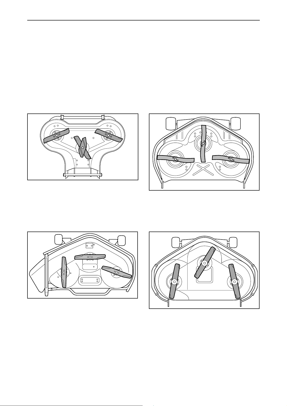
Mowing deck
The entire Rider-series is equipped with frontmounted, floating three-blade mowing decks for
effective cutting of uneven surfaces.
Rider 850 has a mowing deck with rear discharge
and a cutting width of 850 mm.
Rider 970 can be delivered with different types of
mowing deck: rear discharge, side discharge or
with a bioclip-deck. Rider 970 has a cutting width
of 965 mm, although the bioclip-version has a
cutting width of 1030 mm.
Rider 1030 Bioclip has a bioclip-deck and a cutting
width of 1030 mm.
Rider 1200 has a mowing deck with rear discharge
and a cutting width of 1200 mm.
Mowing deck on a Rider 850 (rear discharge).
Mowing deck on a Rider 970 S (side discharge).
Mowing deck on a Rider 1030 Bioclip (also used on
Rider 970 Bioclip).
Mowing deck on a Rider 1200 (rear discharge).
www.mymowerparts.com
English – 11

For Husqvarna Parts Call 606-678-9623 or 606-561-4983
Reparation instructions
Removing engine
1
Remove the battery's fixing belt. Remove the safety
guard and remove the cable connections. Then, lift
out the battery.
3
Mark up and remove the engine's electrical
connections.
2
Remove the cable which leads from the starter
relay to the start motor.
4
Remove the clamps which hold the throttle and
choke wires. Unhook the wires from their
attachment in the carburettor.
Rider 850/970 have just one wire which controls
both the throttle and the choke.
12 – English
www.mymowerparts.com
For Husqvarna Parts Call 606-678-9623 or 606-561-4983
Reparation instructions
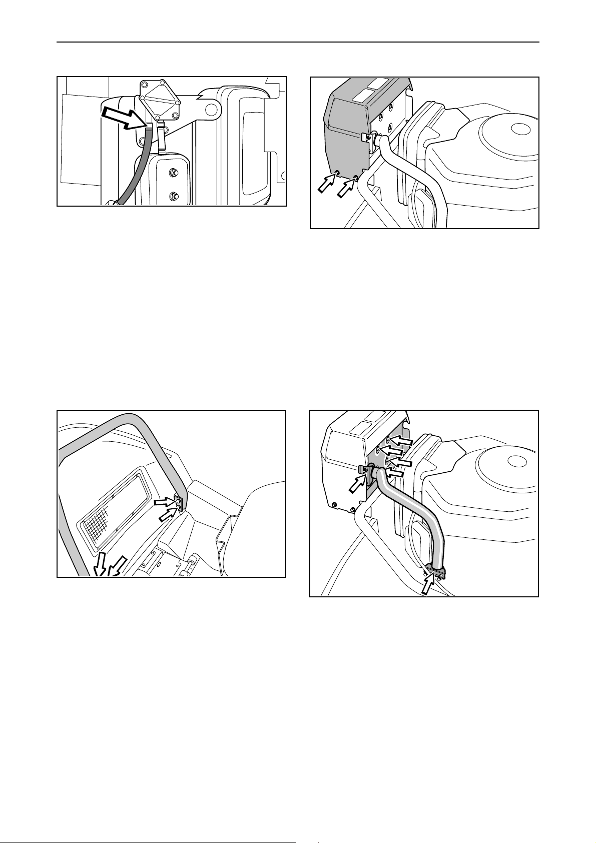
5
Remove the fuel line hose clamp from the fuel
pump and pull the fuel line downwards.
7
Remove the cover plate over the silencer (two screws
on either side of the silencer) and lift out the plate.
6
Unscrew the safety guard attachments, (two skrews
on each side) and lift out the safety guard.
Rider 850/970 do not have a safety guard.
8
Remove the exhaust pipe clamps and the silencer's
four holder screws. Then remove the silencer and
the exhaust pipe.
On Rider 850/970, the exhaust pipe is removed
without removing the silencer.
www.mymowerparts.com
English – 13

For Husqvarna Parts Call 606-678-9623 or 606-561-4983
Reparation instructions
911
1 2
Clamp together the wire holder under the engine
pulley with a pair of flat pliers and pull the wire
holder downwards.
Remove the engine attachments, two on each side
of the engine, and remove the engine from the
mower.
506 89 92-01
10
506 79 06-01
Insert tool no. 506 79 06-01 into the centre of the
engine pulley. Unscrew and remove the socket
head cap screw which holds the pulley and the
engine axle together. Use tool no. 506 89 92-01 as
a holder-on. Remove the pulley from the engine
axle.
Replacing engine
IMPORTANT INFORMATION
When installing the engine, it is important
that the pulley groove (1) is in a position so
the outgoing axle key (2) fits into the groove
(see diagram). Also check that both spacing
collars (3) and the key (2) are firmly attached
on the engine axle. Grease the engine axle.
14 – English
www.mymowerparts.com
 Loading...