


For Husqvarna Parts Call 606-678-9623 or 606-561-4983
Brush Cutters, Trimmers,
Pruners, Hedge Trimmers
Workshop Manual
101 89 22-26
www.mymowerparts.com

For Husqvarna Parts Call 606-678-9623 or 606-561-4983
Workshop Manual
Brush cutters, Trimmers,
Pruners, Hedge trimmers
List of Contents
General recommendations 2
1. Starter 3
2. Ignition system 21
3. Fuel system 31
4. Centrifugal clutch 61
5. Angle gear 83
6. Cylinder and piston 93
7. Crankshaft and Crankcase 115
8. Hydraulic unit 139
9. Cutting equipment 145
10. T ools 153
The Manual covers the models:
265
250
240/245
225 / 232 / 235 / 240 RBD
122
32
Mondo
235 P
225 H 60 / 225 H 75
www.mymowerparts.com
1
For Husqvarna Parts Call 606-678-9623 or 606-561-4983
General recommendations
Bear in mind:
!
Do not start the engine without the clutch drum and
driveline fitted as the clutch can become detached and
cause severe personal injury .
!
Do not touch hot components, e.g. the muffler and clutch
before they have cooled sufficiently to avoid burns.
!
Avoid getting fuel or oil on your skin or in your mouth.
Use a barrier cream on your hands. This reduces the risk
of infection and makes dirt easier to wash away.
Long term contact with engine oil can represent a health
hazard.
!
Never start the engine indoors. Exhaust fumes are poisonous!
– Wipe up oil spills from the floor immediately to avoid
slipping.
– Do not use tools that are worn or fit badly, for example on
nuts and bolts.
+ Always work on a clean bench.
+ Always work logically to ensure all parts are fitted correctly
and that nuts and bolts are tightened.
+ Use the special tools where recommended to be able to
carry out the work correctly and efficiently.
Special tools
Some of the work described in the Workshop Manual requires
special tools. In each section where this is necessary there is a
picture of the tool and an order number.
We recommend the use of special tools in order to avoid
expensive damage to parts in question and personal injury and
to provide an efficient repair procedure.
502 51 03-01
Fire risk
Handle fuel with respect as it is extremely inflammable.
Do not smoke and ensure there are no open flames or sparks
in the vicinity.
Make sure there is a working fire extinguisher close at hand.
Do not try to extinguish a petrol fire with water.
Poisonous fumes
When using cleaning agents read the instructions carefully.
Ensure there is good ventilation when handling petrol and
other volatile fluids.
The engine's exhaust fumes are poisonous. Test run the
engine outdoors.
2
Contact faces and gaskets
Ensure all surfaces are clean and free from gasket residue, etc.
When cleaning use a tool that will not damage the contact face.
Any scratches or unevenness should be removed using a flat
fine cut file.
Sealing rings
Always replace a sealing ring that has been dismantled. The
sensitive sealing lip can easily be damaged resulting in inferior
sealing capacity. Surfaces which the seal shall seal against
must also be completely undamaged. Lubricate the sealing lip
with grease before it is fitted and ensure that it is not damaged
e.g. by shoulders and splines on a shaft. Use tape or a conical
sleeve as protection. It is important that the sealing ring faces in
the right direction for it to act as it is intended.
www.mymowerparts.com

For Husqvarna Parts Call 606-678-9623 or 606-561-4983
Starter
1.
Contents
Dismantling
General 4
Model 265
Dismantling 4
Assembly 5
Model 250
Dismantling 7
Assembly 8
Models 240/245
Dismantling 9
Assembly 10
Models 225, 232, 235, 240
Dismantling 11
Assembly 12
Model 122
Dismantling 13
Assembly 14
Models 32, Mondo
Dismantling 15
Assembly 17
Assembly, general 19
Replace the drive pawls 19
www.mymowerparts.com
3

For Husqvarna Parts Call 606-678-9623 or 606-561-4983
1
Starter
!
WARNING!
Protective glasses should be worn when working on the starter to avoid injury to the eyes
if, for some reason, the return spring should fly out.
Dismantling
General
Dismantle the starter from the engine
body.
Dismantling
General
Remove all bolts and lift off the starter.
On some models the cylinder cover and
tank filler cap must be removed.
Model 265
Dismantling
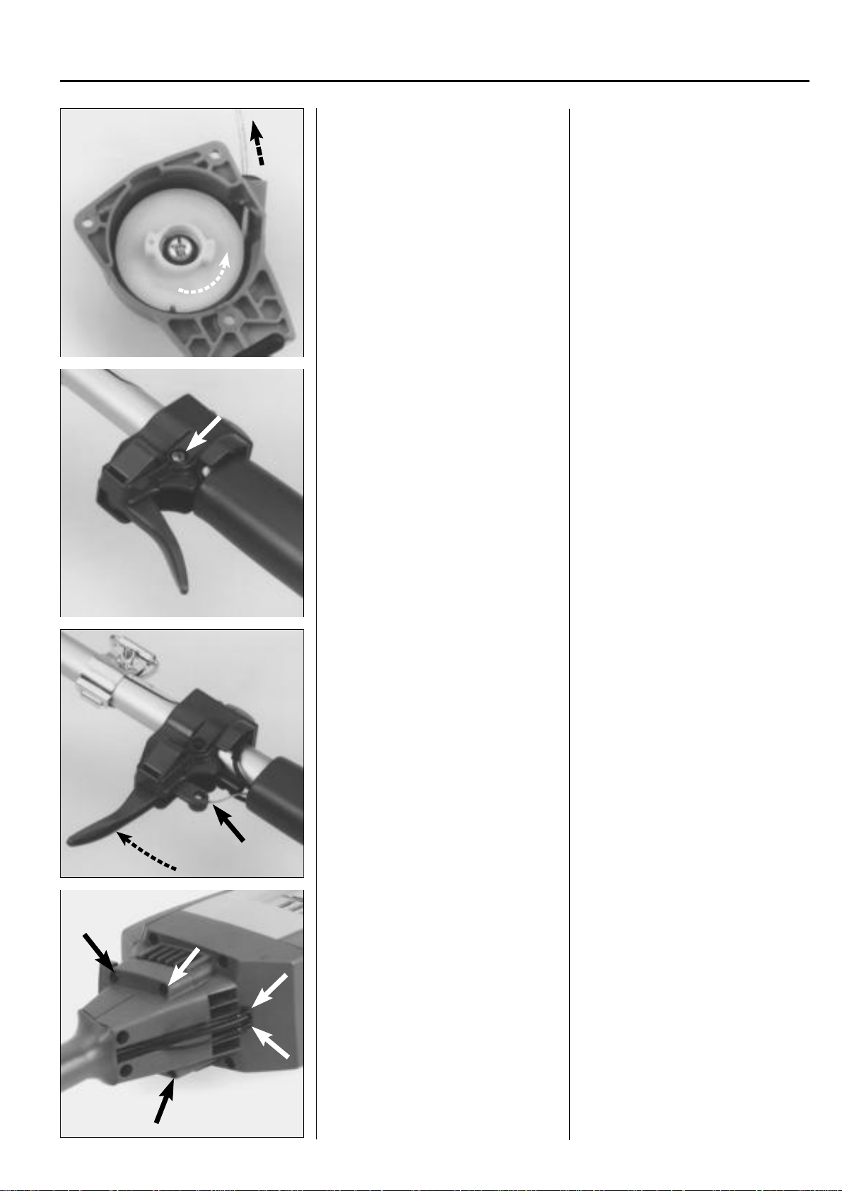
Release the spring pressure.
Remove the screw and washer in the
centre of the starter pulley and bearing
sleeve.
Lift out the starter pulley.
Model 265
Dismantling
Release the spring pressure. Pull out the
starter cord approx. 30 cm.
Hold the starter pulley with your thumb
and place the cord in the cut-out on the
starter pulley rim.
Let the starter pulley slowly recoil.
NOTE!
Stop the spring with your thumb.
WARNING!
!
Take care not to injure your thumb
on the screw at the cord's fastening.
Remove the screw and washer in the
centre of the starter pulley and bearing
sleeve.
Lift out the starter pulley carefully so that
the spring does not follow and fly out.
!
WARNING!
Wear protective glasses. The return
spring can fly out and cause personal injury.
4
www.mymowerparts.com
For Husqvarna Parts Call 606-678-9623 or 606-561-4983
Starter
Remove the spring from the starter housing.
Assembly
Insert a new spring in the starter housing.
1
Remove the spring from the starter housing by knocking it against a bench with the
spring facing downwards.
!
WARNING!
Wear protective glasses.
Assembly
Fit a new return spring if necessary.
Let the spring retainer ring remain in
place.
1. Place the spring over its seating in the
starter housing
2. Push the spring into its right position
using your thumb and let the retainer
ring slide off the spring.
3. Lubricate the spring with a few drops
of oil.
NOTE!
Do not forget the Pertinax disc between
the spring and starter housing.
!
WARNING!
Wear protective glasses.
B
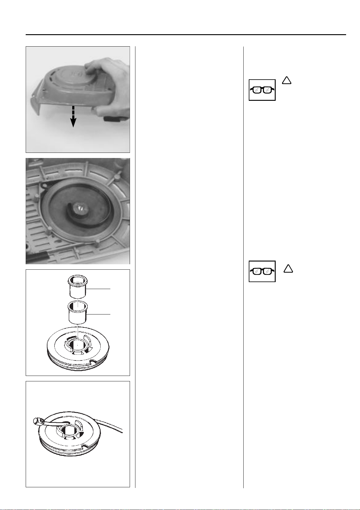
Check the starter pulley's bearing.
A
If necessary replace the sleeves (A) and
(B).
If necessary replace the starter cord.
Check the starter pulley's bearing. If it is
heavily worn the bearing sleeve (A) can
be replaced.
Cut out the sleeve and press in a new
sleeve.
If there is still too much play on the bearing a new metal sleeve (B) should also be
fitted.
If necessary replace the starter cord. Use
Husqvarna original pre-cut cord or cord
cut to the same length from a reel.
Thread the new cord through the hole in
the starter pulley as shown in the illustration and screw the plastic cube on the end
of the cord. Let it protrude approx. 3 mm
and melt it using a soldering iron to ensure a secure fastening is obtained.
www.mymowerparts.com
Tip!
The knot on the starter cord in the handle
can be difficult to undo. It is easier if you
place the knot on a hard surface and hit it
with a hammer.
5

For Husqvarna Parts Call 606-678-9623 or 606-561-4983
1
Starter
Wind the cord around the starter pulley
about 3 turns
pulley in the starter housing.
Fit the washer and screw that hold the
starter pulley.
B
clockwise
and position the
Wind the cord around the starter pulley
about 3 turns
pulley in the starter housing.
Check that the return spring grips the
starter pulley hub correctly.
Lubricate the bearing sleeve (B) with a
few drops of oil and insert the starter
pulley.
Fit the washer and screw.
Use Loctite on the screw.
clockwise
and position the
Fit the starter handle on the cord.
Tension the return spring.
Insert the cord through the cord guide in
the starter housing and anchor it in the
starter handle by tying a knot.
Fold down the free ends and pull the knot
fully into the starter handle.
To tension the return spring pull out the
starter cord fully and lift it into the cut-out
in the starter pulley.
Hold the pulley using your thumb then
tension the spring by turning the starter
pulley
clockwise
approx. 2 turns.
6
www.mymowerparts.com
For Husqvarna Parts Call 606-678-9623 or 606-561-4983
Max
+ 1/2 r
Starter
Check the spring tension.
Model 250
Dismantling
Release the spring tension.
Remove the starter pulley.
1
Check the spring tension.
It should be possible to turn the starter
at least a further half turn
pulley
starter cord fully extended
Model 250
Dismantling
Release the spring tension in the same
way as described for model 265.
Remove the screw in the centre of the
starter pulley and lift out the pulley.
with the
.
Carefully remove the spring cassette so
that the spring does not fly out.
Check the starter pulley and starter housing for wear and damage.
Remove the screws and lift out the spring
cassette.
!
WARNING!
Wear protective glasses.
Despite the spring sitting in a cassette it
can still fly out when the cassette is pried
from the guide pin when inserting the
cord in the starter housing.
Check the following:
1. Wear on the drive pins on the starter
pulley.
If necessary replace the starter cord
as for 265RX and cord spec.
2. Nut in the nut pocket is in position and
the thread is undamaged.
3. Cord entry in the starter housing. If
worn the housing should be replaced.
www.mymowerparts.com
7

For Husqvarna Parts Call 606-678-9623 or 606-561-4983
1
Starter
Assembly
Fit a new spring cassette if necessary.
Fit the spring cassette in the starter housing.
Assembly
Lubricate the return spring with a few
drops of oil or a cold resistant grease.
Ensure the spring has been pressed down
to the bottom of the cassette especially at
the fastening points.
Press the spring cassette into the starter
housing and tighten the screws.
Check that the end of the spring is approx.
3 mm from the spindle to help assembly
of the starter pulley.
Lubricate the surface of the cassette with
oil or cold resistant grease.
Fit a new starter cord.
Fit the starter pulley.
Fit a new starter cord.
Tie a small knot on the cord and melt the
ends of the cord so that is does not fray .
Wind the cord approx. 3 turns
on the starter pulley.
wise
Tip!
First thread the cord straight through the
hole in the starter pulley and then back
again and out through the slot.
Lubricate the spindle in the starter housing with a few drops of oil and position the
starter pulley and tighten the screw.
Fit the starter handle as described for
model 265, but tie a double knot as the
cord is lighter.
anticlock-
8
www.mymowerparts.com

For Husqvarna Parts Call 606-678-9623 or 606-561-4983
Max
Starter
Tension the return spring.
Check the spring tension.
1
To tension the return spring.
Wind the cord 2 turns
around the hub on the starter pulley and
pull out the starter handle until the cord is
extended.
Repeat the procedure once more.
NOTE!
With the starter cord fully extended it must
still be possible to turn the starter pulley
least a further half turn
anticlockwise
.
at
+ 1/2 r
Models 240/245
Dismantling
Release the spring.
Remove the starter pulley.
Lift out the spring cassette.
Models 240/245
Dismantling
Release the spring tension as described
for model 265.
Remove the screw and washer and lift out
the starter pulley.
!
WARNING!
Wear protective glasses.
The spring cassette sits freely in the starter
housing and can easily be lifted out to be
replaced.
www.mymowerparts.com
9

For Husqvarna Parts Call 606-678-9623 or 606-561-4983
1
Starter
Assembly
Check the starter housing for wear and
damage.
Fit the spring cassette.
Anchor the starter cord in the starter
pulley and wind it approx. 4 turns
wise
onto the pulley .
clock-
Assembly
Check the cord guide in the housing. If it
is worn the starter housing must be replaced.
Lubricate the spring with a few drops of oil
and position the spring cassette in the
starter housing.
Tie a small knot on the cord and seal the
ends by melting the cord ends, e.g. with a
soldering iron.
Anchor the starter cord in the starter
pulley and wind it about 4 turns
around the pulley.
Lubricate the bearing spindle with a few
drops of oil and fit the starter pulley in the
starter housing.
clockwise
Fit the starter pulley in the starter housing.
Fit the starter handle on the cord.
Position the washer and tighten the screw.
Fit the starter handle as described for
model 265, but tie a double knot as the
cord is lighter.
10
www.mymowerparts.com

For Husqvarna Parts Call 606-678-9623 or 606-561-4983
Max
Starter
Tension the return spring.
Check the spring tension.
1
To tension the return spring
Wind the cord 2 turns clockwise around
hub on the starter pulley and pull out
the
the starter handle until the cord is fully
extended.
Repeat the procedure once more, but
only wind the cord 1 turn around the hub.
Check the spring tension.
NOTE!
With the starter cord fully extended it
must still be possible to turn the starter
pulley
at least a further half turn.
+ 1/2 r
Models 225, 232, 235, 240
Dismantling
Release the spring tension and dismantle the starter pulley.
Remove the spring cassette.
Models 225, 232, 235, 240
Dismantling
Release the spring tension as described
for model 265.
Remove the screw and washer and lift out
the starter pulley.
Remove the screw and lift out the spring
cassette from the starter housing.
!
WARNING!
Wear protective glasses.
www.mymowerparts.com
11

For Husqvarna Parts Call 606-678-9623 or 606-561-4983
1
Starter
Assembly
Check the starter housing for wear and
damage.
Fit a new spring cassette if necessary.
Fit a new starter cord. Specs as before.
Assembly
Check the cord entry.
If it is worn the starter housing must be
replaced.
Lubricate the return spring with a few
drops of oil and fit the cassette in the
starter housing.
NOTE!
The end of the spring should be 3–4 mm
from the spindle to help assembly of the
starter pulley.
Fit a new starter cord. Tie the smallest
knot possible on the cord and melt the
ends to stop it from fraying.
Wind the cord about 3 turns
on the starter pulley.
Position the starter pulley in the starter
housing and fit the washer and screw.
anticlockwise
Max
Fit the starter handle.
Tension the return spring.
Check the spring tension.
Fit the starter handle as described for
model 265.
Tension the return spring by winding the
starter cord 2 turns anticlockwise around
the
hub on the starter pulley.
Repeat the procedure once more, but
with the cord only wound once around the
hub.
NOTE!
With the starter cord fully extended it
must still be possible to turn the starter
pulley
at least a further half turn.
12
+ 1/2 r
www.mymowerparts.com
For Husqvarna Parts Call 606-678-9623 or 606-561-4983
Starter
Model 122
2
1
Dismantling
Remove the covers from the muffler and
cylinder.
Dismantle the starter from the engine
body.
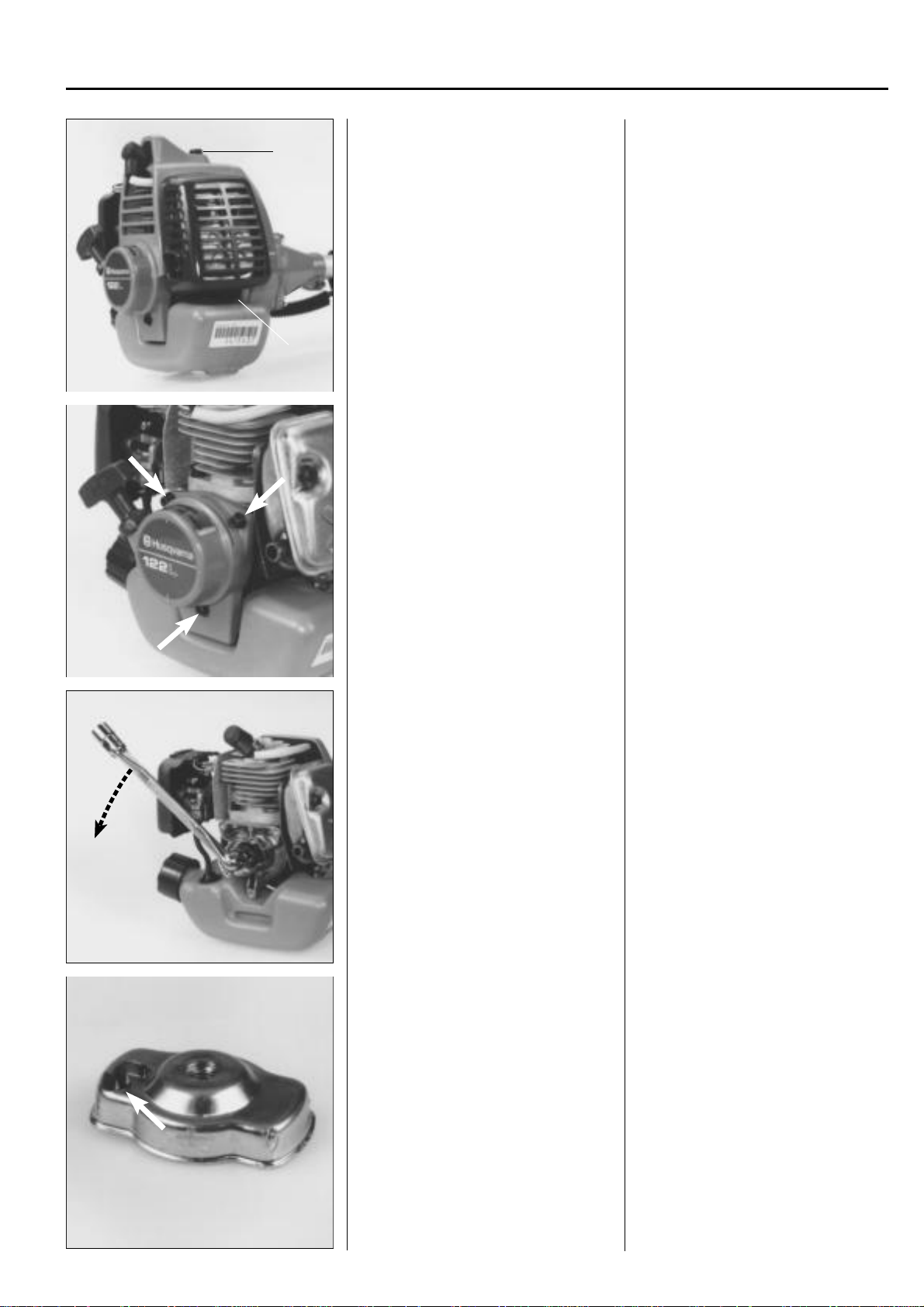
Model 122
Dismantling
Y ou must first remove the covers over the
muffler and cylinder to be able to dismantle the starter.
Remove the screw (1), pull out the lower
edge of the cover and lift it off.
Remove the screw (2) and lift off the
cylinder cover.
Remove the screws and lift off the starter
from the engine body.
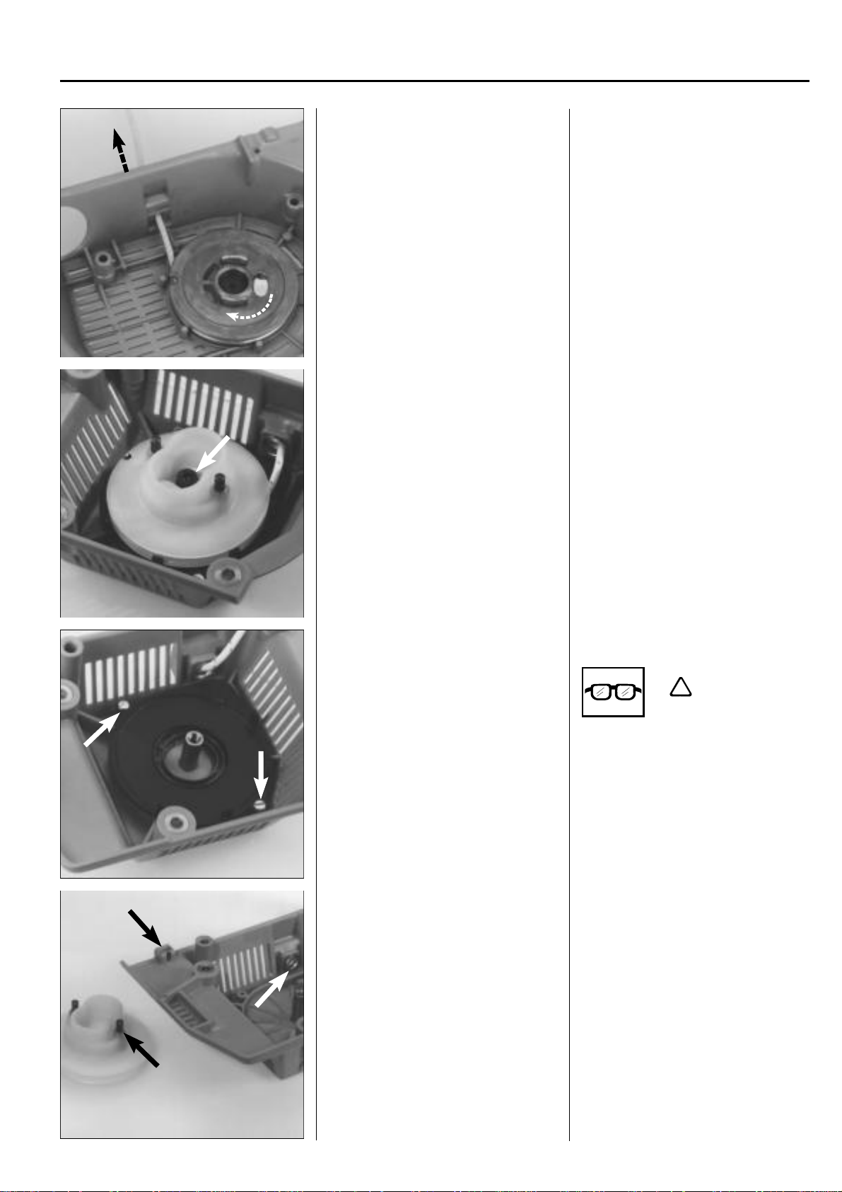
1
Remove the starter hub from the crankshaft.
Replace the drive dog if it is damaged or
worn.
Unscrew the hub from the crankshaft.
Use a hammer and punch to loosen the
hub if necessary.
NOTE!
The nut is brazed on the drive.
The drive dog and its spring can easily be
replaced if damaged or worn.
Squeeze together the drive dog's axle
stud with pliers when dismantling.
www.mymowerparts.com
13

!
For Husqvarna Parts Call 606-678-9623 or 606-561-4983
1
Starter
Release the spring tension and dismantle starter pulley.
Assembly
Fit a new return spring in the starter unit.
Release the spring tension as described
for model 265.
Remove the screw and washer and carefully lift out the starter pulley so that the
return spring does not fly out.
!
WARNING!
Wear protective glasses.
Assembly
Fit a new return spring in the starter unit.
Press the spring down correctly on the
fastener and lubricate with a few drops of
oil or cold resistant grease.
Ensure the ends of the spring are 2-3 mm
from the spindle.
Fit a new starter cord and position the
starter pulley in the starter housing. Cord
specs as before
Fit the starter handle.
Tension the return spring.
WARNING!
Wear protective glasses.
Fit a new starter cord. Tie the smallest
knot possible on the cord but leave free
an end of approx. 10 mm.
Press the free end into the cut-out in the
pulley hub reinforcement.
Wind the cord about 4 turns
(seen from the rear) on to starter pulley.
Position the starter pulley in the starter
housing and fit the washer and screw.
Fit the starter handle as described for
model 265, but tie a double knot on the
cord.
Lift up the starter cord from the cut-out
and wind it 2 turns
the
hub on the starter pulley . Pull out the
starter handle until the cord is fully extended.
Repeat the procedure once again.
anticlockwise
clockwise
around
14
www.mymowerparts.com
For Husqvarna Parts Call 606-678-9623 or 606-561-4983
+ 1/2 r
Max
Starter
Check the spring tension.
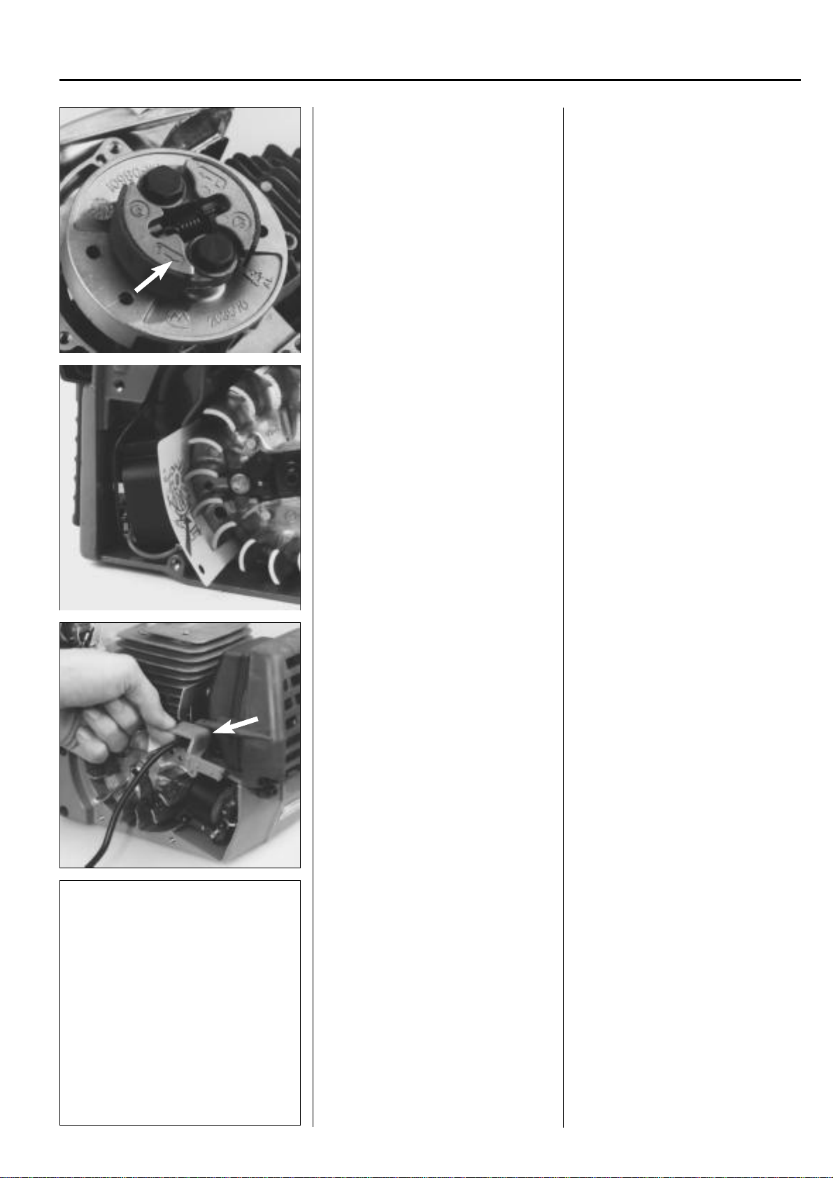
Models 32, Mondo
Dismantling
Remove the screws that hold the throttle
trigger.
1
NOTE!
With the starter cord fully extended it
must still be possible to turn the starter
pulley
at least a further half turn.
Fit the hub, starter and covers in the
reverse order set out for dismantling.
Models 32, Mondo
Dismantling
Remove the screws that hold the throttle
trigger and slide it along the shaft as far as
the throttle cable and electrical cables will
allow.
Lift out the throttle cable.
Disconnect the electrical cables.
Remove the shaft complete with handles.
Move the throttle trigger forward and lift
the throttle cable out of the trigger.
Disconnect the electrical cables from the
engine body, remove the 4 screws that
hold the shaft and handles on the starter
housing.
Lift off the shaft.
www.mymowerparts.com
15
For Husqvarna Parts Call 606-678-9623 or 606-561-4983
1
Starter
Dismantle the centrifugal clutch
Dismantle the starter.
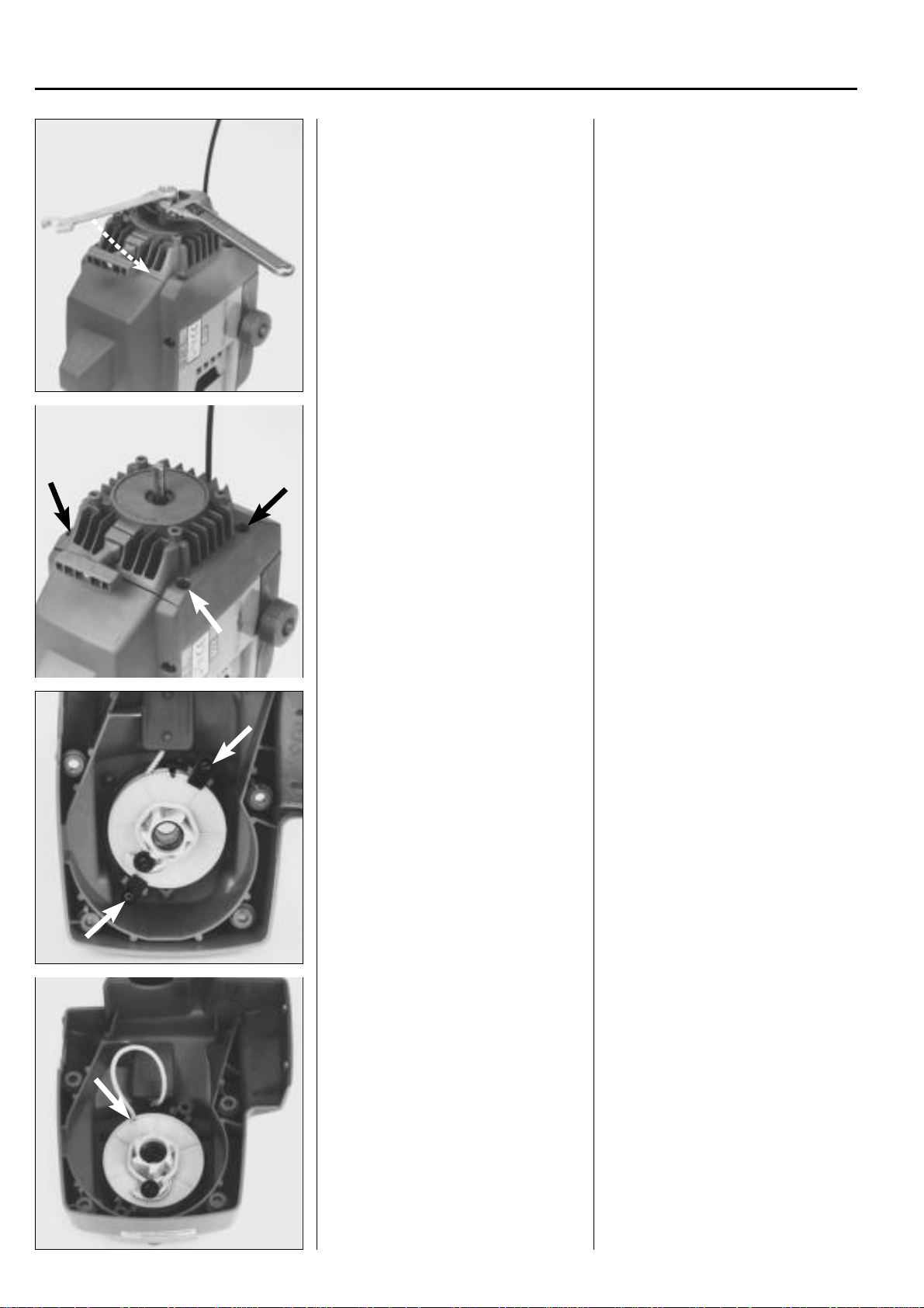
Undo the nuts holding the centrifugal
clutch and lift off the clutch and the large
washer.
Remove the 4 screws and lift off the
starter.
Model Mondo
Also remove the screw by the spark plug.
Model 32
Pull out the electrical cables from the starter
housing using a pair of pliers.
Remove the two locking plates that hold
the starter pulley axially.
Release the spring tension.
Remove the two locking plates that hold
the starter pulley axially.
Release the spring tension.
Pull out the starter cord about 30 cm and
place the cord in the cut-out on the edge
of the starter pulley
16
www.mymowerparts.com
!
For Husqvarna Parts Call 606-678-9623 or 606-561-4983
Starter
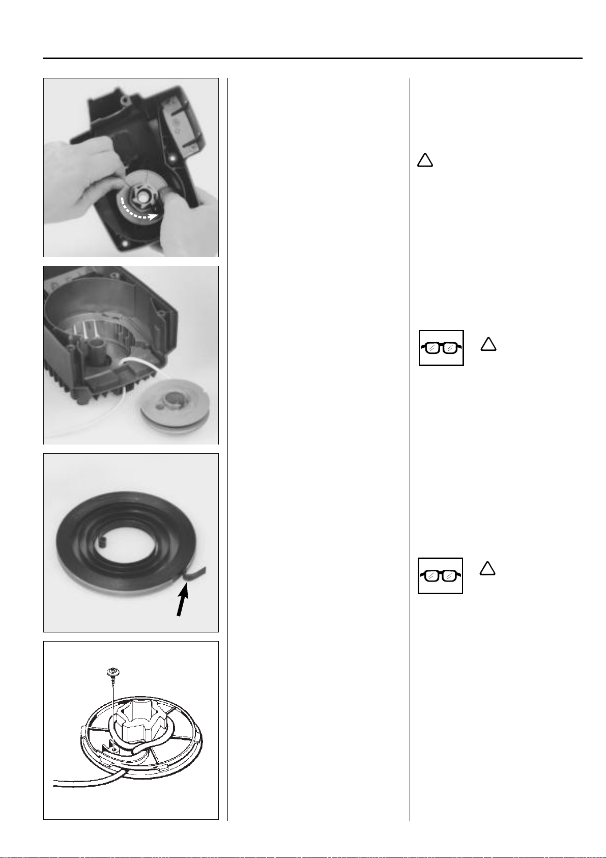
Let the starter pulley slowly rotate backwards.
Lift off the starter pulley.
Remove the return spring from the starter
housing.
1
Let the starter pulley slowly rotate backwards (anticlockwise) and then lift off the
pulley.
NOTE!
Stop the rotation using your thumb.
WARNING!
Take care so that your thumb is not
injured by the cord's fastening screw.
Exercise great care when removing the
starter spring.
The spring is tensioned inside a sheet
cassette, nevertheless it can still easily fly
out when dismantled.
Assembly
Insert a new spring cassette in position in
the starter housing.
!
WARNING!
Wear protective glasses.
Assembly
Lubricate the return spring with a few
drops of oil and position the new spring
cassette in the starter housing.
If the spring, despite your being careful,
has flown out reposition it again in the
cassette with the end turned as shown in
the picture.
!
WARNING!
Wear protective glasses.
Replace the starter cord and attach it as
shown in the diagram.
www.mymowerparts.com
Attach the new starter cord to the starter
pulley and wind it about 3 turns
around the pulley.
clockwise
17

For Husqvarna Parts Call 606-678-9623 or 606-561-4983
1
Starter
Fit the starter pulley.
Fit the starter handle.
Lubricate the pulley spindle with a few
drops of oil.
Ensure the end of the spring is about 2–
3 mm from the spindle and position the
starter pulley.
NOTE!
Do
not
tighten the locking plates that hold
the starter pulley axially.
Fit the starter handle as described for
model 265.
Tie a double knot on Mondo model.
Max
+1/2 r
Tension the return spring.
Repeat the spring tensioning and fit the
locking plates.
Tension the return spring.
● Pull out the cord approx. 30 cm and
stop the starter pulley with your thumb.
● Lift the cord up from one of the cut-
outs on the starter pulley.
● Wind the cord 2 turns
around the hub on the starter pulley.
● Pull out the starter cord fully.
Repeat the spring tensioning once more.
Ensure the starter pulley can still be turned
at least a further half turn
fully extended.
Tighten the locking plates that hold the
starter pulley axially.
NOTE!
Model 32 has a thin spacer under the
plates.
clockwise
with the cord
18
www.mymowerparts.com

For Husqvarna Parts Call 606-678-9623 or 606-561-4983
Starter
Assembly , general
Assemble the starter following the reverse order set out for dismantling.
503 21 22-01
Replacing the drive dogs
See chapter 2 "Ignition system, flywheel".
1
Assembly , general
Assemble the starter.
Pull out the starter cord a little. Position
the starter. Release the starter cord and
ensure that the drive dogs grip in the
starter pulley.
Tighten the screws.
NOTE!
If the plastic threads in the crankcase
have, for some reason, been damaged it
is recommended to use an over dimensioned screw (no 503 21 22-01).
Replacing the drive dogs.
See chapter 2 "Ignition system, flywheel".
www.mymowerparts.com
19

For Husqvarna Parts Call 606-678-9623 or 606-561-4983
20
www.mymowerparts.com

For Husqvarna Parts Call 606-678-9623 or 606-561-4983
Ignition system
2.
Contents
Checking the spark 22
Replacing the spark plug cover 24
Dismantling 25
Drive dogs 27
Assembly 28
www.mymowerparts.com
21

For Husqvarna Parts Call 606-678-9623 or 606-561-4983
2
Ignition system
The engine is equipped with an electronic ignition
system with no moving parts. Consequently, a faulty
component cannot be repaired, but must be replaced
with a new one.
Checking the spark
Clean the electrodes and check the electrode gap.
The ignition spark in an electronic ignition system has a very short burn time and can be
judged to be weak and is at times difficult to see
when trouble shooting.
Checking the spark
Remove the spark plug and clean off any
carbon deposits using a wire brush.
Check the electrode gap, it should be 0.5
mm.
Adjust the gap to the correct size using
the side electrode.
If the electrodes are worn by more than
50% the spark plug should be replaced.
Check whether there is a spark when
attempting to start, if not test using spark
plug no. 502 71 13-01.
If the electrodes are worn by more than
50% the spark plug should be replaced.
An excessive spark gap can overload the
ignition module and risk short circuiting.
Ensure the stop switch is in the 'start'
position.
Earth the spark plug against the cylinder
and pull the starter handle sharply.
There should now be a spark between the
electrodes.
If there is no spark try using the test spark
plug no. 502 71 13-01.
If there is spark now the spark plug is
faulty.
Fit a new spark plug.
22
502 71 13-01
www.mymowerparts.com
For Husqvarna Parts Call 606-678-9623 or 606-561-4983
Ignition system
Fit a new spark plug.
If there is no spark disconnect the stop
switch.
Replace the switch if necessary.
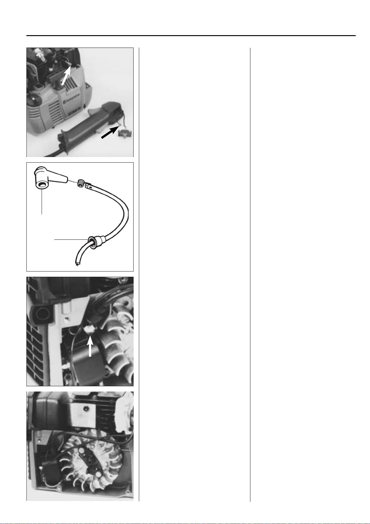
Check the ignition lead's connections.
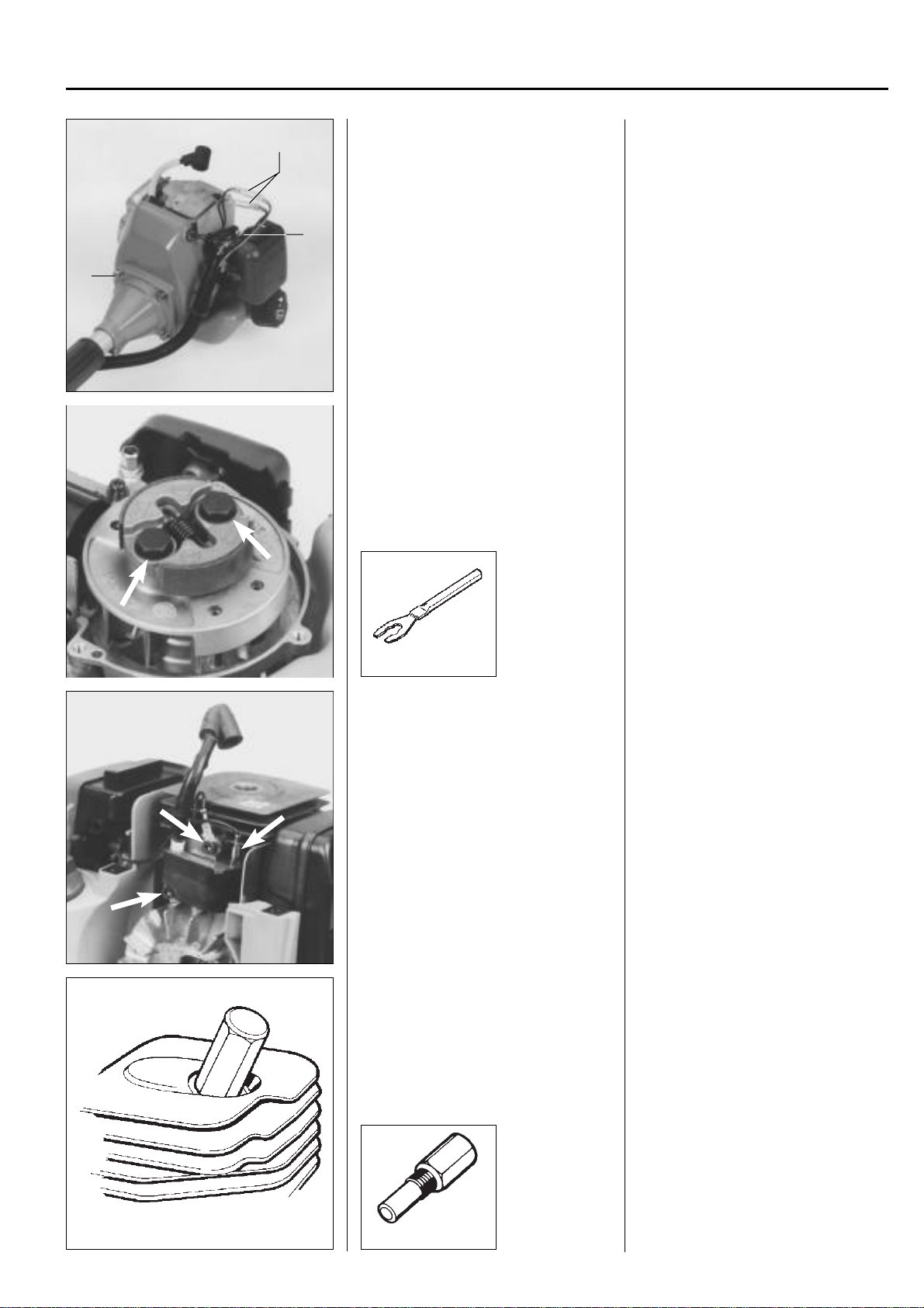
A
Fit a new spark plug.
If the procedure does not produce a spark
remove the short circuit cable from either
the ignition module or the stop switch.
If there is now a spark the stop switch is
faulty.
Replace the switch.
Still no spark?
Check the spark plug connections.
Pull back the rubber covers by the spark
plug (A) and the ignition module (B) and
check that the ignition cable is not damaged. Cut off a piece of the cable to give
a good connection if required.
2
B
Lubricate the cable ends with grease.
Check other cables and connections.
Lubricate the cable ends with a little grease
to facilitate assembly and to prevent dampness from entering the connections.
Still no spark?
Check other cables and connections for
bad contact (dirt corrosion, cable breaks
and damaged insulation).
www.mymowerparts.com
Tip!
Use an ohmmeter to check whether there
is a broken cable caused by crushing, for
example.
23

For Husqvarna Parts Call 606-678-9623 or 606-561-4983
2
Ignition system
Check the air gap.
502 51 34-02
Adjust the air gap.
Still no spark?
Check the air gap between the flywheel's
magnet and the ignition module. The gap
should be 0.3 mm.
Use air gap gauge 502 51 34-02.
Model 122 should have a 0.38 mm gap.
Use air gap gauge 531 00 48-61
531 00 48-61 Mod. 122
Adjust the air gap to the right measurement.
● Loosen the screws.
● Insert the gauge and press the igni-
tion module against the flywheel.
● Tighten the screws and check the air
gap once again.
If there is still no spark the ignition system
should be replaced.
Changing the spark plug
cover
1. Push the ignition cable through the
spark plug cover.
2. Make a hole in the ignition cable for
the contact spiral.
502 50 06-01
3. Fit the contact spiral on the ignition
cable.
Changing the spark plug
cover
1. Lubricate the ignition cable using a
little grease and push it through the
spark plug cover.
2. Cut off a piece of the ignition cable
(about 5 mm) and make a hole in the
cable for the contact spiral using the
pliers no. 502 50 06-01.
3. Fit the contact spiral on the ignition
cable, taking care to form the wire
along the cable.
4. Pull the contact spiral into the spark
plug cover.
NOTE!
It is important that the point of the contact
spiral is positioned so that it's unable to
pierce the spark plug cover.
24
www.mymowerparts.com
For Husqvarna Parts Call 606-678-9623 or 606-561-4983
Ignition system
A
B
C
General
Remove all components necessary to
gain access to the flywheel and ignition
module.
Dismantle the fan cover and the centrifugal clutch.
531 00 48-62
Dismantling
Dismantling
General
Remove the cylinder cover, spark plug,
starter and air pipe support.
Model 32. Model Mondo
Remove the starter. See chap. 1 "Starter ."
Model 122
Pull apart the connector on the electrical
cables (A) and remove the throttle cable
from the carburettor lever (B).
Remove the screws (C) and lift off the
shaft.
Remove the screws and lift off the fan
cover.
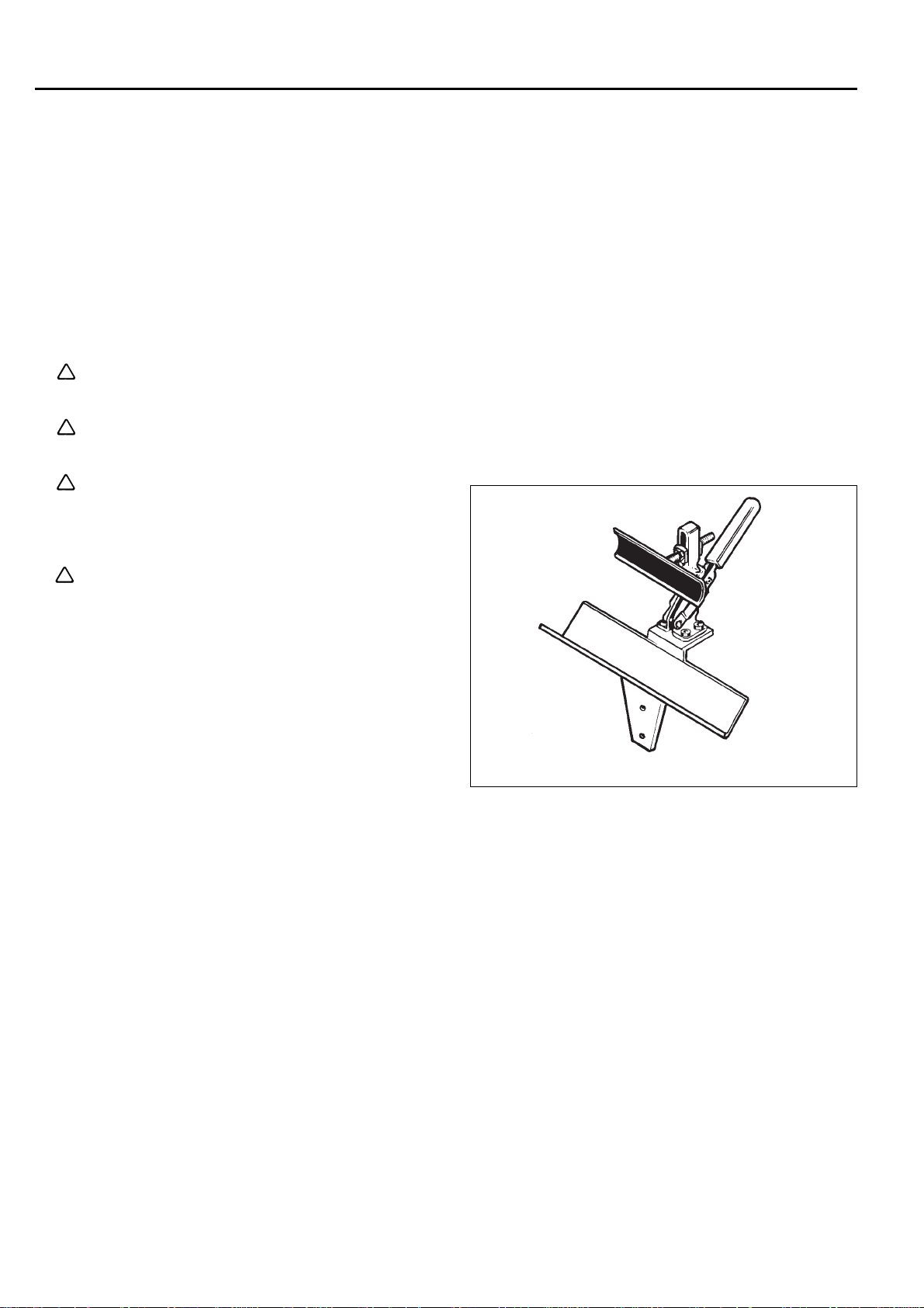
Dismantle the centrifugal clutch by loosening the two bolts.
NOTE!
Hold the clutch carefully using a pipe grip
so that the soft clutch linings are not
damaged.
We recommend the use of tool no.
531 00 48-62.
Notice which way the clutch faces. The
"L"-markings on the clutch shoes face
outwards.
2
Dismantle the ignition module and loosen
other cable connections.
Fit the piston stop, no. 504 91 06-05 in the
spark plug hole.
Dismantle the ignition module by unscrewing the two bolts.
Loosen the other cable connections and
lift out the ignition module.
Fit the piston stop, no. 504 91 06-05 in the
spark plug hole.
Make sure the piston stop is screwed in
fully.
Carefully bring the piston into contact
with the stop before applying pressure on
the flywheel nut.
NOTE!
The piston stop cannot be used on model
122.
504 91 06-05
www.mymowerparts.com
25
For Husqvarna Parts Call 606-678-9623 or 606-561-4983
2
Ignition system
Model 240/245
Undo the flywheel nuts and the drive
pawls.
Dismantle the flywheel.
Model 265
Use the flywheel puller 502 51 49-01.
Model 240/245
Undo the flywheel nuts and the drive
pawls.
Remove the flywheel from the crankshaft.
Model 265
Fit the flywheel puller 502 51 49-01 on the
flywheel. Select suitable bolts and position the puller so that it pulls straight.
26
502 51 49-01
Model 240/245
Pull off the flywheel using the bearing
puller.
504 90 90-01
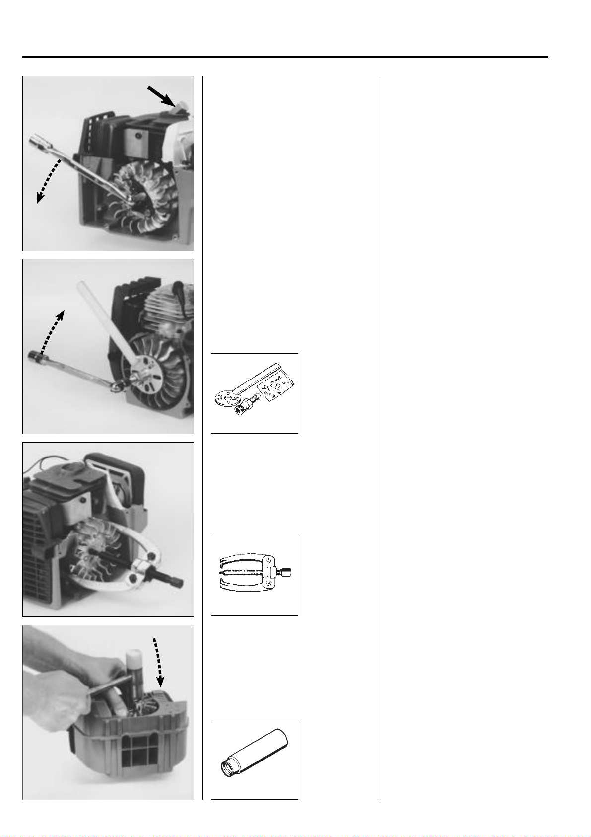
Model 225/232/235
Dismantle the flywheel by knocking with a
hammer.
502 51 94-01
Model 240/245
Pull off the flywheel using the bearing
puller no. 504 90 90-01.
NOTE!
The arms on the puller should be placed
by and opposite the magnet on the flywheel to avoid damaging it.
Is the flywheel really tight?
Lift up the engine body by holding the
puller and knock the puller screw a few
times with a hammer.
Model 225/232/235
Screw the nut on the axle to protect the
thread.
Unhook the springs and fold back the drive
dogs to give a little room for the hammer.
Grip the flywheel and lift up the engine
body.
Apply a few sharp blows with a hammer on
the flywheel nut until the flywheel frees
itself from the axel.
Tip!
Use the push bar to protect the tread at the
same time as it is easier to use the
hammer.
Do not screw the push bar completely up
to the flywheel – leave about 2 mm.
www.mymowerparts.com
For Husqvarna Parts Call 606-678-9623 or 606-561-4983
Ignition system
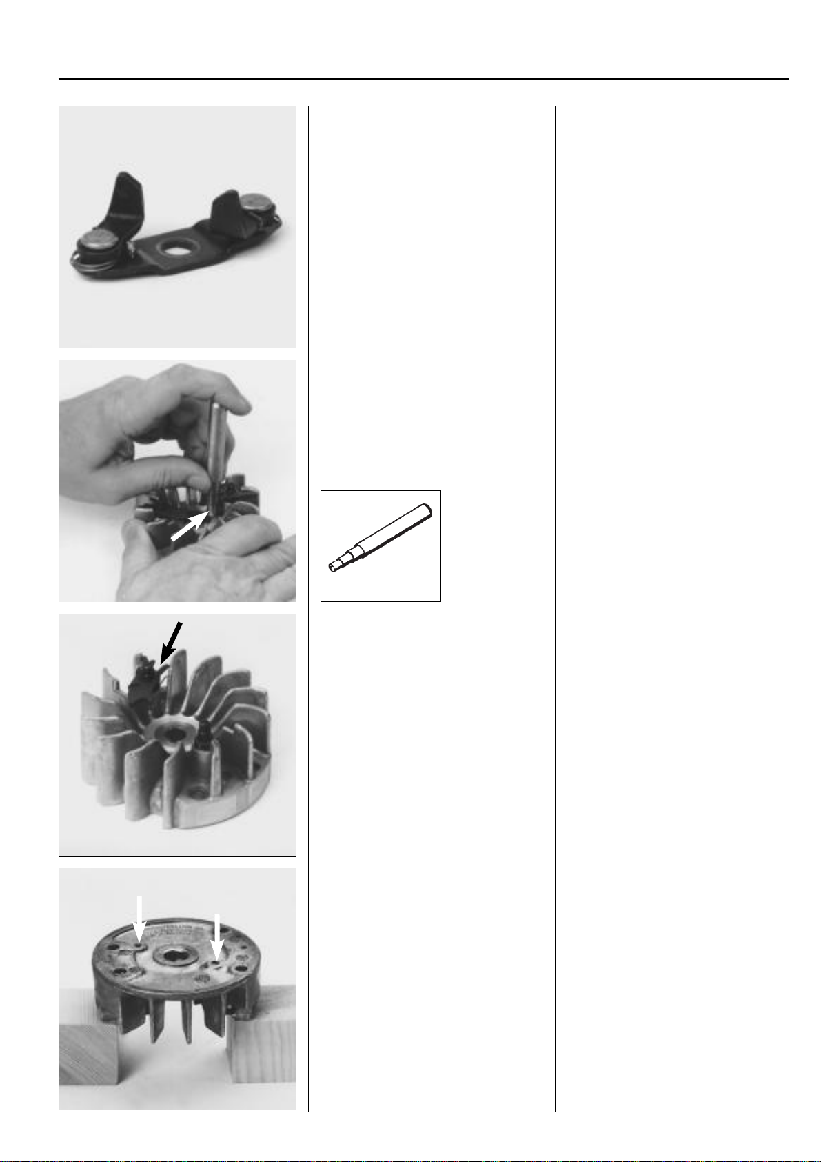
Drive pawls
Check the drive pawls with regard to wear
and cracking.
Replace damaged components.
Dismantle the locking clip. Turn the locking clip so that the opening
Drive pawls
Check the drive pawls with regard to wear
and cracking.
Replace damaged components.
The entire unit must replaced if the drive
dogs are fitted on a separate bridge.
aligns with the centre of the flywheel.
Use, e.g. punch no. 505 38 17-05 and
press off the clip.
2
505 38 17-05
Dismantle the drive pawls and the return
spring.
Unscrew the bearing pin.
Replace any damaged parts.
Press out the bearing studs using a suitable punch.
Dismantle the drive pawls and the return
spring.
Unscrew the bearing pin.
Replace any damaged parts.
Check that the drive pawls move easily.
NOTE!
The spring clip's opening should be turned
outwards between the fan fins.
Replace the drive pawls and springs as
follows if they are journalled on a stud
pressed into the flywheel:
Place the flywheel on support blocks and
press out the studs using a suitable punch.
www.mymowerparts.com
27
For Husqvarna Parts Call 606-678-9623 or 606-561-4983
2
Ignition system
Replace damaged parts. Replace damaged parts.
Ensure the springs are not crushed when
the stud is pressed into the flywheel.
Check that the drive pawls move easily.
Model Mondo
The drive pawls can be dismantled once
the screws on the opposite side of the
flywheel have been removed.
Model Mondo
On these models the drive pawls are held
in place by screws, tightened from the
opposite side of the flywheel.
Dismantle the bolts and lift off the drive
pawls.
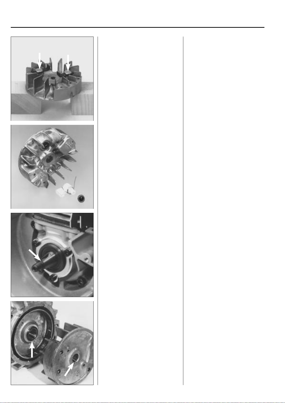
Assembly
Check that the keyway and key on the
crankshaft are not damaged.
Check that the keyway and cast key on
the flywheel are not damaged.
Fit the flywheel.
Assembly
Check that the keyway and key on the
crankshaft are not damaged.
Fit a new key if necessary and ensure it
sits correctly in the keyway .
NOTE!
If the crankshaft has two keyways it is the
keyway that is open all the way out to the
thread which is used if the flywheel has a
cast key.
Check that the keyway and cast key on
the flywheel are not damaged.
Fit the flywheel on the crankshaft and
check that key and keyway are correctly
aligned before the flywheel nut is tightened.
Tighten the nut to a torque of 25–35 Nm.
28
www.mymowerparts.com
For Husqvarna Parts Call 606-678-9623 or 606-561-4983
Ignition system
Model 122
Turn the centrifugal clutch so that the "Lmarking on the clutch shoes is facing
outwards.
Fit the ignition module.
Adjust the air gap (0.3 mm).
Fit the other cables.
Fit the remaining components in the re-
verse order set out for dismantling.
2
Model 122
As the centrifugal clutch is fitted on the
flywheel it is important that it is positioned
so that the "L-marking" on the shoes
outwards.
faces
"L" means left rotation.
Fit the ignition module.
Adjust the air gap (0.3 mm).
Also see page 24.
Fit the other cables and ensure they sit
correctly in the cable channels, etc. so
that they cannot be damaged.
Fit the remaining components in the reverse order set out for dismantling.
Model 250
Do not forget to fit the heat guard for the
ignition cable.
Model 250
Fit the earth cable using the AMP connector on the ignition module before it is
screwed onto the crankcase.
NOTE!
Do not forget the plastic components that
protect the ignition cable from the radiant
heat from the muffler.
www.mymowerparts.com
29
 Loading...