


For Husqvarna Parts Call 606-678-9623 or 606-561-4983
50, 50 Special, 51, and 55
Workshop Manual
531 03 00-76
www.mymowerparts.com

For Husqvarna Parts Call 606-678-9623 or 606-561-4983
This workshop manual is mainly intended for Husqvarna
50, 50 Special, 51, and 55 models, but certain chapters
can also be used for other models. The manual gives
information about how to repair the saw and how to use
special tools. In order to make sure that the saw will
function properly, always use Husqvarna original spare
parts and accessories.
The information, specifications and illustrations in this
manual are based on the information in effect at time of
printing. Any improvements or changes on these models
will be included in future manual revisions.
www.mymowerparts.com

For Husqvarna Parts Call 606-678-9623 or 606-561-4983
Page
2
3
4
5
6
7
Technical Specifications
Service Data
Service Tools
Safety Equipment
Rewind Starter
Ignition System
Centrifugal Clutch
2
3
3
4
12
15
22
8
9
10
12
13
Lubrication System, Oil Pump
Anti-Vibration System
Fuel System
Exhaust System
Cylinder & Piston
Crankcase & Crankshaft
26
30
32
47
46
51
www.mymowerparts.com

For Husqvarna Parts Call 606-678-9623 or 606-561-4983
Engine
Displacement - cc (cu. in.)
Bore - mm (in.)
Stroke - mm (in.)
Max. power of speed - rpm
Idling speed - rpm
Clutch engagement speed - rpm
No load free speed - rpm
Ignition system - Electroiux
Air gap - mm (in.)
Spark plug - Champion
NGK
Electrode gap - mm (in.)
49 (3.0)
44(1 .73)
32(1 .26)
8400
2500
3700
12500
ET
0.3 (0.012)
RCJ7Y
BPMR6A
0.5 (0.020)
51 (3.1)
45(1 .77)
32(1 .26)
8400
2500
3700
12500
ET
0.3 (0.012)
RCJ7Y
BPMR6A
0.5 (0.020)
51 (3.1)
45(1 .77)
32(1 .26)
9000
2500
3700
12500
ET
0.3 (0.012)
RCJ7Y
BPMR6A
0.5 (0.020)
53 (3.2)
46(1 .81 )
32(1 .26)
9000
2500
3700
12500
ET
0.3 (0.012)
RCJ7Y
BPMR6A
0.5 (0.020)
Fuel and Lubrication System
Carburetor - Walbro
Fuel tank volume - Iitre (pint)
Oil tank volume - Iitre (pint)
Oil pump capacity at 6000 rpm
cc/rein. 7.0 7.0
Oil pump type
WA82 WA82
0.6 (1 .27)
0.3 (0.63) 0.3 (0.63) 0.3 (0.63)
Automatic Automatic
Bar and Chain
Bar length
cm
inch
Chain pitch
Chain speed
.325 m/see
3/8 m/see.
Drive link gauge - mm (in.)
Weight - kg (Ibs)
Weight with 38 cm (15 in.)
guide bar and chain - kg (Ibs)
37-45
15-18
.325
17.417t
****
1.5 (0.058)
5.2 (1 1.5)
6.2 (13.7)
WT170
0.6 (1 .27) 0.6 (1 .27)
7.0 7.0
Automatic Automatic
37-45
15-18
.325
17.417t
****
1.5 (0.058)
5.2 (1 1.5)
6.2 (13.7)
37-49
15-20
.325 or 3/8
17.417t
20.2/7t
1.5 (0.058)
5.2 (1 1.2)
6.2 (13.7)
WTl 70
0.6 (1 .27)
0.3 (0.63)
37-49
15-20
.325 or 3/8
17.417t
20.2/7t
1.5 (0.058)
5.2 (1 1.2)
6.2 (1 3.7)
www.mymowerparts.com
For Husqvarna Parts Call 606-678-9623 or 606-561-4983
Service Data
& Service Tools
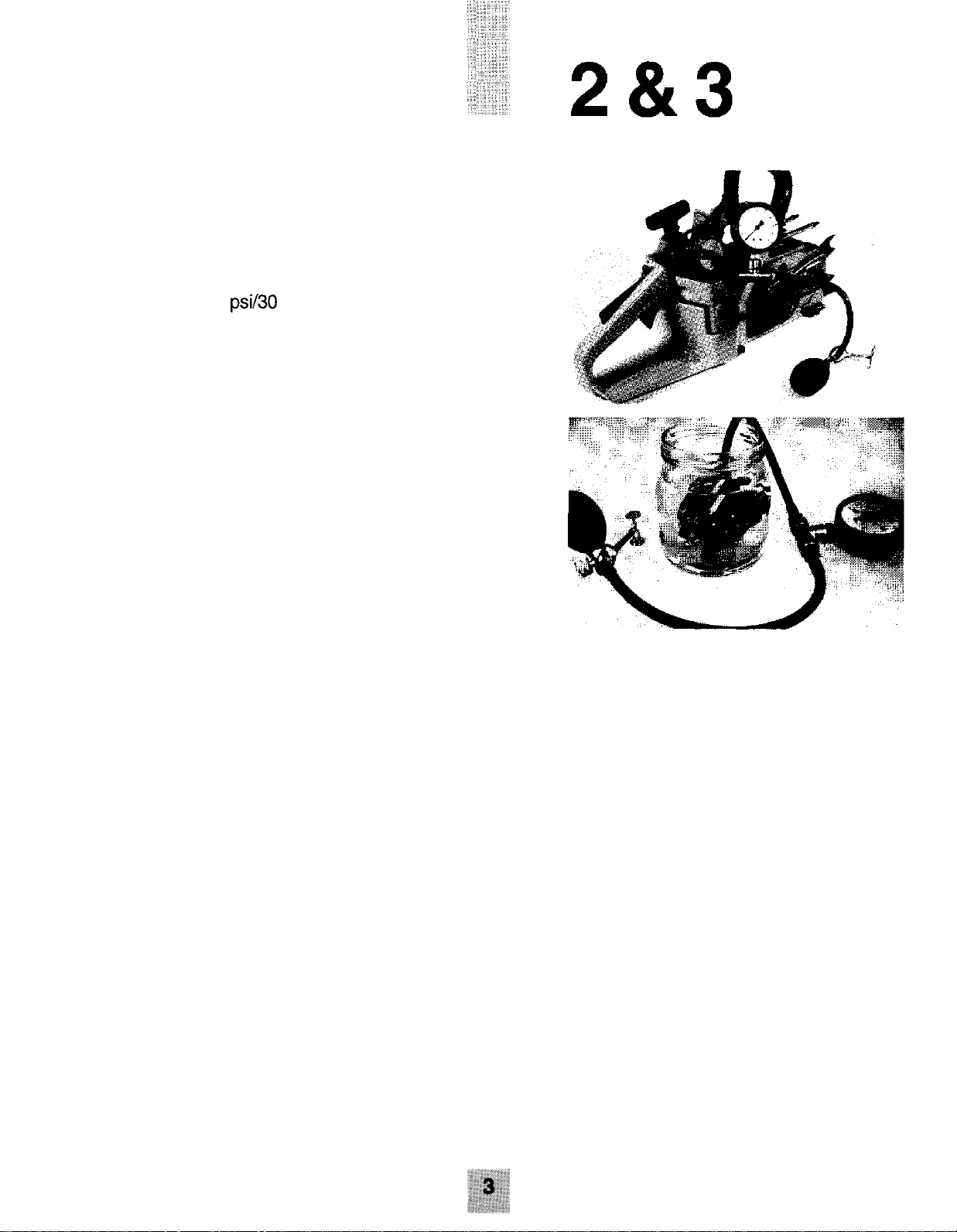
Service Data
Leakage Test
Crankcase/cylinder
Recommended pressure: 30 kPa (0.3 kp/cm2) (4 psi)
Maximum leakage: 20 kPa/30 sec. (0.2 kp/cm2)
(3
psi/30
see)
Service tools for test:
5025038-01
5049029-02
5025046-01
5025403-01
Pressure gauge
Intake/exhaust cover plate, 2 pieces
Sleeves, 2 pieces
Sleeves, 2 pieces
Leakage Test
Carburetor
Recommended pressure: 50 kPa (0.5 kp/cm2) (7.2 psi)
Maximum leakage: No leakage permitted
Service Tools
5025006-01
5025018-01
5025019-01
5025022-01
5025026-01
5025030-09
5025030-12
5025033-01
5025038-01
5025046-01
5025070-01
5025079-01
5025083-01
5025087-01
5025099-01
5025134-02
5025161-01
5025191-01
5025194-01
5027113-01
5027114-01
5049029-02
5049090-01
5052679-12
Assembling pliers, spark plug
Allen key, 4 mm
Allen key, 3 mm
Socket spanner, 8 mm
Puller, complete
Crankshaft installation device, Model 50 serial # 9250857 and up
Crankshaft installation device
Piston Stop
Pressure gauge
Sleeves, 2 pieces
Piston mounting set
Crankshaft seal installation tool
Hook for fuel filter
Allen screwdriver with ball
Worm wheel puller
Air gap gauge, ignition
Crankshaft removal tool
Air gap gauge, spark plug
Flywheel removal tool
Test plug
Tachometer
Intake/exhaust cover plates, 2 pieces
Puller, ball bearing
Flywheel removal tool, Model 50 serial # 9250857 and up
www.mymowerparts.com
For Husqvarna Parts Call 606-678-9623 or 606-561-4983
4
The chain brake system has a strong spring under
tension. This spring activates the chain brake band when
the chain brake is engaged. The spring is located under
a cover plate that must be removed during servicing.
Anytime the cover is removed and the spring is still under
tension it may dislodge without warning. Eye protection
must be worn during disassembly and reassembly of the
chain brake.
Chain Brake
Disassembly
Disengage chain brake. Remove clutch cover retaining
nuts and withdraw cover from the chain saw.
Clean chain brake and clutch cover assembly. Engage
the chain brake by moving the hand guard forward.
Remove hand guard retaining screw. Rethread screw
into pivot sleeve two turns. Press on screw head to drive
out pivot sleeve half on the opposite side.
www.mymowerparts.com

For Husqvarna Parts Call 606-678-9623 or 606-561-4983
Turn cover over. Using a suitable punch, drive out
remaining half of pivot sleeve. Separate hand guard from
cover.
Remove the five screws and lift off the cover plate.
CAUTION !
The spring is under tension.
Always wear safety goggles for eye protection.
Using the tip of a flat bladed screwdriver, carefully lift the
end of spring out of the cover.
Press out the pin which holds the linkage arm using a
suitable punch.
www.mymowerparts.com

For Husqvarna Parts Call 606-678-9623 or 606-561-4983
Turn the cover over and press out the brake bank
retaining pin with a punch.
Check the brake band for wear. Measure the thickness
of the band. The original thickness of the brake band is
0.80 mm (0.031 in.). The brake band must be exchanged
if the band is worn anywhere along its length to 0.65 mm
(0.026 in.) or less.
If the brake band needs to be exchanged, separate the
band from the linkage by removing the screw.
Assembly
Check all chain brake parts for wear or damage and
replace with new parts if necessary. Lubricate the linkage
and pivots with thin oil.
www.mymowerparts.com

For Husqvarna Parts Call 606-678-9623 or 606-561-4983
Assemble the brake band and knee link. Insert the roll
pin into the brake band so the open side of the pin is up
as shown in photo.
Insert the linkage and band assembly into the cover.
Secure the knee link to the cover with the retaining pin.
Slide the brake spring over the linkage spring post.
Using a flat bladed screwdriver, depress the spring, then
carefully press the spring end into the cover.
Install the cover plate.
www.mymowerparts.com

For Husqvarna Parts Call 606-678-9623 or 606-561-4983
Press the front hand guard into position. Install the pivot
sleeves and screw. Pull the hand guard back to
disengage the brake.
Mount the bar, chain and chain brake to the saw. Before
running the saw, check the brake function by moving the
hand guard forward until the brake engages. With the
brake engaged, it should not be possible to rotate the
saw chain around the guide bar. Pull the hand guard
back towards the front handle to disengage the brake.
Inertia Chain Brake Function
WARNING !
The engine must be stopped for the following test.
With the engine stopped, hold the chain saw with both
hands. With the chain saw horizontal, position the bar tip
approx. 35 cm (14 in.) above a tree stump or other firm
object such as a solid wood table.
www.mymowerparts.com

For Husqvarna Parts Call 606-678-9623 or 606-561-4983
While holding onto the rear handle, release your grip
around the front handle. The chain saw will swing downward allowing the bar tip to contact the tree stump. When
the tip of the bar contacts the stump, the chain brake
should activate.
Manual Chain Brake Function
Place the saw on firm ground and start the engine. Hold
the handles with both hands and apply full throttle.
Activate the chain brake by turning your left wrist against
the hand guard. The saw chain should stop moving
immediately.
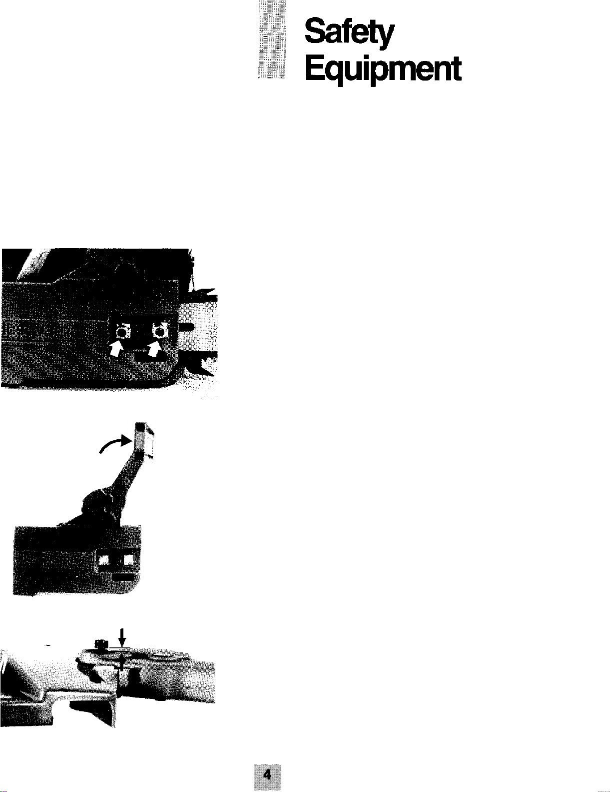
Throttle Trigger Lockout
Disassembly
Press out the pin.
On the 50 and 50 Special models, the throttle lockout
lever has a small tab midway on the left side. Insert a
small screwdriver between the lever and lever opening on
the left side so that the tab will clear the handle then
withdraw the lever out through the top.
www.mymowerparts.com

For Husqvarna Parts Call 606-678-9623 or 606-561-4983
Drive out the pin for the throttle trigger. Raise the throttle
trigger up into the handle and unhook the spring.
Assembly
Insert the spring down through the recess in the handle.
Hook the spring onto throttle trigger.
Align the pin hole in the trigger with the corresponding
hole in the handle and install the pin.
Insert the lockout lever making sure the end of the spring
fits within the lever.
www.mymowerparts.com
For Husqvarna Parts Call 606-678-9623 or 606-561-4983
4
Align the pin holes and drive in the pin. After assembly
check throttle lockout function. It should not be possible
to move the throttle trigger (accelerate the saw) without
first depressing the lockout lever.
NOTE !
On 51 and 55 models, the fast idle system is integrated
into the choke system. When the choke knob is pulled,
the fast idle is engaged for starting purposes. When the
throttle trigger is depressed, the fast idle system
disengages allowing the engine to return to idle when the
trigger is released.
Chain Catcher
Check the chain catcher. If the chain catcher is missing
or damaged, install a new catcher.
www.mymowerparts.com
For Husqvarna Parts Call 606-678-9623 or 606-561-4983
5
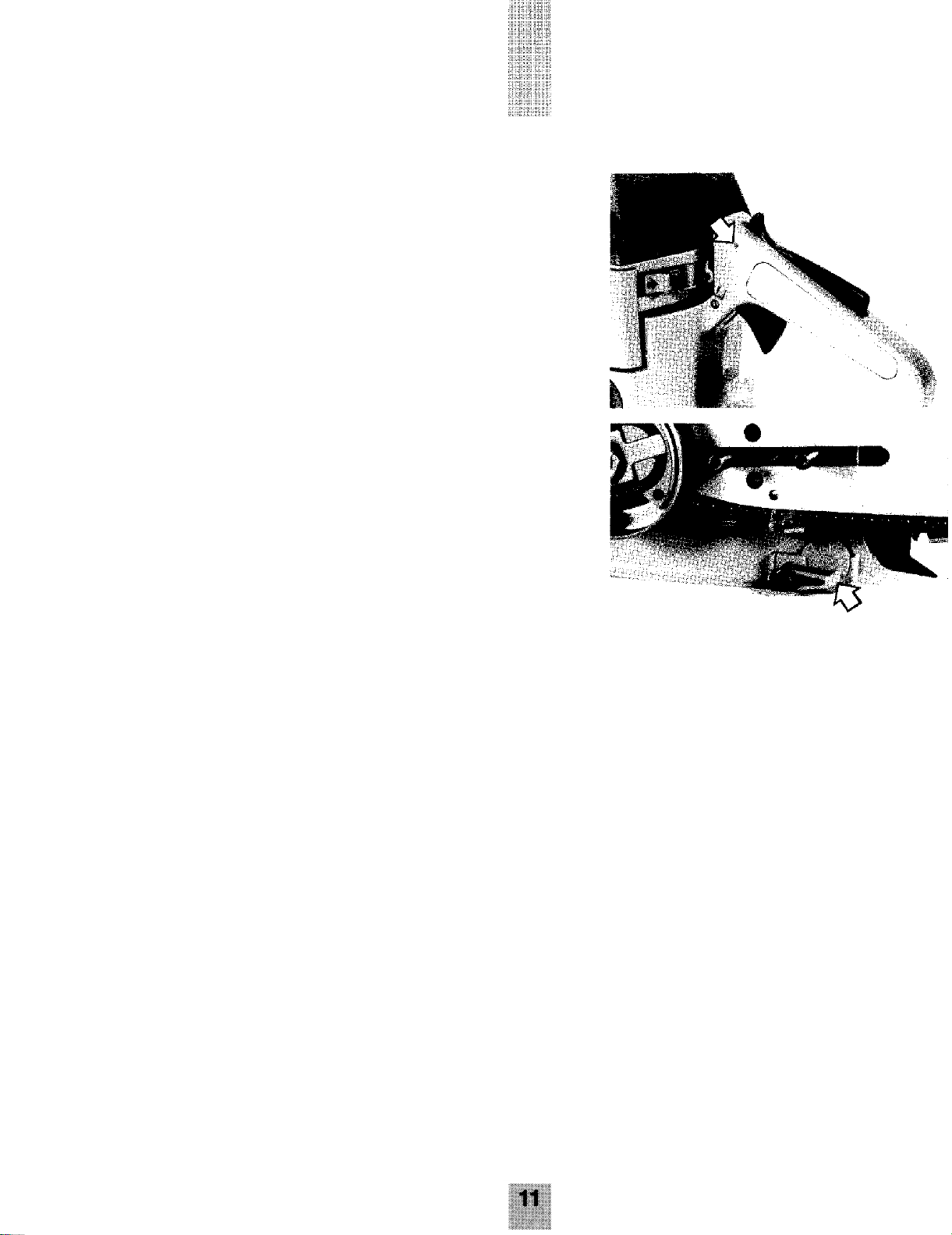
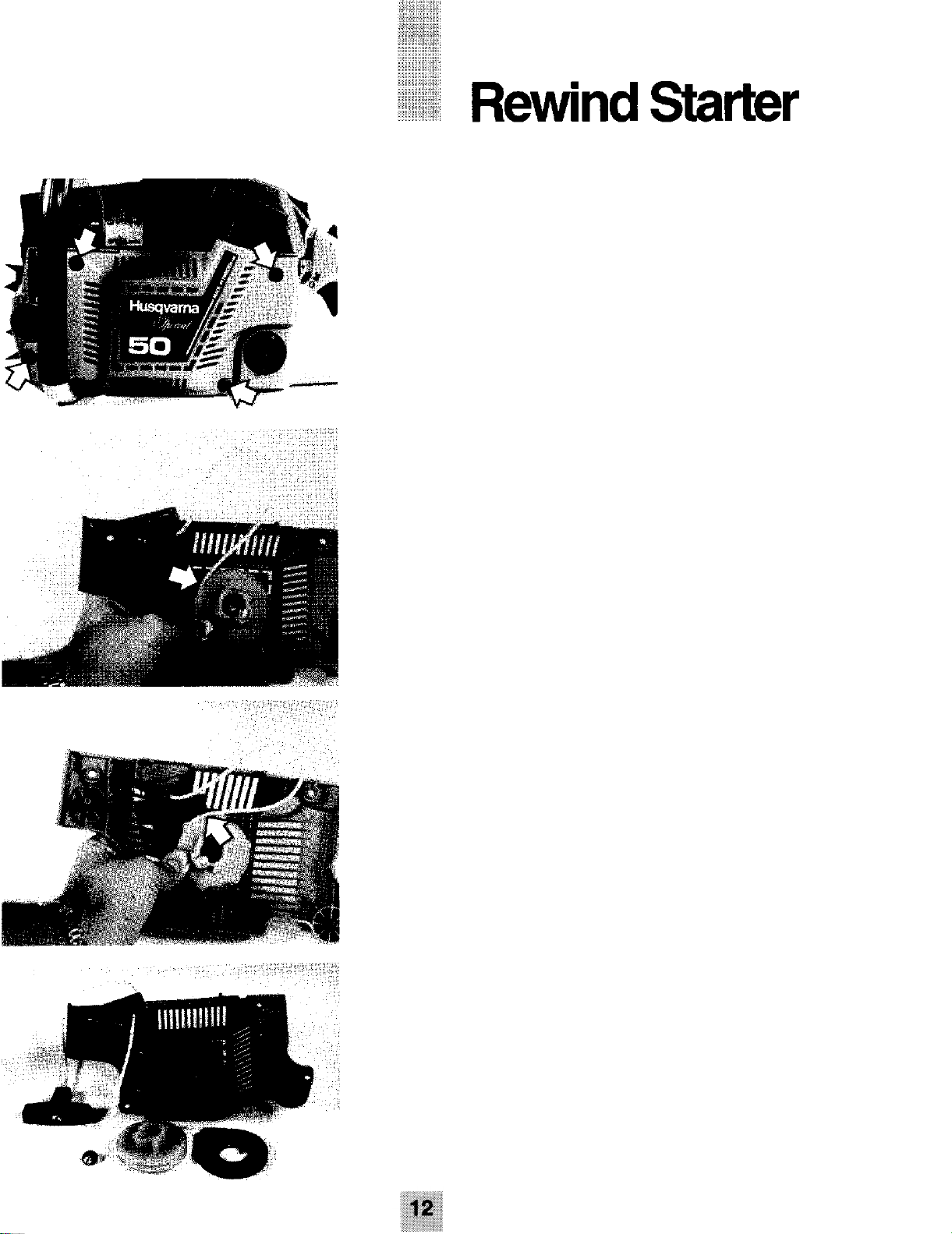
Disassembly
Remove the four starter housing retaining screws and
remove the starter assembly from the crankcase.
If the starter rope is still under tension from the rewind
spring, pull the starter grip out approximately 30 cm (12
inches) and hold starter pulley. Pull a loop of starter rope
up between pulley and housing. On 50 and 50 Special
models, engage rope in pulley notch. On 51 and 55
models, pull rope up between any notched section in
pulley.
Carefully and slowly release the pulley to allow the
rewind spring to unwind. Remove pulley retaining screw
from the starter post and remove the pulley. Carefully
withdraw the recoil spring cassette. Clean all parts
before assembly.
WARNING !
Be very careful when removing and installing the
rewind spring. The rewind
dislodged from the spring cassette causing injuries.
Wear safety goggles for eye protection.
www.mymowerparts.com
spring
can
become

For Husqvarna Parts Call 606-678-9623 or 606-561-4983
5
Assembly
New starter rope length is 88 cm (34.5 inches). Tie a
knot in one end of the rope. Insert the other end through
the rope pulley first, then through the rope eyelet in the
housing and the starter grip.
Tie the rope at the starter grip end with a double loop
knot.
Install the new recoil spring cassette into the housing.
Lubricate the starter post with cold-resistant grease.
Wind 3 turns of the starter cord in a clockwise direction
onto the pulley. Install the rope pulley, washer and
retaining screw.
www.mymowerparts.com

For Husqvarna Parts Call 606-678-9623 or 606-561-4983
Pull the starter cord up into the pulley notch and rotate
the pulley clockwise two turns.
NOTE !
Check that the starter pulley can be turned at least
one half of a turn further when the starter cord is
pulled to the end of rope travel.
To install the starter assembly on crankcase, first pull the
starter grip out approximately 15 cm (6 in.) then position
the housing against the crankcase.
Release the grip so that the pulley engages the starter
pawls on the flywheel. Install and tighten the four starter
retaining screws.
www.mymowerparts.com
For Husqvarna Parts Call 606-678-9623 or 606-561-4983
Ignition
Ignition System
These models are equipped with an electronic ignition
system. One of the characteristics of this system is that
the spark across the spark plug electrode gap has a
higher energy and shorter burning time (arc duration
time). When viewing the spark on a properly functioning
ignition system, the spark will appear to be weaker
compared to breaker point ignition systems due to the
shorter arc duration time.
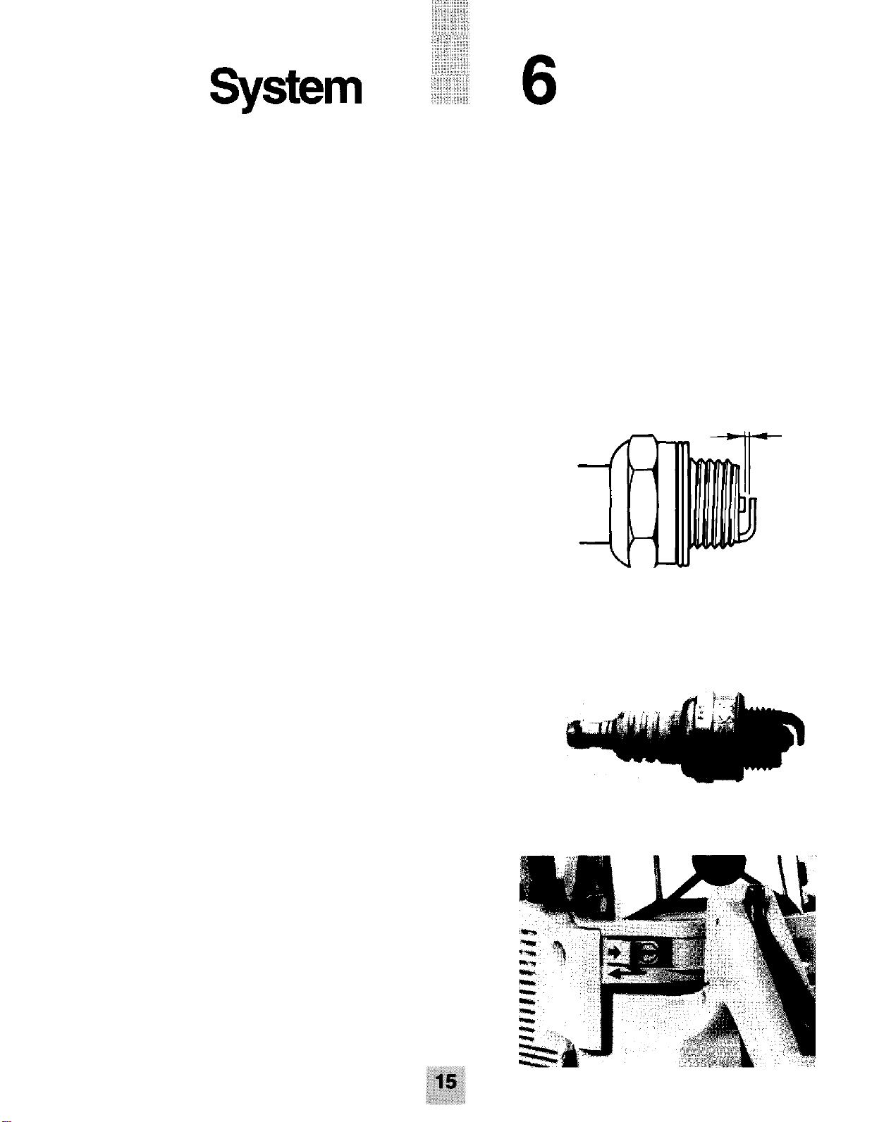
Spark Plug
Champion RCJ7Y and NGK BPMR6A are the only spark
plugs that should be used. The spark plug should be
removed, cleaned and inspected at least once a week.
The spark plug electrode gap should be 0.5 mm
(0.020 in.).
If the electrodes are worn, install a new, properly gapped
spark plug.
Checking for Spark
Remove the spark plug. Move the ignition stop switch to
the “ON” position.
www.mymowerparts.com

For Husqvarna Parts Call 606-678-9623 or 606-561-4983
Attach the high tension lead to the spark plug. Ground
the spark plug against the cylinder. With the-chain saw
secure from movement, pull the starter quickly while
watching for a spark across the spark plug electrode.
If no spark is evident, retest with a new spark plug or test
plug P/N 5027113-01.
If spark is still absent, disconnect the short circuit wire
from the stop switch. Check for spark again as
previously described. If spark occurs, the stop switch is
defective and should be replaced.
If no spark is evident, carefully inspect the full length of
the short circuit wire and the high tension lead to the
spark plug. Ensure that short circuit wire isn’t pinched or
grounded against any metal surface ( i.e., crankcase,
cylinder). Check the high tension lead connector at the
spark plug for a poor connection and the full length of the
lead for breakage or damaged insulation.
www.mymowerparts.com
 Loading...