

Page 1
HP LaserJet P3005 Series printers
Service Manual
Page 2

Copyright information
Safety information
Trademark credits
© 2006 Copyright Hewlett-Packard
Development Company, L.P.
Reproduction, adaptation, or translation
without prior written permission is prohibited,
except as allowed under the copyright laws.
The information contained herein is subject
to change without notice.
The only warranties for HP products and
services are set forth in the express warranty
statements accompanying such products
and services. Nothing herein should be
construed as constituting an additional
warranty. HP shall not be liable for technical
or editorial errors or omissions contained
herein.
Part number: Q7812-90910
Edition 1, 10/2006
WARNING!
Potential Shock Hazard
Always follow basic safety precautions when
using this product to reduce risk of injury from
fire or electric shock.
Read and understand all instructions in the
user guide.
Observe all warnings and instructions
marked on the product.
Use only a grounded electrical outlet when
connecting the product to a power source. If
you do not know whether the outlet is
grounded, check with a qualified electrician.
Do not touch the contacts on the end of any
of the sockets on the product. Replace
damaged cords immediately.
Unplug this product from wall outlets before
cleaning.
Do not install or use this product near water
or when you are wet.
Install the product securely on a stable
surface.
Adobe®, Acrobat®, PostScript®, and the
Acrobat Logo® are trademarks of Adobe
Systems Incorporated.
Java™ is a U.S. trademark of Sun
Microsystems, Inc.
Microsoft®, Windows®, and Windows NT®
are U.S. registered trademarks of Microsoft
Corporation.
UNIX® is a registered trademark of The
Open Group.
ENERGY STAR® and the ENERGY STAR
logo® are U.S. registered marks of the
United States Environmental Protection
Agency.
Install the product in a protected location
where no one can step on or trip over the
power cord and where the power cord will not
be damaged.
If the product does not operate normally, see
the online user guide.
Refer all servicing questions to qualified
personnel.
Information regarding FCC Class B, Parts 15
and 68 requirements can be found in the user
guide.
Page 3

Table of contents
1 Device information
Chapter contents .................................................................................................................................. 1
Device configurations ........................................................................................................................... 2
Features ............................................................................................................................................... 3
Walkaround .......................................................................................................................................... 5
Device parts ......................................................................................................................... 5
Interface ports ...................................................................................................................... 6
Control-panel layout ............................................................................................................. 7
Device software .................................................................................................................................... 9
Minimum system requirements ............................................................................................ 9
Supported operating systems .............................................................................................. 9
Supported printer drivers ................................................................................................... 10
Software for Windows computers ...................................................................................... 10
HP Web Jetadmin ............................................................................................. 10
HP Easy Printer Care software ......................................................................... 10
Supported operating systems ........................................................... 10
Supported browsers ......................................................................... 11
Software for Macintosh computers .................................................................................... 11
Other software ................................................................................................................... 11
Embedded Web server ..................................................................................... 11
Uninstall software .............................................................................................................. 12
Remove software from Windows operating systems ........................................ 12
Remove software from Macintosh operating systems ...................................... 12
Media specifications ........................................................................................................................... 13
Select print media .............................................................................................................. 13
Supported media sizes ...................................................................................... 14
Supported media types ..................................................................................... 15
Paper to avoid .................................................................................................................... 16
2 Installation and configuration
Chapter contents ................................................................................................................................ 17
Site preparation .................................................................................................................................. 18
Location specifications ....................................................................................................... 18
Operating environment ..................................................................................................... 18
Load input trays .................................................................................................................................. 19
Load tray 1 (multipurpose tray) .......................................................................................... 19
Load tray 2 and optional tray 3 ......................................................................................... 21
Install supplies .................................................................................................................................... 23
Supply replacement guidelines .......................................................................................... 23
ENWW iii
Page 4

Install accessories .............................................................................................................................. 26
3 Maintenance
Chapter contents ................................................................................................................................ 33
Manage supplies ................................................................................................................................ 34
Clean the device ................................................................................................................................. 36
Management tools .............................................................................................................................. 38
Change the print cartridge ................................................................................................. 23
Install memory ................................................................................................................... 26
Install device memory ....................................................................................... 26
Check DIMM installation .................................................................................................... 29
Enable memory for Windows ............................................................................................. 30
Use HP Jetdirect print server cards ................................................................................... 30
Install an HP Jetdirect print server card ............................................................ 30
Remove an HP Jetdirect print server card ........................................................ 31
Supplies life ....................................................................................................................... 34
Approximate print-cartridge replacement intervals ............................................................ 34
Manage the print cartridge ................................................................................................. 34
Print-cartridge storage ....................................................................................... 34
Use genuine HP print cartridges ....................................................................... 34
HP policy on non-HP print cartridges ................................................................ 34
Print-cartridge authentication ............................................................................ 35
HP fraud hotline and Web site .......................................................................... 35
Clean the exterior .............................................................................................................. 36
Clean the paper path ......................................................................................................... 36
Clean spilled toner ............................................................................................................. 36
Clean the fuser .................................................................................................................. 36
Use information pages ....................................................................................................... 38
Use the HP Easy Printer Care software ............................................................................ 39
Open the HP Easy Printer Care software ......................................................... 39
HP Easy Printer Care software sections ........................................................... 40
Use the embedded Web server ......................................................................................... 41
Open the embedded Web server by using a network connection ..................... 41
Embedded Web server sections ....................................................................... 41
Use HP Web Jetadmin software ........................................................................................ 43
Use the HP Printer Utility for Macintosh ............................................................................ 43
Open the HP Printer Utility ................................................................................ 44
HP Printer Utility features .................................................................................. 44
4 Theory of operation
Chapter contents ................................................................................................................................ 45
Basic operation ................................................................................................................................... 46
Formatter ........................................................................................................................... 46
Engine control unit (ECU) .................................................................................................. 47
Pickup/feed/delivery system .............................................................................................. 50
Laser/scanner system ........................................................................................................ 51
Image-formation system .................................................................................................... 52
Step 1: Primary charging ................................................................................... 53
Step 2: Laser beam exposure ........................................................................... 53
Step 3: Developing ............................................................................................ 53
iv ENWW
Page 5

Internal components ........................................................................................................................... 56
Timing ................................................................................................................................................. 58
Print cartridge memory system ........................................................................................................... 61
5 Removal and replacement
Chapter contents ................................................................................................................................ 63
Overview ............................................................................................................................................ 65
Removal and replacement strategy .................................................................................. 65
Electrostatic discharge ....................................................................................................... 65
Required tools .................................................................................................................... 65
Types of screws ................................................................................................................. 66
Service approach ............................................................................................................................... 67
Before performing service .................................................................................................. 67
After performing service ..................................................................................................... 68
Covers ................................................................................................................................................ 69
Right-side cover ................................................................................................................. 69
Left-side cover ................................................................................................................... 70
Back cover ......................................................................................................................... 72
I/O cover ............................................................................................................................ 72
Top, right cover .................................................................................................................. 73
Top cover ........................................................................................................................... 74
Front, right cover ................................................................................................................ 75
Control panel ...................................................................................................................................... 78
Formatter ............................................................................................................................................ 80
Fuser .................................................................................................................................................. 83
Laser/scanner ..................................................................................................................................... 86
Engine control unit (ECU) ................................................................................................................... 88
Access plate ....................................................................................................................................... 96
High-voltage power supply ................................................................................................................. 97
Paper feed guide assembly .............................................................................................................. 104
Main motor ....................................................................................................................................... 106
Gear assembly ................................................................................................................................. 108
Reinstallation notes for the gear assembly ...................................................................................... 110
Tray 1 solenoid ................................................................................................................................. 111
Tray 2 solenoid ................................................................................................................................. 112
E-label reader (memory tag) ............................................................................................................ 113
Face-down-roller shaft ...................................................................................................................... 115
Cartridge door .................................................................................................................................. 117
Transfer roller ................................................................................................................................... 120
Registration assembly ...................................................................................................................... 121
Tray 1 pickup roller ........................................................................................................................... 124
Tray 2 pickup roller ........................................................................................................................... 125
Separation pad ................................................................................................................................. 127
Step 4: Transfer ................................................................................................ 54
Step 5: Separation ............................................................................................ 54
Step 6: Fusing ................................................................................................... 54
Step 7: Drum cleaning ....................................................................................... 55
Pre-service procedures ..................................................................................... 67
Parts removal order ........................................................................................... 68
ENWW v
Page 6

6 Troubleshooting
Chapter contents .............................................................................................................................. 129
Troubleshooting process .................................................................................................................. 130
Control-panel messages .................................................................................................................. 131
Clear jams ........................................................................................................................................ 148
Interface troubleshooting ................................................................................................................. 157
Service mode functions .................................................................................................................... 160
Troubleshooting tools ....................................................................................................................... 164
Upgrade the firmware ....................................................................................................................... 168
Troubleshoot general printing problems ........................................................................................... 172
Troubleshoot media handling problems ........................................................................................... 175
Basic troubleshooting ...................................................................................................... 130
Control-panel message types .......................................................................................... 131
Resolve control-panel messages ..................................................................................... 131
Avoid jams ...................................................................................................................... 148
Typical jam locations ....................................................................................................... 149
Jam detection .................................................................................................. 150
Clear jams from the input-tray areas ............................................................... 151
Clear jams from the print-cartridge area ......................................................... 153
Clear jams from the output-bin areas .............................................................. 154
Clear jams from the optional duplexer ............................................................ 155
Communications checks .................................................................................................. 157
Computer direct connect (parallel) test ........................................................... 157
EIO troubleshooting ......................................................................................................... 157
Jetdirect page .................................................................................................. 158
Network printing problems ............................................................................................... 158
Cold reset ........................................................................................................................ 160
NVRAM initialization ........................................................................................................ 160
Hard-disk initialization ...................................................................................................... 161
Skip disk-load .................................................................................................................. 161
Self test ............................................................................................................................ 161
Service menu (service PIN codes) .................................................................................. 161
Service ID ........................................................................................................................ 162
Restoring the service ID .................................................................................. 162
Convert the service ID to an actual date ......................................................... 163
Control-panel menus ....................................................................................................... 164
Diagnostics menu ............................................................................................ 164
Test pages ...................................................................................................................... 165
Engine-test page ............................................................................................. 165
Formatter test page ......................................................................................... 166
Image defect ruler ............................................................................................................ 167
Determine the current firmware version ........................................................................... 168
Download the new firmware from the HP Web site ......................................................... 168
Transfer the new firmware to the device .......................................................................... 168
Use FTP to upgrade the firmware on a network connection ........................... 168
Use HP Web Jetadmin to upgrade the firmware ............................................. 169
Use MS-DOS commands to upgrade the firmware ......................................... 170
Upgrade the HP Jetdirect firmware .................................................................................. 171
Multiple pages feed .......................................................................................................... 175
Pages are wrinkled or folded ........................................................................................... 175
vi ENWW
Page 7

Pages are skewed ........................................................................................................... 175
Troubleshoot print-quality problems ................................................................................................ 177
Print-quality checklist ....................................................................................................... 177
Image-defect examples ................................................................................................... 178
Light print (partial page) .................................................................................................. 179
Light print (entire page) ................................................................................................... 180
Specks ............................................................................................................................. 180
Dropouts .......................................................................................................................... 181
Lines ................................................................................................................................ 181
Gray background ............................................................................................................ 182
Toner smear ................................................................................................................... 182
Loose toner ..................................................................................................................... 183
Repeating defects ........................................................................................................... 183
Repeating image ............................................................................................................. 184
Misformed characters ...................................................................................................... 184
Page skew ....................................................................................................................... 185
Curl or wave .................................................................................................................... 185
Wrinkles or creases ......................................................................................................... 186
Vertical white lines ........................................................................................................... 186
Tire tracks ....................................................................................................................... 187
White spots on black ....................................................................................................... 187
Scattered lines ................................................................................................................ 188
Blurred print .................................................................................................................... 188
Random image repetition ................................................................................................. 189
Diagrams .......................................................................................................................................... 190
Device component locations ............................................................................................ 190
Main assemblies ............................................................................................. 190
Main parts ....................................................................................................... 191
Sensors and switches ..................................................................................... 192
Motors, fans, and solenoids ............................................................................ 193
PCAs ............................................................................................................... 194
Wiring diagrams ............................................................................................................... 194
7 Parts and diagrams
Chapter contents .............................................................................................................................. 199
Order parts, accessories, and supplies ............................................................................................ 200
Order directly from HP ..................................................................................................... 200
Order through service or support providers ..................................................................... 200
Order directly through the embedded Web server (for printers that are connected to a
network) ........................................................................................................................... 200
Order directly through the HP Easy Printer Care software .............................................. 200
Part numbers .................................................................................................................................... 201
Paper-handling accessories ............................................................................................ 201
Print cartridge .................................................................................................................. 201
Memory ............................................................................................................................ 201
Cables and interfaces ...................................................................................................... 202
Covers .............................................................................................................................................. 204
Internal components ......................................................................................................................... 206
Tray 2 pickup assembly .................................................................................................................... 222
Alphabetical parts list ....................................................................................................................... 224
ENWW vii
Page 8

Numerical parts list ........................................................................................................................... 233
Appendix A Specifications
Physical specifications ..................................................................................................................... 244
Electrical specifications .................................................................................................................... 245
Acoustic specifications ..................................................................................................................... 246
Operating environment ..................................................................................................................... 246
Appendix B Service and support
Hewlett-Packard limited warranty statement .................................................................................... 247
Customer self repair warranty service .............................................................................................. 248
Print cartridge limited warranty statement ........................................................................................ 249
HP Customer Care ........................................................................................................................... 250
Online Services ................................................................................................................ 250
Telephone support ........................................................................................................... 250
Software utilities, drivers, and electronic information ....................................................... 250
HP direct ordering for accessories or supplies ................................................................ 250
HP service information ..................................................................................................... 250
HP service agreements ................................................................................................... 250
HP Easy Printer Care software ........................................................................................ 251
HP support and information for Macintosh computers ..................................................... 251
HP maintenance agreements ........................................................................................................... 252
On-site service agreements ............................................................................................. 252
Next-day on-site service .................................................................................. 252
Weekly (volume) on-site service ..................................................................... 252
Repacking the device ...................................................................................................... 252
Extended warranty ........................................................................................................... 253
Appendix C Regulatory information
FCC regulations ............................................................................................................................... 256
Environmental product stewardship program ................................................................................... 257
Protecting the environment .............................................................................................. 257
Ozone production ............................................................................................................ 257
Power consumption ......................................................................................................... 257
Toner consumption .......................................................................................................... 257
Paper use ........................................................................................................................ 257
Plastics ............................................................................................................................ 257
HP LaserJet print supplies ............................................................................................... 257
HP print supplies returns and recycling program information .......................................... 258
Paper ............................................................................................................................... 258
Material restrictions .......................................................................................................... 258
Disposal of waste equipment by users in private households in the European
Union ............................................................................................................................... 259
Material Safety Data Sheet (MSDS) ................................................................................ 259
For more information ....................................................................................................... 259
Declaration of conformity .................................................................................................................. 261
Safety statements ............................................................................................................................. 262
Laser safety ..................................................................................................................... 262
Canadian DOC regulations .............................................................................................. 262
viii ENWW
Page 9

VCCI statement (Japan) .................................................................................................. 262
Power cord statement (Japan) ......................................................................................... 262
EMI statement (Korea) ..................................................................................................... 262
Laser statement for Finland ............................................................................................. 263
Index ................................................................................................................................................................. 265
ENWW ix
Page 10

List of tables
Table 1-1 Supported media sizes ..................................................................................................................... 14
Table 1-2 Automatic 2-sided printing ............................................................................................................... 14
Table 1-3 Tray 1 media types ........................................................................................................................... 15
Table 1-4 Tray 2 and tray 3 media types .......................................................................................................... 15
Table 4-1 Operation sequences ....................................................................................................................... 58
Table 4-2 Power-on sequence ......................................................................................................................... 58
Table 6-1 Common causes of jams ................................................................................................................ 148
Table 6-2 Diagnostics menu ........................................................................................................................... 164
Table 6-3 Causes for multiple pages feeding ................................................................................................. 175
Table 6-4 Causes for wrinkled or folded paper at the paper-path entrance ................................................... 175
Table 6-5 Causes for wrinkled or folded paper at the paper-path exit ........................................................... 175
Table 6-6 Causes for skewed pages .............................................................................................................. 175
Table 7-1 Covers ............................................................................................................................................ 205
Table 7-2 Internal components (1 of 6) .......................................................................................................... 207
Table 7-3 Internal components (2 of 6) .......................................................................................................... 211
Table 7-4 Internal components (3 of 6) .......................................................................................................... 215
Table 7-5 Internal components (4 of 6) .......................................................................................................... 217
Table 7-6 Internal components (5 of 6) .......................................................................................................... 219
Table 7-7 Internal components (6 of 6) .......................................................................................................... 221
Table 7-8 Tray 2 pickup assembly ................................................................................................................. 223
Table 7-9 Alphabetical parts list ..................................................................................................................... 224
Table 7-10 Numerical parts list ....................................................................................................................... 233
Table A-1 Device dimensions ......................................................................................................................... 244
Table A-2 Device dimensions with all doors and trays fully opened .............................................................. 244
Table A-3 Power requirements ....................................................................................................................... 245
Table A-4 Power consumption (average, in watts) ........................................................................................ 245
Table A-5 Sound power and pressure level ................................................................................................... 246
Table A-6 Necessary conditions ..................................................................................................................... 246
ENWW xi
Page 11

List of figures
Figure 1-1 Model and serial numbers ................................................................................................................. 6
Figure 4-1 Systems overview ........................................................................................................................... 46
Figure 4-2 Print engine general structure ......................................................................................................... 47
Figure 4-3 Engine control system circuit diagram ............................................................................................ 48
Figure 4-4 Low-voltage power supply circuit diagram ...................................................................................... 49
Figure 4-5 Pickup/feed/delivery system ........................................................................................................... 50
Figure 4-6 Laser/scanner system ..................................................................................................................... 51
Figure 4-7 Print cartridge diagram .................................................................................................................... 52
Figure 4-8 Image-formation system ................................................................................................................. 52
Figure 4-9 Primary charging ............................................................................................................................. 53
Figure 4-10 Developing .................................................................................................................................... 53
Figure 4-11 Transfer ......................................................................................................................................... 54
Figure 4-12 Separation ..................................................................................................................................... 54
Figure 4-13 Fusing ........................................................................................................................................... 55
Figure 4-14 Drum cleaning ............................................................................................................................... 55
Figure 4-15 Cross-section of device ................................................................................................................. 56
Figure 4-16 Operational sequences ................................................................................................................. 59
Figure 4-17 Timing diagram ............................................................................................................................. 60
Figure 4-18 Print cartridge memory tag ............................................................................................................ 61
Figure 5-1 Parts removal diagram .................................................................................................................... 68
Figure 5-2 Removing the right-side cover ........................................................................................................ 69
Figure 5-3 Removing the left-side cover (1 of 2) .............................................................................................. 70
Figure 5-4 Removing the left-side cover (2 of 2) .............................................................................................. 71
Figure 5-5 Removing the back cover ............................................................................................................... 72
Figure 5-6 Removing the I/O cover .................................................................................................................. 73
Figure 5-7 Removing the top, right cover ......................................................................................................... 74
Figure 5-8 Removing the top cover .................................................................................................................. 75
Figure 5-9 Removing the front, right cover (1 of 2) .......................................................................................... 76
Figure 5-10 Removing the front, right cover (2 of 2) ........................................................................................ 77
Figure 5-11 Removing the control panel .......................................................................................................... 78
Figure 5-12 Reinstalling the control panel ........................................................................................................ 79
Figure 5-13 Removing the formatter (1 of 3) .................................................................................................... 80
Figure 5-14 Removing the formatter (2 of 3) .................................................................................................... 81
Figure 5-15 Removing the formatter (3 of 3) .................................................................................................... 82
Figure 5-16 Removing the fuser (1 of 3) .......................................................................................................... 83
Figure 5-17 Removing the fuser (2 of 3) .......................................................................................................... 84
Figure 5-18 Removing the fuser (3 of 3) .......................................................................................................... 85
Figure 5-19 Removing the laser/scanner (1 of 2) ............................................................................................. 86
Figure 5-20 Removing the laser/scanner (2 of 2) ............................................................................................. 87
ENWW
xiii
Page 12

Figure 5-21 Removing the ECU (1 of 8) ........................................................................................................... 88
Figure 5-22 Removing the ECU (2 of 8) ........................................................................................................... 89
Figure 5-23 Removing the ECU (3 of 8) ........................................................................................................... 90
Figure 5-24 Removing the ECU (4 of 8) ........................................................................................................... 91
Figure 5-25 Removing the ECU (5 of 8) ........................................................................................................... 92
Figure 5-26 Removing the ECU (6 of 8) ........................................................................................................... 93
Figure 5-27 Removing the ECU (7 of 8) ........................................................................................................... 94
Figure 5-28 Removing the ECU (8 of 8) ........................................................................................................... 95
Figure 5-29 Removing the access plate (1 of 2) .............................................................................................. 96
Figure 5-30 Removing the access plate (2 of 2) .............................................................................................. 96
Figure 5-31 Removing the power supply (1 of 5) ............................................................................................. 97
Figure 5-32 Removing the power supply (2 of 5) ............................................................................................. 98
Figure 5-33 Removing the power supply (3 of 5) ............................................................................................. 99
Figure 5-34 Removing the power supply (4 of 5) ........................................................................................... 100
Figure 5-35 Removing the power supply (5 of 5) ........................................................................................... 101
Figure 5-36 Grounding-spring locations ......................................................................................................... 102
Figure 5-37 Reinstalling the oblique-roller assembly .................................................................................... 103
Figure 5-38 Removing the paper feed guide assembly ................................................................................. 104
Figure 5-39 Removing the main motor (1 of 2) .............................................................................................. 106
Figure 5-40 Removing the main motor (2 of 2) .............................................................................................. 107
Figure 5-41 Removing the gear assembly (1 of 3) ......................................................................................... 108
Figure 5-42 Removing the gear assembly (3 of 3) ......................................................................................... 109
Figure 5-43 Reinstalling the gear assembly ................................................................................................... 110
Figure 5-44 Removing the tray 1 solenoid ..................................................................................................... 111
Figure 5-45 Removing the tray 2 solenoid ..................................................................................................... 112
Figure 5-46 Removing the e-label reader (1 of 2) .......................................................................................... 113
Figure 5-47 Removing the e-label reader (2 of 2) .......................................................................................... 114
Figure 5-48 Removing the face-down-roller shaft (1 of 2) .............................................................................. 115
Figure 5-49 Removing the face-down-roller shaft (2 of 2) .............................................................................. 116
Figure 5-50 Removing the cartridge door (1 of 3) .......................................................................................... 117
Figure 5-51 Removing the cartridge door (2 of 3) .......................................................................................... 118
Figure 5-52 Removing the cartridge door (3 of 3) .......................................................................................... 119
Figure 5-53 Removing the transfer roller ........................................................................................................ 120
Figure 5-54 Removing the registration assembly (1 of 3) .............................................................................. 121
Figure 5-55 Removing the registration assembly (2 of 3) .............................................................................. 122
Figure 5-56 Removing the registration assembly (3 of 3) .............................................................................. 123
Figure 5-57 Removing the tray 1 pickup roller ............................................................................................... 124
Figure 5-58 Removing the tray 2 pickup roller (1 of 2) ................................................................................... 125
Figure 5-59 Removing the tray 2 pickup roller (2 of 2) ................................................................................... 126
Figure 5-60 Removing the separation pad ..................................................................................................... 127
Figure 6-1 Jam-detection sensors .................................................................................................................. 150
Figure 6-2 Jetdirect page ............................................................................................................................... 158
Figure 6-3 Locating the engine-test-page switch ........................................................................................... 166
Figure 6-4 Main assemblies ....................................................................................................
Figure 6-5 Main parts ..................................................................................................................................... 191
Figure 6-6 Sensors and switches ................................................................................................................... 192
Figure 6-7 Motors, fans, and solenoids .......................................................................................................... 193
Figure 6-8 PCAs ............................................................................................................................................. 194
Figure 6-9 ECU wiring .................................................................................................................................... 195
Figure 6-10 Circuit diagram (1 of 2) ............................................................................................................... 196
....................... 190
xiv ENWW
Page 13

Figure 6-11 Circuit diagram (2 of 2) ............................................................................................................... 197
Figure 7-1 Covers ........................................................................................................................................... 204
Figure 7-2 Internal components (1 of 6) ......................................................................................................... 206
Figure 7-3 Internal components (2 of 6) ......................................................................................................... 210
Figure 7-4 Internal components (3 of 6) ......................................................................................................... 214
Figure 7-5 Internal components (4 of 6) ......................................................................................................... 216
Figure 7-6 Internal components (5 of 6) ......................................................................................................... 218
Figure 7-7 Internal components (6 of 6) ......................................................................................................... 220
Figure 7-8 Tray 2 pickup assembly ................................................................................................................ 222
ENWW xv
Page 14

1 Device information
Chapter contents
Device configurations
●
Features
●
Walkaround
●
Device software
●
Media specifications
●
ENWW Chapter contents 1
Page 15

Device configurations
HP LaserJet P3005 HP LaserJet P3005d HP LaserJet P3005n HP LaserJet
P3005dn
Prints up to
●
35 pages-perminute (ppm) on
letter-sized media,
and up to 33 ppm on
A4-sized media
48 megabytes (MB)
●
total of random
access memory
(RAM)
100-sheet
●
multipurpose tray
(tray 1), 500-sheet
input tray (tray 2),
and 250-sheet
output bin
Hi-Speed universal
●
serial bus (USB) 2.0
port
HP LaserJet P3005,
plus:
Automatic two-
●
sided printing
accessory
64 MB total RAM
●
IEEE 1284B-
●
compliant parallel
connection port
Prints up to
●
35 pages-perminute (ppm) on
letter-sized
media, and up to
33 ppm on A4sized media
80 MB total
●
RAM
100-sheet
●
multipurpose
tray (tray 1), 500sheet input tray
(tray 2), and 250sheet output bin
Hi-Speed
●
universal serial
bus (USB) 2.0
port
HP LaserJet P3005n,
plus:
Automatic two-
●
sided printing
accessory
HP LaserJet P3005x
HP LaserJet P3005n,
plus:
Automatic two-
●
sided printing
accessory
500-sheet input
●
tray (tray 3)
One open dual inline
●
memory module
(DIMM) slot
Enhanced input/
●
output (EIO) slot
IEEE 1284B-
●
compliant parallel
connection port (not
available on
network-connected
models)
One open dual
●
inline memory
module (DIMM)
slot
Enhanced input/
●
output (EIO) slot
HP Jetdirect full-
●
featured
embedded print
server to connect
to 10Base-T/
100Base-TX
networks
2 Chapter 1 Device information ENWW
Page 16

Features
Feature Description
Performance
User interface
Printer drivers
Resolution
Storage features
Fonts
400 MHz processor
●
Control-panel help
●
HP Easy Printer Care software (a Web-based status and problem-solving tool)
●
Windows® and Macintosh printer drivers
●
Embedded Web server to access support and order supplies (for network-connected models
●
only)
HP PCL 5
●
HP PCL 6
●
HP postscript level 3 emulation
●
FastRes 1200—produces 1200-dots-per-inch (dpi) print quality for fast, high-quality printing of
●
business text and graphics
ProRes 1200—produces 1200-dpi printing for the best quality in line art and graphic images
●
Fonts, forms, and other macros
●
Job retention
●
93 internal scalable fonts available for PCL and HP postscript 3 emulation
●
80 device-matching screen fonts in TrueType format available with the software solution
●
Additional fonts can be added through the host USB ports
●
Accessories
Connectivity
Environmental features
Optional 500-sheet input tray (tray 3) (available for all models except HP LaserJet P3005x)
●
Automatic duplexer (available only on models HP LaserJet P3005d, HP LaserJet P3005dn,
●
and HP LaserJet P3005x)
144-pin dual inline memory module (DIMM)
●
Hi-Speed USB 2.0 connection
●
HP Jetdirect full-featured embedded print server (available only on models HP LaserJet
●
P3005n, HP LaserJet P3005dn, and HP LaserJet P3005x)
IEEE-1284 compliant parallel port (available only on models HP LaserJet P3005 and
●
HP LaserJet P3005d)
HP Web Jetadmin software
●
Enhanced input/output (EIO) slot
●
Sleep mode
●
ENERGY STAR® qualified
●
ENWW Features 3
Page 17

Feature Description
Supplies
Accessibility
The supplies status page contains information about toner level, page count, and estimated
●
pages remaining.
The device checks for an authentic HP print cartridge at installation.
●
Internet-enabled supply-ordering capabilities (using HP Easy Printer Care software)
●
The online user guide is compatible with text screen-readers.
●
The print cartridge can be installed and removed by using one hand.
●
All doors and covers can be opened by using one hand.
●
Media can be loaded in tray 1 by using one hand.
●
4 Chapter 1 Device information ENWW
Page 18
Walkaround
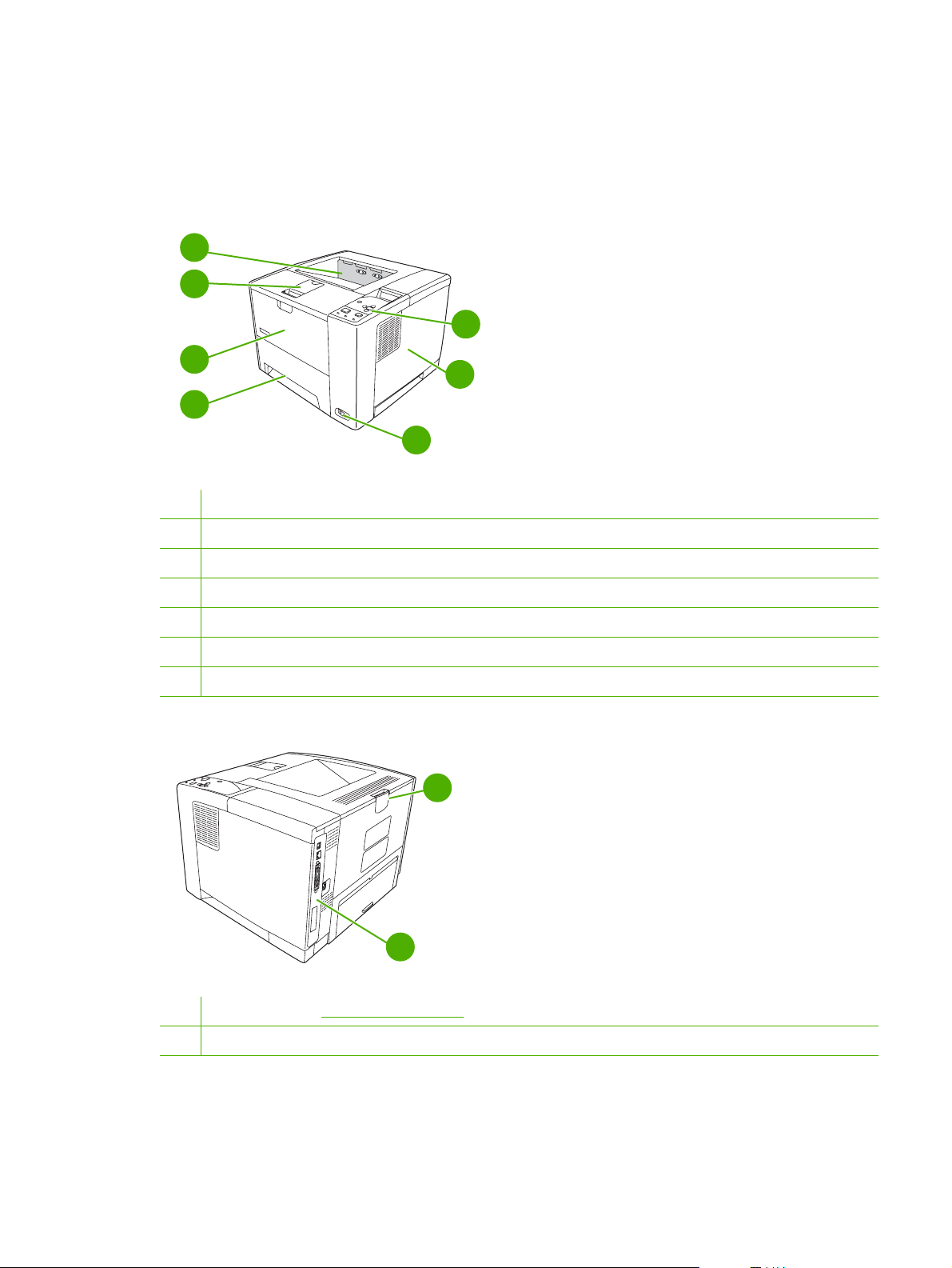
Device parts
Before using the device, familiarize yourself with the parts of the device.
1
2
5
3
6
4
7
1 Top output bin
2 Latch to open the cartridge door (provides access to the print cartridge)
3 Tray 1 (pull to open)
4 Tray 2
5 Control panel
6 Right-side cover (provides access to DIMMs)
7 On/off switch
2
1
1 Interface ports (see Interface ports on page 6)
2 Rear output bin (pull to open)
The model number and serial numbers are listed on the identification labels located on the back of the
device. The model number is alphanumeric, such as Q7812A for an HP LaserJet P3005 printer. The
ENWW Walkaround 5
Page 19
serial number contains information about the country/region of origin, the device version, production
code, and the production number of the device. The following is a sample identification label.
country/region of origin printer version production number
model number production code
HEWLETT-PACKARD
11311 CHINDEN BLVD.
BOISE, IDAHO 83714
USA
Assembled in U.S.A. printer engine made in Japan
50/60 Hz. 115V
Model No.: Q3668
CNBR212347
CNBR212347
Serial No.: JPBB605112
CNBR212347
CNBR212347
Figure 1-1 Model and serial numbers
Model name Model number
HP LaserJet P3005 Q7812A
HP LaserJet P3005d Q7813A
HP LaserJet P3005n Q7814A
HP LaserJet P3005dn Q7815A
HP LaserJet P3005x Q7816A
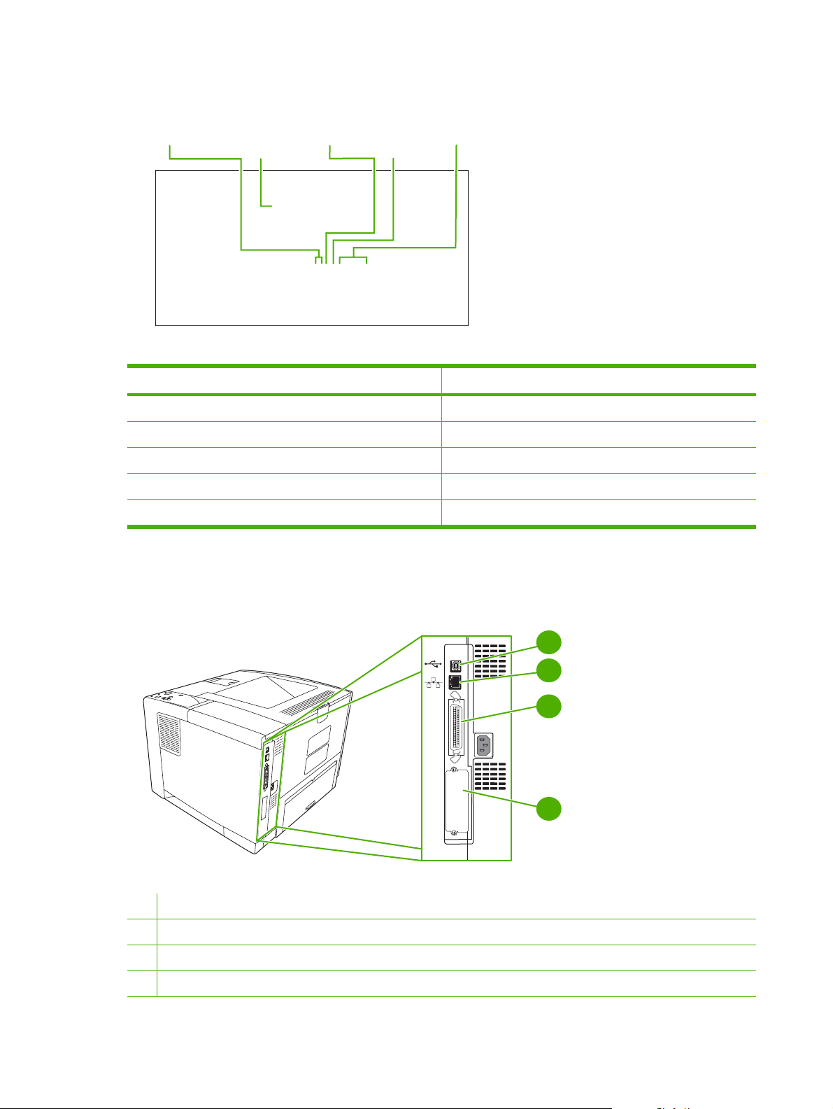
Interface ports
The device has one EIO slot and three ports for connecting to a computer or a network.
1 Type B Hi-Speed USB 2.0 connection
EIO
1
2
3
4
2 RJ-45 network connection (available only on models P3005n, P3005dn, and P3005x)
3 IEEE 1284B-compliant parallel connection (available only on models P3005 and P3005d)
4 EIO slot
6 Chapter 1 Device information ENWW
Page 20
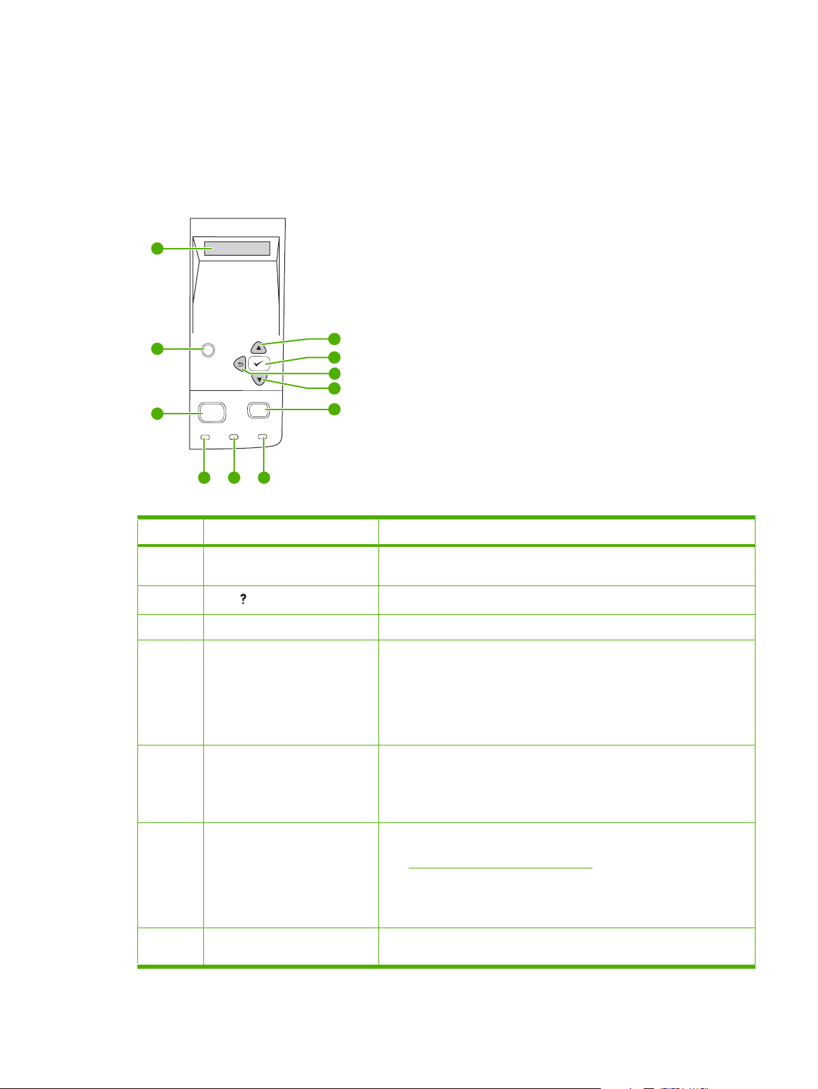
Control-panel layout
The control-panel display gives you complete, timely information about the device and print jobs. Menus
provide access to device functions and detailed information.
The message and prompt areas of the display alert you to the state of the device and tell you how to
respond.
1
2
3
Number Button or light Function
1 Control-panel display
2
3 Menu button
4 Ready light
?
Menu Stop
Ready Data Attention
4 5 6
Help ( ) button
11
10
9
8
7
Shows status information, menus, help information, and error
●
messages.
Provides information about the message on the control-panel display.
●
Opens and closes the menus.
●
On: The device is online and ready to accept data to print.
●
Off: The device cannot accept data because it is offline (paused) or has
●
experienced an error.
Blinking: The device is going offline. The device stops processing the
●
current print job and expels all of the active pages from the paper path.
5 Data light
6 Attention light
7 Stop button
On: The device has data to print, but is waiting to receive all of the data.
●
Off: The device has no data to print.
●
Blinking: The device is processing or printing the data.
●
On: The device has experienced a problem. Make note of the message
●
on the control-panel display, and then turn the device off and on. See
Control-panel messages on page 131 for help in resolving problems.
Off: The device is functioning without error.
●
Blinking: Action is required. See the control-panel display.
●
Cancels the current print job and clears the pages from the device. The
●
time this takes depends on the size of the print job. (Press the button
ENWW Walkaround 7
Page 21

Number Button or light Function
only once.) Also clears continuable errors that are associated with the
canceled job.
NOTE The control-panel lights cycle while the print job is cleared
from both the device and the computer, and then the device returns
to the Ready state.
8
9
10
11
Down ( ) button
Back ( ) button
Select ( ) button
Up ( ) button
Navigates to the next item in the list, or decreases the value of numeric
●
items
Backs up one level in the menu tree or backs up one numeric entry
●
Closes menus if held down for more than 1 second
●
Clears an error condition when the condition is clearable
●
Saves the selected value for an item
●
Performs the action that is associated with the item that is highlighted
●
on the control-panel display
Navigates to the previous item in the list, or increases the value of
●
numeric items
8 Chapter 1 Device information ENWW
Page 22

Device software
The printing-system software is included with the device. See the getting started guide for installation
instructions.
The printing system includes software for end users and network administrators, and printer drivers for
access to the device features and communication with the computer.
NOTE For a list of printer drivers and updated HP device software, go to www.hp.com/go/
LJP3005_software.
Minimum system requirements
In order to install and use the device software, your computer must meet the following minimum
requirements:
Windows requirements
Pentium II (233 MHz) processor
●
64 MB of RAM
●
35 MB of disk space
●
SVGA 800x600 16-bit color monitor
●
Macintosh requirements
G3, G4, or G5 PowerPC processor
●
128 MB of RAM
●
30 to 50 MB of disk space
●
Supported operating systems
The device supports the following operating systems:
Full software installation
Windows XP (32-bit)
●
Windows 2000
●
Mac OS X V10.2 and later
●
Printer driver only
Windows 98 SE
●
Windows Millennium Edition (Me)
●
Windows Server 2003
●
Windows XP (64-bit)
●
Linux
●
ENWW Device software 9
Page 23

Supported printer drivers
Operating system
Windows
Mac OS X V10.2 and later
Linux
1
2
2,3
4
Not all device features are available from all drivers or operating systems.
For Windows 2000 and Windows XP (32-bit and 64-bit), download the PCL 5 driver from
1
www.hp.com/go/LJP3005_software.
3
For Windows XP (64-bit), download the PCL 6 driver from www.hp.com/go/LJP3005_software.
4
For Linux, download the postscript level 3 emulation driver from www.hp.com/go/linuxprinting.
The printer drivers include online Help that has instructions for common printing tasks and also describes
the buttons, checkboxes, and drop-down lists that are in the printer driver.
Software for Windows computers
HP Web Jetadmin
HP Web Jetadmin is a browser-based management tool for HP Jetdirect-connected printers within your
intranet, and it should be be installed only on the network administrator’s computer.
PCL 5 PCL 6 PS level 3 emulation
To download a current version of HP Web Jetadmin and for the latest list of supported host systems,
www.hp.com/go/webjetadmin.
visit
When installed on a host server, any client can gain access to HP Web Jetadmin by using a supported
Web browser (such as Microsoft® Internet Explorer 4.x or Netscape Navigator 4.x or later) by navigating
to the HP Web Jetadmin host.
HP Easy Printer Care software
The HP Easy Printer Care software is a program that you can use for the following tasks:
Checking the device status
●
Checking the supplies status
●
Setting up alerts
●
Viewing device documentation
●
Gaining access to troubleshooting and maintenance tools
●
You can view the HP Easy Printer Care software when the device is directly connected to your computer
or when it is connected to a network. To download the HP Easy Printer Care software, go to
www.hp.com/go/easyprintercare.
Supported operating systems
For information about supported operating systems, go to
www.hp.com/go/easyprintercare.
10 Chapter 1 Device information ENWW
Page 24

Supported browsers
To use the HP Easy Printer Care software, you must have one of the following browsers:
Microsoft Internet Explorer 5.5 or later
●
Netscape Navigator 7.0 or later
●
Opera Software ASA Opera 6.05 or later
●
All pages can be printed from the browser.
Software for Macintosh computers
The HP installer provides PostScript® Printer Description (PPD) files, Printer Dialog Extensions (PDEs),
and the HP Printer Utility for use with Macintosh computers.
For network connections, use the embedded Web server (EWS) to configure the device. See
Web server on page 11.
The printing system software includes the following components:
PostScript Printer Description (PPD) files
●
The PPDs, in combination with the Apple PostScript printer drivers, provide access to device
features and allows the computer to communicate with the device.
An installation program for the PPDs, PDEs, and other software is provided on the CD-ROM. Use
the appropriate PS driver that comes with the operating system.
HP Printer Utility
●
Use the HP Printer Utility to set up device features that are not available in the printer driver:
Name the device.
●
Assign the device to a zone on the network.
●
Assign an internet protocol (IP) address to the device.
●
Download files and fonts.
●
Configure the device for IP or AppleTalk printing.
●
You can use the HP Printer Utility when your device uses a universal serial bus (USB) cable or is
connected to a TCP/IP-based network. For more information, see
Macintosh on page 43.
Use the HP Printer Utility for
Embedded
NOTE The HP Printer Utility is supported for Mac OS X V10.2 or later.
Other software
Embedded Web server
The device is equipped with an embedded Web server, which provides access to information about
device and network activities. This information appears in a Web browser, such as Microsoft Internet
Explorer or Netscape Navigator.
ENWW Device software 11
Page 25

The embedded Web server resides on the device. It is not loaded on a network server.
The embedded Web server provides an interface to the device that anyone who has a networkconnected computer and a standard Web browser can use. No special software is installed or
configured, but you must have a supported Web browser on your computer. To gain access to the
embedded Web server, type the IP address for the device in the address line of the browser. (To find
the IP address, print a configuration page. For more information about printing a configuration page,
Use information pages on page 38.)
see
For a complete explanation of the features and functionality of the embedded Web server, see
embedded Web server on page 41.
Uninstall software
Remove software from Windows operating systems
1. Click Start, and then click All Programs.
2. Click HP, and then click HP LaserJet P3005.
3. Click Uninstall HP LaserJet P3005, and then follow the onscreen instructions to remove the
software.
Remove software from Macintosh operating systems
To remove the software from a Macintosh computer, drag the PPD files to the trash can.
Use the
12 Chapter 1 Device information ENWW
Page 26

Media specifications
The device accepts a variety of media, such as cut-sheet paper, including up to 100% recycled fiber
content paper; envelopes; labels; transparencies; and custom-size paper. Properties such as weight,
composition, grain, and moisture content are important factors that affect device performance and output
quality. Media that does not meet the guidelines that are outlined in this manual can cause the following
problems:
Poor print quality
●
Increased jams
●
Premature wear on the device, requiring repair
●
NOTE Some media might meet all of media specifications and still not produce satisfactory
results. Improper handling, unacceptable temperature and humidity levels, and other variables
over which Hewlett-Packard has no control can affect print quality. Before purchasing large
quantities of media, make sure that it meets the requirements that are specified in the user guide
and in theHP LaserJet Printer Family Print Media Guide, which is available for download at
www.hp.com/support/ljpaperguide. Always test paper before buying large quantities.
CAUTION Using media that does not meet HP specifications can cause problems for the
device, requiring repair. This repair is not covered by the HP warranty or service agreements.
Select print media
This device accepts a variety of media, such as cut-sheet paper, including up to 100% recycled fiber
content paper; envelopes; labels; transparencies; and custom-size paper. Properties such as weight,
composition, grain, and moisture content are important factors that affect device performance and output
quality. Paper that does not meet the guidelines that are outlined in this manual can cause the following
problems:
Poor print quality
●
Increased jams
●
Premature wear on the device, requiring repair
●
NOTE Some paper might meet all of the guidelines in this manual and still not produce
satisfactory results. This might be the result of improper handling, unacceptable temperature and
humidity levels, or other variables over which Hewlett-Packard has no control. Before purchasing
large quantities of media, make sure that it meets the requirements that are specified in this user
guide and in the HP LaserJet Printer Family Print Media Guide, which is available for download
www.hp.com/support/ljpaperguide. Always test paper before buying large quantities.
at
CAUTION Using media that does not meet HP specifications can cause problems for the
device, requiring repair. This repair is not covered by the HP warranty or service agreements.
ENWW Media specifications 13
Page 27

Supported media sizes
Table 1-1 Supported media sizes
Input
tray
Tray 1
Tray 2,
tray 3
Letter Legal A4 A5 Executive
(JIS)
1
Supported envelope sizes are #10, Monarch, C5, DL, and B5.
Table 1-2 Automatic 2-sided printing
Media size Dimensions Weight and thickness
Letter 216 x 279 mm (8.5 x 11 in)
Legal
A4 211 x 297 mm (8.3 x 11.7 in)
JIS 216 x 330 mm (8.5 x 13 in)
1
Automatic 2-sided printing on weights heavier than those shown can produce unexpected results.
B5 (JIS) 16K Custom Statement S Postcard
1
60 to 199 g/m2 (16 to 53 lb bond)
216 x 356 mm (8.5 x 14 in)
Envelope
(JIS)
NOTE Automatic 2-sided (duplex) printing is available with the HP LaserJet P3005d,
HP LaserJet P3005dn, and HP LaserJet P3005x models.
1
Manual 2-sided printing. Most of the supported media sizes and types listed for printing from tray 1
can be manually duplexed. See the user guide for more information.
14 Chapter 1 Device information ENWW
Page 28

Supported media types
Table 1-3 Tray 1 media types
Type Dimensions Weight or thickness Capacity
Plain Minimum: 76 x 127 mm (3 x 5 in)
Preprinted
Letterhead
Prepunched
Bond
Recycled
Colored paper
Rough
Light
Custom
Transparencies
Envelopes
Labels 0.10 to 0.14 mm thick (4.7 to 5 mils thick) Up to 60 sheets
Cardstock
2
Maximum: 216 x 356 mm
(8.5 x 14 in)
60 to 199 g/m
60 to 120 g/m2 (16 to 32 lb)
60 to 120 g/m2 (16 to 32 lb)
60 to 120 g/m2 (16 to 32 lb)
60 to 120 g/m2 (16 to 32 lb bond)
60 to 120 g/m2 (16 to 32 lb)
60 to 120 g/m2 (16 to 32 lb)
60 to 199 g/m2 (16 to 53 lb)
60 to 75 g/m2 (16 to 20 lb)
60 to 199 g/m2 (16 to 53 lb)
0.10 to 0.14 mm thick (4.7 to 5 mils thick) Up to 60 sheets
75 to 90 g/m2 (20 to 24 lb)
Greater than 163 g/m
2
(16 to 53 lb)
2
(greater than 43 lb)
100 sheets
100 sheets
100 sheets
100 sheets
100 sheets
100 sheets
100 sheets
Up to 100 sheets
100 sheets
Up to 100 sheets
10 envelopes
Up to 100 sheets
1
1
Capacity can vary depending on media weight and thickness and environmental conditions.
Smoothness should be 100 to 250 (Sheffield). For ordering information, see
Order parts, accessories,
and supplies on page 200.
2
Use only transparencies that are designed for use with HP LaserJet printers. This device can detect
transparencies that were not designed for use with HP LaserJet printers.
Table 1-4 Tray 2 and tray 3 media types
Type Dimensions Weight or thickness Capacity
Plain Minimum: 140 x 216 mm (5.5 x 8.5 in)
Preprinted
Letterhead
Prepunched
Bond
Recycled
Colored paper
1
The printer supports a wide range of standard and custom sizes of print media. Capacity can vary
Maximum: 216 x 356 mm (8.5 x 14 in)
60 to 120 g/m
60 to 120 g/m2 (16 to 32 lb)
60 to 120 g/m2 (16 to 32 lb)
60 to 120 g/m2 (16 to 32 lb bond)
60 to 120 g/m2 (16 to 32 lb)
60 to 120 g/m2 (16 to 32 lb)
60 to 120 g/m
2
(16 to 32 lb)
2
(16 to 32 lb)
Up to 500 sheets
Up to 500 sheets
Up to 500 sheets
Up to 500 sheets
Up to 500 sheets
Up to 500 sheets
Up to 500 sheets
1
depending on media weight and thickness and environmental conditions. Smoothness should be 100
to 250 (Sheffield). For ordering information, see
Order parts, accessories, and supplies
on page 200.
ENWW Media specifications 15
Page 29

Paper to avoid
The product can handle many types of paper. Using paper that does not meet specifications will cause
lower print quality and increase the chance of jams.
Do not use paper that is too rough. Use paper with a tested smoothness rating of 100–250 Sheffield.
●
Do not use paper, other than standard 3-hole punched paper, that contains cutouts or perforations.
●
Do not use multipart forms.
●
Do not use paper that has already been printed on, or that has been fed through a photocopier.
●
Do not use paper that contains a watermark if you are printing solid patterns.
●
Do not use heavily embossed or raised-letterhead papers.
●
Do not use papers that have heavily textured surfaces.
●
Do not use offset powders or other materials that prevent printed forms from sticking together.
●
Do not use paper that has a colored coating that was added after the paper was produced.
●
16 Chapter 1 Device information ENWW
Page 30

2 Installation and configuration
Chapter contents
Site preparation
●
Load input trays
●
Install supplies
●
Install accessories
●
ENWW Chapter contents 17
Page 31

Site preparation
Location specifications
Allow sufficient space around the device for access and ventilation. See Physical specifications
on page 244 for the minimum space requirements.
89 mm (3.5 in)
381 mm (15.0 in)
254 mm (10 .0 in)
89 mm (3.5 in)
178 mm
(7.0 in)
Operating environment
Place the device on a sturdy, level surface in a well-ventilated area that meets the following
environmental requirements:
Allowed operating temperature: 15° to 32.5°C (59° to 90.5°F)
●
Recommended operating temperature: 17.5° to 25°C (63° to 77°F)
Allowed operating humidity: 10% to 80% relative humidity (no condensation)
●
Recommended operating humidity: 30% to 70% relative humidity (no condensation)
Away from direct sunlight, open flames, and ammonia fumes
●
18 Chapter 2 Installation and configuration ENWW
Page 32

Load input trays
Load tray 1 (multipurpose tray)
Tray 1 holds up to 100 sheets of paper, up to 75 transparencies, up to 50 sheets of labels, or up to 10
envelopes. For information about loading special media, see the user guide.
1. Open tray 1 by pulling the front cover down.
2. Slide out the plastic tray extender. If the media that is being loaded is longer than 229 mm (9 in),
also flip open the additional tray extender.
ENWW Load input trays 19
Page 33

3. Slide the media-width guides slightly wider than the media.
4. Place media into the tray (short-edge in, print-side up). The media should be centered between
the media-width guides and under the tabs on the media-width guides.
5. Slide the media-width guides inward until they lightly touch the media stack on both sides without
bending it. Make sure that the media fits under the tabs on the media-width guides.
20 Chapter 2 Installation and configuration ENWW
Page 34

NOTE Do not add media to tray 1 while the device is printing. This could cause a jam. Do not
close the front door when the device is printing.
Load tray 2 and optional tray 3
Trays 2 and 3 support only paper. For supported paper sizes, see Select print media on page 13.
1. Pull the tray out of the device and remove any paper.
2. On the rear paper-length guide, press the tab and slide it so that the pointer matches the paper
size that you are loading. Make sure that the guide clicks into place.
EXECUTIVE
LETTER
B5
ISO
8.5"X13"
B5 JIS
LEGAL
A4
ENWW Load input trays 21
Page 35

3. Adjust the side media-width guides outward so that the pointer matches the paper size that you
are loading.
4. Place the paper in the tray and make sure that it is flat at all four corners. Keep the paper below
the height tabs on the paper-length guide in the rear of the tray.
5. Push down on the paper to lock the metal paper-lift plate in place.
6. Slide the tray into the device.
22 Chapter 2 Installation and configuration ENWW
Page 36
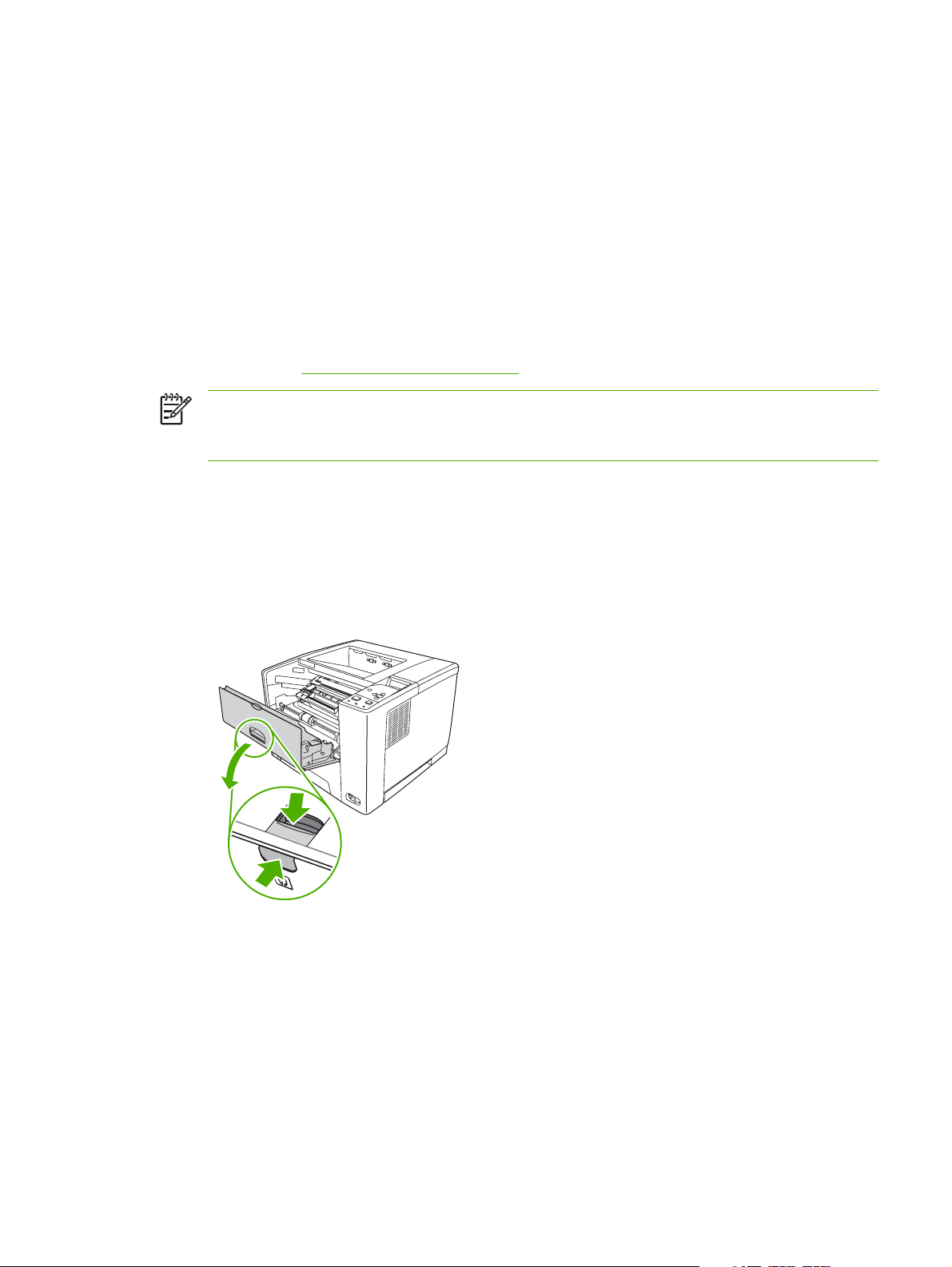
Install supplies
Carefully follow the guidelines in this section when replacing device supplies.
Supply replacement guidelines
To facilitate the replacement of supplies, keep the following guidelines in mind when setting up the
device.
Sufficient space is required above and in the front of the device for removing supplies.
●
The device should be located on a flat, sturdy surface.
●
For instructions on installing supplies, see the installation guides provided with each supply item or see
more information at
NOTE Hewlett-Packard recommends the use of HP products in this device. Use of non-
HP products may cause problems requiring service that is not covered by the HP warranty or
service agreements.
Change the print cartridge
When a print cartridge approaches the end of useful life, a message appears on the control panel
recommending that you order a replacement. The device can continue to print using the current print
cartridge until a message appears instructing you to replace the cartridge.
www.hp.com/support/LJP3005.
1. Open the cartridge door.
ENWW Install supplies 23
Page 37

2. Remove the used print cartridge from the device.
3. Remove the new print cartridge from the bag. Place the used print cartridge in the bag for recycling.
4. Grasp both sides of the print cartridge and distribute the toner by gently rocking the print cartridge.
CAUTION Do not touch the shutter or the surface of the roller.
5. Remove the shipping tape from the new print cartridge. Discard the shipping tape according to
local regulations.
24 Chapter 2 Installation and configuration ENWW
Page 38

6. Align the print cartridge with the tracks inside the device, and, using the handle, insert the print
cartridge until it is firmly seated, and then close the cartridge door.
After a short time, the control panel should display Ready.
7. Installation is complete. Place the used print cartridge in the box in which the new cartridge arrived.
See the enclosed recycling guide for recycling instructions.
8. If you are using a non-HP print cartridge, check the device control panel for further instructions.
For additional help, go to
www.hp.com/support/LJP3005.
ENWW Install supplies 25
Page 39
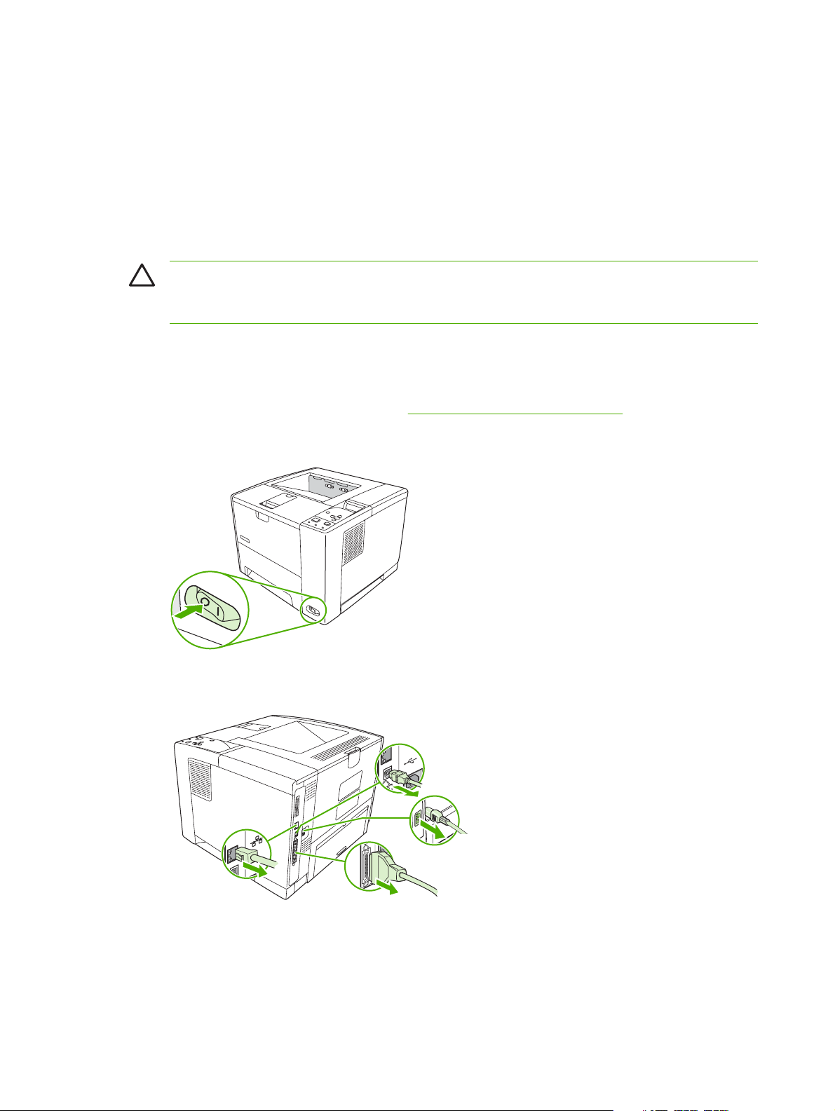
Install accessories
Install memory
You might want to add more memory to the device if you often print complex graphics, print PostScript
(PS) documents, or use many downloaded fonts. Added memory also gives you more flexibility in
supporting job-storage features, such as quick copying.
Install device memory
CAUTION Static electricity can damage DIMMs. When handling DIMMs, either wear an
antistatic wrist strap or frequently touch the surface of the DIMM antistatic package, then touch
bare metal on the device.
The HP LaserJet P3005 devices come with one DIMM slot. If desired, you can replace a DIMM installed
in the slot with a higher memory DIMM.
If you have not already done so, print a configuration page to find out how much memory is installed in
the device before adding more memory. See
1. After the configuration page has printed, turn the device off and disconnect the power cord.
Use information pages on page 38.
2. Disconnect all interface cables.
26 Chapter 2 Installation and configuration ENWW
Page 40
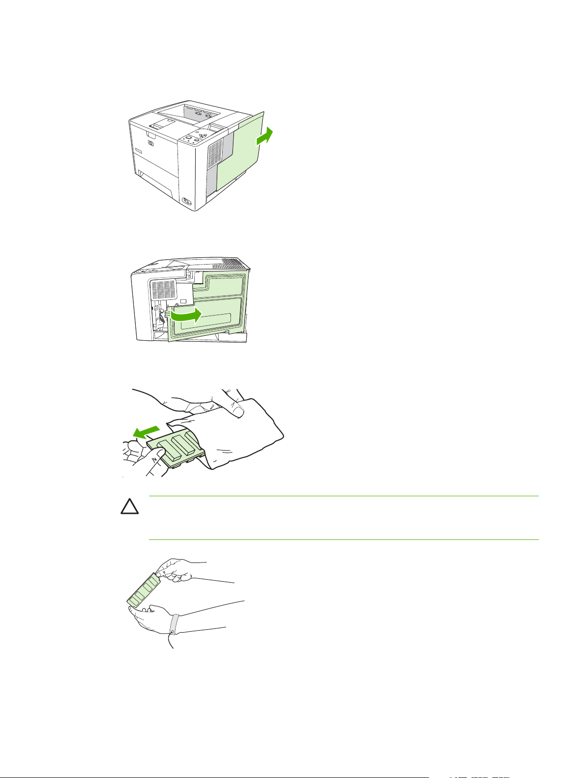
3. Remove the right side panel by sliding it towards the rear of the device until the side slides from
the device.
4. Open the access door by pulling on the metal tab.
5. Remove the DIMM from the antistatic package.
CAUTION To reduce the possibility of damage caused by static electricity, always wear
an electrostatic discharge (ESD) wrist strap or touch the surface of the antistatic package
before handling DIMMs.
ENWW Install accessories 27
Page 41

6. Hold the DIMM by the edges, and align the notches on the DIMM with the DIMM slot. (Check that
the locks on each side of the DIMM slot are open.)
7. Press the DIMM straight into the slot, and press firmly. Make sure the locks on each side of the
DIMM snap into place.
NOTE To remove a DIMM, first release the locks.
8. Close the access door, and press firmly until it snaps into place.
28 Chapter 2 Installation and configuration ENWW
Page 42
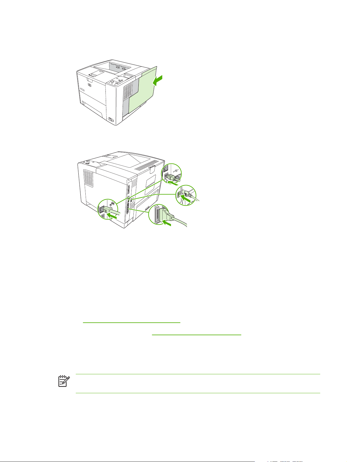
9. To replace the right side panel, line up the alignment arrows and slide the panel toward the front
of the device until it latches into place.
10. Reconnect the interface cable(s) and the power cord.
11. Turn the device on.
Check DIMM installation
After installing the DIMM, make sure that the installation was successful.
Verify that DIMM is installed correctly
1. Turn the device on. Check that the Ready light is illuminated after the device has gone through the
startup sequence. If an error message appears, a DIMM might have been incorrectly installed.
Control-panel messages on page 131.
See
2. Print a configuration page (see
3. Check the memory section on the configuration page and compare it to the configuration page that
was printed before the memory installation. If the amount of memory has not increased, the DIMM
might not be installed correctly, or the DIMM might be defective. Repeat the installation procedure.
If necessary, install a different DIMM.
NOTE If you installed a device language (personality), check the "Installed Personalities and
Options" section on the configuration page. This area should list the new device language.
Use information pages on page 38).
ENWW Install accessories 29
Page 43

Enable memory for Windows
1. On the Start menu, Settings, and Printers or Printers and Faxes.
2. Select this device and select Properties.
3. On the Configure tab, click More.
4. In the Total Memory field, type or select the total amount of memory that is now installed.
5. Click OK.
6. Go to
Check DIMM installation on page 29.
Use HP Jetdirect print server cards
Follow these procedures to install or remove an EIO card.
Install an HP Jetdirect print server card
1. Turn off the device.
2. Remove the two screws and cover plate from the EIO slot on the back of the device.
NOTE Do not discard the screws or the cover plate. Save them for future use if you remove
the EIO card.
30 Chapter 2 Installation and configuration ENWW
Page 44

3. Install the EIO card in the EIO slot and tighten the screws.
4. Connect the network cable to the EIO card.
5. Turn on the device, and then print a configuration page to verify that the new EIO device is
recognized. See
NOTE When you print a configuration page, an HP Jetdirect configuration page that contains
network configuration and status information also prints.
Use information pages on page 38.
Remove an HP Jetdirect print server card
1. Turn off the device.
2. Disconnect the network cable from the EIO card.
3. Loosen the two screws from the EIO card, and then remove the EIO card from the EIO slot.
4. Place the cover plate from the EIO slot onto the back of the device. Insert and tighten the two
screws.
5. Turn on the device.
ENWW Install accessories 31
Page 45

3 Maintenance
Chapter contents
Manage supplies
●
Clean the device
●
Management tools
●
ENWW Chapter contents 33
Page 46

Manage supplies
Using, storing, and monitoring the print cartridge can help ensure high-quality output.
Supplies life
The average cartridge yield is 6,500 pages (for the Q7551A cartridge) or 13,000 pages (for the Q7551X
cartridge), in accordance with ISO/IEC 19752. Actual cartridge yield depends on specific use.
CAUTION EconoMode is a feature that allows the device to use less toner per page. Selecting
this option may extend the life of the toner supply and may reduce cost per page. However, it will
also reduce print quality. The printed image is lighter, but it is adequate for printing drafts or proofs.
HP does not recommend full-time use of EconoMode. If EconoMode is used full-time, it is possible
that the toner supply will outlast the mechanical parts in the print cartridge. If print quality begins
to degrade under these circumstances, you will need to install a new print cartridge, even if there
may be toner supply remaining in the cartridge.
Approximate print-cartridge replacement intervals
Print cartridge Page count Approximate time period
Black (Q7551A) 6,500 pages
Black (Q7551X) 13,000 pages 6 months
1
Approximate life is based on 2,000 pages per month.
To order supplies online, go to
Manage the print cartridge
Print-cartridge storage
Do not remove the print cartridge from its package until you are ready to use it.
CAUTION To prevent damage to the print cartridge, do not expose it to light for more than a
few minutes.
Use genuine HP print cartridges
When you use a genuine new HP print cartridge, you can obtain the following supplies information:
Percentage of supplies remaining
●
1
www.hp.com/support/LJP3005 .
1
3 months
Estimated number of pages remaining
●
Number of pages printed
●
HP policy on non-HP print cartridges
Hewlett-Packard Company cannot recommend the use of non-HP print cartridges, either new or
remanufactured. Because they are not HP products, HP cannot influence their design or control their
quality.
34 Chapter 3 Maintenance ENWW
Page 47

NOTE Any damage caused by a non-HP print cartridge is not covered under the HP warranty
and service agreements.
To install a new HP print cartridge, see Change the print cartridge on page 23. To recycle the used
cartridge, follow the instructions included with the new cartridge.
Print-cartridge authentication
The device automatically authenticates the print cartridge when it is inserted into the device. During
authentication, the device notifies you whether a cartridge is a genuine HP print cartridge.
If the device control-panel message states that this is not a genuine HP print cartridge and you believe
you purchased an HP print cartridge, see
HP fraud hotline and Web site
Call the HP fraud hotline (1-877-219-3183, toll-free in North America) or go to www.hp.com/go/
anticounterfeit when you install an HP print cartridge and the control-panel message says the cartridge
is non-HP. HP will help determine if the cartridge is genuine and take steps to resolve the problem.
Your print cartridge might not be a genuine HP print cartridge if you notice the following:
You are experiencing a high number of problems with the print cartridge.
●
The cartridge does not look like it usually does (for example, the orange pull tab is missing, or the
●
packaging differs from HP packaging).
HP fraud hotline and Web site on page 35.
ENWW Manage supplies 35
Page 48

Clean the device
Over time, particles of toner and paper accumulate inside the device. This can cause print-quality
problems during printing. Cleaning the device eliminates or reduces these problems.
Clean the paper path and print-cartridge areas every time that you change the print cartridge or
whenever print-quality problems occur. As much as possible, keep the device from dust and debris.
Clean the exterior
Use a soft, damp, lint-free cloth to wipe dust, smudges, and stains off of the exterior of the device.
Clean the paper path
1. Press Menu.
2. Press
3. Press
4. Press to highlight CREATE CLEANING PAGE, and then press .
5. Remove all paper from tray 1.
6. Remove the cleaning page and load it face-down in tray 1.
7. At the device control panel, press to highlight PROCESS CLEANING PAGE, and then
press
to highlight CONFIGURE DEVICE, and then press .
to highlight PRINT QUALITY, and then press .
NOTE If your device has an automatic duplexer, go to step 7.
NOTE If you are not in the menus, navigate to PRINT QUALITY by using the previous
instructions.
.
Clean spilled toner
If you get any toner on your clothes or hands, wash them in cold water. Hot water will set the toner into
the fabric.
Clean the fuser
Run the device cleaning page to keep the fuser free of toner and paper particles that can sometimes
accumulate. Accumulation of toner and particles can cause specks to appear on the front or back side
of your print jobs.
To ensure optimum print quality, HP recommends that you use the cleaning page every time that you
replace the print cartridge.
The cleaning procedure takes about 2.5 minutes to complete. A CLEANING message appears on the
device control panel display while the cleaning is taking place.
In order for the cleaning page to work correctly, print the page on copier-grade paper (not bond, heavy,
or rough paper).
36 Chapter 3 Maintenance ENWW
Page 49

Create and use the cleaning page
1. If your device model includes a duplexer, open the rear output bin.
2. Press Menu to open the menus.
3. Use the
4. Use the
5. Use the
button or the button to scroll to CONFIGURE DEVICE, and then press .
button or the button to scroll to PRINT QUALITY, and then press .
button or the button to scroll to CREATE CLEANING PAGE, and then press .
6. Follow the instructions on the cleaning page to complete the cleaning process.
7. If your device model includes a duplexer, close the rear output bin.
ENWW Clean the device 37
Page 50

Management tools
Use information pages
From the device control panel, you can print pages that give details about the device and its current
configuration. The table below provides the procedures for printing the information pages.
Page description How to print the page
Menu map
Shows the control-panel menus and
available settings.
Configuration page
Shows device settings and installed
accessories.
Supplies status page
Shows print-cartridge toner levels.
1. Press Menu.
2.
Press
3.
If PRINT MENU MAP is not highlighted, press
and then press
The content of the menu map varies, depending on the options currently installed in
the device.
For a complete list of control panel menus and possible values, see the user guide.
1. Press Menu.
2.
Press
3.
Press
1. Press Menu.
2.
Press
3.
Press
to highlight INFORMATION, and then press .
or until it is highlighted,
.
to highlight INFORMATION, and then press .
to highlight PRINT CONFIGURATION, and then press .
NOTE If the device contains an HP Jetdirect print server or an optional hard
disk drive, an additional configuration page prints that provides information
about those devices.
to highlight INFORMATION, and then press .
to highlight PRINT SUPPLIES STATUS PAGE, and then press .
NOTE If you are using non-HP supplies, the supplies status page might not
show the remaining life for those supplies. For more information, see
HP policy on non-HP print cartridges on page 34.
Usage page
Shows a page count for each size of
paper printed, the number of one-sided
(simplexed) or two-sided (duplexed)
pages, and the average percentage of
coverage.
1. Press Menu.
2.
Press
3.
Press
to highlight INFORMATION, and then press .
to highlight PRINT USAGE PAGE, and then press .
38 Chapter 3 Maintenance ENWW
Page 51

Page description How to print the page
File directory
Shows information for all installed mass
storage devices.
PCL or PS font list
Shows which fonts are currently
installed in the device.
1. Press Menu.
2.
Press
3.
Press
NOTE This option does not appear if no mass storage devices are installed.
1. Press Menu.
2.
Press
3.
Press
then press
NOTE The font lists also show which fonts are resident on an optional hard
disk accessory or flash DIMM.
Use the HP Easy Printer Care software
The HP Easy Printer Care software is a program that you can use for the following tasks:
Check the device status.
●
Check supplies status.
●
to highlight INFORMATION, and then press .
to highlight PRINT FILE DIRECTORY, and then press .
to highlight INFORMATION, and then press .
to highlight PRINT PCL FONT LIST or PRINT PS FONT LIST, and
.
Set up alerts.
●
Gain access to problem-solving and maintenance tools.
●
You can use the HP Easy Printer Care software when the device is directly connected to your computer
or when it is connected to a network. You must perform a complete software installation to use the
HP Easy Printer Care software.
NOTE You do not have to have Internet access to open and use the HP Easy Printer Care
software. However, if you click a Web-based link, you must have Internet access to go to the site
associated with the link.
Open the HP Easy Printer Care software
Use one of the following methods to open HP Easy Printer Care software:
On the Start menu, select Programs, select Hewlett-Packard, and then select HP Easy Printer
●
Care software.
In the Windows system tray (in the lower-right corner of the desktop), double-click the HP Easy
●
Printer Care software icon.
Double-click the desktop icon.
●
ENWW Management tools 39
Page 52

HP Easy Printer Care software sections
Section Options
Device List tab
Shows information about
each device in the
Devices list
Support tab
Provides help information
and links
Supplies Ordering
window
Provides access to online
or e-mail supplies
ordering
Alert Settings window
Allows you to configure
the device to
automatically notify you
of device issues
Device information, including printer name, make, and model
●
An icon (if the View as drop-down box is set to Tiles, which is the default setting)
●
Any current alerts for the device
●
If you click a device in the list, the HP Easy Printer Care software opens the Overview tab for that
device.
Provides device information, including alerts for items needing attention.
●
Provides links to troubleshooting and maintenance tools.
●
Ordering list: Shows the supplies that you can order for each device. If you want to order a
●
certain item, click the Order check box for that item in the supplies list.
Shop Online for Supplies button: Opens the HP SureSupply Web site in a new browser
●
window. If you have checked the Order check box for any items, the information about those
items can be transferred to the Web site, where you will receive information on options for
purchasing your selected supplies.
Print Shopping List button: Prints the information for the supplies that have the Order check
●
box selected.
Alerts on or off: Activates or deactivates the alerts feature.
●
When alerts appear: Sets when you want alerts to appear—either when you are printing to
●
that particular device, or anytime there is a device event.
Alert event type: Sets whether you want alerts for only critical errors, or for any error, including
●
continuable errors.
Overview tab
Contains basic status
information for the device
Find Other Printers
window
Allows you to add more
printers to your printer list
Notification method: Sets what type of alert should appear (pop-up message or desktop alert).
●
Devices list: Shows the devices that you can select.
●
Device Status section: Shows device status information. This section will indicate device alert
●
conditions, such as an empty print cartridge. It also shows device-identification information,
control-panel messages, and print-cartridge levels. After you correct a problem with the device,
click the
Supplies Status section: Shows detailed supplies status, such as the percentage of toner
●
remaining in the print cartridge and the status of the media that is loaded in each tray.
Supplies Details link: Opens the supplies status page to view more detailed information about
●
device supplies, ordering information, and recycling information.
Clicking the Find Other Printers link in the Devices list opens the Find Other Printers window.
The Find Other Printers window provides a utility that detects other network printers so that you
can add them to the Devices list and then monitor those devices from your computer.
button to update the section.
40 Chapter 3 Maintenance ENWW
Page 53

Use the embedded Web server
NOTE When the device is directly connected to a computer, use the HP Easy Printer Care
software to view the device status.
View device control status information
●
Set the type of paper loaded in each tray
●
Determine the remaining life on all supplies and order new ones
●
View and change tray configurations
●
View and change the device control panel menu configuration
●
View and print internal pages
●
Receive notification of device and supplies events
●
View and change network configuration
●
View support content that is specific to the current state of the device
●
When the device is connected to the network, the embedded Web server is automatically available.
To use the embedded Web server, you must have Microsoft Internet Explorer 4 and later or Netscape
Navigator 4 and later. The embedded Web server works when the device is connected to an IP-based
network. The embedded Web server does not support IPX-based or AppleTalk device connections. You
do not need Internet access to open and use the embedded Web server.
Open the embedded Web server by using a network connection
1. In a supported Web browser on your computer, type the device IP address or host name in the
address/URL field. To find the IP address or host name, print a configuration page. See
information pages on page 38.
NOTE After you open the URL, you can bookmark it so that you can return to it quickly in
the future.
2. The embedded Web server has three tabs that contain settings and information about the device:
the Information tab, the Settings tab, and the Networking tab. Click the tab that you want to view.
Embedded Web server sections on page 41 for more information about each tab.
See
Embedded Web server sections
Tab or section Options
Information tab
Provides device, status, and
configuration information
Device Status: Shows the device status and shows the life remaining of HP supplies,
●
with 0% indicating that a supply is empty. The page also shows the type and size of
print paper set for each tray. To change the default settings, click Change
Settings.
Configuration Page: Shows the information found on the configuration page.
●
Supplies Status: Shows the life remaining of HP supplies, with 0 percent indicating
●
that a supply is empty. This page also provides supplies part numbers. To order new
supplies, click Order Supplies in the Other Links area on the left side of the window.
Use
ENWW Management tools 41
Page 54

Tab or section Options
Event log: Shows a list of all device events and errors.
●
Usage page: Shows a summary of the number of pages the device has printed,
●
grouped by size and type.
Device Information: Shows the device network name, address, and model
●
information. To change these entries, click Device Information on the Settings tab.
Control Panel: Shows messages from the device control panel, such as Ready
●
or Sleep mode on.
Print: Allows you to send print jobs to the device.
●
Settings tab
Provides the ability to configure the
device from your computer
Configure Device: Allows you to configure device settings. This page contains the
●
traditional menus found on devices using a control-panel display.
E-mail Server: Network only. Used in conjunction with the Alerts page to set up
●
incoming and outgoing e-mail, as well as to set e-mail alerts.
Alerts: Network only. Allows you to set up to receive e-mail alerts for various device
●
and supplies events.
AutoSend: Allows you to configure the device to send automated e-mails regarding
●
device configuration and supplies to specific e-mail addresses.
Security: Allows you to set a password that must be entered to gain access to the
●
Settings and Networking tabs. Enable and disable certain features of the
embedded Web server.
Edit Other Links: Allows you to add or customize a link to another Web site. This
●
link is displayed in the Other Links area on all embedded Web server pages.
Device Information: Allows you to name the device and assign an asset number to
●
it. Enter the name and e-mail address for the primary contact who will receive
information about the device.
Language: Allows you to determine the language in which to display the embedded
●
Web server information.
Date & Time: Allows time synchronization with a network time server.
●
Wake Time: Allows you to set or edit a wake time for the device.
●
NOTE The Settings tab can be password-protected. If this device is on a
network, always consult with the system administrator before changing settings
on this tab.
42 Chapter 3 Maintenance ENWW
Page 55

Tab or section Options
Networking tab
Provides the ability to change
network settings from your
computer
Other links
Contains links that connect you to
the Internet
Network administrators can use this tab to control network-related settings for the device
when it is connected to an IP-based network. This tab does not appear if the device is
directly connected to a computer, or if the device is connected to a network using anything
other than an HP Jetdirect print server.
HP Instant Support™: Connects you to the HP Web site to help you find solutions.
●
This service analyzes your device error log and configuration information to provide
diagnostic and support information specific to your device.
Order Supplies: Connects to the HP SureSupply Web site, where you will receive
●
information on options for purchasing original HP supplies, such as print cartridges
and paper.
Product Support: Connects to the support site for the device, from which you can
●
search for help regarding general topics.
Use HP Web Jetadmin software
NOTE The Networking tab can be password-protected.
NOTE You must have Internet access in order to use any of these links. If you
use a dial-up connection and did not connect when you first opened the
embedded Web server, you must connect before you can visit these Web sites.
Connecting might require that you close the embedded Web server and reopen
it.
HP Web Jetadmin is a Web-based software solution for remotely installing, monitoring, and
troubleshooting network-connected peripherals. The intuitive browser interface simplifies cross-platform
management of a wide range of devices, including HP and non-HP devices. Management is proactive,
allowing network administrators the ability to resolve issues before users are affected. Download this
free, enhanced-management software at
www.hp.com/go/webjetadmin_software.
To obtain plug-ins to HP Web Jetadmin, click plug-ins, and then click the download link that is next to
the name of the plug-in that you want. The HP Web Jetadmin software can automatically notify you
when new plug-ins are available. On the Product Update page, follow the directions to automatically
connect to the HP Web site.
If installed on a host server, HP Web Jetadmin is available to any client through a supported Web
browser, such as Microsoft Internet Explorer 6.0 for Windows or Netscape Navigator 7.1 for Linux.
Browse to the HP Web Jetadmin host.
NOTE Browsers must be Java-enabled. Browsing from an Apple PC is not supported.
Use the HP Printer Utility for Macintosh
Use the HP Printer Utility to configure and maintain a device from a Mac OS X computer.
ENWW Management tools 43
Page 56

Open the HP Printer Utility
Open the HP Printer Utility in Mac OS X V10.2
1. Open the Finder, and then click Applications.
2. Click Library, and then click Printers.
3. Click hp, and then click Utilities.
4. Double-click HP Printer Selector to open the HP Printer Selector.
5. Select the device that you want to configure, and then click Utility.
Open the HP Printer Utility in Mac OS X V10.3 or V10.4
1. In the Dock, click the Printer Setup Utility icon.
NOTE If the Printer Setup Utility icon does not appear in the Dock, open the Finder,
click Applications, click Utilities, and then double-click Printer Setup Utility.
2. Select the device that you want to configure, and then click Utility.
HP Printer Utility features
The HP Printer Utility consists of pages that you open by clicking in the Configuration Settings list.
The following table describes the tasks that you can perform from these pages.
Item Description
Configuration Page Prints a configuration page.
Supplies Status Shows the device supplies status and provides links for online supplies-ordering.
HP Support Provides access to technical assistance, online supplies ordering, online registration, and
recycling and return information.
File Upload Transfers files from the computer to the device.
Upload Fonts Transfers font files from the computer to the device.
Firmware Update Transfers updated firmware files from the computer to the device.
Duplex Mode Turns on the automatic two-sided printing mode.
Economode & Toner Density Turns on the Economode setting to conserve toner, or adjusts toner density.
Resolution Changes the resolution settings, including the REt setting.
Lock Resources Locks or unlocks storage products, such as a hard disk.
Stored Jobs Manages print jobs that are stored on the device hard disk.
Trays Configuration Changes the default tray settings.
IP Settings Changes the device network settings and provides access to the embedded Web server.
Bonjour Settings Provides the ability to turn on or off Bonjour support or change the device service name
that is listed on a network.
Additional Settings Provides access to the embedded Web server.
E-mail Alerts Configures the device to send e-mail notices for certain events.
44 Chapter 3 Maintenance ENWW
Page 57

4 Theory of operation
Chapter contents
Basic operation
●
Internal components
●
Timing
●
Print cartridge memory system
●
ENWW Chapter contents 45
Page 58

Basic operation
This chapter presents an overview of the relationships among major components in the device, and
includes a detailed discussion of the image-formation system. The following systems are discussed:
Formatter
●
Engine control unit
●
Laser/scanner system
●
Pickup/feed/delivery system
●
Image-formation system
●
Figure 4-1 Systems overview
Formatter
The formatter is responsible for the following actions:
●
●
●
●
Formatting and controlling copies
Receiving and processing print data from the computer interface
Monitoring the control panel and relaying device status information
Developing and coordinating data placement and timing with the print engine
46 Chapter 4 Theory of operation ENWW
Page 59

Engine control unit (ECU)
The ECU coordinates all device functions, according to commands that the formatter sends. It drives
the laser/scanner system, the image formation system, and the pickup/feed/delivery system.
The ECU contains the following components:
Engine controller PCA
●
Low-voltage PCA
●
Figure 4-2 Print engine general structure on page 47 shows the relationship of the ECU to the pickup/
feed/delivery system, the laser/scanner system, and the image-formation system.
control system circuit diagram on page 48 provides the ECU circuit diagram. Figure 4-4 Low-voltage
power supply circuit diagram on page 49 shows the low-voltage power supply circuit on the ECU.
Figure 4-3 Engine
Output bin
cS
resaL
doid
e
S
EGAMI
r
im gninna
ror
D
B
tiucric
rotom rennac
P
yramir
g
nigrahc
NOITAMROF
rello
r
METSYS
P
Rear
output bin
Fuser
Tray 2
tinu gninaelC
refsn
arT
gnigrahc
or
rell
tinu deef xelpuD
Tray 2
Figure 4-2 Print engine general structure
ECU
METSYS RENNACS/RESAL
gnipoleveD
tinu
-otoh
evitisnes
murd
tinu pukcip
n
ignE
rewoP
u
s
Tray 1 pickup unit
ACP
rellortnoc e
egatlov-hgiH
ACP ylpp
Tray 1
r
ettamroF
noitpO
DEEF/PUKCIP
METSYS
ENWW Basic operation 47
Page 60
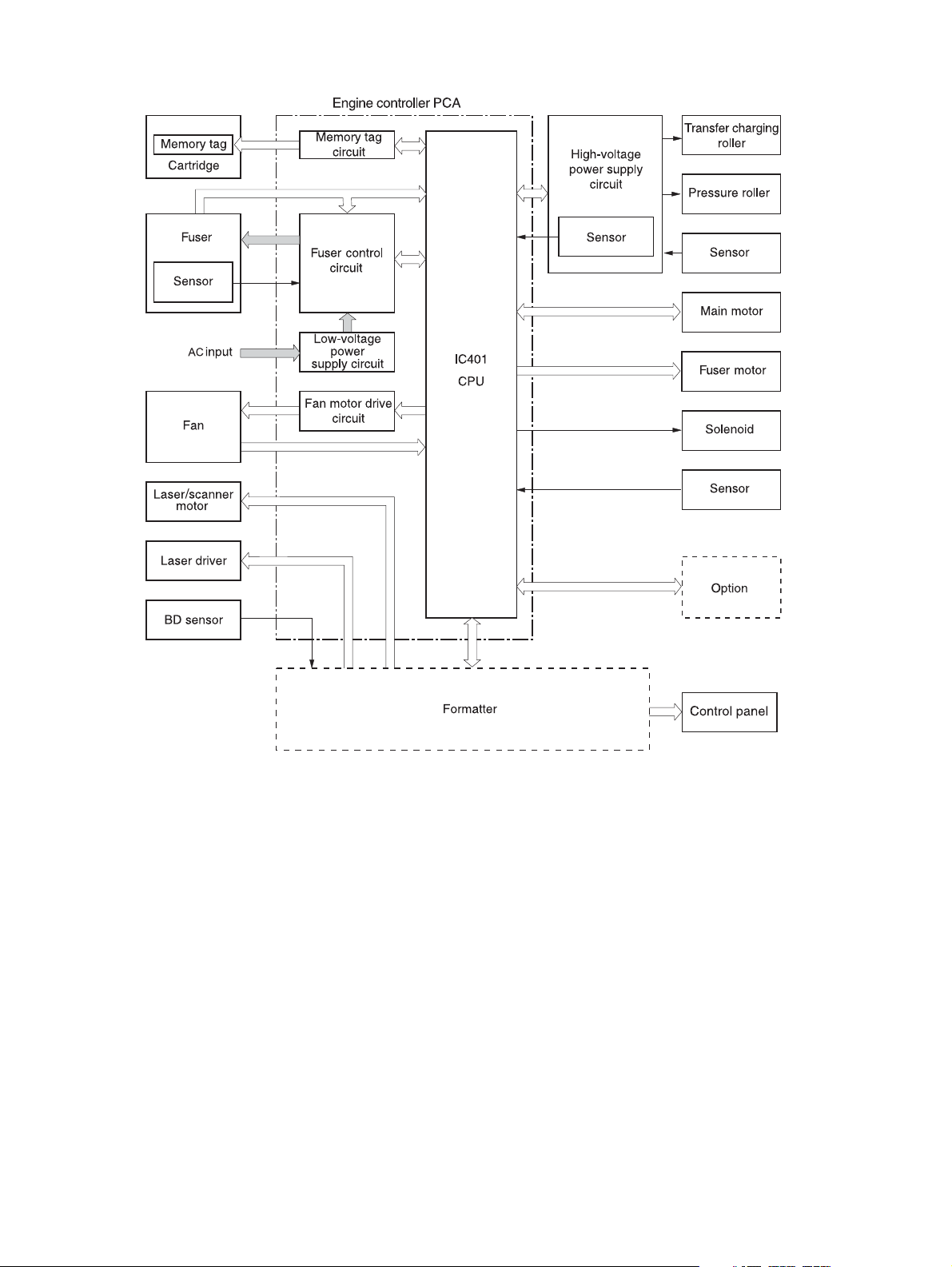
Figure 4-3 Engine control system circuit diagram
48 Chapter 4 Theory of operation ENWW
Page 61
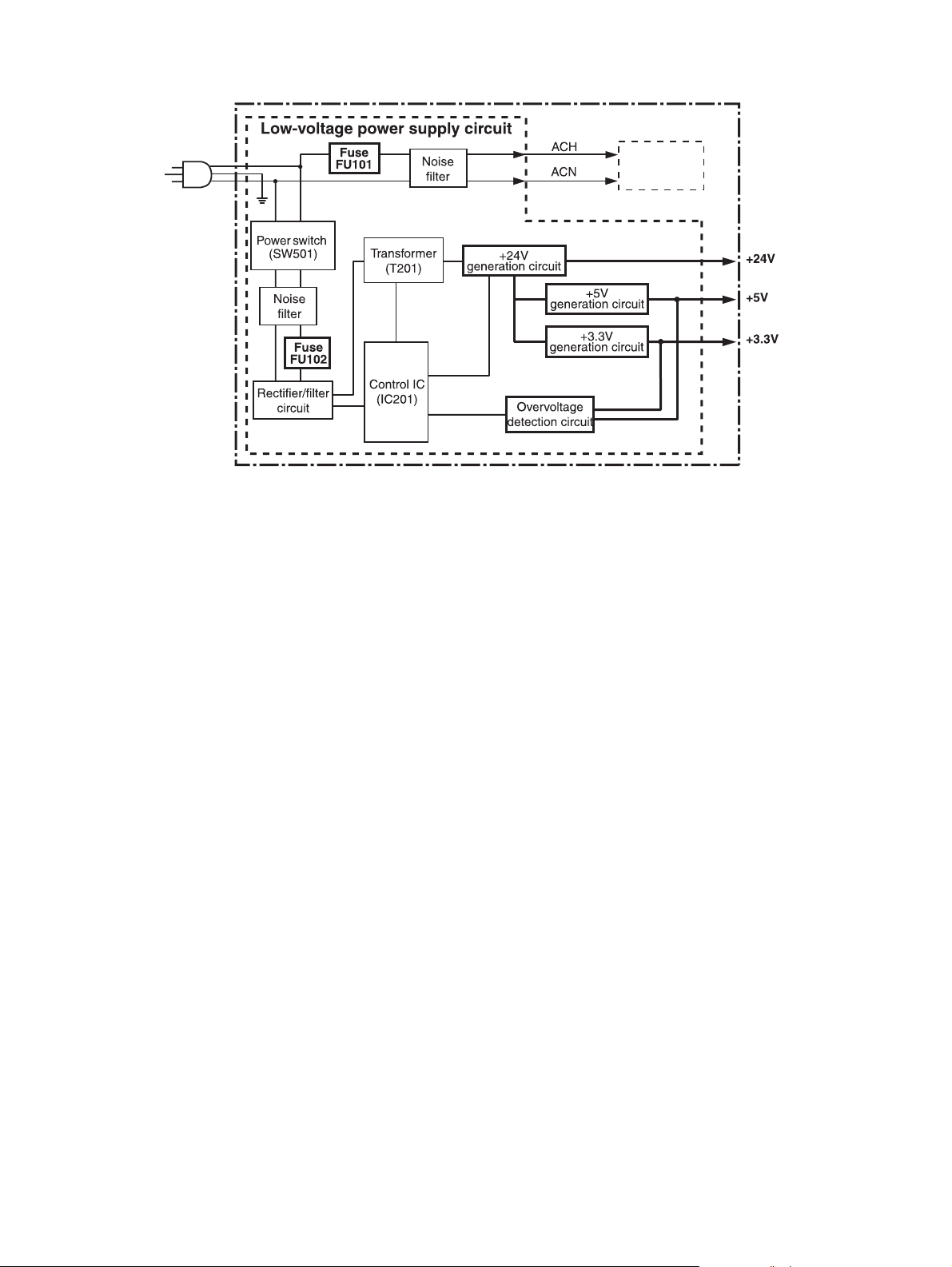
Figure 4-4 Low-voltage power supply circuit diagram
ECU
Fuser heater
control circuit
ENWW Basic operation 49
Page 62

Pickup/feed/delivery system
The pickup/feed/delivery system consists of several types of feed rollers and sensors. The ECU uses
two motors and two solenoids to drive the rollers. Three media-detection sensors detect media as it
passes through the device. If media does not reach or pass each sensor within a specified time period,
the ECU determines that a jam has occurred and alerts the formatter.
The following components are identified in
M1, main motor
●
M2, fuser motor
●
SL1, tray 1 pickup solenoid
●
SL2, tray 2 pickup solenoid
●
PS2, duplexer media-detection sensor
●
Figure 4-5 Pickup/feed/delivery system on page 50:
PS3, tray 2 media-detection sensor
●
PS901, top-of-page sensor
●
PS902, tray 1 media-detection sensor
●
SR1, top output-bin delivery flag
●
SR2, fuser-delivery flag
●
Figure 4-5 Pickup/feed/delivery system
50 Chapter 4 Theory of operation ENWW
Page 63

Laser/scanner system
The laser/scanner system receives video signals from the ECU and the formatter and converts the
signals into latent images on the photosensitive drum.
Figure 4-6 Laser/scanner system
ENWW Basic operation 51
Page 64

Image-formation system
Laser printing requires the interaction of several different technologies, including electronics, optics, and
electrophotographics, to provide a printed page.
Figure 4-7 Print cartridge diagram
Each process functions independently and must be coordinated with the other device processes. Image
formation consists of the following five processes:
Electrostatic latent-image formation
●
Developing
●
Transfer
●
Fusing
●
Drum cleaning
●
The five processes contain eight steps, which are shown in
on page 52 and described in the following sections.
Figure 4-8 Image-formation system
Figure 4-8 Image-formation system
52 Chapter 4 Theory of operation ENWW
Page 65

Step 1: Primary charging
DC and AC biases are applied to the primary charging roller, which transfers a uniform negative potential
to the photosensitive drum.
Figure 4-9 Primary charging
Step 2: Laser beam exposure
The laser beam scans the photosensitive drum to neutralize negative charges on parts of the drum. An
electrostatic latent image is formed on the drum where negative charges were neutralized.
Step 3: Developing
The developing cylinder comes in contact with the photosensitive drum to deposit toner onto the
electrostatic latent image.
NOTE The charges on the exposed area of the drum are shown as positive in Figure 4-10
Developing on page 53. The charges are actually negative, but they are more positive than the
charges on the developing cylinder.
Figure 4-10 Developing
ENWW Basic operation 53
Page 66
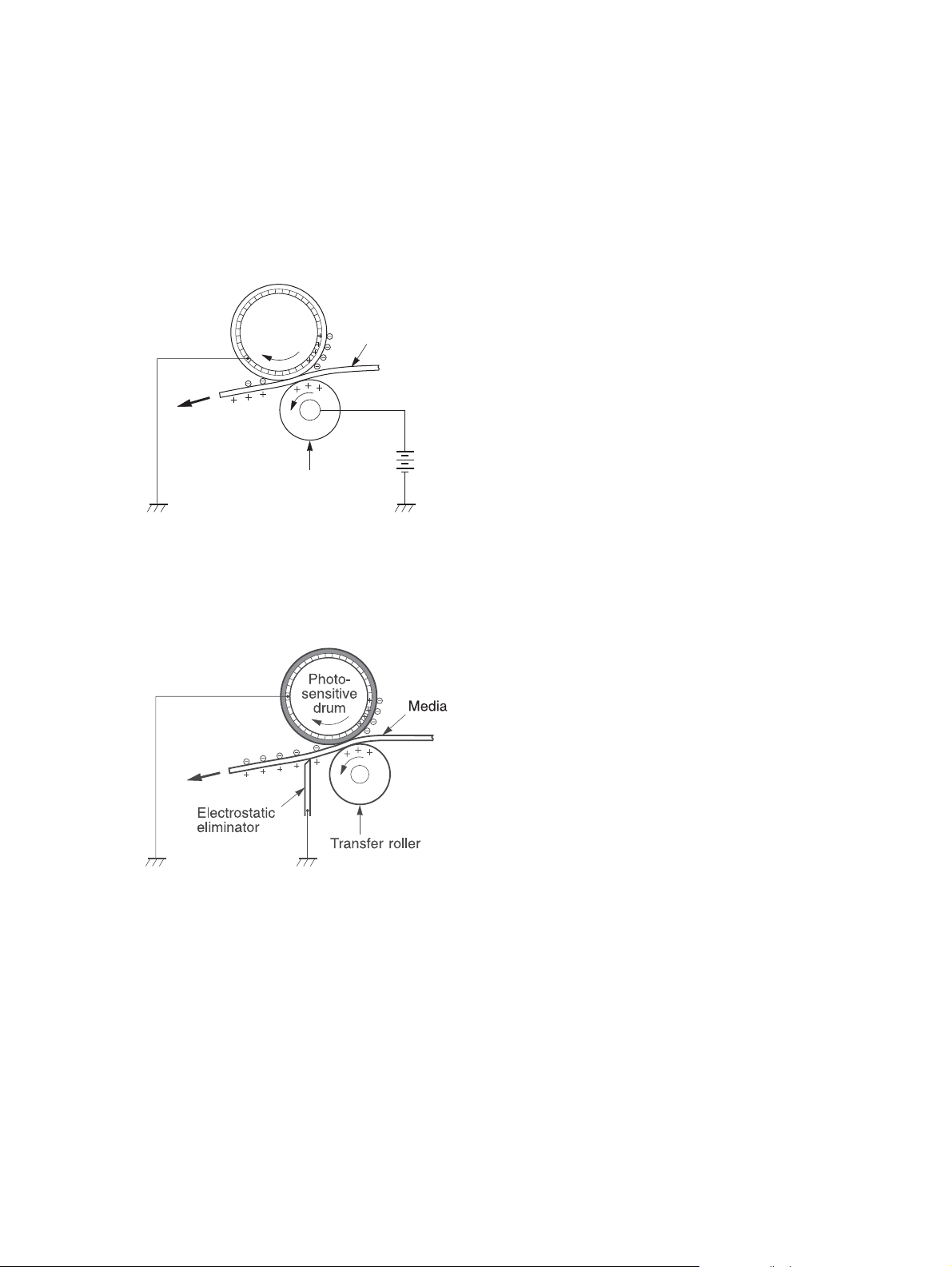
Toner acquires a negative charge through friction from the developing cylinder and the blade. When the
negatively charged toner comes in contact with the drum, the toner adheres to the electrostatic latent
image. The image on the drum becomes visible because of the toner.
Step 4: Transfer
The transfer charging roller, to which a DC positive bias is applied, imparts a positive charge on the print
media. When the print media comes in contact with the photosensitive drum, the toner is transferred to
the print media.
Figure 4-11 Transfer
Photo-
sensitive
drum
Transfer roller
Media
Step 5: Separation
The elasticity of the print media causes its separation from the photosensitive drum. A static charge
eliminator aids separation by weakening any electrostatic adhesion.
Figure 4-12 Separation
Step 6: Fusing
The DC negative bias applied to the fusing film strengthens the holding force of the toner on the print
media and prevents the toner from scattering.
54 Chapter 4 Theory of operation ENWW
Page 67

Figure 4-13 Fusing
Step 7: Drum cleaning
The cleaning blade scrapes the residual toner off of the photosensitive drum and deposits it into the
waste toner case.
Figure 4-14 Drum cleaning
ENWW Basic operation 55
Page 68

Internal components
Figure 4-15 Cross-section of device on page 56 highlights the major internal components.
1 2 3 4 5 6 7 8
9101112131415161718
Figure 4-15 Cross-section of device
1 Top output-bin delivery roller
2 Fuser roller, fuser assembly
3 Laser/scanner
4 Photosensitive drum, print cartridge
5 Print cartridge
6 Registration assembly
7 Tray 1 pickup roller
56 Chapter 4 Theory of operation ENWW
Page 69

8 Tray 1 separation pad
9 Feed roller
10 Tray 2 separation pad
11 Tray 2 pickup roller
12 Duplex pickup roller
13 Feed roller, registration assembly
14 Transfer roller
15 Oblique roller
16 Duplex feed roller
17 Fuser pressure roller, fuser assembly
18 Fuser delivery roller, fuser assembly
ENWW Internal components 57
Page 70

Timing
The microprocessor on the engine control unit (ECU) controls the device operation sequences. Table
4-1 Operation sequences on page 58 describes engine operations for each period of a print
operation.
Table 4-1 Operation sequences
Name Timing Purpose
Table 4-2 Power-on sequence on page 58 describes each step of the power-on sequence.
WAIT From power-on until the end of the main motor initial
drive
STBY (standby) From the end of the WAIT or LSTR period until either
a print command is sent from the formatter or the
power is turned off.
INTR (initial
rotation)
PRINT From the end of the INTR period until the top-of-page
LSTR (last
rotation)
From the time of the print command until the pickup
solenoid is turned on.
sensor detects the trailing edge of the media.
From the end of the PRINT period until the main
motor stops rotating.
Table 4-2 Power-on sequence
Step Action
Detects presence of a print cartridge. Clears potential
from the drum surface and cleans the transfer roller.
See
Table 4-2 Power-on sequence on page 58 for
a complete description of the WAIT (power-on)
period. Also see Figure 4-17 Timing diagram
on page 60 for detailed information about device
timing.
Prepares the device to receive print commands
Prepares the photosensitive drum for printing.
Forms the image on the photosensitive drum and
transfers the toner image to the media.
Delivers the last page of a print job.
After LSTR, the device either returns to STBY or, if
another print command was sent from the formatter,
enters INTR.
1 Power-on
2 CPU initialization
3 Video-interface communication start
4 Sensors check for residual media
5 Main motor initial drive
6 Fuser heater initial drive. The fuser heater reaches a surface temperature of 120°C.
7 Fuser-motor initial drive
8 Laser/scanner-motor initial drive
9 High-voltage control
Detection of the presence of a print cartridge
Cleaning of the transfer roller after the primary charging AC bias is turned on
10 Failure/abnormality check: detection of laser/scanner failure, fuser failure, and open covers
11 Communication with the memory tag
58 Chapter 4 Theory of operation ENWW
Page 71

W
NO rew
ezilaitinI
tia
P
o
eruliaF
D
nepo roo
Figure 4-16 Operational sequences
ybdnatS
i
tn
rP
maJ
ENWW Timing 59
Page 72

STBY
(Unit:Seconds)
1.43
LSTR
0.8
0.27
0.23
0.34
0.47
0.23
PRINT
INTR
STBY
WAIT
120°C Control
0.2
120°C Control
0.2
About 0.44
1.5
About 6.2
0.16
0.23
0.16
0.78
About 1.5
Forced emission
Negative Bias
About 1.2
About 0.7
About 0.4
About 1.46
About 1.39
About 1.05
3.0
3.9
3.7
3.2
0.7
0.5
0.5
0.09
0.23
0.09
About 7.4
About 0.22
About 0.22
About 3.3
Power Switch ON
SEQUENCE
Delivery Sensor (PS803)
Top of Page Sensor (PS801)
Paper Feeder Pickup Solenoid (SL3)
Tray 1 Pickup Solenoid (SL2)
Cassette Pickup Solenoid (SL1)
Scanner Motor(M3)
Fuser Motor (M2)
Fuser Heater (H1)
Main Motor (M1)
Print Command
2
1
8
7
6
5
4
3
Primary Charging Bias (AC)
Primary Charging Bias (DC)
9
10
Developing Bias (AC)
11
13
12
Developing Bias (DC)
14
Transfer Charging Bias
15
Laser Diode
16
LASER BEAM signal (BD)
17
20
19
18
Figure 4-17 Timing diagram
60 Chapter 4 Theory of operation ENWW
Page 73

Print cartridge memory system
The memory tag is a nonvolatile memory built into the print cartridge. The cartridge usage condition is
detected as the engine controller reads or writes the data stored on the memory tag. The engine
controller renews the information in the prescribed timing and reads or writes it from or to the memory
tag.
The engine controller commands the memory tag to read or write with the following conditions:
Read
●
Power is on.
●
The cartridge door is closed.
●
A command has been received from the formatter.
●
Write
●
A page of media is printed.
●
A command has been received from the formatter.
●
When the engine controller fails to read or write three times in a row, it determines that the memory tag
is abnormal and sends a cartridge memory abnormality warning to the formatter.
Figure 4-18 Print cartridge memory tag
ENWW Print cartridge memory system 61
Page 74

5 Removal and replacement
Chapter contents
Overview
●
Service approach
●
Covers
●
Control panel
●
Formatter
●
Fuser
●
Laser/scanner
●
Engine control unit (ECU)
●
Access plate
●
High-voltage power supply
●
Paper feed guide assembly
●
Main motor
●
Gear assembly
●
Reinstallation notes for the gear assembly
●
Tray 1 solenoid
●
Tray 2 solenoid
●
E-label reader (memory tag)
●
Face-down-roller shaft
●
Cartridge door
●
Transfer roller
●
Registration assembly
●
Tray 1 pickup roller
●
Tray 2 pickup roller
●
ENWW Chapter contents 63
Page 75

Separation pad
●
64 Chapter 5 Removal and replacement ENWW
Page 76

Overview
This chapter documents removal and replacement of field replaceable units (FRUs) only.
Removal and replacement strategy
Replace parts in the reverse order of their removal. Directions for difficult or critical replacement
procedures are included.
WARNING! The sheet-metal edges of the device can be sharp. Use caution when working on
the device.
NOTE Note the length, diameter, color, type, and location of each screw. Be sure to return each
screw to its original location during reassembly.
Incorrectly routed or loose cables can interfere with other internal components and can become
damaged or broken. Frayed or pinched cables can be difficult to locate. When reconnecting the
cables, always use the provided wire loops, lance points, or cable guides.
Electrostatic discharge
CAUTION The device contains parts that are sensitive to electrostatic discharge (ESD). Always
service the device at an ESD-protected workstation, or use an ESD mat.
Watch for the ESD symbol (shown below) to identify the parts that are sensitive to ESD. Protect these
parts by using an ESD wrist strap and by placing ESD-sensitive parts into protective ESD pouches.
Required tools
The following tools are needed to service this device:
#2 Phillips screwdriver with magnetic tip
●
Small flatblade screwdriver
●
Small needle-nose pliers
●
ESD mat
●
Penlight
●
CAUTION A pozidriv screwdriver will damage screw heads on the device. Use a #2 Phillips
screwdriver.
If you use a multispeed screwdriver, use a torque limiter.
ENWW Overview 65
Page 77

Types of screws
Illustration Description Size Part number Use
Screw with washer M3X8 XA9–1420–000CN Used to secure metal
components to metal
components (for
example, a ground wire
to the frame)
Screw, RS M3X6
M3X10
Screw, tapping M3X6 XA9–1503–000CN
Screw M3X8 XA9–1686–000CN
Screw P-M3X8 XB4–5300–807CN
Screw, tapping, truss
head
M4X10 XB4–7401–005CN Used to secure
XA9–1499–000CN Used to secure metal to
metal
anything to plastic
66 Chapter 5 Removal and replacement ENWW
Page 78

Service approach
Device repair normally begins by using the device internal diagnostics and the following two-step
process:
1. Isolate the problem to the major system (for example, the network or server, or the device).
2. Troubleshoot the problem by using the procedures in chapter 6.
After you locate a faulty part, the device can usually be repaired at the assembly level by replacing fieldreplaceable units (FRUs). Some mechanical assemblies might need to be repaired at the subassembly
level. Hewlett-Packard Company does not support replacement of components on the printed circuit
assembles.
Before performing service
Follow the pre-service procedures before you perform service.
Pre-service procedures
1. Remove all media from the device.
2. Unplug the power cord and the interface cable.
3. Lift the device off of any installed optional trays.
4. Remove the print cartridge.
5. Remove tray 2.
6. Place the device on an ESD mat. If an ESD mat or an ESD-protected workstation is not available,
discharge body static and ground the device chassis before servicing the device.
ENWW Service approach 67
Page 79

Parts removal order
Use the following diagram to determine which parts must be removed before removing other parts.
Back cover
Fuser
I/O cover
Right side cover
Top, right cover
Front, right cover
Left side cover
Top cover
Laser/scanner assembly
Control panel
Fan, right side
ECU
Main gear assembly
Fuser
Duplex access plate
High-voltage power supply
Paper feed guide assembly
Main motor
Figure 5-1 Parts removal diagram
After performing service
Reinstall the print cartridge.
●
Reinstall tray 2.
●
Return all media to the trays.
●
Plug in the power cable and turn on the device.
●
68 Chapter 5 Removal and replacement ENWW
Page 80

Covers
Not all covers have to be removed to get to various FRUs. See Parts removal order on page 68 if you
are unsure about which covers must be removed.
Right-side cover
1. Slide the right-side cover toward the back of the device to disengage it from the front, right cover
and the right-side handle.
Figure 5-2 Removing the right-side cover
2. Lift the cover away from the device.
ENWW Covers 69
Page 81

Left-side cover
1. Remove two screws (callout 1).
1
Figure 5-3 Removing the left-side cover (1 of 2)
2. Open the rear output bin door.
70 Chapter 5 Removal and replacement ENWW
Page 82

3. Release one tab (callout 2) at the back of the device by pressing the tab through a hole in the
chassis toward the rear of the device, and then rotate the cover away from the device at the back
of the device.
2
Figure 5-4 Removing the left-side cover (2 of 2)
4. Lift the cover up slightly, slide it toward the front of the device to clear tabs at the front, and then
lift the cover away from the device.
ENWW Covers 71
Page 83

Back cover
1. Open the rear output bin door all the way, press the door down to disengage two door-stops (callout
1), and then remove two screws (callout 2).
2
1
2. Lift the bottom of the cover first to disengage the alignment tabs at the top of the back cover, and
I/O cover
1. Remove the back cover. See Back cover on page 72.
Figure 5-5 Removing the back cover
then lift the cover away from the device.
72 Chapter 5 Removal and replacement ENWW
Page 84

2. Rotate the I/O cover to clear tabs at the right side of the cover.
Figure 5-6 Removing the I/O cover
3. Lift the cover off of the device.
Top, right cover
1. Remove the following components:
Right-side cover (see
●
Back cover (see
●
I/O cover (see
●
Right-side cover on page 69)
Back cover on page 72)
I/O cover on page 72)
ENWW Covers 73
Page 85

2. Remove one screw (callout 1) on the right side at the back of the device.
1
3. Slide the cover to the rear, and then lift the cover off of the device.
Top cover
1. Remove the following components:
2. Open the cartridge door.
Figure 5-7 Removing the top, right cover
Right-side cover (see
●
Left-side cover (see
●
Back cover (see
●
Top, right cover (see
●
Right-side cover on page 69)
Left-side cover on page 70)
Back cover on page 72)
Top, right cover on page 73)
74 Chapter 5 Removal and replacement ENWW
Page 86

3. Remove four screws (callout 1).
1
2
Figure 5-8 Removing the top cover
4. Lift the cover off of the device.
Front, right cover
1. Remove the following components:
Right-side cover (see
●
Formatter cover (see
●
Right-side cover on page 69)
Formatter on page 80)
ENWW Covers 75
Page 87

2. Remove two screws (callout 1).
1
Figure 5-9 Removing the front, right cover (1 of 2)
76 Chapter 5 Removal and replacement ENWW
Page 88

3. Rotate the cover to clear two tabs (callout 2) at the front of the device.
2
Figure 5-10 Removing the front, right cover (2 of 2)
4. Rotate the cover away from the device.
ENWW Covers 77
Page 89

Control panel
1. Remove the following components:
Right-side cover (see
●
Top, right cover (see
●
Front, right cover (see
●
2. Remove the grounding wire over the fan assembly (callout 1), disconnect one cable (callout 2) on
the formatter, and then remove one grounding screw (callout 3).
Right-side cover on page 69)
Top, right cover on page 73)
Front, right cover on page 75)
1
2
3
Figure 5-11 Removing the control panel
3. Lift the control panel off of the device.
Reinstallation tip To reinstall the control panel correctly, use the locator pin (callout 4) and
place the sheet metal front of the control panel assembly (callout 5) in front of the device chassis.
78 Chapter 5 Removal and replacement ENWW
Page 90

4
Figure 5-12 Reinstalling the control panel
5
ENWW Control panel 79
Page 91

Formatter
1. Remove the right-side cover. See Right-side cover on page 69.
2. Open the formatter cover, and then lift the cover off of the hinges (callout 1) at the back of the cover.
1
Figure 5-13 Removing the formatter (1 of 3)
80 Chapter 5 Removal and replacement ENWW
Page 92
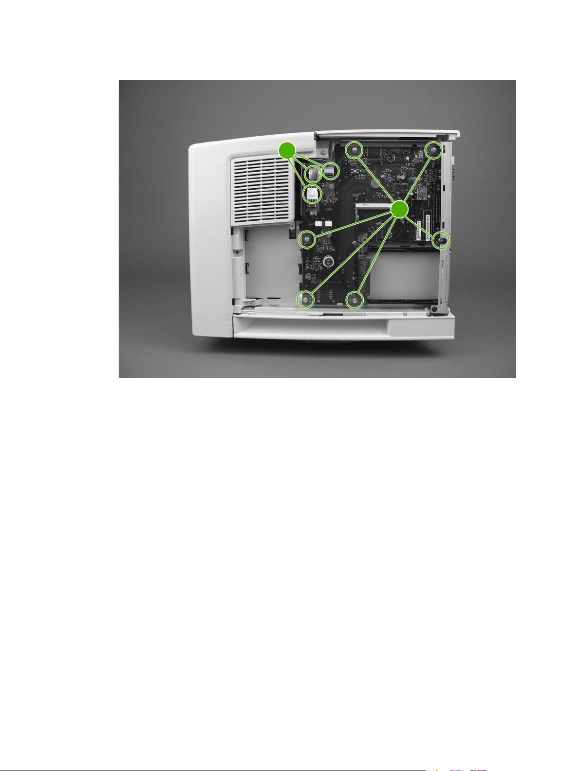
3. Disconnect three cables (callout 2), and then remove six screws (callout 3).
2
3
Figure 5-14 Removing the formatter (2 of 3)
ENWW Formatter 81
Page 93

4. Pull the left side of the formatter out slightly, and then slide it toward the front of the device.
Figure 5-15 Removing the formatter (3 of 3)
82 Chapter 5 Removal and replacement ENWW
Page 94

Fuser
1. Remove the following components:
Back cover (see
●
I/O cover (see
●
2. Remove the duplexer inlet guide by releasing two tabs (callout 1) on the guide, and then sliding
the guide toward the back of the device.
Back cover on page 72)
I/O cover on page 72)
1
Figure 5-16 Removing the fuser (1 of 3)
Reinstallation tip Make sure that both tabs snap back into place when reinstalling the
duplexer inlet guide.
ENWW Fuser 83
Page 95

3. Disconnect two cables at the right, inside, of the device (callout 2), and then disconnect the fuser
power cable at the left side of the device (callout 3).
3
2
Figure 5-17 Removing the fuser (2 of 3)
84 Chapter 5 Removal and replacement ENWW
Page 96

4. Remove three self-tapping screws (callout 4) and one grounding screw (callout 5).
4
5
Figure 5-18 Removing the fuser (3 of 3)
5. Tilt the fuser slightly toward the back of the device, and then slide the fuser out of the back of the
device.
ENWW Fuser 85
Page 97

Laser/scanner
1. Remove all covers (see Covers on page 69).
2. Release one tab (callout 1) on the air duct, and then lift the air duct out of the device.
1
Figure 5-19 Removing the laser/scanner (1 of 2)
86 Chapter 5 Removal and replacement ENWW
Page 98
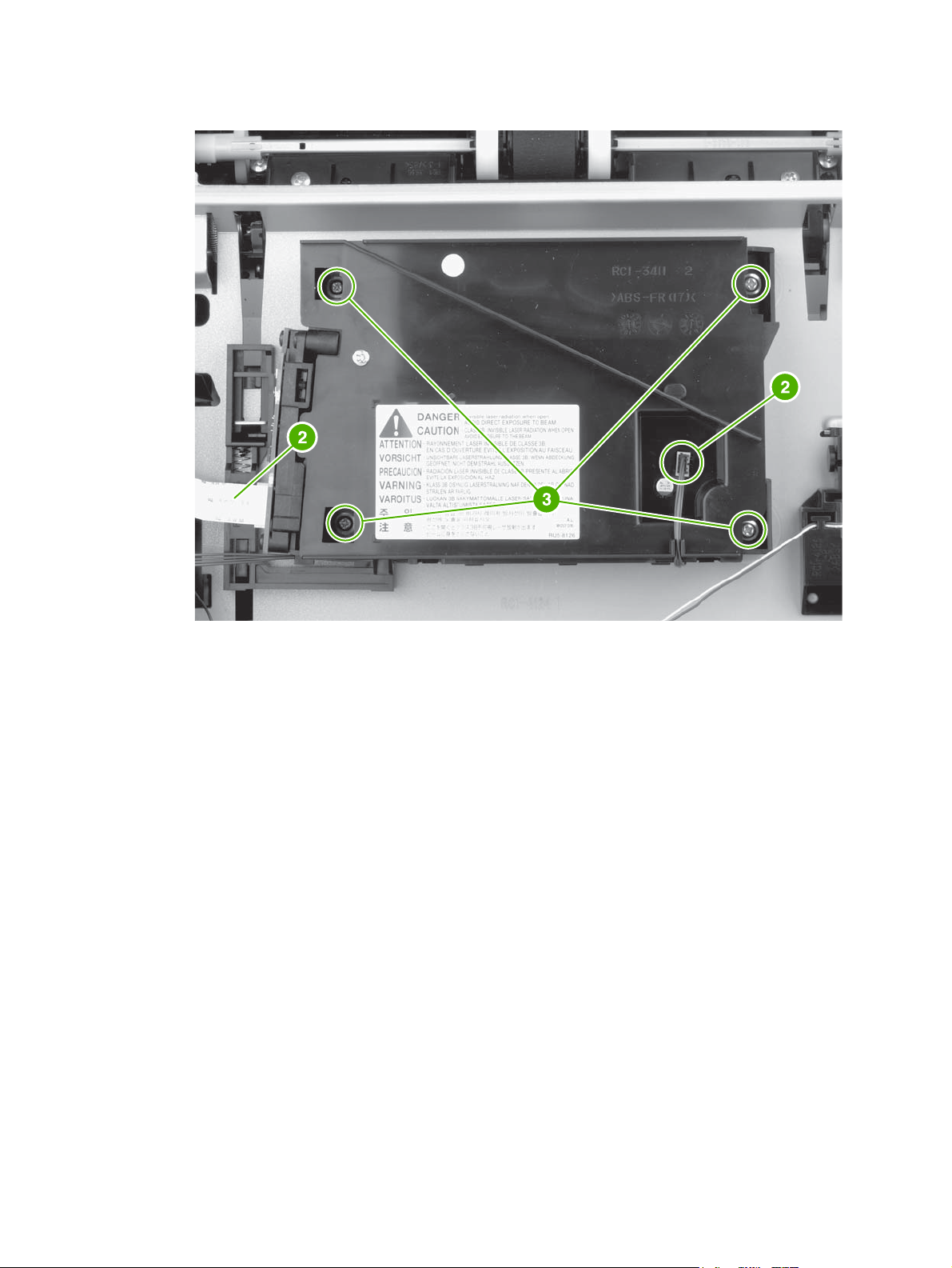
3. Disconnect two cables (callout 2) and then remove four screws (callout 3).
Figure 5-20 Removing the laser/scanner (2 of 2)
4. Lift the laser/scanner out of the device.
ENWW Laser/scanner 87
Page 99

Engine control unit (ECU)
1. Remove the following components:
All covers (see
●
Control panel (see
●
Formatter (see
●
2. Remove the two screws (callout 1) on the fan assembly, disconnect the fan cable from the ECU,
and then remove the fan assembly.
Covers on page 69)
Control panel on page 78 )
Formatter on page 80)
1
Figure 5-21 Removing the ECU (1 of 8)
88 Chapter 5 Removal and replacement ENWW
Page 100
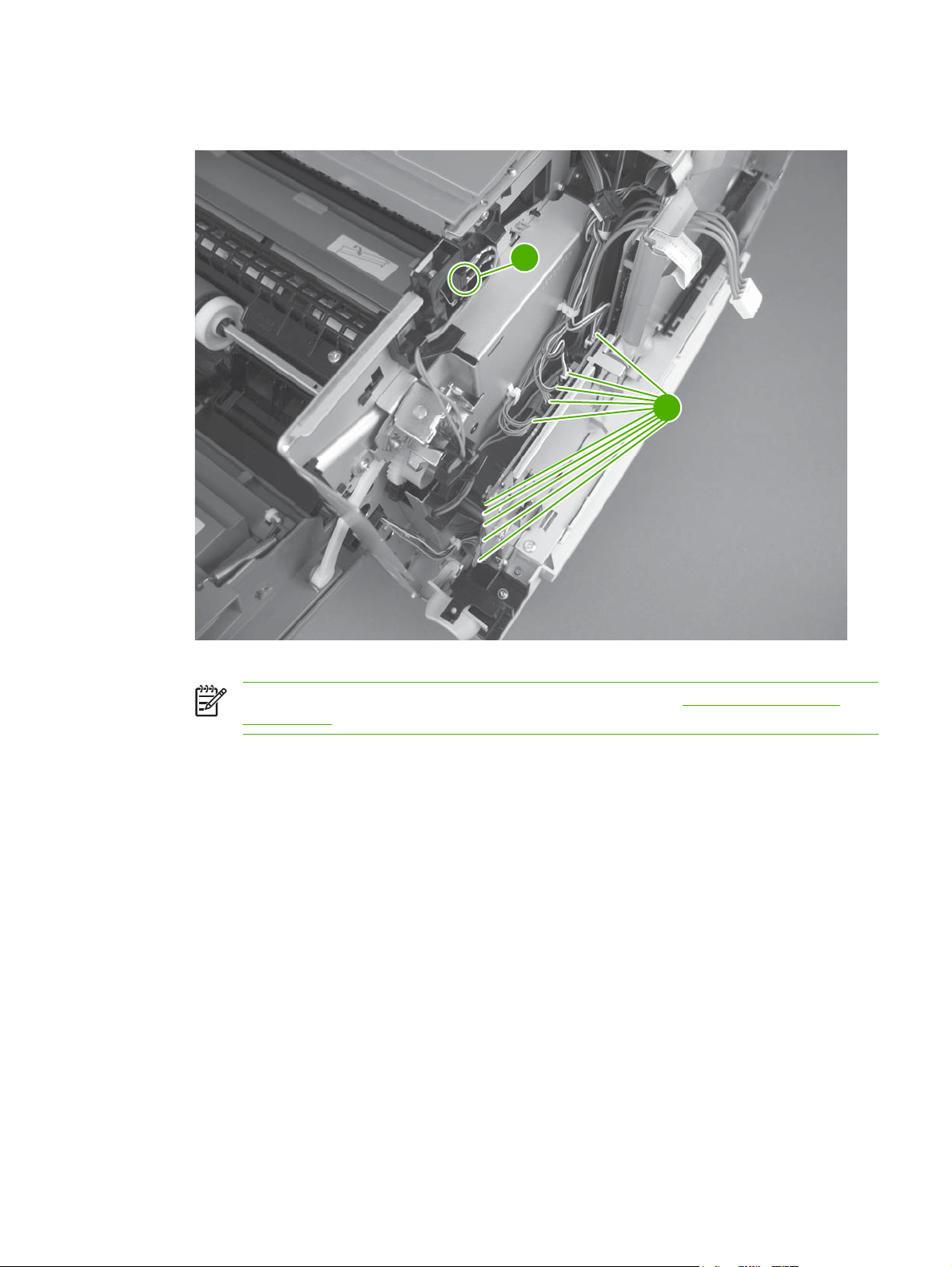
3. Disconnect 10 cables (callout 2) from the ECU, and then disconnect and unroute the cartridge-
door switch and wires (callout 3).
3
2
Figure 5-22 Removing the ECU (2 of 8)
NOTE For more information about the ECU connectors, see Figure 6-9 ECU wiring
on page 195.
ENWW Engine control unit (ECU) 89
 Loading...