

Page 1
LASERJET ENTERPRISE MFP M725
Repair Manual
M725zM725dn M725f M725z+
Page 2

Page 3

HP LaserJet Enterprise MFP M725
Repair Manual
Page 4

Copyright and License
Trademark Credits
© 2013 Copyright Hewlett-Packard
Development Company, L.P.
Reproduction, adaptation, or translation
without prior written permission is
prohibited, except as allowed under the
copyright laws.
The information contained herein is subject
to change without notice.
The only warranties for HP products and
services are set forth in the express warranty
statements accompanying such products and
services. Nothing herein should be
construed as constituting an additional
warranty. HP shall not be liable for technical
or editorial errors or omissions contained
herein.
Part number: CF066-90988
Edition 1, 03/2013
Microsoft®, Windows®, Windows® XP,
and Windows Vista® are U.S. registered
trademarks of Microsoft Corporation.
Page 5

Conventions used in this guide
TIP: Tips provide helpful hints or shortcuts.
NOTE: Notes provide important information to explain a concept or to complete a task.
CAUTION: Cautions indicate procedures that you should follow to avoid losing data or damaging
the product.
WARNING! Warnings alert you to specific procedures that you should follow to avoid personal
injury, catastrophic loss of data, or extensive damage to the product.
ENWW iii
Page 6

iv Conventions used in this guide ENWW
Page 7

Table of contents
1 Removal and replacement ................................................................................................ 1
Removal and replacement strategy ............................................................................................. 2
Introduction .............................................................................................................. 2
Required tools ........................................................................................................... 3
Types of screws ........................................................................................................ 3
Service approach ...................................................................................................... 3
Before performing service .......................................................................................... 4
After performing service ............................................................................................. 4
Parts removal order ................................................................................................... 4
Pickup rollers ........................................................................................................................... 5
Tray 1 (multipurpose tray) pickup roller ........................................................................ 5
Reinstall the Tray 1 (multipurpose tray) pickup roller ....................................... 6
Tray 2 and Tray 3 pickup rollers ................................................................................. 7
Tray 4, Tray 5, and Tray 6 pickup and feed rollers ....................................................... 9
High capacity input feeder (HCI) pickup, feed, and separation rollers ............................ 11
Document feeder pickup and feed roller assembly ....................................................... 13
Separation pads and rollers .................................................................................................... 15
Tray 1 separation pad assembly ............................................................................... 15
Tray 2 and Tray 3 separation rollers .......................................................................... 16
Tray 4, 5, and 6 separation rollers ............................................................................ 17
Document feeder separation pad .............................................................................. 18
Reinstall the document feeder separation pad .............................................. 19
Covers and doors .................................................................................................................. 21
Front cover ............................................................................................................. 21
Right rear cover ...................................................................................................... 22
Left door ................................................................................................................ 23
Rear cover ............................................................................................................. 24
Front left lower cover ............................................................................................... 25
Front right lower cover ............................................................................................. 26
Face-down cover ..................................................................................................... 27
Tray 1 (multipurpose tray) cover ................................................................................ 28
Right door .............................................................................................................. 29
ENWW v
Page 8

Reinstall the right door .............................................................................. 30
Left handle cover ..................................................................................................... 31
Left inner lower cover .............................................................................................. 32
Left inner rear cover ................................................................................................. 33
Left inner front cover ................................................................................................ 35
Right handle cover .................................................................................................. 37
Face-down side cover .............................................................................................. 38
Front upper cover .................................................................................................... 39
Top rear outer cover ................................................................................................ 40
Output upper cover ................................................................................................. 41
Top rear inner cover ................................................................................................ 42
Left inner front upper cover ....................................................................................... 43
Left inner rear upper cover ....................................................................................... 44
Main assemblies .................................................................................................................... 45
Duplexer or duplex cover ......................................................................................... 46
Fuser ..................................................................................................................... 48
Control panel assembly ........................................................................................... 49
Paper delivery assembly .......................................................................................... 50
Install a replacement paper delivery assembly ............................................. 52
Registration assembly .............................................................................................. 54
Transfer roller ......................................................................................................... 57
Paper feed assembly ............................................................................................... 58
Laser scanner ......................................................................................................... 62
Toner cartridge door ............................................................................................... 64
Formatter cage assembly .......................................................................................... 69
Upper cassette pickup assembly ................................................................................ 70
Lower cassette pickup assembly ................................................................................ 73
Lifter drive assembly ................................................................................................ 75
Main drive assembly ............................................................................................... 77
Fuser drive assembly ............................................................................................... 81
Reinstall the fuser drive assembly ................................................................ 82
Switches ............................................................................................................................... 84
Power switch assembly ............................................................................................ 85
Left door interlock switch .......................................................................................... 86
Cartridge door interlock switch ................................................................................. 89
Cartridge door open detection switch ........................................................................ 91
Upper cassette media end switch .............................................................................. 93
Lower cassette media end switch ............................................................................... 94
Sensors ................................................................................................................................. 96
Environment sensor .................................................................................................. 98
Cartridge presence sensor ........................................................................................ 99
vi ENWW
Page 9

Right door sensor .................................................................................................. 100
Motors, fans, and clutches ..................................................................................................... 103
Fuser motor .......................................................................................................... 105
Rear fan ............................................................................................................... 106
Front fan .............................................................................................................. 108
Fuser fan .............................................................................................................. 109
Upper cassette pickup clutch ................................................................................... 110
Lower cassette pickup clutch ................................................................................... 112
Printed circuit-board assemblies (PCAs) ................................................................................... 114
Formatter PCA ...................................................................................................... 114
High-voltage power supply ..................................................................................... 115
DC controller PCA ................................................................................................. 118
Low-voltage power supply assembly ........................................................................ 119
Dual in-line memory module ................................................................................... 122
Reinstall the Dual in-line memory module ................................................... 123
Fax PCA .............................................................................................................. 125
Miscellaneous parts .............................................................................................................. 126
Hard disk ............................................................................................................. 126
Trays .................................................................................................................................. 128
1x500-sheet paper feeder assembly ........................................................................ 128
1x500 rear cover ................................................................................... 128
1x500 left cover .................................................................................... 129
1x500 right-front cover ........................................................................... 131
1x500 front-upper cover ......................................................................... 132
1x500 right door ................................................................................... 133
1x500 right-lower cover .......................................................................... 135
1x500 pickup assembly .......................................................................... 136
1x500 lifter-drive assembly ..................................................................... 139
1x500 pickup motor ............................................................................... 140
1x500 driver PCA .................................................................................. 141
1x500 or 3x500-sheet paper feeder (optional accessory) .......................................... 142
Paper deck rear cover ............................................................................ 142
Paper deck left cover .............................................................................. 143
Paper deck front-lower cover ................................................................... 144
Paper deck right and left cassette rails ...................................................... 145
Paper deck right-corner cover .................................................................. 146
Paper deck front-upper cover ................................................................... 147
Paper deck right-door assembly ............................................................... 148
Paper deck right-lower cover 1 ................................................................ 150
Paper deck right-lower cover 2 ................................................................ 151
Paper deck left-lower cover ...................................................................... 152
ENWW vii
Page 10

Paper deck rear-lower cover .................................................................... 153
Paper deck controller PCAs ..................................................................... 154
Paper deck lifter-drive assembly ............................................................... 155
Paper deck pickup motor ........................................................................ 156
Paper deck pickup assembly .................................................................... 157
Input devices ....................................................................................................................... 159
High capacity input (HCI) feeder ............................................................................. 159
HCI right tray ......................................................................................... 159
HCI left tray ........................................................................................... 160
HCI left cover ........................................................................................ 161
HCI left lower cover ................................................................................ 162
HCI rear cover ....................................................................................... 163
HCI right door ....................................................................................... 164
HCI right front cover ............................................................................... 165
HCI right center cover and right rear cover ................................................ 166
HCI right lower cover ............................................................................. 168
HCI rear lower cover .............................................................................. 169
HCI left tray lifter drive ............................................................................ 170
HCI right tray lifter drive ......................................................................... 171
HCI left tray pickup drive ........................................................................ 172
HCI right tray pickup drive ...................................................................... 173
HCI controller PCA ................................................................................. 174
HCI left tray automatic close assembly ...................................................... 175
HCI right tray automatic close assembly .................................................... 176
HCI left tray pickup assembly ................................................................... 178
HCI right tray pickup assembly ................................................................ 180
HCI merge assembly .............................................................................. 182
Output devices .................................................................................................................... 184
Stapler/stacker (stapler models only) ....................................................................... 184
Stapler/stacker left door ......................................................................... 184
Stapler/stacker left cover ........................................................................ 186
Stapler/stacker rear cover ....................................................................... 190
Stapler/stacker stapler door .................................................................... 191
Stapler/stacker jogger upper cover .......................................................... 192
Stapler/stacker stapler cover ................................................................... 193
Stapler/stacker left rear cover .................................................................. 195
Stapler/stacker right rear cover ............................................................... 196
Stapler/stacker output bin assembly ......................................................... 197
Stapler/stacker rear inner cover ............................................................... 198
Stapler/stacker stack cover ..................................................................... 199
Stapler/stacker stapler assembly .............................................................. 200
viii ENWW
Page 11

Stapler/stacker paper feed assembly ........................................................ 201
Stapler/stacker alignment assembly .......................................................... 203
Stapler/stacker controller PCA ................................................................. 210
Stapler/stacker assembly ........................................................................ 211
Document feeder .................................................................................................................. 214
Document feeder assembly ..................................................................................... 214
Install a replacement document feeder assembly ........................................ 216
Document feeder cable cover ................................................................................. 217
Document feeder hinge .......................................................................................... 218
Document feeder mylar strips .................................................................................. 219
Install replacement document feeder mylar strips ........................................ 220
Document feeder foam reflector .............................................................................. 221
Install a replacement document feeder foam reflector .................................. 222
Document feeder tray extender ............................................................................... 227
Document feeder front cover ................................................................................... 229
Document feeder hatch cover ................................................................................. 233
Document feeder paper present sensor .................................................................... 234
Document feeder input tray bottom cover ................................................................. 235
Document feeder width-adjust sensor, paper-long and paper-short sensors ................... 236
Document feeder roller cover .................................................................................. 239
Document feeder rear cover ................................................................................... 241
Document feeder open sensor and flag .................................................................... 243
Reinstall the document feeder open sensor and flag .................................... 245
Scanner .............................................................................................................................. 246
Scanner controller board (SCB) assembly ................................................................. 246
Scanner assembly ................................................................................................. 248
Install a replacement scanner assembly ..................................................... 250
Scanner right cover ............................................................................................... 251
Scanner left cover ................................................................................................. 252
Scanner front cover ............................................................................................... 253
Reinstall the scanner front cover ............................................................... 254
Image scanner memory board ................................................................................ 255
Installing a replacement SCB and image scanner memory board ................. 257
2 Parts and diagrams ...................................................................................................... 259
Order parts by authorized service providers ............................................................................ 260
Related documentation and software ....................................................................... 260
Supplies part numbers ........................................................................................... 260
Customer self repair orderable parts ........................................................................ 261
Accessories part numbers ....................................................................................... 263
How to use the parts lists and diagrams .................................................................................. 265
ENWW ix
Page 12

Fasteners used in this product ................................................................................................ 265
Assembly locations ............................................................................................................... 266
Base product (no optional trays or accessories) ......................................................... 266
Optional 500-sheet paper feeder (accessory) ........................................................... 267
Optional 1x500-sheet paper deck (accessory) .......................................................... 268
Optional 3x500-sheet paper deck (accessory) .......................................................... 269
High capacity input (HCI) paper deck ...................................................................... 270
Duplexer .............................................................................................................. 271
Optional stapler/stacker ........................................................................................ 272
Document feeder, control panel, and scanner whole units ......................................................... 274
Document feeder assemblies .................................................................................................. 276
Scanner assemblies .............................................................................................................. 278
Scanner controller board (SCB) .............................................................................................. 280
Print engine ......................................................................................................................... 282
External covers and panels ..................................................................................... 282
Internal components (1 of 4) ................................................................................... 284
Internal components (2 of 4) ................................................................................... 286
Internal components (3 of 4) ................................................................................... 288
Internal components (4 of 4) ................................................................................... 290
500-sheet paper feeder (Tray 4) ............................................................................................ 292
500-sheet paper feeder (Tray 4) covers .................................................................... 292
500-sheet paper feeder (Tray 4) components ............................................................ 294
1x500 and 3x500 paper deck .............................................................................................. 296
1x500 and 3x500 paper deck covers ..................................................................... 296
1x500 paper deck components .............................................................................. 298
3x500 paper deck components .............................................................................. 300
High capacity input (HCI) feeder ............................................................................................ 302
HCI covers ........................................................................................................... 302
HCI components (1 of 2) ........................................................................................ 304
HCI components (2 of 2) ........................................................................................ 306
Stapler/stacker assembly ...................................................................................................... 308
Stapler/stacker covers ........................................................................................... 308
Stapler/stacker components ................................................................................... 310
Alphabetical parts list ........................................................................................................... 312
Numerical parts list .............................................................................................................. 324
Index ............................................................................................................................... 337
x ENWW
Page 13

List of tables
Table 1-1 Switch locations ................................................................................................................... 84
Table 1-2 Sensor locations ................................................................................................................... 96
Table 1-3 Motor locations .................................................................................................................. 103
Table 1-4 Fan locations ..................................................................................................................... 104
Table 1-5 Clutch locations .................................................................................................................. 104
Table 2-1 Order parts, accessories, and supplies .................................................................................. 260
Table 2-2 Related documentation and software .................................................................................... 260
Table 2-3 Supplies part numbers ......................................................................................................... 260
Table 2-4 Orderable parts ................................................................................................................. 261
Table 2-5 Accessories part numbers .................................................................................................... 263
Table 2-6 Common fasteners ............................................................................................................. 265
Table 2-7 Optional 500-sheet paper feeder (accessory) ......................................................................... 267
Table 2-8 Optional 1x500-sheet paper deck (accessory) ....................................................................... 268
Table 2-9 Optional 3x500-sheet paper deck (accessory) ....................................................................... 269
Table 2-10 High capacity input (HCI) paper deck ................................................................................. 270
Table 2-11 Duplexer ......................................................................................................................... 271
Table 2-12 Optional stapler/stacker (accessory) ................................................................................... 272
Table 2-13 Document feeder, control panel, and scanner whole units ..................................................... 275
Table 2-14 Document feeder assemblies .............................................................................................. 277
Table 2-15 Scanner assemblies .......................................................................................................... 279
Table 2-16 Scanner controller board (SCB) assembly ............................................................................ 281
Table 2-17 External covers and panels ................................................................................................ 283
Table 2-18 Internal components (1 of 4) ............................................................................................. 285
Table 2-19 Internal components (2 of 4) .............................................................................................. 287
Table 2-20 Internal components (3 of 4) .............................................................................................. 289
Table 2-21 Internal components (4 of 4) .............................................................................................. 291
Table 2-22 500-sheet paper feeder (Tray 4) covers ............................................................................... 293
Table 2-23 500-sheet paper feeder (Tray 4) components ....................................................................... 295
Table 2-24 1x500 and 3x500 paper deck covers ................................................................................ 297
Table 2-25 1x500 paper deck components ......................................................................................... 299
Table 2-26 3x500 paper deck
Table 2-27 HCI covers ...................................................................................................................... 303
components ......................................................................................... 301
ENWW xi
Page 14

Table 2-28 HCI components (1 of 2) ................................................................................................... 305
Table 2-29 HCI components (2 of 2) ................................................................................................... 307
Table 2-30 Stapler/stacker covers ...................................................................................................... 309
Table 2-31 Stapler/stacker components ............................................................................................... 311
Table 2-32 Alphabetical parts list ....................................................................................................... 312
Table 2-33 Numerical parts list ........................................................................................................... 324
xii ENWW
Page 15

List of figures
Figure 1-1 Screwdrivers ......................................................................................................................... 3
Figure 1-2 Remove the Tray 1 (multipurpose tray) pickup roller ................................................................... 5
Figure 1-3 Reinstall the Tray 1 (multipurpose tray) pickup roller (1 of 2) ....................................................... 6
Figure 1-4 Reinstall the Tray 1 (multipurpose tray) pickup roller (2 of 2) ....................................................... 6
Figure 1-5 Remove the Tray 2 and Tray 3 pickup rollers (1 of 2) ................................................................. 7
Figure 1-6 Remove the Tray 2 and Tray 3 pickup rollers (2 of 2) ................................................................. 8
Figure 1-7 Remove the 1x500 or 3x500 rollers (1 of 2) ............................................................................ 9
Figure 1-8 Remove the 1x500 or 3x500 rollers (2 of 2) .......................................................................... 10
Figure 1-9 Remove the high capacity input feeder pickup, feed, and separation rollers (1 of 4) .................... 11
Figure 1-10 Remove the high capacity input feeder pickup, feed, and separation rollers (2 of 4) .................. 11
Figure 1-11 Remove the high capacity input feeder pickup, feed, and separation rollers (3 of 4) .................. 12
Figure 1-12 Remove the high capacity input feeder pickup, feed, and separation rollers (4 of 4) .................. 12
Figure 1-13 Remove the document feeder pickup and feed roller assembly (1 of 3) ..................................... 13
Figure 1-14 Remove the document feeder pickup and feed roller assembly (2 of 3) ..................................... 13
Figure 1-15 Remove the document feeder pickup and feed roller assembly (3 of 3) ..................................... 14
Figure 1-16 Remove the Tray 1 separation pad assembly (1 of 2) ............................................................. 15
Figure 1-17 Remove the Tray 1 separation pad assembly (2 of 2) ............................................................. 15
Figure 1-18 Remove the Tray 2 and Tray 3 separation rollers ................................................................... 16
Figure 1-19 Remove the 1x500 or 3x500 rollers (1 of 2) ........................................................................ 17
Figure 1-20 Remove the 1x500 or 3x500 rollers (2 of 2) ........................................................................ 17
Figure 1-21 Remove the document feeder separation pad (1 of 3) ............................................................ 18
Figure 1-22 Remove the document feeder separation pad (2 of 3) ............................................................ 18
Figure 1-23 Remove the document feeder separation pad (3 of 3) ............................................................ 19
Figure 1-24 Reinstall the document feeder separation pad (1 of 2) ............................................................ 19
Figure 1-25 Reinstall the document feeder separation pad (2 of 2) ............................................................ 20
Figure 1-26 Remove the front cover (1 of 2) ........................................................................................... 21
Figure 1-27 Remove the front cover (2 of 2) ........................................................................................... 21
Figure 1-28 Remove the right rear cover ................................................................................................ 22
Figure 1-29 Remove the left door (1 of 2) .............................................................................................. 23
Figure 1-30 Remove the left door (2 of 2) .............................................................................................. 23
Figure 1-31 Remove the rear cover (1 of 2) ......
Figure 1-32 Remove the rear cover (2 of 2) ............................................................................................ 24
...................................................................................... 24
ENWW xiii
Page 16

Figure 1-33 Remove the front left lower cover ......................................................................................... 25
Figure 1-34 Remove the front right lower cover ....................................................................................... 26
Figure 1-35 Remove the face-down cover .............................................................................................. 27
Figure 1-36 Remove the Tray 1 (multipurpose tray) cover (1 of 2) ............................................................. 28
Figure 1-37 Remove the Tray 1 (multipurpose tray) cover (2 of 2) ............................................................. 28
Figure 1-38 Remove the right door (1 of 2) ............................................................................................ 29
Figure 1-39 Remove the right door (2 of 2) ............................................................................................ 29
Figure 1-40 Reinstall the right door ....................................................................................................... 30
Figure 1-41 Remove the left handle cover .............................................................................................. 31
Figure 1-42 Remove the left inner lower cover ........................................................................................ 32
Figure 1-43 Remove the left inner rear cover (1 of 2) ............................................................................... 33
Figure 1-44 Remove the left inner rear cover (2 of 2) ............................................................................... 34
Figure 1-45 Remove the left inner front cover (1 of 2) .............................................................................. 35
Figure 1-46 Remove the left inner front cover (2 of 2) .............................................................................. 36
Figure 1-47 Remove the right handle cover ............................................................................................ 37
Figure 1-48 Remove the face-down side cover ........................................................................................ 38
Figure 1-49 Remove the front upper cover .............................................................................................. 39
Figure 1-50 Remove the top rear outer cover .......................................................................................... 40
Figure 1-51 Remove the output upper cover (1 of 2) ................................................................................ 41
Figure 1-52 Remove the output upper cover (2 of 2) ................................................................................ 41
Figure 1-53 Remove the top rear inner cover .......................................................................................... 42
Figure 1-54 Remove the left inner front upper cover ................................................................................ 43
Figure 1-55 Remove the left inner rear upper cover ................................................................................. 44
Figure 1-56 Remove the duplexer (1 of 2) .............................................................................................. 46
Figure 1-57 Remove the duplexer (2 of 2) .............................................................................................. 46
Figure 1-58 Remove the duplex cover .................................................................................................... 47
Figure 1-59 Remove the duplex cover .................................................................................................... 47
Figure 1-60 Remove the fuser ............................................................................................................... 48
Figure 1-61 Remove the control panel (1 of 2) ........................................................................................ 49
Figure 1-62 Remove the control panel (2 of 2) ........................................................................................ 49
Figure 1-63 Remove the paper delivery assembly (1 of 2) ........................................................................ 50
Figure 1-64 Remove the paper delivery assembly (2 of 2) ........................................................................ 51
Figure 1-65 Install a rep
Figure 1-66 Install a replacement paper delivery assembly (2 of 3) ........................................................... 52
Figure 1-67 Install a replacement paper delivery assembly (3 of 3) ........................................................... 53
Figure 1-68 Registration assembly left screw .......................................................................................... 54
Figure 1-69 Registration assembly right screw ........................................................................................ 54
Figure 1-70 Remove the registration assembly (1 of 2) ............................................................................ 55
Figure 1-71 Remove the registration assembly (2 of 2) ............................................................................ 55
Figure 1-72 Reinstalling the registration assembly ................................................................................... 56
Figure 1-73 Remove the transfer roller ................................................................................................... 57
lacement paper delivery assembly (1 of 3) ........................................................... 52
xiv ENWW
Page 17

Figure 1-74 Remove the paper feed assembly (1 of 4) ............................................................................. 58
Figure 1-75 Remove the paper feed assembly (2 of 4) ............................................................................. 58
Figure 1-76 Remove the paper feed assembly (3 of 4) ............................................................................. 59
Figure 1-77 Reinstall the connector cover ............................................................................................... 59
Figure 1-78 Remove the paper feed assembly (4 of 4) ............................................................................. 60
Figure 1-79 Reinstall the paper feed assembly (1 of 2) ............................................................................ 60
Figure 1-80 Reinstall the paper feed assembly (2 of 2) ............................................................................ 61
Figure 1-81 Remove the laser scanner (1 of 3) ....................................................................................... 62
Figure 1-82 Remove the laser scanner (2 of 3) ....................................................................................... 62
Figure 1-83 Remove the laser scanner (3 of 3) ....................................................................................... 63
Figure 1-84 Remove the toner cartridge door (1 of 6) .............................................................................. 64
Figure 1-85 Remove the toner cartridge door (2 of 6) .............................................................................. 65
Figure 1-86 Remove the toner cartridge door (3 of 6) .............................................................................. 65
Figure 1-87 Remove the toner cartridge door (4 of 6) .............................................................................. 66
Figure 1-88 Remove the toner cartridge door (5 of 6) .............................................................................. 66
Figure 1-89 Remove the toner cartridge door (6 of 6) .............................................................................. 67
Figure 1-90 Reinstall the cartridge door assembly (1 of 2) ....................................................................... 67
Figure 1-91 Reinstall the cartridge door assembly (2 of 2) ....................................................................... 68
Figure 1-92 Remove the formatter cage (1 of 2) ...................................................................................... 69
Figure 1-93 Remove the formatter cage (2 of 2) ...................................................................................... 69
Figure 1-94 Remove the upper cassette pickup assembly (1 of 4) .............................................................. 70
Figure 1-95 Remove the upper cassette pickup assembly (2 of 4) .............................................................. 71
Figure 1-96 Remove the upper cassette pickup assembly (3 of 4) .............................................................. 71
Figure 1-97 Remove the upper cassette pickup assembly (4 of 4) .............................................................. 72
Figure 1-98 Remove the lower cassette pickup assembly (1 of 3) .............................................................. 73
Figure 1-99 Remove the lower cassette pickup assembly (2 of 3) .............................................................. 74
Figure 1-100 Remove the lower cassette pickup assembly (3 of 3) ............................................................ 74
Figure 1-101 Remove the lifter driver assembly (1 of 2) ........................................................................... 75
Figure 1-102 Remove the lifter driver assembly (2 of 2) ........................................................................... 76
Figure 1-103 Remove the main drive assembly (1 of 7) ........................................................................... 77
Figure 1-104 Remove the main drive assembly (2 of 7) ........................................................................... 77
Figure 1-105 Remove the main drive assembly (3 of 7) ........................................................................... 78
Figure 1-106 Remove th
Figure 1-107 Remove the main drive assembly (5 of 7) ........................................................................... 79
Figure 1-108 Remove the main drive assembly (6 of 7) ........................................................................... 79
Figure 1-109 Remove the main drive assembly (7 of 7) ........................................................................... 80
Figure 1-110 Reinstall the main drive assembly ...................................................................................... 80
Figure 1-111 Remove the fuser drive assembly (1 of 3) ............................................................................ 81
Figure 1-112 Remove the fuser drive assembly (2 of 3) ............................................................................ 81
Figure 1-113 Remove the fuser drive assembly (3 of 3) ............................................................................ 82
Figure 1-114 Reinstall the fuser drive assembly (1 of 3) ........................................................................... 82
e main drive assembly (4 of 7) ........................................................................... 78
ENWW xv
Page 18

Figure 1-115 Reinstall the fuser drive assembly (2 of 3) ........................................................................... 83
Figure 1-116 Reinstall the fuser drive assembly (3 of 3) ........................................................................... 83
Figure 1-117 Switch locations .............................................................................................................. 84
Figure 1-118 Remove the power switch assembly ................................................................................... 85
Figure 1-119 Remove the left door interlock switch (1 of 4) ...................................................................... 86
Figure 1-120 Remove the left door interlock switch (2 of 4) ...................................................................... 86
Figure 1-121 Remove the left door interlock switch (3 of 4) ...................................................................... 87
Figure 1-122 Reinstall the left door lever ................................................................................................ 87
Figure 1-123 Remove the left door interlock switch (4 of 4) ...................................................................... 88
Figure 1-124 Remove the cartridge door interlock switch (1 of 4) ............................................................. 89
Figure 1-125 Remove the cartridge door interlock switch (2 of 4) ............................................................. 89
Figure 1-126 Remove the cartridge door interlock switch (3 of 4) ............................................................. 90
Figure 1-127 Remove the cartridge door interlock switch (4 of 4) ............................................................. 90
Figure 1-128 Remove the cartridge door open detection switch (1 of 3) .................................................... 91
Figure 1-129 Remove the cartridge door open detection switch (2 of 3) .................................................... 91
Figure 1-130 Remove the cartridge door open detection switch (3 of 3) .................................................... 92
Figure 1-131 Remove the upper cassette media end switch ...................................................................... 93
Figure 1-132 Remove the lower cassette media end switch (1 of 3) ........................................................... 94
Figure 1-133 Remove the lower cassette media end switch (2 of 3) ........................................................... 94
Figure 1-134 Remove the lower cassette media end switch (3 of 3) ........................................................... 95
Figure 1-135 Sensor locations .............................................................................................................. 96
Figure 1-136 Remove the environment sensor ......................................................................................... 98
Figure 1-137 Remove the cartridge presence sensor ............................................................................... 99
Figure 1-138 Remove the right door sensor (1 of 4) .............................................................................. 100
Figure 1-139 Remove the right door sensor (2 of 4) .............................................................................. 101
Figure 1-140 Remove the right door sensor (3 of 4) .............................................................................. 101
Figure 1-141 Remove the right door sensor (4 of 4) .............................................................................. 102
Figure 1-142 Motor locations ............................................................................................................. 103
Figure 1-143 Fan locations ................................................................................................................ 104
Figure 1-144 Clutch locations ............................................................................................................. 104
Figure 1-145 Remove the fus
Figure 1-146 Remove the rear fan (1 of 3) ........................................................................................... 106
Figure 1-147 Remove the rear fan (2 of 3) ........................................................................................... 106
Figure 1-148 Remove the rear fan (3 of 3) ........................................................................................... 107
Figure 1-149 Reinstall the rear fan ...................................................................................................... 107
Figure 1-150 Remove the front fan ...................................................................................................... 108
Figure 1-151 Reinstall the front fan ..................................................................................................... 108
Figure 1-152 Remove the fuser fan ...................................................................................................... 109
Figure 1-153 Reinstall the fuser fan ..................................................................................................... 109
Figure 1-154 Remove the upper cassette pickup assembly (1 of 2) .......................................................... 110
Figure 1-155 Remove the upper cassette pickup assembly (2 of 2) .......................................................... 111
er motor .................................................................................................. 105
xvi ENWW
Page 19

Figure 1-156 Remove the lower cassette pickup assembly (1 of 2) .......................................................... 112
Figure 1-157 Remove the lower cassette pickup assembly (2 of 2) .......................................................... 113
Figure 1-158 Remove the formatter (1 of 2) .......................................................................................... 114
Figure 1-159 Remove the formatter (2 of 2) .......................................................................................... 114
Figure 1-160 Remove the high-voltage power supply assembly (1 of 5) ................................................... 115
Figure 1-161 Remove the high-voltage power supply assembly (2 of 5) ................................................... 116
Figure 1-162 Remove the high-voltage power supply assembly (3 of 5) ................................................... 116
Figure 1-163 Remove the high-voltage power supply assembly (4 of 5) ................................................... 117
Figure 1-164 Remove the high-voltage power supply assembly (5 of 5) ................................................... 117
Figure 1-165 Remove the DC controller PCA ........................................................................................ 118
Figure 1-166 Remove the low-voltage power supply assembly (1 of 5) .................................................... 119
Figure 1-167 Remove the low-voltage power supply assembly (2 of 5) .................................................... 119
Figure 1-168 Remove the low-voltage power supply assembly (3 of 5) .................................................... 120
Figure 1-169 Remove the low-voltage power supply assembly (4 of 5) .................................................... 120
Figure 1-170 Remove the low-voltage power supply assembly (5 of 5) .................................................... 121
Figure 1-171 Remove the DIMM (1 of 3) ............................................................................................. 122
Figure 1-172 Remove the DIMM (2 of 3) ............................................................................................. 122
Figure 1-173 Remove the DIMM (3 of 3) ............................................................................................. 123
Figure 1-174 Reinstall the DIMM (1 of 3) ............................................................................................. 123
Figure 1-175 Reinstall the DIMM (2 of 3) ............................................................................................. 124
Figure 1-176 Reinstall the DIMM (3 of 3) ............................................................................................. 124
Figure 1-177 Remove the fax PCA (1 of 2) .......................................................................................... 125
Figure 1-178 Remove the fax PCA (2 of 2) .......................................................................................... 125
Figure 1-179 Remove the hard disk (1 of 3) ......................................................................................... 126
Figure 1-180 Remove the hard disk (2 of 3) ......................................................................................... 126
Figure 1-181 Remove the hard disk (3 of 3) ......................................................................................... 127
Figure 1-182 Remove the 1x500 rear cover ......................................................................................... 128
Figure 1-183 Remove the 1x500 left cover (1 of 2) ............................................................................... 129
Figure 1-184 Remove the 1x500 left cover (2 of 2) ............................................................................... 129
Figure 1-185 Remove the 1x500 right-front cover ................................................................................. 131
Figure 1-186 Remove the 1x500 front-upper cover ............................................................................... 132
Figure 1-187 Remove the 1x500 right door (1 of 3) .............................................................................. 133
Figure 1-188 Remove the 1x500 right door (2
Figure 1-189 Remove the 1x500 right door (3 of 3) .............................................................................. 134
Figure 1-190 Remove the 1x500 right-lower cover ................................................................................ 135
Figure 1-191 Remove the 1x500 pickup assembly (1 of 4) .................................................................... 136
Figure 1-192 Remove the 1x500 pickup assembly (2 of 4) .................................................................... 136
Figure 1-193 Remove the 1x500 pickup assembly (3 of 4) .................................................................... 137
Figure 1-194 Remove the 1x500 pickup assembly (4 of 4) .................................................................... 137
Figure 1-195 Remove the 1x500 lifter-drive assembly (1 of 2) ................................................................ 139
Figure 1-196 Remove the 1x500 lifter-drive assembly (2 of 2) ................................................................ 139
of 3) .............................................................................. 133
ENWW xvii
Page 20

Figure 1-197 Remove the 1x500 pickup motor ..................................................................................... 140
Figure 1-198 Remove the 1x500 driver PCA ........................................................................................ 141
Figure 1-199 Remove the 3x500 rear cover ......................................................................................... 142
Figure 1-200 Remove the 3x500 left cover (1 of 2) ............................................................................... 143
Figure 1-201 Remove the 3x500 left cover (2 of 2) ............................................................................... 143
Figure 1-202 Remove the 3x500 front-lower cover ................................................................................ 144
Figure 1-203 Remove the 3x500 right and left cassette rails .................................................................. 145
Figure 1-204 Remove the 3x500 right-corner cover .............................................................................. 146
Figure 1-205 Remove the 3x500 front-upper cover ............................................................................... 147
Figure 1-206 Remove the 3x500 right-door assembly (1 of 3) ................................................................ 148
Figure 1-207 Remove the 3x500 right-door assembly (2 of 3) ................................................................ 148
Figure 1-208 Remove the 3x500 right-door assembly (3 of 3) ................................................................ 149
Figure 1-209 Remove the 3x500 right-lower cover 1 ............................................................................. 150
Figure 1-210 Remove the 3x500 right-lower cover 2 ............................................................................. 151
Figure 1-211 Remove the 3x500 left-lower cover .................................................................................. 152
Figure 1-212 Remove the 3x500 rear-lower cover ................................................................................ 153
Figure 1-213 Remove the 3x500 paper deck controller PCA .................................................................. 154
Figure 1-214 Remove the 3x500 paper deck lifter-drive assembly (1 of 2) ............................................... 155
Figure 1-215 Remove the 3x500 paper deck lifter-drive assembly (2 of 2) ............................................... 155
Figure 1-216 Remove the 3x500 paper deck pickup motor .................................................................... 156
Figure 1-217 Remove the 3x500 paper deck pickup assembly (1 of 3) ................................................... 157
Figure 1-218 Remove the 3x500 paper deck pickup assembly (2 of 3) ................................................... 158
Figure 1-219 Remove the 3x500 paper deck pickup assembly (3 of 3) ................................................... 158
Figure 1-220 Remove the HCI right tray ............................................................................................... 159
Figure 1-221 Remove the HCI left tray ................................................................................................. 160
Figure 1-222 Remove the HCI left cover (1 of 2) ................................................................................... 161
Figure 1-223 Remove the HCI left cover (2 of 2) ................................................................................... 161
Figure 1-224 Remove the HCI left lower cover ...................................................................................... 162
Figure 1-225 Remove the HCI rear cover ............................................................................................. 163
Figure 1-226 Remove the HCI right door ............................................................................................. 164
Figure 1-227 HCI right door link detail ................................................................................................ 164
Figure 1-228 Remove the HCI right fron
Figure 1-229 Remove the HCI right front cover (2 of 2) ......................................................................... 165
Figure 1-230 Remove the HCI right center cover and right rear cover (1 of 2) .......................................... 166
Figure 1-231 Remove the HCI right center cover and right rear cover (1 of 2) .......................................... 167
Figure 1-232 Remove the HCI right lower cover ................................................................................... 168
Figure 1-233 Remove the HCI rear lower cover .................................................................................... 169
Figure 1-234 Remove the HCI left tray lifter drive .................................................................................. 170
Figure 1-235 Remove the HCI right tray lifter drive ................................................................................ 171
Figure 1-236 Remove the HCI left tray pickup drive (1 of 2) ................................................................... 172
Figure 1-237 Remove the HCI left tray pickup drive (2 of 2) ................................................................... 172
t cover (1 of 2) ......................................................................... 165
xviii ENWW
Page 21

Figure 1-238 Remove the HCI right tray pickup drive (1 of 2) ................................................................. 173
Figure 1-239 Remove the HCI right tray pickup drive (2 of 2) ................................................................. 173
Figure 1-240 Remove the HCI controller PCA ....................................................................................... 174
Figure 1-241 Remove the HCI left tray automatic close assembly (1 of 2) ................................................. 175
Figure 1-242 Remove the HCI left tray automatic close assembly (2 of 2) ................................................. 175
Figure 1-243 Remove the HCI right tray automatic close assembly (1 of 2) .............................................. 176
Figure 1-244 Remove the HCI right tray automatic close assembly (2 of 2) .............................................. 177
Figure 1-245 Remove the HCI left tray pickup assembly (1 of 2) ............................................................. 178
Figure 1-246 Remove the HCI left tray pickup assembly (2 of 2) ............................................................. 179
Figure 1-247 Remove the HCI right tray pickup assembly (1 of 2) ........................................................... 180
Figure 1-248 Remove the HCI right tray pickup assembly (2 of 2) ........................................................... 181
Figure 1-249 Remove the HCI merge assembly (1 of 2) ......................................................................... 182
Figure 1-250 Remove the HCI merge assembly (2 of 2) ......................................................................... 183
Figure 1-251 Remove the stapler/stacker left door (1 of 3) .................................................................... 184
Figure 1-252 Remove the stapler/stacker left door (2 of 3) .................................................................... 184
Figure 1-253 Remove the stapler/stacker left door (3 of 3) .................................................................... 185
Figure 1-254 Remove the stapler/stacker assembly (1 of 5) ................................................................... 186
Figure 1-255 Remove the stapler/stacker assembly (2 of 5) ................................................................... 187
Figure 1-256 Remove the stapler/stacker assembly (3 of 5) ................................................................... 187
Figure 1-257 Remove the stapler/stacker assembly (4 of 5) ................................................................... 188
Figure 1-258 Remove the stapler/stacker assembly (5 of 5) ................................................................... 188
Figure 1-259 Remove the stapler/stacker left cover ............................................................................... 189
Figure 1-260 Remove the stapler/stacker rear cover ............................................................................. 190
Figure 1-261 Remove the stapler front door ......................................................................................... 191
Figure 1-262 Remove the stapler/stacker jogger upper cover ................................................................. 192
Figure 1-263 Remove the stapler cover (1 of 2) .................................................................................... 193
Figure 1-264 Remove the stapler cover (2 of 2) .................................................................................... 194
Figure 1-265 Remove the stapler/stacker left rear cover ........................................................................ 195
Figure 1-266 Remove the stapler/stacker right rear cover ...................................................................... 196
Figure 1-267 Remove the stapler/stacker output bin assembly ................................................................ 197
Figure 1-268 Stapler/stacker output bin assembly tab locations ............................................................. 197
Figure 1-269 Remove the stapler/stacker rear inner cover (1 of 2) .......................................................... 198
Figure 1-270 Remove the stap
Figure 1-271 Remove the stapler/stacker stack cover ............................................................................ 199
Figure 1-272 Remove the stapler/stacker stapler assembly .................................................................... 200
Figure 1-273 Remove the stapler/stacker paper feed assembly (1 of 2) ................................................... 201
Figure 1-274 Remove the stapler/stacker paper feed assembly (2 of 2) ................................................... 202
Figure 1-275 Remove the stapler/stacker alignment assembly (1 of 7) .................................................... 203
Figure 1-276 Remove the stapler/stacker alignment assembly (2 of 7) .................................................... 204
Figure 1-277 Remove the stapler/stacker alignment assembly (3 of 7) .................................................... 204
Figure 1-278 Remove the stapler/stacker alignment assembly (4 of 7) .................................................... 205
ler/stacker rear inner cover (2 of 2) .......................................................... 198
ENWW xix
Page 22

Figure 1-279 Remove the stapler/stacker alignment assembly (5 of 7) .................................................... 205
Figure 1-280 Remove the stapler/stacker alignment assembly (6 of 7) .................................................... 206
Figure 1-281 Remove the stapler/stacker alignment assembly (7 of 7) .................................................... 207
Figure 1-282 Stapler/stacker alignment assembly hook detail ................................................................ 207
Figure 1-283 Stapler/stacker alignment assembly tab ........................................................................... 208
Figure 1-284 Stapler/stacker alignment assembly chassis slot ................................................................ 208
Figure 1-285 Install the stapler/stacker alignment assembly (1 of 2) ........................................................ 209
Figure 1-286 Install the stapler/stacker alignment assembly (2 of 2) ........................................................ 209
Figure 1-287 Remove the stapler/stacker controller PCA ....................................................................... 210
Figure 1-288 Remove the stapler/stacker assembly (1 of 5) ................................................................... 211
Figure 1-289 Remove the stapler/stacker assembly (2 of 5) ................................................................... 212
Figure 1-290 Remove the stapler/stacker assembly (3 of 5) ................................................................... 212
Figure 1-291 Remove the stapler/stacker assembly (4 of 5) ................................................................... 213
Figure 1-292 Remove the stapler/stacker assembly (5 of 5) ................................................................... 213
Figure 1-293 Remove the document feeder (1 of 3) ............................................................................... 214
Figure 1-294 Remove the document feeder (2 of 3) ............................................................................... 215
Figure 1-295 Remove the document feeder (3 of 3) ............................................................................... 215
Figure 1-296 Remove the document feeder cable cover ......................................................................... 217
Figure 1-297 Remove the document feeder hinge (1 of 2) ...................................................................... 218
Figure 1-298 Remove the document feeder hinge (2 of 2) ...................................................................... 218
Figure 1-299 Remove the document feeder mylar strips (1 of 3) .............................................................. 219
Figure 1-300 Remove the document feeder mylar strips (2 of 3) .............................................................. 219
Figure 1-301 Remove the document feeder mylar strips (3 of 3) .............................................................. 220
Figure 1-302 Remove the document feeder foam reflector (1 of 3) .......................................................... 221
Figure 1-303 Remove the document feeder foam reflector (2 of 3) .......................................................... 221
Figure 1-304 Remove the document feeder foam reflector (3 of 3) .......................................................... 222
Figure 1-305 Install a replacement document feeder foam reflector (1 of 8) ............................................. 222
Figure 1-306 Install a replacement document feeder foam reflector (2 of 8) ............................................. 223
Figure 1-307 Install a replacement document feeder foam reflector (3 of 8) ............................................. 223
Figure 1-308 Install a replacement document feeder foam reflector (4 of 8) ............................................. 224
Figure 1-309 Install a
Figure 1-310 Install a replacement document feeder foam reflector (6 of 6) ............................................. 225
Figure 1-311 Install a replacement document feeder foam reflector (7 of 8) ............................................. 225
Figure 1-312 Install a replacement document feeder foam reflector (8 of 8) ............................................. 226
Figure 1-313 Remove the document feeder tray extender (1 of 3) ........................................................... 227
Figure 1-314 Remove the document feeder tray extender (2 of 3) ........................................................... 227
Figure 1-315 Remove the document feeder tray extender (3 of 3) ........................................................... 228
Figure 1-316 Remove the document feeder front cover (1 of 8) ............................................................... 229
Figure 1-317 Remove the document feeder front cover (2 of 8) ............................................................... 229
Figure 1-318 Remove the document feeder front cover (3 of 8) ............................................................... 230
Figure 1-319 Remove the document feeder front cover (4 of 8) ............................................................... 230
replacement document feeder foam reflector (5 of 8) ............................................. 224
xx ENWW
Page 23

Figure 1-320 Remove the document feeder front cover (5 of 8) ............................................................... 231
Figure 1-321 Remove the document feeder front cover (6 of 8) ............................................................... 231
Figure 1-322 Remove the document feeder front cover (7 of 8) ............................................................... 232
Figure 1-323 Remove the document feeder front cover (8 of 8) ............................................................... 232
Figure 1-324 Remove the document feeder hatch cover (1 of 2) ............................................................. 233
Figure 1-325 Remove the document feeder hatch cover (2 of 2) ............................................................. 233
Figure 1-326 Remove the document feeder paper present sensor (1 of 2) ................................................ 234
Figure 1-327 Remove the document feeder paper present sensor (2 of 2) ................................................ 234
Figure 1-328 Remove the document feeder input tray bottom cover ......................................................... 235
Figure 1-329 Remove the document feeder width-adjust sensor, paper-short and paper-long sensors ........... 236
Figure 1-330 Remove the document feeder width sensor ........................................................................ 237
Figure 1-331 Remove the document feeder paper-short sensor ............................................................... 237
Figure 1-332 Remove the document feeder paper-long sensor ................................................................ 238
Figure 1-333 Remove the document feeder roller cover (1 of 4) .............................................................. 239
Figure 1-334 Remove the document feeder roller cover (2 of 4) .............................................................. 239
Figure 1-335 Remove the document feeder roller cover (3 of 4) .............................................................. 240
Figure 1-336 Remove the document feeder roller cover (4 of 4) .............................................................. 240
Figure 1-337 Remove the document feeder rear cover (1 of 4) ............................................................... 241
Figure 1-338 Remove the document feeder rear cover (2 of 4) ............................................................... 241
Figure 1-339 Remove the document feeder rear cover (3 of 4) ............................................................... 242
Figure 1-340 Remove the document feeder rear cover (4 of 4) ............................................................... 242
Figure 1-341 Remove the document feeder open sensor and flag (1 of 4) ................................................ 243
Figure 1-342 Remove the document feeder open sensor and flag (2 of 4) ................................................ 243
Figure 1-343 Remove the document feeder open sensor and flag (3 of 4) ................................................ 244
Figure 1-344 Remove the document feeder open sensor and flag (4 of 4) ................................................ 244
Figure 1-345 Reinstall the document feeder open sensor and flag ........................................................... 245
Figure 1-346 Remove the SCB (1 of 3) ................................................................................................ 246
Figure 1-347 Remove the SCB (2 of 3) ................................................................................................ 246
Figure 1-348 Remove the SCB (3 of 3) ................................................................................................ 247
Figure 1-349 Remove the scanner (1 of 3) ........................................................................................... 248
Figure 1-350 Remove the scanner (2 of 3) ........................................................................................... 248
Figure 1-351 Remove the scanne
Figure 1-352 Reinstall the scanner ...................................................................................................... 250
Figure 1-353 Remove the scanner right cover (1 of 2) ........................................................................... 251
Figure 1-354 Remove the scanner right cover (2 of 2) ........................................................................... 251
Figure 1-355 Remove the scanner left cover (1 of 2) ............................................................................. 252
Figure 1-356 Remove the scanner left cover (2 of 2) ............................................................................. 252
Figure 1-357 Remove the scanner front cover (1 of 3) ........................................................................... 253
Figure 1-358 Remove the scanner front cover (2 of 3) ........................................................................... 253
Figure 1-359 Remove the scanner front cover (3 of 3) ........................................................................... 254
Figure 1-360 Reinstall the scanner front cover ...................................................................................... 254
r (3 of 3) ........................................................................................... 249
ENWW xxi
Page 24

Figure 1-361 Remove the image scanner memory board (1 of 3) ............................................................ 255
Figure 1-362 Remove the image scanner memory board (2 of 3) ............................................................ 255
Figure 1-363 Remove the image scanner memory board (3 of 3) ............................................................ 256
Figure 2-1 Base product (no optional trays or accessories) ..................................................................... 266
Figure 2-2 Optional 500-sheet paper feeder (accessory) ........................................................................ 267
Figure 2-3 Optional 1x500-sheet paper deck (accessory) ...................................................................... 268
Figure 2-4 Optional 3x500-sheet paper deck (accessory) ...................................................................... 269
Figure 2-5 High capacity input (HCI) paper deck .................................................................................. 270
Figure 2-6 Duplexer .......................................................................................................................... 271
Figure 2-7 Optional stapler/stacker .................................................................................................... 272
Figure 2-8 Document feeder, control panel, and scanner whole units ...................................................... 274
Figure 2-9 Document feeder assemblies ............................................................................................... 276
Figure 2-10 Scanner assemblies ......................................................................................................... 278
Figure 2-11 Scanner controller board (SCB) ......................................................................................... 280
Figure 2-12 External covers and panels ............................................................................................... 282
Figure 2-13 Internal components (1 of 4) ............................................................................................. 284
Figure 2-14 Internal components (2 of 4) ............................................................................................. 286
Figure 2-15 Internal components (3 of 4) ............................................................................................. 288
Figure 2-16 Internal components (4 of 4) ............................................................................................. 290
Figure 2-17 500-sheet paper feeder (Tray 4) covers .............................................................................. 292
Figure 2-18 500-sheet paper feeder (Tray 4) components ...................................................................... 294
Figure 2-19 1x500 and 3x500 paper deck covers ............................................................................... 296
Figure 2-20 1x500 paper deck components ........................................................................................ 298
Figure 2-21 3x500 paper deck components ........................................................................................ 300
Figure 2-22 HCI covers ..................................................................................................................... 302
Figure 2-23 HCI components (1 of 2) .................................................................................................. 304
Figure 2-24 HCI components (2 of 2) .................................................................................................. 306
Figure 2-25 Stapler/stacker covers ..................................................................................................... 308
Figure 2-26 Stapler/stacker components .............................................................................................. 310
xxii ENWW
Page 25

1 Removal and replacement
Removal and replacement strategy
●
Pickup rollers
●
Separation pads and rollers
●
Covers and doors
●
Main assemblies
●
Switches
●
Sensors
●
Motors, fans, and clutches
●
Printed circuit-board assemblies (PCAs)
●
Miscellaneous parts
●
Trays
●
Input devices
●
Output devices
●
Document feeder
●
Scanner
●
ENWW 1
Page 26

Removal and replacement strategy
Introduction
This chapter describes the removal and replacement of field-replaceable units (FRUs) only.
Replacing FRUs is generally the reverse of removal. Notes are included to provide directions for difficult
or critical replacement procedures.
HP does not support repairing individual subassemblies or troubleshooting to the component level.
WARNING! Never operate or service the product with the protective cover removed from the laser
scanner assembly. The reflected beam, although invisible, can damage your eyes.
The user replaces toner cartridges when they reach the end of life.
Swapping toner cartridges between products might cause a misrepresentation of supply life values and
is not recommended.
CAUTION:
Some parts are sensitive to electrostatic discharge (ESD). Look for the ESD reminder when removing
product parts. Always perform service work at an ESD-protected workstation or mat. If an ESD
workstation or mat is not available, ground yourself by touching the sheet-metal chassis
an ESD-sensitive part.
before
touching
Protect the ESD-sensitive parts by placing them in ESD pouches when they are out of the product.
CAUTION: Do not bend or fold the flat flexible cables (FFCs) during removal or installation.
WARNING! The sheet-metal parts can have sharp edges. Be careful when handling sheet-metal
parts.
NOTE: To install a self-tapping screw, first turn it counterclockwise to align it with the existing thread
pattern, and then carefully turn it clockwise to tighten. Do not overtighten. If a self-tapping screw-hole
becomes stripped, repair the screw-hole or replace the affected assembly.
TIP: For clarity, some figures in this chapter might show assemblies removed that are not required to
be removed to service the product (for example, the scanner and document feeder assemblies). The
procedures in this manual are correct for your product.
2 Chapter 1 Removal and replacement ENWW
Page 27
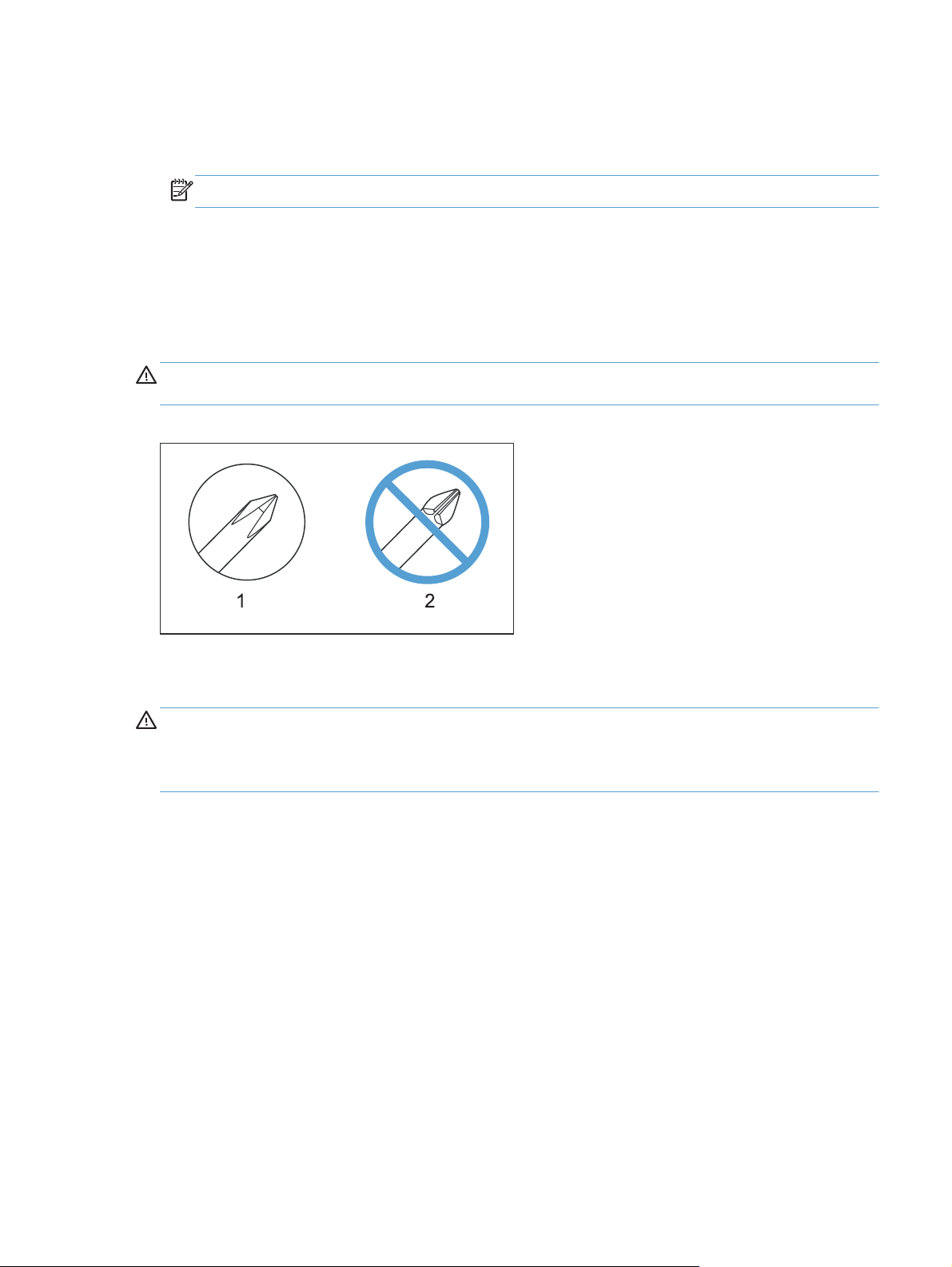
Required tools
#2 Phillips screwdriver with a magnetic tip and a 152-mm (6-in) shaft length
●
NOTE: For the best fit, use a JIS #2 Phillips screwdriver for the stapler/stacker.
Small, flat-blade screwdriver
●
Needle-nose pliers
●
ESD strap (if one is available)
●
Penlight
●
CAUTION: Always use a Phillips screwdriver (callout 1). Do not use a Pozidriv screwdriver
(callout 2) or any motorized screwdriver. These can damage screws or screw threads.
Figure 1-1 Screwdrivers
Types of screws
WARNING! Make sure that components are replaced with the correct screw type. Using the
incorrect screw (for example, substituting a long screw for the correct shorter screw) can cause damage
to the product or interfere with product operation. Do not intermix screws that are removed from one
component with the screws that are removed from another component.
For a complete list of screw types and part numbers, see the Parts chapter.
Service approach
The HP LaserJet Enterprise MFP M725 uses a field repair strategy. Defective parts are diagnosed
and replaced at the Field Replaceable Unit (FRU) assembly level. Repair normally begins by using the
product internal diagnostics and the following two-step process:
1. Isolate the problem to the major system (for example, the network or server, or the product).
2. Troubleshoot the problem by using the procedures in the troubleshooting chapter.
After you locate a faulty part, the product can usually be repaired at the assembly level by replacing
FRUs. Some mechanical assemblies might need to be repaired at the subassembly level. HewlettPackard Company does not support replacement of components on the printed circuit assembles.
ENWW
Removal and replacement strategy
3
Page 28

Before performing service
WARNING! Turn the product off, wait 5 seconds, and then remove the power cord before
attempting to service the product.
product can result.
However, the power supply should be disconnected during parts removal.
1. Remove all paper.
2. Place the product on an ESD mat (if available). If an ESD workstation or mat is not available,
ground yourself by touching the sheet-metal chassis
3. Remove the toner cartridge.
4. Remove the trays.
The power must be on for certain functional checks during troubleshooting.
After performing service
1. Reinstall the toner cartridge.
2. Reinstall the trays.
3. Return all paper to the trays.
4. Plug in the power cable and turn on the product.
If this warning is not followed, severe injury and damage to the
before
touching an ESD-sensitive part.
Parts removal order
If multiple components must be removed to gain access to an assembly, the first step of the removal
procedure lists all of the components that must be removed to gain access to that assembly. Use these
lists to determine which parts must be removed before removing other parts.
4 Chapter 1 Removal and replacement ENWW
Page 29
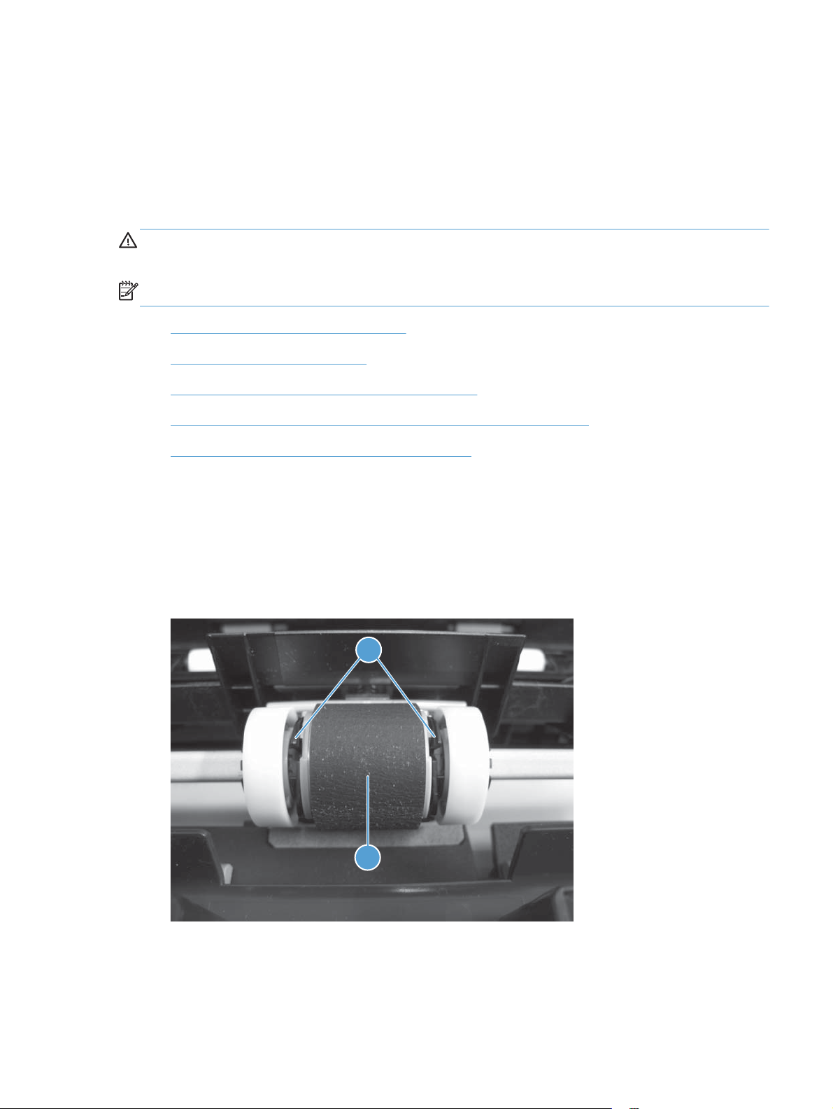
Pickup rollers
Instructions about other user-replaceable parts are provided in this section.
The product tracks the amount of use on the customer-replaceable supplies by keeping a page count.
The product prompts the user to replace certain items when a supply is depleted or a specific number of
pages have been printed.
CAUTION: Do not touch the roller surface unless you are replacing the roller. Skin oils on the roller
can cause paper pickup problems.
NOTE: Replace all of the rollers at the same time.
Tray 1 (multipurpose tray) pickup roller
●
Tray 2 and Tray 3 pickup rollers
●
Tray 4, Tray 5, and Tray 6 pickup and feed rollers
●
High capacity input feeder (HCI) pickup, feed, and separation rollers
●
Document feeder pickup and feed roller assembly
●
Tray 1 (multipurpose tray) pickup roller
1. Open the toner cartridge door.
2. Release tabs (callout 1), rotate the top of the roller away from the product, and then remove the
pickup roller (callout 2).
Figure 1-2 Remove the Tray 1 (multipurpose tray) pickup roller
1
2
ENWW
Pickup rollers
5
Page 30
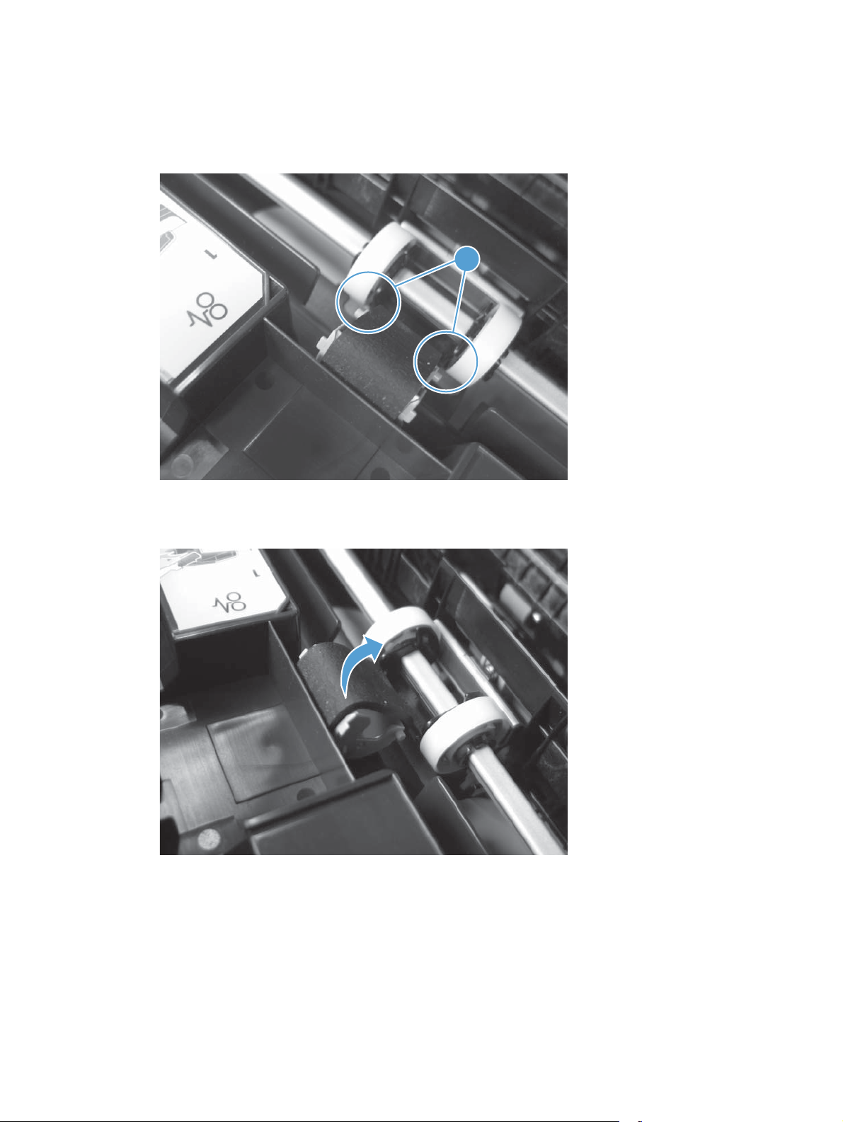
Reinstall the Tray 1 (multipurpose tray) pickup roller
1. Align the pins (callout 1) on the roller body with the slots in the holder.
Figure 1-3 Reinstall the Tray 1 (multipurpose tray) pickup roller (1 of 2)
1
2. Rotate the roller into the holder. Make sure that the tabs on the roller body snap into the holder.
Figure 1-4 Reinstall the Tray 1 (multipurpose tray) pickup roller (2 of 2)
6 Chapter 1 Removal and replacement ENWW
Page 31

Tray 2 and Tray 3 pickup rollers
CAUTION: Do not touch the roller surface unless you are replacing the roller. Skin oils on the roller
can cause paper pickup problems.
NOTE: The same removal procedures apply to the Tray 2 pickup roller and Tray 3 pickup roller.
TIP: When removing the roller assembly, take note of the position and orientation of the roller shaft
so that the assembly can be correctly reinstalled.
1. Remove the trays.
2. From the front of the product, on the right side of the tray cavity, rotate the stopper (callout 1)
down.
Figure 1-5 Remove the Tray 2 and Tray 3 pickup rollers (1 of 2)
1
ENWW
Pickup rollers
7
Page 32

3. Push the pickup roller (callout 1) in the direction indicated to remove it.
Figure 1-6 Remove the Tray 2 and Tray 3 pickup rollers (2 of 2)
1
8 Chapter 1 Removal and replacement ENWW
Page 33

Tray 4, Tray 5, and Tray 6 pickup and feed rollers
CAUTION: Do not touch the roller surface unless you are replacing the roller. Skin oils on the roller
can cause paper pickup problems.
NOTE: The same removal procedures apply to the 1x500-sheet tray, the 1x500-sheet tray stand, and
the 3x500-sheet tray stand.
1. Remove the tray from the product, and then locate the rollers on the right-hand side of the tray
cavity.
Figure 1-7 Remove the 1x500 or 3x500 rollers (1 of 2)
ENWW
Pickup rollers
9
Page 34

2. Release three tabs, and then pull the rollers in the direction indicated.
Reinstallation tip When you reinstall the rollers, make sure that the rollers snap into place.
Figure 1-8 Remove the 1x500 or 3x500 rollers (2 of 2)
10 Chapter 1 Removal and replacement ENWW
Page 35

High capacity input feeder (HCI) pickup, feed, and separation rollers
CAUTION: Do not touch the roller surface unless you are replacing the roller. Skin oils on the roller
can cause paper pickup problems.
1. Open the high capacity right tray. Lower the tray release lever (callout 1) and then remove the
right tray (callout 2).
Figure 1-9 Remove the high capacity input feeder pickup, feed, and separation rollers (1 of 4)
1
2
2. Open the high capacity left tray. Lower the tray release lever (callout 1) and then remove the left
tray (callout 2).
Figure 1-10 Remove the high capacity input feeder pickup, feed, and separation rollers (2 of 4)
1
2
ENWW
Pickup rollers
11
Page 36

3. Look up into the tray cavity and locate the rollers.
Figure 1-11 Remove the high capacity input feeder pickup, feed, and separation rollers (3 of 4)
4. Release three tabs, and then pull the rollers in the direction of the arrow. Repeat this step for
remaining rollers.
Figure 1-12 Remove the high capacity input feeder pickup, feed, and separation rollers (4 of 4)
12 Chapter 1 Removal and replacement ENWW
Page 37

Document feeder pickup and feed roller assembly
CAUTION: Do not touch the roller surface unless you are replacing the roller. Skin oils on the roller
can cause paper pickup problems.
NOTE: Always replace the document feeder separation pad and pickup and feed roller assembly at
the same time.
1. Open the document feeder cover and locate the document feeder pickup and feed roller
assembly.
Figure 1-13 Remove the document feeder pickup and feed roller assembly (1 of 3)
2. Release one tab (callout 1) to open the assembly cover.
Figure 1-14 Remove the document feeder pickup and feed roller assembly (2 of 3)
1
ENWW
Pickup rollers
13
Page 38

3. Push the roller assembly toward the front of the product, and then pull the assembly away from the
document feeder.
Figure 1-15 Remove the document feeder pickup and feed roller assembly (3 of 3)
14 Chapter 1 Removal and replacement ENWW
Page 39

Separation pads and rollers
Tray 1 separation pad assembly
CAUTION: Do not touch the pad surface unless you are replacing the assembly. Skin oils on the pad
can cause paper pickup problems.
1. Open Tray 1.
2. Release two hinge pins (callout 1) on the Tray 1 cover assembly.
Figure 1-16 Remove the Tray 1 separation pad assembly (1 of 2)
1
3. Remove one screw (callout 1), and then remove the separation pad assembly (callout 2).
Figure 1-17 Remove the Tray 1 separation pad assembly (2 of 2)
2
1
ENWW
Separation pads and rollers
15
Page 40

Tray 2 and Tray 3 separation rollers
CAUTION: Do not touch the roller surface unless you are replacing the roller. Skin oils on the roller
can cause paper pickup problems.
NOTE: The same removal procedures apply to the Tray 2 separation roller and Tray 3 separation
roller.
1. Remove the tray.
2. On the right side of the tray, remove two screws (callout 1), and then remove the roller assembly
(callout 2).
Figure 1-18 Remove the Tray 2 and Tray 3 separation rollers
1
2
16 Chapter 1 Removal and replacement ENWW
Page 41

Tray 4, 5, and 6 separation rollers
CAUTION: Do not touch the roller surface unless you are replacing the roller. Skin oils on the roller
can cause paper pickup problems.
TIP: You do not have to separate the product from the feeder to remove these rollers.
1. Remove the tray from the product, and then locate the rollers on the right-hand side of the tray
cavity.
Figure 1-19 Remove the 1x500 or 3x500 rollers (1 of 2)
2. Release three tabs, and then pull the rollers in the direction indicated.
Reinstallation tip When you reinstall the rollers, make sure that the rollers snap into place.
Figure 1-20 Remove the 1x500 or 3x500 rollers (2 of 2)
ENWW
Separation pads and rollers
17
Page 42

Document feeder separation pad
CAUTION: Do not touch the pad surface unless you are replacing the assembly. Skin oils on the pad
can cause paper pickup problems.
NOTE: Replace the separation pad and rollers at the same time.
1. Open the document feeder cover and locate the document feeder separation pad.
Figure 1-21 Remove the document feeder separation pad (1 of 3)
2. Press the tab (callout 1) toward the separation pad.
Figure 1-22 Remove the document feeder separation pad (2 of 3)
1
18 Chapter 1 Removal and replacement ENWW
Page 43

3. Rotate the separation pad assembly up and away from the document feeder, and then remove the
assembly.
CAUTION: The spring underneath the separation pad is not captive. Do not lose the spring.
Figure 1-23 Remove the document feeder separation pad (3 of 3)
Reinstall the document feeder separation pad
When the replacement separation pad assembly is installed, verify the following.
1. When the replacement separation pad assembly is installed, make sure that the spring is seated
on the spring pedestal (callout 1) under the separation pad.
Figure 1-24 Reinstall the document feeder separation pad (1 of 2)
1
ENWW
Separation pads and rollers
19
Page 44

2. Position the two tabs (callout 1) on the assembly in the holes provided in the document feeder
chassis.
Figure 1-25 Reinstall the document feeder separation pad (2 of 2)
1
20 Chapter 1 Removal and replacement ENWW
Page 45

Covers and doors
Front cover
1. Remove Tray 2 and Tray 3, and open the toner cartridge door.
2. Remove three screws (callout 1).
Figure 1-26 Remove the front cover (1 of 2)
1
3. Pull the right side of the cover (callout 1) away from the product, and then release the tab
(callout 2) on the left side of the cover to remove the cover.
Figure 1-27 Remove the front cover (2 of 2)
1
2
ENWW
Covers and doors
21
Page 46

Right rear cover
1. Open the toner cartridge door.
2. Remove one screw (callout 1), and then lift the right rear cover (callout 2) away from the product.
Figure 1-28 Remove the right rear cover
2
1
22 Chapter 1 Removal and replacement ENWW
Page 47

Left door
1. Remove the duplex unit or the duplex cover. See Duplexer or duplex cover on page 46.
2. Open the left door, and then lift up on the retainer arm (callout 1) to release it from the door
assembly (callout 2).
Figure 1-29 Remove the left door (1 of 2)
1
2
3. Pull the left side of the assembly (callout 1) away from the product, release the pin on the right
side of the assembly, and then remove the door assembly.
Figure 1-30 Remove the left door (2 of 2)
1
ENWW
Covers and doors
23
Page 48

Rear cover
1. On the rear side of the product, insert a small screwdriver (or a paper clip) into the tab slot
(callout 1) to release a hidden tab, and then slide the rear pocket cover (callout 2) in the direction
indicated to remove the cover.
Figure 1-31 Remove the rear cover (1 of 2)
2
1
2. Remove two screws (callout 1), and then slide the rear cover in the direction indicated to remove
the cover from the product.
Reinstallation tip During reinstallation, make sure that all cables are correctly positioned and
not pinched against metal parts of the chassis when you slide the rear cover into place.
Figure 1-32 Remove the rear cover (2 of 2)
1
24 Chapter 1 Removal and replacement ENWW
Page 49

Front left lower cover
1. Remove the following components or assemblies:
Tray 2 and Tray 3.
●
Front cover. See
●
2. At the front of the product, remove one screw (callout 1), and then remove the cover (callout 2)
from the product.
Figure 1-33 Remove the front left lower cover
Front cover on page 21.
1
2
ENWW
Covers and doors
25
Page 50

Front right lower cover
1. Remove the following components or assemblies:
Tray 2 and Tray 3.
●
Front cover. See
●
NOTE: If optional trays are installed, release the tray lock below the front right lower cover. Pull
Tray 4 out, and then rotate the blue lock lever to the right.
2. Remove one screw (callout 1), release one tab (callout 2), and then remove the cover (callout 3)
from the product.
Figure 1-34 Remove the front right lower cover
Front cover on page 21.
1
3
2
26 Chapter 1 Removal and replacement ENWW
Page 51

Face-down cover
1. Open the toner cartridge door.
2. At the front of the product, remove one screw (callout 1), release one tab (callout 2) at the back of
the metal rail under the cover, and then lift the left side of the cover to release three tabs on the
rear side (callout 3) of the cover to remove the cover from the product.
NOTE: It might be easier to remove this cover if the stapler/stacker output bin is removed first.
See
Stapler/stacker output bin assembly on page 197.
Reinstallation tip When you reinstall the face-down cover, make sure that the three tabs
(callout 3) are properly inserted in the paper delivery assembly.
Figure 1-35 Remove the face-down cover
1
3
2
ENWW
Covers and doors
27
Page 52

Tray 1 (multipurpose tray) cover
1. Remove the right rear cover. See Right rear cover on page 22.
2. Open Tray 1.
3. Inside Tray 1 release two pins (callout 1).
Figure 1-36 Remove the Tray 1 (multipurpose tray) cover (1 of 2)
1
4. Raise the cover to a half-closed position, pull the right side hinge slot (callout 1) away from the
hinge pin (callout 2), and then remove the cover (callout 3) from the product.
Figure 1-37 Remove the Tray 1 (multipurpose tray) cover (2 of 2)
2
3
1
28 Chapter 1 Removal and replacement ENWW
Page 53

Right door
1. Remove the right rear cover. See Right rear cover on page 22.
2. On the right side of the product, remove two screws (callout 1).
Figure 1-38 Remove the right door (1 of 2)
1
3. Open the right door (callout 1), move it slightly toward the front of the product, and then release
the door retainer arm (callout 2) to remove the right door.
Figure 1-39 Remove the right door (2 of 2)
2
1
ENWW
Covers and doors
29
Page 54

Reinstall the right door
Make sure that you correctly position the spring (callout 1) inside the metal chassis (callout 2) when you
reinstall the right door.
Figure 1-40 Reinstall the right door
2
1
30 Chapter 1 Removal and replacement ENWW
Page 55

Left handle cover
1. Remove the rear cover. See Rear cover on page 24.
2. Release one tab (callout 1), and then slide the cover (callout 2) in the direction indicated to
remove it from the product.
Figure 1-41 Remove the left handle cover
1 2
ENWW
Covers and doors
31
Page 56

Left inner lower cover
1. Remove the left door. See Left door on page 23.
2. Remove one screw (callout 1), release one tab (callout 2), and then slide the left inner lower cover
(callout 3) in the direction indicated to remove it from the product.
Figure 1-42 Remove the left inner lower cover
1
2
3
32 Chapter 1 Removal and replacement ENWW
Page 57

Left inner rear cover
1. Remove the following components or assemblies:
Left door. See
●
Rear cover. See
●
Left inner lower cover. See
●
Fuser. See
●
2. Release two tabs (callout 1).
Figure 1-43 Remove the left inner rear cover (1 of 2)
Left door on page 23.
Rear cover on page 24.
Left inner lower cover on page 32.
Fuser on page 48.
1
ENWW
Covers and doors
33
Page 58

3. Slide the left inner rear cover (callout 1) in the direction indicated to remove the cover from the
product.
Figure 1-44 Remove the left inner rear cover (2 of 2)
1
34 Chapter 1 Removal and replacement ENWW
Page 59

Left inner front cover
1. Remove the following components or assemblies:
Front cover. See
●
Left door. See
●
Front left lower cover. See
●
Left inner lower cover. See
●
Fuser. See
●
2. On the left side of the product, release one tab (callout 1).
Figure 1-45 Remove the left inner front cover (1 of 2)
Front cover on page 21.
Left door on page 23.
Front left lower cover on page 25.
Left inner lower cover on page 32.
Fuser on page 48.
1
ENWW
Covers and doors
35
Page 60

3. Inside the product, slide the cover (callout 1) out to remove it from the product.
Figure 1-46 Remove the left inner front cover (2 of 2)
1
36 Chapter 1 Removal and replacement ENWW
Page 61

Right handle cover
1. Remove the following components or assemblies:
Front cover. See
●
Right rear cover. See
●
Front right lower cover. See
●
Tray 1 cover. See
●
Right door. See
●
2. On the right side of the product, remove one screw (callout 1), release two tabs (callout 2), and
then pull the top of the cover (callout 3) to remove it from the product.
Reinstallation tip You might have to move the cover up and down during reinstallation to
make sure that it is correctly aligned and snaps into place.
Figure 1-47 Remove the right handle cover
Front cover on page 21.
Right rear cover on page 22.
Front right lower cover on page 26.
Tray 1 (multipurpose tray) cover on page 28.
Right door on page 29.
3
1
2
ENWW
Covers and doors
37
Page 62

Face-down side cover
1. Remove the following components or assemblies:
Front cover. See
●
Face-down cover. See
●
Front upper cover. See .
●
2. On the left side at the front of the product, release one tab (callout 1), and then remove the cover
(callout 2) from the product.
Figure 1-48 Remove the face-down side cover
Front cover on page 21.
Face-down cover on page 27.
Front upper cover on page 39.
2
1
38 Chapter 1 Removal and replacement ENWW
Page 63

Front upper cover
1. Remove the front cover. See Front cover on page 21.
2. On the front side of the product, release two tabs (callout 1), and then remove the cover (callout 2)
from the product.
Figure 1-49 Remove the front upper cover
2
1
ENWW
Covers and doors
39
Page 64

Top rear outer cover
1. Remove the rear cover. See Rear cover on page 24.
2. On the rear side of the product, remove one screw (callout 1), and then remove the cover
(callout 2) from the product.
Figure 1-50 Remove the top rear outer cover
2
1
40 Chapter 1 Removal and replacement ENWW
Page 65

Output upper cover
1. If the product includes a stapler/stacker, remove the stapler/stacker. See Stapler/stacker assembly
on page 211.
2. Open the left door.
3. From the right side of the product, release two tabs (callout 1), and then remove the cover
(callout 2) from the product.
Figure 1-51 Remove the output upper cover (1 of 2)
2
1
The figure below shows the location of the tabs (callout 1).
Figure 1-52 Remove the output upper cover (2 of 2)
1
ENWW
Covers and doors
41
Page 66

Top rear inner cover
1. Remove the following components or assemblies:
Right rear cover. See
●
Rear pocket cover. See step 1 of
●
Face-down cover. See
●
Output upper cover. See
●
Stapler/stacker (if it is installed). See
●
2. On the rear side of the product, release one tab (callout 1), and then slide the cover (callout 2) in
the direction indicated to remove it from the product.
Figure 1-53 Remove the top rear inner cover
Right rear cover on page 22.
Rear cover on page 24.
Face-down cover on page 27.
Output upper cover on page 41.
Stapler/stacker assembly on page 211.
2
1
42 Chapter 1 Removal and replacement ENWW
Page 67

Left inner front upper cover
1. Remove the following components or assemblies:
Front cover. See
●
Front upper cover. See
●
Output upper cover. See
●
Stapler-stacker (if it is installed). See
●
2. On the front side of the product, release one tab (callout 1), and then slide the cover (callout 2) in
the direction indicated to remove it from the product.
Figure 1-54 Remove the left inner front upper cover
Front cover on page 21.
Front upper cover on page 39.
Output upper cover on page 41.
Stapler/stacker assembly on page 211.
2
1
ENWW
Covers and doors
43
Page 68

Left inner rear upper cover
1. Remove the following components or assemblies:
Rear cover. See
●
Top rear outer cover. See
●
Stapler-stacker (if it is installed). See
●
2. On the rear side of the product, release one tab (callout 1), and then slide the cover (callout 2) in
the direction indicated to remove it from the product.
Figure 1-55 Remove the left inner rear upper cover
Rear cover on page 24.
Top rear outer cover on page 40.
Stapler/stacker assembly on page 211.
1 2
44 Chapter 1 Removal and replacement ENWW
Page 69

Main assemblies
Duplexer or duplex cover
●
Fuser
●
Control panel assembly
●
Paper delivery assembly
●
Registration assembly
●
Transfer roller
●
Paper feed assembly
●
Laser scanner
●
Toner cartridge door
●
Formatter cage assembly
●
Upper cassette pickup assembly
●
Lower cassette pickup assembly
●
Lifter drive assembly
●
Main drive assembly
●
Fuser drive assembly
●
ENWW
Main assemblies
45
Page 70

Duplexer or duplex cover
Remove the duplexer
NOTE: If the product is equipped with a duplexer, complete the following steps.
1. At the left side of the product, pull out the duplexer until it stops.
Figure 1-56 Remove the duplexer (1 of 2)
2. Lift up the duplexer and slightly pull it toward you to remove it.
Figure 1-57 Remove the duplexer (2 of 2)
46 Chapter 1 Removal and replacement ENWW
Page 71

Remove the duplexer cover
NOTE: If the product does not have a duplexer, complete the following steps.
1. On the left side of the product, place a finger in the notch (callout 1) at the bottom of the cover.
Figure 1-58 Remove the duplex cover
1
2. Pull the cover (callout 1) in the direction indicated to remove it from the product.
Figure 1-59 Remove the duplex cover
1
ENWW
Main assemblies
47
Page 72

Fuser
1. Remove the following components or assemblies:
Left door. See
●
Duplexer or duplexer access cover. See
●
2. Turn the two latches (callout 1) in the direction indicated, and then pull the fuser (callout 2) straight
out to remove it from the product.
NOTE: On the right side latch, you must reach behind the fuser door retainer to gain access to
the latch.
Figure 1-60 Remove the fuser
Left door on page 23.
Duplexer or duplex cover on page 46.
2
1
48 Chapter 1 Removal and replacement ENWW
Page 73

Control panel assembly
1. On the front side of the product, tilt the control panel up away from the product, remove two
thumb-screws (callout 1), and then slide the control panel away from the product.
Figure 1-61 Remove the control panel (1 of 2)
1
2. On the underside of the control panel, disconnect two connectors (callout 1) to remove the control
panel from the product.
Figure 1-62 Remove the control panel (2 of 2)
1
ENWW
Main assemblies
49
Page 74

Paper delivery assembly
1. Remove the following components or assemblies:
Face-down cover. See
●
Fuser. See
●
2. At the top of the product near the left side, disconnect one connector (callout 1).
Figure 1-63 Remove the paper delivery assembly (1 of 2)
Fuser on page 48.
Face-down cover on page 27.
1
50 Chapter 1 Removal and replacement ENWW
Page 75

3. Remove four screws (callout 1), and then pull the paper delivery assembly (callout 2) straight out to
remove it from the product.
CAUTION: When holding the paper delivery assembly, do not touch the static eliminators.
Figure 1-64 Remove the paper delivery assembly (2 of 2)
1
2
ENWW
Main assemblies
51
Page 76

Install a replacement paper delivery assembly
If you are replacing the paper delivery assembly, remove the output upper cover, link, and lever, and
then install them on the replacement assembly.
1. Release two tabs (callout 1), and then remove the output upper cover (callout 2).
Figure 1-65 Install a replacement paper delivery assembly (1 of 3)
1
2
2. Release one tab (callout 1).
Figure 1-66 Install a replacement paper delivery assembly (2 of 3)
1
52 Chapter 1 Removal and replacement ENWW
Page 77

3. Remove the link (callout 1) and the lever (callout 2).
Figure 1-67 Install a replacement paper delivery assembly (3 of 3)
2
1
ENWW
Main assemblies
53
Page 78

Registration assembly
1. Open the toner cartridge door.
2. Before proceeding, use the following two figures to locate the left and right registration mounting
screws.
Figure 1-68 Registration assembly left screw
Figure 1-69 Registration assembly right screw
54 Chapter 1 Removal and replacement ENWW
Page 79

3. From the right side of the product, remove two screws (callout 1).
Figure 1-70 Remove the registration assembly (1 of 2)
1
4. Carefully pull the registration assembly (callout 1) out of the product.
Figure 1-71 Remove the registration assembly (2 of 2)
ENWW
1
Reinstallation tip When reassembling the registration assembly, make sure that the hooks (callout1)
on the rear side of assembly are seated in the slits (callout 2) on both sides. See the following figure.
Main assemblies
55
Page 80

Figure 1-72 Reinstalling the registration assembly
121
1
2
56 Chapter 1 Removal and replacement ENWW
Page 81

Transfer roller
1. Open the toner cartridge door.
2. On the right end of the roller, pull up on the tab (callout 1) to loosen the roller (callout 2), and then
remove the roller from the product.
Figure 1-73 Remove the transfer roller
1
2
ENWW
Main assemblies
57
Page 82

Paper feed assembly
1. Remove the following components or assemblies:
Fuser. See
●
Registration assembly. See
●
Transfer roller. See
●
2. On the right side of the product, release one tab (callout 1).
Figure 1-74 Remove the paper feed assembly (1 of 4)
Fuser on page 48.
Registration assembly on page 54.
Transfer roller on page 57.
1
3. Hold up the right side of the paper feed assembly (callout 1).
Figure 1-75 Remove the paper feed assembly (2 of 4)
1
58 Chapter 1 Removal and replacement ENWW
Page 83

4. Beneath the paper feed assembly (callout 1), remove the connector cover (callout 2) by pulling the
rear part of the cover up and toward you to release the front part of the cover.
Figure 1-76 Remove the paper feed assembly (3 of 4)
2
1
Reinstallation tip When reinstalling the connector cover, insert the front side (callout 1) first,
and then press down on the rear end (callout 2) of the cover to snap it in place.
Figure 1-77 Reinstall the connector cover
2
1
ENWW
Main assemblies
59
Page 84

5. Slide the paper feed assembly (callout 1) in the direction indicated to remove it from the product.
Figure 1-78 Remove the paper feed assembly (4 of 4)
1
Reinstallation tip When reinstalling the paper feed assembly, turn the shutter (callout 1) frontward
so that the high-voltage power supply assembly (callout 2) is not damaged.
Figure 1-79 Reinstall the paper feed assembly (1 of 2)
1
2
Reinstallation tip When reinstalling the paper feed assembly, make sure that the pins (callout 1)
on the rear side of the paper feed assembly are seated in the grooves on the high-voltage power supply
assembly. The following figure shows the view from the left side of the product.
60 Chapter 1 Removal and replacement ENWW
Page 85

Figure 1-80 Reinstall the paper feed assembly (2 of 2)
1
ENWW
Main assemblies
61
Page 86

Laser scanner
1. Remove the face-down cover. See Face-down cover on page 27.
2. Remove the foam anti-static pad (callout 1) from the laser scanner.
Figure 1-81 Remove the laser scanner (1 of 3)
1
3. Disconnect one flat flexible cable (callout 1) and two connectors (callout 2), and then release the
cables from the cable guides (callout 3).
Figure 1-82 Remove the laser scanner (2 of 3)
3
1
2
62 Chapter 1 Removal and replacement ENWW
Page 87

4. Remove four screws (callout 1), and then remove the laser scanner (callout 2) from the product.
NOTE: If the stapler-stacker is installed, you will need a 38 mm (1.5 in) short-shaft screwdriver
with a magnetic-tip to remove the screws. Or you can remove the stapler/stacker output bin. See
Stapler/stacker output bin assembly on page 197.
Figure 1-83 Remove the laser scanner (3 of 3)
2
1
ENWW
Main assemblies
63
Page 88

Toner cartridge door
1. Remove the following components or assemblies:
Front cover. See
●
Right rear cover. See
●
Tray 1 (multipurpose tray) cover. See
●
Right door. See
●
2. Open the toner cartridge door.
3. Inside the door, use needle-nose pliers to release one tab (callout 1), and then release the link arm
(callout 2).
Figure 1-84 Remove the toner cartridge door (1 of 6)
Front cover on page 21.
Right rear cover on page 22.
Tray 1 (multipurpose tray) cover on page 28.
Right door on page 29.
2
1
64 Chapter 1 Removal and replacement ENWW
Page 89

4. Release one tab (callout 1), and then remove the pin (callout 2) from the door linkage.
CAUTION: Be careful not to break the tab off of the pin.
Figure 1-85 Remove the toner cartridge door (2 of 6)
2
1
5. To the right of the door, disconnect two connectors (callout 1), and then release the cables
(callout 2) from the cable guide.
Figure 1-86 Remove the toner cartridge door (3 of 6)
1
2
ENWW
Main assemblies
65
Page 90

6. While partially closing the cartridge door (callout 1), pull the link arm (callout 2) in the direction
indicated and release it from the notch in the cartridge door.
Figure 1-87 Remove the toner cartridge door (4 of 6)
1
2
7. Remove four screws (callout 1).
Figure 1-88 Remove the toner cartridge door (5 of 6)
1
66 Chapter 1 Removal and replacement ENWW
Page 91

8. Slide the cartridge door assembly (callout 1) in the direction indicated to remove it from the
product.
Figure 1-89 Remove the toner cartridge door (6 of 6)
1
Reinstallation tip When reinstalling the cartridge door, insert the pin (callout 1) pointing as shown
in the following figure while the cartridge door is open.
Figure 1-90 Reinstall the cartridge door assembly (1 of 2)
1
Reinstallation tip When reinstalling the cartridge door, wind the cable (callout 1) around the cable
guide counter-clockwise and run through the groove (callout 2) before connecting it as shown in the
following figure.
ENWW
Main assemblies
67
Page 92

Figure 1-91 Reinstall the cartridge door assembly (2 of 2)
2
1
68 Chapter 1 Removal and replacement ENWW
Page 93

Formatter cage assembly
1. Remove the following components or assemblies:
Rear cover. See
●
Formatter. See
●
2. On the rear side of the product, disconnect two connectors (callout 1), one flat flexible cable
(callout 2), and then five connectors at the top of the assembly (callout 3).
Figure 1-92 Remove the formatter cage (1 of 2)
Rear cover on page 24.
Formatter PCA on page 114.
3
1
2
3. Remove three screws (callout 1), and then lift up the bottom of the formatter cage (callout 2) to
remove it from the product.
Figure 1-93 Remove the formatter cage (2 of 2)
1
2
ENWW
Main assemblies
69
Page 94

Upper cassette pickup assembly
1. Remove the following components or assemblies:
Front cover. See
●
Right rear cover. See
●
Rear cover. See
●
Tray 1 (multipurpose tray) cover. See
●
Right door. See
●
Toner cartridge door. See
●
Formatter cage. See
●
2. Remove three screws (callout 1), and then remove the gear assembly (callout 2).
Figure 1-94 Remove the upper cassette pickup assembly (1 of 4)
Front cover on page 21.
Right rear cover on page 22.
Rear cover on page 24.
Tray 1 (multipurpose tray) cover on page 28.
Right door on page 29.
Toner cartridge door on page 64.
Formatter cage assembly on page 69.
1
2
70 Chapter 1 Removal and replacement ENWW
Page 95

3. Disconnect two connectors (callout 1), release the cables (callout 2) from the cable guide, remove
the C-clip (callout 3) from the clutch shaft, and then pull the upper cassette pickup clutch (callout 4)
to remove it from the product.
Figure 1-95 Remove the upper cassette pickup assembly (2 of 4)
1
3
4
2
4. Release one tab (callout 1), and then remove the gear cover (callout 2).
Figure 1-96 Remove the upper cassette pickup assembly (3 of 4)
1
2
ENWW
Main assemblies
71
Page 96

5. Remove four screws (callout 1), and then pull the upper cassette pickup assembly (callout 2) to
remove it from the product.
Figure 1-97 Remove the upper cassette pickup assembly (4 of 4)
1
2
72 Chapter 1 Removal and replacement ENWW
Page 97

Lower cassette pickup assembly
1. Remove the following components or assemblies:
Right rear cover. See
●
Rear cover. See
●
Tray 1 (multipurpose tray) cover. See
●
Right door. See
●
Formatter cage. See
●
2. Remove three screws (callout 1), and then remove the gear assembly (callout 2).
Figure 1-98 Remove the lower cassette pickup assembly (1 of 3)
Right rear cover on page 22.
Rear cover on page 24.
Tray 1 (multipurpose tray) cover on page 28.
Right door on page 29.
Formatter cage assembly on page 69.
1
2
ENWW
Main assemblies
73
Page 98

3. Disconnect two connectors (callout 1) (J43), release the cables (callout 2) from the cable guide,
remove the C-clip (callout 3) from the clutch shaft, and then pull the lower cassette pickup clutch
(callout 4) to remove it from the product.
Figure 1-99 Remove the lower cassette pickup assembly (2 of 3)
1
2
3
4
4. Remove four screws (callout 1), and then pull the lower cassette pickup assembly (callout 2) to
remove it from the product.
Figure 1-100 Remove the lower cassette pickup assembly (3 of 3)
1
2
74 Chapter 1 Removal and replacement ENWW
Page 99

Lifter drive assembly
1. Remove the following components or assemblies:
Rear cover. See
●
Formatter cage. See
●
Low-voltage power supply. See
●
2. Disconnect three connectors (callout 1), and then release the cables (callout 2) from the cable
guide.
Figure 1-101 Remove the lifter driver assembly (1 of 2)
Rear cover on page 24.
Formatter cage assembly on page 69.
Low-voltage power supply assembly on page 119.
1
2
ENWW
Main assemblies
75
Page 100

3. Remove four screws (callout 1), and then remove the lifter drive assembly (callout 2) from the
product.
Figure 1-102 Remove the lifter driver assembly (2 of 2)
1
2
76 Chapter 1 Removal and replacement ENWW
 Loading...