

Page 1
HP LaserJet M9059 MFP
Service Manual
Page 2

Page 3

HP LaserJet M9059 MFP
Service Manual
Page 4

Copyright and License
© 2009 Copyright Hewlett-Packard
Development Company, L.P.
Trademark Credits
®
Adobe
, Acrobat®, and PostScript® are
trademarks of Adobe Systems Incorporated.
Reproduction, adaptation, or translation
without prior written permission is prohibited,
except as allowed under the copyright laws.
The information contained herein is subject
to change without notice.
The only warranties for HP products and
services are set forth in the express warranty
statements accompanying such products
and services. Nothing herein should be
construed as constituting an additional
warranty. HP shall not be liable for technical
or editorial errors or omissions contained
herein.
Part number: CE800–90928
Edition 1, 06/2009
Java™ is a US trademark of Sun
Microsystems, Inc.
Microsoft®, Windows®, and Windows®XP
are U.S. registered trademarks of Microsoft
Corporation.
Windows Vista® is either a registered
trademark or trademark of Microsoft
Corporation in the United States and/or other
countries.
ENERGY STAR
®
logo
are U.S. registered marks of the United
®
and the ENERGY STAR
States Environmental Protection Agency.
Page 5

Table of contents
1 Product basics
Product introduction ............................................................................................................................. 2
Product features ................................................................................................................................... 3
Product walkaround .............................................................................................................................. 7
Output devices ..................................................................................................................................... 8
3,000-sheet stacker ............................................................................................................. 8
3,000-sheet stapler/stacker ................................................................................................. 8
Paper handling features ...................................................................................... 8
Stapling information ............................................................................................ 8
Multifunction finisher ............................................................................................................ 8
Paper handling features ...................................................................................... 8
Stapling information ............................................................................................ 9
Booklets .............................................................................................................. 9
8-bin mailbox ..................................................................................................................... 10
2 Control panel
Use the control panel ......................................................................................................................... 12
Use the Administration menu ............................................................................................................. 15
Control-panel layout ........................................................................................................... 12
Home screen ..................................................................................................................... 13
Buttons on the touchscreen ............................................................................................... 14
Control-panel help system ................................................................................................. 14
Navigate the Administration menu ..................................................................................... 15
Information menu ............................................................................................................... 16
Default Job Options menu ................................................................................................. 17
Default Options for Originals ............................................................................. 17
Default Copy Options ........................................................................................ 18
Default Fax Options .......................................................................................... 19
Default E-mail Options ...................................................................................... 20
Default Send to Folder Options ......................................................................... 21
Default Print Options ......................................................................................... 22
Time/Scheduling menu ...................................................................................................... 23
Management menu ............................................................................................................ 25
Initial Setup menu .............................................................................................................. 26
ENWW iii
Page 6

Device Behavior menu ....................................................................................................... 39
Print Quality menu ............................................................................................................. 43
Troubleshooting menu ....................................................................................................... 45
Resets menu ...................................................................................................................... 47
Service menu ..................................................................................................................... 47
3 Paper and print media
Understand paper and print media use .............................................................................................. 50
Supported paper and print media sizes .............................................................................................. 51
Custom paper sizes ............................................................................................................................ 52
Special paper or print media guidelines ............................................................................................. 53
Load paper and print media ............................................................................................................... 54
Load Tray 1 ........................................................................................................................ 54
Load Trays 2, 3, and 4 ....................................................................................................... 55
Configure trays ................................................................................................................................... 61
Configure a tray when loading media ................................................................................ 61
Configure a tray by using the Supplies Status button on the touchscreen ........................ 61
Select the media by source, type, or size .......................................................................... 61
Select the output bin ........................................................................................................................... 63
Select an output location ................................................................................................... 64
Networking and I/O ........................................................................................... 26
Fax Setup .......................................................................................................... 35
E-mail Setup ...................................................................................................... 38
Send Setup menu ............................................................................................. 38
Source ............................................................................................................... 62
Type and Size ................................................................................................... 62
Printing .............................................................................................................. 64
Copying ............................................................................................................. 64
4 Manage and maintain
Information pages ............................................................................................................................... 66
Embedded Web server ....................................................................................................................... 68
Open the embedded Web server by using a network connection ..................................... 68
Embedded Web server sections ........................................................................................ 69
Use HP Web Jetadmin software ........................................................................................................ 72
HP Printer Utility for Macintosh .......................................................................................................... 73
Open the HP Printer Utility ................................................................................................. 73
Print a cleaning page ......................................................................................................... 73
Print a configuration page .................................................................................................. 73
View supplies status .......................................................................................................... 73
Upload a file to the product ................................................................................................ 74
Update the firmware .......................................................................................................... 74
Activate the two-sided printing (duplexing) mode .............................................................. 74
iv ENWW
Page 7

Lock or unlock storage devices ......................................................................................... 74
Save or print stored jobs .................................................................................................... 75
Configure trays .................................................................................................................. 75
Change network settings ................................................................................................... 75
Open the embedded Web server ....................................................................................... 76
Set up e-mail alerts ............................................................................................................ 76
Security features ................................................................................................................................ 77
Secure the embedded Web server .................................................................................... 77
Secure Disk Erase ............................................................................................................. 77
Data affected ..................................................................................................... 77
Gain access to Secure Disk Erase .................................................................... 78
Additional Information ....................................................................................... 78
Security lock ...................................................................................................................... 78
Authentication .................................................................................................................... 78
Lock the control-panel menus ............................................................................................ 78
Set the real-time clock ........................................................................................................................ 80
Clean the product ............................................................................................................................... 81
Print a cleaning page ......................................................................................................... 81
Clean the product hardware .............................................................................................. 81
Clean the ADF delivery system ........................................................................................ 83
Configure alerts .................................................................................................................................. 88
Manage supplies ................................................................................................................................ 89
HP print cartridges ............................................................................................................. 89
Non-HP print cartridges ..................................................................................................... 89
Print cartridge authentication ............................................................................................. 89
HP fraud hotline ................................................................................................................. 89
Print cartridge storage ....................................................................................................... 89
Print cartridge life expectancy ............................................................................................ 90
Check the print cartridge life .............................................................................................. 90
Control panel ..................................................................................................... 90
Embedded Web server ..................................................................................... 90
HP Web Jetadmin ............................................................................................. 90
Printer maintenance kit ....................................................................................................................... 91
Manage memory ................................................................................................................................ 92
Determine memory requirements ...................................................................................... 92
Install memory ................................................................................................................... 92
Verify memory installation .................................................................................................. 95
Economy settings ............................................................................................................................... 96
Sleep and wake ................................................................................................................. 96
5 Theory of operation
Basic operation ................................................................................................................................... 98
Sequence of operation ....................................................................................................... 99
ENWW v
Page 8

Product start up sequence (turn on product) ................................................................... 102
Timing chart ..................................................................................................................... 103
Scanner subsystem ......................................................................................................... 103
Mechanical structure ....................................................................................... 103
Motors and fans .............................................................................................. 105
Basic block diagram ........................................................................................ 106
Basic system configuration ............................................................................. 107
Scanner unit systems ..................................................................... 107
Scan mode ..................................................................................... 108
Power supply assembly .................................................................. 108
Sleep mode .................................................................................... 109
Low-voltage power supply circuit .................................................... 110
Protective functions ........................................................................ 111
Scanner controller circuit ................................................................ 112
Flatbed operation ............................................................................................ 114
Flatbed document exposure control ............................................... 114
Flatbed optical drive control ............................................................ 114
Flatbed optical unit operation ......................................................... 115
Flatbed document size detection .................................................... 116
ADF operation ................................................................................................. 118
ADF document exposure control .................................................... 118
ADF document feed control ............................................................ 119
ADF document size detection ......................................................... 121
ADF feeder sensors ........................................................................ 122
ADF document skew detection ....................................................... 122
Scanned data flow ........................................................................................... 123
Copy processor ............................................................................................... 124
Scanning process control signals ................................................... 125
Typical scanning process flow ........................................................ 126
Engine control system ...................................................................................................................... 127
DC controller PCA ........................................................................................................... 128
High-voltage power supply circuit .................................................................................... 129
Low-voltage power supply ............................................................................................... 131
Fuser control circuit ......................................................................................................... 131
Formatter system ............................................................................................................................. 133
Formatter hardware ......................................................................................................... 133
Laser/scanner system ...................................................................................................................... 134
Image formation system ................................................................................................................... 135
The image formation process .......................................................................................... 135
Print cartridge .................................................................................................................. 136
Print cartridge design ...................................................................................... 137
No-shake toner ................................................................................................ 137
Cartridge memory ........................................................................................... 137
Toner seal ....................................................................................................... 137
vi ENWW
Page 9

Toner level detection ....................................................................................... 138
Pickup and feed system ................................................................................................................... 139
Media-size detection ........................................................................................................ 139
Media-level detection ....................................................................................................... 139
Multifeed prevention ........................................................................................................ 139
Transparency media detection ........................................................................................ 139
Fuser-wrapping jam detection ......................................................................................... 139
Jam detection .................................................................................................................. 140
Tray 1 ............................................................................................................................................... 145
Tray 1 driver PCA ............................................................................................................ 145
Tray 1 power supply ........................................................................................................ 145
Tray 1 sequence of operation .......................................................................................... 145
Tray 1 pickup and feed .................................................................................................... 146
Tray 1 jam detection ........................................................................................................ 146
Tray 4 ............................................................................................................................................... 147
Tray 4 driver PCA ............................................................................................................ 147
Tray 4 power supply ........................................................................................................ 147
Tray 4 sequence of operation .......................................................................................... 147
Tray 4 pickup and feed .................................................................................................... 148
Tray 4 media level and media size detection ................................................................... 148
Tray 4 jam detection ........................................................................................................ 148
6 Removal and replacement
Removal and replacement strategy .................................................................................................. 150
Repair notices .................................................................................................................................. 150
Electrostatic discharge ..................................................................................................................... 151
Required tools .................................................................................................................................. 151
Product orientation ........................................................................................................................... 152
Front and right side orientation ........................................................................................ 152
Back and left side orientation ........................................................................................... 153
Scanner assembly covers ................................................................................................................ 154
Control panel ................................................................................................................... 154
ADF feeder cover handle ................................................................................................. 157
ADF back cover ............................................................................................................... 157
ADF front cover ................................................................................................................ 159
Lower delivery roller cover ............................................................................................... 159
White board cover ............................................................................................................ 160
Copy processor/connect board ........................................................................................ 161
Reinstall the control panel ............................................................................... 155
ADF feeder cover ............................................................................................ 155
Reinstall the ADF feeder cover ....................................................................... 156
Reinstall the delivery roller cover .................................................................... 160
Reinstall the copy processor/connect board ................................................... 162
ENWW vii
Page 10

Flatbed rail cover ............................................................................................................. 162
Flatbed back cover .......................................................................................................... 162
Flatbed right cover ........................................................................................................... 164
Reinstall the flatbed right cover ....................................................................... 164
Flatbed left cover ............................................................................................................. 165
Flatbed upper front cover ................................................................................................. 166
Flatbed lower front cover ................................................................................................. 166
ADF base cover assembly ............................................................................................... 167
Reinstall the ADF base cover assembly ......................................................... 171
Scanner glass .................................................................................................................. 172
Reinstall the scanner glass ............................................................................. 173
Scan engine internal assemblies ...................................................................................................... 174
ADF and flatbed internal assemblies ............................................................................... 174
ADF main assembly ........................................................................................ 174
Reinstall the ADF main assembly ................................................... 179
ADF optical assembly ..................................................................................... 179
Reinstall the ADF optical assembly ................................................ 186
ADF shading filter ............................................................................................ 186
Flatbed optical unit .......................................................................................... 188
Reinstall the flatbed optical unit ...................................................... 190
Switch and solenoids ....................................................................................................... 191
ADF feeder cover detection switch ................................................................. 191
Weight solenoid ............................................................................................... 192
Shutter solenoid .............................................................................................. 192
Motors and fans ............................................................................................................... 193
Pickup motor ................................................................................................... 193
Reinstall the pickup motor .............................................................. 194
Delivery motor ................................................................................................. 194
Reinstall .......................................................................................... 195
Flatbed motor .................................................................................................. 195
Reinstall the flatbed motor .............................................................. 197
Power supply assembly .................................................................................. 197
Reinstall power supply assembly ................................................... 200
ADF fan assembly ........................................................................................... 200
Reinstall the ADF fan assembly ..................................................... 201
Flatbed fan assembly ...................................................................................... 201
Rollers and belts .............................................................................................................. 202
Pickup roller (D roller) ..................................................................................... 202
Pickup roller assembly .................................................................................... 202
Reinstall the pickup roller assembly ............................................... 203
Feed roller assembly ....................................................................................... 203
Lower registration roller assembly .................................................................. 204
Reinstall the lower registration assembly ....................................... 210
Lower delivery roller ........................................................................................ 210
viii ENWW
Page 11

Reinstall the lower delivery roller .................................................... 211
Upper delivery roller assembly ........................................................................ 211
Reinstall the upper delivery roller assembly ................................... 212
Separation belt assembly ................................................................................ 212
Reinstall the separation belt assembly ........................................... 215
Separation belts .............................................................................................. 215
Reinstall the separation belts ......................................................... 217
PCAs ................................................................................................................................ 217
ADF intermediate PCA .................................................................................... 217
ADF width detection sensor assembly ............................................................ 218
Reinstall the ADF width detection sensor assembly ....................... 218
Flatbed intermediate PCA ............................................................................... 219
Scanner controller board ................................................................................. 220
Intermediate PCA ............................................................................................ 222
Scan engine ..................................................................................................................... 223
Reinstall the scan engine ................................................................................ 227
Laser/scanner assembly .................................................................................................. 228
Delivery fan assembly ...................................................................................................... 229
Delivery motor .................................................................................................................. 231
Print engine covers ........................................................................................................................... 232
Front cover ....................................................................................................................... 232
Right door ........................................................................................................................ 233
Right lower cover ............................................................................................................. 234
Left upper cover ............................................................................................................... 23 4
Reinstall the left upper cover ........................................................................... 235
Left door and diverter ....................................................................................................... 236
Left back cover ................................................................................................................ 236
Back cover ....................................................................................................................... 237
Right and left rail covers .................................................................................................. 238
Front assemblies .............................................................................................................................. 239
Cartridge release lever .................................................................................................... 239
Print cartridge .................................................................................................................. 240
Reinstall the print cartridge ............................................................................. 241
Transfer-roller assembly .................................................................................................. 241
Reinstall the transfer-roller assembly .............................................................. 242
Tray 2 and Tray 3 (interchangeable) ............................................................................... 242
Rollers (pickup, feed, or separation) ................................................................................ 243
Fuser-jam-removal knob .................................................................................................. 243
Reinstall the fuser-jam-removal knob .............................................................. 244
Registration-jam-removal knob ........................................................................................ 244
Reinstall the registration-jam-removal knob .................................................... 245
Right assemblies .............................................................................................................................. 246
Tray 1 ............................................................................................................................... 246
Paper-input unit (PIU) ...................................................................................................... 247
ENWW ix
Page 12

Reinstall the paper-input unit .......................................................................... 250
Registration assembly ..................................................................................................... 250
Reinstall the registration assembly ................................................................. 251
Transfer-guide assembly ................................................................................................. 251
Reinstall the transfer-guide assembly ............................................................. 252
Left assemblies ................................................................................................................................ 253
Duplexer .......................................................................................................................... 253
Fuser assembly ............................................................................................................... 254
Back assemblies .............................................................................................................................. 256
Formatter ......................................................................................................................... 256
Low-voltage power supply ............................................................................................... 257
High-voltage power supply .............................................................................................. 259
DC controller .................................................................................................................... 260
Toner-sensor contact assembly ....................................................................................... 262
Reinstall the toner-sensor contact assembly .................................................. 263
Drum motor ...................................................................................................................... 263
Feed-drive assembly ....................................................................................................... 264
Reinstall the feed-drive assembly ................................................................... 265
Power-supply fan (fan 1) .................................................................................................. 265
Cartridge fan (fan 5) ......................................................................................................... 266
Reinstall the cartridge fan ............................................................................... 268
Controller fan (fan 2) ........................................................................................................ 268
Jetlink connector .............................................................................................................. 269
Duplexer connector holder assembly .............................................................................. 270
Fuser delivery-drive assembly ......................................................................................... 271
Reinstall the fuser delivery assembly .............................................................. 273
Tray 4 ............................................................................................................................................... 274
Orientation ....................................................................................................................... 274
Tray 4 left side cover ....................................................................................................... 274
Reinstall the Tray 4 left side cover .................................................................. 274
Tray 4 right side cover .................................................................................................... 275
Reinstall the Tray 4 right side cover ................................................................ 275
Tray 4 back covers .......................................................................................................... 276
Tray 4 center back cover ................................................................................. 276
Tray 4 right back cover .................................................................................... 276
Tray 4 left back cover ...................................................................................... 276
Tray 4 .............................................................................................................. 277
Tray 4 rollers (pickup, feed, and separation) ................................................................... 277
Reinstall the Tray 4 rollers .............................................................................. 278
Tray 4 registration assembly ............................................................................................ 278
Tray 4 drive motor ............................................................................................................ 279
Tray 4 drive assembly ...................................................................................................... 280
Tray 4 controller board ..................................................................................................... 281
Paper-size detection switch PCA .................................................................................... 282
x ENWW
Page 13

7 Solve problems
Troubleshooting process .................................................................................................................. 288
General troubleshooting information ................................................................................................ 290
Power-on checks .............................................................................................................................. 293
Malfunction troubleshooting ............................................................................................................. 294
Troubleshooting by using control-panel messages .......................................................................... 295
Control-panel error messages .......................................................................................................... 297
User- and service-level diagnostics .................................................................................................. 322
Service-level diagnostics .................................................................................................................. 326
Other diagnostics ............................................................................................................................. 330
Reinstall the paper-size switch PCA ............................................................... 283
Tray 4 power supply ........................................................................................................ 283
Tray 4 pickup assembly ................................................................................................... 284
Tray 4 paper-connecting unit ........................................................................................... 286
Preliminary operating checks ........................................................................................... 288
Installation environment .................................................................................. 288
Media checks .................................................................................................. 289
Scanner and ADF checks ............................................................................... 289
Abnormal noises are evident, such as grinding or chattering when the main motor is
turned on .......................................................................................................................... 290
Media does not feed from Tray X when printing from a software program; the paper-
path test is successful ...................................................................................................... 290
Media does not print from Tray 4 ..................................................................................... 290
The product stops printing and hangs on certain jobs ..................................................... 291
Envelopes are wrinkling ................................................................................................... 291
Fusing is poor .................................................................................................................. 291
The product feeds from an incorrect tray when different media is selected for the first
page of the job ................................................................................................................. 291
Event log page ................................................................................................................ 29 5
Print the event log ........................................................................................... 295
Interpret the event log ..................................................................................... 295
Sample event log ............................................................................................ 296
View the event log .......................................................................................... 296
Copy processor LEDs ...................................................................................................... 322
Troubleshooting menu ..................................................................................................... 323
Paper-path test ................................................................................................................ 324
Print a paper-path test ..................................................................................... 324
Service test ...................................................................................................................... 324
Perform a service test ..................................................................................... 324
Engine test ....................................................................................................................... 326
Service menu ................................................................................................................... 32 6
Boot-up key sequences ................................................................................................... 330
ENWW xi
Page 14

Low-level boot-up key sequence for selecting a language, performing a cold
reset, and enabling and disabling embedded LAN ......................................... 331
Medium-level boot-up key sequence for initializing disks ............................... 331
High-level boot-up key sequence for NVRAM initialization, manufacturing,
and skipping disk-load and calibration ............................................................ 331
Drum rotation functional check ........................................................................................ 332
Calibrations ...................................................................................................................... 332
Control panel touchscreen calibration ............................................................. 333
Simplified scanner and ADF calibration .......................................................... 333
ADF calibrations .............................................................................................. 336
Left side front calibration ................................................................ 336
Left side back calibration ................................................................ 338
Leading edge front calibration ........................................................ 339
Leading edge back calibration ........................................................ 340
ADF plain scaling calibration .......................................................... 340
ADF heavy scaling calibration ........................................................ 341
Glass calibrations ............................................................................................ 341
Left side glass calibration ............................................................... 341
Leading edge glass calibration ....................................................... 342
Glass scaling calibration ................................................................. 343
Plain motor speed calibration ......................................................... 343
Measurement and adjustment ......................................................................... 345
ADF unit height adjustment ............................................................ 345
ADF skew adjustment ..................................................................... 346
ADF width sensor adjustment ......................................................... 347
Weight solenoid stroke adjustment ................................................. 348
Tray 4 diagnostics ............................................................................................................................ 349
Motor test ........................................................................................................................ 349
Standalone running test ................................................................................................... 349
Sensor test ...................................................................................................................... 350
Light-pattern interpretation ............................................................................................... 350
Clear jams ........................................................................................................................................ 352
Jam locations ................................................................................................................... 352
ADF jams ......................................................................................................................... 353
Clear jams from the duplexer ........................................................................................... 354
Clear jams from the input-tray areas ............................................................................... 356
Clear jams from the output areas .................................................................................... 359
Solve repeated jams ........................................................................................................ 371
Image-formation troubleshooting ..................................................................................................... 372
Print image defects .......................................................................................................... 372
Print/stop test .................................................................................................. 373
Economode ..................................................................................................... 373
Skew ............................................................................................................... 374
Copy-image defects ......................................................................................................... 374
xii ENWW
Page 15

Scanner controller PCA ................................................................................... 376
Connector locations ........................................................................................ 378
Electrical structure ........................................................................................... 379
Wiring diagrams .............................................................................................. 380
Image-defect tables ......................................................................................................... 382
Repeating defect ruler ..................................................................................................... 390
Media troubleshooting ...................................................................................................................... 391
Determine the problem source ........................................................................................ 391
Isolate the paper path ...................................................................................................... 391
Try using the straightest paper path ................................................................ 391
Check the duplexing path ................................................................................ 391
Isolate the source of a jam .............................................................................. 391
Determine the location of a jam ...................................................................... 391
Determine whether the product is experiencing misfeeds or multifeed
jams ................................................................................................................. 391
Isolate a media brand ...................................................................................................... 392
Isolate a media type ......................................................................................................... 392
Communication troubleshooting ....................................................................................................... 393
Communications check .................................................................................................... 393
EIO troubleshooting ........................................................................................ 393
Jetdirect configuration ..................................................................................... 393
Embedded LAN troubleshooting ..................................................................... 393
Error codes ..................................................................................... 394
LAN diagnostics .............................................................................. 394
Wiring diagrams ............................................................................................................................... 398
8 Parts and diagrams
Order parts, accessories, and supplies ............................................................................................ 405
Supplies part numbers ..................................................................................................................... 406
Consumables, supplies, accessories, FRUs, and documents ......................................... 406
Common hardware .......................................................................................................... 409
Illustrations and parts lists ................................................................................................................ 410
Scanner assembly ............................................................................................................................ 412
Scanner engine covers and panels .................................................................................................. 414
Print engine covers and panels ........................................................................................................ 418
Flatbed scanner assembly ............................................................................................................... 420
Flatbed optical assembly .................................................................................................................. 426
ADF scanner assembly .................................................................................................................... 430
ADF paper pickup assembly ............................................................................................................ 434
ADF main assembly ......................................................................................................................... 440
ADF optical assembly ....................................................................................................................... 444
Scanner engine PCAs ...................................................................................................................... 446
Left door and diverter ....................................................................................................................... 448
Right cover assembly ....................................................................................................................... 450
ENWW xiii
Page 16

Print engine internal components ..................................................................................................... 452
Drum feed drive assembly ................................................................................................................ 460
Fuser delivery drive assembly .......................................................................................................... 462
Cartridge lifter assembly ................................................................................................................... 464
500-sheet trays (Tray 2 and Tray 3) ................................................................................................. 466
Paper input unit ................................................................................................................................ 468
Registration assembly ...................................................................................................................... 470
Transfer roller assembly ................................................................................................................... 472
Delivery assembly ............................................................................................................................ 474
PCA locations ................................................................................................................................... 476
Tray 4 main body .............................................................................................................................. 478
Tray 4 drive assembly ...................................................................................................................... 482
Tray 4 PCA location ......................................................................................................................... 484
Tray 1 assembly ............................................................................................................................... 486
Alphabetical parts list ....................................................................................................................... 488
Numerical parts list ........................................................................................................................... 512
Appendix A Service and support
Hewlett-Packard limited warranty statement .................................................................................... 538
Appendix B Specifications
Physical specifications ..................................................................................................................... 542
Considerations for "pre-flighting" a LaserJet .................................................................................... 543
Electrical specifications .................................................................................................................... 544
Acoustic emissions ........................................................................................................................... 545
Operating environment ..................................................................................................................... 545
Appendix C Regulatory information
FCC regulations ............................................................................................................................... 548
Declaration of conformity .................................................................................................................. 549
Certificate of volatility ....................................................................................................................... 550
Types of memory ............................................................................................................. 550
Volatile memory .............................................................................................. 550
Non-volatile memory ....................................................................................... 550
Hard-disk-drive memory .................................................................................. 550
Safety statements ............................................................................................................................. 551
Laser safety ..................................................................................................................... 551
Canadian DOC regulations .............................................................................................. 551
VCCI statement (Japan) .................................................................................................. 551
Power cord statement (Japan) ......................................................................................... 551
EMC statement (Korea) ................................................................................................... 551
EMI statement (Taiwan) ................................................................................................... 551
Laser statement for Finland ............................................................................................. 552
xiv ENWW
Page 17

Substances table (China) ................................................................................................ 553
Index ................................................................................................................................................................. 555
ENWW xv
Page 18

xvi ENWW
Page 19

1 Product basics
Product introduction
●
Product features
●
Product walkaround
●
Output devices
●
ENWW 1
Page 20
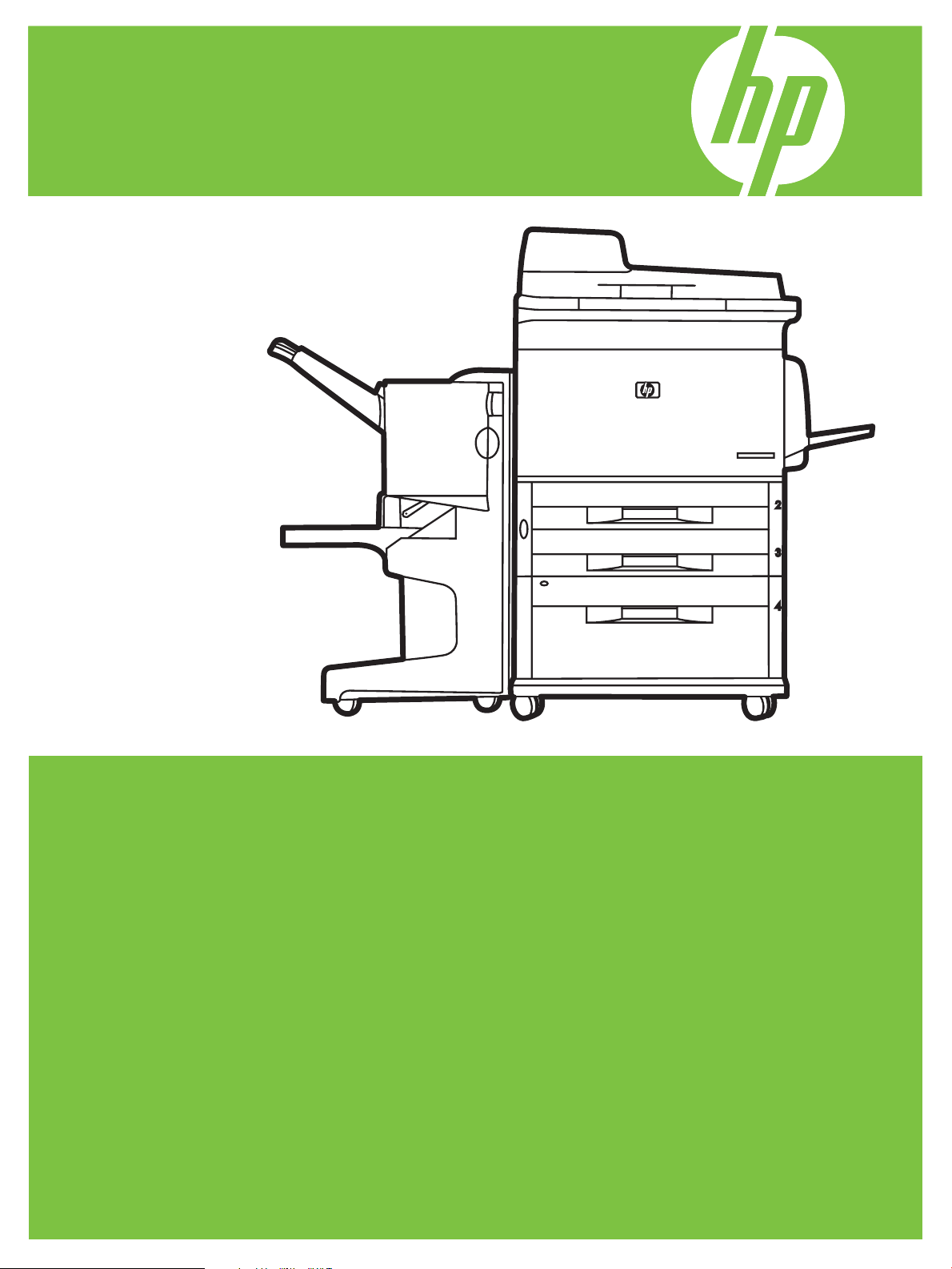
Product introduction
Figure 1-1 HP LaserJet M9059 MFP
The HP LaserJet M9059 MFP comes standard with the following items:
100-sheet multipurpose input tray (Tray 1)
●
Two 500-sheet input trays
●
One 2,000-sheet input tray
●
Automatic document feeder (ADF)
●
HP Jetdirect embedded print server for connecting to a 10/100/1000Base-TX network (Gigabit
●
support)
384 megabytes (MB) of random access memory (RAM)
●
Duplexer
●
Hard drive
●
2 Chapter 1 Product basics ENWW
Page 21

Product features
The HP LaserJet M9059 MFP is designed to be shared by a workgroup. The product is a standalone
copier that does not require connection to a computer. With the exception of network printing, you can
select all functions at the product control panel.
Functions
Two-sided copying and printing
●
Image modification
●
Color digital sending
●
Black-and-white printing and copying
●
Wide-format printing
●
Document finishing
●
Speed and throughput
40 ipm when scanning and printing on letter-size or ISO A4-size paper
●
25% to 400% scalability when using the scanner glass
●
25% to 200% scalability when using the automatic document feeder (ADF)
●
●
●
●
●
Resolution
●
●
●
Memory
●
●
User interface
●
Transmit Once, Raster Image Processing (RIP) ONCE technology
Eight-seconds to first page
Duty cycle of up to 300,000 images per month
533 megahertz (MHz) microprocessor
600 dots per inch (dpi) with Resolution Enhancement technology (REt)
FastRes 1200 provides 1200 dpi quality at full speed
Up to 256 levels of gray
384 megabytes (MB) of random-access memory (RAM), expandable to 512 MB by using industrystandard 100-pin double data rate dual inline memory modules (DDR DIMMs)
Memory Enhancement technology (MEt) that automatically compresses data to use RAM more
efficiently
Graphical display on control panel
Embedded Web server to gain access to support (for network-connected products)
●
ENWW Product features 3
Page 22

Language and fonts
HP Printer Command Language (PCL) 6
●
HP PCL 5e for compatibility
●
Printer Management Language
●
80 scalable TrueType typefaces
●
HP postscript level 3 emulation
●
Copying and sending
Modes for text, graphics, and mixed text and graphics formats
●
A job-interrupt feature (at copy boundaries)
●
Multiple pages per sheet
●
Operator attendance animations (for example, jam recovery)
●
The ability to copy books
●
E-mail compatibility
●
A sleep feature that saves energy
●
●
Print cartridge
●
●
●
Paper-handling
●
One-pass duplex scanning
No-shake cartridge design
Authentic HP print cartridge detection
Automatic seal-tab removal
Input
Tray 1 (multipurpose tray): A multipurpose tray for paper, transparencies, labels, and
◦
envelopes. Holds up to 100 sheets of paper or 10 envelopes.
Trays 2 and 3: Two 500-sheet trays. These trays automatically detect standard paper sizes
◦
up to 11 x 17/A3 and allow printing on custom-size paper.
Tray 4 (2000-sheet input tray): This tray automatically detects standard paper sizes up to
◦
11 x 17/A3 and allows printing on custom-size paper.
Automatic Document Feeder (ADF): Holds up to 100 sheets of Letter- or A4-size paper or
◦
50 sheets of 11 x 17- or A3-size paper.
Duplex printing: Provides two-sided printing (printing both sides of the paper).
◦
Output
●
4 Chapter 1 Product basics ENWW
Page 23

The product has the following optional output choices:
3000-sheet stacker: Stacks up to 3,000 sheets of paper.
◦
Upper bin (face up): Holds up to 100 sheets of paper.
Lower bin (face down): Holds up to 3,000 sheets of paper. The output bins are part of the
output device.
3000-sheet stapler/stacker: Provides multiposition stapling for up to 50 sheets of paper per
◦
job, or a maximum job height of 5 mm (0.2 in).
Upper bin (face up): Holds up to 100 sheets of paper.
Lower bin (face down): Holds up to 3,000 sheets of paper. The output bins are part of the
output device.
Multifunction finisher: Provides 1,000 sheets of stacking capacity, stapling for as many as
◦
50 sheets of paper per document, plus folding and saddle stitching of booklets that contain
up to 10 sheets of paper.
Upper bin (face up and face down): Holds up to 1,000 sheets of paper.
Lower booklet bin: Holds up to 50 booklets.
8-bin mailbox: A stacker, collator, or job separator that also provides eight mailbox bins that
◦
can be assigned to individual users or workgroups for easy identification and retrieval. The 8bin mailbox can stack up to 2,000 sheets of A4- or letter-size paper in all the bins.
Upper bin (face up): Holds up to 125 sheets of paper.
Bins 1 through 8 (face down): Each holds up to 250 sheets of paper.
Connectivity
Hi-Speed USB 2.0 connection
●
HP Jetdirect embedded print server.
●
Optional analog fax card
●
Optional HP Jetdirect EIO print server cards
●
HP Jetdirect 625n gigabit Ethernet internal print server
◦
Environmental features
To download the latest firmware, go to
●
onscreen instructions. To easily send firmware updates to multiple products, use the HP Web
Jetadmin software (go to
NOTE: HP Web Jetadmin 10.0 or later is required for full support of this product.
An internal hard disk can be used to store selected print jobs. It can support RIP ONCE technology
●
and can permanently store downloaded fonts and forms in the product. Many items on the hard
disk remain even when the product is turned off. Fonts on the hard disk are available to all users.
www.hp.com/go/ljm9059mfp_firmware and follow the
www.hp.com/go/webjetadmin).
An optional EIO hard disk accessory provides additional capacity for storing fonts and forms. The
●
product does not use the EIO hard disk accessory for tasks such as RIP ONCE and stored jobs.
ENWW Product features 5
Page 24

The product uses the internal hard disk for these tasks. Both disks can be write-protected through
software for additional security.
Security features
Secure Disk Erase
●
Security lock
●
Job retention
●
Front-panel authentication
●
6 Chapter 1 Product basics ENWW
Page 25
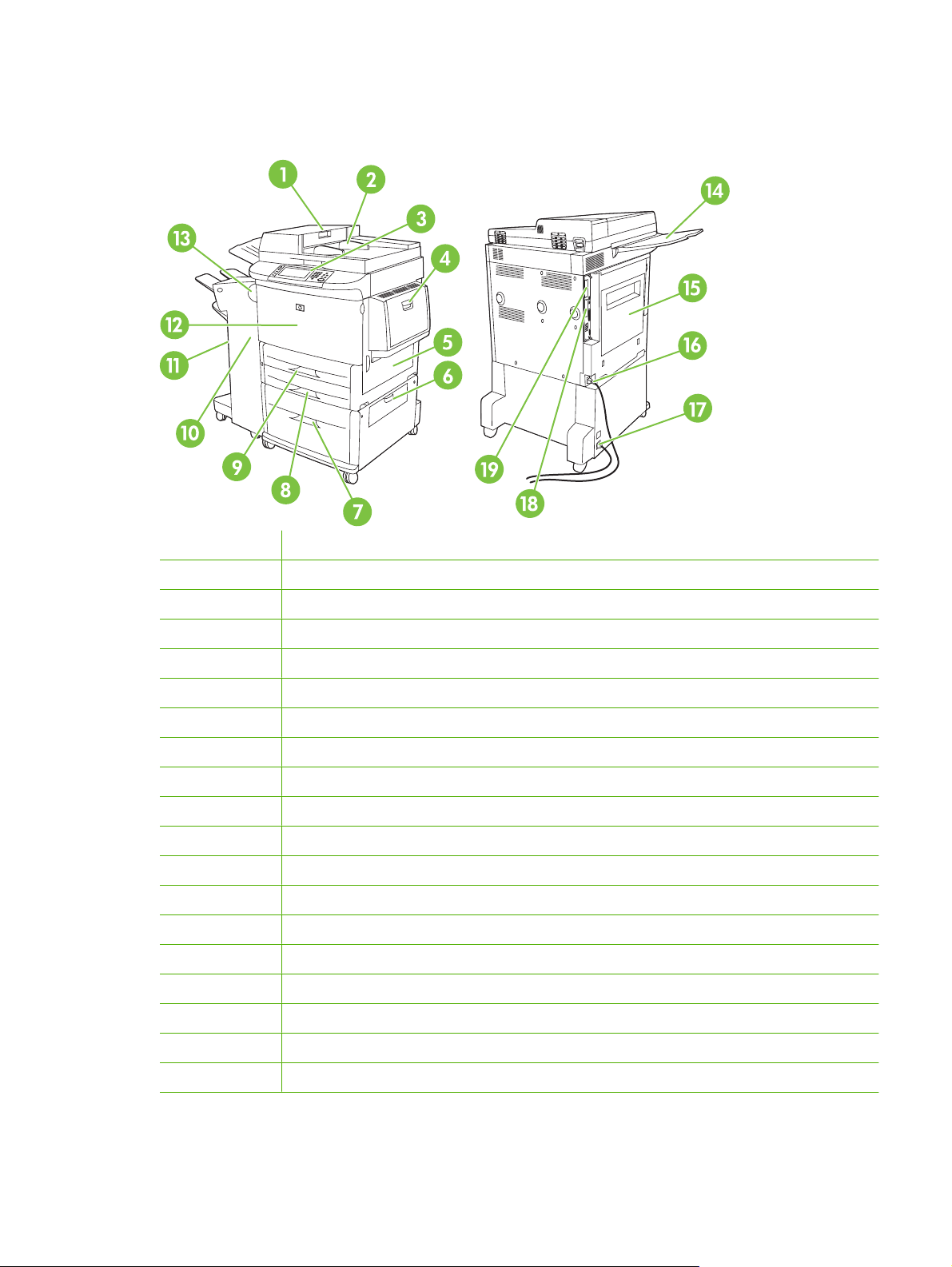
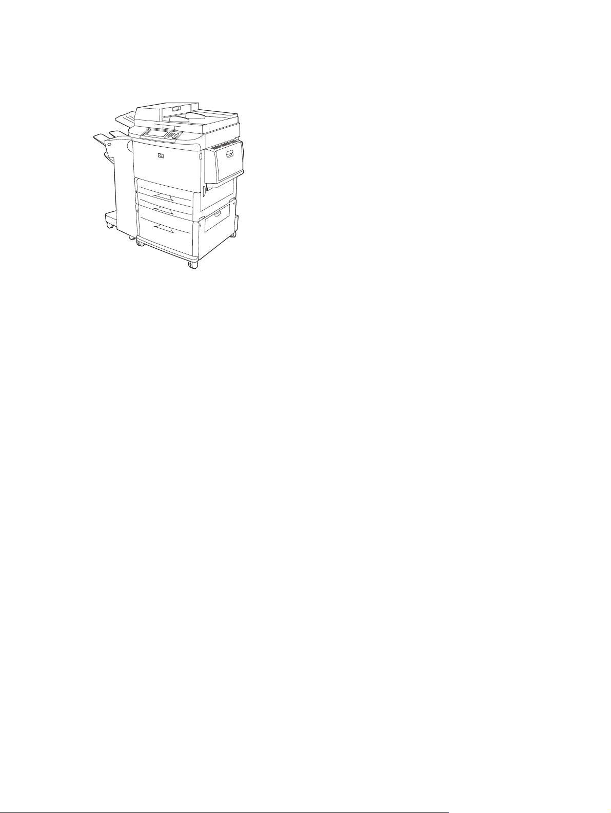
Product walkaround
Figure 1-2 Product walkaround
1 Automatic document feeder cover
2 Automatic document feeder (ADF)
3 Control panel with touchscreen graphical display
4 Tray 1
5 Right door
6 Vertical transfer door
7 Tray 4
8 Tray 3
9 Tray 2
10 Left door (behind output device)
11 Output device
12 Front door
13 Duplex printing accessory (inside the product)
14 ADF output bin
15 Left door
16 Printer power cable
17 Tray 4 power cable
18 EIO slot 1
19 Copy processor EIO card
ENWW Product walkaround 7
Page 26

Output devices
The following optional finishing devices are available for this product: 3,000-sheet stacker, 3,000-sheet
stapler/stacker, multifunction finisher, and 8-bin mailbox.
3,000-sheet stacker
Stacks up to 3,000 sheets of A4- or letter-size paper
●
Stacks up to 1,500 sheets of A3- or ledger-size paper
●
Can offset jobs, or offset the first page of jobs
●
The lower bin (face-down bin) is the default bin for all output jobs.
3,000-sheet stapler/stacker
Paper handling features
Stacks up to 3,000 sheets A4- or letter-size paper
●
Stacks up to 1,500 sheets of A3- or ledger-size paper
●
Can offset jobs, or offset the first page of jobs
●
The upper bin (face-up bin) is the default bin for all output jobs.
Stapling information
The 3,000-sheet stapler/stacker can staple 2 to 50 pages of 75 g/m2 (20 lb) paper or equivalent 5 mm
(0.2 in). The pages must be 64 to 199 g/m
Heavier media might have a stapling limit of fewer than 50 pages.
●
If the job is only one sheet, or, if it is more than 50 sheets, it is printed and not stapled.
●
You can usually select the stapler in the software program or print driver, although some options might
be available only in the print driver. See the product user guide for more information.
If the stapler cannot be selected in the program or printer driver, it can be selected through the product
control panel. See the product user guide for instructions.
Multifunction finisher
Paper handling features
Stacks up to 1,000 sheets of A4 and letter paper or up to 500 sheets of A3 and 11 x 17 paper
●
Stacks up to 40 booklets of 5 sheets of A3 and ledger paper
●
Can offset jobs
●
Staples up to 50 sheets of paper per document of A4 and letter paper
●
2
(17 to 53 lb) of all sizes that the device supports.
Staples up to 25 sheets of paper per document A3 and ledger paper
●
8 Chapter 1 Product basics ENWW
Page 27

Folds single pages
●
Saddle-stitches and folds up to 40 booklets of 5 sheets stacked, or 20 booklets of 10 sheets stacked
●
Stapling information
Booklets
The finisher can staple 2 to 50 pages of 75 g/m2 (20 lb) A-4 or letter-size paper or up to 25 pages of A3
11 x 17 paper or equivalent to 5.5 mm (0.22 in). The pages must be 64 to 199 g/m
sizes supported by the device.
Consider these additional points:
The upper bin (stacker bin) can hold up to 1,000 sheets stacked (not stapled). The multifunction
●
finisher can deliver jobs face up or face down to the upper bin.
Heavier media might have a stapling limit of fewer than 50 pages.
●
If the job is only one sheet, or, if it is more than 50 sheets, it is printed and not stapled.
●
You can usually select the stapler in the software program or print driver, although some options might
be available only in the print driver. See the product user guide for more information.
If the stapler cannot be selected in the program or print driver, it can be selected through the product
control panel. See the product user guide for instructions.
You can gain access to the booklet feature in some software programs, such as desktop publishing
programs. See the user guide that came with your program for information about making booklets.
If you are using a program that does not support booklet making, you can create booklets by using the
HP print driver.
2
(17 to 53 lb) of all
NOTE: HP recommends that you use your program to prepare and preview your document for printing,
and then use the HP print driver to print and saddle stitch your booklet.
Use the following steps to create a booklet by using the print driver:
Prepare your booklet: Arrange the pages on a sheet (called booklet imposition) to create a booklet.
●
You can impose your booklet in your software program, or you can use the booklet-printing feature
in print driver.
Add a cover: Add a cover for the first page by selecting a different paper type that is the same size
●
as the rest of the booklet. The cover can be a weight different from the rest of the booklet.
Use saddle stitching: Paper must be fed into the product short edge first. The product prompts you
●
for rotated paper. The multifunction finisher staples the center of your booklet (called saddle
stitching). If your booklet contains only one sheet of paper, the multifunction finisher folds the sheet
but does not staple it. If the booklet contains more than one sheet of paper, the multifunction finisher
staples the sheets and then folds up to 10 sheets per booklet.
The booklet-printing feature of the multifunction finisher supports the saddle stitch and fold feature for
the following paper sizes:
A3
●
A4-Rotated (A4-R)*
●
Letter-Rotated (Letter-R)*
●
ENWW Output devices 9
Page 28

●
●
Legal
Ledger
See the HP Multifunction Finisher User Guide at
about making booklets.
* A4-R and Letter-R are A4- and letter-size paper that is rotated 90˚ in the source tray.
8-bin mailbox
Handles high-capacity output that increases the product output capacity to 2,000 sheets of
●
standard media
Uses the upper bin to provide 125 sheets of face-up stacking capacity
●
Delivers printed jobs face down to the eight face down bins, and each bin provides 250 sheets of
●
stacking capacity
Offers stacking options in different operational modes: mailbox, stacker, job separator, and sorter/
●
collator
For more information about the 8-bin mailbox, see the user guide that came with the 8-bin mailbox.
www.hp.com/support/ljm9059mfp for more information
10 Chapter 1 Product basics ENWW
Page 29

2 Control panel
Use the control panel
●
Use the Administration menu
●
ENWW 11
Page 30
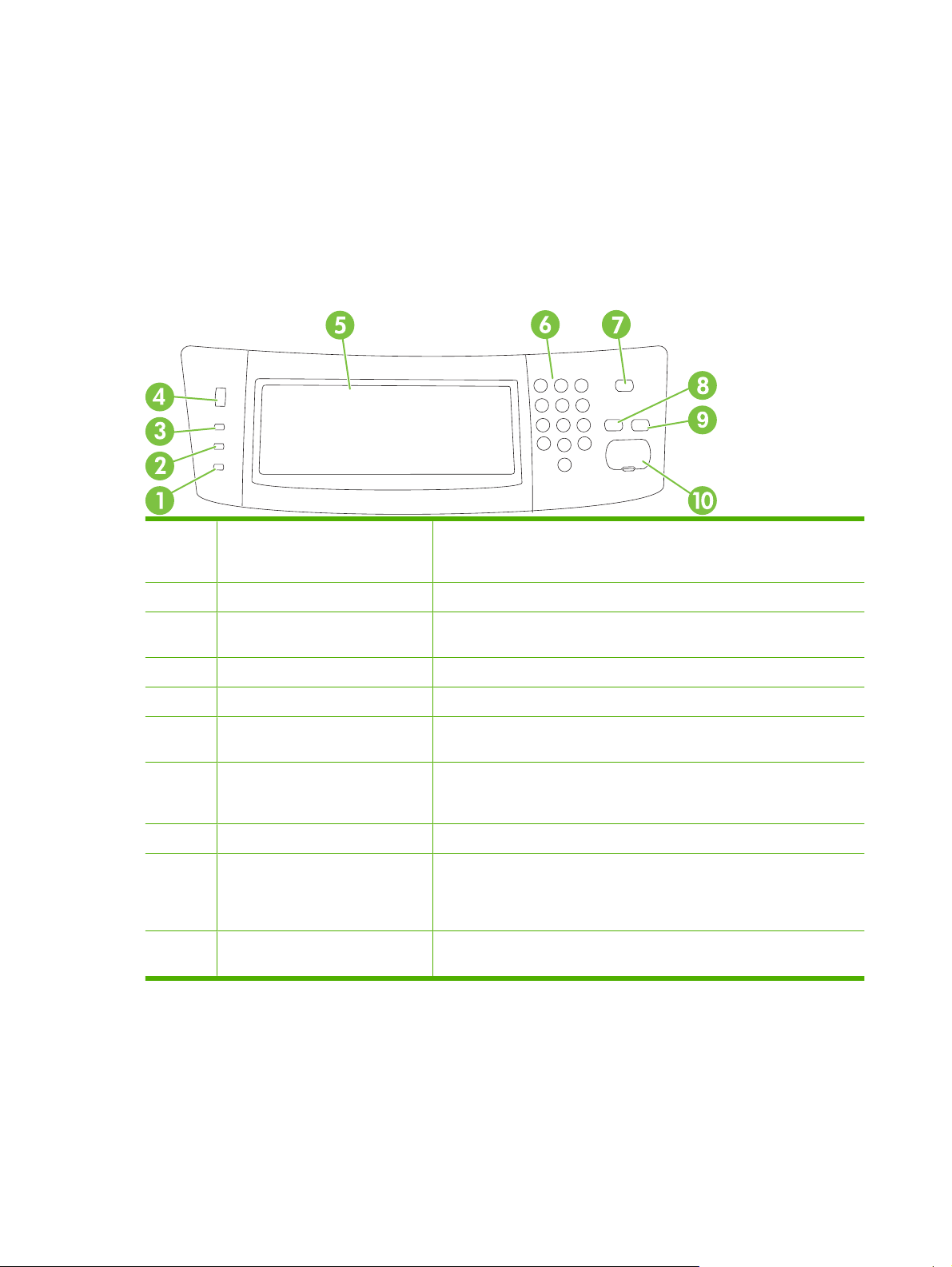
Use the control panel
The control panel has a VGA touchscreen that provides access to all product functions. Use the buttons
and numeric keypad to control jobs and the product status. The LEDs indicate overall product status.
Control-panel layout
The control panel includes a touchscreen graphical display, job-control buttons, a numeric keypad, and
three light-emitting diode (LED) status lights.
Figure 2-1 Control panel
1 Attention light The Attention light indicates that the product has a condition that requires
intervention. Examples include an empty paper tray or an error message
on the touchscreen.
2 Data light The Data light indicates that the product is receiving data.
3 Ready light The Ready light indicates that the product is ready to begin processing any
job.
4 Brightness-adjustment dial Roll the dial to control the brightness of the touchscreen.
5 Touchscreen graphical display Use the touchscreen to open and set up all product functions.
6 Numeric keypad Allows you to type numeric values for number of copies required and other
numeric values.
7 Sleep button If the product is inactive for a long period of time, it automatically enters a
8 Reset button Resets the job settings to factory default or user-defined default values.
9 Stop button Stops the active job. While stopped, the control panel shows the options for
10 Start button Begins a copy job, starts digital sending, or continues a job that has been
sleep mode. To place the product into sleep mode or to reactivate the
product, press the Sleep button.
the stopped job (for example, if you press the Stop button while the product
is processing a print job, the control panel message prompts you to cancel
or resume the print job).
interrupted.
12 Chapter 2 Control panel ENWW
Page 31

Home screen
The home screen provides access to the product features, and it indicates the current status of the
product.
NOTE: Depending on how the system administrator has configured the product, the features that
appear on the home screen can vary.
Figure 2-2 Home screen
1 Features Depending on how the system administrator has configured the product, the features that
appear in this area can include any of the following items:
Copy
●
Fax (Optional)
●
E-mail
●
Secondary E-mail
●
Network Folder
●
Job Storage
●
Workflow
●
Supplies Status
●
Administration
●
2 Status line The status line provides information about the overall product status. Various buttons appear
3 Copy count The copy count box indicates the number of copies that the product is set to make.
4 Help button Touch the Help button to open the embedded help system.
5 Scroll bar Touch the up or down arrows on the scroll bar to see the complete list of available features.
6 Sign Out Touch Sign Out to sign out of the product if you have signed in for access to restricted features.
7 Network Address Touch Network Address to find information about the network connection.
in this area, depending on the current status. For a description of each button that can appear
in the status line, see
After you sign out, the product restores all options to the default settings.
Buttons on the touchscreen on page 14.
8 Date and time The current date and time appear here. The system administrator can select the format that
the product uses to show the date and time, for example 12-hour format or 24-hour format.
ENWW Use the control panel 13
Page 32

Buttons on the touchscreen
The status line on the touchscreen provides information about the status of the product. Various buttons
can appear in this area. The following table describes each button.
Home button. Touch the Home button to go to the Home
screen from any other screen.
Start button. Touch the Start button to begin the action for the
feature that you are using.
NOTE: The name of this button changes for each feature. For
example, in the Copy feature, the button is named Start
Copy.
Error button. The Error button appears whenever the product
has an error that requires attention before it can continue.
Touch the Error button to see a message that describes the
error. The message also has instructions for solving the
problem.
Warning button. The Warning button appears when the
product has a problem but can continue functioning. Touch the
Warning button to see a message that describes the problem.
The message also has instructions for solving the problem.
Control-panel help system
The product has a built-in Help system that explains how to use each screen. To open the Help system,
touch the Help button (
For some screens, the Help opens to a global menu where you can search for specific topics. You can
browse through the menu structure by touching the buttons in the menu.
For screens that contain settings for individual jobs, the Help opens to a topic that explains the options
for that screen.
If the product alerts you of an error or warning, touch the Error (
message that describes the problem. The message also contains instructions to help solve the problem.
) in the upper-right corner of the screen.
Help button. Touch the Help button to open the built-in online
Help system. For more information, see
system on page 14.
Control-panel help
) or Warning ( ) button to open a
14 Chapter 2 Control panel ENWW
Page 33

Use the Administration menu
Use the Administration menu to set up default product behavior and other global settings, such as the
language and the format for date and time.
NOTE: Menus can be locked by the administrator. Contact the administrator if a menu or menu item
is not available.
Navigate the Administration menu
From the Home screen, touch Administration to open the menu structure. You might need to scroll to
the bottom of the Home screen to see this feature.
The Administration menu has several submenus, which are listed on the left side of the screen. Touch
the name of a menu to expand the structure. A plus sign (+) next to a menu name means that it contains
submenus. Continue opening the structure until you reach the option that you want to configure. To
return to the previous level, touch Back.
To exit the Administration menu, touch the Home button (
The product has built-in Help that explains each of the features that are available through the menus.
Help is available for many menus on the right-hand side of the touchscreen. Or, to open the global Help
system, touch the Help button (
The tables in the sections that follow indicate the overall structure of each menu.
) in the upper-right corner of the screen.
) in the upper-left corner of the screen.
ENWW Use the Administration menu 15
Page 34

Information menu
Administration > Information
Use this menu to print information pages and reports that are stored internally on the product.
Table 2-1 Information menu
Menu item Submenu item Submenu item Values Description
Configuration/Status
Pages
Fax Reports
(available only if the
fax accessory is
installed)
Administration Menu
Map
Configuration Page Print A set of configuration pages that show the
Supplies Status
Page
Usage Page Print Shows information about the number of
File Directory Print A directory page that contains information for
Fax Activity Log Print Contains a list of the faxes that have been
Fax Call Report Fax Call Report Print A detailed report of the last fax operation,
Thumbnail on Report Yes
When to Print Report Never auto print
Print Shows the basic structure of the
Administration menu and current
administration settings.
current product settings.
Print Shows the status of supplies such as
cartridges, maintenance kit, and staples
pages that have been printed on each paper
type and size.
any mass-storage devices, such as flash
drives, memory cards, or hard disks, that are
installed in this product
sent from or received by this product
either sent or received
Choose whether to include a thumbnail of the
first page of the fax on the report.
No (default)
Print after any fax job
Print after fax send jobs
Print after any fax error (default)
Print after send errors only
Print after receive errors only
Billing Codes Report
Blocked Fax List Print A list of phone numbers that are blocked from
Speed Dial List Print Shows the speed dials that have been set up
Sample Pages/Fonts PCL Font List Print A list of printer control language (PCL) fonts
PS Font List Print A list of postscript fonts that are currently
Print A list of billing codes that have been used for
outgoing faxes. This report shows how many
sent faxes were billed to each code.
sending faxes to this product
for this product
that are currently available on the product
available on the product
16 Chapter 2 Control panel ENWW
Page 35

Default Job Options menu
Administration > Default Job Options
Use this menu to define the default job options for each function. If the user does not specify the job
options when creating the job, the default options are used.
The Default Job Options menu contains the following submenus:
Default Options For Originals
●
Default Copy Options
●
Default Fax Options
●
Default E-mail Options
●
Default Send To Folder Options
●
Default Print Options
●
Default Options for Originals
Administration > Default Job Options > Default Options for Originals
NOTE: Values shown with “(default)” are the factory-default values. Some menu items have no default.
Table 2-2 Default Options for Originals menu
Menu item Values Description
Paper Size Select a paper size from the list. Select the paper size that is most often used for copy or scan
Number of Sides 1 (default) Select whether copy or scan originals are most often single-sided or
2
Orientation Portrait (default) Select the orientation that is most often used for copy or scan
Landscape
Optimize Text/Picture Manually Adjust (default) Use this setting to optimize the output for a particular type of original.
Text
Photograph
Image Adjustment Darkness Use this setting to optimize the output for darker or lighter originals
Background Cleanup Increase the Background Cleanup setting to remove faint images
Sharpness Adjust the Sharpness setting to clarify or soften the image.
Heavy Originals Normal
Heavy Paper
originals.
double-sided.
originals. Select Portrait if the short edge is at the top, or select
Landscape if the long edge is at the top.
You can optimize the output for text, pictures, or a mixture.
If you select Manually Adjust, you can specify the mix of text and
pictures that will most often be used.
that you scan or copy.
from the background or to remove a light background color.
This setting is important for jobs that use the ADF. Changing this
setting adjusts the tension on heavy paper as it moves through the
scanning area. It can affect output quality for papers that weigh more
than 100 g/m
2
.
ENWW Use the Administration menu 17
Page 36

Default Copy Options
Administration > Default Job Options > Default Copy Options
NOTE: Values shown with “(default)” are the factory-default values. Some menu items have no default.
Table 2-3 Default Copy Options menu
Menu item Submenu item Values Description
Number of Copies Type the number of
copies. The factory
default setting is 1.
Number of Sides 1 (default)
2
Staple/Collate Staple None (default)
Staple options
Collate Off
On (default)
Output Bin Bin numbers/name Select the default output bin, if applicable, for copies.
Edge-To-Edge Normal (recommended)
(default)
Edge-To-Edge Output
Auto Include Margins Off (default)
On
Set the default number of copies for a copy job.
Set the default number of sides for copies.
Set up options for stapling and collating sets of copies.
When you make multiple copies of a document,
collating places the pages in the correct order, one set
at a time, rather than placing all copies of each page
next to each other.
If the original document is printed close to the edges,
use the Edge-To-Edge feature to avoid shadows that
can appear along the edges. Combine this feature with
the Reduce/Enlarge feature to ensure that the entire
page is printed on the copies.
Select this feature to ensure that the entire image
appears on the copy, including any content that is close
to the edges. If necessary, the product shrinks the
image slightly, depending on the size of the printable
area on the paper.
18 Chapter 2 Control panel ENWW
Page 37

Default Fax Options
Administration > Default Job Options > Default Fax Options
NOTE: This menu is available when the fax accessory is installed.
Table 2-4 Fax Send menu
Menu item Submenu item Values Description
Resolution Standard (100x200dpi)
(default)
Fine (200x200dpi)
Superfine (300x300dpi)
Fax Header Prepend (default)
Overlay
Table 2-5 Fax Receive menu
Menu item Values Description
Forward Fax Fax Forwarding
Change PIN
Stamp Received Faxes Enabled
Disabled (default)
To forward received faxes to another fax device, select Fax
Forwarding and Custom. Then type the number of the other fax
device into the Forward to Number field. When you select this menu
item for the first time, you are prompted to set up a PIN. Type that
PIN every time you use this menu. This is the same PIN that is used
to access the Fax Printing menu. This PIN is exactly four digits.
Add the date, time, senders phone number, and page number to each
page of the faxes that this product receives.
Set the resolution for sent documents. Higher
resolution images have more dots per inch (dpi), so
they show more detail. Lower resolution images have
fewer dots per inch and show less detail, but the file
size is smaller.
Select the position of the fax header on the page.
Select Prepend to print the fax header above the fax
content and move the fax content down on the page.
Select Overlay to print the fax header over the top of
the fax contents without moving the contents down.
Using Overlay could prevent a single-page fax from
flowing onto another page.
Fit to Page Enabled (default)
Disabled
Fax Paper Tray Select Automatic or a specific
tray.
Output Bin <Binname> Select the default output bin, if applicable, to use for faxes.
Shrink faxes that are larger than Letter-size or A4-size so that they
can fit onto a Letter-size or A4-size page. If it this feature is set to
Disabled, faxes larger than Letter or A4 will flow across multiple
pages.
Select the tray that holds the size and type of paper that you want to
use for incoming faxes.
ENWW Use the Administration menu 19
Page 38

Default E-mail Options
Administration > Default Job Options > Default E-mail Options
Use this menu to set default options for e-mails that are sent from the product.
NOTE: Values shown with “(default)” are the factory-default values. Some menu items have no default.
Menu item Values Description
Document File Type PDF (default)
JPEG
TIFF
M-TIFF
Output Quality High (large file)
Medium (default)
Low (small file)
Resolution 300 DPI
200 DPI
150 DPI (default)
75 DPI
Color/Black Color scan (default)
Black/white scan
TIFF Version TIFF 6.0 (default)
TIFF (Post 6.0)
Choose the file format for the e-mail.
Choosing higher quality for output increases the size of the
output file.
Use this feature to select the resolution. Use a lower setting to
create smaller files.
Specify whether the e-mail will be in black or in color.
Use this feature to specify the TIFF version to use when saving
scanned files.
20 Chapter 2 Control panel ENWW
Page 39

Default Send to Folder Options
Administration > Default Job Options > Default Send to Folder Options
Use this menu to set default options for scan jobs sent to the computer.
NOTE: Values shown with “(default)” are the factory-default values. Some menu items have no default.
Menu item Values Description
Color/Black Color scan
Black/white scan (default)
Document File Type PDF (default)
M-TIFF
TIFF
JPEG
TIFF Version TIFF 6.0 (default)
TIFF (post 6.0)
Output Quality High (large file)
Medium (default)
Low (small file)
Resolution 75 DPI
150 DPI (default)
200 DPI
300 DPI
400 DPI
Specify whether the file will be in black or in color.
Choose the file format for the file.
Use this feature to specify the TIFF version to use when saving
scanned files.
Choosing higher quality for output increases the size of the
output file.
Use this feature to select the resolution. Use a lower setting to
create smaller files.
600 DPI
ENWW Use the Administration menu 21
Page 40

Default Print Options
Administration > Default Job Options > Default Print Options
Use this menu to set default options for jobs that are sent from a computer.
NOTE: Values shown with “(default)” are the factory-default values. Some menu items have no default.
Table 2-6 Default Print Options menu
Menu item Submenu item Values Description
Copies Per Job Type a value. Use this feature to set the default
number of copies for print jobs.
Default Paper Size (List of supported sizes) Choose a paper size.
Default Custom Paper
Size
Output Bin <Binname> Select the default output bin for print
Print Sides 1-sided (default)
2-Sided Format Long edge
Unit of measure Millimeters
Inches
X Dimension Configure the width measurement for
Y Dimension Configure the height measurement for
2-sided
Short edge
Configure the default paper size that is
used when the user selects Custom as
the paper size for a print job.
the Default Custom Paper Size.
the Default Custom Paper Size.
jobs.
Use this feature to select whether print
jobs should be single-sided or doublesided by default.
Use this feature to configure the default
style for 2-sided print jobs. If Long edge
is selected, the back side of the page is
printed the right way up. This option is for
print jobs that are bound along the left
edge. If Short edge is selected, the back
side of the page is printed upside-down.
This option is for print jobs that are
bound along the top edge.
22 Chapter 2 Control panel ENWW
Page 41

Time/Scheduling menu
Administration > Time/Scheduling
Use this menu to set options for setting the time and for setting the product to enter and exit sleep
mode.
NOTE: Values shown with "(default)" are the factory-default values. Some menu items have no default.
Table 2-7 Time/Scheduling menu
Menu item Submenu item Submenu item Values Description
Date/Time Date Format YYYY/MMM/DD
Date Month
Day
Year
Time Format 12 hour (AM/PM)
Time Hour
Minute
AM
PM
Time Zone Use this feature to set the time zone for your
(default)
MMM/DD/YYYY
DD/MMM/YYYY
(default)
24 hour
Use this feature to set the current date and
time, and to set the date format and time
format that are used to time-stamp outgoing
faxes.
location and to select whether the product
should automatically adjust for daylightsaving time.
Sleep Delay 1 Minute
20 minutes
30 minutes
45 minutes (default)
1 hour (60 minutes)
90 minutes
2 hours
4 hours
Use this feature to select the time interval that
the product should remain inactive before
entering sleep mode.
ENWW Use the Administration menu 23
Page 42

Table 2-7 Time/Scheduling menu (continued)
Menu item Submenu item Submenu item Values Description
Wake Time Monday
Tuesday
Wednesday
Thursday
Friday
Saturday
Sunday
Sleep Time Monday
Tuesday
Wednesday
Thursday
Friday
Saturday
Sunday
Fax Printing
(available if the fax
accessory is
installed)
Fax Printing Mode Store all received
Off (default)
Custom
Off (default)
Custom
faxes
Print all received
faxes (default)
Use Fax Printing
Schedule
Select Custom to set a wake time for each
day of the week. The product exits sleep
mode according to this schedule. Using a
sleep schedule helps conserve energy and
prepares the product for use so that users do
not have to wait for it to warm up.
Select Custom to set a sleep time for each
day of the week. The product is put in sleep
mode according to this schedule. Using a
sleep schedule helps conserve energy.
If you have concerns about the security of
private faxes, use this feature to store faxes
rather than having them automatically print by
creating a printing schedule.
For the fax printing schedule, the control
panel prompts you to select days and times
to print faxes.
Change PIN
Select Change PIN to change the PIN
number that users must provide to access the
Fax Printing menu and the Forward Fax
menu. This PIN is exactly four digits.
24 Chapter 2 Control panel ENWW
Page 43

Management menu
Administration > Management
Use this menu to set up global product-management options.
NOTE: Values shown with "(default)" are the factory-default values. Some menu items have no default.
Table 2-8 Management menu
Menu item Submenu item Values Description
Network Address Button Display (default)
Hide
Stored Job Management Quick Copy Job Storage
Limit
Quick Copy Job Held
Timeout
Sleep mode Disable
Manage Supplies Replace Black Cartridge Stop at low
Supply Low/Order
Threshold
Select the maximum
number of jobs to store.
Off (default)
1 Hour
4 hours
1 Day
1 Week
Use Sleep Delay (default)
Stop at out
Override at out (default)
Select a value in the
range.
Select this option to display the Network Address
button on the control-panel home screen.
Use this menu to view and manage any jobs that are
stored on the product.
Use this feature to customize the sleep mode settings
for this product.
Select Use Sleep Delay to set the product to enter
sleep mode after the delay that is specified in the Time/
Scheduling menu.
Use this menu to carry out administrative supply
management tasks such as changing the threshold
when supplies should be ordered.
ENWW Use the Administration menu 25
Page 44

Initial Setup menu
Administration > Initial Setup
The Initial Setup menu contains the submenus shown:
Networking and I/O menu
●
Fax Setup menu
●
E-mail Setup menu
●
NOTE: Values shown with "(default)" are the factory-default values. Some menu items have no default.
Networking and I/O
Administration > Initial Setup > Networking and I/O
Table 2-9 Networking and I/O
Menu item Submenu item Values Description
I/O Timeout Select a value in the
range. The factory default
setting is 15 seconds.
Embedded Jetdirect See Table 2-10 Jetdirect menus on page 26 for the list of options.
EIO <X> Jetdirect
Table 2-10 Jetdirect menus
Menu item Submenu item Submenu item Values and Description
TCP/IP Enable Off: Disable the TCP/IP protocol.
Host Name An alphanumeric string, up to 32 characters, used to
I/O timeout refers to the elapsed time before a print job
fails. If the stream of data that the product receives for
a print job gets interrupted, this setting indicates how
long the product will wait before it reports that the job
has failed.
On (default): Enable the TCP/IP protocol.
identify the product. This name is listed on the
HP Jetdirect configuration page. The default host name
is NPIxxxxxx, where xxxxxx is the last six digits of the
LAN hardware (MAC) address.
26 Chapter 2 Control panel ENWW
Page 45

Table 2-10 Jetdirect menus (continued)
Menu item Submenu item Submenu item Values and Description
IPV4 Settings Config Method Specifies the method by which TCP/IPv4 parameters
for the HP Jetdirect print server will be configured.
Bootp: Use BootP (Bootstrap Protocol) for automatic
configuration from a BootP server.
DHCP (Default): Use DHCP (Dynamic Host
Configuration Protocol) for automatic configuration
from a DHCPv4 server. If selected and a DHCP lease
exists, DHCP Release and DHCP Renew menus are
available to set DHCP lease options.
Auto IP: Use automatic link-local IPv4 addressing. An
address in the form 169.254.x.x is assigned
automatically.
Manual: Use the Manual Settings menu to configure
TCP/IPv4 parameters.
DHCP Release This menu appears if Config Method was set to
DHCP Renew This menu appears if Config Method was set to
Manual Settings (Available only if Config Method is set to Manual)
DHCP and a DHCP lease for the print server exists.
No (default): The current DHCP lease is saved.
Yes: Release the current IP address. Note that the
printer will lose network connectivity until it reboots at
which point it may have a new address.
DHCP and a DHCP lease for the print server exists.
No (default): The print server does not request to renew
the DHCP lease.
Yes: The print server renews the lease on its IP
address.
Configure parameters directly from the printer control
panel:
IP Address: The unique IP address of the printer
(n.n.n.n), where n is a value from 0 to 255.
Subnet Mask: The subnet mask for the printer
(m.m.m.m), where m is a value from 0 to 255.
Syslog Server: The IP address of the syslog server
used to receive and log syslog messages.
Default Gateway: The IP address of the gateway or
router used for communications with other networks.
Idle Timeout: The time period, in seconds, after which
an idle TCP print data connection is closed (default is
270 seconds, 0 disables the timeout).
ENWW Use the Administration menu 27
Page 46

Table 2-10 Jetdirect menus (continued)
Menu item Submenu item Submenu item Values and Description
Default IP Specify the IP address to default to when the print
server is unable to obtain an IP address from the
network during a forced TCP/IP reconfiguration (for
example, when manually configured to use BootP or
DHCP).
Auto IP: A link-local IP address 169.254.x.x is set.
Legacy: The address 192.0.0.192 is set, consistent
with older HP Jetdirect devices.
Primary DNS Specify the IP address (n.n.n.n) of a Primary DNS
Secondary DNS Specify the IP address (n.n.n.n) of a Secondary
IPV6 Settings Enable Use this item to enable or disable IPv6 operation on the
Address Use this item to manually configure an IPv6 address.
DHCPV6 Policy Router Specified (Default): The stateful auto-
Server.
Domain Name System (DNS) Server.
print server.
Off (default): IPv6 is disabled.
On: IPv6 is enabled.
Manual Settings: Use the Manual Settings menu to
enable and manually configure a TCP/ IPv6 address.
configuration method to be used by the print server is
determined by a router. The router specifies whether
the print server obtains its address, its configuration
information, or both from a DHCPv6 server.
Router Unavailable: If a router is not available, the print
server should attempt to obtain its stateful
configuration from a DHCPv6 server.
Always: Whether or not a router is available, the print
server always attempts to obtain its stateful
configuration from a DHCPv6 server.
Primary DNS Use this item to specify an IPv6 address for a primary
DNS server that the print server should use.
Manual Settings Use this item to manually set IPv6 addresses on the
print server.
Enable: Select this item and choose On to enable
manual configuration, or Off to disable manual
configuration.
Address: Use this item to type a 32 hexadecimal digit
IPv6 node address that uses the colon hexadecimal
syntax.
28 Chapter 2 Control panel ENWW
Page 47

Table 2-10 Jetdirect menus (continued)
Menu item Submenu item Submenu item Values and Description
Proxy Server Specifies the proxy server to be used by embedded
applications in the product. A proxy server is typically
used by network clients for Internet access. It caches
Web pages and provides a degree of Internet security
for those clients.
To specify a proxy server, enter its IPv4 address or
fully-qualified domain name. The name can be up to
255 octets.
For some networks, you may need to contact your
Independent Service Provider (ISP) for the proxy
server address.
Proxy Port Type the port number used by the proxy server for
IPX/SPX Enable Off: Disable the IPX/SPX protocol.
Frame Type Selects the frame-type setting for your network.
A Talk Enable Off : Disable the AppleTalk protocol.
DLC/LLC Enable Off : Disable the DLC/LLC protocol.
client support. The port number identifies the port
reserved for proxy activity on your network, and can be
a value from 0 to 65535.
On (default): Enable the IPX/SPX protocol.
Auto (Default): Automatically sets and limits the frame
type to the first one detected.
EN_8023, EN_II, EN_8022, and EN_SNAP: Frame-
type selections for Ethernet networks.
On (default): Enable the AppleTalk protocol.
On (default): Enable the DLC/LLC protocol.
ENWW Use the Administration menu 29
Page 48

Table 2-10 Jetdirect menus (continued)
Menu item Submenu item Submenu item Values and Description
Security Print Sec Page Yes: Prints a page that contains the current security
settings on the HP Jetdirect print server.
No (default): A security settings page is not printed.
Secure Web For configuration management, specify whether the
IPsec or Firewall Specify the IPsec or Firewall status on the print server.
Reset Security Specify whether the current security settings on the
embedded Web server will accept communications
using HTTPS (Secure HTTP) only, or both HTTP and
HTTPS.
HTTPS Required (Default): For secure, encrypted
communications, only HTTPS access is accepted. The
print server will appear as a secure site.
HTTP/HTTPS optional: Access using either HTTP or
HTTPS is permitted.
Keep: IPsec/Firewall status remains the same as
currently configured.
Disable (Default): IPsec/Firewall operation on the print
server is disabled.
print server will be saved or reset to factory defaults.
No (default): The current security settings are
maintained.
Yes: Security settings are reset to factory defaults.
30 Chapter 2 Control panel ENWW
Page 49

Table 2-10 Jetdirect menus (continued)
Menu item Submenu item Submenu item Values and Description
Diagnostics Embedded Tests This menu provides tests to help diagnose network
hardware or TCP/IP network connection problems.
Embedded tests help to identify whether a network fault
is internal or external to the product. Use an embedded
test to check hardware and communication paths on
the print server. After you select and enable a test and
set the execution time, you must select Execute to
initiate the test.
Depending on the execution time, a selected test runs
continuously until either the product is turned off, or an
error occurs and a diagnostic page is printed.
LAN HW Test CAUTION: Running this embedded test will erase
HTTP Test This test checks operation of HTTP by retrieving
SNMP Test This test checks operation of SNMP communications
Select All Tests Use this item to select all available embedded tests.
Data Path Test This test helps to identify data path and corruption
your TCP/IP configuration.
This test performs an internal loopback test. An internal
loopback test will send and receive packets only on the
internal network hardware. There are no external
transmissions on your network.
Select Yes to choose this test, or No to not choose it.
predefined pages from the product, and tests the
embedded Web server.
Select Yes to choose this test, or No to not choose it.
by accessing predefined SNMP objects on the product.
Select Yes to choose this test, or No to not choose it.
Select Yes to choose all tests. Select No to select
individual tests.
problems on an HP PostScript Emulation Universal
Print Driver. It sends a predefined file to the product,
However, the test is paperless; the file will not print.
Select Yes to choose this test, or No to not choose it.
Execution Time [H] Use this item to specify the length of time (in hours) that
Execute No: Do not initiate the selected tests.
an embedded test will be run. You can select a value
from 1 to 60 hours. If you select zero (0), the test runs
indefinitely until an error occurs or the product is turned
off.
Data gathered from the HTTP, SNMP, and Data Path
tests is printed after the tests have completed.
Yes: Initiate the selected tests.
ENWW Use the Administration menu 31
Page 50

Table 2-10 Jetdirect menus (continued)
Menu item Submenu item Submenu item Values and Description
Ping Test This test is used to check network communications.
This test sends link-level packets to a remote network
host, then waits for an appropriate response. To run a
ping test, set the following items:
Dest Type Specify whether the target product is an IPv4 or IPv6
node.
Dest IP IPV4: Type the IPv4 address.
IPV6: Type the IPv6 address.
Packet Size Specify the size of each packet, in bytes, to be sent to
the remote host. The minimum is 64 (default) and the
maximum is 2048.
Timeout Specify the length of time, in seconds, to wait for a
response from the remote host. The default is 1 and
the maximum is 100.
Count Specify the number of ping test packets to send for this
Print Results If the ping test was not set for continuous operation,
Execute Specify whether to initiate the ping test. Select Yes to
test. Select a value from 1 to 100. To configure the test
to run continuously, select 0.
you can choose to print the test results. Select Yes to
print results. If you select No (default), results are not
printed.
initiate the test, or No to not run the test.
32 Chapter 2 Control panel ENWW
Page 51

Table 2-10 Jetdirect menus (continued)
Menu item Submenu item Submenu item Values and Description
Ping Results Use this item to view the ping test status and results
using the control panel display. You can select the
following items:
Packets Sent Shows the number of packets (0 - 65535) sent to the
Packets Received Shows the number of packets (0 - 65535) received from
Percent Lost Shows the percent of ping test packets that were sent
RTT Min Shows the minimum detected round-trip time (RTT),
RTT Max Shows the maximum detected round-trip time (RTT)
RTT Average Shows the average round-trip-time (RTT), from 0 to
Ping In Progress Shows whether a ping test is in progress. Yes indicates
Refresh When viewing the ping test results, this item updates
remote host since the most recent test was initiated or
completed.
the remote host since the most recent test was initiated
or completed.
with no response from the remote host since the most
recent test was initiated or completed.
from 0 to 4096 milliseconds, for packet transmission
and response.
from 0 to 4096 milliseconds for packet transmission
and response.
4096 milliseconds for packet transmission and
response.
a test in progress, and No indicates that a test
completed or was not run.
the ping test data with current results. Select Yes to
update the data, or No to maintain the existing data.
However, a refresh automatically occurs when the
menu times out or you manually return to the main
menu.
ENWW Use the Administration menu 33
Page 52

Table 2-10 Jetdirect menus (continued)
Menu item Submenu item Submenu item Values and Description
Link Speed The link speed and communication mode of the print
server must match the network. The available settings
depend on the product and installed print server. Select
one of the following link configuration settings:
CAUTION: If you change the link setting, network
communications with the print server and network
device might be lost.
Auto (default): The print server uses auto-negotiation
to configure itself with the highest link speed and
communication mode allowed. If auto-negotiation fails,
either 100TX HALF or 10TX HALF is set depending on
the detected link speed of the hub/switch port. (A
1000T half-duplex selection is not supported.)
10T Half: 10 Mbps, half-duplex operation
10T Full: 10 Mbps, full-duplex operation
100TX Half: 100 Mbps, half-duplex operation
100TX Full: 100 Mbps, full-duplex operation
100TX Auto: Limits auto-negotiation to a maximum link
speed of 100 Mbps.
1000TX Full: 1000 Mbps, full-duplex operation
Print Protocols Use this item to print a page that lists the configuration
of the following protocols: IPX/SPX, Novell NetWare,
AppleTalk, DLC/LLC.
34 Chapter 2 Control panel ENWW
Page 53

Fax Setup
Administration > Initial Setup > Fax Setup
NOTE: This menu is available if the fax accessory is installed.
Table 2-11 Fax Setup menu
Menu item Submenu item Submenu item Values Description
Required Settings Country/Region (Countries/regions
listed)
Date/Time
Fax Header
Information
PC Fax Send Disabled
Phone Number
Company Name
Enabled (default)
Configure the settings that are legally
required for outgoing faxes.
Use this feature to enable or disable PC Fax
Send. PC Fax Send enables users to send
faxes through the product from their
computers if they have the Send Fax driver
installed.
ENWW Use the Administration menu 35
Page 54

Table 2-11 Fax Setup menu (continued)
Menu item Submenu item Submenu item Values Description
Fax Send Settings Fax Dial Volume Off
Low (default)
High
Error Correction
Mode
JBIG Compression Enabled (default)
Maximum Baud Rate Select a value from
TCF T.30 Delay
Timer
TCF Extend Default (default)
Enabled (default)
Disabled
Disabled
the list. The default is
33.6K.
Default (default)
Custom
Custom
Use this feature to set the volume of the tones
that you hear while the product dials the fax
number.
When Error Correction Mode is enabled and
an error occurs during fax transmission, the
product sends or receives the error portion
again.
JBIG compression reduces fax-transmission
time, which can result in lower phone
charges. However, using JBIG compression
sometimes causes compatibility problems
with older fax machines. If this occurs, turn off
JBIG compression.
Use this feature to set the maximum baud
rate for receiving faxes. This can be used as
a diagnostic tool for troubleshooting fax
problems.
This setting should be left at the default value
and only changed when directed by an
HP technical support agent. Adjustment
procedures associated with this setting are
beyond the scope of this guide.
This setting should be left at the default value
and only changed when directed by an HP
technical support agent. Adjustment
procedures associated with this setting are
beyond the scope of this guide.
Dialing Mode Tone (default)
Pulse
Redial On Busy The range is between
0 and 9. The factory
default is 3 times.
Redial On No Answer Never (default)
Once
Twice
Select whether the product should use tone
or pulse dialing.
Type the number of times the product should
attempt to redial if the line is busy.
Use this feature to specify the number of
times the product should attempt to dial if the
recipient fax number does not answer.
NOTE: Twice is available in locations other
than the United States and Canada.
36 Chapter 2 Control panel ENWW
Page 55

Table 2-11 Fax Setup menu (continued)
Menu item Submenu item Submenu item Values Description
Redial Interval The range is between
1 and 5 minutes. The
factory default is 5
minutes.
Detect Dial Tone Enabled
Disabled (default)
Dialing Prefix Off (default)
Custom
Billing Codes Off (default)
Custom
Fax Receive Settings Rings To Answer The range varies by
location. The factory
default is 2 rings.
Ring Interval Default (default)
Custom
Ring Frequency Default (default)
Custom
Use this feature to specify the number of
minutes between dialing attempts if the
recipient number is busy or not answering.
Use this feature to specify whether the
product should check for a dial tone before
sending a fax.
Use this feature to specify a prefix number
that must be dialed when sending faxes from
the product.
When billing codes are enabled, a prompt
appears that asks the user to enter the billing
code for an outgoing fax.
The range is between 1 and 16 digits. The
default is 1 digit.
Use this feature to specify the number of rings
that must occur before the fax modem
answers.
This setting is used to adjust for some PBX
ring signals. Change this setting only when
directed by an HP technical support agent.
This setting should be left at the default value
and only changed when directed by an
HP technical support agent. Adjustment
procedures associated with this setting are
beyond the scope of this guide.
Ringer Volume Off
Low (default)
High
Blocked Fax
Numbers
Add Blocked
Numbers
Remove Blocked
Numbers
Clear All Blocked
Numbers
Type the fax number
to add.
Select a fax number
to remove.
No (default)
Yes
Set the volume for the fax ring-tone.
Use this feature to add or delete numbers
from the blocked fax list. The blocked fax list
can contain up to 30 numbers. When the
product receives a call from one of the
blocked fax numbers, it deletes the incoming
fax. It also logs the blocked fax in the activity
log along with job-accounting information.
ENWW Use the Administration menu 37
Page 56

E-mail Setup
Administration > Initial Setup > E-mail Setup
Use this menu to enable the e-mail feature and to configure basic e-mail settings.
NOTE: To configure advanced e-mail settings, use the embedded Web server. For more information,
Embedded Web server on page 68.
see
Table 2-12 E-mail Setup menu
Menu item Values Description
Address Validation On (default)
Off
Find Send Gateways Search the network for SMTP gateways that the product can use to
SMTP Gateway Enter a value. Specify the IP address of the SMTP gateway that is used to send e-
Test Send Gateway Test the configured SMTP gateway to see if it is functional.
This option enables the product to check e-mail syntax when you type
an e-mail address. Valid e-mail addresses require the "@" sign and
a dot (.).
send e-mail.
mail from the product.
Send Setup menu
Administration > Initial Setup > Send Setup
Table 2-13 Send Setup menu
Menu item Values Description
Replicate MFP Enter a value (IP Address). Copy the local Send settings from one product to another.
Allow Transfer to New DSS Off
On (default)
Use this feature to allow the transfer of the product from one
HP Digital Sending Software (DSS) server to another.
HP DSS is a software package that handles digital sending tasks such
as faxing, e-mail, and sending a scanned document to a network
folder.
Allow Use of Digital Send Service Off
On (default)
Fax Number Confirmation Disable (default)
Enable
Fax Number Speed Dial
Matching
Disable (default)
Enable
This feature allows you to configure the product for use with an
HP Digital Sending Software (DSS) server.
Enable fax number confirmation for fax numbers that are entered at
the product control panel. When fax number confirmation is enabled,
the fax number must be entered twice to ensure that it was entered
correctly.
If this feature is enabled, the product tries to match any fax number
entered with existing entries in the speed dial list. If a match is found,
you can confirm the match and have the product complete the faxing
action automatically.
38 Chapter 2 Control panel ENWW
Page 57

Device Behavior menu
Administration > Device Behavior
NOTE: Values shown with "(default)" are the factory-default values. Some menu items have no default.
Table 2-14 Device Behavior menu
Menu item Submenu item Submenu item Values Description
Language Select the language
Key Press Sound On (default)
Inactivity Timeout Type a value
Warning/Error
Behavior
Tray Behavior Use Requested Tray Exclusively (default)
Clearable Warnings On
Continuable Events Auto continue (10
Jam Recovery Auto (default)
from the list.
Off
between 10 and 300
seconds. The factory
default is 60
seconds.
Job (default)
seconds) (default)
Press OK to continue
On
Off
First
Use this feature to select a different language
for control-panel messages. When you select
a new language, the keyboard layout might
also change.
Use this feature to specify whether you hear
a sound when you touch the screen or press
buttons on the control panel.
Use this feature to specify the amount of time
that elapses between any activity on the
control panel and the product resetting to the
default settings.
Use this feature to set the amount of time that
a clearable warning appears on the control
panel.
Use this option to configure the product
behavior when the product encounters
certain errors.
Use this feature to configure how the product
handles pages that are lost during a jam.
Use this feature to control how the product
handles jobs that have specified a specific
input tray.
Manually Feed
Prompt
PS Defer Media Enabled (default)
Use Another Tray Enabled (default)
Size/Type Prompt Display
Duplex Blank Pages Auto (default)
Always (default)
Unless Loaded
Disabled
Disabled
Do not display
(default)
Yes
Use this feature to indicate whether a prompt
should appear when the type or size for a job
does not match the specified tray and the
product pulls from the multipurpose tray
instead.
Use this feature to choose either the
postscript or HP paper-handling model.
Use this feature to turn on or off the controlpanel prompt to select another tray when the
specified tray is empty.
Use this feature to control whether the tray
configuration message appears whenever a
tray is opened or closed.
Use this feature to control how the product
handles two-sided jobs (duplexing).
ENWW Use the Administration menu 39
Page 58

Table 2-14 Device Behavior menu (continued)
Menu item Submenu item Submenu item Values Description
[output device menu]
NOTE: This menu
varies depending on
the output device
installed.
General Copy
Behavior
Auto Print Interrupt Enabled
Copy Interrupt Enabled
Use this menu to set the finishing options for
Hold Off Print Job On
Off
Hold Off Time Prevents non-copy print jobs from starting for
Scan Ahead Enabled (default)
Disabled
Disabled (Default)
Disabled (Default)
the installed output device.
Prevents print jobs from beginning to print
while a walk-up user is setting up a job.
a specified time after a copy job is completely
printed.
Use this feature to turn on no-wait scanning.
With Scan Ahead enabled, the pages in the
original document are scanned to disk and
held until the product becomes available.
When this feature is enabled, copy jobs can
interrupt print jobs that are set to print multiple
copies.
The copy job is inserted into the print queue
at the end of one copy of the print job. After
the copy job is complete, the product
continues printing the remaining copies of the
print job.
When this feature is enabled, a copy job that
is currently printing can be interrupted when
a new copy job is started. You are prompted
to confirm that you want to interrupt the
current job.
Alternative
Letterhead Mode
Off (default)
On
Enable this feature to load letterhead or
preprinted paper into the tray the same way
for all copy jobs, whether you are copying to
one side of the sheet or to both sides of the
sheet. When this option is selected, load the
paper as you would for printing on both sides.
The product speed slows to the speed
required for printing on both sides.
40 Chapter 2 Control panel ENWW
Page 59

Table 2-14 Device Behavior menu (continued)
Menu item Submenu item Submenu item Values Description
General Printing
Behavior
Override A4/Letter No
Yes (default)
Manual Feed Enabled
Disabled (default)
Edge-To-Edge
Override
Courier Font Regular (default)
Wide A4 Enabled
Print PS Errors Enabled
Print PDF Errors Enabled (default)
Enabled
Disabled (default)
Dark
Disabled (default)
Disabled (default)
Disabled
Use this feature to print on letter-size paper
when an A4 job is sent but no A4-size paper
is loaded in the product (or to print on A4
paper when a letter-size job is sent but no
letter-size paper is loaded). This option will
also override A3 with ledger-size paper and
ledger with A3-size paper.
When this feature is enabled, the user can
select manual feed from the control panel as
the paper source for a job.
Use the feature to turn the edge-to-edge
mode on or off for all print jobs. This mode
can be overridden inside a print job by an
edge-to-edge PJL variable.
Use this feature to select which version of the
Courier font you want to use.
Use this feature to change the printable area
of A4-size paper. If you enable this option,
eighty 10-pitch characters can be printed on
a single line of A4 paper.
Use this feature to select whether a postscript
(PS) error page is printed when the product
encounters a PS error.
Use this feature to select whether a PDF error
page is printed when the product encounters
a PDF error.
Personality Auto (default)
PCL
PDF
PS
Select the printer language that the product
should use.
Normally you should not change the
language. If you change the setting to a
specific language, the product does not
automatically switch from one language to
another unless specific software commands
are sent to the product.
ENWW Use the Administration menu 41
Page 60

Table 2-14 Device Behavior menu (continued)
Menu item Submenu item Submenu item Values Description
PCL Form Length Type a value
between 5 and 128
lines. The factory
default is 60 lines.
Orientation Portrait (default)
Landscape
Font Source Select the source
from the list.
Font Number Type the font
number. The range is
between 0 and 999.
The factory default is
0.
Font Pitch Type a value
between 0.44 and
99.99. The factory
default is 10.00.
Font Point Size Type a value
between 4.00 and
999.75. The factory
default is 12.00.
PCL is a set of printer commands that
Hewlett-Packard developed to provide
access to printer features.
Select the orientation that is most often used
for print jobs. Select Portrait if the short edge
is at the top, or select Landscape if the long
edge is at the top.
Use this feature to select the font source for
the user-defined soft default font.
Use this feature to specify the font number for
the user-soft default font using the source that
is specified in the Font Source menu item.
The product assigns a number to each font
and lists it on the PCL font list (available from
the Administration menu).
If Font Source and Font Number indicate a
contour font, then use this feature to select a
default pitch (for a fixed-spaced font).
If Font Source and Font Number indicate a
contour font, then use this feature to select a
default point size (for a proportional-spaced
font).
Symbol Set PC-8 (default)
(50 additional symbol
sets from which to
choose)
Append CR to LF No (default)
Yes
Suppress Blank
Pages
Media Source
Mapping
No (default)
Yes
Standard (default)
Classic
Use this feature to select any one of several
available symbol sets from the control panel.
A symbol set is a unique grouping of all the
characters in a font.
Use this feature to configure whether a
carriage return (CR) is appended to each line
feed (LF) encountered in backwardscompatible PCL jobs (pure text, no job
control).
This option is for users who are generating
their own PCL, which could include extra form
feeds that would cause blank pages to be
printed. When Yes is selected, form feeds are
ignored if the page is blank.
Use this feature to select and maintain input
trays by number when you are not using the
product driver or when the software program
has no option for tray selection.
42 Chapter 2 Control panel ENWW
Page 61

Print Quality menu
Administration > Print Quality
NOTE: Values shown with "(default)" are the factory-default values. Some menu items have no default.
Table 2-15 Print Quality menu
Menu item Submenu item Values Description
Set Registration Test Page Print (button) Print a test page for setting the registration. Follow the
Source All trays
Tray <X>: <contents>
Tray <X>: <contents>
(choose a tray)
Adjust Tray <X> Shift from -20 to 20 along
the X or Y axes. 0 is the
default.
Fuser Modes Standby Fuser Mode 125° Celsius
Off
<Paper Type> Configure the fuser mode associated with each media
Restore Modes Restore (button) Restore the fuser modes to the default settings.
Resolution 300
600
instructions that are printed on the page to adjust each
tray.
Use Set Registration to shift the margin alignment to
center the image on the page from top to bottom and
from left to right. You can also align the image on the
front with the image printed on the back.
Select the source input tray for printing the Set
Registration page.
Perform the alignment procedure for each tray.
When it creates an image, the product scans across
the page from side to side as the sheet feeds from top
to bottom into the product.
Set the temperature of the fuser when the product is in
standby mode.
type.
Use this feature to select the print resolution.
FastRes 1200 (default)
ProRes 1200
REt Off
Light
Medium (default)
Dark
Economode Enabled
Disabled (default)
Toner Density Choose from a range of 1
to 5. 3 is the default.
Small Paper Mode Normal (default)
Slow
Enable Resolution Enhancement technology (REt),
which produces print output with smooth angles,
curves, and edges. All print resolutions, including
FastRes 1200, benefit from REt.
When Economode is enabled, the product prints with
a reduced amount of toner per page; however, the print
quality of the page is reduced.
Lighten or darken the print on the page. 1 is the lightest
and 5 is the darkest.
Choose Slow to adjust the product for printing narrow
media.
ENWW Use the Administration menu 43
Page 62

Table 2-15 Print Quality menu (continued)
Menu item Submenu item Values Description
Calibration/Cleaning Create Cleaning Page Create (button) Generate a page for cleaning excess toner off the
pressure roller in the fuser. The page has instructions
that guide you through the cleaning process.
Process Cleaning Page Process (button) Process the cleaning page that was created by using
the Create Cleaning Page menu item. The process
takes up to 2.5 minutes.
44 Chapter 2 Control panel ENWW
Page 63

Troubleshooting menu
Administration > Troubleshooting
NOTE: Many of the menu items under the Troubleshooting menu are for advanced troubleshooting
purposes.
Table 2-16 Troubleshooting menu
Menu item Submenu item Submenu item Values Description
Event Log Print This shows the event codes and their
corresponding engine cycles on the controlpanel display.
Fax T.30 Trace
(available if the fax
accessory is
installed)
Fax Transmit Signal
Loss (available if the
fax accessory is
installed)
Fax V.34 (available if
the fax accessory is
installed)
Fax Speaker Mode
(available if the fax
accessory is
installed)
Print T.30 Report Print or configure the fax T.30 trace report. T.
When to Print Report Never auto print
(default)
Print after any fax job
Print after fax send
jobs
Print after any fax
error
Print after send
errors only
Print after receive
errors only
A value between 0
and 30. The default is
0.
Normal (default)
Off
Normal (default)
Diagnostic
30 is the standard that specifies
handshaking, protocols, and error correction
between fax machines.
Set loss levels to compensate for phone-line
signal loss. Do not modify this setting unless
requested to do so by an HP service
representative because it could cause the fax
to stop functioning.
Disable V.34 modulations if several fax
failures have occurred or if phone line
conditions require it.
Use this feature to evaluate and diagnose fax
issues by listening to the sounds of fax
modulations.
ENWW Use the Administration menu 45
Page 64

Table 2-16 Troubleshooting menu (continued)
Menu item Submenu item Submenu item Values Description
Paper Path Test Test Page Print Generate a test page for testing the paper-
handling features. Define the path for the test
in order to test specific paper paths.
Source All trays
Tray 1
Tray 2
(Additional trays are
shown, if applicable.)
Destination All bins
Stacker Bin
Standard Output Bin
Duplex Off (default)
On
Copies 1,10,50,100,500
Default=1
Service Test Follow the on-screen
instructions.
Print/Stop Test Continuous value
from 0 to 60,000
milliseconds.
Default: 0
Specify whether the test page is printed from
all trays or from a specific tray.
Select the output option for the test page.
Send the test page to all output bins or only
to a specific bin.
Select whether the duplexer should be
included in the test.
Select how many pages should be sent from
the specified source as part of the test.
Provides a series of prompts that the user can
follow to discover if the printer is functioning
properly. It also makes sure that paper is not
in the paper path.
Isolate faults by stopping the product during
the print cycle and observing where in the
process the image degrades. To run the test,
specify a stop time. The next job that is sent
to the product stops at the specified time in
the process.
Scanner Tests A service technician can use this menu item
to diagnose potential problems with the
product scanner.
Control Panel LEDs Verify that the components of the control
Display
Buttons
Touchscreen
panel are functioning correctly.
46 Chapter 2 Control panel ENWW
Page 65

Resets menu
Administration > Resets
Table 2-17 Resets menu
Menu item Values Description
Clear Local Address Book Clear (button) Use this feature to clear all addresses from the address books that
are stored on the product.
Clear Fax Activity Log Yes
No (default)
Restore Factory Telecom Setting Restore (button) Use this option to restore the telephone-related settings that are in
Restore Factory Settings Restore (button) Use this feature to restore all product settings to their factory
Clear Maintenance Message Clear (button) Clear the Order maintenance kit and Replace maintenance kit
Reset Supplies New Maintenance Kit (Yes/No) Notify the product that a new maintenance kit has been installed.
Lock Carriage Lock (button) Use the feature to lock the carriage. To unlock the carriage, turn the
Use this feature to clear all events from the Fax Activity Log.
the Initial Setup menu to factory default values.
defaults.
warning messages.
product off and then on.
Service menu
Administration > Service
The Service menu is locked and requires a PIN for access. This menu is intended for use by authorized
service personnel. See
Service menu on page 326
ENWW Use the Administration menu 47
Page 66

48 Chapter 2 Control panel ENWW
Page 67

3 Paper and print media
Understand paper and print media use
●
Supported paper and print media sizes
●
Custom paper sizes
●
Special paper or print media guidelines
●
Load paper and print media
●
Configure trays
●
Select the output bin
●
ENWW 49
Page 68

Understand paper and print media use
This product supports a variety of paper and other print media in accordance with the guidelines in this
user guide. Paper or print media that does not meet these guidelines might cause the following problems:
Poor print quality
●
Increased jams
●
Premature wear on the product, requiring repair
●
For best results, use only HP-brand paper and print media designed for laserjets or multiuse. Do not
use paper or print media made for inkjet printers. Hewlett-Packard Company cannot recommend the
use of other brands of media because HP cannot control their quality.
It is possible for paper to meet all of the guidelines in this user guide and still not produce satisfactory
results. This might be the result of improper handling, unacceptable temperature and/or humidity levels,
or other variables over which Hewlett-Packard has no control.
CAUTION: Using paper or print media that does not meet Hewlett-Packard's specifications might
cause problems for the product, requiring repair. This repair is not covered by the Hewlett-Packard
warranty or service agreements.
50 Chapter 3 Paper and print media ENWW
Page 69

Supported paper and print media sizes
This product supports a number of paper sizes, and it adapts to various media.
NOTE: To obtain best print results, select the appropriate paper size and type in your print driver before
printing.
Table 3-1 Supported paper and print media sizes
Size Dimensions Tray 1, Letter
R, A4
Letter 216 x 279 mm (8.5 x 11 in)
Legal 216 x 356 mm (8.5 x 14 in)
A4 210 x 297 mm (8.27 x 11.69 in)
Executive 184 x 267 mm (7.24 x 10.51 in)
Executive
(JIS)
A3 297 x 420 mm (11.69 x 16.54 in)
A5 148 x 210 mm (5.83 x 8.27 in)
A6 105 x 148 mm (4.13 x 5.83 in)
Statement 140 x 216 mm (5.5 x 8.5 in)
11 x 17 279 x 432 mm (11 x 17 in)
12 x 18 305 x 457 mm (12 x 18 in)
B4 (JIS) 257 x 364 mm (10.12 x 14.33 in)
RA3 305 x 430 mm (12.01 x 16.93 in)
216 x 330 mm (8.5 x 13 in)
Trays 2 and 3,
Letter R, A4
Tray 4, Letter
R, A4
Stapler /
Stacker lower
bin
B5 (JIS) 182 x 257 mm (7.17 x 10.12 in)
8k 270 x 390 mm (10.63 x 15.35 in)
16k 197 x 273 mm (7.75 x 10.75 in)
Custom Minimum: 98 x 191 mm (3.9 x 7.5 in)
Maximum: 312 x 470 mm (12.3 x
18.5 in)
Custom Minimum: 148 x 210 mm (5.8 x 8.2 in)
Maximum: 297 x 431 mm (11.7 x
17 in)
Table 3-2 Supported envelopes and postcards
Size Dimensions Tray 1, mailbox,
stacker
Envelope #10 105 x 241 mm (4.13 x 9.49 in)
Envelope DL 110 x 220 mm (4.33 x 8.66 in)
Trays 2, 3, 4 Stapler
ENWW Supported paper and print media sizes 51
Page 70

Table 3-2 Supported envelopes and postcards (continued)
Size Dimensions Tray 1, mailbox,
Envelope C5 162 x 229 mm (6.93 x 9.84 in)
Envelope B5 176 x 250 mm (6.7 x 9.8 in)
Envelope
Monarch
Post Card 100 x 148 mm (3.94 x 5.83 in)
Double Post
Card
Postcard (US) 88.9 x 139.7 mm (3.5 x 5.5 in)
Postcard
(European)
98 x 191 mm (3.9 x 7.5 in)
148 x 200 mm (5.83 x 7.87 in)
105 x 148 mm (4.13 x 5.83 in)
Custom paper sizes
This product supports a variety of custom paper sizes. Supported custom sizes are sizes that are within
the minimum- and maximum-size guidelines for the product but are not listed in the supported paper
sizes table. When using a supported custom size, specify the custom size in the print driver, and load
the paper in a tray that supports custom sizes.
stacker
Trays 2, 3, 4 Stapler
52 Chapter 3 Paper and print media ENWW
Page 71

Special paper or print media guidelines
This product supports printing on special media. Use the following guidelines to obtain satisfactory
results. When using special paper or print media, be sure to set the type and size in your print driver to
obtain the best print results.
CAUTION: HP LaserJet printers use fusers to bond dry toner particles to the paper in very precise
dots. HP laser paper is designed to withstand this extreme heat. Using inkjet paper not designed for this
technology could damage your printer.
Media type Do Do not
Envelopes
Labels
Transparencies
Letterhead or preprinted forms
Heavy paper
Store envelopes flat.
●
Use envelopes where the seam
●
extends all the way to the corner of
the envelope.
Use peel-off adhesive strips that
●
are approved for use in laser
printers.
Use only labels that have no
●
exposed backing between them.
Use Labels that lie flat.
●
Use only full sheets of labels.
●
Use only transparencies that are
●
approved for use in laser printers.
Place transparencies on a flat
●
surface after removing them from
the product.
Use only letterhead or forms
●
approved for use in laser printers.
Use only heavy paper that is
●
approved for use in laser printers
and meets the weight specifications
for this product.
Do not use envelopes that are
●
wrinkled, nicked, stuck together, or
otherwise damaged.
Do not use envelopes that have
●
clasps, snaps, windows, or coated
linings.
Do not use self-stick adhesives or
●
other synthetic materials.
Do not use labels that have wrinkles
●
or bubbles, or are damaged.
Do not print partial sheets of labels.
●
Do not use transparent print media
●
not approved for laser printers.
Do not use raised or metallic
●
letterhead.
Do not use paper that is heavier
●
than the recommended media
specification for this product unless
it is HP paper that has been
approved for use in this product.
Glossy or coated paper
Use only glossy or coated paper
●
that is approved for use in laser
printers.
Do not use glossy or coated paper
●
designed for use in inkjet products.
ENWW Special paper or print media guidelines 53
Page 72

Load paper and print media
This section contains information about loading standard- and custom-size media into the four input
trays.
CAUTION: To avoid a jam, never add or remove paper from Tray 1 or open Tray 2, Tray 3, or Tray 4
while printing or copying from that tray. To avoid damaging the product, print labels, envelopes, and
transparencies from Tray 1 only. Send labels, envelopes, and transparencies to the upper bin. Print on
only one side of labels, envelopes, and transparencies.
Load Tray 1
Tray 1 holds up to 100 sheets of paper or 10 envelopes. For more information about supported media,
see Supported paper and print media sizes on page 51.
1. Open Tray 1.
Figure 3-1 Load Tray 1 (1 of 3)
2. Load paper according to size and finishing options.
Figure 3-2 Load Tray 1 (2 of 3)
CAUTION: To avoid jams, print sheets of labels one sheet at a time.
3. Adjust the paper guides so they lightly touch the paper stack, but do not bend the paper.
Figure 3-3 Load Tray 1 (3 of 3)
4. Make sure the paper fits under the tabs on the guides and not above the load level indicators.
NOTE: If printing on A3 or 11 x 17 paper, or other long media, also pull out the tray extension
until it stops.
54 Chapter 3 Paper and print media ENWW
Page 73

Load Trays 2, 3, and 4
Trays 2 and 3 hold up to 500 sheets of standard media. Tray 4 holds up to 2,000 sheets of standard
media. For information about paper specifications, see
on page 51.
Load detectable standard-size paper in Trays 2, 3, and 4
Follow this procedure to load detectable standard-size paper in the tray. The following are the detectable
sizes, which are marked inside the tray:
A4
●
Letter
●
A3
●
Legal
●
Executive
●
11 x 17
●
B4 (JIS)
●
B5 (JIS)
●
A4-Rotated
●
Supported paper and print media sizes
Letter-Rotated
●
CAUTION: To avoid a jam, never add or remove paper from a tray while printing from that tray.
1. Open the tray until it stops.
Figure 3-4 Load Trays 2, 3, and 4 (1 of 6)
2. Adjust the left (Y) paper guide by pressing the tab on the guide, and set the guide to the correct
paper size.
Figure 3-5 Load Trays 2, 3, and 4 (2 of 6)
ENWW Load paper and print media 55
Page 74

3. Adjust the front (X) paper guide by pressing the tab on the guide, and set the guide to the correct
paper size.
Figure 3-6 Load Trays 2, 3, and 4 (3 of 6)
4. Load (orient) the paper according to size.
Figure 3-7 Load Trays 2, 3, and 4 (4 of 6)
5. Set the Custom/Standard switch to Standard.
Figure 3-8 Load Trays 2, 3, and 4 (5 of 6)
6. Close the tray. The product control panel might show the tray media type and size. If the
configuration is not correct, touch Modify on the control panel. If the configuration is correct, touch
OK.
Figure 3-9 Load Trays 2, 3, and 4 (6 of 6)
Load undetectable standard-size paper in Trays 2, 3, and 4
56 Chapter 3 Paper and print media ENWW
Page 75

Follow this procedure to load undetectable standard-size paper in the tray. The following are the
undetectable sizes:
8K
●
16K
●
Statement
●
JIS Executive
●
8.5 x 13 (216 x 330 mm)
●
CAUTION: To avoid a jam, never add or remove paper from a tray while printing from that tray.
1. Open the tray until it stops.
Figure 3-10 Load undetectable standard-size paper in Trays 2, 3, and 4 (1 of 6)
2. Press the tab on the front paper guide, and slide the guide all the way out.
3. Press the tab on the left paper guide, and slide the guide all the way out.
4. Load (orient) the paper according to size.
Figure 3-11 Load undetectable standard-size paper in Trays 2, 3, and 4 (2 of 6)
5. Adjust the left paper guide by pressing the tab on the guide, and slide the guide until it gently
touches the paper.
Figure 3-12 Load undetectable standard-size paper in Trays 2, 3, and 4 (3 of 6)
ENWW Load paper and print media 57
Page 76

6. Adjust the front paper guide by pressing the tab on the guide, and slide the guide until it gently
touches the paper.
Figure 3-13 Load undetectable standard-size paper in Trays 2, 3, and 4 (4 of 6)
NOTE: When loading Tray 4, make sure that the paper guide lock is in the up position.
7. Set the Custom/Standard switch to Custom.
Figure 3-14 Load undetectable standard-size paper in Trays 2, 3, and 4 (5 of 6)
8. Close the tray. The product control panel might show the tray media type and size. If the
configuration is not correct, touch Modify on the control panel. If the configuration is correct, touch
OK.
Figure 3-15 Load undetectable standard-size paper in Trays 2, 3, and 4 (6 of 6)
Load custom media in Trays 2, 3, and 4
Use the following procedure to load custom-size paper in the tray.
58 Chapter 3 Paper and print media ENWW
Page 77

CAUTION: To avoid a jam, never add or remove paper from a tray while printing from that tray.
1. Open the tray until it stops.
Figure 3-16 Load custom media in Trays 2, 3, and 4 (1 of 6)
2. Press the tab on the front (X) paper guide and slide the guide all the way out.
3. Press the tab on the left (Y) paper guide and slide the guide all the way out.
4. Load (orient) the paper according to size.
Figure 3-17 Load custom media in Trays 2, 3, and 4 (2 of 6)
5. Set the Custom/Standard switch to Custom.
Figure 3-18 Load custom media in Trays 2, 3, and 4 (3 of 6)
6. Adjust the left (Y) paper guide by pressing the tab on the guide, and slide the guide until it gently
touches the paper.
Figure 3-19 Load custom media in Trays 2, 3, and 4 (4 of 6)
ENWW Load paper and print media 59
Page 78

7. Adjust the front (X) paper guide by pressing the tab on the guide, and slide the guide until it gently
touches the paper.
Figure 3-20 Load custom media in Trays 2, 3, and 4 (5 of 6)
8. Note the orientation of the paper as well as the value of the X dimension and the Y dimension. The
X and Y dimensions are marked in the tray. You will need this information for a later step.
NOTE: When loading Tray 4, make sure that the paper guide lock is in the up position.
9. Close the tray. The product control panel might show the tray media type and size. If the
configuration is not correct, touch Modify on the control panel. If the configuration is correct, touch
OK.
Figure 3-21 Load custom media in Trays 2, 3, and 4 (6 of 6)
60 Chapter 3 Paper and print media ENWW
Page 79

Configure trays
The product might automatically prompt you to configure a tray for type and size when you load media
into the tray.
The following message appears on the control panel: Tray <X> [type] [size] To change size or type,
touch “Modify”. To accept, touch “OK”..
NOTE: The prompt does not appear if you are printing from Tray 1 and Tray 1 is configured for Any
Size and Any Type.
NOTE: If you have used other HP LaserJet printer models, you might be accustomed to configuring
Tray 1 to First mode or Cassette mode. On the HP LaserJet M9059 MFP, setting Tray 1 size and type
to Any Size is equivalent to First mode. Setting size or type for Tray 1 to a setting other than Any
Size is equivalent to Cassette mode.
Configure a tray when loading media
1. Load media in the tray. Close the tray if you are using Tray 2, 3, or 4.
2. If the tray configuration message appears, touch OK to accept the detected size, or touch Modify
to choose a different paper size.
3. If modifying the tray configuration, select the size.
NOTE: The product automatically detects most media sizes in Trays 2, 3, and 4.
4. If modifying the tray configuration, select the paper type.
5. Touch Exit.
Configure a tray by using the Supplies Status button on the touchscreen
You can also configure the trays for type and size without a prompt from the product.
1. Scroll to and touch Supplies Status.
2. Touch the desired tray.
3. Touch Modify.
4. Select the size and type. If you select a custom type, use the numeric keypad to set the X dimension
and the Y dimension, and then touch OK.
5. Touch OK.
6. Touch OK again.
Select the media by source, type, or size
In the Microsoft Windows operating system, three settings affect how the print driver selects media when
you send a print job. Source, Type, and Size settings appear in the Page Setup, Print, or Print
Properties dialog boxes in most software programs. Unless you change these settings, the product
automatically selects a tray using the default settings.
ENWW Configure trays 61
Page 80

Source
To print by Source, select a specific tray from which to pull. The product will try to print from this tray
regardless of the type or size in the tray. If the tray you select is configured for a type or size that does
not match your print job, the product waits until you load the expected media in the tray. It begins printing
as soon as the media is loaded.
Type and Size
With Type or Size selected, the product pulls from whichever tray has the correct type and size of media.
This is similar to locking out trays and helps protect special media from accidental use.
For example, if you select plain paper, the product will pull only from a tray that has plain paper; it will
not pull from a tray that has letterhead.
Selecting media by Type and Size can improve print quality for heavy paper, glossy paper, or
transparencies. Always print by Type for special print media, such as labels or transparencies; print by
Size for envelopes.
To print by Type or Size, select Type or Size from the Page Setup dialog box, the Print dialog box, or
the Print Properties dialog box depending on the software program.
TIP: If you print on a certain type or size of media often, configure a tray for that type or size. Then,
whenever you select that type or size, the product always uses the same tray.
62 Chapter 3 Paper and print media ENWW
Page 81

Select the output bin
The product has at least two output bin locations: one on the ADF (callout 1) and one or more on the
output device.
Figure 3-22 Output bins
For best results, select an output location using the software program or print driver.
Stacker or stapler/stacker output bins
The 3,000-sheet stacker or the 3,000-sheet stapler/stacker have two output bins: the upper bin (callout
2) face up and the lower bin (callout 3) face down.
The upper bin holds up to 100 sheets of paper. It includes a sensor that causes the product to stop when
it is full. When the bin is emptied, the product resumes.
The lower bin is the default bin. It holds up to 3,000 sheets of paper and can stack or staple jobs.
8-bin mailbox output bins
The 8-bin mailbox has one face-up upper bin (callout 4) and eight face-down bins (callout 5).
The upper bin holds up to 125 sheets of paper, and each face down bin holds up to 250 sheets of paper.
The network administrator can assign the eight face down bins to individual users or workgroups.
Multifunction finisher output bins
The multifunction finisher includes an upper bin (callout 6) and the lower booklet bin (callout 7).
The upper bin is the default bin. It can hold up to 1,000 sheets of paper and can offset each job as it is
stacks. It can deliver unstapled jobs face up or face down. It also can staple documents up to 50 sheets
each.
The lower bin is the booklet bin. It can fold and saddle stitch booklets of up to 10 sheets of paper.
ENWW Select the output bin 63
Page 82

Select an output location
Printing
It is recommended that you select an output location (bin) through your program or driver. Where and
how you make selections depends on your program or driver. Set the default output location from the
product control panel.
1. Scroll to and touch Administration.
2. Touch Default Job Options.
3. Touch Default Print Options.
4. Touch Output Bin.
5. Touch the desired output bin.
Copying
You can set and override the current default output location (bin) from the product control panel for copy
jobs:
1. Scroll to and touch Copy.
2. Touch More Options.
3. Touch Output Bin.
4. Touch the desired output bin.
Set the default output bin for copy jobs:
1. Scroll to and touch Administration.
2. Touch Default Job Options.
3. Touch Default Copy Options.
4. Touch Output Bin.
5. Touch the desired output bin.
64 Chapter 3 Paper and print media ENWW
Page 83

4 Manage and maintain
Information pages
●
Embedded Web server
●
Use HP Web Jetadmin software
●
HP Printer Utility for Macintosh
●
Security features
●
Set the real-time clock
●
Clean the product
●
Configure alerts
●
Manage supplies
●
Printer maintenance kit
●
Manage memory
●
Economy settings
●
ENWW 65
Page 84

Information pages
Information pages provide details about the product and its current configuration. The following table
provides the instructions for printing the information pages.
Page description How to print the page from the product control panel
Menu map
Shows the control-panel menus and
available settings
Configuration page
Shows product settings and installed
accessories
Supplies status page
1. From the Home screen, touch Administration.
2. Touch Information.
3. Touch Configuration/Status Pages.
4. Touch Administration Menu Map.
5. Touch Print.
The content of the menu map varies, depending on the options currently installed in
the product.
For a complete list of control panel menus and possible values, see
panel on page 12.
1. From the Home screen, touch Administration.
2. Touch Information.
3. Touch Configuration/Status Pages.
4. Touch Configuration Page.
5. Touch Print.
NOTE: If the product contains an HP Jetdirect print server or an optional hard disk
drive, additional configuration pages print that provide information about those
devices.
1. From the Home screen, touch Administration.
Use the control
Shows status of print-cartridge life and
status of maintenance kit
Usage page
Shows a page count for each size of
paper printed, the number of one-sided
(simplexed) or two-sided (duplexed)
pages, and the average percentage of
coverage
2. Touch Information.
3. Touch Configuration/Status Pages.
4. Touch Supplies Status Page.
5. Touch Print.
NOTE: If you are using non-HP supplies, the supplies status page might not show
the remaining life for those supplies.
1. From the Home screen, touch Administration.
2. Touch Information.
3. Touch Configuration/Status Pages.
4. Touch Usage Page.
5. Touch Print.
66 Chapter 4 Manage and maintain ENWW
Page 85

Page description How to print the page from the product control panel
File directory
Contains information for any mass
storage devices, such as flash drives,
memory cards, or hard disks, that are
installed in the product
Fax reports
Five reports show fax activity, fax calls,
billing codes, blocked fax numbers, and
speed-dial numbers.
NOTE: Fax reports are available only
on models that have the fax accessory
installed.
1. From the Home screen, touch Administration.
2. Touch Information.
3. Touch Configuration/Status Pages.
4. Touch File Directory.
5. Touch Print.
1. From the Home screen, touch Administration.
2. Touch Information.
3. Touch Fax Reports.
4. Touch one of the following buttons to print the corresponding report:
Fax Activity Log
◦
Fax Call Report
◦
Billing Codes Report
◦
Blocked Fax List
◦
Speed Dial List
◦
5. Touch Print.
For more information, see the fax guide that came with the product.
Font lists
Shows which fonts are currently
installed in the product
1. From the Home screen, touch Administration.
2. Touch Information.
3. Touch Sample Pages/Fonts.
4. Touch either PCL Font List or PS Font List.
5. Touch Print.
NOTE: The font lists also show which fonts reside on a hard disk accessory or
DIMM.
ENWW Information pages 67
Page 86

Embedded Web server
Use the embedded Web server to view product and network status and to manage printing functions
from your computer:
View product status information.
●
Set the type of media that is loaded in each tray.
●
Determine the remaining life for all supplies.
●
View and change tray configurations.
●
View and change the product control-panel menu configuration.
●
View and print internal pages.
●
Receive notification of product and supplies events.
●
View and change network configuration.
●
The following browsers are required for use of the embedded Web server:
For Windows: Microsoft Internet Explorer 5.01 or later or Netscape 6.2 or later
●
For Mac OS, and Linux: Netscape 6.2 or later
●
For HP-UX 10 and HP-UX 11: Netscape Navigator 4.7
●
The embedded Web server is available whenever the product is connected to an IP-based network. It
does not support IPX-based connections. It does not require Internet access.
NOTE: For complete information about using the embedded Web server, see the Embedded Web
Server User Guide.
Open the embedded Web server by using a network connection
1. In a supported Web browser on your computer, type the device IP address or host name in the
address/URL field. To find the IP address or host name, print a configuration page. See
pages on page 66.
NOTE: After you open the URL, you can bookmark it so that you can return to it quickly in the
future.
2. The embedded Web server has four tabs that contain settings and information about the device:
the Information tab, the Settings tab, the Networking tab, and the Digital Sending tab. Click the
tab that you want to view.
Embedded Web server sections on page 69 for more information about each tab.
See
Information
68 Chapter 4 Manage and maintain ENWW
Page 87

Embedded Web server sections
Tab or section Options
Information tab
Provides product, status, and
configuration information
Device Status: Shows the product status, and shows the life remaining of
●
HP supplies with 0% indicating that a supply is empty. The page also shows the type
and size of print paper set for each tray. To change the default settings, click Change
Settings.
Configuration Page: Shows the information found on the configuration page.
●
Supplies Status: Shows the life remaining of HP supplies, with 0 percent indicating
●
that a supply is empty. This page also provides supplies part numbers. To order new
supplies, contact your dealer.
Event log: Shows a list of all product events and errors.
●
Usage page: Shows a summary of the number of pages the product has printed,
●
grouped by size and type.
Device Information: Shows the product network name, address, and model
●
information. To change these entries, click Device Information on the Settings tab.
Control Panel: Shows messages from the product control panel, such as Ready or
●
Sleep mode on.
Print: Allows you to send print jobs to the product.
●
ENWW Embedded Web server 69
Page 88

Tab or section Options
Settings tab
Provides the ability to configure the
product from your computer
Configure Device: Allows you to configure product settings. This page contains the
●
traditional menus found on products using a control-panel display.
Tray Sizes/Types: Allows you to assign paper sizes and paper types for each tray
●
on the product.
E-mail Server: Network only. Used in conjunction with the Alerts page to set up
●
incoming and outgoing e-mail, as well as to set e-mail alerts.
Alerts: Network only. Allows you to set up to receive e-mail alerts for various product
●
and supplies events.
AutoSend: Allows you to configure the product to send automated e-mails regarding
●
product configuration and supplies to specific e-mail addresses.
Security: Allows you to set a password that must be entered to gain access to the
●
Settings and Networking tabs. Enable and disable certain features of the
embedded Web server.
Authentication Manager: Allows you to determine which product functions will
●
require a user to provide log-in information in order to use those functions.
LDAP Authentication: Allows you to configure a Lightweight Directory Access
●
Protocol (LDAP) server to limit product access to certain users. The LDAP server will
require a user to provide log-in information in order to gain access to the product.
Kerberos Authentication: Use the Kerberos Authentication page to configure the
●
product to authenticate users to a Kerberos Realm. When Kerberos authentication
is selected as the Log In Method for one or more Device Functions, the user at the
product must enter valid credentials (username, password, and realm) to gain access
to those functions.
Device PIN: Allows you to limit access to one or more product functions using a
●
Personal Identification Number (PIN).
User PIN: Allows you to add user PIN records into the product and to edit or delete
●
user PIN records that have already been saved in the product. You can set up the
product to require each user to provide a PIN to access the product.
Edit Other Links: Allows you to add or customize a link to another Web site. This
●
link is displayed in the Other Links area on all embedded Web server pages.
Device Information: Allows you to name the product and assign an asset number
●
to it. Enter the name and e-mail address for the primary contact who will receive
information about the product.
Language: Allows you to determine the language in which to display the embedded
●
Web server information.
Date & Time: Allows time synchronization with a network time server.
●
Wake Time: Allows you to set or edit a wake time for the product.
●
NOTE: The Settings tab can be password-protected. If this product is on a network,
always consult with the system administrator before changing settings on this tab.
70 Chapter 4 Manage and maintain ENWW
Page 89

Tab or section Options
Digital Sending tab
Provides the ability to change
digital sending settings from your
computer
Networking tab
Provides the ability to change
network settings from your
computer
General Settings: Allows you to set digital-sending administrator information.
●
Send to Folder: Allows you to send scanned documents to shared folders or FTP
●
sites.
E-mail Settings: Allows you to configure SMTP settings, set the maximum e-mail
●
attachment size, and set the default e-mail address for the product. You can also set
a default subject for all e-mail messages that the product sends.
E-mail Address Book: Allows you to add e-mail addresses into the product, and to
●
edit e-mail addresses that have already been saved in the product.
Fax Address Book: Allows you to add fax numbers into the product and to edit fax
●
numbers that have already been saved in the product.
Import/Export: Allows you to import and export address book and user information
●
to and from the product.
LDAP Settings: Allows you to configure a Lightweight Directory Access Protocol
●
(LDAP) server to look up e-mail addresses.
Log: Allows you to view digital sending job information, including any errors that
●
occur.
Preferences: Allows you to configure general settings for the digital-sending
●
features.
Network administrators can use this tab to control network-related settings for the product
when it is connected to an IP-based network. This tab does not appear if the product is
directly connected to a computer, or if the product is connected to a network using anything
other than an HP Jetdirect print server.
NOTE: The Networking tab can be password-protected.
ENWW Embedded Web server 71
Page 90

Use HP Web Jetadmin software
HP Web Jetadmin is a Web-based software solution for remotely installing, monitoring, and
troubleshooting network-connected peripherals. The intuitive browser interface simplifies cross-platform
management of a wide range of devices, including HP and non-HP devices. Management is proactive,
allowing network administrators the ability to resolve issues before users are affected. Download this
free, enhanced-management software at
NOTE: HP Web Jetadmin 10.0 or later is required for full support of this product.
To obtain plug-ins to HP Web Jetadmin, click plug-ins, and then click the download link that is next to
the name of the plug-in that you want. The HP Web Jetadmin software can automatically notify you
when new plug-ins are available. On the Product Update page, follow the directions to automatically
connect to the HP Web site.
If installed on a host server, HP Web Jetadmin is available to any client through a supported Web
browser, such as Microsoft Internet Explorer 6.0 for Windows or Netscape Navigator 7.1 for Linux.
Browse to the HP Web Jetadmin host.
NOTE: Browsers must be Java-enabled. Browsing from an Apple PC is not supported.
www.hp.com/go/webjetadmin_software.
72 Chapter 4 Manage and maintain ENWW
Page 91

HP Printer Utility for Macintosh
Use the optional HP Printer Utility to configure and maintain a product from a Mac OS X V10.3 or V10.4
computer. This section describes several functions that you can perform through the HP Printer Utility.
Open the HP Printer Utility
The process that you use to start the HP Printer Utility depends on the Macintosh operating system that
you are using.
Open the HP Printer Utility in Mac OS X V10.3 or Mac OS X V10.4
1. In the Dock, click the Printer Setup Utility icon.
NOTE: If the Printer Setup Utility icon does not appear in the Dock, open the Finder, click
Applications, click Utilities, and then double-click Printer Setup Utility.
2. Select the product that you want to configure, and then click Utilities.
Print a cleaning page
Print a cleaning page if the product is not printing jobs at the expected quality level.
1. Open the HP Printer Utility.
2. In the Configuration Settings list, select Cleaning.
3. Click Print Cleaning Page to print the cleaning page.
Print a configuration page
Print a configuration page to view the product settings.
1. Open the HP Printer Utility.
2. In the Configuration Settings list, select Configuration Page.
3. Click Print Configuration Page to print the configuration page.
View supplies status
View the status of the product supplies (such as print cartridges, imaging drum, or print media) from a
computer.
1. Open the HP Printer Utility.
2. In the Configuration Settings list, select Supplies Status.
3. Click the Supplies tab to view the status of various replaceable supplies, and click the Media tab
to view the status of print media.
To view a more detailed status list, click Detailed Supplies Information. The Supplies
●
Information dialog box appears.
ENWW HP Printer Utility for Macintosh 73
Page 92

Upload a file to the product
Send a file from the computer to the product. The action that the product takes depends on the type of
file that is being sent to it. For example, when a print-ready file (such as a .PS or .PCL file) is sent, the
product prints the file.
1. Open the HP Printer Utility.
2. In the Configuration Settings list, select File Upload.
3. Click Choose, navigate to the file that you want to upload, and then click OK.
4. Click Upload to load the file.
Update the firmware
Update the product firmware by loading the new firmware file from the computer. You can find new
firmware files for your product at
1. Open the HP Printer Utility.
2. In the Configuration Settings list, select Firmware Update.
3. Click Choose, navigate to the firmware file that you want to upload, and then click OK.
4. Click Upload to load the firmware file.
www.hp.com/go/ljm9059mfp_firmware.
Activate the two-sided printing (duplexing) mode
Turn on the two-sided printing feature on products equipped with automatic duplexers.
1. Open the HP Printer Utility.
2. In the Configuration Settings list, select Duplex mode.
3. Select Enable Duplex Mode to activate the two-sided printing mode, and then click Apply Now.
Lock or unlock storage devices
Manage access to product storage devices from the computer.
1. Open the HP Printer Utility.
2. In the Configuration Settings list, select Lock Resources.
3. On the Control Panel Access Level pop-up menu, select the access level that you want to set
for the product control panel.
4. Select the devices that you want to lock, and clear any devices that you want to unlock.
5. Click Apply Now.
74 Chapter 4 Manage and maintain ENWW
Page 93

Save or print stored jobs
Turn on the product job-storing function, or print a stored job from the computer. You also can delete a
stored print job.
1. Open the HP Printer Utility.
2. In the Configuration Settings list, select Stored Jobs.
3. Perform any of the following tasks:
To turn on the job-storing function, select Enable Job Storing, and then click Apply Now.
●
To print a stored job, select a stored job in the list, type the necessary personal identification
●
number (PIN) in the Enter Secure Job PIN box, type the number of copies that you want in
the Copies To Print box, and then click Print.
To delete a stored job, select a stored job in the list, and then click Delete.
●
Configure trays
Change the default product tray settings from the computer.
1. Open the HP Printer Utility.
2. In the Configuration Settings list, select Tray Configuration.
3. In the Trays list, select the tray to be configured.
NOTE: To make the selected tray the default tray for printing, click Make Default.
4. In the Default Media Size pop-up menu, select the default media size for the tray.
5. In the Default Media Type pop-up menu, select the default media type for the tray.
6. Click Apply Now.
Change network settings
Change the network Internet Protocol (IP) settings from the computer. You also can open the embedded
Web server to change additional settings. For more information, see
on page 68.
1. Open the HP Printer Utility.
2. In the Configuration Settings list, select IP Settings.
3. Change any of the settings in the following pop-up menus or fields:
Configuration
●
Host Name
●
IP Address
●
Embedded Web server
Subnet Mask
●
Default Gateway
●
ENWW HP Printer Utility for Macintosh 75
Page 94

If you want to change more settings in the embedded Web server, click Additional Network
Settings. The embedded Web server opens with the Networking tab selected.
4. Click Apply Now.
Open the embedded Web server
1. Open the HP Printer Utility.
2. In the Configuration Settings list, select Additional Settings.
3. Click Open Embedded Web Server.
Set up e-mail alerts
Set up e-mail messages that alert you to certain events that occur with the product, such as a low toner
level in a print cartridge.
1. Open the HP Printer Utility.
2. In the Configuration Settings list, select E-mail Alerts.
3. Click the Server tab, and, in the SMTP Server box, type the server name.
4. Click the Destination tab, click the add (+) button, and then type the e-mail addresses, mobile
device numbers, or Web site URLs to which you want the e-mail alerts sent.
NOTE: If your product supports e-mail lists, you can make alerts lists for specific events the same
way that you added e-mail addresses.
5. Click the Events tab, and, in the list, define the events for which an e-mail alert should be sent.
6. To test the alerts setup, click the Server tab, and then click Test. A sample message is sent to the
defined e-mail addresses if the configuration is correct.
7. Click Apply Now.
76 Chapter 4 Manage and maintain ENWW
Page 95

Security features
This section explains important security features that are available for the product:
Secure the embedded Web server
●
Secure Disk Erase
●
Security lock
●
Authentication
●
Lock the control-panel menus
●
Secure the embedded Web server
Configure a password for access to the embedded Web server to prevent unauthorized users from
changing the product settings.
1. Open the embedded Web server. See
2. Click the Settings tab.
3. On the left side of the window, click Security.
4. Type the password next to New Password, and type it again next to Verify Password.
5. Click Apply. Make note of the password and store it in a safe place.
Secure Disk Erase
Use the Secure Disk Erase feature to protect deleted data from unauthorized access. This feature can
securely erase print and copy jobs from the hard drive.
Secure Disk Erase offers the following levels of disk security:
Non-Secure Fast Erase. This is a simple file-table erase function. It is the fastest mode. It removes
●
access to the file, but the data in the file remains on the disk until it is overwritten by subsequent
data-storage operations. Non-Secure Fast Erase is the default erase mode.
Secure Fast Erase. This function removes access to the file, and it erases the file data from the
●
disk. It does this by overwriting the data with a fixed identical character pattern. It is slower than
Non-Secure Fast Erase, but meets U.S. Department of Defense 5220-22.M requirements for the
clearing of disk media.
Secure Sanitizing Erase. This level is similar to the Secure Fast Erase, but it overwrites the data
●
with two more passes. It uses an algorithm that prevents residual data persistence. This mode
significantly impacts performance, but it meets U.S. Department of Defense 5220-22.M
requirements for sanitization of disk media.
Embedded Web server on page 68.
Data affected
Data affected (covered) by the Secure Disk Erase feature includes temporary files that are created
during the print and copying process, stored jobs, proof and hold jobs, disk-based fonts, disk-based
macros (forms), stored fax files, address books, and HP and third-party applications.
NOTE: Stored jobs are securely overwritten only when they have been deleted through the Retrieve
Job menu on the product after the appropriate erase mode has been set.
ENWW Security features 77
Page 96

This feature does not impact data that is stored on flash-based product non-volatile RAM (NVRAM) that
is used to store default settings, page counts, and similar data. This feature does not affect data that is
stored on a system RAM disk (if one is used). This feature does not impact data that is stored on the
flash-based system boot RAM.
Changing the Secure Disk Erase mode does not overwrite previous data on the disk, nor does it
immediately perform a full-disk sanitization. Changing the Secure Disk Erase mode changes how the
product cleans up temporary data for jobs after the erase mode has been changed.
Gain access to Secure Disk Erase
Use HP Web Jetadmin to gain access to and set the Secure Disk Erase feature.
Additional Information
For additional information about the HP Secure Disk Erase feature, go to http://www.hp.com/go/
webjetadmin/.
Security lock
The security lock is a mechanical lock that is used to prevent the removal of internal computer
components. Optional EIO accessories are not protected. Purchase the security lock assembly
separately, and then install it on the product.
Figure 4-1 Security lock
Authentication
This product offers several embedded authentication methods. These methods include Kerberos,
LDAP, LDAP over SSL, and PIN.
Optional HP Digital Send Software supports Windows SPNEGO, LDAP, LDAP over SSL, and Novell
authentication.
Lock the control-panel menus
To prevent someone from changing the product configuration, you can lock the control-panel menus.
This prevents unauthorized users from changing the configuration settings such as the SMTP server.
The following procedure describes how to restrict access to the control-panel menus by using the
HP Web Jetadmin software. (See
1. Open the HP Web Jetadmin program.
2. Open the DEVICE MANAGEMENT folder in the drop-down list in the Navigation panel. Navigate
to the DEVICE LISTS folder.
3. Select the product.
78 Chapter 4 Manage and maintain ENWW
Use HP Web Jetadmin software on page 72.)
Page 97

4. In the Device Tools drop-down list, select Configure.
5. Select Security from the Configuration Categories list.
6. Type a Device Password.
7. In the Control Panel Access section, select Maximum Lock. This prevents unauthorized users
from gaining access to configuration settings.
ENWW Security features 79
Page 98

Set the real-time clock
Use the real-time clock feature to set the date and time settings. The date and time information is
attached to stored print, fax, and digital-send jobs, so you can identify the most recent versions of stored
print jobs.
1. On the control panel, scroll to and touch Administration.
2. Touch Time/Scheduling.
3. Touch Date/Time.
4. Choose a date format.
5. Choose a time format.
6. Touch the Date fields to enter the date.
7. Touch the Time fields to enter the time.
8. Touch Save.
80 Chapter 4 Manage and maintain ENWW
Page 99

Clean the product
Print a cleaning page
1. From the Home screen, touch Administration.
2. Touch Print Quality.
3. Touch Calibration/Cleaning.
4. Touch Create Cleaning Page.
The product prints a cleaning page.
5. Follow the instructions printed on the cleaning page.
Clean the product hardware
To maintain print quality, clean the product thoroughly:
every time you change the print cartridge
●
whenever print-quality problems occur
●
Clean the outside of the product with a lightly water-dampened cloth. Clean the inside with only a dry,
lint-free cloth. Observe all warnings and cautions regarding the cleaning tasks.
WARNING! Avoid touching the fusing area when cleaning the product. It can be hot.
WARNING! Do not touch the transfer roller when cleaning the product.
CAUTION: To avoid permanent damage to the print cartridge, do not use ammonia-based cleaners
on or around the product.
Clean the paper path
1. Before you begin these steps, turn the product off (button out) and disconnect all cables, including
the power cord.
Figure 4-2 Clean the paper path (1 of 6)
ENWW Clean the product 81
Page 100

2. Open the front cover, rotate the green lever downward to the unlocked position, and remove the
print cartridge.
Figure 4-3 Clean the paper path (2 of 6)
CAUTION: To prevent damage to the print cartridge, use two hands when removing it from the
product. Do not expose the print cartridge to light for more than a few minutes. Cover the print
cartridge when it is outside of the product.
NOTE: If toner gets on your clothes, wipe it off with a dry cloth, and wash your clothes in cold
water. Hot water sets toner into fabric.
3. With a dry, lint-free cloth, wipe any residue from the paper path area, the registration roller, and
the print cartridge cavity.
Figure 4-4 Clean the paper path (3 of 6)
4. Replace the print cartridge.
Figure 4-5 Clean the paper path (4 of 6)
5. Rotate the green handle into the locked position.
Figure 4-6 Clean the paper path (5 of 6)
82 Chapter 4 Manage and maintain ENWW
 Loading...