

Page 1

HP DesignJet 700 Plotter
HP DesignJet 750C Plus Plotter
User’s Guide
Page 2
Copyright Hewlett-Packard
Company 1996
Manual part number
C4705-90031
First edition, September 1996
Printed in Europe
Customer re-order number
C4705-60021
All rights are reserved. No part
of the document may be
photocopied, reproduced, or
translated to another language
without the prior written
consent of Hewlett-Packard
Company.
AutoCAD is a trademark of
AutoDesk Inc.
Bi-Tronics, HP-GL and
HP-GL/2 are trademarks of
Hewlett-Packard Company.
Macintosh is a product of
Apple Computer Inc.
Microsoft
are registered trademarks of
Microsoft Corporation.
Microsoft Windows is a
registered trademark of
Microsoft Corporation.
PostScript
trademark of Adobe Systems
Incorporated.
UNIX
trademark in the United States
and other countries, licensed
exclusively through X/Open
Company Limited.
and MS-DOS
is a registered
is a registered
Notice
The information contained in
this document is subject to
change without notice and
should not be construed as a
commitment by
Hewlett-Packard Company.
Hewlett-Packard assumes no
responsibility for any errors
that may appear in this
document nor does it make
expressed or implied
warranty of any kind with
regard to this material,
including, but not limited to,
the implied warranties of
merchantability and fitness
for a particular purpose.
The Hewlett-Packard
Company shall not be liable
for incidental or consequential
damages in connection with,
or arising out of the furnishing,
performance, or use of this
document and the program
material which it describes.
Safety Symbols
The product is marked with
this symbol when it is
necessary for you to refer to
the instruction manual in order
to protect against damage to
the product.
Hazardous voltage symbol.
W A R N I N G
The Warning symbol calls
attention to a procedure,
practice, or the like, which, if
not correctly performed or
adhered to, could result in
personal injury. Do not
proceed beyond a Warning
symbol until the indicated
conditions are fully understood
and met.
C A U T I O N
The Caution symbol calls
attention to an operating
procedure, practice, or the like,
which, if not correctly
performed or adhered to, could
result in damage to or
destruction of part or all of the
product. Do not proceed
beyond a Caution symbol until
the indicated conditions are
fully understood and met.
Hewlett-Packard Company
Barcelona Division
Avda. Graells, 501
08190 Sant Cugat del Vallès
Barcelona, Spain
Page 3

C4705-90031 English
User’s Guide
HP DesignJet 700 Plotter
HP DesignJet 750C Plus Plotter
C4705A, C4706A, C4708A and C4709A
Page 4

ii
Page 5
Finding Information
This User’s Guide for the HP DesignJet 700 and 750C Plus plotters contains the
following types of information:
Set Up
Use
Maintenance
Troubleshooting
Reference Material.
T o help find specific information, a comprehensive table of contents is provided at
the front and an alphabetical index is provided at the back.
You will notice the use of symbols in the left margin and shaded backgrounds to
the text. These are used to identify different types of information as follows:
700
750C Plus
Information specific only to the HP DesignJet 700 is shown like this.
Information specific only to the HP DesignJet 750C Plus is shown like this.
All other information is applicable to both plotters.
The Quick Reference Guide Contains:
Some information that you are most likely to need on a day-to-day basis, for
example, the front-panel menu structure and media-type selections. It is stored
in the pocket at the back of the plotter.
iii
Page 6

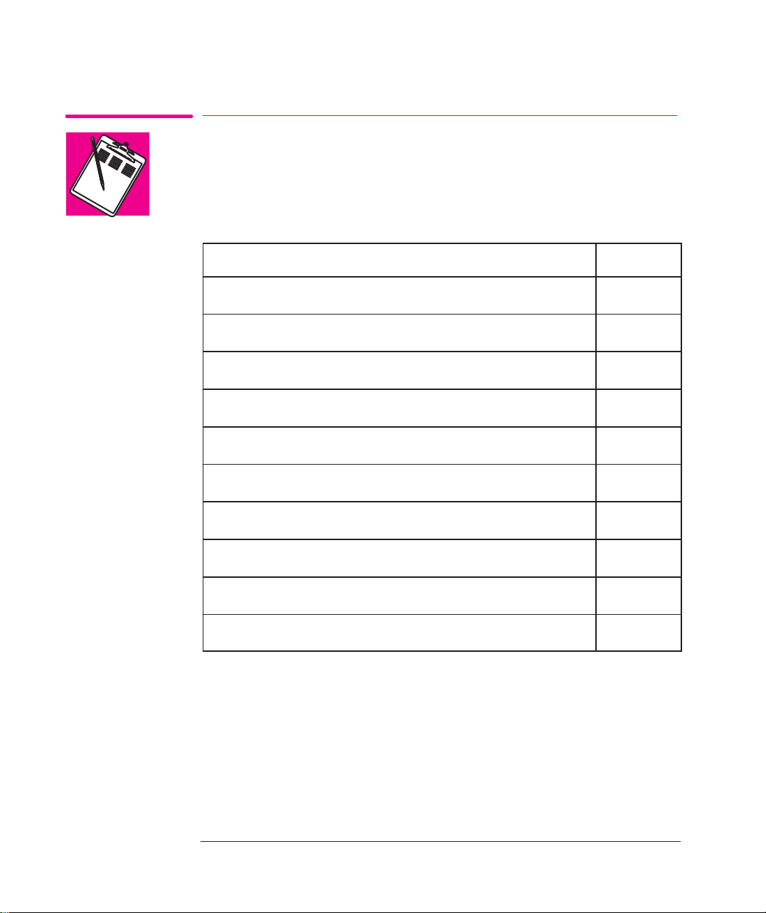
Where To Find the Most Commonly Needed Information
To find how to ... go to ...
Install the plotter
Connect the plotter
Choose media
Load media
Replace the cartridges
See the plotter’s current configuration
Clear a media jam
Solve print quality problems
Interpret a front-panel message
Order accessories
T o find any other information ...
chapter 1
page 1-27
page 3-2
page 3-10
page 3-26
pages 7-2 and 7-3
page 9-8
page 9-16
page 10-2
page 11-13
go to the index
of this manual.
at the back
On page D-1 at the back of this manual, you will find a Documentation Map,
listing useful documents to help with
Setting Up and Using the Plotter
Using Application Software
Getting Support
Programmer’s References.
iv
Page 7

Contents
Finding Information iii. . . . . . . . . . . . . . . . . . . . . . . . . . . . . . . . . . . . . . . .
Welcome xiii. . . . . . . . . . . . . . . . . . . . . . . . . . . . . . . . . . . . . . . . . . . . . . . . .
1 Setting Up the Plotter
Fast Track 1-2. . . . . . . . . . . . . . . . . . . . . . . . . . . . . . . . . . . . . . . . . . . . . . . . . . . . . .
Set Up Checklist 1-4. . . . . . . . . . . . . . . . . . . . . . . . . . . . . . . . . . . . . . . . . . . . . . . . .
T ask 1: Check that You Have All the Items Required 1-5. . . . . . . . . . . . . . . . . . . . .
T ask 2: Install Memory Expansion Modules (Optional) 1-6. . . . . . . . . . . . . . . . . . .
T ask 3: Switch On and Change the Language From English (Optionally) 1-9. . . . .
T ask 4: Load Media 1-11. . . . . . . . . . . . . . . . . . . . . . . . . . . . . . . . . . . . . . . . . . . . . .
T ask 5: Load the Print Cartridge(s) 1-20. . . . . . . . . . . . . . . . . . . . . . . . . . . . . . . . . .
T ask 6: Print a Demonstration Plot (Optional) 1-24. . . . . . . . . . . . . . . . . . . . . . . . .
T ask 7: Connect the Plotter To Your Computer 1-27. . . . . . . . . . . . . . . . . . . . . . . . .
T ask 8: Configure the Serial Interface (Serial Interface Users Only) 1-29. . . . . . . .
T ask 9: Set Up Your Software 1-35. . . . . . . . . . . . . . . . . . . . . . . . . . . . . . . . . . . . . .
T ask 10: Print a Test Plot 1-39. . . . . . . . . . . . . . . . . . . . . . . . . . . . . . . . . . . . . . . . . .
Extra Tips for UNIX Users 1-40. . . . . . . . . . . . . . . . . . . . . . . . . . . . . . . . . . . . . . . .
2 Learning How to Use the Front-Panel Display (Tutorial)
The Front Panel 2-2. . . . . . . . . . . . . . . . . . . . . . . . . . . . . . . . . . . . . . . . . . . . . . . . . .
The Display Section 2-3. . . . . . . . . . . . . . . . . . . . . . . . . . . . . . . . . . . . . . . . . . . .
Printing the Menus Plot 2-5. . . . . . . . . . . . . . . . . . . . . . . . . . . . . . . . . . . . . . . . . . . .
Description of the Menus Plot 2-5. . . . . . . . . . . . . . . . . . . . . . . . . . . . . . . . . . . .
Entering the Menu System 2-6. . . . . . . . . . . . . . . . . . . . . . . . . . . . . . . . . . . . . . . . .
Navigating the Menu System 2-7. . . . . . . . . . . . . . . . . . . . . . . . . . . . . . . . . . . . . . .
Menu Graphics Used in this Manual 2-9. . . . . . . . . . . . . . . . . . . . . . . . . . . . . . .
Other T ypes of Screens 2-10. . . . . . . . . . . . . . . . . . . . . . . . . . . . . . . . . . . . . . . . . . .
Examples 2-11. . . . . . . . . . . . . . . . . . . . . . . . . . . . . . . . . . . . . . . . . . . . . . . . . . . . . .
CONTENTS
v
Page 8

Contents
3 Working with Media and Cartridges
Choosing Media 3-2. . . . . . . . . . . . . . . . . . . . . . . . . . . . . . . . . . . . . . . . . . . . . . . . . .
Five Important Points about Media T ypes 3-2. . . . . . . . . . . . . . . . . . . . . . . . . . .
Supported Media T ypes 3-3. . . . . . . . . . . . . . . . . . . . . . . . . . . . . . . . . . . . . . . . .
Physical Characteristics of Media T ypes 3-4. . . . . . . . . . . . . . . . . . . . . . . . . . . .
Cost And Color Support of Media T ypes (DesignJet 750C Plus) 3-5. . . . . . . . .
Combinations of Media T ype and Print Quality 3-6. . . . . . . . . . . . . . . . . . . . . . .
T ypical Media Type Choices by Application 3-7. . . . . . . . . . . . . . . . . . . . . . . . .
Caring For Your Media 3-9. . . . . . . . . . . . . . . . . . . . . . . . . . . . . . . . . . . . . . . . . . . .
Loading Media 3-10. . . . . . . . . . . . . . . . . . . . . . . . . . . . . . . . . . . . . . . . . . . . . . . . . .
T o Change a Roll 3-10. . . . . . . . . . . . . . . . . . . . . . . . . . . . . . . . . . . . . . . . . . . . .
T o Load a Sheet 3-18. . . . . . . . . . . . . . . . . . . . . . . . . . . . . . . . . . . . . . . . . . . . . .
Compensating for Badly Cut Media 3-21. . . . . . . . . . . . . . . . . . . . . . . . . . . . . . .
T o Adjust Skew Tolerance 3-21. . . . . . . . . . . . . . . . . . . . . . . . . . . . . . . . . . . . . .
Unloading Media 3-22. . . . . . . . . . . . . . . . . . . . . . . . . . . . . . . . . . . . . . . . . . . . . . . .
Drying Time 3-22. . . . . . . . . . . . . . . . . . . . . . . . . . . . . . . . . . . . . . . . . . . . . . . . .
T o Adjust Drying Time 3-23. . . . . . . . . . . . . . . . . . . . . . . . . . . . . . . . . . . . . . . . .
T o Unload a Sheet After Plotting 3-24. . . . . . . . . . . . . . . . . . . . . . . . . . . . . . . . .
T o Remove an Unused Sheet 3-25. . . . . . . . . . . . . . . . . . . . . . . . . . . . . . . . . . . .
Replacing Cartridges 3-26. . . . . . . . . . . . . . . . . . . . . . . . . . . . . . . . . . . . . . . . . . . . .
When to Replace Cartridges 3-26. . . . . . . . . . . . . . . . . . . . . . . . . . . . . . . . . . . . .
Before Replacing Cartridges 3-27. . . . . . . . . . . . . . . . . . . . . . . . . . . . . . . . . . . . .
T o Replace a Cartridge 3-28. . . . . . . . . . . . . . . . . . . . . . . . . . . . . . . . . . . . . . . . .
vi
Page 9

4 Controlling the Page Format
Page Size 4-2. . . . . . . . . . . . . . . . . . . . . . . . . . . . . . . . . . . . . . . . . . . . . . . . . . . . . . .
Do You Need to Adjust the Page Size in the Front Panel? 4-3. . . . . . . . . . . . . . .
T o Adjust the Page Size from the Front Panel 4-4. . . . . . . . . . . . . . . . . . . . . . . .
Page Size and Clipped Plots 4-5. . . . . . . . . . . . . . . . . . . . . . . . . . . . . . . . . . . . . .
Page Size and Nesting (Roll Media Only) 4-5. . . . . . . . . . . . . . . . . . . . . . . . . . .
Adjusting the Margins (Roll Media Only) 4-6. . . . . . . . . . . . . . . . . . . . . . . . . . . . .
Margins and Automatic Cutting 4-6. . . . . . . . . . . . . . . . . . . . . . . . . . . . . . . . . . .
Rotating a Plot 4-7. . . . . . . . . . . . . . . . . . . . . . . . . . . . . . . . . . . . . . . . . . . . . . . . . . .
Rotating a Drawing from the Front Panel 4-7. . . . . . . . . . . . . . . . . . . . . . . . . . . .
T o Rotate a Plot from the Front Panel 4-7. . . . . . . . . . . . . . . . . . . . . . . . . . . . . .
Exactly What Is Rotated? 4-8. . . . . . . . . . . . . . . . . . . . . . . . . . . . . . . . . . . . . . . .
The Rotate Feature and Clipped Plots 4-8. . . . . . . . . . . . . . . . . . . . . . . . . . . . . .
How Does Rotate Interact with Your Software? 4-9. . . . . . . . . . . . . . . . . . . . . . .
Plotting a Mirror Image 4-10. . . . . . . . . . . . . . . . . . . . . . . . . . . . . . . . . . . . . . . . . . .
5 Controlling a Plot’s Overall Appearance
Ways To Control the Plot’s Appearance 5-2. . . . . . . . . . . . . . . . . . . . . . . . . . . . . . .
Why Change the Appearance of the Plot Using the Front Panel Rather Than
from Your Software? 5-2. . . . . . . . . . . . . . . . . . . . . . . . . . . . . . . . . . . . . . . . . . .
Changing Pen Widths and Colors/Shades Using the Plotter’s Internal Palettes 5-3.
T o See the Current Palette Settings 5-3. . . . . . . . . . . . . . . . . . . . . . . . . . . . . . . .
T o See the Colors Available For a Palette (DesignJet 750C Plus) 5-4. . . . . . . . .
T o Change the Palette Settings 5-5. . . . . . . . . . . . . . . . . . . . . . . . . . . . . . . . . . . .
T o Change the Selection of the Current Palette 5-6. . . . . . . . . . . . . . . . . . . . . . .
Changing the Treatment of Overlapping Lines (Merge Feature) 5-7. . . . . . . . . . . .
Changing the Overall Lightness/Darkness of a Plot 5-8. . . . . . . . . . . . . . . . . . . . . .
Printing Color Drawings in Monochrome 5-9. . . . . . . . . . . . . . . . . . . . . . . . . . . . . .
T o Switch between Color and Monochrome 5-10. . . . . . . . . . . . . . . . . . . . . . . .
Choosing an Appropriate Print Quality 5-11. . . . . . . . . . . . . . . . . . . . . . . . . . . . . . .
T o Change the Print Quality 5-13. . . . . . . . . . . . . . . . . . . . . . . . . . . . . . . . . . . . .
Improving Line Quality and Graphics Detail (DesignJet 750C Plus) 5-14. . . . .
Contents
CONTENTS
vii
Page 10

Contents
6 Managing Your Plots
Managing Plots Currently Being Printed or Drying 6-2. . . . . . . . . . . . . . . . . . . . . .
T o Cancel a Plot 6-2. . . . . . . . . . . . . . . . . . . . . . . . . . . . . . . . . . . . . . . . . . . . . . .
T o Cut a Plot Before Drying Is Complete (Roll Media Only) 6-2. . . . . . . . . . . .
T o Pause while Printing a Series of Plots 6-3. . . . . . . . . . . . . . . . . . . . . . . . . . . .
Managing Plots Not Yet Printed (The Queue) 6-4. . . . . . . . . . . . . . . . . . . . . . . . . . .
T o Start Printing a Plot That Is Waiting for a Timeout 6-4. . . . . . . . . . . . . . . . . .
What Is the Queue? 6-5. . . . . . . . . . . . . . . . . . . . . . . . . . . . . . . . . . . . . . . . . . . . .
T o Identify a Page in the Queue 6-6. . . . . . . . . . . . . . . . . . . . . . . . . . . . . . . . . . .
T o See the Size of a Page in the Queue 6-7. . . . . . . . . . . . . . . . . . . . . . . . . . . . .
T o Prioritize a Page in the Queue 6-7. . . . . . . . . . . . . . . . . . . . . . . . . . . . . . . . . .
T o Delete a Page from the Queue 6-7. . . . . . . . . . . . . . . . . . . . . . . . . . . . . . . . . .
T o Make Copies of a Page in the Queue 6-8. . . . . . . . . . . . . . . . . . . . . . . . . . . . .
T o Replot an Image Using the Plotter’s Memory (DesignJet 700) 6-9. . . . . . . . . . .
Avoiding Media Waste by Nesting Pages (Roll Media Only) 6-10. . . . . . . . . . . . . .
What Is Nesting? 6-10. . . . . . . . . . . . . . . . . . . . . . . . . . . . . . . . . . . . . . . . . . . . . .
When Does the Plotter Try to Nest Pages? 6-11. . . . . . . . . . . . . . . . . . . . . . . . . .
Which Pages Qualify for Nesting? 6-11. . . . . . . . . . . . . . . . . . . . . . . . . . . . . . . .
Which Pages May be Rotated? 6-1 1. . . . . . . . . . . . . . . . . . . . . . . . . . . . . . . . . . .
T o Turn Nesting On or Off and Choose the Nesting Method 6-12. . . . . . . . . . . .
What Happens to Nesting if You Turn Queueing Off? 6-12. . . . . . . . . . . . . . . . .
How Long Does the Plotter Wait for Another File? 6-12. . . . . . . . . . . . . . . . . . .
Getting the Best From Nesting (Nesting and Margins) 6-13. . . . . . . . . . . . . . . .
Nesting and the Rotate Feature 6-13. . . . . . . . . . . . . . . . . . . . . . . . . . . . . . . . . . .
viii
Page 11

7 Reconfiguring the Plotter
T o See the Current Overall Configuration of the Plotter 7-2. . . . . . . . . . . . . . . . . . .
T o See the Current Configuration of the Front-Panel Settings 7-3. . . . . . . . . . . . . .
T o Change the Front-Panel Settings 7-4. . . . . . . . . . . . . . . . . . . . . . . . . . . . . . . . . .
Recalibrating the Plotter for Accuracy 7-5. . . . . . . . . . . . . . . . . . . . . . . . . . . . . . . .
When to Recalibrate the Plotter 7-5. . . . . . . . . . . . . . . . . . . . . . . . . . . . . . . . . . .
A Quick Guide to Whether Recalibration Is Necessary 7-5. . . . . . . . . . . . . . . . .
T o Recalibrate the Plotter 7-6. . . . . . . . . . . . . . . . . . . . . . . . . . . . . . . . . . . . . . . .
T o Restore the Factory’s Calibration 7-6. . . . . . . . . . . . . . . . . . . . . . . . . . . . . . .
Changing the Graphics Language Setting for a Different Application 7-7. . . . . . . .
T o Change the Graphics Language Setting 7-7. . . . . . . . . . . . . . . . . . . . . . . . . .
Graphics Language and Networks 7-8. . . . . . . . . . . . . . . . . . . . . . . . . . . . . . . . .
Changing the Serial Interface Settings 7-9. . . . . . . . . . . . . . . . . . . . . . . . . . . . . . . .
T o Change the Serial-Interface Settings 7-9. . . . . . . . . . . . . . . . . . . . . . . . . . . . .
Change the I/O Timeout Setting 7-9. . . . . . . . . . . . . . . . . . . . . . . . . . . . . . . . . . . . .
T o Upgrade Your Plotter with More Memory 7-10. . . . . . . . . . . . . . . . . . . . . . . . . .
File Size and Memory Usage 7-10. . . . . . . . . . . . . . . . . . . . . . . . . . . . . . . . . . . .
T o Upgrade Your Plotter with the Postscript Option 7-11. . . . . . . . . . . . . . . . . . . . .
T o Upgrade Your Plotter with a Network Interface 7-12. . . . . . . . . . . . . . . . . . . . . .
HP JetDirect Print Server 7-12. . . . . . . . . . . . . . . . . . . . . . . . . . . . . . . . . . . . . . .
Contents
CONTENTS
8 Maintaining the Plotter
Replacing the Print Cartridge(s) 8-2. . . . . . . . . . . . . . . . . . . . . . . . . . . . . . . . . . . . .
Cleaning the Plotter 8-2. . . . . . . . . . . . . . . . . . . . . . . . . . . . . . . . . . . . . . . . . . . . . . .
“Normal” Plotter Use 8-3. . . . . . . . . . . . . . . . . . . . . . . . . . . . . . . . . . . . . . . . . . . . .
T o Print the Service Configuration Plot 8-4. . . . . . . . . . . . . . . . . . . . . . . . . . . . .
ix
Page 12

Contents
9 Troubleshooting
Using the Documentation to Help Solve Problems 9-2. . . . . . . . . . . . . . . . . . . . . . .
Locating the Source of the Problem 9-3. . . . . . . . . . . . . . . . . . . . . . . . . . . . . . . . . .
Solving Media-Handling Problems 9-4. . . . . . . . . . . . . . . . . . . . . . . . . . . . . . . . . . .
If the Front Panel Keeps T elling you Media Is Misaligned orIncorrectly
positioned. 9-4. . . . . . . . . . . . . . . . . . . . . . . . . . . . . . . . . . . . . . . . . . . . . . . . . . . .
If Media Crumples when you Load It 9-5. . . . . . . . . . . . . . . . . . . . . . . . . . . . . . .
If Plots Do Not Feed Out Properly From the Plotter 9-5. . . . . . . . . . . . . . . . . . .
If The Automatic Cutter Does Not Cut Immediately When a Plot Has
ąFinished 9-5. . . . . . . . . . . . . . . . . . . . . . . . . . . . . . . . . . . . . . . . . . . . . . . . . . . .
If The Automatic Cutter Does Not Work 9-6. . . . . . . . . . . . . . . . . . . . . . . . . . . .
If Plots Fall On the Floor After Being Cut 9-6. . . . . . . . . . . . . . . . . . . . . . . . . . .
If a Sheet Is Ejected When You Switch On the Plotter 9-6. . . . . . . . . . . . . . . . .
If Plots Do Not Stack Properly In the Bin 9-6. . . . . . . . . . . . . . . . . . . . . . . . . . .
Solving Print Cartridge Problems 9-7. . . . . . . . . . . . . . . . . . . . . . . . . . . . . . . . . . . .
If the Access Cartridge(s) Key Does Not Work 9-7. . . . . . . . . . . . . . . . . . . . . . .
If the Plotter Runs the Cartridge-alignment Routine Unexpectedly 9-7. . . . . . . .
If Brand New Cartridge(s) Have Problems 9-7. . . . . . . . . . . . . . . . . . . . . . . . . .
Clearing a Media Jam 9-8. . . . . . . . . . . . . . . . . . . . . . . . . . . . . . . . . . . . . . . . . . . . .
Solving Communication Problems 9-9. . . . . . . . . . . . . . . . . . . . . . . . . . . . . . . . . . .
If There is a Problem Communicating between Your Computer
and the Plotter 9-9. . . . . . . . . . . . . . . . . . . . . . . . . . . . . . . . . . . . . . . . . . . . . . . . .
Solving Problems with Plot Position or Content 9-10. . . . . . . . . . . . . . . . . . . . . . . .
If the Plot Is Completely Blank 9-10. . . . . . . . . . . . . . . . . . . . . . . . . . . . . . . . . .
If the Output Contains Only a Partial Plot 9-11. . . . . . . . . . . . . . . . . . . . . . . . . .
If the Plot Is Clipped 9-12. . . . . . . . . . . . . . . . . . . . . . . . . . . . . . . . . . . . . . . . . . .
If a Long-axis Plot Is Clipped 9-12. . . . . . . . . . . . . . . . . . . . . . . . . . . . . . . . . . . .
If the Entire Plot Is in One Quadrant of the Correct Plotting Area 9-13. . . . . . .
If the Plot Is Unexpectedly Rotated 9-13. . . . . . . . . . . . . . . . . . . . . . . . . . . . . . .
If the Plot Is a Mirror Image of Your Drawing 9-13. . . . . . . . . . . . . . . . . . . . . . .
If the Plot Is Inaccurate 9-13. . . . . . . . . . . . . . . . . . . . . . . . . . . . . . . . . . . . . . . . .
If the Plot Is Distorted or Unintelligible 9-14. . . . . . . . . . . . . . . . . . . . . . . . . . . .
If One Plot Overlays Another Plot On the Same Sheet 9-14. . . . . . . . . . . . . . . .
If Pen Settings Seem to Have No Effect 9-14. . . . . . . . . . . . . . . . . . . . . . . . . . . .
x
Page 13

Contents
If the Plotter Produces a Black and White Plot When You Expected a Color
ąPlot (DesignJet 750C Plus) 9-14. . . . . . . . . . . . . . . . . . . . . . . . . . . . . . . . . . . .
If the Plotter Has Printed a Different Plot Than the One You Were
ąExpecting 9-15. . . . . . . . . . . . . . . . . . . . . . . . . . . . . . . . . . . . . . . . . . . . . . . . .
If the Quality Of a Color Plot Is Not as Good as You W ere Expecting
(DesignJet 750C Plus) 9-15. . . . . . . . . . . . . . . . . . . . . . . . . . . . . . . . . . . . . . .
Solving Print Quality Problems 9-16. . . . . . . . . . . . . . . . . . . . . . . . . . . . . . . . . . . . .
If the Color Is Not as Expected 9-16. . . . . . . . . . . . . . . . . . . . . . . . . . . . . . . . . . .
If there are White Streaks in Solid Fill Areas 9-16. . . . . . . . . . . . . . . . . . . . . . . .
If there are Other Gaps in Solid Areas or in Lines (DesignJet 750C Plus) 9-17.
If there are Jagged Vertical or Horizontal Lines 9-18. . . . . . . . . . . . . . . . . . . . . .
If there are Slightly Warped Lines 9-18. . . . . . . . . . . . . . . . . . . . . . . . . . . . . . . .
If there are Color “Shadows” (DesignJet 750C Plus) 9-18. . . . . . . . . . . . . . . . . .
If One or More Cartridges are not Printing at All 9-18. . . . . . . . . . . . . . . . . . . .
If there are Blurred Lines (Ink “Bleeds” from Lines) 9-19. . . . . . . . . . . . . . . . . .
If there are Blotchy Areas (Uneven Fill Density) 9-19. . . . . . . . . . . . . . . . . . . . .
If the Plot Is T oo Dark or the Color Too Saturated 9-19. . . . . . . . . . . . . . . . . . . .
If there Is Pronounced Banding In Area Fills 9-20. . . . . . . . . . . . . . . . . . . . . . . .
If Ink Smears After You Remove a Plot 9-20. . . . . . . . . . . . . . . . . . . . . . . . . . . .
Solving Front Panel Problems 9-21. . . . . . . . . . . . . . . . . . . . . . . . . . . . . . . . . . . . . .
If the Access Cartridges Key Does Not Work 9-21. . . . . . . . . . . . . . . . . . . . . . .
If None of the Front Panel Keys Work 9-21. . . . . . . . . . . . . . . . . . . . . . . . . . . . .
If Page Format/Rotate Does Not Work 9-21. . . . . . . . . . . . . . . . . . . . . . . . . . . . .
If A Display Message Will Not Clear 9-21. . . . . . . . . . . . . . . . . . . . . . . . . . . . . .
If A “System Error” Message Is Displayed 9-22. . . . . . . . . . . . . . . . . . . . . . . . .
If An “Out Of Memory/Data Was Lost” Message Is Displayed 9-22. . . . . . . . . .
Solving Miscellaneous Problems 9-23. . . . . . . . . . . . . . . . . . . . . . . . . . . . . . . . . . .
If the Plotter Does Not Plot 9-23. . . . . . . . . . . . . . . . . . . . . . . . . . . . . . . . . . . . .
If the Plotter Seems T oo Slow 9-23. . . . . . . . . . . . . . . . . . . . . . . . . . . . . . . . . . .
If the Plotter Waits Too Long to Plot a Nest 9-24. . . . . . . . . . . . . . . . . . . . . . . . .
If the Plotter Performs the Cartridge Alignment Routine Unexpectedly 9-24. . .
If the Bail (Black Metal Bar) Does Not Lower All the Way 9-24. . . . . . . . . . . .
Getting Help 9-25. . . . . . . . . . . . . . . . . . . . . . . . . . . . . . . . . . . . . . . . . . . . . . . . . . .
What to Do Before You Call 9-25. . . . . . . . . . . . . . . . . . . . . . . . . . . . . . . . . . . . .
If a Repair Is Needed 9-25. . . . . . . . . . . . . . . . . . . . . . . . . . . . . . . . . . . . . . . . . .
CONTENTS
xi
Page 14

Contents
10 Front-Panel Messages
Front Panel Messages 10-2. . . . . . . . . . . . . . . . . . . . . . . . . . . . . . . . . . . . . . . . . . . .
11 Reference
Plotter Specifications 11-2. . . . . . . . . . . . . . . . . . . . . . . . . . . . . . . . . . . . . . . . . . . . .
Interface Specifications 11-7. . . . . . . . . . . . . . . . . . . . . . . . . . . . . . . . . . . . . . . . . . .
Interface Cables 11-8. . . . . . . . . . . . . . . . . . . . . . . . . . . . . . . . . . . . . . . . . . . . . . . . .
Regulatory Notices 11-10. . . . . . . . . . . . . . . . . . . . . . . . . . . . . . . . . . . . . . . . . . . . .
T o Obtain a Material Safety Data Sheet (MSDS) 11-10. . . . . . . . . . . . . . . . . . . .
Electromagnetic Compatibility (EMC) 11-10. . . . . . . . . . . . . . . . . . . . . . . . . . . .
T elecommunications Statement 11-11. . . . . . . . . . . . . . . . . . . . . . . . . . . . . . . . .
Declaration of Conformity 11-12. . . . . . . . . . . . . . . . . . . . . . . . . . . . . . . . . . . . .
Ordering Accessories 11-13. . . . . . . . . . . . . . . . . . . . . . . . . . . . . . . . . . . . . . . . . . . .
HP-GL/2 and HP RTL Programming Information 11-16. . . . . . . . . . . . . . . . . . .
How to Order Supplies and Accessories 11-16. . . . . . . . . . . . . . . . . . . . . . . . . .
12 Glossary
Index
Documentation Map
Please Give Us Your Feedback (Removable)
xii
Page 15
Welcome
e
Welcom
700
An Introduction To Your Plotter’s Main Features
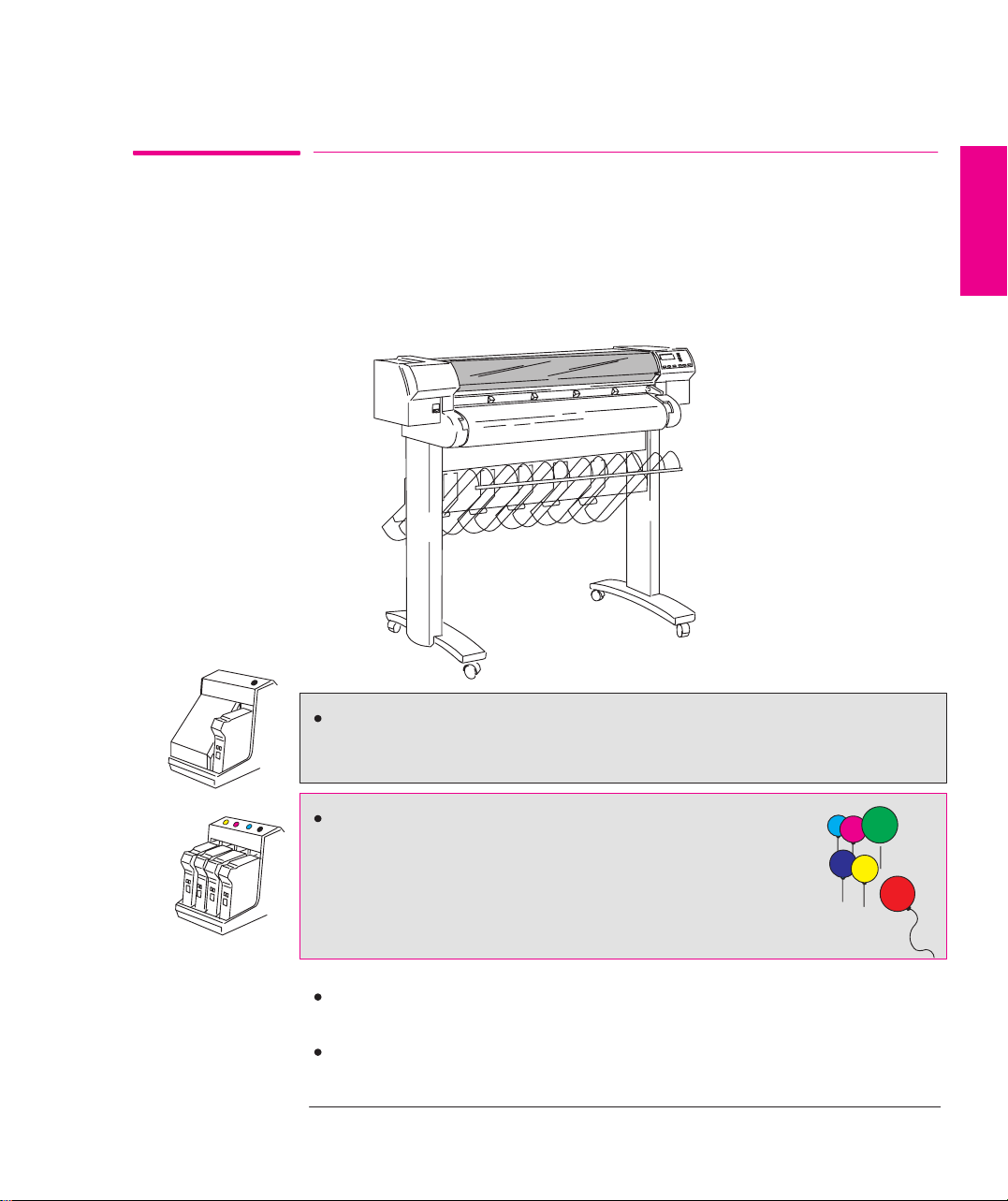
The HP DesignJet 700 and HP DesignJet 750C Plus are large-format inkjet plotters
that use HP
The HP DesignJet 700 will print only in black. It uses a single cartridge,
containing black ink, two of which are supplied with your plotter.
disposable print cartridge technology.
WELCOME
750C Plus
The HP DesignJet 750C Plus will print in color or black. Your
plotter uses a set of four disposable print cartridges: yellow,
cyan, magenta and black. a set is supplied with your plotter (a
spare black cartridge is also included). From time to time, you
will need to replace them. All other supported colors are
generated using these four cartridges up to a total of over 16
million different colors for all your needs.
Product C4705A is the DesignJet 700 and Product C4708A is the DesignJet
750C Plus. Both Plotters are the D/A1-size model.
Product C4706A is the DesignJet 700 and Product C4709A is the DesignJet
750C Plus. Both Plotters are the E/A0-size model.
xiii
Page 16
Welcome
Print Quality
In monochrome, the print resolution can be set to either true 300 or true 600 dots
per inch (dpi). In color, the print resolution can be set to true 300 or addressable
600 dpi. You can choose between three levels of print quality either from your
software or from the plotter’s front panel. These are:
Best
Normal
Fast.
Media
You can plot on rolls or sheets up to E/A0 size or D/A1 size, depending on the
plotter model you have bought.
A large variety of media types are supported:
700
750C Plus
750C Plus
Opaque bond (one roll is supplied with your plotter)
Translucent bond
Natural tracing paper
Vellum
Coated paper (one roll is supplied with your plotter)
Heavy coated paper
Matte and clear film.
In addition for the HP DesignJet 750C Plus:
High-gloss and semi-gloss photo paper
High-gloss film.
xiv
Page 17
xxxxxxx
e
yyyyy
Welcom
User Interface
The plotter’s front panel includes an easy-to-use interface with a two-line display,
giving you access to a comprehensive set of plotter functions and to a number of
useful sample plots.
WELCOME
Queueing & Nesting
Queue mgmt
Page ID
This manual includes a short tutorial to teach you how to navigate around the
menus. Wherever a front-panel feature is explained in this manual, a simple
graphic shows you how to access that feature from the front-panel menus.
Software Applications and Drivers
T o make sure that your plotter prints exactly what you were expecting – in terms of
size, position, orientation, color and quality – the key is to use the correct driver for
the combination of your application software and your plotter, and to be confident
that it is configured correctly.
T wo types of HP drivers are supplied with your plotter:
One or more for AutoCAD users,
One for users of MicrosoftR Windows applications.
These drivers come with printed and on line documentation to help you install and
configure them correctly.
Generally , software applications include their own drivers too. With this plotter we
have provided free of charge a set of Software Application Notes for the most
popular applications. If you find your own application in these notes, we
recommend that you use the information they contain as an overall guide to
configuring the software for your plotter.
xv
Page 18
700
750C Plus
Welcome
Memory and Upgrades
Your plotter comes with a standard memory of 5.5 MB (4 MB of main memory
and 1.5 MB of printing memory). In case you need to print particularly large
1
, you can upgrade your plotter with up to two 32 MB memory expansion
files
modules, taking the maximum memory up to 69.5 MB (5.5 + (2 x 32)).
Your plotter comes with a standard memory of 11 MB (8 MB of main memory and
3 MB of printing memory). In case you need to print particularly large files
can upgrade your plotter with up to two 32 MB memory expansion modules,
taking the maximum memory up to 75 MB (11 + (2 x 32)).
Other upgrades available are:
A PostScriptr upgrade kit (including a ROM SIMM for the plotter and an
Adobe PostScript driver for your software).
A network interface card (the HP JetDirect Print Server).
1
, you
1
Note that there is not a one-for-one relationship between the plotter’s memory and the maximum size
of file that it can plot.
xvi
Page 19
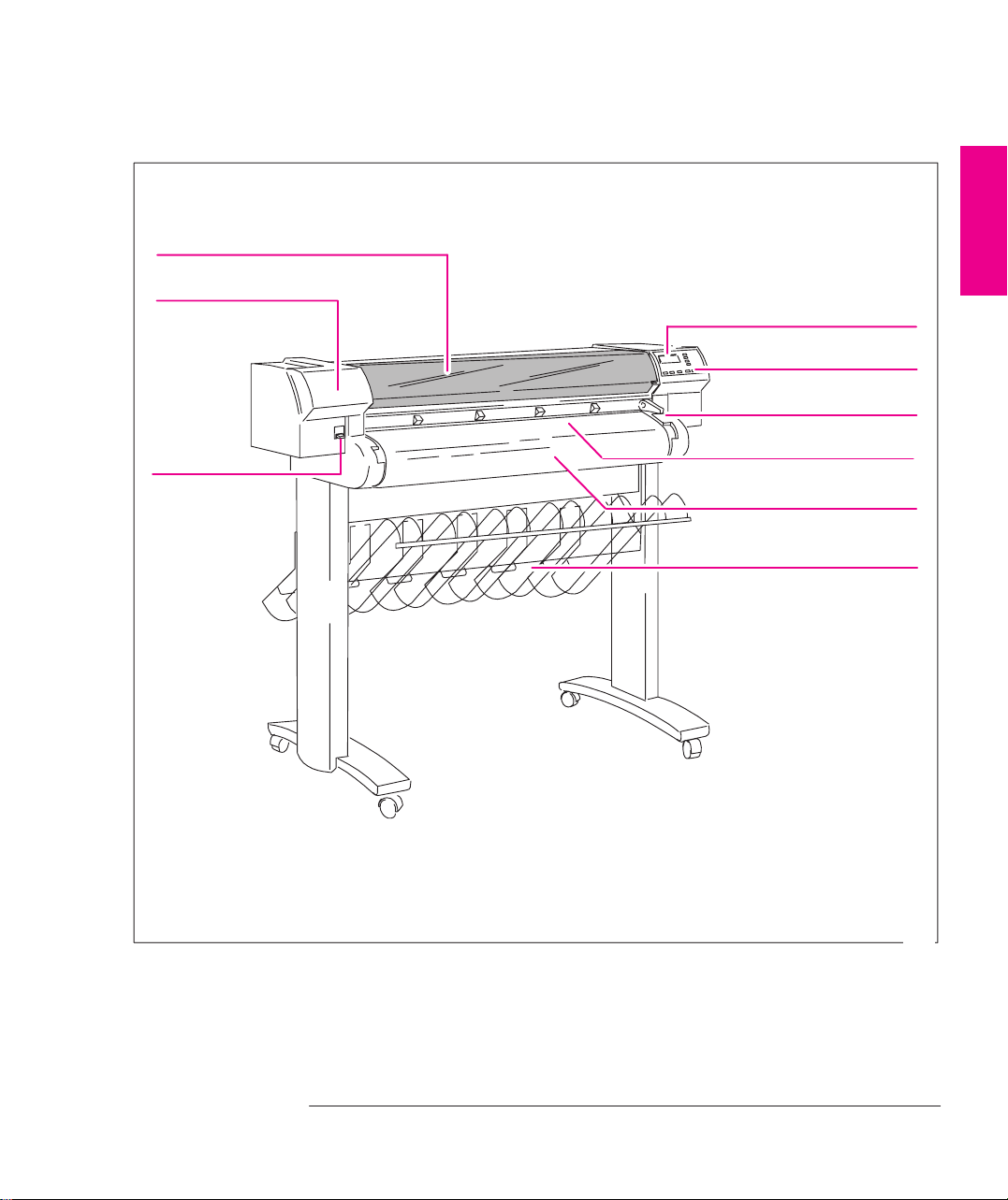
Front View
e
Welcom
Window
Print Cartridge(s)
(Inside)
ON/OFF Switch
WELCOME
Front Panel Display
Front Panel
Media Lever
Media-Entry Slot
Roll Cover
Media Bin
1835
xvii
Page 20
Welcome
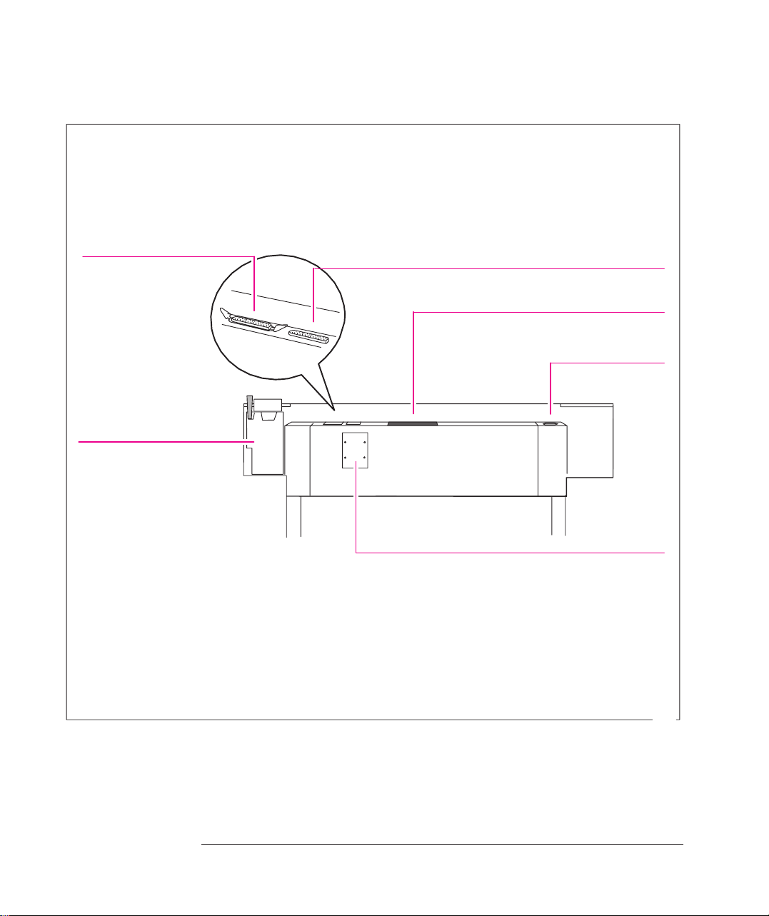
Rear View
Parallel-Interface
Pocket For
Quick Reference Guide
And Media Knife
Serial-Interface
Slot For Optional Network Interface
Socket For
Power Cord
Slots For Memory Expansion
Modules and Upgrades
(Behind Cover Plate)
xviii
1844
Page 21

1
Fast Track 1-2. . . . . . . . . . . . . . . . . . . . . . . . . . . . . . . . . . . . . . . . .
Set Up Checklist 1-4. . . . . . . . . . . . . . . . . . . . . . . . . . . . . . . . . . . . .
Task 1: Check That You Have All the Items Required 1-5. . . . . .
Task 2: Install Memory Expansion Modules (Optional) 1-6. . . .
Task 3: Switch On and
Change the Language From English (Optional) 1-9. . . .
Task 4: Load Media 1-11. . . . . . . . . . . . . . . . . . . . . . . . . . . . . . .
Task 5: Load the Print Cartridge(s) 1-20. . . . . . . . . . . . . . . . . . .
Task 6: Print a Demonstration Plot (Optional) 1-24. . . . . . . . . . .
Task 7: Connect the Plotter to Your Computer 1-27. . . . . . . . . . .
Task 8: Configure the Interface (Serial interface users only) 1-29
Task 9: Set Up Your Software 1-35. . . . . . . . . . . . . . . . . . . . . . .
Task 10: Print a Test Plot 1-39. . . . . . . . . . . . . . . . . . . . . . . . . . . .
Extra Tips For UNIX Users 1-40. . . . . . . . . . . . . . . . . . . . . . . . . . .
Setting Up Your Plotter
SETUP
1
Installation, Connection,
and Configuration
1-1
Page 22
Setting Up the Plotter
Fast Track
Fast Track
If You Meet All the Following Requirements:
You want English as the language of the front-panel display and of the plotter’s
internal plots.
You are experienced at installing printers or plotters.
You don’t want to add extra memory .
700
750C Plus
700
For the HP DesignJet 700:
You are going to use roll media.
For the HP DesignJet 750C Plus:
You are going to use roll media and print in color.
You know whether to connect the plotter directly to your computer or to a
network and whether to use the parallel or serial interface, and you already have
the right cable.
(Serial interface users) Your computer’s RS-232-C settings are 9600 baud, no
parity, 8 data bits and 1 stop bit.
... Just Do the Following Six Steps and Skip the Rest of This Chapter.
1 Connect the power cord and switch on.
2 Load the roll of media supplied, following the instructions on the label inside
the plotter’s roll cover. Watch the front-panel display for further instructions.
3 Press
Access Cartridge(s) and open the plotter window.
For the HP DesignJet 700:
Load the black print-cartridge into the carriage on the left side of the plotter.
Don’t forget to remove the tape from the cartridge.
750C Plus
For the HP DesignJet 750C Plus:
Load the four color print-cartridges into the carriage on the left side of the
plotter. Don’t forget to remove the tape from the cartridges.
Continued...
1-2
Page 23

Setting Up the Plotter
Fast Track
4 Close the plotter’s window and let the plotter run its automatic
cartridge-alignment procedure.
5 Switch off the plotter and your computer, connect the interface cable, and
then switch them on again.
6 Choose your driver disk(s), read the instructions on the label, and follow
any printed instructions accompanying the disks. For AutoCAD or
Microsoft Windows applications, the driver is shipped with the plotter.
For other applications, see page 1-38 for advice, and, if necessary, contact
your software vendor.
SETUP
1
1-3
Page 24
Setting Up the Plotter
Set Up Checklist
Set Up Checklist
You should already have unpacked and assembled the plotter, following the
Assembly Instructions in the box. Now you can set up the plotter, using the
checklist below as you complete each task explained in this chapter.
T ask
Check that you have all the items required.
1
Install memory expansion modules (Optional).
2
Switch on and change the language from English (Optional).
3
Load media.
4
Load the print-cartridge(s).
5
Print the demonstration plot (Optional).
6
Connect the plotter to your computer.
7
Configure the interface (Serial interface users only).
8
Set up your software.
9
Print a test plot.
10
Done? ()
1-4
Page 25
Setting Up the Plotter
T ask 1: Check That You Have All the Items Required
Task 1: Check That You Have All the Items Required
Supplied
700
750C Plus
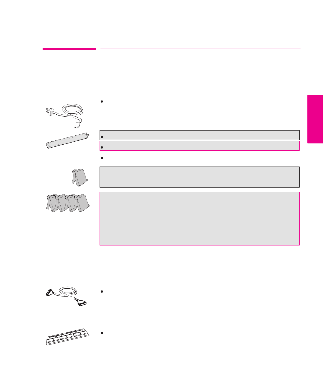
1 You need the following items, which were supplied with the plotter.
Power cord
The power cord supplied with your plotter should meet the plug requirements for
your area. However, different power cords (international options) are available. If
necessary, contact your dealer or HP Sales and Support Office.
A roll of HP Opaque Bond Paper (for the HP DesignJet 700)
A roll of HP Coated Paper (for the HP DesignJet 750C Plus)
Print cartridge(s):
For the HP DesignJet 700:
– Two black
For the HP DesignJet 750C Plus:
– One yellow
– One cyan
– One magenta
– Two black
2 Inspect the plotter itself and the above accessories. If you received any item in a
damaged condition, notify the dealer or HP Sales and Support Office where you
purchased the plotter, and file a claim with the carrier.
SETUP
1
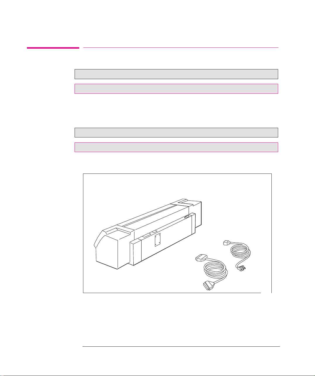
Not supplied
Optional
3 You will also need the following items, which were not supplied with the plotter.
Interface cable
For details of suitable cables, see page 11-8.
4 If you have purchased extra memory, you will need your
Memory expansion module
For details of the memory expansion modules available, see page 11-14.
1-5
Page 26
Setting Up the Plotter
T ask 2: (Optional) Install Memory Expansion Modules
Task 2: Install Memory Expansion Modules (Optional)
700
750C Plus
700
750C Plus
Your plotter comes with 5.5 MB of standard memory.
Your plotter comes with 11 MB of standard memory.
You can expand this by adding one or two memory expansion modules, in any
combination. Supported sizes are 4 MB, 8 MB, 16 MB and 32 MB. So the
maximum standard memory for your plotter is:
5.5 + 32 + 32 = 69.5 MB
11 + 32 + 32 = 75 MB
For HP part numbers, see page 11-14.
1
Make sure that the plotter is switched OFF and that neither the power cord
nor an interface cable is connected.
X
1-6
X
1847
Page 27
Setting Up The Plotter
T ask 2: (Optional) Install Memory Expansion Modules
2
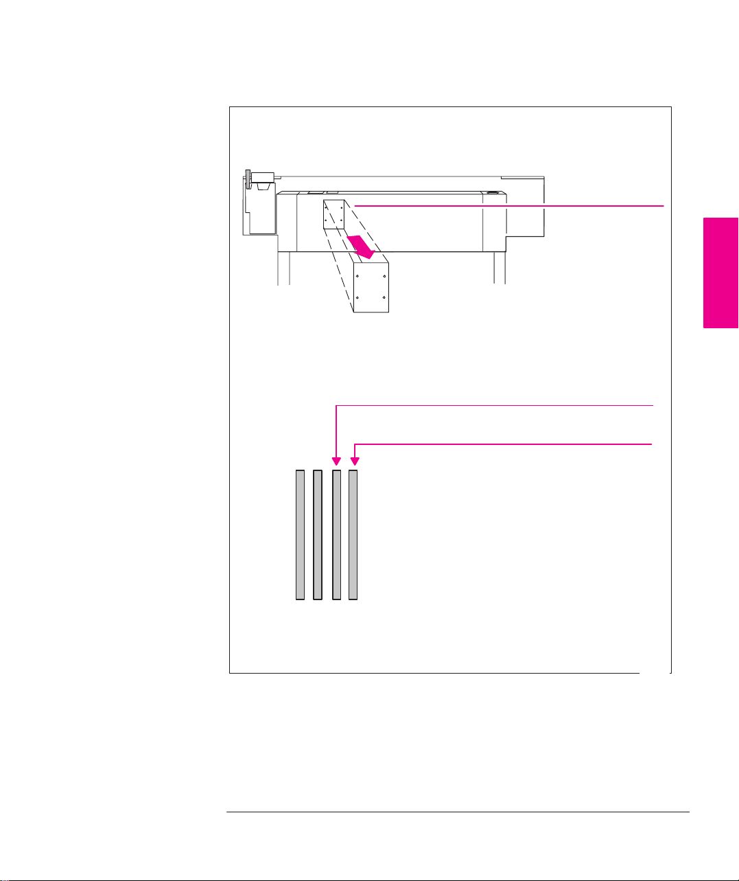
Using a flat-blade screwdriver, unscrew the cover plate at the back of the
plotter, and remove it. Unscrew only the four screws on the cover plate.
The two slots on the right are for memory expansion modules. Use slot 3
first, and then slot 4.
Slot for first memory module installed
Cover plate
SETUP
1
Slot for second memory module installed
1234
If your plotter has only one memory module, it must be in slot number 3.
1845a
1-7
Page 28
Setting Up the Plotter
T ask 2: (Optional) Install Memory Expansion Module
CAUTION
Before handling a memory module, either put on a grounding wrist strap and
attach the end to the metal chassis of the plotter, or touch the outer metal
surface of the plotter with your hand. Otherwise, static electricity from your
body could damage the memory module.
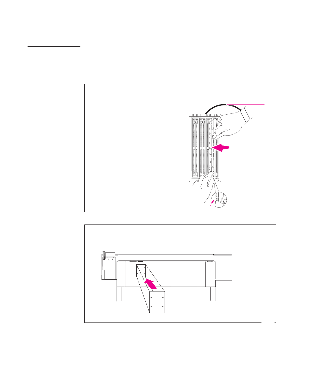
3 Take the memory module out of its bag, holding the module only by the edges.
4
a Hold the module by its
edges with the
Grounding
Wrist Strap
nonmetallic edge toward
you and the small notch
at the bottom.
b With the nonmetallic
edge angled to the right,
firmly push the module
into the slot. Gradually
straighten the angle and
push it in until it clicks
into place.
1846
5
Using a flat-blade screwdriver, replace the cover plate and its four screws.
1-8
1845b
Page 29
Setting Up the Plotter
T ask 3: Switch On and (Optional) Change the Language From English
Task 3: Switch On and Change the Language From
English (Optional)
WARNING
If English OK
or if you have
already
changed the
language
The plotter’s front-panel menus and all the plotter’s sample plots are available in
1
the following languages
: English, French, German, Italian, Japanese, Portuguese,
and Spanish. By default, the language is English.
Be sure that the power cord supplied with your plotter matches your ac power
connection requirements. Use only three-wire (earth-grounded) power cords
with this plotter.
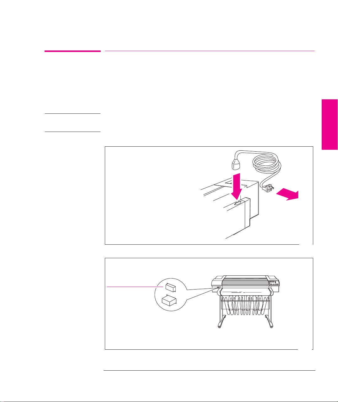
1 Make sure that the power switch on the front of the plotter is OFF.
2
Plug the power cord into the socket at
the back of the plotter, and then into
your power outlet.
3
Switch on the plotter by pushing the power switch. Then go to Step 4.
on
SETUP
1
1848
If there is no sound, nor any light on the front panel, you have a power problem.
1
The physical front-panel overlay is also available in Chinese, Korean and Taiwanese.
1843
1-9
Page 30
Setting Up the Plotter
Setup Task 3: Switch On and (Optional) Change the language From English
If English not OK
or if you want
to change the
language
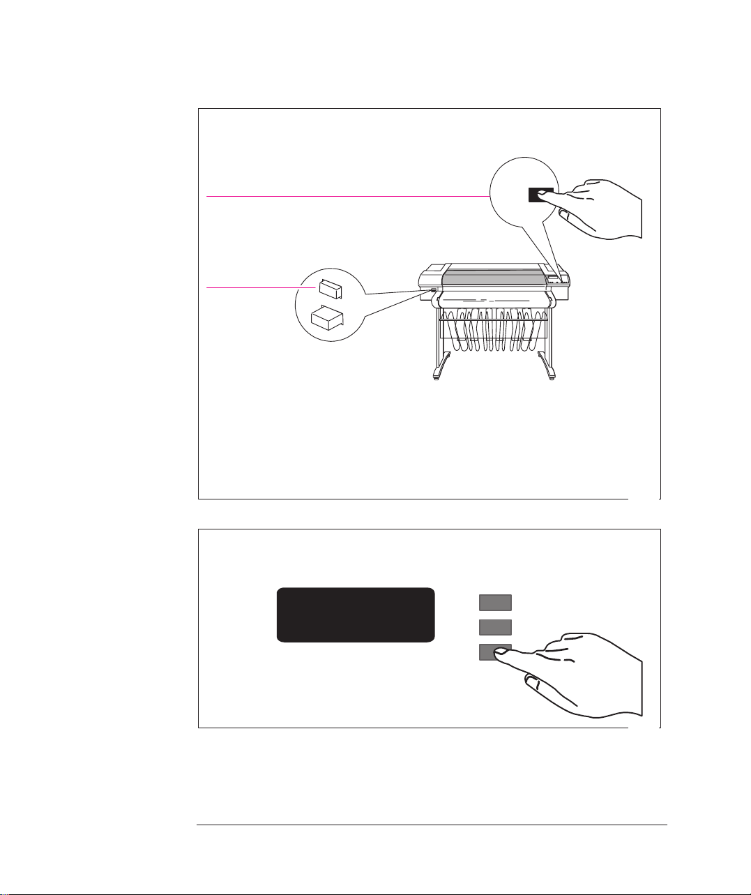
4
Hold down the Enter key on the front panel and then switch on the plotter by
pushing the power switch.
1 Press and hold
2 Switch on
Release the
Enter key when “STATUS / Initializing” appears on the front-panel
Enter
screen. If there is no sound, nor any light on the front panel, you have a power
problem.
1843a
5
When the word “English” appears on the front-panel screen, press the ↑ or
↓ key until your language appears. Then press
LANGUAGE
English
Enter.
↑
↓
Enter
1-10
0014
Page 31

Setting Up the Plotter
T ask 4: Load Media
Task 4: Load Media
For advice on the availability and use of different media types, see the section
starting on page 3-2.
IMPORTANT Because the next task is to load the cartridge(s) and carry out the automatic
cartridge alignment procedure, you must load opaque media at this stage – for
example, opaque bond (plotter paper) for the DesignJet 700 or coated paper for the
DesignJet 750C Plus, as this necessary for the alignment procedure. A roll of
suitable HP Media is supplied with your plotter.
T o load roll media, start with step 1 below.
T o load sheet media, go to page 1-18.
To Load a Roll
1 Make sure the plotter wheels are locked (the brake levers pressed down) to prevent
the plotter from moving.
SETUP
1
2
Open the roll cover and remove the empty spindle by pulling firmly on each
end. The two ends are different: end A has a media stop and end B a smaller
end cap, as shown on the next page.
B
Roll cover
Place the spindle vertically on the floor, with the media stop at the bottom,
ready for the new roll.
A
1865
1-11
Page 32

Setting Up the Plotter
T ask 4: Load Media
3
Remove the new roll from its wrapping. Remove the end cap from the top
of the spindle, and slide the new roll onto the spindle. The leading edge of
the media must wind clockwise.
End cap removed.
If the media stop falls off, push it back
in until it snaps into position.
4
Push the end cap back in, making sure that the tabs are flush against the ends of
A
the roll. Push it far enough to be firm, but do not use excessive force as this
may break the tabs.
B
0015
0016
1-12
Page 33

5
Insert the spindle so that the large media stop (A) is to the right and the
small end cap (B) to the left. Push in firmly on both ends. Be sure the
media remains flush against the media stop.
B
A
Setting Up the Plotter
T ask 4: Load Media
SETUP
1
A
Media path
The relationship of the media to the roller must be as shown in the
diagram above.
6 Check the leading edge as it unwinds from the spool. If it is uneven, trim it as
explained in step 7. Otherwise go to step 8.
0017
1837
1-13
Page 34

Setting Up the Plotter
T ask 4: Load Media
WARNING
The media cutting knife used in the next step is sharp. Make sure the plotter’s
wheels are locked. Keep fingers clear of the cutting path. Keep media cutting
knife away from children.
7
Trim the leading edge of the media roll:
a Pull the media over the top of the machine and lay it over the cutting track.
b Use the media cutting knife in the pocket located at the back of the plotter
to cut off the first few inches of the media.
c Retract the blade and return the media cutting knife to its pocket.
1-14
1838
Page 35

Setting Up the Plotter
T ask 4: Load Media
8
a Pull the media towards you and, holding it from the sides, align its right
edge with the perforated line on the entry platen.
b Insert the leading edge into the plotter, until the page buckles slightly.
c Let go of the media when the plotter begins to pull it in.
SETUP
1
9
Press the ↓ key next to the front-panel display to indicate you are loading a roll.
Sheet load
Roll load
––––––––>
––––––––>
↑
↓
1839
0014
1-15
Page 36

Setting Up the Plotter
T ask 4: Load Media
10 Press the ↑ or ↓ key until the display shows the type of media you are loading and
then press the
Enter key.
700
750C Plus
SELECT MEDIA
Opaque bond
↑
↓
Enter
(if you are using the roll supplied with the plotter,
scroll to
Opaque bond)
SELECT MEDIA
Coated paper
↑
↓
Enter
(if you are using the roll supplied with the plotter,
scroll to
Coated paper)
0014
0014
1-16
Page 37

Setting Up the Plotter
T ask 4: Load Media
11
a When the front panel instructs you, lift the media lever.
b Take hold of the edges of the media now extending from the exit slot and pull
the media toward you until taut. Then align the left and right edges of the
media so that they are flush with the edges of the roll.
B
c When the front panel instructs you, lower the media lever.
a When the plotter instructs you to close the roll cover, rewind the media stop
12
in the direction shown by the large arrow below, to take up any slack in the
roll. Make sure that the leading edge of the media is outside the roll cover,
and then close the cover.
A
SETUP
1
0018
b Press the
inches of media.
c The roll media is now loaded and ready for plotting.
↓ key to continue. The plotter automatically trims off the first few
1840
1-17
Page 38

Setting Up the Plotter
T ask 4: Load Media
To Load a Sheet
You can load a sheet in either portrait or landscape orientation. (Your choice of
orientation is significant when sending a plot from your software, but for the
moment it doesn’t matter.)
or
Printing will be on the underside. So, if loading Coated paper, load with
the coated side down. For advice on other media types, see page 3-18.
1 Make sure the media lever is down and the roll cover is closed.
2
a Holding the media from the sides, align the right edge with the perforated
line on the entry platen.
b Insert the media until it buckles slightly, that is, push all the way to the
media stops. Let go of the media when the plotter begins to pull it in.
1-18
1841
Page 39

Setting Up the Plotter
T ask 4: Load Media
3
Press the ↑ key next to the front-panel display to indicate you are loading a
sheet.
Sheet load
Roll load
––––––––>
––––––––>
↑
↓
0014
4
Press the ↑ or ↓ key until the display shows the type of media you are loading
(if you are using regular plotter paper, scroll to
scroll to
Coated paper), and then press the Enter key.
SELECT MEDIA
Opaque bond
Opaque bond; if coated paper,
↑
↓
Enter
5 The plotter moves the sheet in and out to check its size and alignment, and then
advances it to the start of the page. When sheet loading is complete,
is displayed.
Ready
STATUS /
If you have persistent difficulty loading media, this may indicate poorly cut media
– see page 3-21 for advice.
SETUP
1
0014
1-19
Page 40

Setting Up Your Plotter
Task 5: Load the Print Cartridge(s)
Task 5: Load the Print Cartridge(s)
Cartridge types IMPORTANT Your plotter is designed to operate only with the cartridges whose
part numbers are listed on page 11-15, and samples of which are supplied with the
plotter.
700
750C Plus
The HP DesignJet 700 is supplied with two black cartridges (one is a spare cartridge).
The HP DesignJet 750C Plus is supplied with five cartridges:
– yellow
– cyan
– magenta
– black (plus one spare black cartridge)
For the 750C Plus, each stall in the carriage has a dot indicating the color of the
cartridge that should be installed. You must put the correct cartridge in the correct
stall otherwise not only will your colors be wrong, but also print quality may be
impaired. The sequence of the colors is, from left to right, yellow, cyan, magenta
and black.
Yellow
Cyan
Magenta
Black
00019
For users with color-vision deficiencies. You can identify the colors of the
cartridges by the part numbers on the boxes – see page 11-15.
Note. Except on glossy media types, the plotter will operate successfully in
monochrome with just the black cartridge loaded, but these instructions assume
that you are loading all four cartridges.
1-20
Page 41

Setting Up Your Plotter
Task 5: Load the Print Cartridge(s)
WARNING
Do not touch the stainless steel strip that runs the length of the plotter behind
the cartridge carriage; its edge is very sharp. Keep hair, jewelry, clothing,
and foreign objects away from the plotter mechanisms.
a Press the Access Cartridge(s) key and wait for the cartridge carriage
1
to come to a complete stop next to the front panel.
b When the carriage stops, open the window.
750C Plus
700
SETUP
1
C A U T I O N
W A R N I N G
1849
It is essential to load the cartridge(s) with the plotter switched ON, otherwise
you will get poor print quality, and the reliability of your cartridge(s) will be
impaired.
Keep new and used print cartridge(s) out of the reach of children.
1-21
Page 42

Setting Up Your Plotter
Task 5: Load the Print Cartridge(s)
2
For each cartridge in the set:
a Take the cartridge out of its box.
b Remove the colored protective tape and tab
from the cartridge’s nozzles.
For the 750C Plus, match the color of the cartridge’s label
with the color of the dot above the stall.
750C Plus
c Make sure that the plotter is still switched ON (Never install cartridges
with the plotter switched OFF).
d Insert the cartridge in the stall. Press down lightly and push the cartridge
away from you until it snaps into place. If the front-panel display says
Reseat cartridge(s), then remove the cartridge and insert it again. Do so
until the message disappears.
1754
1-22
r004
Yellow
Cyan
Magenta
Black
2
1
0019
2
750C Plus
1
700
Page 43

Setting Up Your Plotter
Task 5: Load the Print Cartridge(s)
3 When the cartridges are successfully installed, the plotter automatically runs the
cartridge alignment procedure. When the front-panel displays
the procedure is complete. You can throw away the small print produced during
the cartridge alignment procedure.
T o make your cartridges last as long as possible, you should not remove them once
they are installed, except to replace them.
STATUS / Ready,
C A U T I O N
Now that the cartridge(s) are loaded, never turn the plotter upside down, or
ink will spill.
SETUP
1
1-23
Page 44

Setting Up the Plotter
Task 6: (Optional) Print a Demonstration Plot
Task 6: Print a Demonstration Plot (Optional)
Before you connect your plotter to a computer, it is a good idea to print one of the
internal sample plots. This ensures that the plotter itself is operating properly.
1 If media is not already loaded, load a roll or a sheet, as explained earlier in task 4.
For advice on the availability and use of different media types, see the section
starting on page 3-2.
1-24
Page 45

Task 6: (Optional) Print a Demonstration Plot
2
On the front-panel display, go to Demos, as shown below.
ST ATUS
Ready
Press Enter
SHORT MENUS
Queueing & Nesting
Setting Up the Plotter
750C Plus
750C Plus
Press ↓
SHORT MENUS
Demos
Press Enter
DEMOS
Palette
Press Enter to choose this or ↓ to get to the next option
DEMOS
Samples
Press Enter to choose this or ↓ to get to the next option
DEMOS
Menu
Press Enter
Palette prints the Palette Demo, which is explained on page 5-4.
Samples accesses a list of sample demonstration plots stored in the plotter’s
firmware. If only one is available, it starts processing as soon as you press
Enter.
SETUP
1
Menu prints a menu tree of the entire front-panel menu structure.
1-25
Page 46

Setting Up the Plotter
Task 6: (Optional) Print a Demonstration Plot
3 The Receiving light flashes while the plot is being processed, and then the plotter
starts printing. After it has finished:
On roll media, the plotter waits for the ink to dry, if necessary, and drops the
plot into the media bin.
On sheet media, wait until the ink is dry, if necessary (see the front-panel
display for an ink-drying message), and then gently pull the sheet out from the
plotter. On HP Coated Paper you don’t need to wait at all.
4 Examine the plot, with the following questions particularly in mind:
Are the lines clean and complete?
Are the area fills smooth?
700
750C Plus
Are the black and white areas correctly defined?
Is the color of good quality?
Unless you changed it, the print-quality setting on the front panel was
have any concerns about the print quality of the sample plot, use the
troubleshooting advice starting on page 9-16.
Best. If you
1-26
Page 47

Setting Up the Plotter
Task 7: Connect the Plotter to Your Computer
Task 7: Connect the Plotter to Your Computer
For UNIX systems, see also the tips starting on page 1-40.
If You Are Connecting the Plotter Directly to a Network
You can connect your plotter directly to a Local Area Network using an optional
network interface card such as the HP JetDirect Print Server. Depending on
your needs, you may want to use the network interface instead of, or in addition to,
the parallel and serial interfaces.
The slot for a network interface card is situated at the back of the plotter,
alongside the parallel and serial ports. Using a flat-head screwdriver, unscrew
only the two screws on its cover plate.
Slot for Network Interface Card
SETUP
1
For installation and configuration of the HP JetDirect Print Server, see the
documentation supplied with that product.
1845c
1-27
Page 48

Setting Up the Plotter
Task 7: Connect the Plotter to Your Computer
If You Are Connecting the Plotter Directly to Your Computer
1 Decide whether to use the parallel or serial interface.
If your computer and your application software support it, use the parallel
interface, as it is faster. You can connect both the parallel and the serial interface
simultaneously if you wish: the plotter uses the interface that first receives data.
2 Choose an interface cable.
A list of recommended HP cables for various computers starts on page 11-8.
IMPORTANT T o achieve the best performance from your plotter, we recommend you only use
genuine Hewlett-Packard interface cables, whose reliability and performance have
been thoroughly tested to give trouble-free performance.
3 Switch OFF the plotter and then the computer.
4
Connect one end of the cable to the appropriate port on the back of the plotter.
Port for parallel-interface
cable (plotter end of cable:
36-pin male)
Port for serial-interface cable
(plotter end of cable:
25-pin male)
5 Connect the other end of the cable to your computer. For help on choosing the
correct port on the computer, refer to your computer documentation.
6 Switch ON the computer and then the plotter.
1-28
1844
Page 49

Likely requirement for
Available
Setting Up the Plotter
T ask 8: (Serial Interface Users Only) Configure the Interface
Task 8: Configure the Interface (Serial Interface Users
Only)
The following table shows the settings available for the plotter’s serial interface
parameters, the factory defaults and the most likely requirements for different
computers.
Serial (RS-232-C) Settings
...
Parameter
Baud rate 1200
(1)
Parity
settings
2400
4800
9600
19200
38400
None
Even
Odd
PC Macintosh Unix
9600
None
(2)
(2)
9600
None
SETUP
1
Italics = factory default
(1)
Parity of None = 8 data bits, 1 stop bit
Parity of Even or Odd = 7 data bits, 1 stop bit
(2)
Consult your software documentation.
The settings on the plotter must match those of the computer and software sending
the data. Use their documentation to find the requirements. If in doubt, try with
the above suggestions. If the plotter’s defaults already match the requirements,
then you can skip the rest of this task.
1-29
Page 50

Setting Up the Plotter
T ask 8: (Serial Interface Users Only) Configure the Interface
To Change the Plotter’s Serial Interface Settings
Through the front-panel display, you can create and save two sets of configurations
for the serial interface, called Configurations A and B. By default they are set to
the factory defaults shown in the table on page 1-29. The factory default
configuration is always available as well, giving you up to three stored
configurations to choose from.
The instructions that follow explain how to specify and apply Configuration A.
Configuration B can be specified in the same way. To restore the factory default
configuration see page 7-6
1-30
Page 51

T ask 8: (Serial Interface Users Only) Configure the Interface
1
On the front-panel display, change the Menu mode from Short to Full.
ST ATUS
Ready
Press Enter
Setting Up the Plotter
SHORT MENUS
Queueing & Nesting
Press ↓
SHORT MENUS
Demos
Press ↓
UTILITIES
Menu mode=Short
Press Enter
MENU MODE
Short*
Press ↓
MENU MODE
Full
Press Enter
UTILITIES
Menu mode=Full
If FULL MENUS is displayed instead
of SHORT MENUS, you can skip this
step and go to step 2.
SETUP
1
Press Previous
FULL MENUS
Utilities
1-31
Page 52

Setting Up the Plotter
T ask 8: (Serial Interface Users Only) Configure the Interface
2
Get to the routine for defining a new serial configuration.
FULL MENUS
Utilities
Press ↓
FULL MENUS
I/O setup
Press Enter
I/O SETUP
Modular
Press ↓
I/O SETUP
RS–232–C
1-32
Press Enter
RS–232–C
Config=Factory
Press ↓
RS–232–C SETUP
Define config
Press Enter
DEFINE CONFIG
Config A
Press Enter
CONFIG A
Baudrate=9600
Page 53

T ask 8: (Serial Interface Users Only) Configure the Interface
3
Configure the serial interface to match your software configuration.
Setting Up the Plotter
CONFIG A
Baudrate=9600
Press Enter
BAUDRATE
9600*
Press ↑
BAUDRATE
19200
Press Enter
CONFIG A
Baudrate=19200
Press ↓
CONFIG A
parity=None(0)
Press Enter
PARITY
none(0)*
This example changes the configuration
to 19200 Baud and Even parity.
SETUP
1
Press ↓
PARITY
Even
Press Enter
CONFIG A
Parity=Even
Press Previous until you return to ...
RS–232–C
Config=Factory
1-33
Page 54

Setting Up the Plotter
T ask 8: (Serial Interface Users Only) Configure the Interface
4
Switch to the new configuration.
RS–232–C
Config=Factory
Press Enter
CONFIG
Factory*
Press ↓
CONFIG
Config A
Press Enter
RS–232–C
Config=A
Press Previous until you return to ...
Ready
ST ATUS
1-34
Page 55

Setting Up the Plotter
Task 9: Set Up Your Software
Task 9: Set Up Your Software
This section gives a simple overview of the software-configuration tasks you need
to perform and is designed for those users unfamiliar with this type of task. It also
points to documents containing detailed, application-specific advice.
More experienced users may prefer to go straight to those documents.
For UNIX systems, see also the tips starting on page 1-40.
Basic Terminology
Application software Application software means the software from which you intend to send plots to
your plotter – for example, a CAD system, a graphics package, a desktop
publishing system etc.
Drivers Your application software needs to know to which type of plotter it is sending
information. This knowledge, and other configuration information, is held in a
“driver.” The driver is a piece of software that handles communications between
your application software and your plotter.
SETUP
1
T o make sure that your plotter prints exactly what you expect – in terms of size,
position, orientation and quality – use the correct driver for the combination of
your application software and your plotter.
1-35
Page 56

Setting Up the Plotter
Task 9: Set Up Your Software
Typical Checklist of Tasks to Set Up Your Software
1 Identify which driver you need.
Some are supplied with this plotter, as listed in the table on page 1-37. Others are
supplied with your application software.
2 If necessary, install the driver on your computer, see the table on page 1-37.
3 Add this plotter to the device list in the software.
This list may be accessed, for example, through
AutoCAD),
Printer setup (in Microsoft Windows applications) or Printer type (in
Macintosh applications). In most cases, you don’t need to add the plotter for each
individual software application, but, for example, just once for all Microsoft
Windows applications.
4 Configure the driver.
This usually involves a series of dialog boxes where you can specify such items as
default media type, print quality etc.
CONFIG / Add a Plotter (in
IMPORTANT In most cases these settings will override any settings you make on the front panel
of the plotter.
1-36
Page 57

Setting Up the Plotter
Task 9: Set Up Your Software
Software and Accessories Supplied with this Plotter, or Available
as an Option
Use the information in the table below to decide if you need to install and set up
any of the software supplied with this plotter. If you don’t know whether your
application sends PostScript files to the plotter (and therefore whether the plotter
may require the PostScript Upgrade Kit), consult your application software and its
documentation.
Item For use onSupplied
or optional
Drivers for AutoCAD PC Supplied Install the software on your
Driver for Microsoft
Windows 95 and 3.1
Applications
PostScript
Upgrade Kit
HP JetDirect
Print Server
1
These items are updated from time to time. For details of which software
versions are supported, see the documentation included with them.
1
PC Supplied Install the software on your
PC
Macintosh
PC
Macintosh
Unix
Optional Install the firmware in your
Optional Install the hardware in your
Installation
computer.
computer.
plotter.
Install the software on your
computer.
plotter.
Install the software on your
computer.
SETUP
1
1-37
Page 58

Setting Up the Plotter
Task 9: Set Up Your Software
Other Applications
If you are going to use applications other than AutoCAD or Microsoft Windows
applications, first check any Software Application Notes supplied with this plotter,
to see if the application is covered there. If not, here is some general advice:
The device list in your software may not be up to date with the latest plotters
available. If the HP DesignJet 700 or HP DesignJet 750C Plus is not quoted by
name in your application’s device list, select an alternative plotter as follows:
Preference Device Comments
1 HP DesignJet 750C or
HP DesignJet 755CM
2 HP DesignJet 350C or
HP DesignJet 330
3 HP DesignJet 250C or
HP DesignJet 230
4 HP DesignJet 220
5 HP DesignJet 650C With a preference for
C2858B/C2859B rather than
C2958A/C2859A
6 HP DesignJet 200
7 HP DesignJet 600 or
HP DesignJet
8 HP-GL/2 Device or a similar option including a
reference to HP-GL/2
9 HP 7600
10 HP 7595B DraftMaster SX or
HP 7596B DraftMaster RX or
HP 7599A DraftMaster MX or
HP 7595C DraftMaster SX Plus or
HP 7596C DraftMaster RX Plus or
HP 7599B DraftMaster MX Plus
11 HP 7586B
12 HP 7580 or
HP 7585
If you choose these devices
you may not be able to use
your plotter’s parallel
connection – depending on
the application software.
The devices in the gray boxes support only HP-GL. The others support HP-GL/2
and HP-GL.
1-38
Page 59

Setting Up the Plotter
T ask 10: Print a Test Plot
Task 10: Print a Test Plot
The sample plots explained in task 6 simply verify the operation of the plotter
itself. Having connected the plotter to your computer and configured the drivers or
other software for your requirements, you should now be in a position to send a
test plot using one of your own files.
Among the points you should be looking out for are:
750C Plus
Did the Receiving light on the front panel come on?
Do you see any error message on the front-panel display?
Does the image appear in the size, orientation and position on the sheet that you
expected?
Is any of the image clipped?
Are the lines of the correct width?
Are the colors an exact representation of what you expected?
If you find any problem at all, start by consulting chapter 9 of this manual,
“Troubleshooting.” There you will find advice on many different types of
problems, from obtaining no plot at all, to tracking down the reason for a specific
print-quality issue. In case you do not solve your problem with the information
supplied there, chapter 9 also contains advice on where else to turn for help.
SETUP
1
1-39
Page 60

Setting Up the Plotter
Extra Tips For UNIX Users
Extra Tips for UNIX Users
Which Interface?
You can connect the plotter to your workstation in one of two ways:
Via the UNIX print-spooling system, using any of the interfaces: network,
parallel or serial
Directly using the serial interface
Recommendations The print-spooling system is recommended, so that printing takes place in the
background while you continue using your application. A Print Server is also
recommended, as it will give you not only more flexibility in locating the plotter,
but also the possibility of network integration and centralized plotter
configurations using BOOTP (Bootstrap Protocol) and TFTP (Trivial File T ransfer
Protocol).
If you choose the parallel interface, you may need a parallel interface card for your
workstation. Contact your workstation supplier for details.
1-40
Page 61

Setting Up the Plotter
Extra Tips For UNIX Users
Print Spooler Configuration Examples
Example 1: Configuring the SunOS 4.1.3 Print Spooler for Sun SPARCstations
(parallel interface)
In order to perform the following steps you must be a superuser.
1 Create a directory for print spooling. All application users need read and write
permission for this directory. For example, from the command line of a shell, type
mkdir /usr/spool/cad
chmod 777 /usr/spool/cad
2 Edit the /etc/printcap file to set up the plotter configuration. You must assign a
name to each printer or plotter managed by the print spooler. Refer to the example
below if you need help completing this step.
SETUP
1
Add these lines to your
your plotter is named
/etc/printcap file if:
djet,
the device name of your parallel port is
your spool directory is called
# Entry for an HP plotter on a parallel port
djet:\
:mx#0:sf:sh:\
:lp=/dev/bpp0:\
:sd=/usr/spool/cad:\
:lf=/usr/adm/lpd–errs:
/usr/spool/cad.
/dev/bpp0, and
1-41
Page 62

Setting Up the Plotter
Extra Tips For UNIX Users
Example 2: Configuring the SunOS 4.1.3 Print Spooler for Sun SPARCstations
(serial interface)
In order to perform the following steps you must be a superuser.
1 Create a directory for print spooling. All application users need read and write
permission for this directory. For example, from the command line of a shell, type
mkdir /usr/spool/cad
chmod 777 /usr/spool/cad
2 Edit the /etc/printcap file to set up the plotter configuration. You must assign a
name to each printer or plotter managed by the print spooler. Refer to the example
below if you need help completing this step.
3 Add these lines to your
/etc/printcap file if:
your plotter is named
your plotter is connected to the device named
djet, and
/dev/ttya (usually the first serial
port on the workstation), and
the spooling directory you created in step 1 is called
# Entry for an HP plotter on a serial port
djet:\
:lp=/dev/ttya:sd=/usr/spool/cad:br#9600:\
:lf=/usr/adm/lpd–errs:\
:sf:sh:mx#0:xc#0177777:xs#040040:fc#050:\
:ms=–evenp:
/usr/spool/cad.
4 Make sure the plotter’s baud rate is 9600 and parity is even.
Example 3: Configuring the SunOS 4.1.3 print spooler for Sun SPARCstations
(HP JetDirect Print Server)
See the Configuration Guide shipped with the HP JetDirect Print Server.
1-42
Page 63

HP DesignJet 750C Plus, de ending on the lotter you have
Setting Up the Plotter
Extra Tips For UNIX Users
Example 4: Configuring the Solaris 2.x Print Spooler for Sun SPARCstations
In order to perform the following steps you must be a superuser or belong to the
special sysadmin (GID=14) group. If you are using the NIS+ name service, you
may need NIS+ permission to modify the printer table. Refer to your Sun
documentation for details.
1 Create a directory for print spooling. All application users need read and write
permission for this directory, so you must be a superuser to perform this step. For
example, from the command line of a shell, type:
mkdir /usr/spool/cad
chmod 777 /usr/spool/cad
2 Start the Administration Tool utility (from OpenWindowst).
% /bin/admintool
3 Load the Printer Manager window, and, from the Add Printer edit menu, select Add
Local Printer
.
4 In the Add Local Printer dialog box:
SETUP
1
Item Select
Printer Name: For example,HP DesignJet 700 or
p
purchased
Printer Type: Other, and set it to Unknown
File Contents: Any
Banner: Not required
p
For full details on how to use the Printer Manager option of admintool, consult your
Sun documentation.
5 Exit
admintool.
6 For serial connections:
a Make sure the plotter’s baud rate is 9600 and parity is even.
b From the command line of a shell, as superuser, enter the following:
lpadmin –p
where
pname
pname
–o ”stty=’9600 evenp –cstopb ixon ixoff’”
is the same as Printer Name in step 4. It is assumed that /usr/sbin
is in the superuser’s path.
1-43
Page 64

1-44
Page 65

2
The Front Panel 2-2. . . . . . . . . . . . . . . . . . . . . . . . . . . . . . . . . . . . .
The Display Section 2-3. . . . . . . . . . . . . . . . . . . . . . . . . . . . . .
Printing the Menus Plot 2-5. . . . . . . . . . . . . . . . . . . . . . . . . . . . . . .
Description of the Menus Plot 2-5. . . . . . . . . . . . . . . . . . . . . .
Entering the Menu System 2-6. . . . . . . . . . . . . . . . . . . . . . . . . . . . .
Navigating the Menu System 2-7. . . . . . . . . . . . . . . . . . . . . . . . . . .
Menu Graphics Used in This Manual 2-9. . . . . . . . . . . . . . . .
Other Types of Screen 2-10. . . . . . . . . . . . . . . . . . . . . . . . . . . . . . .
Examples 2-11. . . . . . . . . . . . . . . . . . . . . . . . . . . . . . . . . . . . . . . . .
Example 1: Changing Margins 2-11. . . . . . . . . . . . . . . . . . . . .
Example 2: Changing the Drying Time 2-12. . . . . . . . . . . . . .
FRONT-PANEL
TUTORIAL
2
Learning How To Use the Front Panel
Display
Tutorial
2-1
Page 66

700
Learning How To Use the Front-Panel Display
The Front Panel
The Front Panel
The front panel of the HP DesignJet 700 and 750C Plus plotters is shown below:
Display section
Status lights
750C Plus
2-2
Action keys
Display section
Action keys
Plotting mode keys
Status lights
Plotting mode keys
Page 67

Learning How To Use the Front-Panel Display
The Front Panel
The purpose of this tutorial is to explain the use of the display section. The other
sections and their use are described later in this manual.
The display section is used primarily for setting the plotter’s configuration, so,
before the tutorial, print the current configuration. You can then return to this
afterwards.
1 Make sure that media is loaded. See page 3-10 for loading information.
2 Print the
Current Configuration plot, by pressing the and keys
simultaneously.
Previous
ST ATUS
Ready
Enter
Press these two
simultaneously
Keep the plot for later reference.
The Display Section
The display section of the front panel consists of the display itself and the four
display keys to its right (
Ready
Previous, ↑, ↓ and Enter).
Previous
STATUS
Display keys
Enter
FRONT-PANEL
TUTORIAL
2
2-3
Page 68

Learning How To Use the Front-Panel Display
The Front Panel
The display can show two lines of text and is used for displaying:
Menus, for example
UTILITIES
Menu mode=short
Menu option
In this case, you can use the display keys to navigate the menu system
and select menu options.
Messages, for example
Load error
Remove media
These messages may concern machine status, actions required or
errors.
In this case, you can use the display keys to respond to messages.
See chapter 10, “Front panel messages” for more information.
Menu title
2-4
Page 69

Learning How To Use the Front-Panel Display
Printing the Menus Plot
Printing the Menus Plot
You can see the complete menu structure available on the plotter by printing the
Front Panel Menus plot. T o help you understand the menu structure and how to
navigate it, print it now
1 Check that media is loaded. See page 3-10 for loading information.
2 Select the
task 6. The Front-Panel Menus plot will be printed.
Description of the Menus Plot
Look at the Front-Panel Menus plot . It shows the full menu structure. Here is a
sample section of it (concerned with pen settings):
Menu option from the DEMO PLOTS menu, as described in chapter 1,
There are six columns:
1 contains the highest level
menu options.
6 contains the lowest level
menu options.
1 2 3 4 5 6
FRONT-PANEL
TUTORIAL
2
Row associated with
first level menu A
(Pen settings).
A
Area expanded for use in
the navigation example
on page 2-8.
2-5
Page 70

Learning How To Use the Front-Panel Display
Entering the Menu System
Entering the Menu System
With a STATUS screen displayed, for instance:
STATUS
Ready
press the Enter key.
Either the SHORT MENUS screen:
SHORT MENUS
Queueing & Nesting
or the FULL MENUS screen:
Only menus shaded yellow in Front
Panel Menus plot accessible (Shaded
gray if printing in black only).
FULL MENUS
Queueing & Nesting
is displayed, with the Queueing & Nesting option shown.
All menus accessible.
1
Change to full menu mode, if necessary. See page 1-31.
You are now in the first level menu, shown in the first column of the Front
Panel Menus plot.
1
You may not be able to access the menu system immediately, if the current task overrides
it. If this happens, wait until the task is completed and try again.
2-6
Page 71

Learning How To Use the Front-Panel Display
Navigating the Menu System
Navigating the Menu System
Once in the first-level menu, you navigate the system using the display keys.
Press Previous to display the previous menu level, without
changing any menu selections (equivalent to moving left [²]
one column in the Front-Panel Menus plot).
Press ° to scroll up, or ± to scroll down
through the options in a menu (equivalent
to moving up [°] or down [±] a column in
the Front-Panel Menus plot).
The option list is continuous, allowing you
to move from the bottom to the top by
pressing ± or from the top to the bottom
by pressing °.
Press Enter to:
a select an option and move to the next menu level, when in
the menu system (equivalent to moving one column to the
right [³] in the Front-Panel Menus plot).
b add to the configuration, your displayed choice from the options
available in the lowest level menu [¼].
1
FRONT-PANEL
TUTORIAL
2
1
The colored arrows °±²³¼, shown in square brackets above, are used to represent
pressing the relevant keys once, in the following navigation example.
2-7
Page 72

Learning How To Use the Front-Panel Display
Navigating the Menu System
Use this example to practice navigating the menu system. It assumes that
you have entered the menu system from the
change the
Merge setting in Pen settings. The colored arrows on the
ST ATUS screen and wish to
excerpt of the Front-Panel Menus plot below correspond to the numbered
instructions.
1 Press the ± key five times to display the
2 Press the
Enter key to select the option and move to the Pen settings
Pen settings option.
second-level menu. The Palette option is displayed.
3 Press the ± key once to display the
4 Press the
Enter key to select the option and move to the Merge
Merge option.
third-level menu. The option currently selected is displayed with a *.
5 Change the displayed option by pressing the ± or the ° key.
6 Press the
will be returned to the
7 To exit the menu system, press the
Enter key to set Merge equal to the new displayed value. You
Merge second-level menu.
Previous key twice.
If you now re–enter the menu system and repeat steps 1 to 4, you will see
the option that you selected displayed with a *.
±
1
Pen settings³
²
7
±
±
±
±
³
Palette=³
Merge=³
²
2
7
Define palette³
Software*
Palette A
Palette B
Factory
3
±
Off*
On
³
4
Palette A³
Palette B³
Factory³
±°
¼
56
Note: A ³ character in a menu option box indicates that another level of
menu is available.
2-8
Page 73

Learning How To Use the Front-Panel Display
Navigating the Menu System
Menu Graphics Used in this Manual
At the end of this chapter, there are some examples of navigating the menu system,
showing all the menu displays available. In the rest of this manual, when you need
to use the menu system, a simple menu graphic will appear in the left margin
giving a concise explanation of how to navigate to the exact place.
The graphics look similar to this, but further levels may be shown:
First column selection
Represents pressing Enter
Menu mode required, and other useful
information for item
Second column selection
Full menu mode
Default: 0
Affects next plot sent
Stays after power off
FRONT-PANEL
TUTORIAL
2
2-9
Page 74

Learning How To Use the Front-Panel Display
Other Types of Screen
Other Types of Screens
Other screen, such as those displayed for selecting media type during media
loading:
SELECT MEDIA
Opaque bond
or for changing the language:
LANGUAGE
English
are in fact further examples of selection menus which are not part of the
main menu system. These behave in the same way as other menus, in that
you can scroll through the options using the and keys and select a
displayed option using the
Enter key.
2-10
Page 75

Page format
Margins
Learning How To Use the Front-Panel Display
Examples
Examples
Example 1: Changing Margins
In the section of this manual that describes how to adjust the page margins, the
icon on the left is shown, indicating that you should go to the
follows.
MARGINS menu as
Full menu mode
Default: Normal
Affects next plot
With the STATUS screen displayed:
STATUS
Ready
1 Enter the menu system by pressing the Enter key.
Either the
displayed with the
SHORT MENUS screen or the FULL MENUS screen is
Queueing & Nesting option. If necessary, see page
1-31 and change to full menu mode.
FULL MENUS
Queueing & Nesting
2 Press the ° key once, or the ± key 6 times, to display the required option.
FULL MENUS
Page format³
3 Press the
Enter key.
FRONT-PANEL
TUTORIAL
2
PAGE FORMAT
Size=ISO³
Continued...
2-11
Page 76

Learning How To Use the Front-Panel Display
Examples
4 Press the key twice, or the key twice, to display the required option.
PAGE FORMAT
Margins=Normal
5 Press the Enter key to display the MARGINS menu.
MARGINS
Normal
6 Use the ↑ and ↓ keys to display the available options and, when the one
required is displayed, press the
Margins.
Enter key to select it as the value for
Device setup
Drying time
Both menu modes
Default: Normal
Example 2: Changing the Drying Time
The section on adjusting the drying time, to suit different environmental
conditions, contains the icon shown on the left, indicating that you should go to the
DRYING TIME menu. This example assumes that the display is in full menu mode
following example 1, but can be used in short menu mode.
With the STATUS screen displayed
STATUS
Ready
1 Enter the menu system by pressing the Enter key.
The
FULL MENUS screen is displayed with the Queueing & Nesting
option.
FULL MENUS
Queueing & Nesting
Continued...
2-12
Page 77

Learning How To Use the Front-Panel Display
Examples
2 Press the ° key 3 times, or the ± key 4 times, to display the required option.
FULL MENUS
Device setup³
3 Press the Enter key. (If the display is in short menu mode, you will
notice that the screen shown after instruction 4 below is displayed at
this point, so go to instruction 5.)
DEVICE SETUP
Lang=7586, HP–GL/2³
4 Press the ° key once, or the ± key 4 times, to display the required option.
DEVICE SETUP
Drying time=Normal³
FRONT-PANEL
TUTORIAL
2
5 Press the Enter key to display the DRYING TIME menu.
DRYING TIME
Normal*
6 Use the ↑ and ↓ keys to display the available options and, when the one
required is displayed, press the
Drying time.
Enter key to select it as the value for
2-13
Page 78

2-14
Page 79

3
Choosing Media 3-2. . . . . . . . . . . . . . . . . . . . . . . . . . . . . . . . . . . . .
Caring For Your Media 3-9. . . . . . . . . . . . . . . . . . . . . . . . . . . . . . .
Loading Media 3-10. . . . . . . . . . . . . . . . . . . . . . . . . . . . . . . . . . . . .
Unloading Media 3-22. . . . . . . . . . . . . . . . . . . . . . . . . . . . . . . . . . .
Replacing Cartridge(s) 3-26. . . . . . . . . . . . . . . . . . . . . . . . . . . . . . .
Working With Media and Cartridge(s)
3-1
MEDIA AND
CARTRIDGES
3
Page 80

Working With Media and Cartridge(s)
Choosing Media
Choosing Media
Your plotter supports many types of paper and other media types. Choosing the
best media type for your requirements is the first (and most important) step in
ensuring good print quality. It is recommended you only use genuine
Hewlett-Packard media, whose reliability and performance have been developed
and thoroughly tested to give trouble-free performance and optimal print quality.
For details of Hewlett-Packard media, see page 3-3 and the HP DesignJet Papers
and Films catalog supplied with the plotter.
Five Important Points about Media Types
When selecting different opaque paper types, be aware that you will use
significantly less ink printing on coated types than on normal opaque bond.
Most media types are supported , However the quality of some plots may not be as
good if you do not use HP media. For media details, see the table on page 3-5.
Whenever you load a roll or a sheet, the plotter’s front-panel display prompts
you to specify which media type you are loading. It is absolutely essential for
good print quality to specify this correctly. The table on page 3-3 gives you all
the information you need. If media is already loaded and you are unsure which
media type was specified, go to
explained on page 7-2.
You should also be aware of which print quality setting (best, normal or fast)
you are using. You can set this either from your software or from the plotter’s
front panel (the software driver setting will override any print quality setting
made on the front panel). The combination of media type and print quality
settings automatically tells the plotter how to place the ink on the media – for
example, in terms of ink density and number of passes of the cartridge(s). For
more details, see the tables on page(s) 3-6 and 3-7. There are print quality
improvements which can be made using Sharp lines on the front panel menu or
in the Windows, this is described on page 5-14.
Included with this plotter is a HP DesignJet Papers and Films catalog which
gives ordering details for Hewlett-Packard media supplies. T o get the latest
version of this document, contact your local HP Sales and Support office.
3-2
Utilities / Statistics in the front panel, as
Page 81

Supported Media Types
j
yg
Working With Media and Cartridge(s)
Choosing Media
Media Type on the
Front-Panel Display
Opaque bond Plotter paper HP Opaque Bond
Translucent bond HP Translucent Bond
Natural tracing paper Natural tracing paper
Vellum HP Vellum
Coated paper Special paper
Heavy coated paper Heavyweight coated paper
Matte film Matte polyester
Clear film Translucent film
High-gloss photo High-gloss photo paper
750C Plus
Semi-gloss photo Semi-gloss photo paper
750C Plus
High-gloss film High-gloss white film HP High-Gloss White Film
Also Known As Commercial Name of HP Media
HP Natural Tracing Paper
Tracing paper
Extra translucent bond
HP Coated Paper
Special inkjet paper
Color inkjet paper
Matte paper
Presentation
Heavyweight special paper
Heavyweight inkjet paper
Heavyweight color inkjet paper
Heavyweight matte paper
Poly matte film
Mylar
Clear polyester
High-gloss paper
Semi-gloss paper
Note: HP Special Inkjet Paper is
supported on the HP DesignJet 700
plotter.
HP Coated Heavyweight Paper
Note: HP Heavyweight Special
Inkjet Paper is
HP DesignJet 700 plotter.
HP Matte Film
HP Clear Film
HP High-Gloss Photo Paper
HP Semi-Gloss Photo Paper
not
supported on the
750C Plus
700
700
1
not
MEDIA AND
CARTRIDGES
3
1
From time to time, new media types may become available. For up-to-date information, please contact
your HP dealer or local HP Sales and Support Office.
3-3
Page 82

Media T
Working With Media and Cartridge(s)
Choosing Media
Physical Characteristics of Media Types
750C Plus
ype on the
Front-panel Display
Opaque bond Opaque Matte No
Translucent bond Semi-opaque Matte No
Natural tracing paper Semi-opaque Matte No
Vellum Semi-opaque Matte No
Coated paper Opaque Matte Yes
Heavy coated paper Opaque Matte Yes
Matte film Semi-opaque Matte Yes
Clear film Clear – Yes
High-gloss photo Opaque Glossy Yes
Semi-gloss photo Opaque Glossy Yes
High-gloss film Opaque Glossy Yes
1
When loading coated paper into the plotter, ensure the coated side is facing
downwards.
Opacity Matte or
Physical Characteristics
Special coated
Glossy
side for plotting?
1
3-4
Page 83

1
HP
Working With Media and Cartridge(s)
Choosing Media
750C Plus
Cost and Color Support of Media Types
Media Type on the
Front-panel Display
Opaque bond Low CAD drawings only
Translucent bond Low No
Natural tracing paper Moderate CAD drawings only
Vellum Moderate
Coated paper Low / moderate Yes
Heavy coated paper Moderate Yes
Matte film High Yes
Clear film High Yes
High-gloss photo High Yes
Semi-gloss photo High Yes
High-gloss film High Yes
1
The limitations using non-coated media for color depends on:
the amount of filled area in your drawing (the more there is, the less likely that
the print quality on opaque bond will be satisfactory),
the quality of the media.
Cost (Relative to
Each Other)
Recommended for
Color?
1
media only
MEDIA AND
CARTRIDGES
3
3-5
Page 84

Working With Media and Cartridge(s)
Choosing Media
Combinations of Media Type and Print Quality
The table below shows that some combinations of media type and print quality are
not recommended.
700
750C Plus
750C Plus
750C Plus
750C Plus
Media T ype on the
Front Panel Display
Opaque bond OK OK OK
Translucent bond OK OK OK
Translucent bond OK
Natural tracing paper OK OK OK
Vellum
Coated paper OK
Heavy coated paper OK OK OK
Matte film OK OK
Clear film OK OK OK
High-gloss photo
Semi-gloss photo
High-gloss film
(Set Either on the Front Panel or In the Software)
Fast Normal Best
in monochrome
only
OK
Not
recommended
Not
recommended
Not
recommended
Print Quality
OK
in monochrome
only
OK OK
OK
OK OK
OK OK
OK OK
OK
in monochrome
only
OK
OK
IMPORTANT If you are using an add-on a third-party Raster Image Processor (RIP), in order to
create additional print modes on your plotter, then the above table may not apply.
In this case, consult your RIP vendor for advice on the best settings for your requirements. A clue as to whether you are using a RIP or not is the message on the
plotter’s front panel while it is printing. If the message
cial)”
appears, then you are using a RIP. If the message “STATUS / Printing”
“STATUS / Printing (spe-
appears, then you are probably not using a RIP.
3-6
Page 85

Typical Media Type Choices by Application
1
Working With Media and Cartridge(s)
Choosing Media
Application Use Typical Choice of Media
CAD
700
1
CAD = Computer-Aided Design
Drafts Opaque bond
Translucent bond
Natural tracing paper
Vellum
Final versions Opaque bond
Matte film
Clear film
Archives Vellum
Matte film
Clear film
Diazo reproductions Translucent bond
Natural tracing paper
Vellum
Matte film
2
Using the generic media types on the front-panel display
3
Set either on the front panel or in the software
2
Probable Choice of
Print Quality
Fast or Normal
Fast or Normal
Fast or Normal
Fast or Normal
Normal or Best
Normal or Best
Normal or Best
Best
Best
Best
Normal or Best
Normal or Best
Normal or Best
Normal or Best
3
MEDIA AND
CARTRIDGES
3
3-7
Page 86

1
1
color
Hea
coated paper (for
Fast, Normal or
Semi-gloss hoto
Normal or Best
Working With Media and Cartridge(s)
Choosing Media
Application Use Typical Choice of Media
CAD
monochrome
750C Plus
CAD1 and GIS
color
750C Plus
Imaging and graphics
package(s)
color
750C Plus
1
CAD = Computer-Aided Design
GIS = Geographical Information or Mapping Systems
Drafts Opaque bond
Translucent bond
Natural tracing paper
Vellum
Final versions Opaque bond
Matte film
Clear film
Archives Vellum
Matte film
Clear film
Diazo reproductions Translucent bond
Natural tracing paper
Vellum
Matte film
Drafts Opaque bond
Natural tracing paper
Vellum
Coated paper
Final versions Coated paper
Heavy coated paper (for
durability)
Matte film
Clear film
Archives Matte film
Clear film
Overlays Clear film Fast or Normal
Matte Opaque bond (for drafts)
Coated paper
p
vy
durability)
Gloss High-gloss photo
-
High-gloss film
Clear film Clear film Best
2
Using the generic media types on the front-panel display
3
Set either on the front panel or in the software
p
p
2
Probable Choice
of Print Quality
Fast or Normal
Fast or Normal
Fast or Normal
Fast or Normal
Normal or Best
Normal or Best
Normal or Best
Best
Best
Best
Normal or Best
Normal or Best
Normal or Best
Normal or Best
Fast or Normal
Fast or Normal
Fast or Normal
Fast or Normal
Normal or Best
Normal or Best
Normal or Best
Fast or Normal
Best
Normal
Fast, Normal or
Best
Best
Normal or Best
Normal or Best
Normal or Best
3
3-8
Page 87

750C Plus
Working With Media and Cartridge(s)
Caring For Your Media
Caring For Your Media
Handle film and glossy media by the edge(s) or wear cotton gloves. Skin oils
can interact with ink and cause your plot to smear.
Make sure the media bin is installed between the plotter’s legs. When the
plotter finishes each plot on roll media, it automatically cuts the plot and drops
it into the bin. Note that mixing plot sizes can cause shorter plots to curl and
shuffle in the bin.
Colors may eventually fade or change when exposed to office light or sunlight
over a period of time. Therefore:
– avoid exposing your plots longer than necessary to direct sunlight.
– ideally, when not using your plots, store them away from any light, for
example, in a drawer.
3-9
MEDIA AND
CARTRIDGES
3
Page 88

Working With Media and Cartridge(s)
Loading Media
Loading Media
To Change a Roll
1 Make sure the plotter wheels are locked (the brake lever pressed down) to prevent
the plotter from moving.
2
If the old roll is not used up, then to remove the media from the media path:
a Raise the media lever to release the media.
b Open the roll cover and turn the media stop to wind the media out of the
plotter and onto the roll.
c Lower the media lever.
3-10
Raise the lever
Wind the roll
1840a
Page 89

Working With Media and Cartridge(s)
3
Remove the old roll of media by pulling firmly on each end of the spindle.
B
A
Loading Media
1837a
4
a Rest the old roll upright on the floor so that the media stop (A) is on top.
b Pull out the media stop and the spindle and set it aside.
A
0021
MEDIA AND
CARTRIDGES
3
3-11
Page 90

Working With Media and Cartridge(s)
Loading Media
5
From the other end of the old media roll, pull out the endcap (B).
B
0022
6 If you are not immediately loading another roll of media into the plotter, replace
the endcap on the spindle and place the spindle back in the plotter. You can skip
the rest of these steps.
7
a Remove the new roll from its wrapping.
b Turn the spindle upside down, that is, with the media stop at the bottom (and
the end cap still removed)
c Place the new roll on the spindle, so that the leading edge winds clockwise.
Endcap removed
If the media stop falls off, push it back
A
in until it snaps into position.
3-12
0015
Page 91

Working With Media and Cartridge(s)
Loading Media
8
Push the endcap back in, making sure that the tabs are flush against the ends of
the roll. Push it far enough to be firm, but do not use excessive force as this
may result in broken tabs.
B
9
Insert the spindle so that the media stop (A) is to the right and the endcap (B)
to the left. Push in firmly on both ends. Make sure the media remains flush
against the media stop.
0016
B
A
A
Media path
The media should wind up from behind the roll.
10 Check the leading edge as it unwinds from the spool. If it is uneven, trim it as
explained in step 11. Otherwise go to step 12.
0017
1837
3-13
MEDIA AND
CARTRIDGES
3
Page 92

Working With Media and Cartridge(s)
Loading Media
WARNING
The media cutting knife used in the next step is sharp. Make sure the plotter’s
wheels are locked. Keep fingers clear of the cutting path. Keep media cutting
knife away from children.
11
T o trim the leading edge of the media roll:
a Pull the media over the top of the plotter and lay it over the cutting track.
b Use the media cutting knife in the pocket located at the back of the
plotter to cut off the first few inches of the media.
c Retract the blade and return the media cutting knife to its pocket.
3-14
1838
Page 93

Working With Media and Cartridge(s)
12
a Pull the media up and, holding it from the sides, align its right edge with
the perforated line on the entry platen.
b Insert the leading edge into the plotter, until the page buckles slightly.
c Release the media when the plotter begins to pull it in.
Loading Media
13
Press the ↓ key next to the front-panel display to indicate you are loading roll
media.
Sheet load
Roll load
––––––––>
––––––––>
↑
↓
1839
0014
3-15
MEDIA AND
CARTRIDGES
3
Page 94

Working With Media and Cartridge(s)
Loading Media
14
Use the ↑ and ↓ keys until the display shows the type of media you are
1
loading
, and then press the Enter key.
SELECT MEDIA
Coated paper
↑
↓
Enter
If you are using software that offers a “special print mode” for this plotter, then
simply press
Enter on the first media type displayed (whatever it is), as in this
case it is the software that controls the print mode, not the plotter. For more
details on special print modes, see page 3-6.
15
a When the front panel instructs you, lift the media lever.
b Take hold of the edge(s) of the media, now extending from the exit slot,
and pull the media toward you until taut. Then align the left and right
edge(s) of the media, so that they are flush with the edge(s) of the roll.
0014
B
c When the front panel instructs you, lower the media lever.
1
For advice on media types, see page 3-2.
3-16
A
0018
Page 95

Working With Media and Cartridge(s)
16
a When the plotter instructs you to close the roll cover, rewind the media stop
in the direction shown by the large arrow below, to take up any slack in the
roll. Make sure the leading edge of the media is outside the roll cover, and
then close the cover.
Loading Media
b Press
↓ to continue. The plotter trims off the first few inches of media.
1840
MEDIA AND
CARTRIDGES
3
3-17
Page 96

Working With Media and Cartridge(s)
Loading Media
To Load a Sheet
Which way round?
You can load a sheet in either portrait or landscape orientation. Unless using
Rotate option (see page 4-7), load the sheet in the same orientation as you
the
have specified in your software.
or
Which way up? As you load the sheet, it is the under side on which the plotter will print. With
most media types, the two sides are different and so it is important to load the sheet
correctly . Refer to the table below.
Media T ype Media-Loading Tips
Opaque bond
Translucent bond
Natural tracing paper
Vellum
Coated paper
Heavy coated paper
Both sides are the same. If the sheet is curled,
load with the curve (hollow) side towards you.
Load with the coated side down.
On HP Coated Paper and Heavyweight Coated
Paper, look for the small notch in the corner:
750C Plus
When loading in a portrait orientation, make
sure the notch is on the right side of the leading
edge.
When loading in a landscape orientation, make
sure the notch is on the left side of the leading
edge.
Matte film Load with the matte side down.
Clear film Load with the rougher side down.
High-gloss photo paper
Semi-gloss photo paper
High-gloss film
Load with the glossy side down.
3-18
Page 97

Working With Media and Cartridge(s)
1 If you need to, unload any roll media, see page 3-10.
2 Make sure the media lever is down and the roll cover is closed.
3
a Holding the media from the sides, align the right edge with the
perforated line on the entry platen.
b Insert the media until it buckles slightly. That is, push all the way to
the media stops. Let go of the media when the plotter begins to pull it
in.
Loading Media
4
Press ↑ next to the front-panel display to indicate you are loading a sheet.
Sheet load
Roll load
––––––––>
––––––––>
↑
↓
1841
0014
3-19
MEDIA AND
CARTRIDGES
3
Page 98

Working With Media and Cartridge(s)
Loading Media
Scroll until the display shows the type of media you are loading*, and then
5
press the
Enter key.
SELECT MEDIA
Opaque bond
↑
↓
Enter
*For advice on media types, see page 3-2.
6 The plotter moves the sheet in and out to check its size and alignment, then
advances it to the start of the page. When sheet loading is complete, the “
” message is displayed.
Ready
0014
STATUS /
3-20
Page 99

Working With Media and Cartridge(s)
Loading Media
Compensating for Badly Cut Media
You can only use this feature when sheet media is selected on the front panel.
If the media is persistently difficult to load, it could be an indication that it has
been badly cut. That is, it has been cut unevenly with the media width on the
leading edge different to the width of the trailing edge. A front-panel option called
Skew tolerance helps you compensate for the shape of some poorly cut media.
When you properly load the leading edge of badly cut media along the perforated
line on the platen, you may notice the trailing edge is displaced from the line by a
small distance and the plotter will not accept the media. The plotter can accept
poorly cut media that is displaced 1.0 cm or less from the perforated line.
Device setup
Skew tolerance
Full menu mode
Default: Off
Resets after power off
Media that is cut properly should not need the help of the skew tolerance
feature.
In fact, using this feature for properly cut media increases the risk of skewing your
plot on the page.
To Adjust Skew Tolerance
Skew Tolerance
In Front Panel
Off 0.4 cm
On 1.0 cm
Maximum Acceptable Skew of Loaded Sheet
MEDIA AND
CARTRIDGES
3
3-21
Page 100

750C Plus
d
Not
eco e ded
Working With Media and Cartridge(s)
Unloading Media
Unloading Media
Drying Time
On some media types the ink needs to dry before the plot is unloaded. For roll
media the plotter automatically allows the appropriate drying time before cutting
the plot and dropping it into the media bin. For sheet media you should wait for
the times shown in the table below before unloading the plot.
T ypical Drying Times (minutes)
Print Quality
Media T ype on the
Front Panel Display
Opaque bond 0.5 1.0
Translucent bond 0.5 1.0
Natural Tracing paper 0.5 1.0
Vellum 1.0 2.0
Coated paper 0 0.25
Coated heavy paper 0 0.25
Matte film Not
Clear film
High-gloss photo
Semi-gloss photo
High-gloss film
Fast Normal
recommende
recommended
or Best
2.0
2.0
4.0
4.0
4.0
In the table above you will see that some media types can be unloaded
immediately.
3-22
 Loading...