

Page 1

COLOR LASERJET ENTERPRISE CP4020/CP4520
SERIES PRINTER
Service Manual
CP4025n
CP4025dn
CP4525n
CP4525dn
CP4525xh
Page 2

Copyright and License
© 2009 Copyright Hewlett-Packard
Development Company, L.P.
Trademark Credits
®
, Acrobat®, and PostScript® are
Adobe
trademarks of Adobe Systems Incorporated.
Reproduction, adaptation, or translation
without prior written permission is prohibited,
except as allowed under the copyright laws.
The information contained herein is subject
to change without notice.
The only warranties for HP products and
services are set forth in the express warranty
statements accompanying such products
and services. Nothing herein should be
construed as constituting an additional
warranty. HP shall not be liable for technical
or editorial errors or omissions contained
herein.
Part number: CC489-90936
Edition 1, 10/2009
Corel® is a trademark or registered
trademark of Corel Corporation or Corel
Corporation Limited.
Intel® Core™ is a trademark of Intel
Corporation in the U.S. and other countries.
Java™ is a US trademark of Sun
Microsystems, Inc.
Microsoft®, Windows®, Windows® XP, and
Windows Vista® are U.S. registered
trademarks of Microsoft Corporation.
PANTONE® is Pantone, Inc's checkstandard trademark for color.
®
is a registered trademark of The Open
UNIX
Group.
ENERGY STAR and the ENERGY STAR
mark are registered U.S. marks.
Page 3

Conventions used in this guide
TIP: Tips provide helpful hints or shortcuts.
NOTE: Notes provide important information to explain a concept or to complete a task.
CAUTION: Cautions indicate procedures that you should follow to avoid losing data or damaging the
product.
WARNING! Warnings alert you to specific procedures that you should follow to avoid personal injury,
catastrophic loss of data, or extensive damage to the product.
ENWW iii
Page 4

Table of contents
1 Theory of operation
Basic operation ..................................................................................................................................... 2
Sequence of operation ......................................................................................................... 3
Engine-control system .......................................................................................................................... 4
DC controller ........................................................................................................................ 5
Solenoids ............................................................................................................ 5
Clutches .............................................................................................................. 6
Switches .............................................................................................................. 6
Sensors ............................................................................................................... 7
Motors ................................................................................................................. 8
Fans ..................................................................................................................................... 9
High-voltage power supply ................................................................................................ 10
Low-voltage power supply ................................................................................................. 12
Overcurrent/overvoltage protection ................................................................... 13
Safety ................................................................................................................ 13
Voltage detection .............................................................................................. 13
Sleep (powersave) mode .................................................................................. 13
Low-voltage power supply failure ...................................................................... 13
Fuser control ...................................................................................................................... 14
Fuser temperature control ................................................................................. 15
Fuser sleeve temperature protection ................................................................ 15
Failure detection ................................................................................................ 16
Fuser unit identification ..................................................................................... 17
Fuser unit life detection ..................................................................................... 17
Laser/scanner system ........................................................................................................................ 18
Laser/scanner failure ......................................................................................................... 19
Protective-glass cleaners ................................................................................................... 19
Image-formation system ..................................................................................................................... 21
Image-formation process ................................................................................................... 22
Step 1: Pre-exposure ........................................................................................ 24
Step 2: Primary charging ................................................................................... 24
Step 3: Laser-beam exposure ........................................................................... 25
Step 4: Development ......................................................................................... 25
Step 5: Primary transfer .................................................................................... 26
ENWW v
Page 5

Step 6: Secondary transfer ............................................................................... 26
Step 7: Separation ............................................................................................ 27
Step 8: Fusing ................................................................................................... 27
Step 9: ITB cleaning .......................................................................................... 28
Step 10: Drum cleaning ..................................................................................... 28
Print cartridge .................................................................................................................... 28
Developing-roller engagement and disengagement .......................................................... 30
Intermediate transfer belt (ITB) unit ................................................................................... 31
Primary-transfer-roller engagement and disengagement .................................. 32
ITB cleaning ...................................................................................................... 34
Calibration .......................................................................................................................... 34
Color-misregistration control ............................................................................. 35
Image-stabilization control ................................................................................ 35
Pickup, feed, and delivery system ...................................................................................................... 37
Pickup-and-feed unit .......................................................................................................... 41
Cassette pickup ................................................................................................. 41
Cassette-presence detection ............................................................ 42
Cassette lift operation and cassette paper-presence detection ........ 43
Cassette multiple-feed prevention .................................................... 43
Multipurpose tray pickup ................................................................................... 44
Paper feed ......................................................................................................... 45
Skew-feed prevention ....................................................................... 46
Paper detection ................................................................................ 47
Feed speed control ........................................................................... 48
Fusing and delivery unit ..................................................................................................... 48
Loop control ...................................................................................................... 49
Pressure-roller pressurization control ............................................................... 50
Duplexing unit (HP Color LaserJet CP4525dn, HP Color LaserJet CP4025dn, and HP
Color LaserJet CP4525xh only) ......................................................................................... 52
Duplexing reverse and feed control .................................................................. 52
Duplex print operation ....................................................................................... 53
Jam detection ..................................................................................................................................... 55
Optional paper feeder ......................................................................................................................... 57
Motor control ...................................................................................................................... 59
Paper-feeder pickup and feed operation ........................................................................... 60
Paper-size detection and cassette-presence detection ..................................................... 62
Paper-feeder cassette lift operation ................................................................................... 63
Paper feeder jam detection ................................................................................................ 64
2 Removal and replacement
Introduction ......................................................................................................................................... 68
Removal and replacement strategy ................................................................................................... 68
Electrostatic discharge ....................................................................................................................... 69
Required tools ................................................................................................................................... 69
vi ENWW
Page 6

Before performing service .................................................................................................................. 70
After performing service ..................................................................................................................... 70
Post-service test ................................................................................................................................. 71
Print-quality test ................................................................................................................. 71
Parts removal order ............................................................................................................................ 72
Customer self repair (CSR) components ........................................................................................... 74
Print cartridges ................................................................................................................... 74
Toner-collection unit .......................................................................................................... 76
Formatter PCA ................................................................................................................... 78
Hard drive .......................................................................................................................... 79
Remove the hard drive ...................................................................................... 79
Memory DIMM ................................................................................................................... 81
Remove the memory DIMM .............................................................................. 81
Enable memory ................................................................................ 82
Tray .................................................................................................................................... 84
Fuser ................................................................................................................................. 85
Feed and separation rollers (Trays 2-5) ............................................................................ 86
Pickup roller (Tray 1) ......................................................................................................... 87
Secondary transfer roller ................................................................................................... 90
Reinstall the transfer roller ................................................................................ 91
Intermediate transfer belt (ITB) .......................................................................................... 92
External panels, covers, and doors .................................................................................................... 95
Identification and location .................................................................................................. 95
Upper-left cover ................................................................................................................. 96
Power-supply cover ........................................................................................................... 98
Left cover ........................................................................................................................... 99
Remove the left cover ....................................................................................... 99
Front-top cover ................................................................................................................ 100
Remove the front-top cover ............................................................................. 100
Rear-top cover ................................................................................................................. 102
Remove the rear-top cover ............................................................................. 102
Right-front cover .............................................................................................................. 103
Remove the right-front cover ........................................................................... 103
Reinstall the power button .............................................................. 104
Control-panel assembly ................................................................................................... 105
Remove the control-panel assembly ............................................................... 105
Front-door assembly ........................................................................................................ 107
Remove the front-door assembly .................................................................... 107
Right-rear cover ............................................................................................................... 110
Remove the right-rear cover ........................................................................... 110
Rear cover ....................................................................................................................... 112
Remove the rear cover ................................................................................... 112
Right-door assembly ........................................................................................................ 113
Internal assemblies .......................................................................................................................... 118
ENWW vii
Page 7

Cassette feed guide ......................................................................................................... 118
Secondary transfer assembly .......................................................................................... 119
Reinstall the secondary transfer assembly ..................................................... 120
Separation pad (Tray 1) ................................................................................................... 121
Remove the separation pad (Tray 1) .............................................................. 121
Registration density (RD) sensor assembly ..................................................................... 124
Remove the RD sensor assembly ................................................................... 124
Registration assembly ..................................................................................................... 128
Remove the registration assembly .................................................................. 129
Residual-toner-feed motor ............................................................................................... 133
Remove the residual-toner-feed motor ........................................................... 133
Residual-toner duct and feed assembly .......................................................................... 134
Remove the residual-toner duct and feed assembly ....................................... 134
Cartridge fan and environmental sensor .......................................................................... 137
Remove the cartridge fan and environmental sensor ..................................... 137
Toner-collection sensor and scanner-thermistor assembly ............................................. 141
Remove the toner-collection sensor and scanner-thermistor assembly ......... 141
Delivery fan ...................................................................................................................... 143
Remove the delivery fan ................................................................................. 143
Delivery assembly ............................................................................................................ 145
Remove the delivery assembly ....................................................................... 145
Reinstall the delivery assembly ...................................................... 149
Duplex-drive assembly .................................................................................................... 151
Remove the duplex-drive assembly ................................................................ 151
Power-supply fan ............................................................................................................. 152
Remove the power-supply fan ........................................................................ 152
Interconnect board (ICB) ................................................................................................. 153
Remove the ICB .............................................................................................. 153
DC controller PCA only .................................................................................................... 155
Remove the DC controller PCA only ............................................................... 155
Low-voltage power supply (LVPS) ................................................................................... 157
Remove the low-voltage power supply ........................................................... 157
DC controller PCA and tray ............................................................................................. 161
Remove the DC controller PCA and tray ........................................................ 161
High-voltage power supply lower (HVPS-D) .................................................................... 163
Remove the high-voltage power supply lower ................................................ 163
Reinstall the high-voltage power supply lower ............................... 167
Developing-disengagement motor ................................................................................... 168
Remove the developing-disengagement motor .............................................. 168
Exhaust fan and fan duct ................................................................................................. 169
Remove the exhaust fan and fan duct ............................................................ 169
Reinstall the exhaust fan and fan duct ............................................................ 171
Pickup motor .................................................................................................................... 172
Remove the pickup motor ............................................................................... 172
viii ENWW
Page 8

Lifter-drive assembly ........................................................................................................ 173
Remove the lifter-drive assembly .................................................................... 173
Lifter base assembly ........................................................................................................ 175
Remove the lifter base assembly .................................................................... 175
Reinstall the lifter base assembly .................................................................... 176
Tray-pickup drive assembly ............................................................................................. 178
Remove the tray-pickup drive assembly ......................................................... 178
Tray-pickup assembly ...................................................................................................... 180
Remove the tray-pickup assembly .................................................................. 180
Laser/scanner assembly (Y/M) ........................................................................................ 186
Remove the laser/scanner assembly (Y/M) .................................................... 187
Laser/scanner assembly (C/Bk) ....................................................................................... 190
Remove the laser/scanner assembly (C/Bk) ................................................... 191
Reinstall the protective glass cleaner (PGC) actuators .................. 193
High-voltage power supply upper (HVPS-T) .................................................................... 196
Remove the high-voltage power supply upper ................................................ 196
Reinstall the high-voltage power supply upper ............................... 198
Yellow, magenta, cyan, and black drum motors .............................................................. 199
Remove the yellow, magenta, cyan, and black drum motors .......................... 199
Fuser motor ..................................................................................................................... 200
Remove the fuser motor .................................................................................. 201
ITB motor ......................................................................................................................... 202
Remove the ITB motor .................................................................................... 202
Main-drive assembly ........................................................................................................ 203
Remove the main-drive assembly ................................................................... 204
Reinstall the main-drive assembly .................................................. 207
Fuser-drive assembly ...................................................................................................... 211
Remove the fuser-drive assembly ................................................................... 212
Reinstall the fuser-drive assembly .................................................. 215
Optional paper feeder assemblies (1 x 500-sheet and 3 x 500-sheet) ............................................. 216
Front door (optional paper feeder) ................................................................................... 216
Rear cover (optional paper feeder) .................................................................................. 218
Right-front cover (optional paper feeder) ......................................................................... 219
Right door (optional paper feeder) ................................................................................... 220
Left cover (optional paper feeder) .................................................................................... 222
Remove the left cover (optional paper feeder) ................................................ 222
Right cover (optional paper feeder) ................................................................................. 224
Remove the right cover (optional paper feeder) .............................................. 224
Rear-right cover (optional paper feeder) .......................................................................... 225
Remove the rear-right cover (optional paper feeder) ...................................... 225
Pickup assembly (optional paper feeder) ........................................................................ 226
Remove the pickup assembly (optional paper feeder) .................................... 226
Lifter assembly (optional paper feeder) ........................................................................... 229
Remove the lifter assembly (optional paper feeder) ....................................... 229
ENWW ix
Page 9

3 Solve problems
Solve problems checklist .................................................................................................................. 234
Menu map ........................................................................................................................................ 236
Troubleshooting process .................................................................................................................. 237
Tools for troubleshooting .................................................................................................................. 242
Lifter-drive assembly (optional paper feeder) .................................................................. 230
Remove the lifter-drive assembly (optional paper feeder) .............................. 230
Pickup motor assembly (optional paper feeder) ............................................................. 231
Remove the pickup motor (optional paper feeder) assembly .......................... 231
Controller PCA (optional paper feeder) ........................................................................... 232
Remove the controller PCA (optional paper feeder) ....................................... 232
Determine the problem source ........................................................................................ 237
Pre-troubleshooting checklist .......................................................................... 237
Troubleshooting flowchart ............................................................................... 239
Power subsystem ............................................................................................................ 240
Power-on checks ............................................................................................. 240
Power-on troubleshooting overview ............................................... 240
Individual component diagnostics .................................................................................... 242
LED diagnostics .............................................................................................. 242
Understand lights on the formatter ................................................. 242
Engine diagnostics .......................................................................................... 243
Defeating interlocks ........................................................................ 243
Disable cartridge check .................................................................. 244
Engine-test button .......................................................................... 244
Paper-path test ................................................................................................ 245
Manual sensor test (special-mode test) .......................................................... 246
A TOP (top of page) sensor ............................................................ 247
B and C loop sensors ..................................................................... 248
D fuser delivery sensor ................................................................... 249
E duplex re-pickup sensor .............................................................. 250
F output bin full sensor ................................................................... 251
I developer alienation ..................................................................... 252
J fuser pressure-release sensor .................................................... 253
K primary transfer-roller-disengagement sensor ............................ 254
L media sensor .............................................................................. 256
M front-door switch ......................................................................... 257
N right-door switch .......................................................................... 258
Manual sensor test 2 (special-mode test) ....................................................... 259
O Tray 1 paper present sensor ...................................................... 261
P Tray 2 paper present sensor ....................................................... 262
Q Tray 2 paper surface 1 and 2 sensors ........................................ 263
R Tray 2 paper size switches ........................................................ 264
x ENWW
Page 10

S Tray 3 paper present sensor ....................................................... 265
T Tray 3 feed sensor ...................................................................... 265
U Tray 3 paper surface 1 and 2 sensors ........................................ 265
V Tray 3 paper size switches .......................................................... 265
W Tray 4 paper present sensor ...................................................... 265
X Tray 4 feed sensor ...................................................................... 265
Y Tray 4 paper surface 1 and 2 sensors ........................................ 265
Z Tray 4 paper size switches .......................................................... 266
a Tray 5 paper present sensor ....................................................... 266
b Tray 5 feed sensor ....................................................................... 266
c Tray 5 paper surface 1 and 2 sensors ......................................... 266
d Tray 5 paper size switches .......................................................... 266
5V laser and 24V interlock and logic switches (and power
switch) ............................................................................................ 267
New ITB sensor .............................................................................. 271
Tray 3, 4, and 5 right door switch ................................................... 272
Paper-path sensors test .................................................................................. 273
Print/stop test .................................................................................................. 273
Component tests ............................................................................................. 274
Component test (special-mode test) ............................................... 274
Diagrams ......................................................................................................................... 277
Block diagrams ................................................................................................ 277
Plug/jack locations .......................................................................................... 280
Location of connectors .................................................................................... 281
DC controller connector locations ................................................... 281
Controller PCA (1 x 500-sheet and 3 x 500-sheet optional paper
feeders) ......................................................................................... 283
Locations of major components ...................................................................... 284
General timing chart ........................................................................................ 294
Circuit diagrams .............................................................................................. 294
HP Easy Printer Care ...................................................................................................... 298
Open the HP Easy Printer Care software ....................................................... 299
HP Easy Printer Care software sections ......................................................... 299
Internal print-quality test pages ........................................................................................ 302
Print-quality-troubleshooting pages ................................................................. 302
Diagnostics page ............................................................................................. 305
Cleaning page ................................................................................................. 306
Configuration page .......................................................................................... 307
Configuration page ......................................................................... 307
HP embedded Jetdirect page ......................................................... 309
Embedded protocol page ............................................................... 310
Finding important information on the configuration pages .............. 311
Color-band test ................................................................................................ 311
Print-quality troubleshooting tools .................................................................................... 312
ENWW xi
Page 11

Repetitive defects ruler ................................................................................... 312
Calibrate the product ....................................................................................... 313
Control panel menus ........................................................................................................ 314
Control panel menus ....................................................................................... 314
Show Me How menu ...................................................................... 314
Retrieve job menu .......................................................................... 314
Information menu ............................................................................ 317
Paper handling menu ..................................................................... 317
Manage supplies menu .................................................................. 318
Configure device menu ................................................................... 321
Diagnostics menu ........................................................................... 342
Service menu .................................................................................. 344
Interpret control-panel messages .................................................................................... 345
Control-panel message types ......................................................................... 345
Control-panel messages ................................................................................. 345
Event log messages ........................................................................................................ 376
Print an event log ............................................................................................ 376
Show an event log ........................................................................................... 376
Sample event log ............................................................................................ 377
Clear the event log .......................................................................................... 377
Event log message table ................................................................................. 378
Clear paper jams .............................................................................................................................. 383
Common causes of jams ................................................................................................. 383
Jam locations ................................................................................................................... 386
Clear jams in the right door .............................................................................................. 387
Clear jams in the output bin area ..................................................................................... 390
Clear jams in Tray 1 ......................................................................................................... 390
Clear jams in Tray 2 or optional Trays 3, 4, or 5 .............................................................. 392
Clear jams in the lower right door (Tray 3, 4, or 5) .......................................................... 393
Jam causes and solutions ............................................................................................... 394
Jams in the output bin ..................................................................................... 394
Jams in the fuser and transfer area ................................................................ 394
Jams in the duplex area (HP Color LaserJet CP4525dn, HP Color LaserJet
CP4025dn, and HP Color LaserJet CP4525xh only) ...................................... 397
Jams in Tray 1, Tray 2 and internal paper path .............................................. 399
Jams in Tray 3, 4, and 5 .................................................................................. 400
Change jam recovery ....................................................................................................... 402
Solve paper-handling problems ........................................................................................................ 403
Product feeds multiple sheets .......................................................................................... 403
Product feeds incorrect page size ................................................................................... 403
Product pulls from incorrect tray ...................................................................................... 403
Paper does not feed automatically .................................................................................. 404
Paper does not feed from Tray 2, 3, 4, or 5 ..................................................................... 404
Transparencies or glossy paper will not feed .................................................................. 405
xii ENWW
Page 12

Envelopes jam or will not feed in the product .................................................................. 405
Output is curled or wrinkled ............................................................................................. 406
Product will not duplex or duplexes incorrectly ................................................................ 406
Use manual print modes .................................................................................................................. 408
Solve image-quality problems .......................................................................................................... 410
Image defects table ......................................................................................................... 410
Clean the product ............................................................................................................................. 416
Clean the paper path ....................................................................................................... 416
Solve performance problems ........................................................................................................... 417
Solve connectivity problems ............................................................................................................. 418
Solve direct-connect problems ........................................................................................ 418
Solve network problems .................................................................................................. 418
Service mode functions .................................................................................................................... 420
Service menu ................................................................................................................... 420
Product resets .................................................................................................................. 423
Restore factory-set defaults ............................................................................ 423
Hard disk initialization (optional) ..................................................................... 423
NVRAM initialization ........................................................................................ 423
Product cold reset .......................................................................................... 424
Product updates ............................................................................................................................... 424
4 Parts and diagrams
Order parts, accessories, and supplies ............................................................................................ 426
Part numbers .................................................................................................................................... 427
Accessories ..................................................................................................................... 427
Print cartridges and toner collection unit .......................................................................... 427
Memory ............................................................................................................................ 427
Cables and interfaces ...................................................................................................... 427
Customer self repair (CSR) parts .................................................................................... 428
Service maintenance kits ................................................................................................. 428
Unique components ......................................................................................................... 429
Screws .............................................................................................................................................. 430
How to use the parts lists and diagrams .......................................................................................... 431
External covers, panels, and doors .................................................................................................. 432
Right door assembly ......................................................................................................................... 434
Front door assembly ......................................................................................................................... 436
Internal components ......................................................................................................................... 438
Internal components (1 of 7) ............................................................................................ 438
Internal components (2 of 7) ............................................................................................ 440
Internal components (3 of 7) ............................................................................................ 442
Internal components (4 of 7) ............................................................................................ 444
Internal components (5 of 7) ............................................................................................ 446
Internal components (6 of 7) ............................................................................................ 448
ENWW xiii
Page 13

Internal components (7 of 7) ............................................................................................ 450
Cassettes 2-5 ................................................................................................................... 452
Paper pickup assembly .................................................................................................... 454
Tray 1 paper pickup assembly ......................................................................................... 456
Registration assembly ..................................................................................................... 458
Secondary transfer assembly .......................................................................................... 460
Delivery assembly ............................................................................................................ 462
Fuser assembly ............................................................................................................... 464
PCAs ................................................................................................................................ 466
Assessories ...................................................................................................................................... 468
Paper feeders .................................................................................................................. 468
Paper feeder external covers, panels, and doors ............................................................ 470
1 X 500 paper feeder main body ..................................................................................... 472
3 X 500 paper feeder main body ..................................................................................... 474
Alphabetical parts list ....................................................................................................................... 476
Numerical parts list ........................................................................................................................... 484
Appendix A Service and support
Hewlett-Packard limited warranty statement .................................................................................... 494
HP's Premium Protection Warranty: LaserJet print cartridge limited warranty statement ................ 495
HP Color LaserJet Fuser Kit Limited Warranty Statement ............................................................... 496
End User License Agreement .......................................................................................................... 497
Customer self-repair warranty service .............................................................................................. 499
Customer support ............................................................................................................................. 500
Appendix B Product specifications
Physical specifications ..................................................................................................................... 502
Performance specifications .............................................................................................................. 502
Electrical specifications .................................................................................................................... 502
Acoustic specifications ..................................................................................................................... 503
Environmental specifications ............................................................................................................ 503
Skew specifications .......................................................................................................................... 504
Appendix C Regulatory information
FCC regulations ............................................................................................................................... 506
Environmental product stewardship program ................................................................................... 507
Protecting the environment .............................................................................................. 507
Ozone production ............................................................................................................ 507
Power consumption ......................................................................................................... 507
Toner consumption .......................................................................................................... 507
Paper use ........................................................................................................................ 507
Plastics ............................................................................................................................ 507
HP LaserJet print supplies ............................................................................................... 507
xiv ENWW
Page 14

Return and recycling instructions ..................................................................................... 508
United States and Puerto Rico ........................................................................ 508
Multiple returns (more than one cartridge) ..................................... 508
Single returns ................................................................................. 508
Shipping .......................................................................................... 508
Non-U.S. returns ............................................................................................. 508
Paper ............................................................................................................................... 508
Material restrictions .......................................................................................................... 509
Disposal of waste equipment by users in private households in the European
Union ............................................................................................................................... 509
Chemical substances ....................................................................................................... 509
Material Safety Data Sheet (MSDS) ................................................................................ 510
For more information ....................................................................................................... 510
Declaration of Conformity ................................................................................................................. 511
Safety statements ............................................................................................................................. 512
Laser safety ..................................................................................................................... 512
Canadian DOC regulations .............................................................................................. 512
VCCI statement (Japan) .................................................................................................. 512
Power cord instructions ................................................................................................... 512
Power cord statement (Japan) ......................................................................................... 512
EMC statement (China) ................................................................................................... 513
EMC statement (Korea) ................................................................................................... 513
EMI statement (Taiwan) ................................................................................................... 513
Laser statement for Finland ............................................................................................. 513
GS statement (Germany) ................................................................................................. 514
Substances Table (China) ............................................................................................... 514
Restriction on Hazardous Substances statement (Turkey) ............................................. 514
Index ................................................................................................................................................................. 515
ENWW xv
Page 15

List of tables
Table 1-1 Sequence of operation ....................................................................................................................... 3
Table 1-2 Solenoids ........................................................................................................................................... 5
Table 1-3 Switches ............................................................................................................................................. 6
Table 1-4 Sensors .............................................................................................................................................. 7
Table 1-5 Motors ................................................................................................................................................ 8
Table 1-6 Fans ................................................................................................................................................... 9
Table 1-7 High-voltage power supply circuits ................................................................................................... 10
Table 1-8 Converted DC voltages .................................................................................................................... 12
Table 1-9 Fuser components ........................................................................................................................... 14
Table 1-10 Primary-transfer-roller engagement states ..................................................................................... 32
Table 1-11 Image-stabilization controls ............................................................................................................ 36
Table 1-12 Switches and sensors for the pickup, feed, and delivery system ................................................... 38
Table 1-13 Motors and solenoids for the pickup, feed, and delivery system ................................................... 39
Table 1-14 Print mode and feed speed ............................................................................................................ 48
Table 1-15 Paper sizes .................................................................................................................................... 53
Table 1-16 Jams that the product detects ........................................................................................................ 56
Table 1-17 Electrical components for the paper feeder ................................................................................... 59
Table 1-18 Pickup feed components (1 x 500-sheet paper feeder) ................................................................. 60
Table 3-1 Pre-troubleshooting checklist ......................................................................................................... 237
Table 3-2 Troubleshooting flowchart .............................................................................................................. 239
Table 3-3 Manual sensor diagnostic tests ...................................................................................................... 246
Table 3-4 Default state of bits ........................................................................................................................ 246
Table 3-5 Manual sensor test 2 diagnostic tests ............................................................................................ 259
Table 3-6 Default state of bits ........................................................................................................................ 260
Table 3-7 Paper-path sensors diagnostic tests .............................................................................................. 273
Table 3-8 Component test details .................................................................................................................. 274
Table 3-9 Formatter PCA ............................................................................................................................... 280
Table 3-10 DC controller connectors .............................................................................................................. 281
Table 3-11 Controller PCA connectors ........................................................................................................... 283
Table 3-12 Important information on the configuration pages ........................................................................ 311
Table 3-13 Embedded Jetdirect menu ........................................................................................................... 334
Table 3-14 Control-panel messages .............................................................................................................. 345
Table 3-15 Common causes of jams (by area) .............................................................................................. 385
Table 3-16 Causes and solutions for delivery delay jam ................................................................................ 394
ENWW xvii
Page 16

Table 3-17 Causes and solutions for fuser delivery delay jams ..................................................................... 394
Table 3-18 Causes and solutions for wrapping jams ..................................................................................... 394
Table 3-19 Causes and solutions for fuser delivery stationary jams .............................................................. 395
Table 3-20 Causes and solutions for residual media jams ............................................................................ 396
Table 3-21 Causes and solutions for pickup delay jams 2 ............................................................................. 396
Table 3-22 Causes and solutions for pickup stationary jams ......................................................................... 397
Table 3-23 Causes and solutions for duplexing reverse jams ...................................................................... 397
Table 3-24 Causes and solutions for duplex repick jams .............................................................................. 397
Table 3-25 Causes and solutions for residual media jams ............................................................................ 398
Table 3-26 Causes and solutions for pickup delay jam 1: tray pickup ........................................................... 399
Table 3-27 Causes and solutions for pickup stationary jams ......................................................................... 400
Table 3-28 Causes and solutions for pickup delay and pickup stationary jams ............................................. 400
Table 3-29 Causes and solutions for residual media jams ............................................................................ 401
Table 3-30 MP modes under the ADJUST PAPER TYPES sub menu ......................................................... 408
Table 3-31 MP modes under the OPTIMIZE submenu .................................................................................. 409
Table 4-1 Maintenance kits ............................................................................................................................ 428
Table 4-2 110V and 220V unique components .............................................................................................. 429
Table 4-3 Simplex and duplex unique components ....................................................................................... 429
Table 4-4 Common fasteners ........................................................................................................................ 430
Table 4-5 External covers, panels, and doors; .............................................................................................. 433
Table 4-6 Right door assembly ...................................................................................................................... 435
Table 4-7 Front door assembly ...................................................................................................................... 437
Table 4-8 Internal components (1 of 7) .......................................................................................................... 439
Table 4-9 Internal components (2 of 7) .......................................................................................................... 441
Table 4-10 Internal components (3 of 7) ........................................................................................................ 443
Table 4-11 Internal components (4 of 7) ........................................................................................................ 445
Table 4-12 Internal components (5 of 7) ........................................................................................................ 447
Table 4-13 Internal components 6 of 7 .......................................................................................................... 449
Table 4-14 Internal components 7 of 7 .......................................................................................................... 451
Table 4-15 Cassette ....................................................................................................................................... 453
Table 4-16 Paper pickup assembly ................................................................................................................ 455
Table 4-17 Tray 1 paper pickup assembly ..................................................................................................... 457
Table 4-18 Registration assembly .................................................................................................................. 459
Table 4-19 Secondary Transfer assembly ..................................................................................................... 461
Table 4-20 Delivery assembly ........................................................................................................................ 463
Table 4-21 Fuser assembly ............................................................................................................................ 465
Table 4-22 PCAs ............................................................................................................................................ 467
Table 4-23 Paper feeders ............................................................................................................................... 469
Table 4-24 Paper feeder external covers, panels, and doors ........................................................................ 471
Table 4-25 1 X 500 paper feeder main body .................................................................................................. 473
Table 4-26 3 X 500 paper feeder main body .................................................................................................. 475
Table 4-27 Alphabetical parts list ................................................................................................................... 476
Table 4-28 Numerical parts list ....................................................................................................................... 484
Table B-1 Product dimensions ....................................................................................................................... 502
xviii ENWW
Page 17

Table B-2 Product dimensions, with all doors and trays fully opened ............................................................ 502
Table B-3 Power requirements ....................................................................................................................... 503
Table B-4 Power consumption (average, in watts)
Table B-5 HP Color LaserJet Enterprise CP4020-CP4520 Series
1246
.................................................................................... 503
13
.............................................................. 503
Table B-6 Media registration and image placement accuracy ....................................................................... 504
ENWW xix
Page 18

List of figures
Figure 1-1 Relationship between the main product systems ............................................................................. 2
Figure 1-2 Engine-control system ...................................................................................................................... 4
Figure 1-3 DC controller block diagram .............................................................................................................. 5
Figure 1-4 High-voltage power supply circuits ................................................................................................. 10
Figure 1-5 Low-voltage power-supply circuit .................................................................................................... 12
Figure 1-6 Fuser components .......................................................................................................................... 14
Figure 1-7 Fuser temperature-control circuit .................................................................................................... 15
Figure 1-8 Laser/scanner system ..................................................................................................................... 18
Figure 1-9 Protective-glass cleaners (PGCs) ................................................................................................... 20
Figure 1-10 Image-formation system ............................................................................................................... 21
Figure 1-11 Image-formation drive system ....................................................................................................... 22
Figure 1-12 Image-formation process .............................................................................................................. 23
Figure 1-13 Pre-exposure ................................................................................................................................ 24
Figure 1-14 Primary charging ........................................................................................................................... 24
Figure 1-15 Laser-beam exposure ................................................................................................................... 25
Figure 1-16 Development ................................................................................................................................. 25
Figure 1-17 Primary transfer ............................................................................................................................ 26
Figure 1-18 Secondary transfer ........................................................................................................................ 26
Figure 1-19 Separation ..................................................................................................................................... 27
Figure 1-20 Fusing ........................................................................................................................................... 27
Figure 1-21 ITB cleaning .................................................................................................................................. 28
Figure 1-22 Drum cleaning ............................................................................................................................... 28
Figure 1-23 Print-cartridge system ................................................................................................................... 29
Figure 1-24 Developing-roller engagement and disengagement control ......................................................... 30
Figure 1-25 ITB unit .......................................................................................................................................... 31
Figure 1-26 Three states of primary-transfer-roller engagement and disengagement ..................................... 33
Figure 1-27 ITB cleaning process .................................................................................................................... 34
Figure 1-28 Toner patterns for calibration ........................................................................................................ 35
Figure 1-29 Paper path .................................................................................................................................... 37
Figure 1-30 Switches and sensors for the pickup, feed, and delivery system ................................................. 38
Figure 1-31 Motors and solenoids for the pickup, feed, and delivery system .................................................. 39
Figure 1-32 Three main units of the pickup, feed, and delivery system ........................................................... 40
Figure 1-33 Pickup-and-feed unit ..................................................................................................................... 41
Figure 1-34 Cassette-pickup mechanism ......................................................................................................... 42
ENWW xxi
Page 19

Figure 1-35 Cassette lift mechanism ................................................................................................................ 43
Figure 1-36 Multiple-feed prevention ................................................................................................................ 44
Figure 1-37 Multipurpose tray pickup mechanism ............................................................................................ 45
Figure 1-38 Paper-feed mechanism ................................................................................................................. 46
Figure 1-39 Skew-feed prevention ................................................................................................................... 47
Figure 1-40 Fuser and delivery unit .................................................................................................................. 49
Figure 1-41 Loop-control mechanism ............................................................................................................... 50
Figure 1-42 Pressure-roller pressurization control ........................................................................................... 51
Figure 1-43 Duplexing unit ............................................................................................................................... 52
Figure 1-44 Duplex reverse and feed control ................................................................................................... 53
Figure 1-45 Jam detection sensors .................................................................................................................. 55
Figure 1-46 1 x 500 optional paper feeder ....................................................................................................... 57
Figure 1-47 3 x 500-sheet optional paper feeder ............................................................................................. 58
Figure 1-48 Signals for the paper feeder ......................................................................................................... 58
Figure 1-49 Paper-feeder pickup and feed operation ...................................................................................... 60
Figure 1-50 Paper-feeder cassette lift ............................................................................................................. 63
Figure 1-51 Jam detection (1 x 500-sheet paper feeder) ................................................................................. 64
Figure 1-52 Jam detection (3 x 500-sheet paper feeder) ................................................................................. 65
Figure 2-1 Phillips and pozidrive screwdriver comparison ............................................................................... 69
Figure 2-2 Parts removal order (1 of 2) ............................................................................................................ 72
Figure 2-3 Parts removal order (2 of 2) ............................................................................................................ 73
Figure 2-4 Remove the print cartridge (1 of 2) ................................................................................................. 74
Figure 2-5 Remove the print cartridge (2 of 2) ................................................................................................. 75
Figure 2-6 Remove the toner-collection unit (1 of 4) ........................................................................................ 76
Figure 2-7 Remove the toner-collection unit (2 of 4) ........................................................................................ 76
Figure 2-8 Remove the toner-collection unit (3 of 4) ........................................................................................ 77
Figure 2-9 Remove the toner-collection unit (4 of 4) ........................................................................................ 77
Figure 2-10 Remove the formatter ................................................................................................................... 78
Figure 2-11 Remove the hard drive (1 of 3) ..................................................................................................... 79
Figure 2-12 Remove the hard drive (2 of 3) ..................................................................................................... 79
Figure 2-13 Remove the hard drive (3 of 3) ..................................................................................................... 80
Figure 2-14 Remove the memory DIMM (1 of 2) .............................................................................................. 81
Figure 2-15 Remove the memory DIMM (2 of 2) .............................................................................................. 82
Figure 2-16 Remove the tray (1 of 2) ............................................................................................................... 84
Figure 2-17 Remove the tray (2 of 2) ............................................................................................................... 84
Figure 2-18 Remove the fuser (1 of 2) ............................................................................................................. 85
Figure 2-19 Remove the fuser (2 of 2) ............................................................................................................. 85
Figure 2-20 Remove the Pickup and feed rollers (Trays 2-5) .......................................................................... 86
Figure 2-21 Remove the pickup roller (Tray 1) (1 of 5) .................................................................................... 87
Figure 2-22 Remove the pickup roller (Tray 1) (2 of 5) .................................................................................... 87
Figure 2-23 Remove the pickup roller (Tray 1) (3 of 5) .................................................................................... 88
Figure 2-24 Remove the pickup roller (Tray 1) (4 of 5) .................................................................................... 88
Figure 2-25 Remove the pickup roller (Tray 1) (5 of 5) .................................................................................... 89
Figure 2-26 Remove the transfer roller (1 of 3) ................................................................................................ 90
xxii ENWW
Page 20

Figure 2-27 Remove the transfer roller (2 of 3) ................................................................................................ 90
Figure 2-28 Remove the transfer roller (3 of 3) ................................................................................................ 91
Figure 2-29 Reinstall the transfer roller ............................................................................................................ 91
Figure 2-30 Remove the intermediate transfer belt (1 of 4) ............................................................................. 92
Figure 2-31 Remove the intermediate transfer belt (2 of 4) ............................................................................. 92
Figure 2-32 Remove the intermediate transfer belt (3 of 4) ............................................................................. 93
Figure 2-33 Remove the intermediate transfer belt (4 of 4) ............................................................................. 94
Figure 2-34 External panels, covers, and doors; identification and location .................................................... 95
Figure 2-35 Remove the upper-left cover (1 of 3) ............................................................................................ 96
Figure 2-36 Remove the upper-left cover (2 of 3) ............................................................................................ 96
Figure 2-37 Remove the upper-left cover (3 of 3) ............................................................................................ 97
Figure 2-38 Remove the power-supply cover .................................................................................................. 98
Figure 2-39 Remove the left cover (1 of 2) ....................................................................................................... 99
Figure 2-40 Remove the left cover (2 of 2) ....................................................................................................... 99
Figure 2-41 Remove the front-top cover (1 of 3) ............................................................................................ 100
Figure 2-42 Remove the front-top cover (2 of 3) ............................................................................................ 100
Figure 2-43 Remove the front-top cover (3 of 3) ............................................................................................ 101
Figure 2-44 Remove the rear-top cover (1 of 2) ............................................................................................. 102
Figure 2-45 Remove the rear-top cover (2 of 2) ............................................................................................. 102
Figure 2-46 Remove the right-front cover (1 of 3) .......................................................................................... 103
Figure 2-47 Remove the right-front cover (2 of 3) .......................................................................................... 103
Figure 2-48 Remove the right-front cover (3 of 3) .......................................................................................... 104
Figure 2-49 Reinstall the power button .......................................................................................................... 104
Figure 2-50 Remove the control-panel assembly (1 of 2) .............................................................................. 105
Figure 2-51 Remove the control-panel assembly (2 of 2) .............................................................................. 106
Figure 2-52 Remove the front-door assembly (1 of 5) ................................................................................... 107
Figure 2-53 Remove the front-door assembly (2 of 5) ................................................................................... 108
Figure 2-54 Remove the front-door assembly (3 of 5) ................................................................................... 108
Figure 2-55 Remove the front-door assembly (4 of 5) ................................................................................... 109
Figure 2-56 Remove the front-door assembly (5 of 5) ................................................................................... 109
Figure 2-57 Remove the right-rear cover (1 of 2) ........................................................................................... 110
Figure 2-58 Remove the right-rear cover (2 of 2) ........................................................................................... 111
Figure 2-59 Remove the rear cover ............................................................................................................... 112
Figure 2-60 Remove the right-door assembly (1 of 9) ................................................................................... 113
Figure 2-61 Remove the right-door assembly (2 of 9) ................................................................................... 113
Figure 2-62 Remove the right-door assembly (3 of 9) ................................................................................... 114
Figure 2-63 Remove the right-door assembly (4 of 9) ................................................................................... 114
Figure 2-64 Remove the right-door assembly (5 of 9) ................................................................................... 115
Figure 2-65 Remove the right-door assembly (6 of 9) ................................................................................... 115
Figure 2-66 Remove the right-door assembly (7 of 9) ................................................................................... 116
Figure 2-67 Remove the right-door assembly (8 of 9) ................................................................................... 116
Figure 2-68 Remove the right-door assembly (9 of 9) ................................................................................... 117
Figure 2-69 Remove the cassette feed guide (1 of 2) .................................................................................... 118
Figure 2-70 Remove the cassette feed (2 of 2) .............................................................................................. 118
ENWW xxiii
Page 21

Figure 2-71 Remove the secondary transfer assembly (1 of 3) ..................................................................... 119
Figure 2-72 Remove the secondary transfer assembly (2 of 3) ..................................................................... 119
Figure 2-73 Remove the secondary transfer assembly (3 of 3) ..................................................................... 120
Figure 2-74 Reinstall the secondary transfer assembly ................................................................................. 120
Figure 2-75 Remove the separation pad (1 of 6) ........................................................................................... 121
Figure 2-76 Remove the separation pad (2 of 6) ........................................................................................... 121
Figure 2-77 Remove the separation pad (3 of 6) ........................................................................................... 122
Figure 2-78 Remove the separation pad (4 of 6) ........................................................................................... 122
Figure 2-79 Remove the separation pad (5 of 6) ........................................................................................... 123
Figure 2-80 Remove the separation pad (6 of 6) ........................................................................................... 123
Figure 2-81 Remove the RD sensor assembly (1 of 7) .................................................................................. 124
Figure 2-82 Remove the RD sensor assembly (2 of 7) .................................................................................. 124
Figure 2-83 Remove the RD sensor assembly (3 of 7) .................................................................................. 125
Figure 2-84 Remove the RD sensor assembly (4 of 7) .................................................................................. 125
Figure 2-85 Remove the RD sensor assembly (5 of 7) .................................................................................. 126
Figure 2-86 Remove the RD sensor assembly (6 of 7) .................................................................................. 126
Figure 2-87 Remove the RD sensor assembly (7 of 7) .................................................................................. 127
Figure 2-88 Remove the registration assembly (1 of 8) ................................................................................. 129
Figure 2-89 Remove the registration assembly (2 of 8) ................................................................................. 129
Figure 2-90 Remove the registration assembly (3 of 8) ................................................................................. 130
Figure 2-91 Remove the registration assembly (4 of 8) ................................................................................. 130
Figure 2-92 Remove the registration assembly (5 of 8) ................................................................................. 131
Figure 2-93 Remove the registration assembly (6 of 8) ................................................................................. 131
Figure 2-94 Remove the registration assembly (7 of 8) ................................................................................. 132
Figure 2-95 Remove the registration assembly (8 of 8) ................................................................................. 132
Figure 2-96 Remove the residual-toner-feed motor ....................................................................................... 133
Figure 2-97 Remove the residual-toner duct and feed assembly (1 of 4) ...................................................... 134
Figure 2-98 Remove the residual-toner duct and feed assembly (2 of 4) ...................................................... 135
Figure 2-99 Remove the residual-toner duct and feed assembly (3 of 4) ...................................................... 135
Figure 2-100 Remove residual-toner duct and feed assembly (4 of 4) .......................................................... 136
Figure 2-101 Remove the cartridge fan and environmental sensor (1 of 7) ................................................... 137
Figure 2-102 Remove the cartridge fan and environmental sensor (2 of 7) ................................................... 138
Figure 2-103 Remove the cartridge fan and environmental sensor (3 of 7) ................................................... 138
Figure 2-104 Remove the cartridge fan and environmental sensor (4 of 7) ................................................... 139
Figure 2-105 Remove the cartridge fan and environmental sensor (5 of 7) ................................................... 139
Figure 2-106 Remove the cartridge fan and environmental sensor (6 of 7) ................................................... 140
Figure 2-107 Remove the cartridge fan and environmental sensor (7 of 7) ................................................... 140
Figure 2-108 Remove the toner-collection sensor and scanner-thermistor assembly (1 of 3) ....................... 141
Figure 2-109 Remove the toner-collection sensor and scanner-thermistor assembly (2 of 3) ....................... 142
Figure 2-110 Remove the toner-collection sensor and scanner-thermistor assembly (3 of 3) ....................... 142
Figure 2-111 Remove the delivery fan (1 of 2) ............................................................................................... 143
Figure 2-112 Remove the delivery fan (2 of 2) ............................................................................................... 144
Figure 2-113 Remove the delivery assembly (1 of 7) .................................................................................... 145
Figure 2-114 Remove the delivery assembly (2 of 7) .................................................................................... 146
xxiv ENWW
Page 22

Figure 2-115 Remove the delivery assembly (3 of 7) .................................................................................... 146
Figure 2-116 Remove the delivery assembly (4 of 7) .................................................................................... 147
Figure 2-117 Remove the delivery assembly (5 of 7) .................................................................................... 147
Figure 2-118 Remove the delivery assembly (6 of 7) .................................................................................... 148
Figure 2-119 Remove the delivery assembly (7 of 7) .................................................................................... 148
Figure 2-120 Reinstall the delivery assembly (1 of 4) .................................................................................... 149
Figure 2-121 Reinstall the delivery assembly (2 of 4) .................................................................................... 149
Figure 2-122 Reinstall the delivery assembly (3 of 4) .................................................................................... 150
Figure 2-123 Reinstall the delivery assembly (4 of 4) .................................................................................... 150
Figure 2-124 Remove the duplex-drive assembly ......................................................................................... 151
Figure 2-125 Remove the power-supply fan .................................................................................................. 152
Figure 2-126 Remove the ICB (1 of 2) ........................................................................................................... 153
Figure 2-127 Remove the ICB (2 of 2) ........................................................................................................... 154
Figure 2-128 Remove the DC controller PCA only (1 of 2) ............................................................................ 155
Figure 2-129 Remove the DC controller PCA only (2 of 2) ............................................................................ 156
Figure 2-130 Remove the low-voltage power supply (1 of 6) ......................................................................... 157
Figure 2-131 Remove the low-voltage power supply (1 of 6) ......................................................................... 158
Figure 2-132 Remove the low-voltage power supply (2 of 6) ......................................................................... 158
Figure 2-133 Remove the low-voltage power supply (3 of 6) ......................................................................... 159
Figure 2-134 Remove the low-voltage power supply (4 of 6) ......................................................................... 159
Figure 2-135 Remove the low-voltage power supply (5 of 6) ......................................................................... 160
Figure 2-136 Remove the low-voltage power supply (6 of 6) ......................................................................... 160
Figure 2-137 Remove the DC controller PCA and tray (1 of 3) ...................................................................... 161
Figure 2-138 Remove the DC controller PCA and tray (2 of 3) ...................................................................... 162
Figure 2-139 Remove the DC controller PCA and tray (3 of 3) ...................................................................... 162
Figure 2-140 Remove the high-voltage power supply lower (1 of 7) .............................................................. 163
Figure 2-141 Remove the high-voltage power supply lower (2 of 7) .............................................................. 164
Figure 2-142 Remove the high-voltage power supply lower (3 of 7) .............................................................. 165
Figure 2-143 Remove the high-voltage power supply lower (4 of 7) .............................................................. 165
Figure 2-144 Remove the high-voltage power supply lower (5 of 7) .............................................................. 166
Figure 2-145 Remove the high-voltage power supply lower (6 of 7) .............................................................. 166
Figure 2-146 Remove the high-voltage power supply lower (7 of 7) .............................................................. 167
Figure 2-147 Reinstall the high-voltage power supply lower .......................................................................... 167
Figure 2-148 Remove the developing-disengagement motor ........................................................................ 168
Figure 2-149 Remove the exhaust fan and fan duct (1 of 3) .......................................................................... 169
Figure 2-150 Remove the exhaust fan and fan duct (2 of 3) .......................................................................... 170
Figure 2-151 Remove the exhaust fan and fan duct (3 of 3) .......................................................................... 170
Figure 2-152 Reinstall the exhaust fan and fan duct ..................................................................................... 171
Figure 2-153 Remove the pickup motor ......................................................................................................... 172
Figure 2-154 Remove the lifter-drive assembly (1 of 2) ................................................................................. 173
Figure 2-155 Remove the lifter-drive assembly (2 of 3) ................................................................................. 174
Figure 2-156 Remove the lifter-drive assembly (3 of 3) ................................................................................. 174
Figure 2-157 Remove the lifter base assembly (1 of 2) ................................................................................. 175
Figure 2-158 Remove the lifter base assembly (2 of 2) ................................................................................. 176
ENWW xxv
Page 23

Figure 2-159 Reinstall the lifter base assembly (1 of 2) ................................................................................. 176
Figure 2-160 Reinstall the lifter base assembly (2 of 2) ................................................................................. 177
Figure 2-161 Remove the tray-pickup drive assembly (1 of 3) ...................................................................... 178
Figure 2-162 Remove the tray-pickup drive assembly (2 of 3) ...................................................................... 179
Figure 2-163 Remove the tray-pickup drive assembly (3 of 3) ...................................................................... 179
Figure 2-164 Remove the tray-pickup assembly (1 of 11) ............................................................................. 180
Figure 2-165 Remove the tray-pickup assembly (2 of 11) ............................................................................. 181
Figure 2-166 Remove the tray-pickup assembly (3 of 11) ............................................................................. 181
Figure 2-167 Remove the tray-pickup assembly (4 of 11) ............................................................................. 182
Figure 2-168 Remove the tray-pickup assembly (5 of 11) ............................................................................. 182
Figure 2-169 Remove the tray-pickup assembly (6 of 11) ............................................................................. 183
Figure 2-170 Remove the tray-pickup assembly (7 of 11) ............................................................................. 183
Figure 2-171 Remove the tray-pickup assembly (8 of 11) ............................................................................. 184
Figure 2-172 Remove the tray-pickup assembly (9 of 11) ............................................................................. 184
Figure 2-173 Remove the tray-pickup assembly (10 of 11) ........................................................................... 185
Figure 2-174 Remove the tray-pickup assembly (11 of 11) ........................................................................... 185
Figure 2-175 Remove the laser/scanner assembly (Y/M) (1 of 5) ................................................................. 187
Figure 2-176 Remove the laser/scanner assembly (Y/M) (2 of 5) ................................................................. 187
Figure 2-177 Remove the laser/scanner assembly (Y/M) (3 of 5) ................................................................. 188
Figure 2-178 Remove the laser/scanner assembly (Y/M) (4 of 5). ................................................................ 189
Figure 2-179 Remove the laser/scanner assembly (Y/M) (5 of 5) ................................................................. 189
Figure 2-180 Remove the laser/scanner assembly (C/Bk) (1 of 5) ................................................................ 191
Figure 2-181 Remove the laser/scanner assembly (C/Bk) (2 of 5) ................................................................ 191
Figure 2-182 Remove the laser/scanner assembly (C/Bk) (3 of 5) ................................................................ 192
Figure 2-183 Remove the laser/scanner assembly (C/Bk) (4 of 5) ................................................................ 192
Figure 2-184 Remove the laser/scanner assembly (C/Bk) (5 of 5) ................................................................ 193
Figure 2-185 Reinstall the PGC actuators (1 of 5) ......................................................................................... 193
Figure 2-186 Reinstall the PGC actuators (2 of 5) ......................................................................................... 194
Figure 2-187 Reinstall the PGC actuators (3 of 5) ......................................................................................... 194
Figure 2-188 Reinstall the PGC actuators (4 of 5) ......................................................................................... 195
Figure 2-189 Reinstall the PGC actuators (5 of 5) ......................................................................................... 195
Figure 2-190 Remove the high-voltage power supply upper (1 of 2) ............................................................. 196
Figure 2-191 Remove the high-voltage power supply upper (2 of 2) ............................................................. 197
Figure 2-192 Reinstall the high-voltage power supply upper ......................................................................... 198
Figure 2-193 Remove the yellow, magenta, cyan, and black drum motors ................................................... 199
Figure 2-194 Remove the fuser motor ........................................................................................................... 201
Figure 2-195 Remove the ITB motor (1 of 2) ................................................................................................. 202
Figure 2-196 Remove the main-drive assembly (1 of 6) ................................................................................ 204
Figure 2-197 Remove the main-drive assembly (2 of 6) ................................................................................ 204
Figure 2-198 Remove the main-drive assembly (3 of 6) ................................................................................ 205
Figure 2-199 Remove the main-drive assembly (4 of 6) ................................................................................ 205
Figure 2-200 Remove the main-drive assembly (5 of 6) ................................................................................ 206
Figure 2-201 Remove the main-drive assembly (6 of 6) ................................................................................ 206
Figure 2-202 Reinstall the main-drive assembly (1 of 7) ................................................................................ 207
xxvi ENWW
Page 24

Figure 2-203 Reinstall the main-drive assembly (2 of 7) ................................................................................ 207
Figure 2-204 Reinstall the main-drive assembly (3 of 7) ................................................................................ 208
Figure 2-205 Reinstall the main-drive assembly (4 of 7) ................................................................................ 209
Figure 2-206 Reinstall the main-drive assembly (5 of 7) ................................................................................ 209
Figure 2-207 Reinstall the main-drive assembly (6 of 7) ................................................................................ 210
Figure 2-208 Reinstall the main-drive assembly (7 of 7) ................................................................................ 210
Figure 2-209 Remove the fuser-drive assembly (1 of 7) ................................................................................ 212
Figure 2-210 Remove the fuser-drive assembly (2 of 7) ................................................................................ 212
Figure 2-211 Remove the fuser-drive assembly (3 of 7) ................................................................................ 213
Figure 2-212 Remove the fuser-drive assembly (4 of 7) ................................................................................ 213
Figure 2-213 Remove the fuser-drive assembly (5 of 7) ................................................................................ 214
Figure 2-214 Remove the fuser-drive assembly (6 of 7) ................................................................................ 214
Figure 2-215 Remove the fuser-drive assembly (7 of 7) ................................................................................ 215
Figure 2-216 Reinstall the fuser-drive assembly ............................................................................................ 215
Figure 2-217 Remove the front door (optional paper feeder) (1 of 2) ............................................................ 216
Figure 2-218 Remove the front door (optional paper feeder) (2 of 2) ............................................................ 217
Figure 2-219 Remove the rear cover (optional paper feeder) ........................................................................ 218
Figure 2-220 Remove the right-front cover (optional paper feeder) .............................................................. 219
Figure 2-221 Remove the right door (optional paper feeder) (1 of 3) ............................................................ 220
Figure 2-222 Remove the right door (optional paper feeder) (2 of 3) ............................................................ 220
Figure 2-223 Remove the right door (optional paper feeder) (3 of 3) ............................................................ 221
Figure 2-224 Remove the left cover (optional paper feeder) (1 of 3) ............................................................. 222
Figure 2-225 Remove the left cover (optional paper feeder) (2 of 3) ............................................................. 223
Figure 2-226 Remove the left cover (optional paper feeder) (3 of 3) ............................................................. 223
Figure 2-227 Remove the right cover (optional paper feeder) ...................................................................... 224
Figure 2-228 Remove the rear-right cover (optional paper feeder) ............................................................... 225
Figure 2-229 Remove the pickup assembly (optional paper feeder) (1 of 5) ................................................. 226
Figure 2-230 Remove the pickup assembly (optional paper feeder) (2 of 5) ................................................. 227
Figure 2-231 Remove the pickup assembly (optional paper feeder) (3 of 5) ................................................. 227
Figure 2-232 Remove the pickup assembly (optional paper feeder) (4 of 5) ................................................. 228
Figure 2-233 Remove the pickup assembly (optional paper feeder) (5 of 5) ................................................. 228
Figure 2-234 Remove the lifter assembly (optional paper feeder) (1 of 2) ..................................................... 229
Figure 2-235 Remove the lifter assembly (optional paper feeder) (2 of 2) ..................................................... 229
Figure 2-236 Remove the lifter-drive assembly (optional paper feeder) (1 of 2) ............................................ 230
Figure 2-237 Remove the lifter-drive assembly (optional paper feeder) (2 of 2) ............................................ 230
Figure 2-238 Remove the pickup motor assembly (optional paper feeder) (1 of 2) ....................................... 231
Figure 2-239 Remove the pickup motor assembly (optional paper feeder) (2 of 2) ....................................... 231
Figure 2-240 Remove the controller PCA (optional paper feeder) (1 of 2) .................................................... 232
Figure 2-241 Remove the controller PCA (optional paper feeder) (2 of 2) .................................................... 232
Figure 3-1 Diagnostic test (1 of 2) .................................................................................................................. 243
Figure 3-2 Diagnostic test (2 of 2) .................................................................................................................. 244
Figure 3-3 Engine-test button ......................................................................................................................... 245
Figure 3-4 Test the TOP sensor (1 of 2) ........................................................................................................ 247
Figure 3-5 Test the TOP sensor (2 of 2) ........................................................................................................ 247
ENWW xxvii
Page 25

Figure 3-6 Test the loop sensors .................................................................................................................... 248
Figure 3-7 Test the fuser delivery sensor (1 of 2) .......................................................................................... 249
Figure 3-8 Test the fuser delivery sensor (2 of 2) .......................................................................................... 249
Figure 3-9 Test the duplex re-pickup sensor .................................................................................................. 250
Figure 3-10 Test the output-bin-full sensor .................................................................................................... 251
Figure 3-11 Test the fuser pressure-release sensor ...................................................................................... 253
Figure 3-12 Test the primary transfer-roller-disengagement sensor (1 of 4) ................................................. 254
Figure 3-13 Test the primary transfer-roller-disengagement sensor (2 of 4) ................................................. 254
Figure 3-14 Test the primary transfer-roller-disengagement sensor (3 of 4) ................................................. 255
Figure 3-15 Test the primary transfer-roller-disengagement sensor (4 of 4) ................................................. 255
Figure 3-16 Media sensor .............................................................................................................................. 256
Figure 3-17 Test the front-door switch ........................................................................................................... 257
Figure 3-18 Test the right door switch ............................................................................................................ 258
Figure 3-19 Test the Tray 1 media-present sensor ....................................................................................... 261
Figure 3-20 Test the tray 2 paper-present sensor ......................................................................................... 262
Figure 3-21 Tray 2 paper surface 1 and 2 ...................................................................................................... 263
Figure 3-22 Test the Tray 2 paper size switches ........................................................................................... 264
Figure 3-23 Test the Tray 3 feed sensor ........................................................................................................ 265
Figure 3-24 Test the new ITB sensor ............................................................................................................. 271
Figure 3-25 Test the new ITB sensor ............................................................................................................. 271
Figure 3-26 Test the right door switch ............................................................................................................ 272
Figure 3-27 Product cross section .................................................................................................................. 277
Figure 3-28 Optional paper feeder (1 x 500-sheet) ........................................................................................ 278
Figure 3-29 Optional paper feeder (3 x 500-sheet) ........................................................................................ 279
Figure 3-30 Formatter PCA ............................................................................................................................ 280
Figure 3-31 DC controller connector locations ............................................................................................... 281
Figure 3-32 Controller PCA connectors ......................................................................................................... 283
Figure 3-33 External component locations ..................................................................................................... 284
Figure 3-34 Major component locations (1 of 3) ............................................................................................ 285
Figure 3-35 Major component locations (2 of 3) ............................................................................................ 286
Figure 3-36 Major component locations (3 of 3) ............................................................................................ 287
Figure 3-37 Motors, fans, and rollers component locations ........................................................................... 288
Figure 3-38 PCA component locations .......................................................................................................... 289
Figure 3-39 Optional paper feeder (1 x 500-sheet) component locations (1 of 2) ......................................... 290
Figure 3-40 Optional paper feeder (1 x 500-sheet) component locations (2 of 2) ......................................... 291
Figure 3-41 Optional paper feeder (3 x 500-sheet) component locations (1 of 2) ......................................... 292
Figure 3-42 Optional paper feeder (3 x 500-sheet) component locations (2 of 2) ......................................... 293
Figure 3-43 General timing chart .................................................................................................................... 294
Figure 3-44 General circuit diagram (1 of 2) .................................................................................................. 295
Figure 3-45 General circuit diagram (1 of 2) .................................................................................................. 295
Figure 3-46 Paper feeder circuit diagram (1 X 500-sheet) ............................................................................. 296
Figure 3-47 Paper feeder circuit diagram (3 X 500-sheet) ............................................................................. 297
Figure 3-48 Print-quality troubleshooting procedure ...................................................................................... 302
Figure 3-49 Yellow print-quality troubleshooting page ................................................................................... 303
xxviii ENWW
Page 26

Figure 3-50 Yellow comparison page ............................................................................................................. 303
Figure 3-51 Black print-quality troubleshooting page ..................................................................................... 304
Figure 3-52 Configuration page ..................................................................................................................... 307
Figure 3-53 HP embedded Jetdirect page ..................................................................................................... 309
Figure 3-54 Embedded protocol page ........................................................................................................... 310
Figure 3-55 Repetitive defects ruler ............................................................................................................... 312
Figure 3-56 Sample event log ........................................................................................................................ 377
Figure 3-57 Common causes of jams (by area) ............................................................................................. 384
Figure 3-58 Jam locations .............................................................................................................................. 386
Figure 4-1 External covers, panels, and doors .............................................................................................. 432
Figure 4-2 Right door assembly ..................................................................................................................... 434
Figure 4-3 Front door assembly ..................................................................................................................... 436
Figure 4-4 Internal components 1 of 7 ........................................................................................................... 438
Figure 4-5 Internal components 2 of 7 ........................................................................................................... 440
Figure 4-6 Internal components 3 of 7 ........................................................................................................... 442
Figure 4-7 Internal components 4 of 7 ........................................................................................................... 444
Figure 4-8 Internal components 5 of 7 ........................................................................................................... 446
Figure 4-9 Internal components 6 of 7 ........................................................................................................... 448
Figure 4-10 Internal components 7 of 7 ......................................................................................................... 450
Figure 4-11 Cassettes 2-5 .............................................................................................................................. 452
Figure 4-12 Paper pickup assembly ............................................................................................................... 454
Figure 4-13 Tray 1 paper pickup assembly .................................................................................................... 456
Figure 4-14 Registration assembly ................................................................................................................ 458
Figure 4-15 Secondary transfer assembly .................................................................................................... 460
Figure 4-16 Delivery assembly ...................................................................................................................... 462
Figure 4-17 Fuser assembly ........................................................................................................................... 464
Figure 4-18 PCAs ........................................................................................................................................... 466
Figure 4-19 Paper feeders ............................................................................................................................. 468
Figure 4-20 Paper feeder external covers, panels, and doors ....................................................................... 470
Figure 4-21 1 X 500 paper feeder main body ................................................................................................ 472
Figure 4-22 3 X 500 paper feeder main body ................................................................................................ 474
ENWW xxix
Page 27

1 Theory of operation
Basic operation
●
Engine-control system
●
Laser/scanner system
●
Image-formation system
●
Pickup, feed, and delivery system
●
Jam detection
●
Optional paper feeder
●
ENWW 1
Page 28
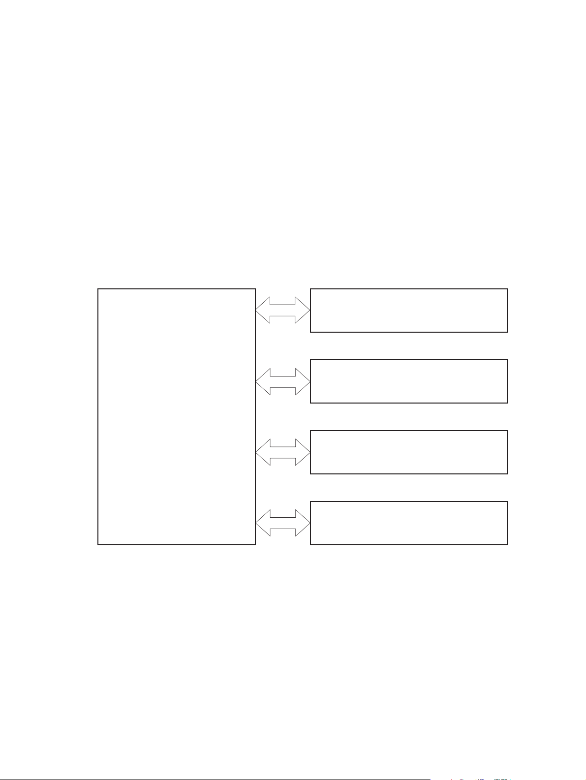
Basic operation
The product routes all high-level processes through the formatter, which stores font information,
processes the print image, and communicates with the host computer.
The basic product operation comprises the following systems:
The engine-control system, which includes the power supply and the DC controller printed circuit
●
assembly (PCA)
The laser/scanner system, which forms the latent image on the photosensitive drum
●
The image-formation system, which transfers a toner image onto the paper
●
The media feed system, which uses a system of rollers and belts to transport the paper through
●
the product
Option (optional paper feeder)
●
Figure 1-1 Relationship between the main product systems
Laser/scanner system
Engine control system
Image-formation system
Media-feed system
Option
2 Chapter 1 Theory of operation ENWW
Page 29

Sequence of operation
The DC controller PCA controls the operating sequence, as described in the following table.
Table 1-1 Sequence of operation
Period Duration Description
Waiting From the time the power is turned on, the
door is closed, or when the product exits
Sleep mode until the product is ready for
printing
Standby From the end of the waiting sequence or
the last rotation until the formatter
receives a print command or until the
product is turned off
Initial rotation From the time the formatter receives a
print command until the paper enters the
paper path
Printing From the time the first sheet of paper
enters the paper path until the last sheet
has passed through the fuser
Heats the fuser sleeve in the fuser
●
Pressurizes the pressure roller in
●
the fuser
Detects the print cartridges
●
Moves the ITB and developing unit
●
to the home position
Cleans the ITB and secondary
●
transfer roller
The product is in the READY state.
●
The product enters Sleep mode if
●
the sleep command is received
from the formatter.
The product calibrates if it is time for
●
an automatic calibration.
Activates the high-voltage power
●
supply
Prepares each laser/scanner unit
●
Warms the fuser to the correct
●
temperature
Forms the image on the
●
photosensitive drums
Transfers the toner to the paper
●
Fuses the toner image onto the
●
paper
Last rotation From the time the last sheet of paper
exits the fuser until the motors stop
rotating
Moves the last printed sheet into the
●
output bin
Stops the high-voltage power
●
supply
Stops each laser/scanner unit
●
If another print command is
●
received, the product enters the
initial rotation period when the last
rotation is complete.
ENWW Basic operation 3
Page 30
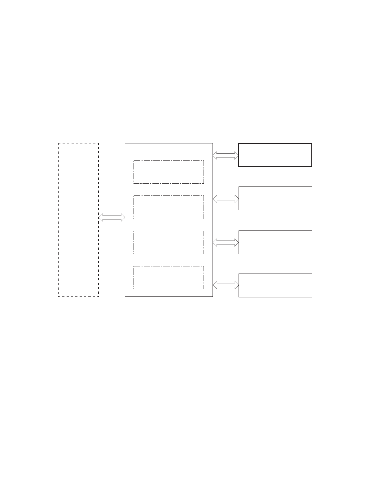
Engine-control system
The engine-control system receives commands from the formatter and interacts with the other main
systems to coordinate all product functions. The engine-control system consists of the following
components:
DC controller
●
Low-voltage power supply
●
High-voltage power supply
●
Fuser control
●
Figure 1-2 Engine-control system
Formatter
ENGINE CONTROL SYSTEM
DC controller
Low-voltage power supply
High-voltage power supply
Fuser control
LASER SCANNER SYSTEM
IMAGE-FORMATION SYSTEM
MEDIA FEED SYSTEM
OPTION
4 Chapter 1 Theory of operation ENWW
Page 31

DC controller
The DC controller controls the operational sequence of the product.
Figure 1-3 DC controller block diagram
Motor
Solenoid
Secondary
transfer roller
Print cartridge
(Y/M/C/Bk)
Motor
Fan
Photointerrupter
ITB unit
AC input
High-voltage
power supply T
High-voltage
power supply D
Fuser
Low-voltage
power supply
DC controller
ICB
Fan
Motor
Clutch
Solenoid
Switch
Photointerrupter
Sensor
LED
Option
Control panel
NVRAM
Solenoids
Table 1-2 Solenoids
Laser scanner unit
Component abbreviation Component name
SL1 Primary transfer roller disengagement solenoid
SL2 Duplex reverse solenoid (HP Color LaserJet CP4525dn, HP Color LaserJet CP4025dn, and
HP Color LaserJet CP4525xh only)
SL3 Multipurpose-tray pickup solenoid
SL4 Cassette pickup solenoid
Formatter
ENWW Engine-control system 5
Page 32

Clutches
Component abbreviation Component name
Switches
CL1 Duplex re-pickup clutch (HP Color LaserJet CP4525dn, HP Color LaserJet CP4025dn, and HP
Color LaserJet CP4525xh only)
Table 1-3 Switches
Component abbreviation Component name
SW1 5V interlock switch
SW2 24V interlock switch
SW3 Power switch
SW4 Cassette media size switch
SW5 Front door switch
SW6 Right door switch
Test print switch
6 Chapter 1 Theory of operation ENWW
Page 33

Sensors
Table 1-4 Sensors
Component abbreviation Component name
NPLED Media sensor
SR1 Yellow drum home position sensor
SR2 Magenta drum home position sensor
SR3 Cyan drum home position sensor
SR4 Black drum home position sensor
SR5 Fuser delivery sensor
SR6 Output bin full sensor
SR7 Fuser pressure release sensor
SR8 MP-tray-media-presence sensor
SR9 Primary-transfer-roller disengagement sensor
SR10 New ITB sensor
SR11 Developer alienation sensor
SR14 Loop sensor 1
SR15 Loop sensor 2
SR20 TOP (top of page) sensor
SR22 Duplex re-pickup sensor (HP Color LaserJet CP4525dn, HP Color LaserJet CP4025dn, and
SR23 Tray 2 paper surface 1 sensor
SR24 Tray 2 paper surface 2 sensor
SR25 Tray 2 paper present sensor
RD sensor
Environment sensor (temperature and humidity)
Yellow toner-level sensor
Magenta toner-level sensor
Cyan toner-level sensor
Black toner-level sensor
Residual toner full sensor
TH4 Laser scanner temperature sensor
HP Color LaserJet CP4525xh only)
ENWW Engine-control system 7
Page 34

Motors
The product has 13 motors. The motors drive the components in the paper-feed and image-formation
systems.
Table 1-5 Motors
Abbreviation Name Purpose Failure detection
M1 ITB motor Drives the ITB and residual
toner feed screw
M2 Fuser motor Drives the fuser sleeve,
pressure roller, fuser pressure
roller, and primary transfer
roller disengagement
M3 Y drum motor Drives the photosensitive
drum (yellow), developing
roller (yellow), and primary
charging roller (yellow)
M4 M drum motor Drives the photosensitive
drum (magenta), developing
roller (magenta), and primary
charging roller (magenta)
M5 C drum motor Drives the photosensitive
drum (cyan), developing roller
(cyan), and primary charging
roller (cyan)
M6 Bk drum motor Drives the photosensitive
drum (black), developing
roller (black), and primary
charging roller (black)
M7 Lifter motor Drives the lifter for the
cassette
Yes
Yes
Yes
Yes
Yes
Yes
Yes
M8 Cyan/black scanner motor Drives the scanner mirror in
M9 Yellow/magenta scanner
motor
M10 Developing disengagement
motor
M11 Duplex reverse motor (HP
Color LaserJet CP4525dn,
HP Color LaserJet
CP4025dn , and HP Color
LaserJet CP4525xh only)
M12 Residual toner-feed motor Drives the residual toner feed
M13 Pickup motor Drives the cassette pickup
the cyan/black laser scanner
Drives the scanner mirror in
the yellow/magenta laser
scanner
Drives the developing unit
disengagement
Drives the duplex reverse
roller and duplex feed roller
screw
roller, MP tray pickup roller,
feed roller, and cassette
separation roller
Yes
Yes
No
No
Yes
No
8 Chapter 1 Theory of operation ENWW
Page 35

Fans
The DC controller determines if a motor has failed and notifies the formatter when it encounters the
following conditions:
Startup failure: the motor does not reach a specified speed within a specified time from when the
●
motor starts.
Rotational failure: the rotational speed of the motor is not in the specified range for a specified time
●
after the motor reaches a specified speed.
Lock detection (for the residual toner feed motor): the value of the motor drive signal voltage is not
●
in the specified range for a specified time.
The product has four fans for preventing the temperature from rising in the product.
Table 1-6 Fans
Abbreviation Name Cooling area Type Speed
FM1 Power supply fan Around the power
supply unit
FM2 Cartridge fan Around the cartridges Intake Full/half
FM3 Delivery fan Around the delivery unit Intake Full/half
FM4 Exhaust fan 1 Around the cartridge Exhaust Full/half
Intake Full/half
The DC controller determines if there is a fan failure and notifies the formatter if the fan locks for a
specified time from when the fan starts.
ENWW Engine-control system 9
Page 36

High-voltage power supply
The DC controller controls the high-voltage power supply to generate biases. The high-voltage power
supply delivers the high-voltage biases to the following components used to transfer toner during the
image-formation process:
Primary-charging roller (in the cartridge)
●
Developing roller (in the cartridge)
●
Primary-transfer roller
●
Secondary-transfer roller
●
Figure 1-4 High-voltage power supply circuits
Primary transfer roller
Developing bias
circuit
Primary transfer
bias circuit
High-voltage power supply D
High-voltage power supply T
Secondary transfer
bias circuit
ITB
Secondary transfer roller
DC controller
Print cartridge
Primary charging
bias circuit
The high-voltage power supply contains several separate circuits.
Table 1-7 High-voltage power supply circuits
Circuit Description
Primary-charging-bias generation The primary charging bias negatively charges the surface of the photosensitive drum
to prepare for image formation. The primary-charging-bias circuit in the high-voltage
power supply generates the biases for each color.
Developing-bias generation The developing bias adheres toner to an electrostatic latent image formed on the
photosensitive drum. The developing-bias circuit in the high-voltage power supply
generates the biases for each color.
10 Chapter 1 Theory of operation ENWW
Page 37

Table 1-7 High-voltage power supply circuits (continued)
Circuit Description
Primary-transfer-bias generation The primary transfer bias transfers the toner from each photosensitive drum onto
the ITB. The primary transfer bias circuit in the high-voltage power supply generates
the biases for each color.
Secondary-transfer-bias generation The secondary transfer bias transfers the toner image from the ITB onto the paper.
The secondary transfer bias circuit in the high-voltage power supply generates the
bias. The reversed bias transfers residual toner on the secondary transfer roller back
to the ITB. The residual toner on the ITB is deposited in the toner collection box.
ENWW Engine-control system 11
Page 38

Low-voltage power supply
The low-voltage power-supply circuit converts the AC power from the wall receptacle into the DC voltage
that the product components use. The product has two low-voltage power-supplies for 110 Volt or 220
Volt input.
Figure 1-5 Low-voltage power-supply circuit
AC input
Fuse
DC controller
Fuse
Noise filter
Rectifying
Rectifying
circuit
+12V
generation
circuit
Low-voltage power supply
Noise filter
circuit
Protection circuit
Remote switch
control circuit
Power switch
Zerocross
circuit
+24V
generation
circuit
Fuser control
Protection circuit
+3.3V
generation
circuit
circuit
+5V
generation
circuit
PSTYP100
ZEROX
24RMT
+24VA
+5VB
+3.3V
Switching
PWROFF
PWRSWON
+12VA
circuit
ICB
+24VB
SW2
SW1
+5VC
+3.3VS
Formatter
The low-voltage power supply converts the AC power into three DC voltages, which it then subdivides,
as described in the following table.
Table 1-8 Converted DC voltages
Main DC voltage Sub-voltage Behavior
+24 V +24 VA Constantly supplied
12 Chapter 1 Theory of operation ENWW
Page 39

Table 1-8 Converted DC voltages (continued)
Main DC voltage Sub-voltage Behavior
+24 VB Interrupted when the front door or right
door open
+5 V +5 VB Constantly supplied
+5 VC Interrupted when the front door or right
+3.3 V 3.3 V Constantly supplied
3.3 VS Stopped during Sleep (powersave)
Overcurrent/overvoltage protection
The low-voltage power supply stops supplying the DC voltage to the product components whenever it
detects excessive current or abnormal voltage from the power source. If DC voltage is not being supplied
from the low-voltage power supply, the protective function might be running. In this case, turn the power
off and unplug the power cord. Do not turn the power switch on until the root cause is found. The DC
controller notifies the formatter of a low-voltage power supply failure when the protective function is
activated. In addition, the low-voltage power supply circuit and the fuser control unit have a fuse to
protect against overcurrent. If overcurrent flows into the AC line, the fuse blows to stop AC power.
Safety
For personal safety, the product interrupts 24 VB power to the fuser, high-voltage power supply, and
motors, in addition to +5 VC to the laser scanners when the front or right door is opened. The power
switch is on the dc line so that the ac power flows even if the power switch is turned off. Unplug the
power cord before disassembling the product.
door open
mode
Voltage detection
The product detects the power supply voltage that is connected to the product. The DC controller
monitors the POWER SUPPLY VOLTAGE (PSTYP100) signal and detects power supply voltage,
whether 100 V or 200 V, to control the fuser operation.
Sleep (powersave) mode
Sleep mode conserves energy by stopping the power to several components when the product is idle.
If the DC controller detects voltage that is too high when the product is in Sleep mode, it determines
that the low-voltage power supply has failed, and it notifies the formatter.
Low-voltage power supply failure
The DC controller determines a low-voltage power supply failure and notifies the formatter when the
low-voltage power supply does not supply +24 V.
ENWW Engine-control system 13
Page 40

Fuser control
The fuser heater-control circuit and the fuser heater safety circuit control the fuser temperature according
to commands from the DC controller.
Figure 1-6 Fuser components
TH2
Table 1-9 Fuser components
Type of component Abbreviation Name Function
H1
TH1
Fuser sleeve
TP1
TH3
CONTROL signal
FUSER TEMPERATURE signal
Pressure roller
Low-voltage power
FUSER HEATER
supply unit
Fuser heater
control circuit
DC controller
Fuser heater
safety circuit
Heaters H1 Fuser heater Heats the fuser sleeve.
Thermistors
(Contact type)
Thermoswitches
(Contact type)
TH1 Main thermistor Detects the center temperature of
the fuser sleeve.
TH2 Sub thermistor 1 Detects the temperature at one
end of the fuser heater.
TH3 Sub thermistor 2
TP1 For the fuser heater Controls the fuser-roller main
heater
14 Chapter 1 Theory of operation ENWW
Page 41

Fuser temperature control
The fuser temperature control maintains the target surface temperature of the fuser sleeve.
Figure 1-7 Fuser temperature-control circuit
Fuser
Fuser sleeve unit
TH1
TH2
TH3
Pressure
roller
H1: Fuser heater
TP1: Thermoswitch
TH1: Main thermistor
TH2: Sub thermistor 1
TH3: Sub thermistor 2
TP1
H1
Fuse
Fuser heater
control circuit
Current
detection
circuit
Fuser heater safety circuit
Relay
Fuser heater safety circuit
Low-voltage power supply
Zerocross
circuit
Relay
control
circuit
Relay
FSR_CURRMS
Fuser control circuit
/ZEROX
FSRD1
/RLD
FSRSAFE1
FSRSAFE2
/FSRNEW
/FSRSNS
FSRTH3
FSRTH2
FSRTH1
CPU
Fuser heater
safety circuit
Fuser sleeve temperature protection
The fuser heater controls the temperature of the fuser sleeve. The DC controller detects the center area
temperature by monitoring the main thermistor. The DC controller controls the FIXING HEATER
CONTROL (FSRD1) signal, so that the fuser sleeve remains at the targeted temperature.
Protective function: The protective function detects rising temperatures in the fuser and interrupts
●
power to the fuser heater. The following four protective components prevent the fuser sleeve and
pressure roller from excessive rising temperature:
DC controller
◦
Fuser heater safety circuit
◦
DC controller
ENWW Engine-control system 15
Page 42

Current detection circuit
◦
Thermoswitch
◦
DC controller: The DC controller monitors the detected temperature of the main thermistor and
●
sub thermistors. The DC controller deactivates the FIXING HEATER CONTROL signal and
releases the relay to interrupt power supply to the fuser heater under the following conditions:
TH1: 230° C (446° F) or higher
◦
TH2: 285° C (545° F) or higher
◦
TH3: 285° C (545° F) or higher
◦
Fuser-heater safety circuit: The fuser heater safety circuit monitors the detected temperature of
●
the sub thermistors. The fuser heater safety circuit releases the relay to interrupt power supply to
the fuser heater under the following conditions:
TH2: 290° C (554° F) or higher
◦
TH3: 290° C (554° F) or higher
◦
Current-detection protection circuit: The current detection circuit monitors the current flowing
●
through the fuser heater control circuit. The current detection circuit deactivates the fuser heater
control circuit to interrupt power supply to the fuser heater when it detects the current higher than
a specified value.
Thermoswitch: If the temperature in the heaters is abnormally high, and the temperature in the
●
thermoswitches exceeds a specified value, the contact to the thermoswitch breaks. Following are
the thresholds for each thermoswitch:
◦
NOTE: When the thermoswitches reach this temperature, the temperature on the fuser rollers is about
320° C (608° F).
Failure detection
The DC controller determines a fuser unit failure, deactivates the FIXING HEATER CONTROL signal,
releases the relay to interrupt power supply to the fuser heater, and notifies the formatter of a failure
status when it encounters any of following conditions:
Abnormally high temperatures: Temperatures are too high for any of the following components,
●
at any time:
◦
◦
◦
Abnormally low temperatures: Temperatures are too low at any of the following components
●
after the product has initialized.
TP1: 270° C (518° F) or higher
TH1: 230° C (446° F) or higher
TH2: 285° C (545° F) or higher
TH3: 285° C (545° F) or higher
TH1: 120° C (248° F) or lower
◦
TP2 or TP3: 100° C (212° F) or lower
◦
Abnormal temperature rise: The DC controller determines an abnormal temperature rise if the
●
detected temperature of TH1 does not rise 2° C within a specified time after the fuser motor is
16 Chapter 1 Theory of operation ENWW
Page 43

turned on, or if the detected temperature of the thermistors does not rise to a specified temperature
for a specified time after the fuser motor is turned on.
Thermistor open: The DC controller determines a thermistor open if:
●
The detected temperature of TH1 is kept at 12° C (53° F) or lower for a specified time after
◦
the fuser motor is turned on.
The detected temperature of TH2 is kept at 4° C (39° F) or lower for a specified time.
◦
The detected temperature of TH3 is kept at 4° C (39° F) or lower for a specified time.
◦
Drive-circuit failure: The DC controller determines a drive-circuit failure:
●
If the detected power supply frequency is out of a specified range when the product is turned
◦
on or during the standby period
If the current detection circuit detects an out of specified current value
◦
Fuser discrepancy: The DC controller determines a fuser type mismatch when it detects an
●
unexpected power supply voltage.
Fuser unit identification
The product detects the type and presence of the fuser. The DC controller detects whether the fuser is
installed and its type by monitoring the FIXING UNIT IDENTIFICATION (FSRSNS) signal when the
product is turned on or when the right door is closed. The DC controller determines a low-voltage power
supply failure and notifies the formatter when it fails to detect the type or presence of the fuser.
NOTE: This product detects if the correct fuser for the product is installed. The fuser from a different
product (for example, the HP Color LaserJet CP 3525 Series printer) can be installed in this product,
but it will not correctly function.
Fuser unit life detection
The product detects the remaining life of a fuser. The DC controller recognizes a new fuser from the
NEW FIXING UNIT (/FSRNEW) signal. The DC controller determines a fuser's end of life and then
notifies the formatter when a specified number of pages has been printed after the fuser was replaced.
NOTE: The product detects a new fuser using a fusible link that blows after 100 pages of printing. If
a new fuser is installed for troubleshooting purposes, be sure to remove it before printing 100 pages.
ENWW Engine-control system 17
Page 44

Laser/scanner system
The laser/scanner system forms the latent electrostatic image on the photosensitive drums according
to the VIDEO signals sent from the formatter. The product has two laser/scanners: one for yellow and
magenta and the other for cyan and black.
The main components of the laser/scanner system are the laser unit and the scanner motor unit, which
are controlled by the signals sent from the DC controller.
Figure 1-8 Laser/scanner system
Photosensitive drum (Y)
BD sensor
Yellow laser
Magenta laser
Photosensitive drum (M)
Laser unit
VIDEO signal
Scanner motor unit
SCANNER MOTOR
LASER CONTROL signal
BDI signal
CONTROL signal
DC controller
Formatter
Protective glass
Scanner mirror
18 Chapter 1 Theory of operation ENWW
Page 45

Laser/scanner failure
The DC controller determines that a laser/scanner has failed when any of the following conditions
occurs:
Laser failure: The detected laser intensity does not match a specified value when the product
●
initializes.
Scanner motor startup failure: The scanner motor does not reach a specified rotation within a
●
specified period from when the laser scanner starts driving.
Scanner-motor abnormal rotation: When a specified BD interval is not detected during a print
●
operation, a BD error is determined. If the BD interval does not recover within a specified period
after the BD error occurs, the product determines a scanner motor abnormal rotation.
The laser/scanner system does not have a mechanical laser shutter. For safety reason, the product has
a interlock switch. The interlock switch is turned off to interrupt +5 V power supply to the laser/scanner
system, when the front or right door is open.
Protective-glass cleaners
Each laser/scanner has two openings which allow the laser beam to pass to the surface of the
photosensitive drum. These openings are covered by protective glass. When the protective glass gets
dirty (for example, by paper dust or toner) a protective-glass cleaner (PGC) cleans them.
NOTE: When a glass is dirty, streaks appear on the printed page in the process direction.
The PGC is a cleaning pad which slides along the laser shutter. With the front door open, the laser
shutter is positioned over the glass. As a print cartridge is inserted, the cleaning pad is pushed down
and wipes the glass. When the front door is closed after cartridge insertion, the laser shutter (and PGC)
move away from the glass which allows the laser beam to pass through the glass.
When the front door is opened, the laser shutter and PGC move back into position over the glass. When
the cartridge is pulled out, the cleaning pad is returned to its starting position at the front of the cartridge
opening.
ENWW Laser/scanner system 19
Page 46

Figure 1-9 Protective-glass cleaners (PGCs)
20 Chapter 1 Theory of operation ENWW
Page 47

Image-formation system
The image-formation system creates the printed image on the paper. The system consists of the
following components:
Print cartridges
●
ITB
●
Secondary transfer roller
●
Fuser
●
Laser /scanner units
●
The DC controller controls the laser scanner unit and each of the high-voltage power supplies to form
the toner image on the photosensitive drum surface, according to the VIDEO signals. The toner image
is then transferred to the print-media and fused.
Figure 1-10 Image-formation system
High-voltage power supply T
Laser scanner unit
ITB
Laser scanner unit
High-voltage power supply D
Fuser
Secondary
transfer roller
DC controller
Print cartridge
ENWW Image-formation system 21
Page 48

Figure 1-11 Image-formation drive system
Primary
charging
roller
Developing
roller
Primary
charging
roller
Developing
roller
Developing
Primary
charging
roller
roller
Fuser motor
M2
Primary
charging
roller
Developing
roller
M3
Y drum motor
M4
M drum motor
M5
C drum motor
M6
Bk drum motor
M1
ITB motor
22 Chapter 1 Theory of operation ENWW
Page 49

Image-formation process
The image-formation system consists of ten steps divided into six functional blocks.
Figure 1-12 Image-formation process
: Media path
: Direction of drum rotation
: Block
Delivery
: Step
Fuser
ITB cleaning
9. ITB cleaning
5. Primary transfer
10. Drum cleaning
4. Developing
Developing
3. Laser beam exposure
Latent image formation
Functional block Steps Description
Latent image formation 1. Pre-exposure
2. Primary charging
1. Pre-exposure
2. Primary charging
Transfer
6. Secondary transfer
Drum cleaning
Pickup
An invisible latent image forms on the
surface of the photosensitive drums.
8. Fusing
7. Separation
Registration
3. Laser-beam exposure
Development 4. Development Toner adheres to the electrostatic latent
image on the photosensitive drums.
Transfer 5. Primary transfer
6. Secondary transfer
7. Separation
Fusing 8. Fusing The toner fuses to the paper to make a
ITB cleaning 9. ITB cleaning Residual toner is removed from the ITB.
Drum cleaning 10. Drum cleaning Residual toner is removed from the
The toner image transfers to the ITB and
later to the paper.
permanent image.
photosensitive drums.
ENWW Image-formation system 23
Page 50

Step 1: Pre-exposure
Light from the pre-exposure LED strikes the surface of the photosensitive drum to remove any residual
electrical charges from the drum surface.
Figure 1-13 Pre-exposure
LED
Photosensitive drum
Step 2: Primary charging
The primary-charging roller contacts the photosensitive drum and charges the drum with negative
potential.
Figure 1-14 Primary charging
Primary charging roller
Photosensitive drum
Primary charging bias
24 Chapter 1 Theory of operation ENWW
Page 51

Step 3: Laser-beam exposure
The laser beam strikes the surface of the photosensitive drum in the areas where the image will form.
The negative charge neutralizes in those areas, which are then ready to accept toner.
Figure 1-15 Laser-beam exposure
Step 4: Development
Toner acquires a negative charge as the developing cylinder contacts the developing blade. Because
the negatively charged surface of the photosensitive drums have been neutralized where they have
been struck by the laser beam, the toner adheres to those areas on the drums. The latent image
becomes visible on the surface of each drum.
Laser beam
Figure 1-16 Development
Developing blade
Developing roller
Developing bias
Photosensitive drum
ENWW Image-formation system 25
Page 52

Step 5: Primary transfer
The positively charged primary-transfer rollers contact the ITB, giving the ITB a positive charge. The
ITB attracts the negatively charged toner from the surface of each photosensitive drum, and the
complete toner image transfers onto the ITB.
Figure 1-17 Primary transfer
Primary transfer bias
Primary transfer roller
ITB
Photosensitive
drum
Step 6: Secondary transfer
The paper acquires a positive charge from the secondary-transfer roller, and so it attracts the negatively
charged toner from the surface of the ITB. The complete toner image transfers onto the paper.
Figure 1-18 Secondary transfer
Secondary transfer
opposed roller
Paper
Secondary transfer bias
ITB
Secondary transfer roller
26 Chapter 1 Theory of operation ENWW
Page 53

Step 7: Separation
The stiffness of the paper causes it to separate from the ITB as the ITB bends. The static-charge
eliminator removes excess charge from the paper to make sure that the toner fuses correctly.
Figure 1-19 Separation
Paper
Secondary transfer roller
Step 8: Fusing
To create the permanent image, the paper passes through heated, pressurized rollers to melt the toner
onto the page.
Secondary transfer
opposed roller
ITB
Static charge
eliminator
Figure 1-20 Fusing
Fuser heater
Fuser sleeve
Toner
Paper
Pressure roller
ENWW Image-formation system 27
Page 54

Step 9: ITB cleaning
The cleaning blade scrapes the residual toner off the surface of the ITB. The residual toner feed screw
deposits residual toner in the toner collection box.
Figure 1-21 ITB cleaning
Residual toner feed screw
Cleaning blade
Step 10: Drum cleaning
The cleaning blade scrapes the residual toner off the surface of the photosensitive drum, and toner is
deposited in the toner collection box in the cartridge.
Figure 1-22 Drum cleaning
Cleaning blade
ITB
CRG toner collection box
Print cartridge
Each print cartridge is filled with toner and consists of the following components:
Photosensitive drum
●
Developing unit
●
Developing roller
●
Primary-charging roller
●
Photosensitive
drum
28 Chapter 1 Theory of operation ENWW
Page 55

The DC controller rotates the drum motor to drive the photosensitive drum, developing roller, and the
primary-charging roller.
Figure 1-23 Print-cartridge system
DC controller
M10
Developing
disengagement
motor
Developing unit
SR11:
Developing disengagement sensor
SR1/SR2/SR3/SR4:
Drum home position sensor
M3/M4/M5/M6:
Drum motor
Primary charging roller
Memory
tag
Developing roller
The DC controller rotates the drum motor to drive the photosensitive drum, developing unit, and primary
charging roller.
The memory tag is a non-volatile memory chip that stores information about the usage for the print
cartridge. The product reads and writes the data in the memory tag.
ENWW Image-formation system 29
Page 56

The DC controller determines a memory tag error and notifies the formatter when it fails to either read
from or write to the memory tag.
Cartridge presence detection: The DC controller detects the presence of the cartridges by
●
monitoring the memory tag. The DC controller notifies the formatter when a cartridge is missing or
installed in the incorrect slot.
Toner level detection: The DC controller detects the remaining toner in a cartridge by the optical
●
detection method and then notifies the formatter of the remaining toner level.
Cartridge life detection: The DC controller detects the cartridge life by monitoring the total operating
●
time or remaining toner level of the print cartridge. The DC controller determines a cartridge end
of life and notifies the formatter when total operating time of the cartridge reaches a specified time
or the cartridge runs out of toner.
Developing-roller engagement and disengagement
The product can print in full-color mode or in black-only mode. To print in black-only mode, the product
disengages the developing rollers in the cyan, magenta, and yellow print cartridges which maximizes
the life of the cartridges.
Figure 1-24 Developing-roller engagement and disengagement control
DC controller
Developing
M10
disengagement
motor
Developing unit
SR11
Developing disengagement sensor
Developing unit is disengaged
Photosensitive drum
Developing disengagement cam
Developing unit is engaged
30 Chapter 1 Theory of operation ENWW
Page 57

The developing-roller engagement and disengagement control operates as follows: When the product
is turned on and when each print job is completed, all four of the developing units are disengaged from
the photosensitive drums.
The drive of the developing disengagement motor rotates the developing disengagement cam.
●
As the cam rotates, the developing unit engages with or separates from the photosensitive drum.
●
When the print mode is full color, the developing units engage with the drums. When the print mode is
black-only, only the black developing units engages with the drum.
The DC controller determines a developing disengagement motor failure and notifies the formatter when
it does not detect a specified signal from the developing disengagement sensor during the developing
unit engagement and disengagement operation.
Intermediate transfer belt (ITB) unit
The ITB unit accepts the toner images from the photosensitive drums and transfers the completed image
to the paper. The ITB unit has the following main components:
ITB
●
ITB drive roller
●
ITB-drive roller
●
Primary-transfer roller
●
ITB cleaner
●
The ITB motor drives the ITB drive roller, which rotates the ITB. The motion of the ITB causes the primary
transfer rollers to rotate. The ITB cleaner cleans the ITB surface.
Figure 1-25 ITB unit
DC controller
ITB
ITB cleaner
M1
ITB motor
ITB drive roller
Primary transfer roller
ENWW Image-formation system 31
Page 58

Primary-transfer-roller engagement and disengagement
The sequence of the primary-transfer-roller engagement and disengagement control is as follows:
1. The fuser motor turns on the primary-transfer disengagement solenoid and rotates the primary-
transfer-roller disengagement cam.
2. As the cam rotates, the Y/M/C primary-transfer-roller slide plate or the Bk primary-transfer-roller
slide plate moves to the right or left, which causes the primary-transfer roller to move up or down.
3. The ITB engages with or separates from the photosensitive drum depending on the movement of
the primary-transfer rollers.
Depending on the requirements of the print job, the primary-transfer rollers engage with the ITB so it
can receive toner from the photosensitive drums. The primary-transfer roller has three engagement
states.
Table 1-10 Primary-transfer-roller engagement states
All rollers disengaged The ITB is disengaged from all the four photosensitive drums. This state is the home
All rollers engaged The ITB is engaged with all four photosensitive drums. The state for full-color
Black roller engaged The ITB is engaged with only the black photosensitive drum. The state for black-
position for the ITB unit.
printing.
color mode printing .
The DC controller determines a primary-transfer-roller disengagement failure and notifies the formatter
when it does not detect a signal from the primary-transfer disengagement sensor even though the
primary-transfer disengagement solenoid is turned on.
If the DC controller does not receive the expected signal from the ITB home-position sensor when the
primary-transfer-roller engages or disengages, but the primary-transfer-roller disengagement motor is
rotating, the DC controller determines that the primary-transfer-disengagement mechanism has failed,
and notifies the formatter.
The DC controller detects whether the ITB unit is new by monitoring the new ITB unit sensor. The DC
controller determines the ITB unit is at end of life and notifies the formatter when a specified number of
pages are printed after the ITB unit is replaced. If swapping ITB units between two products for
troubleshooting purposes, be sure to return the ITB units to their original products to maintain the correct
life count.
NOTE: A new ITB has a flag that causes the ITB life counter to be reset. When an ITB is installed in
the product, it cannot be removed and used again as a new ITB.
The DC controller detects the presence of an ITB unit by monitoring the primary-transfer-roller
disengagement sensor. The DC controller turns on the primary-transfer disengagement solenoid for
specified times during an initial rotation period when the following events occur:
The product is turned on.
●
The product exits sleep mode.
●
The door is closed.
●
The DC controller determines the absences of an ITB unit and notifies the formatter when it does not
detect a specified signal from the new primary transfer-roller disengagement sensor.
32 Chapter 1 Theory of operation ENWW
Page 59

Figure 1-26 Three states of primary-transfer-roller engagement and disengagement
DC controller
Fuser motor
M2
SL1
Primary transfer
disengagement solenoid
<All colors are disengaged>
Photosensitive drum
<All colors are engaged>
ITB
SR9:
Primary transfer
disengagement sensor
Primary transfer roller
Primary transfer roller disengagement cam
YMC primary transfer roller slide plate
<Only black is engaged>
Bk primary transfer roller slide plate
ENWW Image-formation system 33
Page 60

ITB cleaning
The cleaning blade in the ITB cleaner scrapes the residual toner off the ITB surface. The residual toner
feed screw deposits the residual toner to the residual toner feed unit. The ITB motor and the residual
toner feed motor drive the screw. The DC control detects whether the toner collection box is full, using
the residual-toner full sensor, and then notifies the formatter.
Figure 1-27 ITB cleaning process
Cleaning blade
ITB cleaner
ITB motor
Calibration
The product calibrates itself to maintain excellent print quality. Calibration corrects color-misregistration
and color-density variation.
During calibration, the product places a specific pattern of toner on the surface of the ITB. Sensors at
the end of the ITB read the toner pattern to determine if adjustments are necessary.
M1
Residual toner
feed screw
M12
Residual toner
feed motor
DC controller
Residual toner full sensor
ITB
Residual toner feed unit
Toner collection box
NOTE: The product performs a drum-speed adjustment (DSA) during the full calibration operation.
The DSA compensates for variations between each drum and the speed of the ITB surface.
34 Chapter 1 Theory of operation ENWW
Page 61

Color-misregistration control
Internal variations in the laser/scanners can cause the toner images to become misaligned. The colormisregistration control corrects the following problems:
Horizontal scanning start position
●
Horizontal scanning magnification
●
Vertical scanning start position
●
The DC controller forms a pattern of toner on the surface of the ITB and measures a misaligned length
with the RD sensor.
Figure 1-28 Toner patterns for calibration
RD sensor
The DC controller signals the formatter to perform the color-misregistration control when one of the
following events occur:
A cartridge or the ITB is replaced.
●
A specified number of pages have printed.
●
The formatter sends a command.
●
The DC controller determines an RD sensor failure and notifies the formatter if it detects data from the
RD sensor that is not in a specified range, when the product is turned on or when the colormisregistration control starts.
ITB
Pattern of toner
Image-stabilization control
NOTE: The product contains a thermal sensor, located within the TCU level detection sensor, which
monitors the temperature in the cartridge area and uses this information to make adjustments during
CPR control.
ENWW Image-formation system 35
Page 62

Environmental changes or deterioration of the photosensitive drums and toner can cause variations in
the image density. The image-stabilization control reduces these fluctuations.
Table 1-11 Image-stabilization controls
Image density control (DMAX) This control corrects variations in image density related to deterioration of the
Image halftone control (DHALF) The formatter performs this control to calibrate the halftone, based on the halftone-
photosensitive drum or the toner. The DC controller adjusts the high-voltage biases
to correct the problem under the following conditions:
The image-stabilization control calibrates each high-voltage bias to stabilize the
fluctuations in image density caused by deterioration of the photosensitive drums or
toner or because of environmental changes. The DC controller determines the
product's environment based on the surrounding temperature and humidity data
from the environment sensor. The DC controller calibrates the biases according to
the detected environment and usage condition of the print cartridge to obtain an
appropriate image. The DC controller determines an environment sensor failure and
notifies the formatter when it detects environmental data from the environment
sensor with out of specified value. The DC controller commands the formatter to
control the image density under the following conditions
The temperature of the main thermistor is too low when the product is turned
●
on.
A print cartridge or the ITB is replaced.
●
A specified number of pages have printed.
●
After a specific period of the completion of a previous DMAX
●
The environment changes for a specified condition after a previous DMAX.
●
density measurements, under the following conditions:
The formatter sends a command.
●
DMAX is completed.
●
The DC controller determines an RD sensor failure and notifies the formatter if it
detects data from the RD sensor out of a specified range.
The DC controller determines a RD sensor failure and notifies the formatter if it detects an out-ofspecified-data value from the RD sensor when the product is turned on or when the color misregistration
control starts.
36 Chapter 1 Theory of operation ENWW
Page 63

Pickup, feed, and delivery system
The pickup, feed, and delivery system uses a series of rollers to move the paper through the product.
Figure 1-29 Paper path
Duplex model only
Simplex media path
Duplex media path
Reverse roller
Pressure roller
Fuser sleeve
Secondary transfer roller
MP tray pickup roller
Cassette feed roller
Cassette pickup roller
MP tray separation pad
Cassette separation roller
ENWW Pickup, feed, and delivery system 37
Page 64

Figure 1-30 Switches and sensors for the pickup, feed, and delivery system
Duplex model only
SR6
SR5
SR14
SR15
SR20
SW4
SR25
SR23
SR24
SR22
Media sensor
SR8
Table 1-12 Switches and sensors for the pickup, feed, and delivery system
Abbreviation Component
SR5 Fuser delivery sensor
SR6 Delivery tray media full sensor
SR8 MP tray media presence sensor
SR14 Loop sensor 1
SR15 Loop sensor 2
SR20 TOP (top of page) sensor
SR21 MP tray media-presence sensor
SR22 Duplex re-pickup sensor (duplex models only)
SR23 Cassette-media stack-surface sensor 1
SR24 Cassette-media stack-surface sensor 2
SR25 Cassette presence sensor
SW4 Cassette media size switch
Media sensor
38 Chapter 1 Theory of operation ENWW
Page 65

Figure 1-31 Motors and solenoids for the pickup, feed, and delivery system
M2 M11
Duplex model only
SL2
Duplex flapper
M1
Pickup arm
SL4
Lifter
M7
M13
Table 1-13 Motors and solenoids for the pickup, feed, and delivery system
Abbreviation Component
M1 ITB motor
M2 Fuser motor
M7 Lifter motor
M11 Duplex reverse motor (duplex models only)
M13 Pickup motor
CL1 Duplex re-pickup clutch (duplex models only)
SL2 Duplex reverse solenoid (duplex models only)
SL3 Multipurpose tray pickup solenoid
SL4 Cassette pickup solenoid
CL1
SL3
ENWW Pickup, feed, and delivery system 39
Page 66

The pickup, feed, and delivery system is divided into the following three blocks:
Pickup-and-feed block: From each pickup source to the fuser inlet
●
Fuser-and-delivery block: From the fuser to the delivery destination
●
Duplex block: From the duplex reverse unit to duplex re-pickup unit (for duplex models only)
●
Figure 1-32 Three main units of the pickup, feed, and delivery system
Fusing-and-delivery block
Duplex block
Pickup-and-feed block
40 Chapter 1 Theory of operation ENWW
Page 67

Pickup-and-feed unit
The pickup-and-feed unit picks an individual sheet of paper from the multipurpose tray or the cassettes,
carries it through the secondary-transfer unit, and feeds it into the fuser.
Figure 1-33 Pickup-and-feed unit
Simplex media path
Duplex media path
Pickup-and-feed block
Cassette pickup
The sequence of steps for the cassette-tray pickup operation is the following:
1. The product is turned on or the cassette is inserted.
2. The cassette lift-up operation raises the lifting plate so paper can be picked up.
3. The pickup motor rotates when a print command is received from the formatter.
4. The cassette pickup roller, cassette feed roller, and cassette separation roller rotate.
5. The cassette pickup solenoid turns on at a specified time.
6. The cassette pickup cam rotates.
ENWW Pickup, feed, and delivery system 41
Page 68

7. As the pickup arm lowers, the cassette pickup roller touches the surface of the paper stack.
8. One sheet of paper feeds into the product.
Figure 1-34 Cassette-pickup mechanism
DC controller
Cassette pickup cam
SL1
Cassette pickup solenoid
Cassette-presence detection
The product detects the size of the paper loaded in the cassette and the presence of the cassette by
monitoring the cassette media size switch. The DC controller notifies the formatter when it determines
the absence of the cassette.
Pickup motor
Cassette feed roller
Cassette pickup roller
Pickup arm
M13
Cassette pickup solenoid
Cassette separation roller
Cassette feed roller
Pickup arm
Cassette pickup roller
Cassette separation roller
Paper size Cassette media size switch
Top switch
Universal ON ON ON
A5 OFF OFF ON
B5 OFF ON ON
Executive ON OFF ON
Letter OFF ON OFF
A4 ON OFF OFF
Legal ON ON OFF
Cassette absence OFF OFF OFF
Center switch Bottom switch
42 Chapter 1 Theory of operation ENWW
Page 69

Cassette lift operation and cassette paper-presence detection
The product keeps the paper stack surface at the correct pickup position. The cassette lift-up operation
is performed under the following conditions:
The product is turned on
●
The cassette is inserted
●
The paper stack surface in the cassette lowers
●
Figure 1-35 Cassette lift mechanism
DC controller
SR23
Cassette media
Lifter motor
presence sensor
M7
SR1
Cassette media stack surface sensor 1
Cassette media stack surface sensor 2
SR24
Lifting plate
The operational sequence of the cassette lift-up is as follows:
1. The lifter motor rotates and the lifter moves up.
2. When the cassette-media stack surface sensor 2 detects the stack surface of media, the lifter motor
stops.
3. The lifter motor rotates again to lift the lifter when the cassette-media stack surface sensor 1 detects
the stack surface and then lowers during printing.
When a cassette-media stack surface sensors does not detect the stack surface within a specified time
period after the lifter motor starts rotating, the DC controller determines a lifter motor failure and notifies
the formatter
Cassette multiple-feed prevention
In the cassette, a separation roller prevents multiple sheets of paper from entering the paper path. The
cassette pickup roller drives the separation roller through a sheet of paper.
The rotation of the cassette feed roller through the sheet drives the cassette separation roller. Because
it is equipped with a torque limiter, only one sheet is fed into the product.
Cassette media stack surface sensor lever
Cassette media presence sensor lever
Lifter
ENWW Pickup, feed, and delivery system 43
Page 70

The low friction force between the sheets weakens the driving force from the cassette feed roller.
Therefore, the separation roller is driven by its own driving force and holds back any multiple-fed sheets
from the cassette.
Figure 1-36 Multiple-feed prevention
Cassette feed roller
Cassette pickup roller
Cassette separation roller
follows the cassette feed roller
Driving force from
Print-media
Cassette separation roller
Normal-feed
the pickup motor
Multiple-feed
Multipurpose tray pickup
The product picks up one sheet of paper from the MP tray.
The sequence of steps for the multipurpose tray pickup operation as follows:
1. The pickup motor reverses when a print command is received from the formatter.
2. When the DC controller turns on the MP tray pickup solenoid, the MP tray pickup roller rotates and
the lifting plate lifts.
3. As the lifting plate rises, the paper is picked up.
4. The multipurpose tray separation pad removes any multiple-fed sheets, and one sheet is fed into
the product.
44 Chapter 1 Theory of operation ENWW
Page 71

The MP-tray media-presence sensor (SR8) detects whether paper is present in the MP tray.
Figure 1-37 Multipurpose tray pickup mechanism
DC controller
Paper feed
After the pickup operation, the paper feeds through the product and into the fuser.
Pickup motor
MP tray pickup solenoid
MP tray pickup roller
MP tray separation pad
M13
SL2
MP tray media presence sensor
SR8
Lifting plate
1. The paper picked up from the cassette is fed to the registration unit as the pickup motor rotates.
The paper picked up from the multipurpose tray is fed to the registration unit as the pickup motor
rotates. The duplex model has the duplex feed clutch. The driving force of the pickup motor is
transmitted to the duplex re-pickup roller by turning on the clutch.
2. The registration shutter corrects the skew-feed.
3. When the TOP sensor detects the leading edge of paper, the DC controller stops the paper so that
the media sensor detects the type of paper.
4. The DC controller controls the rotational speed of the pickup motor to align the paper with the
leading edge of the toner image on the ITB.
5. The ITB motor rotates the ITB.
6. The toner image on the ITB is transferred onto the paper, and the paper is fed to the fuser.
ENWW Pickup, feed, and delivery system 45
Page 72

The DC controller notifies the formatter of a paper size mismatch error when the paper length detected
by the TOP sensor does not match the paper size specified by the formatter.
Figure 1-38 Paper-feed mechanism
DC controller
ITB
M1
Pickup motor
M13
TOP sensor
SR20
Duplex re-pickup clutch
CL1
Media sensor
Registration shutter
Duplex re-pickup roller
Registration front feed roller
ITB motor
46 Chapter 1 Theory of operation ENWW
Page 73

Skew-feed prevention
The product can straighten the paper without slowing the feed operation.
1. The leading edge of paper strikes the registration shutter, and the leading edge is aligned with the
shutter.
2. As the feed rollers keep pushing the paper, the paper warps.
3. When the force is great enough, the registration shutter opens, and the paper passes through and
straightens
Figure 1-39 Skew-feed prevention
Registration shutter
Registration shutter
Paper
Paper
Paper detection
The product detects the type of paper by monitoring the media sensor. The media sensor detects the
glossiness of paper by the reflected light and the thickness of paper by transmitted light. The DC
controller identifies the type of paper (for example, plain paper, light paper, heavy paper, glossy paper,
ENWW Pickup, feed, and delivery system 47
Page 74

glossy film, or overhead transparency) and switches to the correct print mode. The DC controller
determines a media mismatch error and notifies the formatter under the following condition:
Simplex printing
The specified print mode is overhead transparency (OHT), but the media sensor detects another
●
paper type.
The specified print mode is not auto or OHT, but the media sensor detects OHT.
●
Duplex printing
The media sensor detects OHT.
●
The DC controller flashes the media sensor during the initial rotation period under the following
conditions:
The product is turned on
●
The product exits Sleep mode
●
When the light intensity is not a specified value, the DC controller determines a media-sensor failure
and notifies the formatter.
Feed speed control
For the best print quality, the product adjusts the feed speed depending on the paper type.
Table 1-14 Print mode and feed speed
Print mode Feed speed Media sensor detection
Normal 1/1 Yes
Heavy media 1 3/4
Heavy media 2 1/2 Yes
Heavy media 3 1/3 Yes
Light media 1 1/1 Yes
Glossy media 1 1/3 Yes
Glossy media 2 1/3 Yes
Glossy media 3 1/4 Yes
Glossy film 1/4 Yes
Envelope 1/2 No
OHT 1/4 Yes
Label 1/2 No
Designated media 1 1/2 No
Fusing and delivery unit
The fusing and delivery unit fuses the toner onto the paper and delivers the printed page into the output
bin. The following controls ensure optimum print quality:
48 Chapter 1 Theory of operation ENWW
Page 75

The face-down tray media full sensor on the output bin detects whether the tray is full of printed pages.
The DC controller notifies the formatter when the sensor is on for a specified time.
Figure 1-40 Fuser and delivery unit
Simplex media path
Duplex media path
Fusing-and-delivery block
SR6
Face-down tray
media full sensor
Loop control
The loop control stabilizes the paper feed operation before the paper enters the fuser. If the pressure
roller rotate slower than the secondary transfer roller, the paper loop increases and an image defect or
paper crease occurs. If the pressure roller rotate faster than the secondary transfer roller, the paper loop
decreases and a vertical scanning magnification failure occurs because the pressure roller pulls the
paper.
To prevent these problems, loop sensor 1 and loop sensor 2 detect the paper loop before the paper
enters the fuser. The DC controller adjusts the rotational speed of the fuser motor according to the output
signals from the loop sensors and maintains the paper loop. Loop sensor 1 is for light media, and loop
ENWW Pickup, feed, and delivery system 49
Page 76

sensor 2 is for heavy media. The DC controller slows the fuser motor when the sensor is off and speeds
up the sensor when the sensor is on.
Figure 1-41 Loop-control mechanism
Pressure roller
Sensor flag
Pressure roller
ITB
Secondary transfer rollerr
The pressure roller rotates faster
than the secondary transfer roller
SR15: Loop sensor 2
SR14: Loop sensor 1
Loop sensor 1,2
Sensor flag
For heavy media
For light media
Sensor flag
The pressure roller rotates slower
than the secondary transfer roller
Loop sensor: OFF
Loop sensor: ON
50 Chapter 1 Theory of operation ENWW
Page 77

Pressure-roller pressurization control
To prevent excessive wear on the pressure roller and help with jam-clearing procedures, the pressure
roller pressurizes only during printing and standby. The DC controller reverses the fuser motor. The
fuser motor rotates the fuser pressure-release cam.
Figure 1-42 Pressure-roller pressurization control
DC controller
Fuser motor
M2
SR7 SR7
Fuser pressure release cam
Pressure roller
Fuser sleeve
Pressurized Depressurized
The pressure roller depressurizes under the following conditions:
The product is turned off
●
Any failure occurs
●
During powersave mode
●
When a paper jam is detected
●
If the DC controller does not sense the fuser pressure-release sensor for a specified period after it
reverses the fuser motor, it notifies the formatter that a fuser pressure-release mechanism failure has
occurred.
ENWW Pickup, feed, and delivery system 51
Page 78

Duplexing unit (HP Color LaserJet CP4525dn, HP Color LaserJet CP4025dn,
and HP Color LaserJet CP4525xh only)
For supported models, the duplexing unit reverses the paper and feeds it through the paper path to print
the second side.
Figure 1-43 Duplexing unit
Simplex media path
Duplex media path
Duplex block
Duplexing reverse and feed control
The duplex reverse control reverses the paper after the first side is printed and feeds it to the duplex repickup position to print the second side of the page.
1. At a specified time after the first side of a page is printed, the duplex reverse motor rotates, and
the duplex reverse solenoid is turned on.
2. The duplex flapper moves, and the paper is fed to the duplex reverse unit.
3. After a specified period of time, the duplex reverse motor is reversed, and the paper is fed to the
duplex feed unit.
4. The duplex reverse motor and the pickup motor move the paper to the duplex re-pickup position.
52 Chapter 1 Theory of operation ENWW
Page 79

5. The duplex reverse motor and the duplex feed clutch stop, and the paper feed operation pauses.
6. After a specified period of time, the duplex reverse motor rotates, and the duplex feed clutch is
turned on. The paper is then picked up again.
Figure 1-44 Duplex reverse and feed control
Duplex reverse unit
M11
Duplex flapper
Duplex reverse
solenoid
Duplex re-pickup
clutch
Duplex re-pickup position
SL2
Duplex feed unit
Duplex reverse motor
Pickup motor
CL1
M13
Simplex media path
Duplex media path
Duplex print operation
The product has the following two duplex-media-feed modes depending on the paper sizes:
One-sheet mode: Prints one sheet that is printed on two sides in one duplex print operation
●
Two-sheet mode: Prints two sheets that are printed on two-sides in one duplex print operation
●
Table 1-15 Paper sizes
Paper size Duplex media feed mode
A4 One-sheet operation
Letter
B5
Executive
Legal One-sheet operation
ENWW Pickup, feed, and delivery system 53
Two-sheet operation
Page 80

The formatter specifies the duplex-media-feed mode for each two-sided print job. Duplex printable media
size (A4, Letter, B5, Legal and Executive) and designated print mode (Auto, Normal, Heavy media 1,
Heavy media 2 (120 g/m2 or lighter), Glossy media 1, Glossy media 2, Glossy media 3, Glossy film,
Designated media 1, and Designated media 2) must be specified.
54 Chapter 1 Theory of operation ENWW
Page 81

Jam detection
The product uses the following sensors to detect the paper as it moves through the paper path and to
report to the DC controller if the paper has jammed.
Fuser delivery sensor (SR5)
●
TOP (top of page) sensor (SR20)
●
Loop sensor 1 (SR14)
●
Loop sensor 2 (SR15)
●
Duplex re-pickup sensor (SR22)
●
Figure 1-45 Jam detection sensors
Duplex model only
Simplex media path
Duplex media path
SR5
SR14
SR15
SR22
SR20
The product determines that a jam has occurred if one of these sensors detects paper at an inappropriate
time. The DC controller stops the print operation and notifies the formatter.
ENWW Jam detection 55
Page 82

Table 1-16 Jams that the product detects
Jam Description
Pickup delay jam The TOP sensor does not detect the leading edge of the paper within a
Pickup stationary jam The TOP sensor does not detect the trailing edge of the paper within a
Fuser delivery delay
jam
Fuser delivery
stationary jam
Wrapping jam After detecting the leading edge of the paper, the fuser delivery sensor
Residual paper jam One of the following sensors detects paper presence during the initialization
specified time (including two retries) after the pickup operation from the
cassette, multipurpose tray, or optional paper feeder starts.
specified time from when it detects the leading edge.
The fuser delivery sensor does not detect the leading edge of the paper
within a specified period after the TOP sensor detects the leading edge.
The fuser delivery sensor does not detect the trailing edge of the paper
within a specified period after it detects the leading edge.
detects the absence of paper, and it has not yet detected the trailing edge.
sequence:
Fuser delivery sensor
●
Loop sensor 1
●
Loop sensor 2
●
One of the following sensors detects paper presence during the an
automatic delivery operation:
Fuser delivery sensor
●
TOP sensor
●
Loop sensor 1
●
Loop sensor 2
●
Duplex re-pickup sensor
●
Door open jam A door is open while paper is moving through the product.
Duplexing re-pickup
jam 1
Duplexing re-pickup
jam 2
The duplex re-pickup sensor does not detect the leading edge of the paper
within a specified period after the media reverse operation starts in the
duplex reverse unit.
The TOP sensor does not detect the leading edge of the paper within a
specified period after the paper is re-picked.
Automatic delivery: The product automatically clears paper if the TOP sensor detects residual paper
during initialization.
56 Chapter 1 Theory of operation ENWW
Page 83

Optional paper feeder
The 1 x 500-sheet paper feeder is optionally installed at bottom of the product. The paper feeder picks
up the print media and feeds it to the product. There are two types of paper feeders: 1 x 500-sheet paper
feeder and 3 x 500-sheet paper feeder. The operational sequence of the paper feeders is controlled by
the paper feeder controller.
Figure 1-46 1 x 500 optional paper feeder
PD pickup roller
PD feed roller
PD separation roller
ENWW Optional paper feeder 57
Page 84

Figure 1-47 3 x 500-sheet optional paper feeder
PD feed roller
PD pickup roller
PD separation roller
Figure 1-48 Signals for the paper feeder
Paper deck
Motor
+3.3V
Solenoid
Photointerrupter
Switch
DC controller
+24V
Paper deck
controller
The input trays contain several motors, solenoids, sensors, and switches, as described in the following
table.
58 Chapter 1 Theory of operation ENWW
Page 85

Table 1-17 Electrical components for the paper feeder
Component
type
Motors M1 PD lifter motor 1
Solenoids SL1 PD pickup solenoid 1
Sensors SR1 Tray 3 paper surface sensor 1
Abbreviation Component name
M2 PD pickup motor
M3 PD lifter motor 2 (3 x 500-sheet paper feeder only)
M4 PD lifter motor 3 (3 x 500-sheet paper feeder only)
SL2 PD pickup solenoid 2 (3 x 500-sheet paper feeder only)
SL3 PD pickup solenoid 3 (3 x 500-sheet paper feeder only)
SR2 Tray 3 paper surface sensor 2
SR3 Tray 3 paper present presence sensor
SR4 Tray 3 feed sensor
SR5 Tray 4 paper surface sensor 1 (3 x 500-sheet paper feeder only)
SR6 Tray 4 paper present sensor (3 x 500-sheet paper feeder only)
SR7 Tray 4 feed sensor (3 x 500-sheet paper feeder only)
SR8 Tray 4 paper surface sensor 2 (3 x 500-sheet paper feeder only)
Switches SW1 PD right door switch
Motor control
The 1 x 500-sheet paper feeder has two motors, and the 3 x 500-sheet paper feeder has four motors
for feeding paper.
Component Drives Failure detection
PD lifter motor 1 M1 Lifter of the upper cassette No
PD lifter motor 2 (3 x 500-sheet paper
feeder only)
SR9 Tray 5 paper surface sensor 1 (3 x 500-sheet paper feeder only)
SR10 Tray 5 feed sensor (3 x 500-sheet paper feeder only)
SR11 Tray 5 paper present sensor (3 x 500-sheet paper feeder only)
SR12 Tray 5 paper surface sensor 2 (3 x 500-sheet paper feeder only)
SW2 PD media size switch 1 (3 x 500-sheet paper feeder only)
SW3 PD media size switch 2 (3 x 500-sheet paper feeder only)
SW4 PD media size switch 3 (3 x 500-sheet paper feeder only)
M3 Lifter of the middle cassette No
ENWW Optional paper feeder 59
Page 86

Component Drives Failure detection
PD lifter motor 3 (3 x 500-sheet paper
feeder only)
PD pickup motor M2 PD pickup roller, PD feed roller, and PD
M4 Lifter of the lower cassette No
Paper-feeder pickup and feed operation
The paper feeder picks up one sheet from the paper-feeder cassette and feeds it to the product.
Figure 1-49 Paper-feeder pickup and feed operation
SW2
separation roller
Pickup arm
SR3
M1
No
M2
SR4
SR2
SR1
SL1
Table 1-18 Pickup feed components (1 x 500-sheet paper feeder)
Component
M1 PD lifter motor 1
M2 PD pickup motor
SL1 PD pickup solenoid 1
SR1 Tray 3 paper surface sensor 1
SR2 Tray 3 paper surface sensor 2
60 Chapter 1 Theory of operation ENWW
Page 87

Table 1-18 Pickup feed components (1 x 500-sheet paper feeder) (continued)
Component
SR3 Tray 3 paper presence sensor
SR4 Tray 3 paper present sensor
SW2 Tray 3 paper size switches
M2
SW2
SW3
SW4
Pickup arm
M1
M3
SR11
M4
SR3
SR6
SR2
SR8
SR9
SR1
SR5
SR12
SR4
SL1
SR7
SW1
SL2
SR10
SL3
Components
M1 PD lifter motor 1
M2 PD pickup motor
M3 PD lifter motor 2 (3 x 500-sheet paper feeder only)
M4 PD lifter motor 3 (3 x 500-sheet paper feeder only)
SL1 PD pickup solenoid 1
SL2 PD pickup solenoid 2
SL3 PD pickup solenoid 3
SR1 Tray 3 paper surface sensor 1
SR2 Tray 3 paper surface sensor 2
SR3 Tray 3 paper presence sensor
SR4 Tray 3 paper presence sensor
ENWW Optional paper feeder 61
Page 88

SR5 Tray 4 paper surface sensor 1 (3 x 500-sheet paper feeder only)
SR6 Tray 4 paper surface sensor 2 (3 x 500-sheet paper feeder only)
SR7 Tray 4 feed sensor (3 x 500-sheet paper feeder only)
SR8 Tray 4 media-stack-surface sensor (3 x 500-sheet paper feeder only)
SR9 Tray 5 paper surface sensor 1 (3 x 500-sheet paper feeder only)
SR10 Tray 5 feed sensor (3 x 500-sheet paper feeder only)
SR11 Tray 5 paper present sensor (3 x 500-sheet paper feeder only)
SR12 Tray 5 media-stack-surface sensor (3 x 500-sheet paper feeder only)
SW1 Tray 3, 4, and 5 right door switch
SW2 Tray 3 paper size switches (3 x 500-sheet paper feeder only)
SW3 Tray 4 paper size switches (3 x 500-sheet paper feeder only)
SW4 Tray 5 paper size switches (3 x 500-sheet paper feeder only)
Paper-size detection and cassette-presence detection
The paper feeder detects the size of paper loaded in the paper feeder and the presence of the cassette
using the PD media size switch.
Paper size Paper-feeder cassette media-size switch settings
Top switch
Universal ON ON ON
A5 OFF OFF ON
B5 OFF ON ON
Executive ON OFF ON
Letter OFF ON OFF
A4 ON OFF OFF
Legal ON ON OFF
No cassette OFF OFF OFF
Center switch Bottom switch
62 Chapter 1 Theory of operation ENWW
Page 89

Paper-feeder cassette lift operation
The paper feeder keeps the paper stack surface at the correct pickup position. The cassette lift operation
occurs under the following conditions:
The product is turned on.
●
The cassette is inserted.
●
The paper stack surface of the cassette lowers.
●
The sequence occurs as follows:
1. The PD lifter motor rotates and the lifter moves up.
2. When the tray media-stack-surface sensor detects the stack surface of the paper, the PD lifter
motor stops.
3. The PD lifter motor rotates again to lift the lifter when the PD cassette media-stack-surface sensor
detects the stack surface, and then lowers during printing.
If a tray media-stack-surface sensor does not detect a stack surface within a specified period after the
PD lifter motor starts rotating, the paper feeder driver determines that the PD lifter motor has failed and
through the DC controller notifies the formatter.
Figure 1-50 Paper-feeder cassette lift
PD cassette media stack surface sensor 1
SR1/SR5/SR12
PD cassette media stack surface sensor 2
SR2/SR8/SR9
PD cassette media presence sensor
SR3/SR6/SR11
PD cassette media stack surface sensor lever
Lifting plate
M1/M3/M4
PD lifter motor
M
Lifter
PD cassette media presence sensor lever
The paper-feeder driver notifies the formatter if either of the paper-feeder media-stack surface sensors
fails to detect the stack surface within a specified period from when a lift-up operation starts.
ENWW Optional paper feeder 63
Page 90

Paper feeder jam detection
The 1 x 500-sheet paper feeder uses the tray 3 paper presence sensor (SR4) to detect the presence of
paper and to check whether paper has jammed.
Figure 1-51 Jam detection (1 x 500-sheet paper feeder)
SR4
The 1 x 500-sheet paper feeder detects the following jams:
1 x 500-sheet PD pickup delay jam: Tray 3 feed sensor does not detect the leading edge of paper
●
within a specified time (including two retries) after the pickup operation starts.
1 x 500-sheet PD pickup stationary jam: Tray 3 feed sensor does not detect the trailing edge of
●
paper within a specified time after the sensor detects the leading edge.
1 x 500-sheet PD residual paper jam: Tray 3 feed sensor detects the presence of paper for a
●
specified time during an automatic delivery operation.
The 3 x 500-sheet paper feeder uses the following sensors to detect the presence of paper and to check
whether paper has jammed.
Tray 3 paper presence sensor (SR4)
●
Tray 4 feed sensor (SR7)
●
Tray 5 feed sensor (SR10)
●
64 Chapter 1 Theory of operation ENWW
Page 91

Figure 1-52 Jam detection (3 x 500-sheet paper feeder)
SR4
SR7
SR10
The 3 x 500-sheet paper feeder detects the following jams:
3 x 500-sheet PD pickup delay jam: One of the tray feed sensors does not detect the leading edge
●
of paper within a specified time (including two retries) after the pickup operation starts.
3 x 500-sheet PD pickup delay jam 2: Tray 3 feed sensor does not detect the leading edge of paper
●
within a specified time (including two retries) after the pickup operation starts.
3 x 500-sheet PD pickup stationary jam 1: Tray 4 or 5 feed sensors do not detect the trailing edge
●
of paper within a specified time after the sensor detects the leading edge.
3 x 500-sheet PD pickup stationary jam 2: Tray 3 feed sensor does not detect the trailing edge of
●
paper within a specified time after the sensor detects the leading edge.
3 x 500-sheet PD residual paper jam: Tray 3, 4, or 5 feed sensors detect the presence of paper for
●
a specified time during an automatic delivery operation.
3 x 500-sheet PD door open jam: The door is open during paper feed operation.
●
ENWW Optional paper feeder 65
Page 92

2 Removal and replacement
Introduction
●
Removal and replacement strategy
●
Electrostatic discharge
●
Required tools
●
Before performing service
●
After performing service
●
Post-service test
●
Parts removal order
●
Customer self repair (CSR) components
●
External panels, covers, and doors
●
Internal assemblies
●
Optional paper feeder assemblies (1 x 500-sheet and 3 x 500-sheet)
●
ENWW 67
Page 93

Introduction
This chapter describes the removal and replacement of field-replaceable units (FRUs) only.
Replacing FRUs is generally the reverse of removal. Occasionally, notes and tips are included to provide
directions for difficult or critical replacement procedures.
HP does not support repairing individual subassemblies or troubleshooting to the component level.
Note the length, diameter, color, type, and location of each screw. Be sure to return each screw to its
original location during reassembly.
Incorrectly routed or loose wire harnesses can interfere with other internal components and can become
damaged or broken. Frayed or pinched harness wires can be difficult to find. When replacing wire
harnesses, always use the provided wire loops, lance points, or wire-harness guides and retainers.
Removal and replacement strategy
WARNING! Turn the product off, wait 5 seconds, and then remove the power cord before attempting
to service the product. If this warning is not followed, severe injury can result, in addition to damage to
the product. The power must be on for certain functional checks during troubleshooting. However,
disconnect the power supply during parts removal.
Never operate or service the product with the protective cover removed from the laser/scanner
assembly. The reflected beam, although invisible, can damage your eyes.
The sheet-metal parts can have sharp edges. Be careful when handling sheet-metal parts.
CAUTION: Do not bend or fold the flat flexible cables (FFCs) during removal or installation. Also, do
not straighten pre-folds in the FFCs. You must fully seat all FFCs in their connectors. Failure to fully
seat an FFC into a connector can cause a short circuit in a PCA.
NOTE: To install a self-tapping screw, first turn it counterclockwise to align it with the existing thread
pattern, and then carefully turn it clockwise to tighten. Do not overtighten. If a self-tapping screw-hole
becomes stripped, repair the screw-hole or replace the affected assembly.
TIP: For clarity, some photos in this chapter show components removed that would not be removed
to service the product. If necessary, remove the components listed at the beginning of a procedure
before proceeding to service the product.
68 Chapter 2 Removal and replacement ENWW
Page 94

Electrostatic discharge
CAUTION: Some parts are sensitive to electrostatic discharge (ESD). Look for the ESD reminder
when removing product parts. Always perform service work at an ESD-protected workstation or mat, or
use an ESD strap. If an ESD workstation, mat, or strap is not available, ground yourself by touching the
sheet-metal chassis before touching an ESD-sensitive part.
Protect the ESD-sensitive parts by placing them in ESD pouches when they are out of the product.
Required tools
#2 Phillips screwdriver with a magnetic tip and a 152-mm (6-inch) shaft length
●
Small flat blade screwdriver
●
Needle-nose pliers
●
ESD mat or ESD strap (if one is available)
●
Penlight (optional)
●
CAUTION: Always use a Phillips screwdriver (callout 1). Do not use a pozidrive screwdriver (callout 2)
or any motorized screwdriver. These can damage screws or screw threads.
Figure 2-1 Phillips and pozidrive screwdriver comparison
ENWW Electrostatic discharge 69
Page 95

Before performing service
Remove all media from the product.
●
Turn off the power using the power switch.
●
Unplug the power cable and interface cable or cables.
●
Place the product on an ESD workstation or mat, or use an ESD strap (if one is available). If an
●
ESD workstation, mat, or strap is not available, ground yourself by touching the sheet-metal chassis
before touching an ESD-sensitive part.
Remove the print cartridges. See
●
Remove the tray cassette or cassettes. See
●
If the optional paper feeder is installed, separate the product from the feeder.
●
WARNING! The product is heavy. Do not try to separate the product from the optional paper
feeder by yourself. Three people are required to lift the product off of the feeder.
After performing service
Plug in the power cable.
●
Reinstall the print cartridges.
●
Reinstall the tray cassette or cassettes.
●
If the optional paper feeder was installed, place the product on the feeder.
●
WARNING! The product is heavy. Do not try to separate the product from the optional paper
feeder by yourself. Three people are required to lift the product off of the feeder.
Print cartridges on page 74.
Tray on page 84.
70 Chapter 2 Removal and replacement ENWW
Page 96

Post-service test
Perform the following test to verify that the repair or replacement was successful.
Print-quality test
1. Verify that you have completed the necessary reassembly steps.
2. Make sure that the tray contains clean, unmarked paper.
3. Attach the power cord and interface cable or interface cables, and then turn on the product.
4. Verify that the expected startup sounds occur.
5. Print a configuration page, and then verify that the expected printing sounds occur.
6. Print a demo page, and then verify that the print quality is as expected.
7. Send a print job from the host computer, and then verify that the output meets expectations.
8. If necessary, restore any customer-specified settings.
9. Clean the outside of the product with a damp cloth.
ENWW Post-service test 71
Page 97

Parts removal order
Figure 2-2 Parts removal order (1 of 2)
72 Chapter 2 Removal and replacement ENWW
Page 98

Figure 2-3 Parts removal order (2 of 2)
DCCA
2T assembly
DCCA HVPS-upper
DCCA
DCCA HVPS-upper
HVPS-upper
DCCA
DCCA
HVPS-upper
HVPS-upper
ENWW Parts removal order 73
Page 99

Customer self repair (CSR) components
Print cartridges
CAUTION: If toner gets on your clothing, wipe it off with a dry cloth and wash clothing in cold water.
Hot water sets toner into fabric.
1. Open the front door. Make sure that the door is completely open.
Figure 2-4 Remove the print cartridge (1 of 2)
74 Chapter 2 Removal and replacement ENWW
Page 100

2. Grasp the print-cartridge handle and pull out to remove.
CAUTION: Do not touch the green roller. Doing so can damage the cartridge. Do not expose the
cartridge to strong light. Cover the cartridge with a sheet of paper to protect it from light.
Reinstallation tip Align the print cartridge with its slot and insert the print cartridge until it clicks
into place.
Figure 2-5 Remove the print cartridge (2 of 2)
ENWW Customer self repair (CSR) components 75
 Loading...