

Page 1

HP Color LaserJet CP3525 Series Printer
Service Manual
Theory of operation
Removal and replacement
Solve problems
Parts list
www.hp.com/support/cljcp3525
Page 2

Page 3

HP Color LaserJet CP3525 Series Printers
Service Manual
Page 4

Copyright and License
© 2008 Copyright Hewlett-Packard
Development Company, L.P.
Trademark Credits
®
, Acrobat®, and PostScript® are
Adobe
trademarks of Adobe Systems Incorporated.
Reproduction, adaptation, or translation
without prior written permission is prohibited,
except as allowed under the copyright laws.
The information contained herein is subject
to change without notice.
The only warranties for HP products and
services are set forth in the express warranty
statements accompanying such products
and services. Nothing herein should be
construed as constituting an additional
warranty. HP shall not be liable for technical
or editorial errors or omissions contained
herein.
Part number: CC468-90963
Edition 1, 10/2008
Corel® is a trademark or registered
trademark of Corel Corporation or Corel
Corporation Limited.
Intel® Core™ is a trademark of Intel
Corporation in the U.S. and other countries.
Java™ is a US trademark of Sun
Microsystems, Inc.
Microsoft®, Windows®, and Windows®XP
are U.S. registered trademarks of Microsoft
Corporation.
Windows Vista® is either a registered
trademark or trademark of Microsoft
Corporation in the United States and/or other
countries.
PANTONE® is Pantone, Inc's checkstandard trademark for color.
®
is a registered trademark of The Open
UNIX
Group.
ENERGY STAR and the ENERGY STAR
mark are registered U.S. marks.
Page 5

Table of contents
1 Product basics
Product comparison ............................................................................................................................. 2
Product features ................................................................................................................................... 3
Product view ......................................................................................................................................... 6
Front view ............................................................................................................................ 6
Back view ............................................................................................................................. 7
Interface ports ...................................................................................................................... 8
Serial number and model number location .......................................................................... 8
2 Control panel
Use the control panel ......................................................................................................................... 10
Control-panel layout ........................................................................................................... 10
Interpreting control panel indicator lights ........................................................................... 11
Control panel menus .......................................................................................................................... 12
Use the menus ................................................................................................................... 12
Menu hierarchy ................................................................................................................................... 13
Show Me How menu .......................................................................................................................... 14
Retrieve job menu .............................................................................................................................. 15
Information menu ............................................................................................................................... 17
Paper handling menu ......................................................................................................................... 18
Configure device menu ...................................................................................................................... 19
Printing menu ..................................................................................................................... 19
PCL sub-menu .................................................................................................. 20
Print Quality menu ............................................................................................................. 22
System setup menu ........................................................................................................... 25
I/O menu ............................................................................................................................ 32
Resets menu ...................................................................................................................... 39
Diagnostics menu ............................................................................................................................... 40
Service menu ..................................................................................................................................... 42
3 Paper and print media
Supported paper and print media sizes .............................................................................................. 44
Custom paper sizes ............................................................................................................................ 46
Supported paper and print media types ............................................................................................. 47
ENWW iii
Page 6

Tray and bin capacity ......................................................................................................................... 48
Special paper or print media guidelines ............................................................................................. 49
Load trays ........................................................................................................................................... 50
Paper orientation for loading trays ..................................................................................... 50
Tray 1 ................................................................................................................ 50
Tray 2 or optional Tray 3 ................................................................................... 52
Load Tray 1 ........................................................................................................................ 53
Print envelopes ................................................................................................. 55
Load Tray 2 ........................................................................................................................ 55
Load the optional 500-sheet paper and heavy media tray (Tray 3) ................................... 57
Load standard-sized paper into Tray 3 ............................................................ 57
Load custom-size paper into Tray 3 .................................................................. 59
Load 4 x 6 inch (10 x 15 cm) size paper into Tray 3 ......................................... 61
Configure trays ................................................................................................................................... 65
Configure a tray when loading paper ................................................................................. 65
Configure a tray to match print job settings ....................................................................... 65
Configure a tray by using the Paper Handling menu ......................................................... 66
Automatic overhead transparency sensing (auto sense mode) ......................................... 66
Auto-sense settings ........................................................................................... 66
Select the media by source, type, or size .......................................................................... 67
Source ............................................................................................................... 67
Type and Size ................................................................................................... 67
4 Manage and maintain the product
Information pages ............................................................................................................................... 70
HP Easy Printer Care ......................................................................................................................... 71
Open the HP Easy Printer Care software .......................................................................... 71
HP Easy Printer Care software sections ............................................................................ 71
Embedded Web server ....................................................................................................................... 74
Open the embedded Web server by using a network connection ..................................... 74
Embedded Web server sections ........................................................................................ 75
Use HP Web Jetadmin software ........................................................................................................ 77
Security features ................................................................................................................................ 78
Secure the embedded Web server .................................................................................... 78
Secure Disk Erase (optional EIO hard drive) ..................................................................... 78
Data affected ..................................................................................................... 78
Additional Information ....................................................................................... 79
Job storage ....................................................................................................... 79
HP Encrypted High Performance Hard Disks .................................................................... 79
Lock the control-panel menus ............................................................................................ 79
Lock the formatter cage ..................................................................................................... 80
Manage supplies ................................................................................................................................ 81
Print-cartridge storage ....................................................................................................... 81
iv ENWW
Page 7

HP policy on non-HP print cartridges ................................................................................. 81
HP fraud hotline and Web site ........................................................................................... 81
Replace supplies ............................................................................................................... 81
Supplies life ....................................................................................................... 81
Locate supplies ................................................................................................. 81
Supply replacement guidelines ......................................................................... 82
Change print cartridges ..................................................................................... 83
Change the toner collection unit ........................................................................ 86
Install memory ................................................................................................... 89
Install DDR2 memory DIMMs ........................................................... 89
Enable memory for Windows ............................................................ 92
Install an HP Jetdirect or EIO print server card or EIO hard disk ..... 92
Clean the product ............................................................................................................................... 96
Clean the exterior .............................................................................................................. 96
Clean spilled toner ............................................................................................................. 96
Clean the fuser .................................................................................................................. 96
Product updates ................................................................................................................................. 97
Determine the current firmware version ............................................................................. 97
Download new firmware from the HP Web site ................................................................. 97
Transfer the new firmware to the product .......................................................................... 97
Use the HP Easy Firmware Upgrade utility to update the firmware .................. 97
Use FTP to upload the firmware through a browser ......................................... 98
Use FTP to upgrade the firmware on a network connection ............................. 99
Use HP Web Jetadmin to upgrade the firmware ............................................... 99
Use Microsoft Windows commands to upgrade the firmware ......................... 100
Upgrade the HP Jetdirect firmware .................................................................................. 100
5 Theory of operation
Basic operation ................................................................................................................................. 104
Sequence of operation ..................................................................................................... 104
Engine-control system ...................................................................................................................... 106
DC controller .................................................................................................................... 107
Solenoids ........................................................................................................ 107
Clutches .......................................................................................................... 108
Switches .......................................................................................................... 108
Sensors ........................................................................................................... 109
Motors and fans .............................................................................................. 109
High-voltage power supply .............................................................................................. 111
Low-voltage power supply ............................................................................................... 113
Overcurrent/overvoltage protection ................................................................. 114
Safety .............................................................................................................. 114
Voltage detection ............................................................................................ 114
Sleep (powersave) mode ................................................................................ 114
ENWW v
Page 8

Low-voltage power supply failure .................................................................... 114
Fuser (fixing) control ........................................................................................................ 115
Fuser (fixing) temperature-control circuit ........................................................ 116
Fuser (fixing) over-temperature protection ...................................................... 116
Fuser (fixing)-failure detection ......................................................................... 117
Laser/scanner system ...................................................................................................................... 119
Image-formation system ................................................................................................................... 121
Image-formation process ................................................................................................. 122
Step 1: Pre-exposure ...................................................................................... 123
Step 2: Primary charging ................................................................................. 123
Step 3: Laser-beam exposure ......................................................................... 124
Step 4: Development ....................................................................................... 124
Step 5: Primary transfer .................................................................................. 124
Step 6: Secondary transfer ............................................................................. 125
Step 7: Separation .......................................................................................... 126
Step 8: Fusing ................................................................................................. 126
Step 9: ITB cleaning ........................................................................................ 127
Step 10: Drum cleaning ................................................................................... 127
Print cartridge .................................................................................................................. 127
Developing-roller engagement and disengagement ........................................................ 129
Intermediate transfer belt (ITB) unit ................................................................................. 130
Primary-transfer-roller engagement and disengagement ................................ 131
ITB cleaning .................................................................................................... 132
Calibration ........................................................................................................................ 133
Color-misregistration control ........................................................................... 134
Image-stabilization control .............................................................................. 135
Pickup, feed, and delivery system .................................................................................................... 136
Pickup-and-feed unit ........................................................................................................ 139
Cassette pickup ............................................................................................... 139
Cassette-presence detection .......................................................... 141
Cassette lift operation ..................................................................... 141
Cassette paper-presence detection ................................................ 142
Multifeed prevention ....................................................................... 143
Multipurpose tray pickup ................................................................................. 144
Paper feed ....................................................................................................... 145
Skew-feed prevention ..................................................................... 146
OHT detection ................................................................................ 146
Fusing and delivery unit ................................................................................................... 147
Loop control .................................................................................................... 147
Pressure-roller pressurization control ............................................................. 148
Duplexing unit (HP Color LaserJet CP3525dn and HP Color LaserJet CP3525x
only) ................................................................................................................................. 150
Duplexing reverse and feed control ................................................................ 151
Duplex pickup operation .................................................................................. 151
vi ENWW
Page 9

Jam detection ................................................................................................................................... 152
Optional paper feeder ....................................................................................................................... 154
Paper-feeder pickup and feed operation ......................................................................... 156
Paper-size detection and cassette-presence detection ................................................... 156
Paper-feeder cassette lift operation ................................................................................. 158
Paper-feeder presence detection .................................................................................... 159
Paper-feeder multiple feed prevention ............................................................................. 160
Paper feeder jam detection .............................................................................................. 161
6 Removal and replacement
Introduction ....................................................................................................................................... 164
Removal and replacement strategy ................................................................................................. 164
Electrostatic discharge ..................................................................................................................... 164
Required tools ................................................................................................................................. 165
Before performing service ................................................................................................................ 165
After performing service ................................................................................................................... 166
Post-service test ............................................................................................................................... 166
Print-quality test ............................................................................................................... 166
DC controller connector locations .................................................................................................... 167
Parts removal order .......................................................................................................................... 168
Customer self repair (CSR) components ......................................................................................... 170
Print cartridges ................................................................................................................. 170
Duplex-reverse guide ....................................................................................................... 172
Toner-collection unit ........................................................................................................ 173
Formatter PCA ................................................................................................................. 175
Memory DIMM ................................................................................................................. 176
Tray cassette ................................................................................................................... 178
Fuser ............................................................................................................................... 179
Pickup roller (Tray 2) ....................................................................................................... 180
Pickup and feed rollers (Tray 3) ....................................................................................... 182
Separation roller (Tray 2) ................................................................................................. 183
Secondary transfer roller ................................................................................................. 184
Secondary transfer assembly .......................................................................................... 186
Intermediate transfer belt (ITB) ........................................................................................ 188
Right door (optional paper feeder) ................................................................................... 190
External panels, covers, and doors .................................................................................................. 192
Identification and location ................................................................................................ 192
Front-door assembly ........................................................................................................ 193
Right-door assembly ........................................................................................................ 194
Remove the memory DIMM ............................................................................ 176
Enable memory for Windows .......................................................... 177
Reinstall the transfer roller .............................................................................. 185
Reinstall the secondary transfer assembly ..................................................... 187
ENWW vii
Page 10

Right-rear cover ............................................................................................................... 198
Left cover ......................................................................................................................... 200
Control-panel assembly ................................................................................................... 203
Right-front cover .............................................................................................................. 205
Remove the right-front cover ........................................................................... 205
Reinstall the power button .............................................................. 207
Front-top cover ................................................................................................................ 208
Remove the front-top cover ............................................................................. 208
Rear cover and upper-rear cover ..................................................................................... 209
Remove the rear cover and upper-rear cover ................................................. 209
Rear-top cover ................................................................................................................. 211
Remove the rear-top cover ............................................................................. 211
Internal assemblies .......................................................................................................................... 213
Pickup roller (Tray 1) ....................................................................................................... 213
Delivery fan, cartridge fan, and environmental sensor .................................................... 215
Remove the delivery fan, cartridge fan, and environmental sensor ................ 215
Toner-collection sensor .................................................................................................. 220
Remove the toner-collection sensor ................................................................ 220
Residual-toner-feed motor ............................................................................................... 222
Remove the residual-toner-feed motor ........................................................... 222
Reinstall the residual-toner collection door ..................................... 226
Registration density (RD) sensor assembly ..................................................................... 227
Remove the RD sensor assembly ................................................................... 227
Power-supply fan and fan duct ........................................................................................ 230
Remove the power-supply fan and fan duct .................................................... 230
Registration assembly ..................................................................................................... 233
Remove the registration assembly .................................................................. 233
Interconnect board (ICB) ................................................................................................. 238
Remove the ICB .............................................................................................. 238
DC controller PCA and tray ............................................................................................. 240
Remove the DC controller PCA ...................................................................... 240
Low-voltage power supply ............................................................................................... 243
Remove the low-voltage power supply ........................................................... 243
High-voltage power supply lower (HVPS-D) .................................................................... 248
Remove the high-voltage power supply lower ................................................ 248
Reinstall the high-voltage power supply lower ............................... 250
Developing-disengagement motor ................................................................................... 251
Remove the developing-disengagement motor .............................................. 251
Pickup motor .................................................................................................................... 253
Remove the pickup motor ............................................................................... 253
Lifter-drive assembly ........................................................................................................ 254
Remove the lifter-drive assembly .................................................................... 254
Cassette-pickup drive assembly ...................................................................................... 256
Remove the cassette-pickup drive assembly .................................................. 256
viii ENWW
Page 11

Reinstall the cassette-pickup drive assembly ................................. 261
Cassette-pickup assembly ............................................................................................... 263
Remove the cassette-pickup assembly ........................................................... 263
Laser/scanner assembly (Y/M) ........................................................................................ 265
Remove the laser/scanner assembly (Y/M) .................................................... 265
Laser/scanner assembly (C/Bk) ....................................................................................... 272
Remove the laser/scanner assembly (C/Bk) ................................................... 273
Reinstall the protective glass cleaner (PGC) actuators .................. 276
High-voltage power supply upper (HVPS-T) .................................................................... 279
Remove the high-voltage power supply upper ................................................ 279
Reinstall the high-voltage power supply upper ............................... 282
Drum motor 1 ................................................................................................................... 2 83
Remove the drum motor 1 .............................................................................. 283
Drum motor 2 or drum motor 3 ........................................................................................ 284
Remove the drum motor 2 or drum motor 3 .................................................... 284
Fuser motor ..................................................................................................................... 285
Remove the fuser motor .................................................................................. 286
Main-drive assembly ........................................................................................................ 287
Remove the main-drive assembly ................................................................... 288
Reinstall the main-drive assembly .................................................. 292
Fuser-drive assembly ...................................................................................................... 298
Remove the fuser-drive assembly ................................................................... 299
Reinstall the fuser-drive assembly .................................................. 302
Delivery assembly ............................................................................................................ 303
Remove the delivery assembly ....................................................................... 304
Reinstall the delivery assembly ...................................................... 307
Duplex-drive assembly .................................................................................................... 308
Remove the duplex-drive assembly ................................................................ 309
Optional paper feeder assembly (Tray 3) ......................................................................................... 310
Drawer connector ........................................................................................................... 310
7 Solve problems
Solve problems checklist .................................................................................................................. 312
Menu map ........................................................................................................................................ 314
Troubleshooting process .................................................................................................................. 315
Determine the problem source ........................................................................................ 315
Pre-troubleshooting checklist .......................................................................... 315
Troubleshooting flowchart ............................................................................... 316
Power subsystem ............................................................................................................ 317
Power-on checks ............................................................................................. 317
Power-on troubleshooting overview ............................................... 317
Tools for troubleshooting .................................................................................................................. 319
Individual component diagnostics .................................................................................... 319
ENWW ix
Page 12

LED diagnostics .............................................................................................. 319
Understand lights on the formatter ................................................. 319
Engine diagnostics .......................................................................................... 320
Diagnostics menu ........................................................................... 320
Diagnostics mode ........................................................................... 321
Diagnostics that put the engine into the special diagnostics
mode ............................................................................................... 321
Defeating interlocks ........................................................................ 321
Disable cartridge check .................................................................. 323
Engine-test button .......................................................................... 323
Paper-path test ................................................................................................ 324
Manual sensor test (special-mode test) .......................................................... 325
A TOP (top of page) sensor ............................................................ 325
B and C loop sensors ..................................................................... 326
D fuser (fixing) delivery sensor ....................................................... 327
E duplex re-pickup sensor .............................................................. 328
F output bin full sensor ................................................................... 328
H fuser (fixing) pressure-release sensor ....................................... 329
I primary transfer-roller disengagement sensor .............................. 330
K right and front door interlock switches ......................................... 332
Manual sensor test 2 (special-mode test) ....................................................... 334
L Tray 1 media present sensor ...................................................... 334
M Tray 2 paper out sensor ............................................................. 335
N Tray 2 closed sensor ................................................................... 336
O Tray 2 stack-surface sensor ...................................................... 336
P optional Tray 3-empty sensor ...................................................... 337
Q optional Tray 3 media-feed sensor (Q) ....................................... 338
R optional Tray 3 stack-surface sensor (R) .................................... 338
S, T, and U optional Tray 3 media-size sensors ............................ 339
Paper-path sensors test .................................................................................. 340
Print/stop test .................................................................................................. 340
Component tests ............................................................................................. 341
Component test (special-mode test) ............................................... 341
Diagrams ......................................................................................................................... 343
Formatter PCA ................................................................................................ 343
Location of connectors .................................................................................... 344
DC controller PCA .......................................................................... 344
Paper feeder driver PCA ................................................................ 345
PCAs, motors, fans, switches, solenoids, and clutches .................................. 345
Base product .................................................................................. 346
1 x 500 paper feeder ...................................................................... 352
Sensors ........................................................................................................... 353
General timing chart ........................................................................................ 355
Circuit diagrams .............................................................................................. 355
x ENWW
Page 13

Print-quality troubleshooting tools .................................................................................... 358
Repetitive defects ruler ................................................................................... 358
Calibrate the product ....................................................................................... 359
Internal print-quality test pages ........................................................................................ 359
Print-quality-troubleshooting pages ................................................................. 359
Diagnostics page ............................................................................................. 362
Cleaning page ................................................................................................. 363
Configuration page .......................................................................................... 364
Configuration page ......................................................................... 364
HP embedded Jetdirect page ......................................................... 366
Embedded protocol page ............................................................... 367
Finding important information on the configuration pages .............. 368
Color-band test ................................................................................................ 368
Control-panel messages table .......................................................................................................... 369
Event log messages ......................................................................................................................... 395
Print an event log ............................................................................................................. 39 5
Show an event log ........................................................................................................... 395
Sample event log ............................................................................................................. 396
Clear the event log ........................................................................................................... 396
Event log message table ................................................................................................. 397
Clear paper jams .............................................................................................................................. 404
Common causes of jams ................................................................................................. 404
Jam locations ................................................................................................................... 405
Clear jams ........................................................................................................................ 405
Clear jams in the right door ............................................................................. 406
Clear jams in the output bin area .................................................................... 410
Clear jams in Tray 1 ........................................................................................ 411
Clear jams in Tray 2 ........................................................................................ 413
Clear jams in the optional 500-sheet paper and heavy media tray
(Tray 3) ............................................................................................................ 414
Clear jams in the lower right door (Tray 3) ...................................................... 414
Jam causes and solutions ............................................................................... 415
Jams in the output bin .................................................................... 415
Jams in the fuser and transfer area ................................................ 416
Jams in the duplex area (HP Color LaserJet CP3525dn and HP
Color LaserJet CP3525x only) ........................................................ 419
Jams in Tray 1, Tray 2 and internal paper path .............................. 421
Jams in Tray 3 ................................................................................ 423
Change jam recovery ....................................................................................................... 424
Solve paper-handling problems ........................................................................................................ 425
Product feeds multiple sheets .......................................................................................... 425
Product feeds incorrect page size ................................................................................... 425
Product pulls from incorrect tray ...................................................................................... 425
Paper does not feed automatically .................................................................................. 426
ENWW xi
Page 14

Paper does not feed from Tray 2 or 3 .............................................................................. 426
Transparencies or glossy paper will not feed .................................................................. 427
Envelopes jam or will not feed in the product .................................................................. 427
Output is curled or wrinkled ............................................................................................. 428
Product will not duplex or duplexes incorrectly ................................................................ 428
Use manual print modes .................................................................................................................. 430
Solve image-quality problems .......................................................................................................... 432
Image defects table ......................................................................................................... 432
Solve performance problems ........................................................................................................... 438
Solve connectivity problems ............................................................................................................. 439
Solve direct-connect problems ........................................................................................ 439
Solve network problems .................................................................................................. 439
Service mode functions .................................................................................................................... 441
Service menu ................................................................................................................... 441
Product resets .................................................................................................................. 442
Restore factory-set defaults ............................................................................ 442
Hard disk initialization (optional) ..................................................................... 443
NVRAM initialization ........................................................................................ 443
Product cold reset .......................................................................................... 443
8 Parts and diagrams
Order parts, accessories, and supplies ............................................................................................ 446
Part numbers .................................................................................................................................... 447
Accessories ..................................................................................................................... 447
Print cartridges and toner collection unit .......................................................................... 447
Memory ............................................................................................................................ 447
Cables and interfaces ...................................................................................................... 448
Customer self repair (CSR) parts .................................................................................... 448
Maintenance kits .............................................................................................................. 450
Screws .............................................................................................................................................. 451
How to use the parts lists and diagrams .......................................................................................... 452
External covers, panels, and doors .................................................................................................. 454
.......................................................................................................................................... 454
Right door assembly ......................................................................................................................... 456
Internal components ......................................................................................................................... 458
Internal components (1 of 5) ............................................................................................ 458
Internal components (2 of 5) ............................................................................................ 460
Internal components (3 of 5) ............................................................................................ 462
Internal components (4 of 5) ............................................................................................ 464
Internal components (5 of 5) ............................................................................................ 466
Cassette ........................................................................................................................... 468
Cassette paper pickup assembly ..................................................................................... 470
MP paper pickup assembly .............................................................................................. 472
xii ENWW
Page 15

Registration assembly ..................................................................................................... 474
Secondary transfer assembly .......................................................................................... 476
Delivery assembly ............................................................................................................ 478
Fusing (fixing) assembly ................................................................................................. 480
PCAs ................................................................................................................................ 484
Assessories ...................................................................................................................................... 486
1 x 500 paper feeder ........................................................................................................ 486
1 x 500 paper feeder ........................................................................................................ 487
Paper feeder main body .................................................................................................. 489
Cassette ........................................................................................................................... 491
Alphabetical parts list ....................................................................................................................... 493
Numerical parts list ........................................................................................................................... 500
Appendix A Service and support
Hewlett-Packard limited warranty statement .................................................................................... 508
HP's Premium Protection Warranty: LaserJet print cartridge limited warranty statement ................ 509
HP Color LaserJet Fuser Kit Limited Warranty Statement ............................................................... 510
End User License Agreement .......................................................................................................... 511
Customer self-repair warranty service .............................................................................................. 513
Customer support ............................................................................................................................. 514
Appendix B Product specifications
Physical specifications ..................................................................................................................... 516
Performance specifications .............................................................................................................. 516
Electrical specifications .................................................................................................................... 516
Acoustic specifications ..................................................................................................................... 517
Environmental specifications ............................................................................................................ 517
Paper and print media specifications ............................................................................................... 517
Skew specifications .......................................................................................................................... 517
Appendix C Regulatory information
FCC regulations ............................................................................................................................... 520
Declaration of Conformity ................................................................................................................. 521
Certificate of volatility ....................................................................................................................... 522
Safety statements ............................................................................................................................. 523
Laser safety ..................................................................................................................... 523
Canadian DOC regulations .............................................................................................. 523
VCCI statement (Japan) .................................................................................................. 523
Power cord statement (Japan) ......................................................................................... 523
EMC statement (Korea) ................................................................................................... 523
Laser statement for Finland ............................................................................................. 523
Substances Table (China) ............................................................................................... 524
ENWW xiii
Page 16

Index ................................................................................................................................................................. 525
xiv ENWW
Page 17

List of tables
Table 2-1 Embedded Jetdirect and EIO <X> Jetdirect menus ......................................................................... 32
Table 3-1 Supported paper and print media sizes ........................................................................................... 44
Table 5-1 Sequence of operation ................................................................................................................... 105
Table 5-2 Solenoids ....................................................................................................................................... 107
Table 5-3 Switches ......................................................................................................................................... 108
Table 5-4 Sensors .......................................................................................................................................... 109
Table 5-5 Motors ............................................................................................................................................ 110
Table 5-6 Fans ............................................................................................................................................... 111
Table 5-7 High-voltage power supply circuits ................................................................................................. 112
Table 5-8 Converted DC voltages .................................................................................................................. 113
Table 5-9 Fuser (fixing) components .............................................................................................................. 115
Table 5-10 Primary-transfer-roller engagement states ................................................................................... 131
Table 5-11 Image-stabilization controls .......................................................................................................... 135
Table 5-12 Switches and sensors for the pickup, feed, and delivery system ................................................. 136
Table 5-13 Motors and solenoids for the pickup, feed, and delivery system ................................................. 137
Table 5-14 Jams that the product detects ...................................................................................................... 152
Table 5-15 Electrical components for the paper feeder ................................................................................. 155
Table 6-1 DC controller connectors ................................................................................................................ 167
Table 7-1 Pre-troubleshooting checklist ......................................................................................................... 315
Table 7-2 Troubleshooting flowchart .............................................................................................................. 316
Table 7-3 Manual sensor diagnostic tests ...................................................................................................... 325
Table 7-4 Manual sensor test 2 diagnostic tests ............................................................................................ 334
Table 7-5 Paper-path sensors diagnostic tests .............................................................................................. 340
Table 7-6 Component test details .................................................................................................................. 341
Table 7-7 Formatter PCA ............................................................................................................................... 343
Table 7-8 DC controller connectors ................................................................................................................ 344
Table 7-9 Paper feeder driver PCA connectors ............................................................................................. 345
Table 7-10 PCAs, motors, fans, switches, solenoids, and clutches ............................................................... 350
Table 7-11 Sensors ........................................................................................................................................ 353
Table 7-12 Important information on the configuration pages ........................................................................ 368
Table 7-13 Control-panel messages .............................................................................................................. 369
Table 7-14 Causes and solutions for delivery delay jam ................................................................................ 415
Table 7-15 Causes and solutions for fuser delivery delay jams ..................................................................... 416
Table 7-16 Causes and solutions for wrapping jams ..................................................................................... 416
ENWW xv
Page 18

Table 7-17 Causes and solutions for fuser delivery stationary jams .............................................................. 416
Table 7-18 Causes and solutions for residual media jams ............................................................................ 417
Table 7-19 Causes and solutions for pickup delay jams 2 ............................................................................. 418
Table 7-20 Causes and solutions for pickup stationary jams ......................................................................... 419
Table 7-21 Causes and solutions for duplexing reverse jams ...................................................................... 419
Table 7-22 Causes and solutions for duplex repick jams .............................................................................. 420
Table 7-23 Causes and solutions for residual media jams ............................................................................ 420
Table 7-24 Causes and solutions for pickup delay jam 1: tray pickup ........................................................... 421
Table 7-25 Causes and solutions for pickup stationary jams ......................................................................... 422
Table 7-26 Causes and solutions for pickup delay jam 1; MP tray pickup ..................................................... 422
Table 7-27 Causes and solutions for pickup delay and pickup stationary jams ............................................. 423
Table 7-28 MP modes under the ADJUST PAPER TYPES sub menu .......................................................... 430
Table 7-29 MP modes under the OPTIMIZE submenu .................................................................................. 431
Table 8-1 Common fasteners ........................................................................................................................ 451
Table 8-2 External covers, panels, and doors; .............................................................................................. 455
Table 8-3 Right door assembly ...................................................................................................................... 457
Table 8-4 Internal components (1 of 5) .......................................................................................................... 459
Table 8-5 Internal components (2 of 5) .......................................................................................................... 461
Table 8-6 Internal components (3 of 5) .......................................................................................................... 463
Table 8-7 Internal components (4 of 5) .......................................................................................................... 465
Table 8-8 Internal components (5 of 5) .......................................................................................................... 467
Table 8-9 Cassette ......................................................................................................................................... 469
Table 8-10 Cassette paper pickup assembly ................................................................................................. 471
Table 8-11 MP paper pickup assembly .......................................................................................................... 473
Table 8-12 Registration assembly .................................................................................................................. 475
Table 8-13 Secondary Transfer assembly ..................................................................................................... 477
Table 8-14 Delivery assembly ........................................................................................................................ 479
Table 8-15 Fusing assembly .......................................................................................................................... 483
Table 8-16 PCAs ............................................................................................................................................ 485
Table 8-17 1 x 500 paper feeder .................................................................................................................... 488
Table 8-18 Paper feeder main body ............................................................................................................... 490
Table 8-19 Cassette ....................................................................................................................................... 492
Table 8-20 Alphabetical parts list ................................................................................................................... 493
Table 8-21 Numerical parts list ....................................................................................................................... 500
Table B-1 Product dimensions ....................................................................................................................... 516
Table B-2 Product dimensions, with all doors and trays fully opened ............................................................ 516
Table B-3 Power requirements ....................................................................................................................... 516
Table B-4 Power consumption (average, in watts) ........................................................................................ 517
Table B-5 HP Color LaserJet CP3525 Series ................................................................................................ 517
Table B-6 Media registration and image placement accuracy ....................................................................... 517
xvi ENWW
Page 19

List of figures
Figure 4-1 Slot for the security cable ................................................................................................................ 80
Figure 4-2 Supply item locations ...................................................................................................................... 82
Figure 5-1 Relationship between the main product systems ......................................................................... 104
Figure 5-2 Engine-control system .................................................................................................................. 106
Figure 5-3 DC controller block diagram .......................................................................................................... 107
Figure 5-4 High-voltage power supply circuits ............................................................................................... 111
Figure 5-5 Low-voltage power-supply circuit .................................................................................................. 113
Figure 5-6 Fuser (fixing) components ............................................................................................................ 115
Figure 5-7 Fuser temperature-control circuit .................................................................................................. 116
Figure 5-8 Laser/scanner system ................................................................................................................... 119
Figure 5-9 Image-formation system ............................................................................................................... 121
Figure 5-10 Image-formation process ............................................................................................................ 122
Figure 5-11 Pre-exposure .............................................................................................................................. 123
Figure 5-12 Primary charging ......................................................................................................................... 123
Figure 5-13 Laser-beam exposure ................................................................................................................. 124
Figure 5-14 Development ............................................................................................................................... 124
Figure 5-15 Primary transfer .......................................................................................................................... 125
Figure 5-16 Secondary transfer ...................................................................................................................... 125
Figure 5-17 Separation ................................................................................................................................... 126
Figure 5-18 Fusing ......................................................................................................................................... 126
Figure 5-19 ITB cleaning ................................................................................................................................ 127
Figure 5-20 Drum cleaning ............................................................................................................................. 127
Figure 5-21 Print-cartridge system ................................................................................................................. 128
Figure 5-22 Developing-roller engagement and disengagement control ....................................................... 129
Figure 5-23 ITB unit ........................................................................................................................................ 130
Figure 5-24 Three states of primary-transfer-roller engagement and disengagement ................................... 132
Figure 5-25 ITB cleaning process .................................................................................................................. 133
Figure 5-26 Toner patterns for calibration ...................................................................................................... 134
Figure 5-27 Switches and sensors for the pickup, feed, and delivery system ............................................... 136
Figure 5-28 Motors and solenoids for the pickup, feed, and delivery system ................................................ 137
Figure 5-29 Three main units of the pickup, feed, and delivery system ......................................................... 138
Figure 5-30 .................................................................................................................................................... 139
Figure 5-31 Cassette-pickup mechanism ....................................................................................................... 140
Figure 5-32 Cassette presence sensor .......................................................................................................... 141
ENWW xvii
Page 20

Figure 5-33 Cassette lift mechanism .............................................................................................................. 142
Figure 5-34 Paper-level-detection mechanism .............................................................................................. 143
Figure 5-35 Multifeed prevention .................................................................................................................... 143
Figure 5-36 Multipurpose tray pickup mechanism .......................................................................................... 144
Figure 5-37 Paper-feed mechanism ............................................................................................................... 145
Figure 5-38 Skew-feed prevention ................................................................................................................. 146
Figure 5-39 Fuser and delivery unit ................................................................................................................ 147
Figure 5-40 Loop-control mechanism ............................................................................................................. 148
Figure 5-41 Pressure-roller pressurization control ......................................................................................... 149
Figure 5-42 Duplexing unit ............................................................................................................................. 150
Figure 5-43 Jam detection sensors ................................................................................................................ 152
Figure 5-44 Optional paper feeder ................................................................................................................. 154
Figure 5-45 Signals for the paper feeder ....................................................................................................... 155
Figure 5-46 Paper-feeder pickup and feed operation .................................................................................... 156
Figure 5-47 Paper size detection ................................................................................................................... 157
Figure 5-48 Paper-feeder cassette lift ........................................................................................................... 159
Figure 5-49 Paper-feeder multiple feed prevention ........................................................................................ 160
Figure 5-50 Jam detection .............................................................................................................................. 161
Figure 6-1 Phillips and pozidrive screwdriver comparison ............................................................................. 165
Figure 6-2 DC controller connector locations ................................................................................................. 167
Figure 6-3 Parts removal order (1 of 2) .......................................................................................................... 168
Figure 6-4 Parts removal order (2 of 2) .......................................................................................................... 169
Figure 6-5 Remove the print cartridge (1 of 2) ............................................................................................... 170
Figure 6-6 Remove the print cartridge (2 of 2) ............................................................................................... 171
Figure 6-7 Remove the duplex-reverse guide (1 of 2) ................................................................................... 172
Figure 6-8 Remove the duplex-reverse guide (2 of 2) ................................................................................... 172
Figure 6-9 Remove the toner-collection unit (1 of 4) ...................................................................................... 173
Figure 6-10 Remove the toner-collection unit (2 of 4) .................................................................................... 173
Figure 6-11 Remove the toner-collection unit (3 of 4) .................................................................................... 174
Figure 6-12 Remove the toner-collection unit (4 of 4) .................................................................................... 174
Figure 6-13 Remove the formatter ................................................................................................................. 175
Figure 6-14 Remove the memory DIMM (1 of 2) ............................................................................................ 176
Figure 6-15 Remove the memory DIMM (2 of 2) ............................................................................................ 177
Figure 6-16 Remove the tray cassette (1 of 2) ............................................................................................... 178
Figure 6-17 Remove the tray cassette (2 of 2) ............................................................................................... 178
Figure 6-18 Remove the fuser (1 of 2) ........................................................................................................... 179
Figure 6-19 Remove the fuser (2 of 2) ........................................................................................................... 179
Figure 6-20 Remove the pickup roller (Tray 2) (1 of 4) .................................................................................. 180
Figure 6-21 Remove the pickup roller (Tray 2) (2 of 4) .................................................................................. 180
Figure 6-22 Remove the pickup roller (Tray 2) (3 of 4) .................................................................................. 181
Figure 6-23 Remove the pickup roller (Tray 2) (4 of 4) .................................................................................. 181
Figure 6-24 Remove the Pickup and feed rollers (Tray 3) (1 of 2) ................................................................. 182
Figure 6-25 Remove the Pickup and feed rollers (Tray 3) (2 of 2) ................................................................. 182
Figure 6-26 Remove the separation roller (Tray 2) ........................................................................................ 183
xviii ENWW
Page 21

Figure 6-27 Remove the transfer roller (1 of 3) .............................................................................................. 184
Figure 6-28 Remove the transfer roller (2 of 3) .............................................................................................. 184
Figure 6-29 Remove the transfer roller (3 of 3) .............................................................................................. 185
Figure 6-30 Reinstall the transfer roller .......................................................................................................... 185
Figure 6-31 Remove the transfer roller (2 of 3) .............................................................................................. 186
Figure 6-32 Remove the secondary transfer assembly (1 of 2) ..................................................................... 186
Figure 6-33 Remove the secondary transfer assembly (2 of 2) ..................................................................... 187
Figure 6-34 Reinstall the secondary transfer assembly ................................................................................. 187
Figure 6-35 Remove the intermediate transfer belt (1 of 3) ........................................................................... 188
Figure 6-36 Remove the intermediate transfer belt (2 of 3) ........................................................................... 188
Figure 6-37 Remove the intermediate transfer belt (3 of 3) ........................................................................... 189
Figure 6-38 Remove the right door; optional paper feeder (1 of 3) ................................................................ 190
Figure 6-39 Remove the right door; optional paper feeder (2 of 3) ................................................................ 190
Figure 6-40 Remove the right door; optional paper feeder (3 of 3) ................................................................ 191
Figure 6-41 External panels, covers, and doors; identification and location .................................................. 192
Figure 6-42 Remove the front-door assembly (1 of 2) ................................................................................... 193
Figure 6-43 Remove the front-door assembly (2 of 2) ................................................................................... 193
Figure 6-44 Remove the right-door assembly (1 of 8) ................................................................................... 194
Figure 6-45 Remove the right-door assembly (2 of 8) ................................................................................... 194
Figure 6-46 Remove the right-door assembly (3 of 8) ................................................................................... 195
Figure 6-47 Remove the right-door assembly (4 of 8) ................................................................................... 195
Figure 6-48 Remove the right-door assembly (5 of 8) ................................................................................... 196
Figure 6-49 Remove the right-door assembly (6 of 8) ................................................................................... 196
Figure 6-50 Remove the right-door assembly (7 of 8) ................................................................................... 197
Figure 6-51 Remove the right-door assembly (8 of 8) ................................................................................... 197
Figure 6-52 Remove the right-rear cover (1 of 3) ........................................................................................... 198
Figure 6-53 Remove the right-rear cover (2 of 3) ........................................................................................... 198
Figure 6-54 Remove the right-rear cover (3 of 3) ........................................................................................... 199
Figure 6-55 Remove the left cover (1 of 5) ..................................................................................................... 200
Figure 6-56 Remove the left cover (2 of 5) ..................................................................................................... 200
Figure 6-57 Remove the left cover (3 of 5) ..................................................................................................... 201
Figure 6-58 Remove the left cover (4 of 5) ..................................................................................................... 201
Figure 6-59 Remove the left cover (5 of 5) ..................................................................................................... 202
Figure 6-60 Remove the control-panel assembly (1 of 4) .............................................................................. 203
Figure 6-61 Remove the control-panel assembly (2 of 4) .............................................................................. 203
Figure 6-62 Remove the control-panel assembly (3 of 4) .............................................................................. 204
Figure 6-63 Remove the control-panel assembly (4 of 4) .............................................................................. 204
Figure 6-64 Remove the right-front cover (1 of 5) .......................................................................................... 205
Figure 6-65 Remove the right-front cover (2 of 5) .......................................................................................... 205
Figure 6-66 Remove the right-front cover (3 of 5) .......................................................................................... 206
Figure 6-67 Remove the right-front cover (4 of 5) .......................................................................................... 206
Figure 6-68 Remove the right-front cover (5 of 5) .......................................................................................... 207
Figure 6-69 Reinstall the power button .......................................................................................................... 207
Figure 6-70 Remove the front-top cover (1 of 2) ............................................................................................ 208
ENWW xix
Page 22

Figure 6-71 Remove the front-top cover (2 of 2) ............................................................................................ 208
Figure 6-72 Remove the rear cover and upper-rear cover (1 of 4) ................................................................ 209
Figure 6-73 Remove the rear cover and upper-rear cover (2 of 4) ................................................................ 209
Figure 6-74 Remove the rear cover and upper-rear cover (3 of 4) ................................................................ 210
Figure 6-75 Remove the rear cover and upper-rear cover (4 of 4) ................................................................ 210
Figure 6-76 Remove the rear-top cover (1 of 2) ............................................................................................. 211
Figure 6-77 Remove the rear-top cover (2 of 2) ............................................................................................. 212
Figure 6-78 Remove the pickup roller (Tray 1) (1 of 2) .................................................................................. 213
Figure 6-79 Remove the pickup roller (Tray 1) (2 of 2) .................................................................................. 214
Figure 6-80 Remove the delivery fan, cartridge fan, and environmental sensor (1 of 9) ............................... 215
Figure 6-81 Remove the delivery fan, cartridge fan, and environmental sensor (2 of 9) ............................... 215
Figure 6-82 Remove the delivery fan, cartridge fan, and environmental sensor (3 of 9) ............................... 216
Figure 6-83 Remove the delivery fan, cartridge fan, and environmental sensor (4 of 9) ............................... 216
Figure 6-84 Remove the delivery fan, cartridge fan, and environmental sensor (5 of 9) ............................... 217
Figure 6-85 Remove the delivery fan, cartridge fan, and environmental sensor (6 of 9) ............................... 217
Figure 6-86 Remove the delivery fan, cartridge fan, and environmental sensor (7 of 9) ............................... 218
Figure 6-87 Remove the delivery fan, cartridge fan, and environmental sensor (8 of 9) ............................... 218
Figure 6-88 Remove the delivery fan, cartridge fan, and environmental sensor (9 of 9) ............................... 219
Figure 6-89 Remove the toner-collection sensor (1 of 4) ............................................................................... 220
Figure 6-90 Remove the toner-collection sensor (2 of 4) ............................................................................... 220
Figure 6-91 Remove the toner-collection sensor (3 of 4) ............................................................................... 221
Figure 6-92 Remove the toner-collection sensor (4 of 4) ............................................................................... 221
Figure 6-93 Remove the residual-toner-feed motor (1 of 7) ........................................................................... 222
Figure 6-94 Remove the residual-toner-feed motor (2 of 7) ........................................................................... 223
Figure 6-95 Remove the residual-toner-feed motor (3 of 7) ........................................................................... 223
Figure 6-96 Remove the residual-toner-feed motor (4 of 7) ........................................................................... 224
Figure 6-97 Remove the residual-toner-feed motor (5 of 7) ........................................................................... 224
Figure 6-98 Remove the residual-toner-feed motor (6 of 7) ........................................................................... 225
Figure 6-99 Remove the residual-toner-feed motor (7 of 7) ........................................................................... 225
Figure 6-100 Reinstall the residual-toner collection door ............................................................................... 226
Figure 6-101 Remove the RD sensor assembly (1 of 6) ................................................................................ 227
Figure 6-102 Remove the RD sensor assembly (2 of 6) ................................................................................ 227
Figure 6-103 Remove the RD sensor assembly (3 of 6) ................................................................................ 228
Figure 6-104 Remove the RD sensor assembly (4 of 6) ................................................................................ 228
Figure 6-105 Remove the RD sensor assembly (5 of 6) ................................................................................ 229
Figure 6-106 Remove the RD sensor assembly (6 of 6) ................................................................................ 229
Figure 6-107 Remove the power-supply fan (1 of 4) ...................................................................................... 230
Figure 6-108 Remove the power-supply fan (2 of 4) ...................................................................................... 231
Figure 6-109 Remove the power-supply fan (3 of 4) ...................................................................................... 231
Figure 6-110 Remove the power-supply fan (4 of 4) ...................................................................................... 232
Figure 6-111 Remove the registration assembly (1 of 8) ............................................................................... 233
Figure 6-112 Remove the registration assembly (2 of 8) ............................................................................... 234
Figure 6-113 Remove the registration assembly (3 of 8) ............................................................................... 234
Figure 6-114 Remove the registration assembly (4 of 8) ............................................................................... 235
xx ENWW
Page 23

Figure 6-115 Remove the registration assembly (5 of 8) ............................................................................... 235
Figure 6-116 Remove the registration assembly (6 of 8) ............................................................................... 236
Figure 6-117 Remove the registration assembly (7 of 8) ............................................................................... 236
Figure 6-118 Remove the registration assembly (8 of 8) ............................................................................... 237
Figure 6-119 Remove the ICB (1 of 3) ........................................................................................................... 238
Figure 6-120 Remove the ICB (2 of 3) ........................................................................................................... 239
Figure 6-121 Remove the ICB (3 of 3) ........................................................................................................... 239
Figure 6-122 Remove the DC controller PCA and tray (1 of 4) ...................................................................... 240
Figure 6-123 Remove the DC controller PCA and tray (2 of 4) ...................................................................... 241
Figure 6-124 Remove the DC controller PCA and tray (3 of 4) ...................................................................... 241
Figure 6-125 Remove the DC controller PCA and tray (4 of 4) ...................................................................... 242
Figure 6-126 Remove the low-voltage power supply (1 of 8) ......................................................................... 243
Figure 6-127 Remove the low-voltage power supply (2 of 8) ......................................................................... 244
Figure 6-128 Remove the low-voltage power supply (3 of 8) ......................................................................... 244
Figure 6-129 Remove the low-voltage power supply (4 of 8) ......................................................................... 245
Figure 6-130 Remove the low-voltage power supply (5 of 8) ......................................................................... 245
Figure 6-131 Remove the low-voltage power supply (6 of 8) ......................................................................... 246
Figure 6-132 Remove the low-voltage power supply (7 of 8) ......................................................................... 246
Figure 6-133 Remove the low-voltage power supply (8 of 8) ......................................................................... 247
Figure 6-134 Remove the high-voltage power supply lower (1 of 4) .............................................................. 248
Figure 6-135 Remove the high-voltage power supply lower (2 of 4) .............................................................. 249
Figure 6-136 Remove the high-voltage power supply lower (3 of 4) .............................................................. 249
Figure 6-137 Remove the high-voltage power supply lower (4 of 4) .............................................................. 250
Figure 6-138 Reinstall the high-voltage power supply lower .......................................................................... 250
Figure 6-139 Remove the developing-disengagement motor (1 of 2) ............................................................ 251
Figure 6-140 Remove the developing-disengagement motor (2 of 2) ............................................................ 252
Figure 6-141 Remove the pickup motor ......................................................................................................... 253
Figure 6-142 Remove the lifter-drive assembly (1 of 2) ................................................................................. 254
Figure 6-143 Remove the lifter-drive assembly (2 of 2) ................................................................................. 255
Figure 6-144 Remove the cassette-pickup drive assembly (1 of 10) ............................................................. 256
Figure 6-145 Remove the cassette-pickup drive assembly (2 of 10) ............................................................. 257
Figure 6-146 Remove the cassette-pickup drive assembly (3 of 10) ............................................................. 257
Figure 6-147 Remove the cassette-pickup drive assembly (4 of 10) ............................................................. 258
Figure 6-148 Remove the cassette-pickup drive assembly (5 of 10) ............................................................. 258
Figure 6-149 Remove the cassette-pickup drive assembly (6 of 10) ............................................................. 259
Figure 6-150 Remove the cassette-pickup drive assembly (7 of 10) ............................................................. 259
Figure 6-151 Remove the cassette-pickup drive assembly (8 of 10) ............................................................. 260
Figure 6-152 Remove the cassette-pickup drive assembly (9 of 10) ............................................................. 260
Figure 6-153 Remove the cassette-pickup drive assembly (10 of 10) ........................................................... 261
Figure 6-154 Reinstall the cassette-pickup drive assembly (1 of 3) ............................................................... 261
Figure 6-155 Reinstall the cassette-pickup drive assembly (2 of 3) ............................................................... 262
Figure 6-156 Reinstall the cassette-pickup drive assembly (3 of 3) ............................................................... 262
Figure 6-157 Remove the cassette-pickup assembly (1 of 3) ........................................................................ 263
Figure 6-158 Remove the cassette-pickup assembly (2 of 3) ........................................................................ 264
ENWW xxi
Page 24

Figure 6-159 Remove the cassette-pickup assembly (3 of 3) ........................................................................ 264
Figure 6-160 Remove the laser/scanner assembly (Y/M) (1 of 12) ............................................................... 265
Figure 6-161 Remove the laser/scanner assembly (Y/M) (2 of 12) ............................................................... 266
Figure 6-162 Remove the laser/scanner assembly (Y/M) (3 of 12) ............................................................... 266
Figure 6-163 Remove the laser/scanner assembly (Y/M) (4 of 12) ............................................................... 267
Figure 6-164 Remove the laser/scanner assembly (Y/M) (5 of 12) ............................................................... 267
Figure 6-165 Remove the laser/scanner assembly (Y/M) (6 of 12) ............................................................... 268
Figure 6-166 Remove the laser/scanner assembly (Y/M) (7 of 12) ............................................................... 268
Figure 6-167 Remove the laser/scanner assembly (Y/M) (8 of 12) ............................................................... 269
Figure 6-168 Remove the laser/scanner assembly (Y/M) (9 of 12) ............................................................... 269
Figure 6-169 Remove the laser/scanner assembly (Y/M) (10 of 12) ............................................................. 270
Figure 6-170 Remove the laser/scanner assembly (Y/M) (11 of 12) ............................................................. 270
Figure 6-171 Remove the laser/scanner assembly (Y/M) (12 of 12) ............................................................. 271
Figure 6-172 Remove the laser/scanner assembly (C/Bk) (1 of 7) ................................................................ 273
Figure 6-173 Remove the laser/scanner assembly (C/Bk) (2 of 7) ................................................................ 273
Figure 6-174 Remove the laser/scanner assembly (C/Bk) (3 of 7) ................................................................ 274
Figure 6-175 Remove the laser/scanner assembly (C/Bk) (4 of 7) ................................................................ 274
Figure 6-176 Remove the laser/scanner assembly (C/Bk) (5 of 7) ................................................................ 275
Figure 6-177 Remove the laser/scanner assembly (C/Bk) (6 of 7) ................................................................ 275
Figure 6-178 Remove the laser/scanner assembly (C/Bk) (7 of 7) ................................................................ 276
Figure 6-179 Reinstall the PGC actuators (1 of 5) ......................................................................................... 276
Figure 6-180 Reinstall the PGC actuators (2 of 5) ......................................................................................... 277
Figure 6-181 Reinstall the PGC actuators (3 of 5) ......................................................................................... 277
Figure 6-182 Reinstall the PGC actuators (4 of 5) ......................................................................................... 278
Figure 6-183 Reinstall the PGC actuators (5 of 5) ......................................................................................... 278
Figure 6-184 Remove the high-voltage power supply upper (1 of 5) ............................................................. 279
Figure 6-185 Remove the high-voltage power supply upper (2 of 5) ............................................................. 280
Figure 6-186 Remove the high-voltage power supply upper (3 of 5) ............................................................. 280
Figure 6-187 Remove the high-voltage power supply upper (4 of 5) ............................................................. 281
Figure 6-188 Remove the high-voltage power supply upper (5 of 5) ............................................................. 281
Figure 6-189 Reinstall the high-voltage power supply upper ......................................................................... 282
Figure 6-190 Remove the drum motor 1 ........................................................................................................ 283
Figure 6-191 Remove the drum motor 2 or drum motor 3 .............................................................................. 284
Figure 6-192 Remove the fuser motor ........................................................................................................... 286
Figure 6-193 Remove the main-drive assembly (1 of 7) ................................................................................ 288
Figure 6-194 Remove the main-drive assembly (2 of 7) ................................................................................ 288
Figure 6-195 Remove the main-drive assembly (3 of 7) ................................................................................ 289
Figure 6-196 Remove the main-drive assembly (4 of 7) ................................................................................ 289
Figure 6-197 Remove the main-drive assembly (5 of 7) ................................................................................ 290
Figure 6-198 Remove the main-drive assembly (6 of 7) ................................................................................ 290
Figure 6-199 Remove the main-drive assembly (7 of 7) ................................................................................ 291
Figure 6-200 Reinstall the main-drive assembly (1 of 11) .............................................................................. 292
Figure 6-201 Reinstall the main-drive assembly (2 of 11) .............................................................................. 292
Figure 6-202 Reinstall the main-drive assembly (3 of 11) .............................................................................. 293
xxii ENWW
Page 25

Figure 6-203 Reinstall the main-drive assembly (4 of 11) .............................................................................. 293
Figure 6-204 Reinstall the main-drive assembly (5 of 11) .............................................................................. 294
Figure 6-205 Reinstall the main-drive assembly (6 of 11) .............................................................................. 294
Figure 6-206 Reinstall the main-drive assembly (7 of 11) .............................................................................. 295
Figure 6-207 Reinstall the main-drive assembly (8 of 11) .............................................................................. 295
Figure 6-208 Reinstall the main-drive assembly (9 of 11) .............................................................................. 296
Figure 6-209 Reinstall the main-drive assembly (10 of 11) ............................................................................ 296
Figure 6-210 Reinstall the main-drive assembly (11 of 11) ............................................................................ 297
Figure 6-211 Remove the fuser-drive assembly (1 of 6) ................................................................................ 299
Figure 6-212 Remove the fuser-drive assembly (2 of 6) ................................................................................ 299
Figure 6-213 Remove the fuser-drive assembly (3 of 6) ................................................................................ 300
Figure 6-214 Remove the fuser-drive assembly (4 of 6) ................................................................................ 300
Figure 6-215 Remove the fuser-drive assembly (5 of 6) ................................................................................ 301
Figure 6-216 Remove the fuser-drive assembly (6 of 6) ................................................................................ 301
Figure 6-217 Reinstall the fuser-drive assembly ............................................................................................ 302
Figure 6-218 Remove the delivery assembly (1 of 5) .................................................................................... 304
Figure 6-219 Remove the delivery assembly (2 of 5) .................................................................................... 304
Figure 6-220 Remove the delivery assembly (3 of 5) .................................................................................... 305
Figure 6-221 Remove the delivery assembly (4 of 5) .................................................................................... 305
Figure 6-222 Remove the delivery assembly (5 of 5) .................................................................................... 306
Figure 6-223 Reinstall the delivery assembly (1 of 2) .................................................................................... 307
Figure 6-224 Reinstall the delivery assembly (2 of 2) .................................................................................... 307
Figure 6-225 Remove the duplex-drive assembly (1 of 2) ............................................................................. 309
Figure 6-226 Remove the duplex-drive assembly (2 of 2) ............................................................................. 309
Figure 6-227 Remove the drawer connector; optional paper feeder .............................................................. 310
Figure 7-1 Diagnostic test (1 of 3) .................................................................................................................. 322
Figure 7-2 Diagnostic test (2 of 3) .................................................................................................................. 322
Figure 7-3 Diagnostic test (3 of 3) .................................................................................................................. 323
Figure 7-4 Engine-test button ......................................................................................................................... 324
Figure 7-5 Test the TOP sensor ..................................................................................................................... 326
Figure 7-6 Test the loop sensors .................................................................................................................... 326
Figure 7-7 Test the fuser delivery sensor (1 of 2) .......................................................................................... 327
Figure 7-8 Test the fuser (fixing) delivery sensor (2 of 2) ............................................................................... 327
Figure 7-9 Test the duplex re-pickup sensor .................................................................................................. 328
Figure 7-10 Test the output-bin-full sensor .................................................................................................... 329
Figure 7-11 Test the fuser (fixing) pressure-release sensor (1 of 2) .............................................................. 329
Figure 7-12 Test the fuser (fixing) pressure-release sensor (2 of 2) .............................................................. 330
Figure 7-13 Test the primary transfer-roller disengagement sensor (1 of 2) .................................................. 330
Figure 7-14 Test the primary transfer-roller disengagement sensor (2 of 2) .................................................. 331
Figure 7-15 Test the right- and front-door interlock switches (1 of 4) ............................................................ 332
Figure 7-16 Test the right- and front-door interlock switches (2 of 4) ............................................................ 332
Figure 7-17 Test the right- and front-door interlock switches (3 of 4) ............................................................ 333
Figure 7-18 Test the right- and front-door interlock switches (4 of 4) ............................................................ 333
Figure 7-19 Test the Tray 1 media-present sensor ....................................................................................... 335
ENWW xxiii
Page 26

Figure 7-20 Test the tray 2 paper-out sensor ................................................................................................ 335
Figure 7-21 Test the Tray 2 closed sensor (1 of 2) ........................................................................................ 336
Figure 7-22 Test the Tray 2 closed sensor (2 of 2) ........................................................................................ 336
Figure 7-23 Test the Tray 2 stack-surface sensor .......................................................................................... 337
Figure 7-24 Test the optional Tray 3-empty sensor ....................................................................................... 337
Figure 7-25 Test the optional Tray 3 media-feed sensor .............................................................................. 338
Figure 7-26 Test the optional Tray 3 stack-surface sensor ........................................................................... 339
Figure 7-27 Test the optional Tray 3 media-size sensors .............................................................................. 339
Figure 7-28 Formatter PCA ............................................................................................................................ 343
Figure 7-29 DC controller PCA ....................................................................................................................... 344
Figure 7-30 Paper feeder driver PCA ............................................................................................................ 345
Figure 7-31 Component locations (1 of 5) ...................................................................................................... 346
Figure 7-32 Component locations (2 of 5) ...................................................................................................... 346
Figure 7-33 Component locations (3 of 5) ...................................................................................................... 347
Figure 7-34 Component locations (4 of 5) ...................................................................................................... 348
Figure 7-35 Component locations (5 of 5) ...................................................................................................... 349
Figure 7-36 1 x 500 paper feeder ................................................................................................................... 352
Figure 7-37 Sensors ...................................................................................................................................... 353
Figure 7-38 General timing chart .................................................................................................................... 355
Figure 7-39 General circuit diagram .............................................................................................................. 356
Figure 7-40 Paper feeder circuit diagram ....................................................................................................... 357
Figure 7-41 Repetitive defects ruler ............................................................................................................... 358
Figure 7-42 Print-quality troubleshooting procedure ...................................................................................... 360
Figure 7-43 Yellow print-quality troubleshooting page ................................................................................... 360
Figure 7-44 Yellow comparison page ............................................................................................................. 361
Figure 7-45 Black print-quality troubleshooting page ..................................................................................... 362
Figure 7-46 Configuration page ..................................................................................................................... 364
Figure 7-47 HP embedded Jetdirect page ..................................................................................................... 366
Figure 7-48 Embedded protocol page ........................................................................................................... 367
Figure 7-49 Sample event log ........................................................................................................................ 396
Figure 7-50 Jam locations .............................................................................................................................. 405
Figure 8-1 External covers, panels, and doors .............................................................................................. 454
Figure 8-2 Right door assembly ..................................................................................................................... 456
Figure 8-3 Internal components 1 of 5 ........................................................................................................... 458
Figure 8-4 Internal components 2 of 5 ........................................................................................................... 460
Figure 8-5 Internal components 3 of 5 ........................................................................................................... 462
Figure 8-6 Internal components 4 of 5 ........................................................................................................... 464
Figure 8-7 Internal components 5 of 5 ........................................................................................................... 466
Figure 8-8 Cassette ........................................................................................................................................ 468
Figure 8-9 Cassette paper pickup assembly .................................................................................................. 470
Figure 8-10 MP paper pickup assembly ......................................................................................................... 472
Figure 8-11 Registration assembly ................................................................................................................ 474
Figure 8-12 Secondary transfer assembly .................................................................................................... 476
Figure 8-13 Delivery assembly ...................................................................................................................... 478
xxiv ENWW
Page 27

Figure 8-14 Fusing (fixing) assembly (1 of 2) ................................................................................................. 480
Figure 8-15 Fusing (fixing) assembly (2 of 2) ................................................................................................. 482
Figure 8-16 PCAs ........................................................................................................................................... 484
Figure 8-17 1 x 500 paper feeder ................................................................................................................... 486
Figure 8-18 1 x 500 paper feeder ................................................................................................................... 487
Figure 8-19 Paper feeder main body ............................................................................................................. 489
Figure 8-20 Cassette ..................................................................................................................................... 491
ENWW xxv
Page 28

xxvi ENWW
Page 29

1 Product basics
Product comparison
●
Product features
●
Product view
●
ENWW 1
Page 30
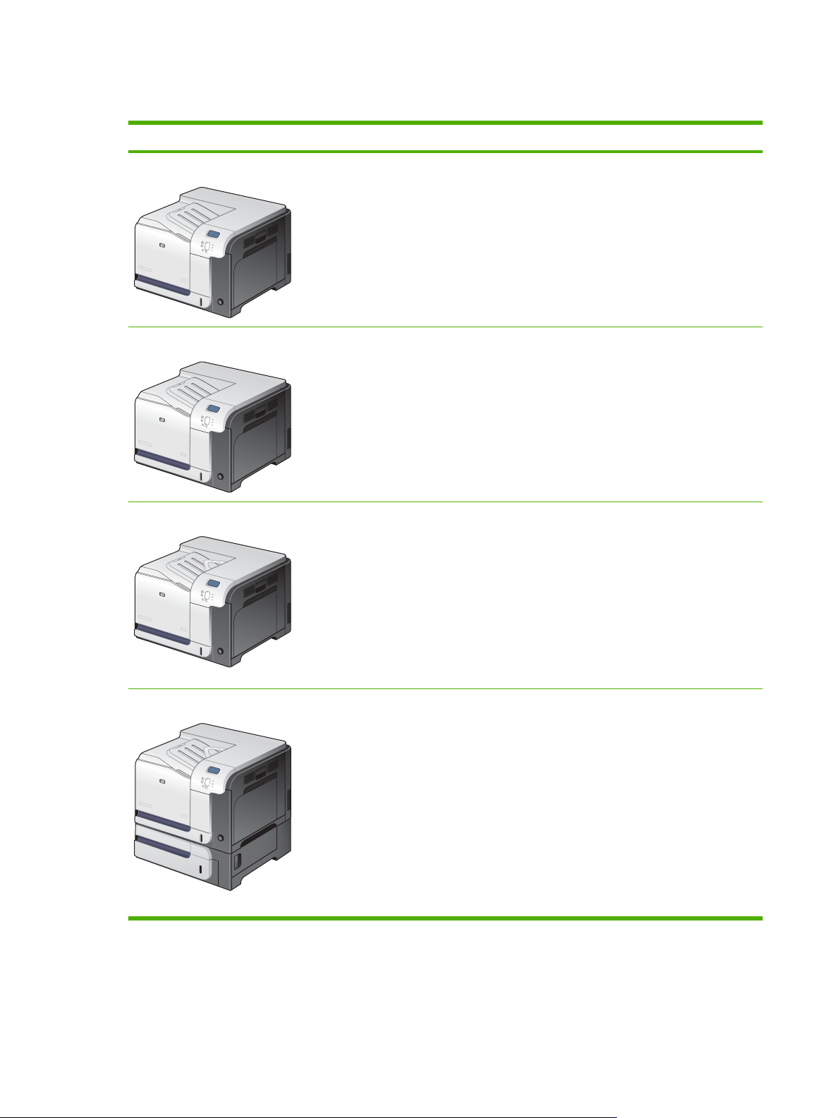
Product comparison
Model Features
HP Color LaserJet CP3525
HP Color LaserJet CP3525n
HP Color LaserJet CP3525dn
100-sheet multipurpose input tray (Tray 1)
●
250-sheet input tray (Tray 2)
●
250-sheet, face-down output bin
●
Hi-speed USB 2.0 port
●
256 megabytes (MB) of random access memory (RAM)
●
100-sheet multipurpose input tray (Tray 1)
●
250-sheet input tray (Tray 2)
●
250-sheet, face-down output bin
●
Hi-speed USB 2.0 port
●
HP Jetdirect embedded print server for connecting to a 10/100Base-TX network
●
256 megabytes (MB) of random access memory (RAM)
●
100-sheet multipurpose input tray (Tray 1)
●
250-sheet input tray (Tray 2)
●
250-sheet, face-down output bin
●
HP Color LaserJet CP3525x
Hi-speed USB 2.0 port
●
HP Jetdirect embedded print server for connecting to a 10/100Base-TX network
●
384 megabytes (MB) of random access memory (RAM)
●
Automatic two-sided printing
●
100-sheet multipurpose input tray (Tray 1)
●
250-sheet input tray (Tray 2)
●
250-sheet, face-down output bin
●
500-sheet paper and heavy media tray (Tray 3), including HP postcard media insert
●
for 101.6 x 152.4 mm (4 x 6 in) paper
Hi-speed USB 2.0 port
●
HP Jetdirect embedded print server for connecting to a 10/100Base-TX network
●
512 megabytes (MB) of random access memory (RAM)
●
Automatic two-sided printing
●
2 Chapter 1 Product basics ENWW
Page 31

Product features
Speed and throughput
Resolution
Memory
Prints up to 30 pages per minute (ppm) on letter-size paper and 30 ppm on A4-size
●
paper
As quick as 12 seconds to print the first page
●
Recommended maximum monthly print volume of 5,000 pages
●
A 515 megahertz (MHz) microprocessor
●
600 dots per inch (dpi) with Image Resolution Enhancement technology 3600 for
●
optimum overall imaging
1200 x 600 dpi for detailed line work and small text
●
HP Color LaserJet CP3525 and HP Color LaserJet CP3525n: 256 MB and of
●
random-access memory (RAM), expandable to 1 gigabyte (GB) by adding into the
open DIMM slot 200-pin small outline dual inline memory modules (DDR2
SODIMM) that support 128 MB, 256 MB, 512 MB, or 1 GB of RAM.
NOTE: If you install a 1 GB DIMM in the open slot, the total amount of memory
available is 1 GB.
HP Color LaserJet CP3525dn: 384 MB of random-access memory (RAM),
●
expandable to 1 gigabyte (GB) by replacing the original DIMM with 200-pin small
outline dual inline memory modules (DDR2 SODIMM) that support 128 MB, 256 MB,
512 MB, or 1 GB of RAM.
NOTE: If you install a 1 GB DIMM, the total amount of memory available is 1 GB.
For the HP Color LaserJet CP3525dn model, you must replace the original 128 MB
DIMM with a 1 GB DIMM to increase memory to 1 GB.
User interface
Paper handling
HP Color LaserJet CP3525x: 512 MB of random-access memory (RAM),
●
expandable to 1 gigabyte (GB) by replacing the original DIMM with 200-pin small
outline dual inline memory modules (DDR2 SODIMM) that support 128 MB, 256 MB,
512 MB, or 1 GB of RAM.
NOTE: If you install a 1 GB DIMM, the total amount of memory available is 1 GB.
For the HP Color LaserJet CP3525x model, you must replace one of the original
256 MB DIMMs with a 1 GB DIMM to increase memory to 1 GB.
Memory Enhancement technology (MEt) automatically compresses data to use
●
RAM more efficiently.
Four-line color graphical display on the control panel
●
An embedded Web server to gain access to support and order supplies (for
●
network-connected products)
HP Easy Printer Care software (a Web-based status and troubleshooting tool)
●
Internet-enabled supply-ordering capabilities through HP Easy Printer Care
●
software and embedded Web server
Tray 1 (multipurpose tray): A multipurpose tray for paper, transparencies, labels,
●
envelopes, and other paper types. The tray holds up to 100 sheets of paper, 50
transparencies, or 10 envelopes
Tray 2: 250-sheet tray.
●
Optional Tray 3: 500-sheet paper and heavy media tray, and an optional
●
HP Postcard media insert. (Both are included with the HP Color LaserJet CP3525x
printer.) Holds standard and custom-size paper. This tray automatically detects
common paper sizes.
ENWW Product features 3
Page 32

Two-sided printing: The HP Color LaserJet CP3525dn printer and HP Color
●
LaserJet CP3525x printer support automatic two-sided printing. The other models
support manual two-sided printing.
Standard output bin: The standard output bin is located on the top of the product.
●
This bin can hold up to 250 sheets of paper. The product has a sensor that indicates
when the bin is full.
Languages and fonts
Print cartridges
For information about supported paper sizes, see
Supported paper and print media sizes
on page 44.
For information about supported paper types, see
Supported paper and print media types
on page 47.
HP Printer Control Language PCL 5, PCL 6, and HP postscript level 3 emulation
●
Direct PDF
●
80 scalable TrueType PS typefaces
●
For information regarding print cartridges, see
●
www.hp.com/go/
learnaboutsupplies.
Authentic HP print cartridge detection
●
Automatic toner strip remover
●
This product uses the following consumable supplies:
●
Standard black print cartridge: CE250A
◦
High-capacity black print cartridge: CE250X
◦
Cyan print cartridge: CE251A
◦
Yellow print cartridge: CE252A
◦
Magenta print cartridge: CE253A
◦
Supported operating systems
Connectivity
Environment
Toner collection unit: CE254A
◦
®
Microsoft
●
2003, and Windows
Macintosh OS X V10.3.9, V10.4, V10.5, and later
●
Novell NetWare
●
Unix
●
Linux
●
USB 2.0 connection
●
Host USB 2.0-like port for third-party connection
●
Local area network (LAN) connector (RJ-45) for the embedded HP Jetdirect print
●
Windows® 2000, Windows® XP, Windows Vista™, Windows® Server
®
®
Server 2008
server (not included with the HP Color LaserJet CP3525 printer)
One enhanced input/output (EIO) slot
●
Sleep setting saves energy
●
High content of recyclable components and materials
●
Instant-on fuser saves energy
●
4 Chapter 1 Product basics ENWW
Page 33

Security
Secure Disk Erase
●
Security lock (optional)
●
Job retention
●
User PIN authentication for stored jobs
●
IPsec security
●
HP encrypted High Performance EIO hard drive (optional)
●
Self-help
Show-me-how pages that you can print from the control panel
●
Job aids for specific tasks available from
●
Animations and help on the control panel
●
Animations on the CD
●
www.hp.com/support/cljcp3525.
ENWW Product features 5
Page 34

Product view
Front view
1 Output-bin extension
2 Standard output bin
3 Duplex switchback guide (HP Color LaserJet CP3525dn printer and HP Color LaserJet CP3525x printer only)
4 Control panel
5 Right door (access for clearing jams)
6 Tray 1 (pull the handle to open the tray)
7 Power button (illuminates when turned on)
8 Lower-right door (access for clearing jams)
9 Tray 2
10 Optional Tray 3 (included with the HP Color LaserJet CP3525x printer)
11 Front door (access to print cartridges and toner collection unit)
6 Chapter 1 Product basics ENWW
Page 35

Back view
1
1 Slot for a cable-type security lock
2 Interface ports
3 Power connection
2
3
ENWW Product view 7
Page 36

Interface ports
1 EIO interface expansion slot
2 RJ-45 network port (not activated with the HP Color LaserJet CP3525 printer)
3 Hi-speed USB 2.0 printing port
1
2
3
Serial number and model number location
The model number and serial number are listed on an identification label located on the back of the
product. The serial number contains information about the country/region of origin, the product version,
production code, and the production number of the product.
Model name Model number
HP Color LaserJet CP3525 CC468A
HP Color LaserJet CP3525n CC469A
HP Color LaserJet CP3525dn CC470A
HP Color LaserJet CP3525x CC471A
8 Chapter 1 Product basics ENWW
Page 37

2 Control panel
Use the control panel
●
Control panel menus
●
Menu hierarchy
●
Show Me How menu
●
Retrieve job menu
●
Information menu
●
Paper handling menu
●
Configure device menu
●
Diagnostics menu
●
Service menu
●
ENWW 9
Page 38

Use the control panel
The control panel has a color, graphical and text display that provides access to all product functions.
Use the buttons to control jobs and the product status. The lights indicate overall product status.
Control-panel layout
The control panel includes a color, graphical and text display, job-control buttons, and three light-emitting
diode (LED) status lights.
1
2 3
4
5
11
6
10
89
1 Control panel display Shows status information, menus, help information, and error messages.
2 Up arrow button Navigates menus and text, and increases the values of numerical items in
3 OK button Makes selections, resumes printing after continuable errors, and overrides
4 Ready light The Ready light indicates that the product is ready to begin processing any
7
the display.
a non-HP print cartridge.
job.
5 Data light The Data light indicates that the product is receiving data.
6 Attention light The Attention light indicates that the product has a condition that requires
intervention. Examples include an empty paper tray or an error message
on the display.
7 Down arrow button Navigates menus and text, and decreases the values of numerical items in
the display.
8
9
10
11 Help button Provides detailed information, including animations, about product
Menu button
Back arrow button
Stop button
Opens and closes menus.
Navigates backward in nested menus.
Halts the current job, presents a choice to resume or cancel the current job,
clears paper from the product, and clears any continuable errors that are
associated with the halted job. If the product is not printing a job, pressing
Stop pauses the product.
messages or menus.
10 Chapter 2 Control panel ENWW
Page 39

Interpreting control panel indicator lights
Indicator On Off Flashing
Ready
(green)
Data
(green)
Attention
(amber)
Product is online (able to
accept and process data).
Processed data is present in
the product, but more data is
needed to complete the job.
A critical error has occurred.
Product requires attention.
Product is offline or is turned
off.
Product is not processing or
receiving data.
No conditions exist that
require attention.
Product is attempting to stop
printing and go offline.
Product is processing and
receiving data.
An error has occurred.
Product requires attention.
ENWW Use the control panel 11
Page 40

Control panel menus
You can perform most routine printing tasks from the computer through the printer driver or software
application. This is the most convenient way to control the product, and will override the product controlpanel settings.
You can also control the product by changing settings in the product’s control panel. Use the control
panel to access features not supported by the printer driver or software application, and to configure
trays for paper size and type.
Use the menus
●
Enter and exit the menus by pressing the Menu button
Select a menu item by using the OK button as well as select numerical values when configuring
●
the product.
Use the up or down arrows
●
up and down arrows can increase and decrease numerical value selections. Hold down the up or
down arrows to scroll faster.
The back button
●
If no key is pressed for 60 seconds, the product exits the menus.
●
allows you to move back in menu selections.
to navigate through the menus. In addition to menu navigation, the
.
12 Chapter 2 Control panel ENWW
Page 41

Menu hierarchy
The following top-level menus are available:
SHOW ME HOW. See
●
RETRIEVE JOB. See
●
INFORMATION. See
●
PAPER HANDLING. See
●
CONFIGURE DEVICE. See
●
DIAGNOSTICS. See
●
SERVICE. See
●
Service menu on page 42 for more information.
Show Me How menu on page 14 for more information.
Retrieve job menu on page 15 for more information.
Information menu on page 17 for more information.
Paper handling menu on page 18 for more information.
Configure device menu on page 19 for more information.
Diagnostics menu on page 40 for more information.
ENWW Menu hierarchy 13
Page 42

Show Me How menu
The SHOW ME HOW menu prints pages that provide more information about the product.
To display: Press the Menu button
Item Explanation
CLEAR JAMS Provides instructions for clearing jams on the product.
LOAD TRAYS Provides instructions for loading and configuring trays.
LOAD SPECIAL MEDIA Provides instructions for loading special print media such as envelopes,
PRINT BOTH SIDES Provides instructions for printing on both sides of the paper (duplex printing).
SUPPORTED PAPER Provides a list of the supported paper and print media.
PRINT HELP GUIDE Prints a page that shows links to additional help on the Web.
, and then select the SHOW ME HOW menu.
transparencies, and labels.
14 Chapter 2 Control panel ENWW
Page 43

Retrieve job menu
The RETRIEVE JOB menu allows you to view listings of all stored jobs.
To display: Press the Menu button
, and then select the RETRIEVE JOB menu.
NOTE: Values that have an asterisk (*) are the factory-default values. Some menu items have no
default.
Item Sub-item Options Description
<USER NAME> Each user who has stored jobs is
listed by name. Select the
appropriate user name to see a list of
stored jobs.
ALL JOBS (NO PIN) PRINT
PRINT AND DELETE
DELETE
ALL JOBS (WITH
PIN)
PRINT
PRINT AND DELETE
DELETE
This message is displayed if a user
has two or more stored jobs that do
not require a PIN.
Either the PRINT option or the PRINT
AND DELETE option displays,
depending on the type of jobs listed.
Use the COPIES option to specify he
number of copies of the job to be
printed.
This message is displayed if a user
has two or more stored jobs that
require a PIN.
Either the PRINT option or the PRINT
AND DELETE option displays,
depending on the type of jobs listed.
Use the COPIES option to specify he
number of copies of the job to be
printed.
<JOB NAME X> PRINT
PRINT AND DELETE
DELETE
COPIES Specifies the number of copies of the
Each job is listed by name.
Either the PRINT option or the PRINT
AND DELETE option displays,
depending on the type of jobs listed.
Use the COPIES option to specify the
number of copies of the job to be
printed.
job to be printed. The default is 1.
If you select the JOB option, the
number of copies specified in the
driver are printed.
If you select the CUSTOM menu,
another setting displays where you
can specify the number of copies of
the job to be printed. The number of
copies that were specified in the
driver are multiplied by the number of
copies specified on the control panel.
For example, if you specified two
ENWW Retrieve job menu 15
Page 44

Item Sub-item Options Description
copies in the driver and specify two
copies on the control panel, a total of
four copies of the job are printed.
16 Chapter 2 Control panel ENWW
Page 45

Information menu
Use the INFORMATION menu to access and print specific product information.
To display: Press the Menu button
Item Description
PRINT MENU MAP Prints the control-panel menu map, which shows the layout and current
PRINT CONFIGURATION Prints the product configuration pages, which show the printer settings and
PRINT SUPPLIES STATUS PAGE Prints the approximate remaining life for the supplies; reports statistics on
SUPPLIES STATUS Displays the approximate status of the print cartridges, fuser kit, and toner-
PRINT USAGE PAGE Prints a count of all paper sizes that have passed through the product; lists
PRINT COLOR USAGE JOB LOG Prints the color-use statistics for the printer.
PRINT DEMO Prints a demonstration page.
, and then select the INFORMATION menu.
settings of the control-panel menu items.
installed accessories.
total number of pages and jobs processed, serial number, page counts, and
maintenance information.
HP provides approximations of the remaining life for the supplies as a
customer convenience. The actual remaining supply levels might be different
than the approximations provided.
collection unit in a scrollable list. For each item, press the OK button to open
help for the item.
whether they were simplex, duplex, monochrome, or color; and reports the
page count.
PRINT RGB SAMPLES Prints color samples for different RGB values. Use the samples as a guide
PRINT CMYK SAMPLES Prints color samples for different CMYK values. Use the samples as a guide
PRINT FILE DIRECTORY Prints the name and directory of files stored in the product.
PRINT PCL FONT LIST Prints the available PCL fonts.
PRINT PS FONT LIST Prints the available PS fonts.
for matching printed colors.
for matching printed colors.
ENWW Information menu 17
Page 46

Paper handling menu
Use this menu to configure input trays by size and type. It is important to correctly configure the trays
with this menu before you print for the first time.
To display: Press the Menu button
, and then select the PAPER HANDLING menu.
NOTE: If you have used other HP LaserJet product models, you might be accustomed to configuring
Tray 1 to First mode or Cassette mode. On HP Color LaserJet CP3525 Series printers, setting Tray 1
to ANY SIZE and ANY TYPE is equivalent to First mode. Setting Tray 1 to a setting other than ANY
SIZE or ANY TYPE is equivalent to Cassette mode.
Menu item Value Description
TRAY 1 SIZE A list of available sizes appears. Allows you to configure the paper size for
Tray 1. The default is ANY SIZE. See
Supported paper and print media sizes
on page 44 for a complete list of available
sizes.
TRAY 1 TYPE A list of available types appears. Allows you to configure the paper type for
TRAY <X> SIZE
X = 2 or optional 3
A list of available sizes appears. Allows you to configure the paper size for
Tray 1. The default is ANY TYPE. See
Supported paper and print media types
on page 47 for a complete list of available
types.
Tray 2 or optional Tray 3. The default size
is LETTER or A4, depending on your
country/region. Tray 2 does not detect the
paper size by the guides in the tray. Tray 3
detects some paper sizes by the guides in
the tray. See
media sizes on page 44 for a complete list
of available sizes.
Supported paper and print
TRAY <X> TYPE
X = 2 or optional 3
A list of available types appears. Allows you to configure the paper type for
Tray 2 or optional Tray 3. The default is
PLAIN. See
media types on page 47 for a complete list
of available types.
Supported paper and print
18 Chapter 2 Control panel ENWW
Page 47

Configure device menu
The CONFIGURE DEVICE menu allows you to change the default printing settings, adjust the print
quality, change the system configuration and I/O options, and reset the default settings.
Printing menu
These settings affect only jobs without identified properties. Most jobs identify all of the properties and
override the values set from this menu.
To display: Press the Menu button
, select the CONFIGURE DEVICE menu, and then select the
PRINTING menu.
NOTE: Values that have an asterisk (*) are the factory-default values. Some menu items have no
default.
Menu item Values Description
COPIES Range: 1 - 32000 Allows you to set the default number of
DEFAULT PAPER SIZE A list of available sizes appears. Allows you to set the default paper size.
DEFAULT CUSTOM PAPER SIZE
DUPLEX OFF*
DUPLEX BINDING LONG EDGE*
UNIT OF MEASURE
●
X DIMENSION
●
Y DIMENSION
●
ON
SHORT EDGE
copies for print jobs. The default number is
1.
Allows you to set the default size for any
custom print job. The default unit of
measure is MILLIMETERS.
Allows you to enable or disable two-sided
printing.
NOTE: This menu is available only on the
HP Color LaserJet CP3525dn printer and
the HP Color LaserJet CP3525x printer
Allows you to change the binding edge for
two-sided printing.
NOTE: This menu is available only on the
HP Color LaserJet CP3525dn printer and
the HP Color LaserJet CP3525x printer
OVERRIDE A4/LETTER NO
YES*
MANUAL FEED OFF*
ON
COURIER FONT REGULAR*
DARK
WIDE A4 NO *
YES
Allows you to set the product to print an A4
job on letter-size paper when no A4 paper
is loaded.
Setting this option to ON makes MANUAL
FEED the default for jobs that do not select
a tray.
Allows you to select a version of the Courier
font.
The DARK setting is an internal Courier
font available on HP LaserJet Series III
printers and older.
Allows you to change the printable area of
A4 paper. If you select NO, the printable
area is seventy-eight 10-pitch characters
on a single line. If you select YES, the
ENWW Configure device menu 19
Page 48

Menu item Values Description
printable area is eighty 10-pitch characters
on a single line.
PRINT PS ERRORS OFF*
PRINT PDF ERRORS OFF*
PCL sub-menu
This menu configures settings for the printer control language.
To display: Press the Menu button
menu, and then select the PCL menu.
NOTE: Values that have an asterisk (*) are the factory-default values. Some menu items have no
default.
Item Values Description
FORM LENGTH Sets vertical spacing from 5 to 128 lines for default paper
ORIENTATION PORTRAIT*
Allows you to select to print PS error pages.
ON
Allows you to select to print PDF error
pages.
ON
, select the CONFIGURE DEVICE menu, select the PRINTING
size. The default is 60.
Allows you to set the default page orientation to portrait or
landscape.
LANDSCAPE
FONT SOURCE A list of available font sources
displays.
FONT NUMBER The product assigns a number to each font and lists the
FONT PITCH Selects the font pitch. This item might not appear, depending
FONT POINT SIZE Selects the font point size. The range is 4.00 to 999.75. The
SYMBOL SET A list of available symbol sets
displays.
APPEND CR TO LF NO*
YES
SUPPRESS BLANK PAGES NO*
YES
Selects the font source. The default is INTERNAL.
numbers on the PCL font list. The range is 0 to 102. The
default is 0.
on the font selected. The range is 0.44 to 99.99. The default
is 10.00.
default is 12.00.
Selects any one of several available symbol sets at the
product control panel. A symbol set is a unique grouping of
all the characters in a font. PC-8 or PC-850 is recommended
for line-draw characters. The default is PC-8.
Select YES to append a carriage return to each line-feed that
is encountered in backward-compatible PCL jobs (pure text,
no job control). Some environments indicate a new line by
only the line-feed control code. Use this option to append the
required carriage return to each line feed.
When generating your own PCL, extra form feeds are
included that would cause a blank page to be printed. Select
YES for form feeds to be ignored if the page is blank.
20 Chapter 2 Control panel ENWW
Page 49

Item Values Description
MEDIA SOURCE MAPPING The PCL5 MEDIA SOURCE MAPPING command selects an
input tray by a number that maps to the various available
trays and feeders.
STANDARD* The numbering is based on newer HP LaserJet printers with
updated changes to the numbering of trays and feeders.
CLASSIC The numbering is based on HP LaserJet 4 printers and earlier
models.
ENWW Configure device menu 21
Page 50

Print Quality menu
To display: Press the Menu button , select the CONFIGURE DEVICE menu, and then select the
PRINT QUALITY menu.
NOTE: Values that have an asterisk (*) are the factory-default values. Some menu items have no
default.
Item Sub-item Values Description
ADJUST COLOR HIGHLIGHTS
CYAN DENSITY
●
MAGENTA DENSITY
●
YELLOW DENSITY
●
BLACK DENSITY
●
MIDTONES
CYAN DENSITY
●
MAGENTA DENSITY
●
YELLOW DENSITY
●
BLACK DENSITY
●
SHADOWS
CYAN DENSITY
●
MAGENTA DENSITY
●
YELLOW DENSITY
●
BLACK DENSITY
●
RESTORE COLOR VALUES Restore the color settings by resetting the density
Range from +5 to –5.
Default is 0.
Range from +5 to –5.
Default is 0.
Range from +5 to –5.
Default is 0.
Adjust the darkness or lightness of highlights on a
printed page. Lower values represent lighter
highlights on a printed page, and higher values
represent darker highlights on a printed page.
Adjust the darkness or lightness of midtones on a
printed page. Lower values represent lighter
midtones on a printed page, and higher values
represent darker midtones on a printed page.
Adjust the darkness or lightness of shadows on a
printed page. Lower values represent lighter
shadows on a printed page, and higher values
represent darker shadows on a printed page.
values of each color.
SET REGISTRATION For each tray, setting the registration shifts the
ADJUST TRAY <X> Shift from -20 to 20
along the X or Y axes. 0
is the default.
PRINT TEST PAGE Print a test page for setting the registration.
X1 SHIFT
Y1 SHIFT
X2 SHIFT
Y2 SHIFT
margin alignment to center the image on the page
from top to bottom and from left to right. You can
also align the image on the front with the image
printed on the back.
Perform the alignment procedure for each tray.
When it creates an image, the product scans
across the page from side to side as the sheet
feeds from top to bottom into the product.
The scan direction is referred to as X. X1 is the
scan direction for a single-sided page or for the first
side of a two-sided page. X2 is the scan direction
for the second side of a two-sided page.
The feed direction is referred to as Y. Y1 is the feed
direction for a single-sided page or for the first side
of a two-sided page. Y2 is the feed direction for the
second side of a two-sided page.
22 Chapter 2 Control panel ENWW
Page 51

Item Sub-item Values Description
AUTO SENSE MODE TRAY 1 SENSING FULL SENSING
(default)
TRANSPARENCY
ONLY
ADJUST PAPER TYPES A list of paper types displays. A list of print modes
displays.
RESTORE MODES Use this feature to return all paper type-mode
OPTIMIZE A list of available options
QUICK CALIBRATE
NOW
FULL CALIBRATE NOW Performs all product calibrations.
DELAY CALIBRATION
AT WAKE/POWER-ON
displays.
RESTORE OPTIMIZE Use this feature to return all the settings in the
Performs a partial product calibration.
NO
Allows you to optimize various print modes to
YES*
Sets the sensing option for Tray 1 for paper types
using AUTO SENSE mode.
When FULL SENSING is selected, the product
senses every page and switches modes
accordingly. The product can distinguish
transparencies from other paper types.
When TRANSPARENCY ONLY is selected, the
product senses only the first page. The product
can distinguish transparencies from other paper
types.
Configure the print mode that is associated with
each media type.
settings to the factory-default settings.
address print quality issues.
OPTIMIZE menu to the factory-default values.
This menu controls the timing of the calibration
when the product wakes up or is turned on.
Select NO to have the product calibrate
●
immediately when it wakes up or is turned on.
The product will not print any jobs until it
finishes calibrating.
RESOLUTION Image REt 3600*
1200x600 dpi
EDGE CONTROL OFF
LIGHT
NORMAL*
MAXIMUM
Select YES to enable a product that is asleep
●
to accept print jobs before it calibrates. It may
start calibrating before it has printed all the
jobs it has received. This option allows
quicker printing when coming out of sleep
mode or when you turn the product on, but
print quality might be reduced.
NOTE: For best results, allow the product to
calibrate before printing. Print jobs performed
before calibration might not be of the highest
quality.
Sets the resolution at which the product prints. The
default value is Image REt 3600. Try the
1200x600 dpi setting to improve printing for
detailed line work or small text.
The Edge Control setting determines how edges
are rendered. Edge control has two components:
adaptive halftoning and trapping. Adaptive
halftoning increases edge sharpness. Trapping
ENWW Configure device menu 23
Page 52

Item Sub-item Values Description
reduces the effect of color-plane misregistration by
overlapping the edges of adjacent objects slightly.
OFF turns off both trapping and adaptive
●
halftoning.
LIGHT sets trapping at a minimal level, and
●
adaptive halftoning is on.
NORMAL is the default trapping setting.
●
Trapping is at a medium level and adaptive
halftoning is on.
MAXIMUM is the most aggressive trapping
●
setting. Adaptive halftoning is on.
AUTO CLEANING OFF*
ON
CLEANING INTERVAL 500*
1000
2000
5000
10000
20000
AUTO CLEANING SIZE LETTER*
A4
CREATE CLEANING
PAGE
PROCESS CLEANING
PAGE
Prints a page of instructions for cleaning excess
Allows you to create and process a cleaning page
When auto-cleaning is on, the product prints a
cleaning page when the page count reaches the
CLEANING INTERVAL setting.
When AUTO CLEANING is on, this option
specifies the number of pages that are printed
before a cleaning page is automatically printed.
When AUTO CLEANING is on, this option
specifies the paper size that is used to print the
cleaning page.
toner off the pressure roller in the fuser.
NOTE: This option is available only for the HP
Color LaserJet CP3525 printer and the HP Color
LaserJet CP3525n printer.
for cleaning the pressure roller in the fuser. When
the cleaning process runs, a cleaning page is
printed. This page can be discarded.
NOTE: For the HP Color LaserJet CP3525
printer and the HP Color LaserJet CP3525n
printer, you must first select the CREATE
CLEANING PAGE option.
24 Chapter 2 Control panel ENWW
Page 53

System setup menu
Use the SYSTEM SETUP menu to change product- configuration defaults such as sleep mode, product
personality (language), and jam recovery.
To display: Press the Menu button
, select the CONFIGURE DEVICE menu, and then select the
SYSTEM SETUP menu.
NOTE: Values that have an asterisk (*) are the factory-default values. Some menu items have no
default.
Item Sub-item Values Description
DATE/TIME DATE - - - - /[MMM]/[DD] YEAR =
[YYYY]/- - - /[DD] MONTH=
[YYYY]/[MMM]/- - DAY=
DATE FORMAT YYYY/MMM/DD*
MMM/DD/YYYY
DD/MMM/YYYY
TIME - - :[MM] [PM] HOUR =
[HH]: - - [PM] MINUTE=
[HH]:[MM] - - AM/PM=
TIME FORMAT 12 HOUR*
24 HOUR
Allows you to set the correct date.
The range for the year is 2008 to
2037.
Allows you to choose the order in
which the year, month, and day
appear in the date.
Allows you to select from various
configurations for the TIME format.
Different wizards appear
depending on the TIME FORMAT
selected.
Allows you to select 12 HOUR or
24 HOUR format.
JOB STORAGE LIMIT Continuous value
Range: 1–100
Default = 32
JOB HELD TIMEOUT OFF*
1 HOUR
4 HOURS
1 DAY
1 WEEK
SHOW ADDRESS AUTO
OFF*
RESTRICT COLOR USE ENABLE COLOR*
COLOR IF ALLOWED
DISABLE COLOR
Allows you to specify the number
of Quick Copy jobs that can be
stored on the product. The default
value is 32. The maximum allowed
value is 100.
Allows you to set the amount of
time that Quick Copy jobs are kept
before being automatically deleted
from the queue. This menu item
only appears when a hard disk is
installed.
This item determines whether the
product’s IP address is shown on
the display with the Ready
message.
Disables or restricts color use.
To use the COLOR IF ALLOWED
setting, set up user permissions
through the embedded Web
server, HP Easy Printer Care, or
Web Jetadmin.
ENWW Configure device menu 25
Page 54

Item Sub-item Values Description
COLOR/BLACK MIX AUTO*
MOSTLY COLOR PAGES
MOSTLY BLACK PAGES
TRAY BEHAVIOR Use this menu to control how the
USE REQUESTED TRAY EXCLUSIVELY*
FIRST
This menu item establishes how
the product switches from color to
monochrome (black and white)
mode for maximum performance
and for extending print cartridge
life.
AUTO resets the product to the
factory default setting.
Select MOSTLY COLOR PAGES
if nearly all of your print jobs are
color with high page coverage.
Select MOSTLY BLACK PAGES if
you print mostly monochrome print
jobs, or a combination of color and
monochrome print jobs.
product handles paper trays and
related prompts at the control
panel.
USE REQUESTED TRAY handles
jobs that have specified a specific
input tray. Two options are
available:
EXCLUSIVELY: The product
●
never selects a different tray
when the user has indicated
that a specific tray should be
used, even if that tray is
empty.
MANUALLY FEED PROMPT ALWAYS*
UNLESS LOADED
FIRST: The product can pull
●
from another tray if the
specified tray is empty, even
though the user specifically
indicated a tray for the job.
This option controls whether a
manual feed message should
appear when the type or size for a
job does not match the size or type
configured for Tray 1. Two options
are available:
ALWAYS: A prompt always
●
appears before printing a
manual-feed job.
UNLESS LOADED: A
●
message appears only if the
multipurpose tray is empty or
does not match the size or
type of the job.
26 Chapter 2 Control panel ENWW
Page 55

Item Sub-item Values Description
PS DEFER MEDIA ENABLED*
DISABLED
SIZE/TYPE PROMPT DISPLAY*
DO NOT DISPLAY
USE ANOTHER TRAY ENABLED*
DISABLED
This option affects how paper is
handled when printing from an
Adobe PS print driver.
ENABLED uses HP’s paper-
●
handling model.
DISABLED uses the Adobe
●
PS paper-handling model.
This option controls whether the
tray configuration message
appears whenever a tray is closed.
Two options are available:
DISPLAY: This option shows
●
the tray configuration
message when a tray is
closed. You can configure the
tray size or type directly from
this message.
DO NOT DISPLAY: This
●
option prevents the tray
configuration message from
automatically appearing.
This option turns on or off the
control-panel prompt to select
another tray when the specified
tray is empty. Two options are
available:
ALTERNATIVE
LETTERHEAD MODE
DUPLEX BLANK PAGES AUTO*
ON
OFF*
YES
ENABLED: When this option
●
is selected, the user is
prompted either to add paper
to the selected tray or to
choose a different tray.
DISABLED: When this option
●
is selected, the user is not
given the option of selecting a
different tray. The product
prompts the user to add paper
to the tray that was initially
selected.
This option allows you to load
letterhead or preprinted paper the
same way for every job, whether
printing on one or both sides of the
page. For more information, see
Paper orientation for loading trays
on page 50.
This option controls how the
product handles two-sided jobs
ENWW Configure device menu 27
Page 56

Item Sub-item Values Description
(duplexing). Two options are
available:
AUTO enables Smart
●
Duplexing, which instructs
the product not to process
both sides if the second side
is blank. This can improve
print speed.
YES disables Smart
●
Duplexing and forces the
duplexer to flip the sheet of
paper even if it is printed on
only one side.
NOTE: This option is available
only for the HP Color LaserJet
CP3525dn printer or the HP Color
LaserJet CP3525x printer.
SLEEP DELAY 1 MINUTE
15 MINUTES*
30 MINUTES
45 MINUTES
60 MINUTES
90 MINUTES
2 HOURS
4 HOURS
WAKE TIME <DAY OF THE WEEK> OFF*
CUSTOM
OPTIMUM SPEED/ENERGY
USAGE
FASTER FIRST PAGE*
SAVE ENERGY
Reduces power consumption
when the product has been
inactive for the selected period.
Allows you to configure the daily
wake time for the product to avoid
warm-up or calibration time. Select
a day of the week and then select
CUSTOM. Set the wake time for
that day, and then choose whether
the wake time should be applied to
all days of the week.
Controls the fuser cool down
behavior.
If FASTER FIRST PAGE is
selected, the fuser is not allowed to
cool down, and the first page
processes faster for any new job
that is sent to the printer.
If SAVE ENERGY is selected, the
fuser is allowed to cool down
naturally. The speed penalty on the
first page depends on how long the
fuser has been sitting idle.
DISPLAY BRIGHTNESS Range is –10 through 10. Sets the brightness of the control
panel display. The default is 0.
28 Chapter 2 Control panel ENWW
Page 57

Item Sub-item Values Description
PERSONALITY AUTO*
PCL
PDF
PS
CLEARABLE WARNINGS JOB*
ON
AUTO CONTINUE OFF
ON*
REPLACE SUPPLIES Sets the product behavior for when
Sets the default personality to
automatic switching, PCL, PDF, or
PS modes.
Sets whether a warning is cleared
on the control panel or when
another job is sent.
Determines product behavior
when the system generates an
Auto Continuable error.
a supply item is low.
The product displays an "Order
supplies" message when a supply
item is running low and a "Replace
supplies" message when a supply
item has reached its estimated end
of life. To ensure optimal print
quality, HP recommends replacing
a supply item when the "Replace
supplies" message is displayed.
The supply does not have to be
replaced at this point unless the
print quality is no longer
acceptable. Printing beyond this
point is possible using OVERRIDE
AT OUT 1 or OVERRIDE AT OUT
2. The Override options allow the
product to continue using a supply
item that has reached its estimated
end of life.
STOP AT LOW* Choose STOP AT LOW to stop
STOP AT OUT Choose STOP AT OUT to stop
OVERRIDE AT OUT 1
OVERRIDE AT OUT 2
printing when a supply reaches a
low condition.
printing when the estimated end of
life has been reached for a supply.
Printing beyond this point is
possible using OVERRIDE AT
OUT 1 or OVERRIDE AT OUT 2.
The supply does not need to be
replaced now unless the print
quality is no longer acceptable.
Choose OVERRIDE AT OUT 1 to
allow the product to continue
printing when supply items, other
than the toner collection unit, have
reached the end of their estimated
life. Using this option will
eventually result in unacceptable
print quality. Consider having a
replacement cartridge available for
when the print quality becomes
unacceptable.
ENWW Configure device menu 29
Page 58

Item Sub-item Values Description
Choose OVERRIDE AT OUT 2 to
allow the product to continue
printing when any color supply is
past the end of its estimated
capacity, including the toner
collection unit. This option is not
recommended because of the risk
of overfilling the toner collection
unit, which could result in the need
to service your printer.
Information about the remaining
toner is not available when printing
in Override mode.
Once an HP supply has reached
the end of its estimated life, HP's
Premium Protection Warranty on
that supply has ended. For
Warranty information, see
HP's Premium Protection
Warranty: LaserJet print cartridge
limited warranty statement
on page 509.
The Override options can be
enabled or disabled at any time,
and do not have to be re-enabled
for each supply item. The product
automatically continues printing
when a supply item reaches the
end of its estimated life. The
message “Replace supply
Override in use” displays on the
control panel while a supply is used
in Override mode. When the
supply item is replaced with a new
supply, Override is de-activated
until another supply item reaches
the end of its estimated life.
PAGE LIMIT
Range of 0 to 100000
SUPPLY INFORMATION PAGES REMAINING
ORDER MESSAGES
LEVEL GAUGE
ORDER AT RANGE=0-100% The user can set the supply
ON*
OFF
This menu displays if you select
YES, USE OVERRIDE for either
Override option. Select the number
of pages the product continues to
print while in override mode. The
default is 1500.
When PAGES REMAINING is set
to OFF, the pages remaining
portion of the supplies message is
suppressed.
When ORDER MESSAGES is set
to OFF, the supplies order
message is not displayed.
When LEVEL GAUGE is set to
OFF, the supplies gauge is not
displayed.
percentage remaining at which the
“Order” message appears.
30 Chapter 2 Control panel ENWW
Page 59

Item Sub-item Values Description
The default depends on which
black print cartridge is installed. If
the standard-capacity black print
cartridge is installed, the default is
8%. If the high-capacity black print
cartridge is installed, the default is
7%.
COLOR SUPPLY OUT STOP*
AUTOCONTINUE BLACK
JAM RECOVERY AUTO*
OFF
ON
RAM DISK AUTO*
OFF
Sets the product behavior when a
color supply has reached its
estimated end of life.
When the product is set to STOP,
the REPLACE <COLOR>
CARTRIDGE or REPLACE
SUPPLIES message is displayed
when one or more color supplies
reach the out condition.
When the product is set to
AUTOCONTINUE BLACK, the
product continues printing with
black toner only.
Sets whether the product will
attempt to reprint pages after a
jam. If you select AUTO, the
product reprints pages if enough
memory is available for full-speed
two-sided printing.
Sets how the RAM disk feature is
configured. This is only available if
there is no hard disk installed and
the printer has at least 8 MB of
memory.
If the AUTO setting is enabled, the
product determines the optimal
RAM disk size based on the
amount of available memory.
If the OFF setting is enabled, the
RAM disk is disabled, but a
minimal RAM disk is still active.
LANGUAGE A listing of available languages
appears.
Sets the default language. The
default language is ENGLISH.
ENWW Configure device menu 31
Page 60

I/O menu
Items on the I/O (input/output) menu affect the communication between the product and the computer.
If the product contains an HP Jetdirect print server, you can configure basic networking parameters by
using this submenu. You can also configure these and other parameters through HP Web Jetadmin or
the embedded Web server.
To display: Press the Menu button
, select the CONFIGURE DEVICE menu, and then select the I/
O menu.
NOTE: Values that have an asterisk (*) are the factory-default values. Some menu items have no
default.
Item Sub-item Values Description
I/O TIMEOUT Range: 5 - 300 Allows you to set the product I/O
EMBEDDED JETDIRECT MENU See the next table for a list of options.
Table 2-1 Embedded Jetdirect and EIO <X> Jetdirect menus
Item Sub-item Sub-item Values Description
INFORMATION PRINT
PROTOCOLS
YES
NO*
Use this item to print a page that lists the
configuration of the following protocols: IPX/
SPX, Novell NetWare, AppleTalk, DLC/LLC.
TIMEOUT in seconds. The default
is 15 seconds.
Use this setting to adjust timeout
for the best performance. If data
from other ports appears in the
middle of your print job, increase
the timeout value.
PRINT SEC PAGE YES*
NO
TCP/IP ENABLE ON*
OFF
HOST NAME An alphanumeric string, up to 32 characters,
IPV4 SETTINGS CONFIG METHOD BOOTP
DHCP
AUTO IP
MANUAL
YES: Prints a page that contains the current
security settings on the HP Jetdirect print
server.
NO: A security settings page is not printed.
ON: Enable the TCP/IP protocol.
OFF: Disable the TCP/IP protocol.
used to identify the product. This name is
listed on the HP Jetdirect configuration page.
The default host name is NPIxxxxxx, where
xxxxxx is the last six digits of the LAN
hardware (MAC) address.
Specifies the method that TCP/IPv4
parameters will be configured on the
HP Jetdirect print server.
Use BOOTP (Bootstrap Protocol) for
automatic configuration from a BootP server.
Use DHCP (Dynamic Host Configuration
Protocol) for automatic configuration from a
DHCPv4 server. If selected and a DHCP
32 Chapter 2 Control panel ENWW
Page 61

Table 2-1 Embedded Jetdirect and EIO <X> Jetdirect menus (continued)
Item Sub-item Sub-item Values Description
lease exists, DHCP RELEASE and DHCP
RENEW menus are available to set DHCP
lease options.
Use AUTO IP for automatic link-local IPv4
addressing. An address in the form
169.254.x.x is assigned automatically.
If you set this option to MANUAL, use the
MANUAL SETTINGS menu to configure
TCP/IPv4 parameters.
MANUAL
SETTINGS
DEFAULT IP AUTO IP*
IP ADDRESS
SUBNET MASK
DEFAULT
GATEWAY
LEGACY
(Available only if CONFIG METHOD is set to
MANUAL) Configure parameters directly
from the product control panel:
IP ADDRESS: The unique IP address
(n.n.n.n) of the product, where n is a value
from 0 to 255.
SUBNET MASK: The subnet mask (n.n.n.n)
for the product, where n is a value from 0 to
255.
DEFAULT GATEWAY: The IP address of the
gateway or router used for communications
with other networks.
Specify the IP address to default to when the
print server is unable to obtain an IP address
from the network during a forced TCP/IP
reconfiguration (for example, when manually
configured to use BootP or DHCP).
NOTE: This feature assigns a static IP
address that might interfere with a managed
network.
AUTO IP: A link-local IP address 169.254.x.x
is set.
LEGACY: The address 192.0.0.192 is set,
consistent with older HP Jetdirect products.
DHCP RELEASE NO*
YES
DHCP RENEW NO*
YES
This menu appears if CONFIG METHOD is
set to DHCP and a DHCP lease for the print
server exists.
NO: The current DHCP lease is saved.
YES: The current DHCP lease and the leased
IP address are released.
This menu appears if CONFIG METHOD is
set to DHCP and a DHCP lease for the print
server exists.
NO: The print server does not request to
renew the DHCP lease.
YES: The print server requests to renew the
current DHCP lease.
ENWW Configure device menu 33
Page 62

Table 2-1 Embedded Jetdirect and EIO <X> Jetdirect menus (continued)
Item Sub-item Sub-item Values Description
PRIMARY DNS Specify the IP address (n.n.n.n) of a Primary
DNS Server.
SECONDARY DNS Specify the IP address (n.n.n.n) of a
IPV6 SETTINGS ENABLE ON
OFF*
ADDRESS MANUAL
DHCPV6 POLICY ROUTER
SETTINGS
ENABLE
●
ADDRESS
●
SPECIFIED*
ROUTER
UNAVAILABLE
ALWAYS
Secondary Domain Name System (DNS)
Server.
Use this item to enable or disable IPv6
operation on the print server.
OFF: IPv6 is disabled.
ON: IPv6 is enabled.
Use this item to enable and manually
configure a TCP/IPv6 address.
ENABLE: Choose ON to enable manual
configuration, or OFF to disable manual
configuration. The default is OFF.
ADDRESS: Use this item to type a 32
hexadecimal digit IPv6 node address that
uses the colon hexadecimal syntax.
ROUTER SPECIFIED: The stateful autoconfiguration method to be used by the print
server is determined by a router. The router
specifies whether the print server obtains its
address, its configuration information, or both
from a DHCPv6 server.
ROUTER UNAVAILABLE: If a router is not
available, the print server should attempt to
obtain its stateful configuration from a
DHCPv6 server.
ALWAYS: Whether or not a router is
available, the print server always attempts to
obtain its stateful configuration from a
DHCPv6 server.
PRIMARY DNS Use this item to specify an IPv6 address for a
SECONDARY DNS Use this item to specify an IPv6 address for a
PROXY SERVER Specifies the proxy server to be used by
primary DNS server that the print server
should use.
secondary DNS server that the print server
should use.
embedded applications in the product. A
proxy server is typically used by network
clients for Internet access. It caches Web
pages, and provides a degree of Internet
security, for those clients.
To specify a proxy server, enter its IPv4
address or fully-qualified domain name. The
name can be up to 255 octets.
For some networks, you might need to
contact your Internet Service Provider (ISP)
for the proxy server address.
34 Chapter 2 Control panel ENWW
Page 63

Table 2-1 Embedded Jetdirect and EIO <X> Jetdirect menus (continued)
Item Sub-item Sub-item Values Description
PROXY PORT Type the port number used by the proxy
server for client support. The port number
identifies the port reserved for proxy activity
on your network, and can be a value from 0
to 65535.
IDLE TIMEOUT IDLE TIMEOUT: The time period, in seconds,
IPX/SPX ENABLE ON*
OFF
FRAME TYPE AUTO*
EN_8023
EN_II
EN_8022
EN_SNAP
APPLETALK ENABLE ON*
OFF
DLC/LLC ENABLE ON*
OFF
SECURITY SECURE WEB HTTPS REQUIRED*
HTTPS OPTIONAL
after which an idle TCP print data connection
is closed (default is 270 seconds, 0 disables
the timeout).
ON: Enable the IPX/SPX protocol.
OFF: Disable the IPX/SPX protocol.
Selects the frame-type setting for your
network.
AUTO: Automatically sets and limits the
frame type to the first one detected.
EN_8023, EN_II, EN_8022, and EN_SNAP
are frame-type selections for Ethernet
networks
Configures an AppleTalk network.
ON: Enable the DLC/LLC protocol.
OFF: Disable the DLC/LLC protocol.
For configuration management, specify
whether the embedded Web server will
accept communications using HTTPS
(Secure HTTP) only, or both HTTP and
HTTPS.
HTTPS REQUIRED: For secure, encrypted
communications, only HTTPS access is
accepted. The print server will appear as a
secure site.
HTTPS OPTIONAL: Access using either
HTTP or HTTPS is permitted.
IPSEC KEEP
DISABLE*
802.1X RESET
KEEP*
Specify the IPSec status on the print server.
KEEP: IPSec status remains the same as
currently configured.
DISABLE: IPSec operation on the print
server is disabled.
Specify whether the 802.1X settings on the
print server are reset to the factory defaults.
RESET: The 802.1X settings are reset to the
factor defaults.
KEEP: The current 802.1X settings are
maintained.
ENWW Configure device menu 35
Page 64

Table 2-1 Embedded Jetdirect and EIO <X> Jetdirect menus (continued)
Item Sub-item Sub-item Values Description
RESET SECURITY YES
NO*
DIAGNOSTICS EMBEDDED TESTS This menu provides tests to help diagnose
LAN HW TEST YES
NO*
Specify whether the current security settings
on the print server will be saved or reset to
factory defaults.
YES: Security settings are reset to factory
defaults.
NO: The current security settings are
maintained.
network hardware or TCP/IP network
connection problems.
Embedded tests help to identify whether a
network fault is internal or external to the
product. Use an embedded test to check
hardware and communication paths on the
print server. After you select and enable a test
and set the execution time, you must select
EXECUTE to initiate the test.
Depending on the execution time, a selected
test runs continuously until either the product
is turned off, or an error occurs and a
diagnostic page is printed.
CAUTION: Running this embedded test will
erase your TCP/IP configuration.
This test performs an internal loopback test.
An internal loopback test will send and
receive packets only on the internal network
hardware. There are no external
transmissions on your network.
HTTP TEST YES
NO*
SNMP TEST YES
NO*
DATA PATH TEST YES
NO*
SELECT ALL
TESTS
YES Use this item to select all available embedded
Select YES to choose this test, or NO to not
choose it.
This test checks operation of HTTP by
retrieving predefined pages from the product,
and tests the embedded Web server.
Select YES to choose this test, or NO to not
choose it.
This test checks operation of SNMP
communications by accessing predefined
SNMP objects on the product.
Select YES to choose this test, or NO to not
choose it.
This test helps to identify data path and
corruption problems on an HP postscript level
3 emulation product. It sends a predefined PS
file to the product, However, the test is
paperless; the file will not print.
Select YES to choose this test, or NO to not
choose it.
tests.
36 Chapter 2 Control panel ENWW
Page 65

Table 2-1 Embedded Jetdirect and EIO <X> Jetdirect menus (continued)
Item Sub-item Sub-item Values Description
NO* Select YES to choose all tests. Select NO to
select individual tests.
EXECUTION TIME
[M]
EXECUTE YES
PING TEST This test is used to check network
DEST TYPE IPV4
DEST IPV4 Type the IPv4 address.
DEST IPV6 Type the IPv6 address.
PACKET SIZE Specify the size of each packet, in bytes, to
Use this item to specify the length of time (in
NO*
IPV6
minutes) that an embedded test will be run.
You can select a value from 0 to 24 minutes.
If you select zero (0), the test runs indefinitely
until an error occurs or the product is turned
off.
Data gathered from the HTTP, SNMP, and
Data Path tests is printed after the tests have
completed.
NO: Do not initiate the selected tests.
YES: Initiate the selected tests.
communications. This test sends link-level
packets to a remote network host, then waits
for an appropriate response. To run a ping
test, set the following items:
Specify whether the target product is an IPv4
or IPv6 node.
be sent to the remote host. The minimum is
64 (default) and the maximum is 2048.
TIMEOUT Specify the length of time, in seconds, to wait
COUNT Specify the number of ping test packets to
PRINT RESULTS YES
NO*
EXECUTE YES
NO*
PING RESULTS Use this item to view the ping test status and
PACKETS SENT Shows the number of packets (0 - 65535)
PACKETS
RECEIVED
Shows the number of packets (0 - 65535)
for a response from the remote host. The
default is 1 and the maximum is 100.
send for this test. Select a value from 0 to 100.
The default is 4. To configure the test to run
continuously, select 0.
If the ping test was not set for continuous
operation, you can choose to print the test
results. Select YES to print results. If you
select NO, results are not printed.
Specify whether to initiate the ping test.
Select YES to initiate the test, or NO to not
run the test.
results using the control panel display. You
can select the following items:
sent to the remote host since the most recent
test was initiated or completed. The default is
0.
received from the remote host since the most
ENWW Configure device menu 37
Page 66

Table 2-1 Embedded Jetdirect and EIO <X> Jetdirect menus (continued)
Item Sub-item Sub-item Values Description
recent test was initiated or completed. The
default is 0.
PERCENT LOST Shows the percent (0 to 100) of ping test
RTT MIN Shows the minimum detected roundtrip- time
RTT MAX Shows the maximum detected roundtrip- time
RTT AVERAGE Shows the average round-trip-time (RTT),
PING IN
PROGRESS
REFRESH YES
LINK SPEED AUTO*
YES
NO*
NO*
10T HALF
10T FULL
packets that were sent with no response from
the remote host since the most recent test
was initiated or completed. The default is 0.
(RTT), from 0 to 4096 milliseconds, for packet
transmission and response. The default is 0.
(RTT), from 0 to 4096 milliseconds, for packet
transmission and response. The default is 0.
from 0 to 4096 milliseconds, for packet
transmission and response. The default is 0.
Shows whether a ping test is in progress.
YES indicates a test in progress, and NO
indicates that a test completed or was not run.
When viewing the ping test results, this item
updates the ping test data with current
results. Select YES to update the data, or
NO to maintain the existing data. However, a
refresh automatically occurs when the menu
times out or you manually return to the main
menu.
The link speed and communication mode of
the print server must match the network. The
available settings depend on the product and
installed print server. Select one of the
following link configuration settings:
100TX HALF
100TX FULL
100TX AUTO
1000TX FULL
CAUTION: If you change the link setting,
network communications with the print server
and network product might be lost.
AUTO: The print server uses autonegotiation to configure itself with the highest
link speed and communication mode
allowed. If auto-negotiation fails, either
100TX HALF or 10T HALF is set depending
on the detected link speed of the hub/switch
port. (A 1000T half-duplex selection is not
supported.)
10T HALF: 10 Mbps, half-duplex operation.
10T FULL: 10 Mbps, Full-duplex operation.
100TX HALF: 100 Mbps, half-duplex
operation.
100TX FULL: 100 Mbps, full-duplex
operation.
100TX AUTO: Limits auto-negotiation to a
maximum link speed of 100 Mbps.
38 Chapter 2 Control panel ENWW
Page 67

Table 2-1 Embedded Jetdirect and EIO <X> Jetdirect menus (continued)
Item Sub-item Sub-item Values Description
1000TX FULL: 1000 Mbps, full-duplex
operation.
Resets menu
The RESETS menu allows you to reset factory settings, disable and enable sleep mode, and update
the product after new supplies are installed.
To display: Press the Menu button
, select the CONFIGURE DEVICE menu, and then select the
RESETS menu.
NOTE: Values that have an asterisk (*) are the factory-default values. Some menu items have no
default.
Item Sub-item Values Description
RESTORE FACTORY
SETTINGS
CALIBRATION RESET Resets calibration values on the
RESET SUPPLIES NEW FUSER KIT NO*
SLEEP MODE OFF
Allows you to clear the page
YES
ON*
buffer, remove all perishable
personality data, reset the
printing environment, and return
all default settings to factory
defaults.
formatter.
Allows you to reset the fuser
maintenance count after
installing a new fuser.
If SLEEP MODE is OFF, the
product will never enter power
save mode and no asterisk will
appear next to any item when
the user enters the menu item
SLEEP DELAY.
ENWW Configure device menu 39
Page 68

Diagnostics menu
The DIAGNOSTICS menu allows you to run tests that can help you identify and solve problems with
the product.
To display: Press the Menu button
, and then select the DIAGNOSTICS menu.
NOTE: Values that have an asterisk (*) are the factory-default values. Some menu items have no
default.
Item Sub-item Values Description
PRINT EVENT LOG Prints a report containing the last
50 entries in the product’s event
log, starting with the most recent.
SHOW EVENT LOG Displays the last 50 events, starting
with the most recent.
PQ TROUBLESHOOTING Prints a page that includes
PRINT DIAGNOSTICS
PAGE
DISABLE CARTRIDGE
CHECK
PAPER PATH SENSORS Performs a test on each of the
Prints a page that can assist in
This item allows you to remove a
instructions, pages for each color,
a demo page, and a configuration
page. These pages can help isolate
print-quality problems.
diagnosing product problems.
print cartridge to help determine
which cartridge is the source of a
problem.
product’s sensors to determine if
they are working correctly and
displays the status of each sensor.
PAPER PATH TEST Tests the paper-handling features
PRINT TEST PAGE Generates a page for testing the
SOURCE ALL TRAYS
TRAY 1
TRAY 2*
TRAY 3
DUPLEX OFF
ON
of the product, such as the
configuration of the trays.
paper-handling features. You must
define the path for the test in order
to test specific paper paths.
Specifies whether the test page is
printed from all trays or from a
specific tray.
Determines whether the duplexer
is included in the test.
NOTE: This option is available
only for the HP Color LaserJet
CP3525dn printer and the HP Color
LaserJet CP3525x printer.
40 Chapter 2 Control panel ENWW
Page 69

Item Sub-item Values Description
COPIES 1*
10
50
100
500
MANUAL SENSOR TEST Performs tests to determine
MANUAL SENSOR TEST2 Performs additional tests to
COMPONENT TEST A list of available components
appears.
PRINT/STOP TEST Range is 0 - 60,000 milliseconds.
Activate individual parts
The default is 0.
Determines how many pages
should be sent from the specified
source as part of the test.
whether the paper path sensors are
operating correctly.
determine whether the paper path
sensors are operating correctly.
independently to isolate noise,
leaking, and other hardware
issues.
Isolates print quality faults more
accurately by stopping the product
in mid-print cycle, which allows you
to see where the image begins to
degrade. This causes a jam
message that might need to be
manually cleared. A service
representative should perform this
test.
COLOR BAND TEST PRINT TEST PAGE Prints a color band test page that is
COPIES Range is 1 to 30. The default value
is 1.
used to identify arcing in the highvoltage power supply.
Allows the user to determine how
many copies of the internal page
are printed.
ENWW Diagnostics menu 41
Page 70

Service menu
The SERVICE menu is locked and requires a personal identification number (PIN; 09352508) for access.
This menu is intended for use by authorized service personnel.
42 Chapter 2 Control panel ENWW
Page 71

3 Paper and print media
Supported paper and print media sizes
●
Custom paper sizes
●
Supported paper and print media types
●
Tray and bin capacity
●
Special paper or print media guidelines
●
Load trays
●
Configure trays
●
ENWW 43
Page 72

Supported paper and print media sizes
This product supports a number of paper sizes, and it adapts to various media.
NOTE: To obtain best results, select the correct paper size and type in the printer driver before printing.
Table 3-1 Supported paper and print media sizes
Size and dimensions Tray 1 Tray 2 Tray 3 (optional)
Letter
216 x 279 mm (8.5 x 11 in)
Legal
216 x 356 mm (8.5 x 14 in)
A4
210 x 297 mm (8.27 x 11.69 in)
RA4
215 x 305 mm (8.5 x 12.0 in)
A5
148 x 210 mm (5.83 x 8.27 in)
B5 (JIS)
182 x 257 mm (7.17 x 10.12 in)
B6 (JIS)
128 x 182 mm (5.04 x 7.17 in)
Executive
184 x 267 mm (7.24 x 10.51 in)
Statement
140 x 216 mm (5.5 x 8.5 in)
4x6
101.6 x 152.4 mm (4 x 6 in)
10 x 15 cm
101.6 x 152.4 mm (4 x 6 in)
5x7
127 x 178 mm (5 x 7 in)
5x8
127 x 203 mm (5 x 8 in)
A6
105 x 148 mm (4.13 x 5.83 in)
The HP postcard media
insert must be installed.
The HP postcard media
insert must be installed.
44 Chapter 3 Paper and print media ENWW
Page 73

Table 3-1 Supported paper and print media sizes (continued)
Size and dimensions Tray 1 Tray 2 Tray 3 (optional)
Postcard (JIS)
100 x 148 mm (3.9 x 5.8 in)
Double Postcard (JIS)
148 x 200 mm (5.8 x 7.9 in)
16K
184 x 260 mm (7.2 x 10.2 in)
16K
195 x 270 mm (7.7 x 10.6 in)
16K
197 x 273 mm (7.8 x 10.8 in)
8.5 x 13
216 x 330 mm (8.5 x 13 in)
Envelope Commercial #10
105 x 241 mm (4.13 x 9.49 in)
Envelope #9
100 mm x 226 mm (3.9 x 8.9 in)
Envelope B5
176 x 250 mm (6.93 x 9.84 in)
Envelope C5 ISO
162 x 229 mm (6.93 x 9.84 in)
Envelope C6
114 x 162 mm (4.49 x 6.38 in)
Envelope DL ISO
110 x 220 mm (4.33 x 8.66 in)
Envelope Monarch
98 x 191 mm (3.9 x 7.5 in)
Custom
98.4 x 148 mm to 216 x 356 mm (3.9 x 5.8 in to 8.5 x 14 in)
Custom
148 x 210 mm to 216 x 297 mm (5.83 x 8.27 in to 8.5 x 11.69
in)
Custom
148 x 210 mm to 216 x 356 mm (5.83 x 8.27 in to 8.5 x 14 in)
ENWW Supported paper and print media sizes 45
Page 74

Custom paper sizes
This product supports a variety of custom paper sizes. Supported custom sizes are sizes that are within
the minimum- and maximum-size guidelines for the product but are not listed in the supported paper
sizes table. When using a supported custom size, specify the custom size in the print driver, and load
the paper in a tray that supports custom sizes.
46 Chapter 3 Paper and print media ENWW
Page 75

Supported paper and print media types
For a complete list of specific HP-brand paper that this product supports, go to www.hp.com/support/
cljcp3525.
Paper type Tray 1 Tray 2 Tray 3 (optional)
Plain Paper
Light 60–74 g/m
Midweight (96–110 g/m2)
Heavy (111–130 g/m2)
2
Extra Heavy (131–175 g/m2)
Color Transparency
Labels
Letterhead
Preprinted
Prepunched
Colored
Rough
Bond
Recycled
Envelope
Cardstock
Mid-weight glossy (96–110 g/m2)
Heavy glossy (111–130 g/m2)
Extra-heavy glossy (131–175 g/m2)
Card glossy (176–220 g/m2)
Opaque film
HP Tough Paper
HP Matte (105 g/m2)
HP Matte (120 g/m2)
HP Matte (160 g/m2)
HP Matte (200 g/m2)
HP Soft Gloss (120 g/m2)
HP Glossy (130 g/m2)
HP Glossy (160 g/m2)
HP Glossy (220 g/m2)
ENWW Supported paper and print media types 47
Page 76

Tray and bin capacity
Tray or bin Paper type Specifications Quantity
Tray 1 Paper Range:
60 g/m
(58 lb) bond
Envelopes
Less than 60 g/m2 (16 lb) bond to
90 g/m
Labels Maximum 0.102 mm (0.004 in)
thick
Transparencies Minimum 0.102 mm (0.004 in)
thick
Glossy paper Range:
105 g/m
2
m
(58 lb) bond
Tray 2 Paper Range:
60 g/m
(43 lb) bond
2
(16 lb) bond to 216 g/m
2
(24 lb) bond
2
(28 lb) bond to 220 g/
2
(16 lb) bond to 163 g/m
Maximum stack height: 10 mm
(0.39 in)
2
Equivalent to 100 sheets of 75 g/
2
(20 lb) bond
m
Up to 10 envelopes
Maximum stack height: 10 mm
(0.39 in)
Maximum stack height: 10 mm
(0.39 in)
Up to 50 sheets
Maximum stack height: 10 mm
(0.39 in)
Up to 50 sheets
Maximum stack height: 25 mm
(0.98 in)
2
Equivalent to 250 sheets of 75 g/
2
(20 lb) bond
m
Maximum stack height for A6
paper: 15 mm (0.59 in)
Transparencies Minimum 0.102 mm (0.004 in)
thick
Glossy paper Range:
105 g/m
2
m
(58 lb) bond
Tray 3 (optional) Paper Range:
60 g/m
(47 lb) bond
Transparencies Minimum 0.102 mm (0.004 in)
thick
Glossy paper Range:
105 g/m
2
m
(58 lb) bond
Output bin Paper
2
(28 lb) bond to 220 g/
2
(16 lb) bond to 176 g/m
2
(28 lb) bond to 220 g/
Maximum stack height: 25 mm
(0.98 in)
Maximum stack height: 25 mm
(0.98 in)
Equivalent to 500 sheets of 75 g/
2
m
(20 lb) bond
2
Maximum stack height: 56 mm
(2.2 in)
Maximum stack height: 56 mm
(2.2 in)
Maximum stack height: 56 mm
(2.2 in)
Up to 250 sheets of 75 g/m
lb) bond
2
(20
48 Chapter 3 Paper and print media ENWW
Page 77

Special paper or print media guidelines
This product supports printing on special media. Use the following guidelines to obtain satisfactory
results. When using special paper or print media, be sure to set the type and size in your print driver to
obtain the best print results.
CAUTION: HP LaserJet printers use fusers to bond dry toner particles to the paper in very precise
dots. HP laser paper is designed to withstand this extreme heat. Using inkjet paper not designed for this
technology could damage your printer.
Media type Do Do not
Envelopes
Labels
Transparencies
Letterhead or preprinted forms
Heavy paper
Store envelopes flat.
●
Use envelopes where the seam
●
extends all the way to the corner of
the envelope.
Use peel-off adhesive strips that
●
are approved for use in laser
printers.
Use only labels that have no
●
exposed backing between them.
Use Labels that lie flat.
●
Use only full sheets of labels.
●
Use only transparencies that are
●
approved for use in color laser
printers.
Place transparencies on a flat
●
surface after removing them from
the product.
Use only letterhead or forms
●
approved for use in laser printers.
Use only heavy paper that is
●
approved for use in laser printers
and meets the weight specifications
for this product.
Do not use envelopes that are
●
wrinkled, nicked, stuck together, or
otherwise damaged.
Do not use envelopes that have
●
clasps, snaps, windows, or coated
linings.
Do not use self-stick adhesives or
●
other synthetic materials.
Do not use labels that have wrinkles
●
or bubbles, or are damaged.
Do not print partial sheets of labels.
●
Do not use transparent print media
●
not approved for color laser
printers.
Do not use raised or metallic
●
letterhead.
Do not use paper that is heavier
●
than the recommended media
specification for this product unless
it is HP paper that has been
approved for use in this product.
Glossy or coated paper
Use only glossy or coated paper
●
that is approved for use in laser
printers.
Do not use glossy or coated paper
●
designed for use in inkjet products.
ENWW Special paper or print media guidelines 49
Page 78

Load trays
You can load different media in the trays and then request media by type or size by using the control
panel.
Paper orientation for loading trays
If you are using paper that requires a specific orientation, load it according to the information in the
following tables.
NOTE: The ALTERNATIVE LETTERHEAD MODE setting affects the way you load letterhead or
preprinted paper. This setting is turned off by default. For more information, see
on page 25.
Tray 1
System setup menu
Paper type Image orientation Duplex mode How to load paper
ALTERNATIVE LETTERHEAD
MODE = Off
Preprinted or
letterhead
Portrait 1-sided printing Face down
Top edge leading into the product
2-sided printing Face up
Bottom edge leading into the
product
How to load paper
ALTERNATIVE LETTERHEAD
MODE = On
Face up
Bottom edge leading into the
product
Face up
Bottom edge leading into the
product
Prepunched Portrait 1- or 2-sided printing Holes toward the back of the
product
Not applicable
50 Chapter 3 Paper and print media ENWW
Page 79

Paper type Image orientation Duplex mode How to load paper
How to load paper
Envelopes Long edge of the
envelope feeding into
the product
Short edge of the
envelope feeding into
the product
ALTERNATIVE LETTERHEAD
MODE = Off
1-sided printing Face down
Top edge leading into the product
1-sided printing Face down
Top edge toward the back of the
product
ALTERNATIVE LETTERHEAD
MODE = On
Not applicable
Not applicable
NOTE: ALTERNATIVE LETTERHEAD MODE will print in duplex mode automatically.
ENWW Load trays 51
Page 80

Tray 2 or optional Tray 3
Paper type Image orientation Duplex mode How to load paper
ALTERNATIVE LETTERHEAD
MODE = Off
Preprinted or
letterhead
Portrait 1-sided printing Face up
Top edge at the right side of the
tray
2-sided printing Face down
Top edge at the left side of the
tray
How to load paper
ALTERNATIVE LETTERHEAD
MODE = On
Face down
Top edge at the left side of the
tray
Face down
Top edge at the left side of the
tray
Prepunched Portrait or landscape 1- or 2-sided printing Holes toward the back of the
product
Not applicable
52 Chapter 3 Paper and print media ENWW
Page 81

Load Tray 1
TIP: To see an animation of this procedure go to this Web site: www.hp.com/go/cljcp3525-load-
tray1.
CAUTION: To avoid jams, never add or remove paper from Tray 1 during printing.
1. Open Tray 1.
2. Fold out the tray extension to support the paper and set the side guides to the correct width.
3. Load paper in the tray face down and the short, top edge going into the product first.
ENWW Load trays 53
Page 82

4. Make sure the stack fits under the tabs on the guides and does not exceed the load-level indicators.
5. Adjust the side guides so that they lightly touch the paper stack but do not bend it.
54 Chapter 3 Paper and print media ENWW
Page 83

Print envelopes
If your software does not automatically format an envelope, specify Landscape for page orientation in
your software program or printer driver. Use the following guidelines to set margins for return and
destination addresses on Commercial #10 or DL envelopes:
Address type Left margin Top margin
Return 15 mm (0.6 in) 15 mm (0.6 in)
Destination 102 mm (4 in) 51 mm (2 in)
For envelopes of other sizes, adjust the margin settings accordingly.
Load Tray 2
This tray holds up to 250 sheets of 75 g/m2 (20 lb) paper. If the paper is heavier, the tray does not hold
as many sheets. Do not overfill the tray.
CAUTION: Do not print envelopes, labels, postcards, or unsupported sizes of paper from the Tray 2.
Print these types of paper only from Tray 1.
TIP: To see an animation of this procedure go to this Web site: www.hp.com/go/cljcp3525-load-
tray2.
CAUTION: Overfilling Tray 2 can cause paper corners to fold, resulting in a paper jam.
1. Slide open the tray.
NOTE: Do not open the tray while it is in use.
ENWW Load trays 55
Page 84

2. Adjust the paper-length and paper-width guides by squeezing the adjustment latch and sliding the
guides to the size of the paper being used.
3. Load paper into the tray face up. Check the paper to verify the guides lightly touch the stack, but
do not bend it.
NOTE: To prevent jams, do not overfill the tray. Be sure the top of the stack is below the tray full
indicator.
NOTE: If the tray is not adjusted correctly, an error message might appear during printing or the
paper might jam.
4. Slide the tray into the product.
56 Chapter 3 Paper and print media ENWW
Page 85

5. The control panel shows the tray’s paper type and size. If the configuration is not correct, follow
the instructions on the control panel to change the size or type.
Load the optional 500-sheet paper and heavy media tray (Tray 3)
Tray 3 holds up to 500 sheets of standard paper.
The product automatically detects the following standard sizes of paper in Tray 3: Letter, Legal,
Executive, A4, A5, and B5 (JIS).
CAUTION: Do not print envelopes or unsupported sizes of paper from Tray 3. Print these types of
paper only from Tray 1.
Load standard-sized paper into Tray 3
TIP: To see an animation of this procedure go to this Web site: www.hp.com/go/cljcp3525-load-
tray3.
1. Slide open the tray.
NOTE: Do not open the tray while it is in use.
ENWW Load trays 57
Page 86

2. Adjust the paper-length and paper-width guides by squeezing the adjustment latches and sliding
the guides to the size of the paper being used.
3. Load paper into the tray face up. Check the paper to verify the guides lightly touch the stack, but
do not bend it.
NOTE: To prevent jams, do not overfill the tray. Be sure the top of the stack is below the tray full
indicator.
NOTE: If the tray is not adjusted correctly, an error message might appear during printing or the
paper might jam.
4. Slide the tray into the product.
58 Chapter 3 Paper and print media ENWW
Page 87

5. The control panel shows the tray’s paper type and size. If the configuration is not correct, follow
the instructions on the control panel to change the size or type.
Load custom-size paper into Tray 3
To use custom media, change the size setting on the control panel to CUSTOM and set the unit of
measure, X DIMENSION and Y DIMENSION.
1. Slide open the tray.
2. Adjust the paper-length and paper-width guides by squeezing the adjustment latches and sliding
the guides to the size of the paper being used.
ENWW Load trays 59
Page 88

3. Load paper into the tray face up. Check the paper to verify the guides lightly touch the stack, but
do not bend it.
4. Slide the tray into the product. The control panel shows the paper type and size.
60 Chapter 3 Paper and print media ENWW
Page 89

5. The control panel prompts you to set the paper size and type. Select the CUSTOM setting, and
Y
X
then configure the X and Y dimensions of the custom paper size.
NOTE: See the label in the paper tray, or the following illustration, to determine the X and Y
dimensions.
Load 4 x 6 inch (10 x 15 cm) size paper into Tray 3
TIP: To see an animation of this procedure go to this Web site: www.hp.com/go/cljcp3525-load-
tray3-4x6.
Loading paper size 4 x 6 inch (10 x 15 cm) into Tray 3 requires installing the HP postcard media insert.
1. Slide open the tray.
ENWW Load trays 61
Page 90

2. Adjust the paper-length and paper-width guides by squeezing the adjustment latches and adjusting
the guides to the fully opened position.
3. Fit the HP postcard media insert into Tray 3 and then slide the insert to the right until it snaps into
place.
4. Load 4 x 6 inch (10 x 15 cm) paper into the tray face up.
62 Chapter 3 Paper and print media ENWW
Page 91

5. Adjust the paper-length and paper-width guides by squeezing the adjustment latches and adjusting
the guides to the fully closed position.
6. Slide the tray into the product.
7. The control panel prompts you to set the paper size and type. Select either 4 x 6 inch or 10 x 15
cm size paper.
ENWW Load trays 63
Page 92

Remove the HP postcard media insert
1. Adjust the paper-length and paper-width guides by squeezing the adjustment latches and adjusting
the guides to the fully opened position.
2. To remove the HP postcard media insert, lift the tab, slide the insert toward the center of the tray,
and then lift the insert to remove.
64 Chapter 3 Paper and print media ENWW
Page 93

Configure trays
The product automatically prompts you to configure a tray for type and size in the following situations:
When you load paper into the tray
●
When you specify a particular tray or media type for a print job through the printer driver or a
●
software program and the tray is not configured to match the print-job’s settings
The following message appears on the control panel:TRAY <X> [TYPE] [SIZE] To change size or type
press OK. To accept settings press
NOTE: The prompt does not appear if you are printing from Tray 1, and it is configured for the ANY
SIZE and ANY TYPE settings.
NOTE: If you have used other HP LaserJet product models, you might be accustomed to configuring
Tray 1 to First mode or Cassette mode. For this product, setting TRAY 1 SIZE to the ANY SIZE setting
and setting TRAY 1 TYPE to ANY TYPE is equivalent to First mode. Setting TRAY 1 SIZE and TRAY 1
TYPE to any other settings is equivalent to Cassette mode.
Configure a tray when loading paper
1. Load paper in the tray. Close the tray if you are using Tray 2 or 3.
2. The tray configuration message appears.
.
3. Press the back arrow
paper size or paper type.
4. If you are modifying the tray size configuration, press the down arrow
size, and then press the OK button.
5. If you are modifying the tray type configuration, press the down arrow
type, and then press the OK button.
to accept the size and type, or press the OK button to choose a different
Configure a tray to match print job settings
1. In the software program, specify the source tray, the paper size, and the paper type.
2. Send the job to the product.
If the tray needs to be configured, the LOAD TRAY <X> [TYPE] [SIZE] message appears.
3. Load the tray with the specified type and size of paper, and then close the tray.
4. When the TRAY <X> SIZE = <Size> message appears, press the OK button to confirm the size.
To specify a custom size, first press the down arrow
Then use the up or down arrows
5. When the TRAY<X> TYPE=<TYPE> message appears, press the OK button to confirm the type
and continue with the job.
to set the X and Y dimensions, and then press the OK button.
to highlight the correct
to highlight the correct
to highlight the correct unit of measure.
ENWW Configure trays 65
Page 94

Configure a tray by using the Paper Handling menu
You can also configure the trays for type and size without a prompt from the product.
1.
Press the Menu button
2. Press the down arrow
3. Press the down arrow
OK button.
4. Press the up arrow
select the unit of measure, and then set the X dimension and the Y dimension.
5. Press the OK button to save your selection.
6.
Press the Menu button
.
to highlight the PAPER HANDLING menu, and then press the OK button.
to highlight the size or type setting for the desired tray, and then press the
or the down arrow to highlight the size or type. If you select a custom size,
to exit the menus.
Automatic overhead transparency sensing (auto sense mode)
The automatic media type sensor functions only when that tray is configured to the ANY TYPE setting.
Configuring a tray to any other type, such as Bond or Glossy, deactivates the media sensor in that tray.
The HP Color LaserJet CP3525 Series printers can automatically classify paper types into one of two
categories:
Non-transparency
●
Transparency
●
For more control, a specific type must be selected in the job or configured in a tray.
Auto-sense settings
Full sensing (Tray 1 only)
The product distinguishes between transparencies (Transparency mode) and paper (Normal
●
mode).
Each time the product prints a page, it senses transparencies or non-transparencies.
●
This is the slowest mode.
●
Transparency only
The product distinguishes between transparencies (Transparency mode) and paper (Normal
●
mode).
The product assumes that the second and all subsequent pages are of the same media type as
●
the first page.
This is the fastest mode and is useful for high-volume printing in Normal mode.
●
For more information about setting these options, see
Print Quality menu on page 22.
66 Chapter 3 Paper and print media ENWW
Page 95

Select the media by source, type, or size
In the Microsoft Windows operating system, three settings affect how the printer driver tries to pull media
when you send a print job. Source, Type, and Size settings appear in the Page Setup, Print, or Print
Properties dialog boxes in most software programs. Unless you change these settings, the product
automatically selects a tray using the default settings.
Source
To print by Source select a specific tray for the product to pull from. If you select a tray that is configured
for a type or size that does not match your print job, the product prompts you to load the tray with the
type or size of print media for your print job before printing it. When you load the tray, the product begins
printing.
Type and Size
Printing by Type or Size means that you want the product to pull from the tray that is loaded with the
correct type and size of media. Selecting media by type rather than source is similar to locking out trays
and helps protect special media from accidental use. For example, if a tray is configured for letterhead
and you select plain paper, the product will not pull the letterhead from that tray. Instead, it will pull from
a tray that has plain paper loaded and is configured for plain paper on the product control panel. Selecting
media by Type and Size results in significantly better print quality for heavy paper, glossy paper, and
transparencies. Using the wrong setting might result in unsatisfactory print quality. Always print by Type
for special print media, such as labels or transparencies. Print by Size for envelopes, if possible.
To print by Type or Size, select the type or size from the Page Setup dialog box, the Print dialog
●
box, or the Print Properties dialog box, depending on the software program.
If you often print on a certain type or size of media, configure a tray for that type or size. Then,
●
when you select that type or size as you print a job, the product automatically pulls media from the
tray that is configured for that type or size.
ENWW Configure trays 67
Page 96

68 Chapter 3 Paper and print media ENWW
Page 97

4 Manage and maintain the product
Information pages
●
HP Easy Printer Care
●
Embedded Web server
●
Use HP Web Jetadmin software
●
Security features
●
Manage supplies
●
Clean the product
●
Product updates
●
ENWW 69
Page 98

Information pages
Information pages provide details about the product and its current configuration.
1.
Press the Menu
2. Press the down arrow
3. Press the down arrow
For more information about the available information pages, see
button.
to highlight the INFORMATION menu, and then press the OK button.
to highlight the required information, and then press the OK button to print.
Information menu on page 17.
70 Chapter 4 Manage and maintain the product ENWW
Page 99

HP Easy Printer Care
Open the HP Easy Printer Care software
Use one of the following methods to open the HP Easy Printer Care software:
On the Start menu, select Programs, select Hewlett-Packard, select HP Easy Printer Care, and
●
then click Start HP Easy Printer Care.
In the Windows system tray (in the lower-right corner of the desktop), double-click the HP Easy
●
Printer Care icon.
Double-click the desktop icon.
●
HP Easy Printer Care software sections
HP Easy Printer Care software can provide information about multiple HP products that are on your
network as well as any products that are directly connected to your computer. Some of the items that
are in the following table might not be available for every product.
The Help button (?) in the upper-right corner of each page provides more detailed information about the
options on that page.
Section Options
Device List tab
When you open the software, this is the
first page that appears.
NOTE: To return to this page from any
tab, click My HP Printers in the left side
of the window.
Compatible Printers Provides a list of all the HP products that support HP Easy Printer Care software.
Find Other Printers window
Add more products to the
My HP Printers list
Overview tab
Contains basic status information for the
product
Devices list: Shows the products that you can select.
●
NOTE: The product information appears either in list form or as icons,
depending on the setting for the View as option.
The information on this tab includes current alerts for the product.
●
If you click a product in the list, the HP Easy Printer Care opens the
●
Overview tab for that product.
Click the Find Other Printers link in the Devices list to open the Find Other
Printers window. The Find Other Printers window provides a utility that detects
other network printers so that you can add them to the My HP Printers list and then
monitor those products from your computer.
Device Status section: This section shows product-identification information
●
and the product status. It indicates product-alert conditions, such as when a
print cartridge has reached is estimated end of life. After you correct a problem
with the product, click the refresh button
window to update the status.
Supplies Status section: Shows detailed supplies status, such as the
●
estimated life remaining in the print cartridge and the status of the paper that
is loaded in each tray.
Supplies Details link: Opens the supplies status page to view more detailed
●
information about product supplies, ordering information, and recycling
information.
in the upper-right corner of the
ENWW HP Easy Printer Care 71
Page 100

Section Options
Support tab
Provides links to support information
Settings tab
Configure product settings, adjust printquality settings, and find information
about specific product features
NOTE: This tab is not available for
some products.
Device Status section: This section shows product-identification information
●
and the product status. It indicates product-alert conditions, such as a print
cartridge that is at its estimated end of life. After you correct a problem with the
product, click the refresh button
update the status.
Device Management section: Provides links to information about HP Easy
●
Printer Care, to advanced product settings, and to product usage reports.
Troubleshooting and Help: Provides links to tools that you can use to resolve
●
problems, to online product support information, and to online HP experts.
About: Provides general information about this tab.
●
General: Provides information about the product, such as the model number,
●
serial number, and the settings for date and time, if they are available.
Information Pages: Provides links to print the information pages that are
●
available for the product.
Capabilities: Provides information about product features, such as duplexing,
●
the available memory, and the available printing personalities. Click Change
to adjust the settings.
Print Quality: Provides information about print-quality settings. Click
●
Change to adjust the settings.
Trays / Paper: Provides information about the trays and how they are
●
configured. Click Change to adjust the settings.
in the upper-right corner of the window to
HP Proactive Support
NOTE: This item is available from the
Overview and Support tabs.
Supplies Ordering button
Click the Supplies Ordering button on
any tab to open the Supplies Ordering
window, which provides access to online
supplies ordering.
NOTE: This item is available from the
Overview and Support tabs.
Restore Defaults: Provides a way to restore the product settings to the factory
●
defaults. Click Restore to restore the settings to the defaults.
When enabled, HP Proactive Support routinely scans your printing system to identify
potential problems. Click the more info link to configure how frequently the scans
occur. This page also provides information about available updates for product
software, firmware, and HP printer drivers. You can accept or decline each
recommended update.
Ordering list: Shows the supplies that you can order for each product. To order
●
a certain item, click the Order check box for that item in the supplies list. You
can sort the list by product, or by the supplies that need to be ordered the
soonest. The list contains supplies information for every product that is in the
My HP Printers list.
Shop Online for Supplies button: Opens the HP SureSupply Web site in a
●
new browser window. If you have checked the Order check box for any items,
the information about those items can be transferred to the Web site, where
you will receive information on options for purchasing your selected supplies.
Print Shopping List button: Prints the information for the supplies that have
●
the Order check box selected.
72 Chapter 4 Manage and maintain the product ENWW
 Loading...