

Page 1
HP Color LaserJet CM3530 MFP
Embedded Web Server User Guide
Page 2

Page 3

HP Embedded Web Server
User Guide
Page 4

Copyright and Warranty
Trademarks and credits
© 2008 Copyright Hewlett-Packard
Development Company, L.P.
Reproduction, adaptation or translation
without prior written permission is prohibited,
except as allowed under the copyright laws.
The information contained herein is subject
to change without notice.
The only warranties for HP products and
services are set forth in the express warranty
statements accompanying such products
and services. Nothing herein should be
construed as constituting an additional
warranty. HP shall not be liable for technical
or editorial errors or omissions contained
herein.
Adobe® and PostScript® are trademarks of
Adobe Systems Incorporated.
Microsoft® and Windows® are U.S.
registered trademarks of Microsoft Corp.
Edition 1, 4/2008
Page 5

Table of contents
1 Overview
What is an embedded Web server? .................................................................................................... 1
Features .............................................................................................................................. 1
HP Web Jetadmin and the HP Embedded Web Server ...................................................... 2
System requirements ........................................................................................................................... 2
Opening the HP Embedded Web Server ............................................................................................. 2
Login and logoff .................................................................................................................................... 4
To log in as an administrator ............................................................................................... 4
To log off as an administrator ............................................................................................. 4
Navigating through the HP Embedded Web Server ............................................................................. 4
2 Viewing product status from the HP EWS Information screens
Device Status ...................................................................................................................................... 8
Configuration Page ............................................................................................................................... 9
Supplies Status .................................................................................................................................. 12
Event Log ........................................................................................................................................... 13
Usage Page ........................................................................................................................................ 14
Diagnostics Page ............................................................................................................................... 17
Device Information ............................................................................................................................. 19
Control Panel Snapshot ..................................................................................................................... 20
Color Usage Job Log .......................................................................................................................... 21
Print .................................................................................................................................................... 22
Printing a file or updating firmware from the Print screen .................................................. 23
3 Configuring the product from the Settings screens
Configure Device ................................................................................................................................ 25
Using the menus on the Configure Device screen ............................................................ 26
Tray Sizes/Types ................................................................................................................................ 27
E-mail Server ...................................................................................................................................... 28
Configuring outgoing e-mail ............................................................................................... 29
Configuring the return e-mail address ............................................................................... 29
Alerts .................................................................................................................................................. 30
Using the Alerts screen with a product ............................................................................. 32
AutoSend ............................................................................................................................................ 35
ENWW iii
Page 6

To turn on the AutoSend feature ....................................................................................... 36
Security .............................................................................................................................................. 37
Configure Security Settings ............................................................................................... 38
HP Jetdirect Security Configuration Wizard ....................................................................... 41
Authentication Manager ..................................................................................................................... 43
LDAP Authentication .......................................................................................................................... 44
Kerberos Authentication ..................................................................................................................... 47
Kerberos Authentication Tasks .......................................................................................... 49
Initializing Kerberos authentication ................................................................... 49
Configure the Authentication Manager for Kerberos Authentication ................. 51
Configure Address Settings for Kerberos Authentication .................................. 51
Use the MFP control panel for Kerberos Authentication ................................... 52
Device PIN Authentication .................................................................................................................. 53
User PIN Authentication ..................................................................................................................... 54
Add New Users .................................................................................................................. 54
Edit or delete existing users ............................................................................................... 55
Edit Other Links .................................................................................................................................. 56
Adding a link ...................................................................................................................... 57
Removing a link ................................................................................................................. 57
Device Information ............................................................................................................................. 58
Language ........................................................................................................................................... 59
Date & Time ....................................................................................................................................... 60
Date & Time – Advanced ................................................................................................... 61
Clock Drift Correction ......................................................................................................... 61
Sleep Schedule .................................................................................................................................. 63
Restrict Color ...................................................................................................................................... 64
Using the Restrict Color screen with a product .................................................................. 65
Home Screen Setup ........................................................................................................................... 68
4 Setting the digital sending options
General Settings ................................................................................................................................. 69
Send to Folder .................................................................................................................................... 71
Adding a shared folder ....................................................................................................... 72
Editing or viewing a predefined folder ................................................................................ 76
Removing a predefined folder ............................................................................................ 76
Removing all folders .......................................................................................................... 76
Testing a predefined folder ................................................................................................ 76
E-mail Settings ................................................................................................................................... 77
Advanced E-mail Settings .................................................................................................. 79
E-mail Address Book .......................................................................................................................... 80
E-mail Address Book tasks ................................................................................................ 80
Import/Export ...................................................................................................................................... 82
Import an address book ..................................................................................................... 82
iv ENWW
Page 7

Required data and record limits ........................................................................ 84
Creating an import file using Microsoft Outlook ................................................ 84
Export an address book ..................................................................................................... 85
Clear address books .......................................................................................................... 85
Addressing Settings ........................................................................................................................... 86
Advanced Addressing Settings .......................................................................................... 89
Log ..................................................................................................................................................... 90
Preferences ........................................................................................................................................ 92
Using the HP DSS software ............................................................................................................... 93
5 Using fax functions
Fax Settings ....................................................................................................................................... 96
Advanced Fax Settings ..................................................................................................... 98
Fax Address Book ............................................................................................................................ 101
Fax Address Book tasks .................................................................................................. 102
Fax speed dials ................................................................................................................................ 104
6 Managing network operation from the Networking screens
Overview .......................................................................................................................................... 105
7 Using the Other Links as a resource
hp instant support ............................................................................................................................ 107
How hp instant support works .......................................................................................... 107
Information you can get from hp instant support ............................................................. 108
Shop for Supplies ............................................................................................................................. 108
Product Support .............................................................................................................................. 109
My Service Provider and My Service Contract ................................................................................. 109
Index ................................................................................................................................................................. 111
ENWW v
Page 8

vi ENWW
Page 9

List of tables
Table 1-1 HP Embedded Web Server ................................................................................................................ 5
Table 2-1 Device Status ..................................................................................................................................... 8
Table 2-2 Configuration Page .......................................................................................................................... 10
Table 2-3 Supplies Status ................................................................................................................................ 12
Table 2-4 Event Log ......................................................................................................................................... 13
Table 2-5 Usage Page ..................................................................................................................................... 15
Table 2-6 Diagnostics Page ............................................................................................................................. 17
Table 2-7 Color Usage Job Log ....................................................................................................................... 21
Table 2-8 Print page ......................................................................................................................................... 22
Table 3-1 Configure Device .............................................................................................................................. 25
Table 3-2 Tray Sizes/Types ............................................................................................................................. 27
Table 3-3 E-mail Server ................................................................................................................................... 28
Table 3-4 Alerts ................................................................................................................................................ 30
Table 3-5 AutoSend ......................................................................................................................................... 35
Table 3-6 Security ............................................................................................................................................ 37
Table 3-7 Configure Security Settings .............................................................................................................. 39
Table 3-8 Authentication Manager ................................................................................................................... 43
Table 3-9 LDAP Authentication ........................................................................................................................ 44
Table 3-10 Kerberos Authentication ................................................................................................................. 47
Table 3-11 Edit Other Links .............................................................................................................................. 56
Table 3-12 Language ....................................................................................................................................... 59
Table 3-13 Date & Time ................................................................................................................................... 60
Table 3-14 Sleep Schedule .............................................................................................................................. 63
Table 3-15 Restrict Color ................................................................................................................................. 65
Table 3-16 Restrict Color – COLOR IF ALLOWED .......................................................................................... 66
Table 3-17 Home Screen Setup ....................................................................................................................... 68
Table 4-1 General Settings .............................................................................................................................. 69
Table 4-2 Send to Folder settings .................................................................................................................... 71
Table 4-3 Add Folder screen ............................................................................................................................ 74
Table 4-4 E-mail Settings ................................................................................................................................. 77
Table 4-5 Advanced E-mail Settings ................................................................................................................ 79
Table 4-6 Addressing Settings ......................................................................................................................... 86
Table 4-7 Advanced Addressing Settings ........................................................................................................ 89
Table 4-8 Log ................................................................................................................................................... 90
ENWW vii
Page 10

Table 4-9 Preferences Settings ........................................................................................................................ 92
Table 5-1 Send to Fax ...................................................................................................................................... 96
Table 5-2 Advanced Fax Settings .................................................................................................................... 98
Table 5-3 Fax Address Book .......................................................................................................................... 101
Table 5-4 Fax Address Book .......................................................................................................................... 104
Table 6-1 Network Settings ............................................................................................................................ 105
viii ENWW
Page 11

List of figures
Figure 1-1 Sample HP EWS screen ................................................................................................................... 5
Figure 2-1 Device Status screen ........................................................................................................................ 8
Figure 2-2 Configuration Page screen – 1 of 2 .................................................................................................. 9
Figure 2-3 Configuration Page screen – 2 of 2 ................................................................................................ 10
Figure 2-4 Supplies Status screen ................................................................................................................... 12
Figure 2-5 Event Log screen ............................................................................................................................ 13
Figure 2-6 Usage Page screen – 1 of 3 ........................................................................................................... 14
Figure 2-7 Usage Pagescreen – 2 of 3 ............................................................................................................ 15
Figure 2-8 Usage Pagescreen – 3 of 3 ............................................................................................................ 15
Figure 2-9 Diagnostics Page screen ................................................................................................................ 17
Figure 2-10 Device Information screen ............................................................................................................ 19
Figure 2-11 Control Panel Snapshot screen .................................................................................................... 20
Figure 2-12 Color Usage Job Log screen ........................................................................................................ 21
Figure 2-13 Print screen ................................................................................................................................... 22
Figure 3-1 Configure Device screen ................................................................................................................. 25
Figure 3-2 Tray Sizes/Types screen ................................................................................................................ 27
Figure 3-3 E-mail Server screen ...................................................................................................................... 28
Figure 3-4 Alerts screen ................................................................................................................................... 30
Figure 3-5 Alerts - setup screen – 1 of 2 .......................................................................................................... 32
Figure 3-6 Alerts - setup screen – 2 of 2 .......................................................................................................... 32
Figure 3-7 Alerts - test screen .......................................................................................................................... 34
Figure 3-8 AutoSend screen ............................................................................................................................ 35
Figure 3-9 Security screen ............................................................................................................................... 37
Figure 3-10 Configure Security Settings screen – 1 of 2 ................................................................................. 38
Figure 3-11 Configure Security Settings screen – 2 of 2 ................................................................................. 39
Figure 3-12 HP Jetdirect Security Configuration Wizard .................................................................................. 42
Figure 3-13 Authentication Manager screen .................................................................................................... 43
Figure 3-14 LDAP Authentication screen ......................................................................................................... 44
Figure 3-15 Kerberos Authentication screen ................................................................................................... 47
Figure 3-16 Device PIN Authentication screen ................................................................................................ 53
Figure 3-17 User PIN Authentication screen .................................................................................................... 54
Figure 3-18 Edit Other Links screen ................................................................................................................. 56
Figure 3-19 Device Information screen ............................................................................................................ 58
Figure 3-20 Language screen .......................................................................................................................... 59
ENWW ix
Page 12

Figure 3-21 Date & Time screen ...................................................................................................................... 60
Figure 3-22 Date & Time – Advanced screen .................................................................................................. 61
Figure 3-23 Date & Time - clock drift correction screen ................................................................................... 61
Figure 3-24 Sleep Schedule screen ................................................................................................................. 63
Figure 3-25 Restrict Color screen – 1 of 2 ....................................................................................................... 64
Figure 3-26 Restrict Color screen – 2 of 2 ....................................................................................................... 64
Figure 3-27 Restrict Color screen - COLOR IF ALLOWED option – 1 of 2 ...................................................... 66
Figure 3-28 Restrict Color screen - COLOR IF ALLOWED option – 2 of 2 ...................................................... 66
Figure 4-1 General Settings screen ................................................................................................................. 69
Figure 4-2 Send to Folder screen ..................................................................................................................... 71
Figure 4-3 Add Folder screen ........................................................................................................................... 74
Figure 4-4 E-mail Settings screen .................................................................................................................... 77
Figure 4-5 Advanced E-mail Settings screen ................................................................................................... 79
Figure 4-6 E-mail Address Book screen ........................................................................................................... 80
Figure 4-7 Import/Export screen ....................................................................................................................... 82
Figure 4-8 Addressing Settings screen ............................................................................................................ 86
Figure 4-9 Advanced Addressing Settings screen ........................................................................................... 89
Figure 4-10 Log screen .................................................................................................................................... 90
Figure 4-11 Details screen ............................................................................................................................... 91
Figure 4-12 Troubleshoot screen ..................................................................................................................... 91
Figure 4-13 Preferences Settings screen ......................................................................................................... 92
Figure 5-1 Fax Settings screen ........................................................................................................................ 96
Figure 5-2 Advanced Fax Settings screen ....................................................................................................... 98
Figure 5-3 Establish PIN Number screen ......................................................................................................... 99
Figure 5-4 Modem Diagnostics screen ........................................................................................................... 100
Figure 5-5 Fax Address Book screen ............................................................................................................. 101
Figure 5-6 Fax Speed Dials screen ................................................................................................................ 104
Figure 6-1 Network Settings screen ............................................................................................................... 105
Figure 7-1 Edit Other Links screen ................................................................................................................. 107
x ENWW
Page 13

1Overview
What is an embedded Web server?
A Web server provides an environment in which Web programs can run, in much the same way that an
operating system, such as Microsoft® Windows®, provides an environment in which programs can run
on your computer. A Web browser, such as Microsoft Internet Explorer, Apple Safari, or Mozilla Firefox,
can show output from a Web server.
An embedded Web server resides on a hardware product (such as a printer) in the firmware, rather than
as software that is loaded onto a network server.
The advantage of an embedded Web server is that it provides an interface to the product that anyone
with a network-connected computer and a standard Web browser can open and use. No special software
must be installed or configured.
With the HP Embedded Web Server (HP EWS), you can view device status information, change settings,
and manage the product from your computer.
NOTE: In this guide, the terms "product" and "device" are used interchangeably. When products or
devices are discussed in this guide, the information pertains to HP LaserJet printers or multifunction
peripherals (MFPs), or HP Digital Senders. For specific information about the features that your printer,
MFP, or digital sender supports, see the documentation that came with your product.
Features
You can use the HP EWS to view product and network status and to manage printing functions from
your computer, rather than at the product control panel. With the HP EWS, you can perform these tasks:
●
●
●
●
●
●
●
●
●
View control-panel messages and product-status information
Determine the remaining life for all supplies and configure specific ordering information for supplies
Gain access to the product's technical support page
Gain access to specific support for recent product events
Add up to five additional links or customize links to other Web sites
View and change product configuration, such as tray configurations
View and change network configuration
View and print information pages, such as the Configuration page
Receive e-mail alerts about product events, such as when the product is low on supplies. Set up
four different destination lists for each user (administrators and service), with up to 20 recipients
on each of the four lists.
ENWW What is an embedded Web server? 1
Page 14

Select the language in which to display the HP EWS screens
●
Print to an HP product without having to install the product print driver
●
Conserve energy by scheduling the product sleep delay so that the product will go into sleep mode
●
after a period of time of not being used
Schedule wakeup times for each day so that the product has finished initializing and calibrating by
●
the time it is to be used
Send product configuration and supplies usage information periodically to your service provider.
●
Configure the product's security settings
●
HP Web Jetadmin and the HP Embedded Web Server
HP Web Jetadmin is a Web-based system management tool that you can use with a Web browser. The
HP EWS and HP Web Jetadmin work together to meet all of your product-management needs. You can
use the software to effectively install and manage networked products. Network administrators can
manage networked products remotely, from practically anywhere.
The HP EWS provides a simple, easy-to-use solution for one-to-one product management in
environments that have a limited number of products. To manage environments that have several
products, use HP Web Jetadmin instead. With HP Web Jetadmin you can discover, manage, and
configure multiple products simultaneously.
HP Web Jetadmin is available from HP online support (HP Web Jetadmin
webjetadmin).
System requirements
In order to use the HP EWS, you must have the following components:
A supported Web browser. Browsers that support embedded Web servers include, but are not
●
limited to, the following:
Konqueror 3.5 or later
◦
Microsoft Internet Explorer 6.0 or later
◦
Mozilla Firefox 1.0 or later
◦
Opera 9.0 or later
◦
Safari 1.0 or later
◦
A transmission control protocol/Internet protocol-based (TCP/IP-based) network connection.
●
An HP Jetdirect print server (embedded or enhanced input/output [EIO]) installed in the product.
●
Opening the HP Embedded Web Server
www.hp.com/go/
Use the following procedure to open the HP EWS.
2 Chapter 1 Overview ENWW
Page 15

NOTE: You cannot view the HP EWS screens from outside a firewall.
1. Open a supported Web browser.
2. In the Address or Go to field, type the IPv4 or IPv6 TCP/IP address, the host name, or the
configured host name that is assigned to the product. See the following examples.
IPv4 TCP/IP address:
●
http://192.168.1.1
IPv6 TCP/IP address:
●
http://[2001:0ba0:0000:0000:0000:0000:0000:1234]
Host name:
●
npiXXXXXX
If you do not know the TCP/IP address for the product, find it by using the control-panel menu or by
printing a configuration page. For instructions, see the user guide that came with your product.
NOTE: The HP EWS for the device supports IPv6 on the Information, Settings, and Networking
tabs. However, the Digital Sending tab supports only IPv4 address configuration.
ENWW Opening the HP Embedded Web Server 3
Page 16

Login and logoff
The HP EWS screens are used to view product information and change configuration options. The
screens and settings vary according to how you access the HP EWS: as a general user, an information
technology (IT) administrator, or a service provider. These passwords can be customized by an IT
administrator or a service provider.
In a password-protected HP EWS, only the Information tab is available to users who do not log in by
using the password. If no default password has been set, all of the tabs are visible.
If a password has been set, you must log on as an IT administrator or a service provider to gain access
to the protected HP EWS tabs (Settings, Digital Sending, and Networking).
NOTE: For information about changing passwords as an IT administrator, see Security
on page 37. If you are a service provider, see your product service guide.
To log in as an administrator
Use the following procedure to log in to the HP EWS as an administrator.
1. After you open the EWS, click the Log In link in the upper-right corner of the screen.
The Enter Network Password dialog box appears. The appearance of the login screen might vary,
depending on your operating system and browser.
2. Type admin for the user name, type your password, and then click OK.
To log off as an administrator
Use the following procedure to log off.
1. Click the Log Off link.
2. To complete the logoff, close the browser.
CAUTION: If you do not close the browser, the connection to the product HP EWS continues to run
and could pose security risks.
Navigating through the HP Embedded Web Server
To navigate through the HP EWS screens, click one of the tabs (such as Information or Settings), and
then click one of the menus on the navigation bar that is located on the left side of the screen.
The following illustration and table provide information about the HP EWS screens.
NOTE: The appearance of the HP EWS screens might differ from the illustrations in this user guide,
depending on the product features and the settings that your IT administrator has established.
4 Chapter 1 Overview ENWW
Page 17
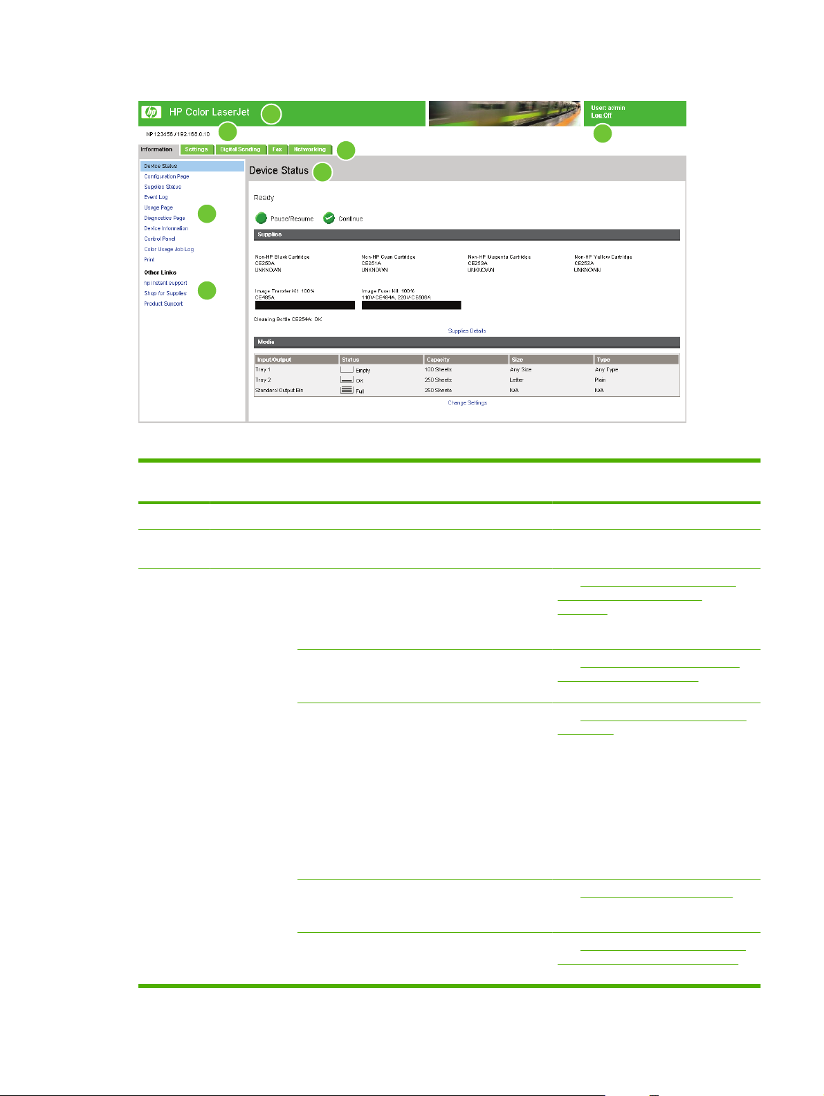
Figure 1-1 Sample HP EWS screen
1
2
3
7
4
5
Table 1-1 HP Embedded Web Server
6
Callout HP EWS
screen feature
1 Product name View the product name.
2 Product TCP/IP
address
3 Tabs Information tab View information about the
Description More information
View the Internet protocol (IP) address for the
product.
product. You cannot
configure the product
using the screens on this
tab.
Settings tab Use the features on this
tab to configure the
product.
Digital Sending tab Use the features on this
tab to configure the digital
sending capabilities.
NOTE: If the Digital
Sending Software
(HP DSS) has been
installed, the digital
sending options must be
configured by using the
HP MFP DSS
Configuration Utility.
See Viewing product status from the
HP EWS Information screens
on page 7.
See Configuring the product from the
Settings screens on page 25.
See Setting the digital sending options
on page 69.
Fax tab Configure fax settings and
manage the fax address
book.
Networking tab View network status and
configure the network
settings.
See Using fax functions on page 95.
See Managing network operation from
the Networking screens on page 105.
ENWW Navigating through the HP Embedded Web Server 5
Page 18

Table 1-1 HP Embedded Web Server (continued)
Callout HP EWS
screen feature
4 Menus Different on each tab Click a tab to display the
5 Other Links hp instant support Connect to a set of Web
6 Log In/Log Off Different for each
7 Screen Different for each
Description More information
menus.
resources that help solve
problems and describe the
additional services that
are available for your
HP product.
Shop for Supplies Use the Internet to order
genuine HP supplies for
your HP product.
Product Support Use product-specific help
from the HP Web site to
solve a problem.
Log in as an IT
type of user
menu item
administrator or service
provider.
Click a menu item to show
a screen.
Using the Other Links as a
See
●
resource on page 107.
See
●
●
●
See Login and logoff on page 4.
●
●
hp instant support
on page 107.
See
Product Support on page 109.
See
My Service Provider and My
Service Contract on page 109.
See Viewing product status from
the HP EWS Information screens
on page 7.
Configuring the product from
See
the Settings screens on page 25.
Managing network operation
See
●
from the Networking screens
on page 105.
6 Chapter 1 Overview ENWW
Page 19

2 Viewing product status from the
HP EWS Information screens
The screens available from the Information tab are for informational purposes only; you cannot
configure the product from these screens. To configure the product through the HP EWS, see
Configuring the product from the Settings screens on page 25.
NOTE: Some products do not support all screens.
ENWW 7
Page 20
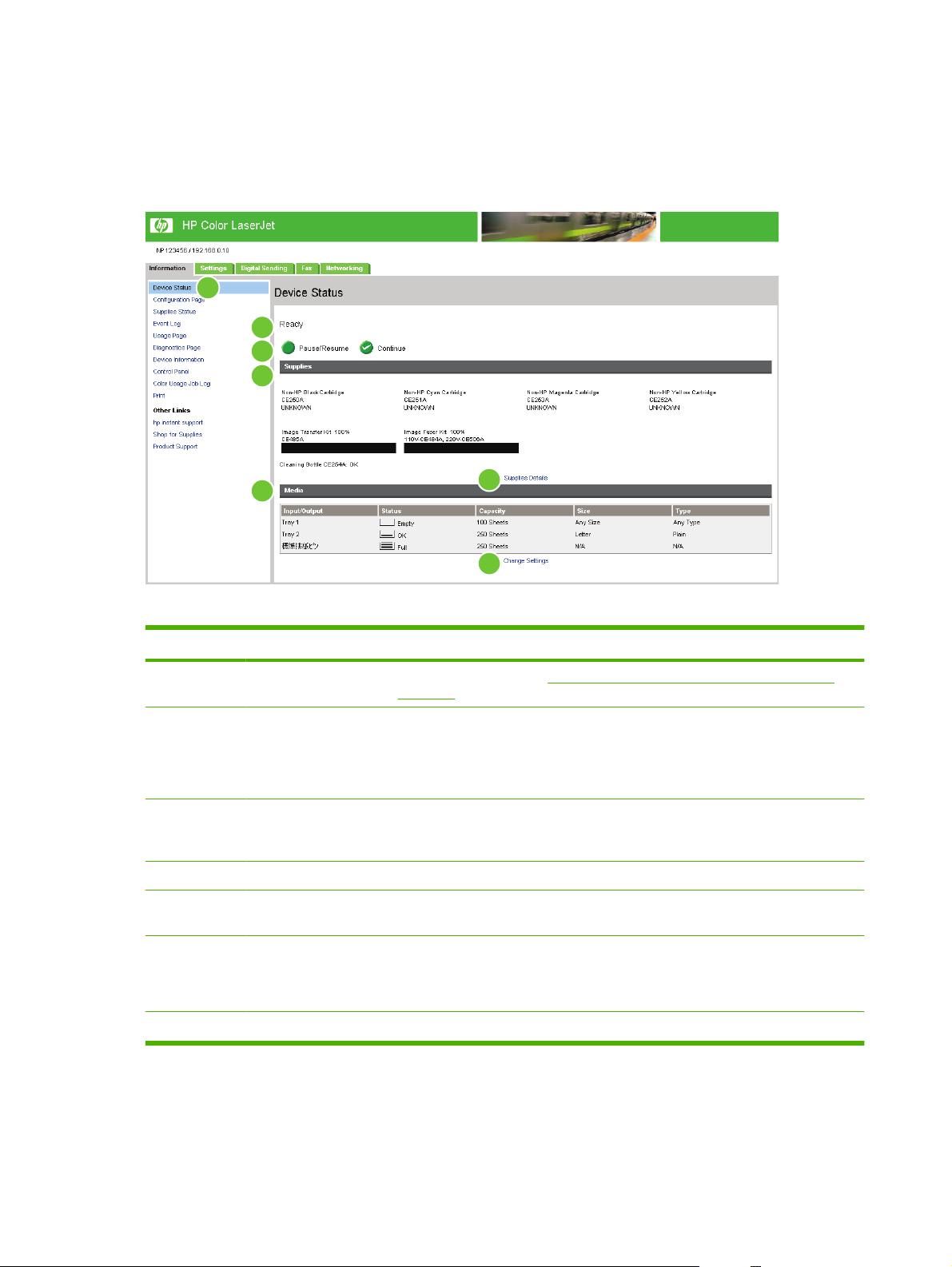
Device Status
Use the Device Status screen to view the current status of the product. The following illustration and
table describe how to use this screen.
Figure 2-1 Device Status screen
1
2
3
4
6
5
7
Table 2-1 Device Status
Callout Area on the screen Information or capability that the area provides
1 HP EWS tabs and
menus
2 Status Shows the device status (the same information that appears on the control-panel
3 Control-panel buttons Use these control-panel buttons just as you would at the product. To select which
4 Supplies Shows the percentage of life remaining for each supply.
5 Supplies Details Opens the Supplies Status screen, where you can view information about product
For more information, see Navigating through the HP Embedded Web Server
on page 4.
display).
If the device requires user intervention, a Help image appears in this area providing
instructions in a pop-up window.
control-panel buttons appear on this screen, go to the Security screen on the
Settings tab.
supplies.
6 Media Shows the status and configuration information for the input trays and output bins.
The media status is OK until the tray is completely empty. When the tray is empty,
the status is Out.
7 Change Settings Takes you to the Settings tab, where you can configure settings for the device.
8 Chapter 2 Viewing product status from the HP EWS Information screens ENWW
Page 21
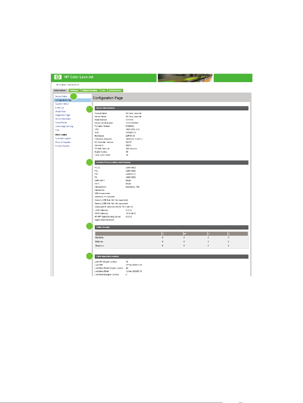
Configuration Page
Use the Configuration Page screen to view current product settings, help troubleshoot problems, and
verify the installation of optional accessories such as dual inline memory modules (DIMMs). The
following illustration and table describe how to use this screen.
Figure 2-2 Configuration Page screen – 1 of 2
1
2
3
4
5
ENWW Configuration Page 9
Page 22
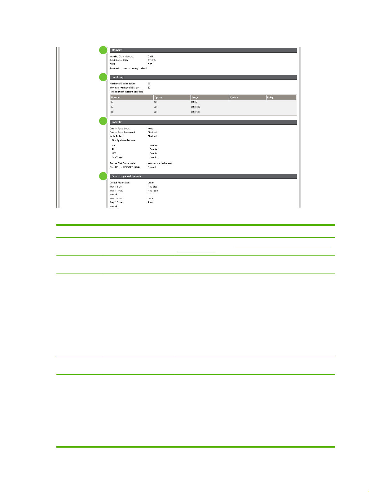
Figure 2-3 Configuration Page screen – 2 of 2
6
7
8
9
Table 2-2 Configuration Page
Callout Area on the screen Information or capability that the area provides
1 HP EWS tabs and menus For more information, see Navigating through the HP Embedded Web
Server on page 4.
2 Device Information Lists the serial number, version numbers, and other information for the
3 Installed Personalities and
Options
4 Color Density Lists the cyan, magenta, yellow, and black (CMYK) values for highlights,
5 Calibration Information Lists the last color-plane registration (CPR) page count, the last CPR
device.
Displays information about optional accessories and configurations. The
following information appears:
Version and TCP/IP address for all network devices connected to
●
the product (Jetdirect or internal Jetdirect)
All of the printer languages that are installed (such as printer
●
command language [PCL] and PostScript® [PS])
Options that are installed in each DIMM slot and EIO slot
●
USB devices that can be connected to a printer used as a host USB
●
controller, such as mass storage devices, card swipes, or keypads
midtones, and shadows.
page-count date, the last page count (in engine cycles) for DMAX/
DHALF, and the last DMAX/DHALF page-count date.
Color plane registration occurs when new print cartridges are installed
to compensate for any slight variations that might occur in cartridge
circumference.
DMAX is a density calibration of each print cartridge color at 100%
coverage; DHALF is also a density calibration of each print cartridge
color, but as a halftone instead of a full color. During halftone printing,
10 Chapter 2 Viewing product status from the HP EWS Information screens ENWW
Page 23

Table 2-2 Configuration Page (continued)
Callout Area on the screen Information or capability that the area provides
the dots of toner are spread out, and coverage of the toner is less than
100%.
6 Memory Lists the memory information, PCL Driver Work Space (DWS), and
7 Event Log Lists the number of active entries in the Event Log and the Event Log
8 Security Lists the status of the control-panel lock, disk write-protect options, and
9 Paper Trays and Options Lists the size and type of media that is specified for each of the trays in
resource saving information.
total capacity.
direct-connect (USB or parallel) ports.
You can change the status of the Direct Connect ports on the Security
screen under the Settings tab by selecting or clearing the Disable
Direct Ports check box.
the product. If a duplexing unit or any paper-handling accessories are
installed on the product, information about those devices is also listed
here.
ENWW Configuration Page 11
Page 24
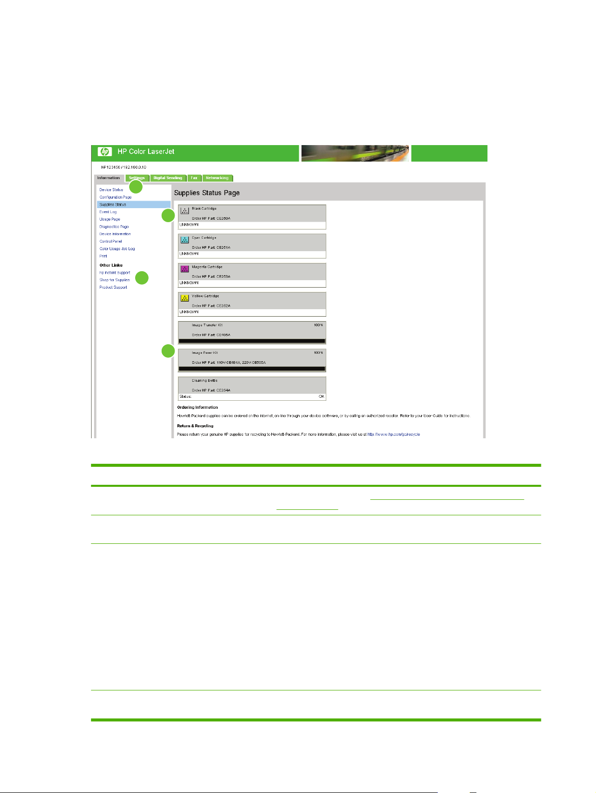
Supplies Status
The Supplies Status screen shows more detailed supplies information and provides part numbers for
genuine HP supplies. (It is helpful to have the part numbers available when ordering supplies.) The
following illustration and table describe how to use this screen.
Figure 2-4 Supplies Status screen
1
3
2
4
Table 2-3 Supplies Status
Callout Area on the screen Information or capability that the area provides
1 HP EWS tabs and menus For more information, see Navigating through the HP Embedded Web
2 Shop for Supplies link Use this feature to connect to a Web page that facilitates online ordering of
3 Print Cartridge Information If available, this lists the percent of life remaining and the estimated number
4 Long-Life Supplies
Information
Server on page 4.
supplies from a reseller of your choice.
of pages remaining before the supply is empty; the total number of pages
that have been processed with the supply; the supply serial number and
HP part number; and an indication of whether or not the supply has reached
the low status.
If the Override at Out option has been enabled at the product control panel,
a message appears, when the supply is exhausted, stating that the
cartridge was used with the override setting.
NOTE: If a non-HP supply is used, information about the device might not
be available. In addition, a warning message about the risks associated
with using non-HP supplies could appear on the screen. No further
information about the status of the supply will be available.
If available, this lists the percent of life remaining and the estimated number
of pages remaining with the supply.
12 Chapter 2 Viewing product status from the HP EWS Information screens ENWW
Page 25
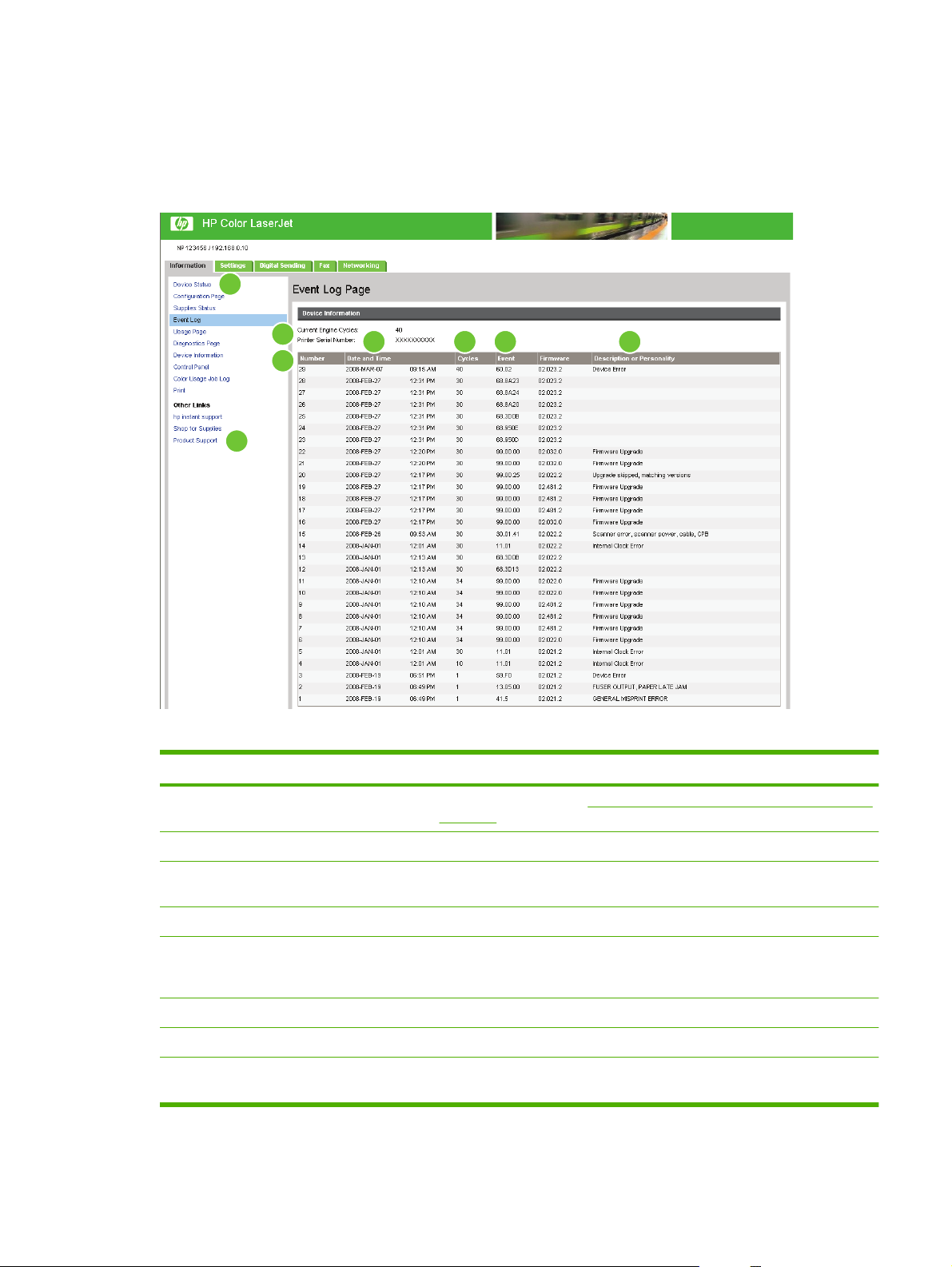
Event Log
The Event Log screen shows the most recent product events, including jams, service errors, and other
printer errors. The following illustration and table describe how to use this screen.
Figure 2-5 Event Log screen
1
4
526 7
3
8
Table 2-4 Event Log
Callout Area on the screen Information or capability that the area provides
1 HP EWS tabs and menus For more information, see Navigating through the HP Embedded Web Server
on page 4.
2 Current Engine Cycles Shows the number of engine cycles that the product has completed to date.
3 Number Lists the order in which the errors occurred. The last error to occur has the
highest number.
4 Date and Time Lists the date and time for each event logged.
5 Cycles Shows the number of engine cycles that the product had completed when the
error occurred. The product completes one engine cycle for every Letter/A4size page side that it prints or copies.
6 Event Shows the internal event code for each event.
7 Description or Personality Shows a brief description of some events.
8 Product Support link Provides access to the HP support Web site for product-specific
troubleshooting information.
ENWW Event Log 13
Page 26
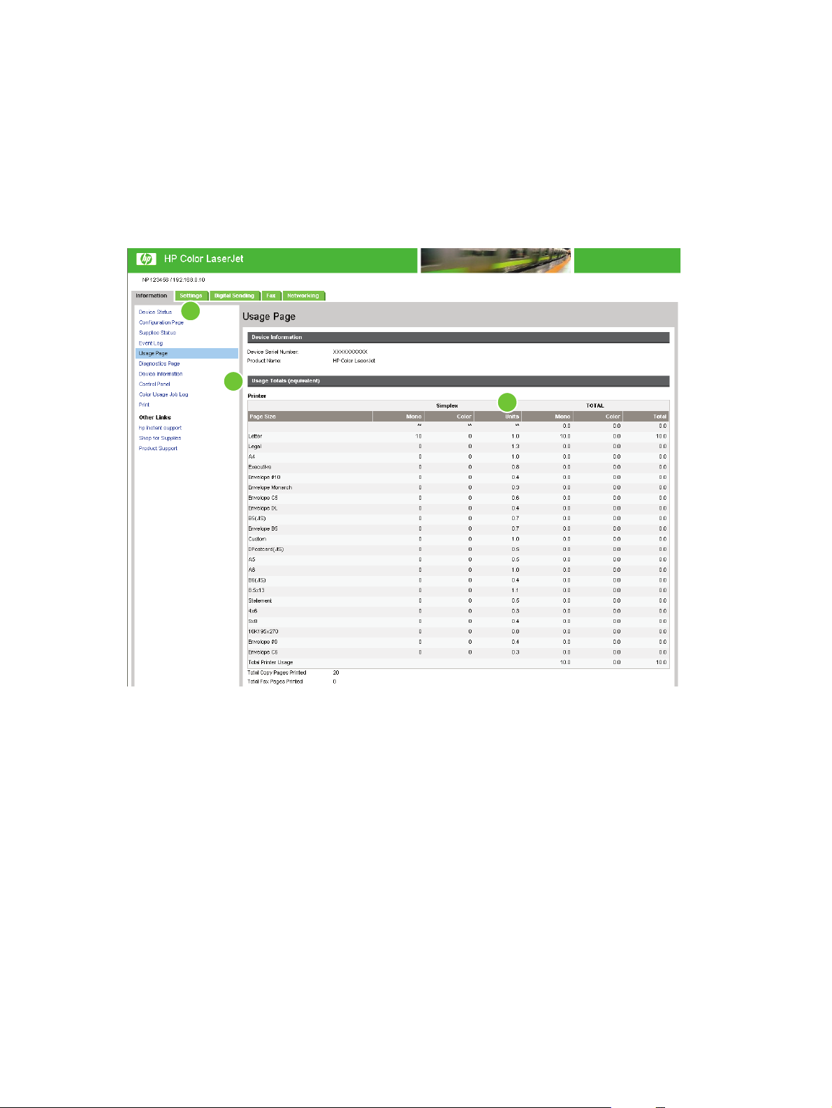
Usage Page
The Usage Page screen gives a page count for each media size of that has passed through the product,
as well as the number of duplexed pages. The total is calculated by multiplying the sum of the print count
values by the Units value.
The information on this screen can be used to determine how much toner or paper to keep on hand.
The following illustration and table describe how to use this screen.
Figure 2-6 Usage Page screen – 1 of 3
1
2
3
14 Chapter 2 Viewing product status from the HP EWS Information screens ENWW
Page 27
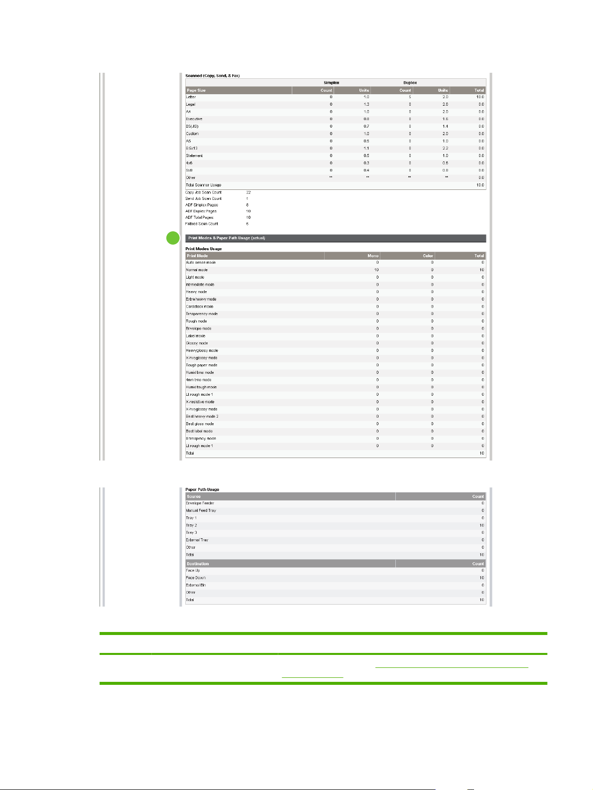
Figure 2-7 Usage Pagescreen – 2 of 3
4
Figure 2-8 Usage Pagescreen – 3 of 3
Table 2-5 Usage Page
Callout Area on the screen Information or capability that the area provides
1 HP EWS tabs and menus For more information, see Navigating through the HP Embedded Web
Server on page 4.
ENWW Usage Page 15
Page 28

Table 2-5 Usage Page (continued)
Callout Area on the screen Information or capability that the area provides
2 Usage Totals (equivalent) Indicates the types of pages that have been printed, the number of single-
sided pages that have been printed, the number of duplexed pages that
have been printed, and the total number of pages that have been printed.
3 Units A unit is equal to a standard A4-size (letter-size) page. All other page sizes
are referenced in relation to this standard size. An A4-size (letter-size) page
printed on both sides counts as 2 units.
4 Print Modes & Paper Path Usage
(actual)
Indicates the different print modes that have been used for color and
monochrome (black-and-white) print jobs.
16 Chapter 2 Viewing product status from the HP EWS Information screens ENWW
Page 29
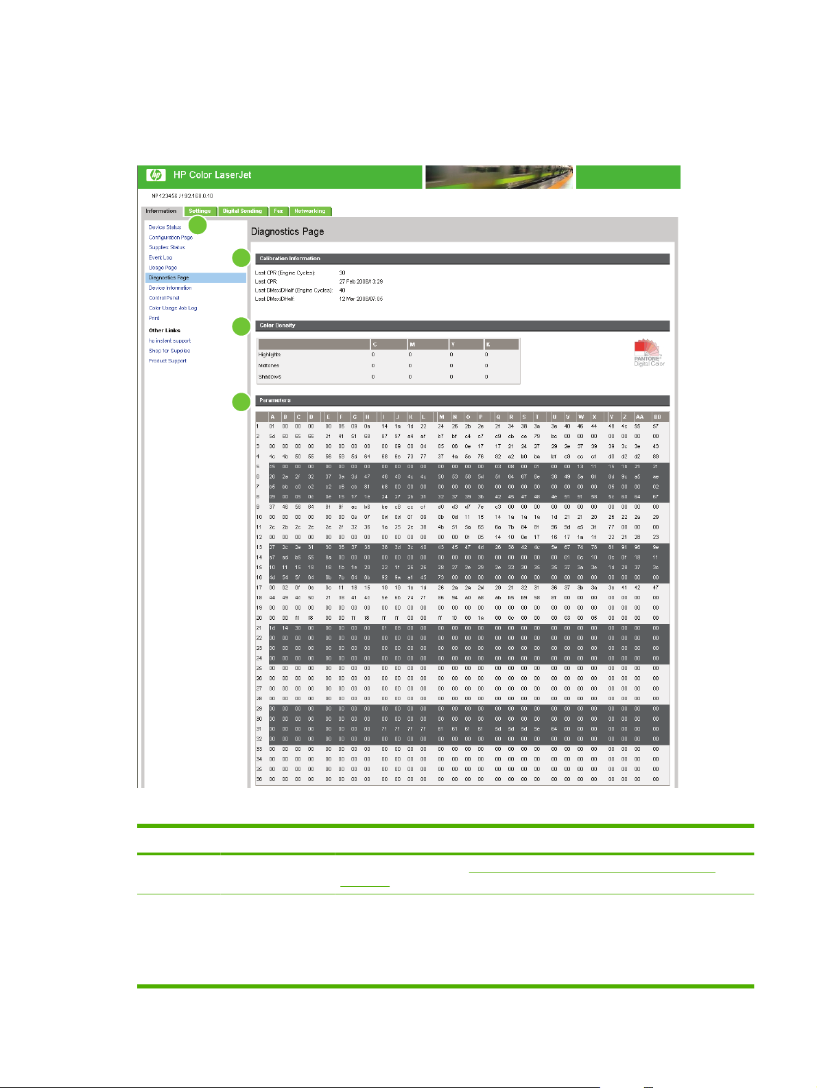
Diagnostics Page
The Diagnostics Page screen provides information about calibration, color density, and parameters.
Figure 2-9 Diagnostics Page screen
1
2
3
4
Table 2-6 Diagnostics Page
Callout Area on the screen Information or capability that the area provides
1 HP EWS tabs and
menus
2 Calibration
Information
For more information, see Navigating through the HP Embedded Web Server
on page 4.
Lists the last color-plane registration (CPR) page count, the last CPR page-count date,
the last page count (in engine cycles) for DMAX/DHALF, and the last DMAX/DHALF
page-count date.
Color plane registration occurs when new print cartridges are installed to compensate
for any slight variations that might occur in cartridge circumference.
ENWW Diagnostics Page 17
Page 30

Table 2-6 Diagnostics Page (continued)
Callout Area on the screen Information or capability that the area provides
DMAX is a density calibration of each print cartridge color at 100% coverage; DHALF
is also a density calibration of each print cartridge color, but as a halftone instead of
a full color. During halftone printing, the dots of toner are spread out, and coverage of
the toner is less than 100%.
3 Color Density Lists the cyan, magenta, yellow, and black (CMYK) values for highlights, midtones,
and shadows.
4 Parameters For color devices, specific engine settings related to the printing or
electrophotographic process are critical in identifying device status and function. The
electrophotographic parameters, which are used to detect, diagnose, and track printquality defects, appear in a 272-cell binary array that contains the settings registered
by the device engine. These registers also appear at the bottom of the Diagnostics
Page screen.
18 Chapter 2 Viewing product status from the HP EWS Information screens ENWW
Page 31

Device Information
The Device Information screen shows the following information:
Device name
●
Device location
●
Asset number
●
Company name
●
Contact person
●
Product name
●
Device model
●
Device serial number
●
The product name, device model, and device serial number are automatically generated. You can
configure the other information on this screen from the Device Information screen on the Settings tab.
Figure 2-10 Device Information screen
ENWW Device Information 19
Page 32

Control Panel Snapshot
The Control Panel Snapshot screen shows the product control-panel display as if you were standing
at the product. Because this view shows the product status, it can help you troubleshoot problems with
the product.
NOTE: The appearance of the screen might vary, depending on your product.
Figure 2-11 Control Panel Snapshot screen
20 Chapter 2 Viewing product status from the HP EWS Information screens ENWW
Page 33

Color Usage Job Log
Use the Color Usage Job Log to view usage details for the printer. The following illustration and table
describe how to use the Color Usage Job Log screen.
Figure 2-12 Color Usage Job Log screen
1
2
3
Table 2-7 Color Usage Job Log
Callout Area on the screen Information or capability that the area provides
1 Printer Information Lists the serial number and name of the printer.
2 Usage Totals Summarizes usage totals for all jobs, mono sides, color sides, and total sheets.
3 Job Log Displays usage data for the selected page in the log.
If a hard disk is installed on your product, the Job Log shows a maximum of 7,400
jobs. If a hard disk is not installed on your product, the Job Log shows a maximum
of 32 jobs.
Click Previous or Next to move through the log, or click the page number you wish
to see. The displayed data changes as you move through the log.
ENWW Color Usage Job Log 21
Page 34

NOTE: The Print screen (and the Print menu on the left) is available only if it has been configured to
appear on the Security screen under the Settings tab. Use the Security screen to disable the Print
screen if you do not want it to appear for security reasons. For more information, see
Security
on page 37.
Use the Print screen for print-ready files or to remotely update the product firmware.
Use the Print screen to print one file at a time from a product that supports the HP EWS. This feature
is especially useful for a mobile user, because you do not have to install the product's print driver to
print; you can print from anywhere at any time.
You can print all print-ready files, such as documents that have been generated by using a "print to file"
driver option. Print-ready files commonly have file name extensions such as .PS (postscript), .PDF
(Adobe Portable Document Format), and .PRN (Windows print-ready File).
This feature is especially useful because you do not have to install additional software to update the
product firmware. When updated firmware files are available for your product, simply download them
from your product support Web site:
http://www.hp.com/support/CM3530mfp
The following illustration and table describe how to use this screen.
Figure 2-13 Print screen
1
2
3
Table 2-8 Print page
Callout Area on screen Information or capability that the area provides
1 HP EWS tabs and
menus
2 Device Status Shows the device status (the same information that appears on the Device Status
3 Choose File Prints a print-ready file, such as a .pdf or .txt file, that is located on your laptop,
For more information, see Navigating through the HP Embedded Web Server
on page 4.
screen and the control-panel display).
computer, or a network file server.
22 Chapter 2 Viewing product status from the HP EWS Information screens ENWW
Page 35

Printing a file or updating firmware from the Print screen
Use the following procedure to print a file or update product firmware from the Print screen.
1. Click Browse to locate a file on your machine or network to print.
2. Click Apply.
ENWW Print 23
Page 36

24 Chapter 2 Viewing product status from the HP EWS Information screens ENWW
Page 37

3 Configuring the product from the
Settings screens
Use the screens on the Settings tab to configure the product from your computer.
Configure Device
Use the Configure Device screen to print device information pages and remotely configure the device.
The menus on this screen are similar to the menus available at your device control panel. Some of the
device control-panel menus are not available from the HP EWS. See the documentation that came with
your device for more information about menus supported by your device.
The following illustration, table, and example procedure describe how to use this screen.
Figure 3-1 Configure Device screen
1
2
3
Table 3-1 Configure Device
Callout Area on the screen Information or capability that the area provides
1 HP EWS tabs and
menus
For more information, see Navigating through the HP Embedded Web Server
on page 4.
ENWW Configure Device 25
Page 38

Table 3-1 Configure Device (continued)
Callout Area on the screen Information or capability that the area provides
2 Select A Menu Information menu Print device information pages, which provide details
about the device and its configuration.
Default Job Options menu Use this menu to define the default job options for
each function.
Time/Scheduling menu Use this menu to set options for setting the time and
for setting the device to enter and exit sleep mode.
Management menu Use this menu to set up global device-management
options.
Initial Setup menu The Initial Setup menu allows access to setup
screens for Network and I/O, Fax, and E-mail.
Device Behavior menu Use this menu to determine the language, sounds,
timeout, and error behavior for the device.
Print Quality menu Use this menu to control the Print Quality settings for
the device.
Troubleshooting menu Get information about the device that you can use to
troubleshoot problems.
Resets menu Use this menu to restore settings to the initial setup
values.
3
Plus sign (
)
Click the plus sign next to a menu, or click the menu, to see the submenus or
subentries.
Using the menus on the Configure Device screen
The following procedure is provided only as an example. Similar procedures can be used to set other
menu items.
Follow these steps to print a Demonstration Page (example procedure).
1. Click INFORMATION.
2. Click Sample Pages/Fonts.
3. Select the check box for the Demonstration Page, and then click Apply. The device prints the
page.
NOTE: Print drivers and software programs frequently override selections that are made on the
Printing menu and the Paper Handling menu. For more information, see the user guide that came with
your product. Any changes are reflected on the Device Status screen, the Configuration Page screen,
and the Paper Handling menu.
26 Chapter 3 Configuring the product from the Settings screens ENWW
Page 39

Tray Sizes/Types
Use the Tray Sizes/Types screen to assign paper sizes and paper types for each tray on the product.
The following illustration and table describe how to use this screen.
Figure 3-2 Tray Sizes/Types screen
1
2
Table 3-2 Tray Sizes/Types
Callout Area on the screen Information or capability that the area provides
1 HP EWS tabs and menus For more information, see Navigating through the HP Embedded Web Server
on page 4.
2 Tray Sizes and Tray
Types
Use these menus to select the default paper sizes and types for each tray on the
product.
ENWW Tray Sizes/Types 27
Page 40

E-mail Server
Use the E-mail Server screen to configure e-mail settings for outgoing e-mail. Use the settings on this
screen to send and receive e-mail messages, including product alerts. The following illustration, table,
and procedures describe how to use this screen.
Figure 3-3 E-mail Server screen
1
2
3
4
Table 3-3 E-mail Server
Callout Area on the screen Information or capability that the area provides
1 HP EWS tabs and menus For more information, see Navigating through the HP Embedded
Web Server on page 4.
2 Outgoing e-mail Configure outgoing e-mail if you intend to use the Alerts or
AutoSend features. For more information, see
screen with a product on page 32.
3 Return E-mail Address This is the device's e-mail address that appears in device alerts.
For more information, see
on page 29
4 Enable SMTP Authentication If your SMTP server requires authentication, type the credentials
here.
Configuring the return e-mail address
Using the Alerts
28 Chapter 3 Configuring the product from the Settings screens ENWW
Page 41

Configuring outgoing e-mail
You must configure outgoing e-mail if you intend to use the Alerts or AutoSend features.
1. Gather the following information. (Your organization's network or e-mail administrator typically
provides the information that is required to configure outgoing mail.)
The TCP/IP address of the simple mail transfer protocol (SMTP) mail server on your network.
●
The EWS uses the SMTP server TCP/IP address to relay e-mail messages to other
computers.
The e-mail domain name suffix that is used to address e-mail messages within your
●
organization.
2. Select the Enable Outgoing E-mail check box.
3. Type the SMTP server TCP/IP address in the SMTP Server text box.
4. Type the domain name in the Domain Name text box.
5. Click Apply to save the changes.
Configuring the return e-mail address
When you configure the return e-mail address on the E-mail Server page, you are configuring the
identity of the product. For example, if you type anyone in the Username field and
yourcompany.com in the Domain Name field, all e-mails sent out by the product will come from
anyone@yourcompany.com
In this example, the identity of the product is:
anyone@yourcompany.com
ENWW E-mail Server 29
Page 42

Alerts
From the Alerts screen, IT administrators can set up the product to send problem and status alerts to
anyone through e-mail messages. When this function is configured, alerts are automatically triggered
about supplies, paper-path status, and other service and advisory information. More than one individual
can receive alerts, with each person receiving only specific alerts. For example, an administrative
assistant might be responsible for ordering print cartridges or fixing jams, and could receive advanced
warning when toner is low or a jam occurs. Similarly, the long-life supplies might be handled by an
external service provider, who could receive alerts about performing product maintenance, loading the
front or rear stapler, and similar needs.
NOTE: A user can create up to four different destination lists, with up to 20 recipients on each list.
By selecting the Remove Control Panel Supplies Status Messages option (available on the Alerts setup screen that appears when you press the New Destination List button), you can suppress the
Cartridge low or Cartridge out supplies status messages on the control panel. The control panel
message is suppressed only when you select one or both of these alerts.
The following illustration, table, and procedures describe how to use this screen to edit, test, and delete
destinations and destination lists.
NOTE: In order for alerts to function, outgoing e-mail must be enabled. To enable outgoing e-mail,
Configuring outgoing e-mail on page 29.
see
Figure 3-4 Alerts screen
1
2
5
4
3
6
Table 3-4 Alerts
Callout Area on the screen Information or capability that the area provides
1 HP EWS tabs and menus For more information, see Navigating through the HP Embedded Web Server
on page 4.
2 Destination list summary Lists the current selections for each destination.
3 Edit Click this button to make changes to the destination or destination list.
4 Test Click this button to send a test alert to the destination or destination list.
30 Chapter 3 Configuring the product from the Settings screens ENWW
Page 43

Table 3-4 Alerts (continued)
Callout Area on the screen Information or capability that the area provides
5 Delete Click this button to delete the destination or destination list.
6 New Destination List Click this button to define the settings for a new destination list for alerts.
ENWW Alerts 31
Page 44

Using the Alerts screen with a product
You can set up four different lists, with up to 20 recipients on each list.
The Alerts - setup screen that appears when you click either Edit or New Destination List looks similar
to the following illustration.
Figure 3-5 Alerts - setup screen – 1 of 2
Figure 3-6 Alerts - setup screen – 2 of 2
32 Chapter 3 Configuring the product from the Settings screens ENWW
Page 45

To configure alerts
1. Do one of the following:
●
●
The Alerts - setup screen appears.
2. Type a name in the List Name field, such as Service or Supplies.
3. Type the e-mail addresses to designate the people who will receive alerts. In large environments,
system administrators can route e-mail addresses to list servers, URLs, and mobile devices for
expanded alerts. Add multiple destinations by separating each destination with a comma or
semicolon.
4. Select the check box for the alerts that you want sent with this destination list. (To see all of the
alerts that are available for the product, click Show All Alerts.)
5. Where applicable, set the threshold value for the individual alerts.
The threshold value for service alerts and for the paper-path alerts is a user-specified number of
minutes. This is the amount of time that an event will be ignored before an e-mail alert message
is sent. For example, you might want to set the threshold value for the "Tray Open" alert to 10
minutes to allow someone to close the tray after loading the tray or clearing a jam.
To create a new destination list, click New Destination List.
-Or-
To modify an existing destination list, click Edit next to the list that you want to modify.
6. Under Select Control Panel Messages to Suppress, select messages that you do not want to
appear on the product control panel. This step applies only to messages that were selected to be
received as alerts.
NOTE: If the browser does not accept JavaScript, the check box for message suppression is
always enabled. The check-box selection is validated when pressing the Apply button to submit
the page. If the corresponding suppression alerts have not been selected, the Alerts - setup screen
is reloaded with a warning message. The message warns that you must first select the
corresponding alerts to suppress their appearance on the control panel.
7. Select the attachments to include with your e-mail alert messages. These attachments may include
the following pages. (Go to the Information tab to see examples of these pages.)
Supplies Status Page
●
Usage Page
●
Configuration Page
●
Event Log Page
●
XML Data
●
Select the XML Data option if one of the destinations you have chosen to receive alerts is an
automated computer system. Each item that you select will be attached to the e-mail. For example,
if you select Usage Page and Event Log Page, you will receive one e-mail message with two
attachments, one for each selection. If you also select the XML Data option, you will receive one
e-mail message with three attachments: one attachment for the Usage Page in HTML, one for the
Event Log in HTML, and a third consisting of instant support information in a text file attachment
that has an .XML extension.
ENWW Alerts 33
Page 46

8. Click Apply to save the information.
9. Repeat steps 1 through 8 for each additional list or destination.
Use the following procedure to test the destination list configuration.
To test the configuration of a destination list
1. Click the Test button (see
want to test.
The following window appears.
Figure 3-7 Alerts - test screen
Figure 3-4 Alerts screen on page 30) next to the destination list that you
2. Select the destinations that you want to test.
3. The return address is the product's e-mail address. Type your e-mail address in the Return
Address box if you would like to receive messages about any errors that are generated from the
test alert (for example, to be notified of an incorrect destination address).
4. If applicable, type additional information that you would like to appear at the beginning of the e-
mail alert message in the Your Notes (optional) text field.
5. Click OK.
34 Chapter 3 Configuring the product from the Settings screens ENWW
Page 47

To delete destinations and destination lists
1. If you have multiple destinations configured, you can delete a destination or destination list by
clicking the Delete button next to the destination or destination list that you want to delete.
2. Click OK to confirm the deletion.
AutoSend
Use the AutoSend screen to send product-configuration and supplies-usage information periodically to
e-mail destinations of your choice, such as service providers. This feature establishes a relationship
with Hewlett-Packard Company or another service provider to provide you with services that include,
but are not limited to, print-cartridge replacement, pay-per-page contracts, support agreements, and
usage tracking. A user can add up to twenty AutoSend destinations. The following illustration, table, and
procedure describe how to use this screen.
Figure 3-8 AutoSend screen
1
2
3
4
6
5
Table 3-5 AutoSend
Callout Area on the screen Information or capability that the area provides
1 HP EWS tabs and menus For more information, see Navigating through the HP Embedded Web Server
on page 4.
2 Enable AutoSend Select this check box to turn on the AutoSend feature.
3 Send every [interval] Select the interval at which you want the product to send the product configuration
4 E-Mail destinations Save a list of up to 20 e-mail addresses to receive the product-configuration
and supplies usage information to the destinations that are configured in the
E-Mail destinations field.
information. The first e-mail address can be no more than 50 characters long.
5 Send to HP Select this check box to send device configuration and supplies status information
to HP on a regular basis. The information will be sent to an HP e-mail address
ENWW AutoSend 35
Page 48

Table 3-5 AutoSend (continued)
Callout Area on the screen Information or capability that the area provides
6 Test Click this button to save your settings and to send the information immediately,
To turn on the AutoSend feature
Use the following procedure to make the AutoSend feature available.
1. Make outgoing e-mail functions available by following the instructions that are listed in this chapter.
(For more information, see
2. Select the Enable AutoSend check box.
3. Click an option to specify the interval at which you want the product to send the product-
configuration and supplies-usage information to the e-mail recipients (determined in the next step),
and then type the number of days, weeks, months, or pages printed.
4. Configure up to 20 destinations using the form that appears on the screen.
E-mail Server on page 28.)
(for example, myproduct@hp.com) in a text-based file with an .XML file extension.
This file will be created in English.
To view more information about how HP treats the information that is sent by
AutoSend, click Hewlett-Packard Online Privacy Statement.
so that you can make sure that the recipient receives the messages.
5. To send device configuration and supplies status information to HP, select the Send to HP check
box.
6. Click Apply.
36 Chapter 3 Configuring the product from the Settings screens ENWW
Page 49

Security
The following illustration and table describe how to use the Security screen.
Figure 3-9 Security screen
1
2
3
4
5
Table 3-6 Security
Callout Area on the screen Information or capability that the area provides
1 HP EWS tabs and menus For more information, see Navigating through the HP Embedded Web Server
2 HP Jetdirect Security
Configuration Wizard button
3 Configure Security Settings
button
4 Perform Secure Storage Erase
button
on page 4.
The HP Jetdirect Security Configuration Wizard button allows you to
configure security settings for the device's HP Jetdirect print server.
The Configure Security Settings button allows you to configure security
settings for the device's management and printing systems.
The Perform Secure Storage Erase button allows you to perform disk wipes
that will remove all data that has been stored on any mass storage unit
attached to the device.
NOTE: The settings for the type of Secure Storage Erase to be performed
can be configured in the File Erase Mode section of the device's security
settings page.
ENWW Security 37
Page 50

Table 3-6 Security (continued)
Callout Area on the screen Information or capability that the area provides
5 Status of Security Settings This section presents a summary of the current security settings on the
Configure Security Settings
Use the Configure Security Settings screen to set the desired levels of security. The following
illustration and table describe how to use this screen.
Figure 3-10 Configure Security Settings screen – 1 of 2
NOTE: The device's file system password must be set before a Secure
Storage Erase operation can be performed. The file system password can
be set in the File System Password section of the device's security settings
page. See
NOTE: This button does not appear if the device does not have a mass
storage device installed.
device. These settings can be modified by clicking on the Configure
Security Settings button.
Configure Security Settings on page 38.
1
2
3
4
38 Chapter 3 Configuring the product from the Settings screens ENWW
Page 51

Figure 3-11 Configure Security Settings screen – 2 of 2
5
6
7
8
9
Table 3-7 Configure Security Settings
Callout Area on the screen Information or capability that the area provides
1 Device Password Use this feature to set your password using a maximum of 16 characters.
The device password allows you to control who can access and change
device settings.
To assign or change the device password:
1. If the device currently has a password assigned, type the current device
password in the Old Password text box.
2. Type the new device password you want to use in the New
Password text box.
3. Type the same device password in the Verify Password text box.
4. Click Apply at the bottom of the page.
5. An authorization dialog box appears. Use the new password to re-
authenticate to the device.
ENWW Security 39
Page 52

Table 3-7 Configure Security Settings (continued)
To disable the device password:
1. Type the current device password in the Old Password text box.
2. Leave the New Password and Verify Password text boxes blank.
3. Click Apply at the bottom of the page.
4. An authorization dialog box appears. Use the new password to re-
authenticate to the device.
2 PJL Password PJL (Printer Job Language) is a command language that enables some
features of the printer such as banner pages. Setting the PJL password locks
access to these PJL features.
Set the PJL password so that only authorized users can access PJL enabled
features. The PJL password can be any number between 1 and 2147483647.
3 File System Password Use this feature to prevent unauthorized users from changing any file system
configuration options and from performing a secure storage erase operation.
The file system password must be set to perform a secure storage erase
operation and to configure the secure file erase modes and the file system
external access. The File System Password can be up to 8 characters long.
4 File System Access Settings Use this feature to select which subsystems or embedded printer languages
have access to the device file systems.
NOTE: The File System Password must be configured before these
settings can be modified.
5 File Erase Mode Determines the behavior of a secure storage erase operation and the erase
operation that the printer automatically performs to make space available on
a hard disk drive for incoming print jobs.
The erase operations are designed to add available space to the printer's
hard disk drive, and to prevent unauthorized users from accessing
confidential information from the printer's hard disk drive or other erasable
storage device.
NOTE: The File System Password must be configured before these
settings can be modified.
The following erase modes are available. See row four in
on page 37 for more information.
Non-Secure Fast Erase. When a Secure Storage Erase is performed,
●
files on the mass storage device are not actually deleted. Rather, the
reference to the files in the file system tables is removed.
Secure Fast Erase. When a Secure Storage Erase is performed, file
●
information is overwritten with a random character pattern when it is
deleted.
Secure Sanitize Erase. When a Secure Storage Erase is performed,
●
a secure, repetitive algorithm is used to overwrite all file information and
remove any residual data persistence. A random character is written to
all bytes of deleted sectors. Then the complement of that character is
written, and finally, another random character is written. The device
might restart a number of times during this process.
Table 3-6 Security
6 Control Panel Access Lock Use this feature to lock the device control panel, preventing unauthorized
users from accessing it and changing the device settings. Users can still read
the settings on the printer’s control panel.
40 Chapter 3 Configuring the product from the Settings screens ENWW
Page 53

Table 3-7 Configure Security Settings (continued)
The following options are available.
Unlock menu. Allows full control panel access.
●
Minimum Menu Lock. Locks out the RESETS MENU,
●
CONFIGURATION MENU, and the I/O MENU.
Moderate Menu Lock. Locks out the menus locked by the Minimum
●
Menu Lock, plus the PRINT QUALITY MENU and the PAPER
HANDLING MENU.
Intermediate Menu Lock. All items in the following menus are locked
●
out:
◦
◦
◦
◦
NOTE: Intermediate Menu Lock is a stand-alone menu. It does not
build on other menus.
Maximum Menu Lock. Locks out the menus locked by Minimum Menu
●
Lock and Moderate Menu Lock, plus the PRINTING MENU,
INFORMATION MENU, and the Job Cancel key.
PAPER HANDLING MENU
CONFIGURE DEVICE MENU
DIAGNOSTICS MENU
SERVICE MENU
NOTE: If the menu item is locked, any attempt by the user to change a
variable from the front panel will generate a warning on the control panel
display indicating that the control panel menus are locked.
7 Embedded Web Server
Options
8 Options for Services Use this feature to enable services for the printer:
9 Direct Ports (USB/IEEE 1284) Use this feature to force users to communicate with the device over a
Use this feature to display or hide Embedded Web Server pages as well as
to enable or disable some capabilities of the device.
Remote Firmware Upgrade. Allows you to enable or disable upgrades
●
to the device firmware.
Service Loading. Allows you to enable or disable the ability for third-
●
party applications to load custom services on the device.
Job Retention. Allows you to enable or disable Job Retention
●
capabilities (Job Hold, Proof, Store, and PIN Printing).
network. Setting this option allows more control of device usage by enforcing
network defined permissions.
When this setting is applied, the device turns off and then back on to disable
the direct port.
HP Jetdirect Security Configuration Wizard
Use the HP Jetdirect Security Configuration Wizard to configure security settings for HP Jetdirect
print server management.
HP Web Jetadmin is a powerful web-based software utility for installing, configuring, and managing
network-connected devices. Since it can install and configure devices, it must be able to secure itself
ENWW Security 41
Page 54

against unwanted access. Not only can it secure itself against unwanted users, it can also secure the
devices it manages against unwanted access. Securing devices is important for the following reasons:
Reduce printer down time
●
Reduce help desk calls
●
Minimize troubleshooting visits
●
Minimize consumable usage
●
NOTE: If you use HP Web Jetadmin to configure your printer, HP recommends that you configure HP
Jetdirect security settings with HP Web Jetadmin.
As HP Jetdirect firmware is enhanced or revised, performance and security issues are addressed.
Always keep the firmware on the printer at the latest revision level to ensure maximum security. HP Web
Jetadmin provides the ability to upgrade HP Jetdirect firmware either individually or in batches.
The following illustration describes how to use this screen.
Figure 3-12 HP Jetdirect Security Configuration Wizard
42 Chapter 3 Configuring the product from the Settings screens ENWW
Page 55

Authentication Manager
Use the Authentication Manager screen to set the Device Functions that require users to successfully
log in before use. The following illustration and table describe how to use this screen.
Figure 3-13 Authentication Manager screen
1
2
3
4
Table 3-8 Authentication Manager
Callout Area on the screen Information or capability that the area provides
1 HP EWS tabs and
menus
2 Home Screen Access Specify a log-in method for users gaining access to the Home screen.
3 Device Functions Specify a log-in method for users gaining access to the following functions:
4 Future Installations Specify a log-in method for users gaining access to any new features to be installed
For more information, see Navigating through the HP Embedded Web Server
on page 4.
Copy
●
Color Copy
●
Send to E-mail
●
Send Fax
●
Send to Folder
●
Job Storage
●
Create Stored Job
●
Digital Sending Service (DSS) Secondary E-mail
●
Digital Sending Service (DSS) Workflow
●
in the future.
ENWW Authentication Manager 43
Page 56

LDAP Authentication
Use the LDAP Authentication page to configure a Lightweight Directory Access Protocol (LDAP) server
to authenticate device users. When LDAP authentication is selected as the Log In Method for one or
more Device Functions on the Authentication Manager page, the user at the device must enter valid
credentials (username and password) to gain access to those functions.
Authentication consists of two interdependent parts. First, the device verifies the user's credentials with
the LDAP server. After the device user has supplied valid credentials and has been authenticated, the
device searches for the user's e-mail address and name. If either step fails, the user is denied access
to the functions that have been configured to require LDAP authentication.
Use the LDAP Authentication page to set up the parameters that are used to access the LDAP server
and searches for the user's information. Note that this page only applies when LDAP is selected as a
Log In Method on the Authentication Manager page. The following illustration and table describe how
to use this screen.
Figure 3-14 LDAP Authentication screen
1
2
3
4
5
6
7
8
9
11
Table 3-9 LDAP Authentication
Callout Area on the screen Information or capability that the area provides
1 HP EWS tabs and
menus
2 LDAP Server Bind
Method
10
For more information, see Navigating through the HP Embedded Web Server
on page 4.
The LDAP Server Bind Method setting determines how the device will access the
LDAP server. Contact your LDAP server administrator to determine which method
will work best for you.
Simple - The selected LDAP server does not support encryption. Note that the
●
password, if any, will be sent unencrypted across the network.
Simple over SSL - The selected LDAP server supports encryption using the
●
Secure Sockets Layer (SSL) protocol. All data, including the username and
password, will be encrypted. The LDAP server must be set up to support SSL,
including configuring a certificate that establishes its identity.
44 Chapter 3 Configuring the product from the Settings screens ENWW
Page 57

Table 3-9 LDAP Authentication (continued)
Callout Area on the screen Information or capability that the area provides
Also, the device network interface must be configured with a Certificate Authority
(CA) certificate to validate the LDAP server. The CA certificate is configured on
the Networking tab of the Web interface. In some LDAP server configurations,
a client certificate is also required and is configured on the same Networking
tab.
3 LDAP Server The LDAP Server setting is the host name or IP address of the LDAP server to be
used to authenticate device users. When using SSL, the name or address typed here
must match the name in the certificate that the server sends.
Multiple servers can be included in this field by separating their addresses with a
vertical bar ('|', ASCII 0x7c) character. This feature can be used, for example, to
specify primary and backup servers. The network interface only supports a single
Certificate Authority (CA) certificate, so all the LDAP servers in the list must use the
same CA.
4 Port The Port setting refers to the TCP/IP port number on which the server is processing
5 Use Device User's
Credentials
6 Use LDAP
Administrator's
Credentials
7 Bind and Search Root When the Use Device User’s Credentials method is selected, the Bind and Search
LDAP requests. Typically, this is port 389 for Simple binds or 636 for Simple over SSL
binds.
The Use Device User's Credentials method uses the Bind Prefix, the string that the
user enters at the control panel, and the Bind and Search Root to construct the User
DN. The constructed User DN is used to authenticate the user.
The Bind Prefix setting is the LDAP attribute used to construct the user's
Distinguished Name (DN) for authentication. This prefix is combined with the
username typed at the control panel to form the Relative Distinguished Name (RDN).
Commonly used prefixes are "CN" (for common name) or "UID" (for user identity).
Use Administrator’s Credentials attempts to search for the user’s DN instead of trying
to construct it.
The Administrator DN is the DN (Distinguished Name) of a user who has read access
to the LDAP directory. The account entered here does not have to have administrative
access to the directory. Read access is sufficient.
The Administrator Password is the password of the user whose user DN was entered
in the Administrator DN field.
Root value is used during both phases of authentication. During the credential
verification phase, this value is combined with the RDN to construct the full
Distinguished Name (DN) of the user. During the user information searching phase,
this value is the DN of the LDAP entry where the search begins.
When the Use LDAP Administrator's Credentials method is selected, the Bind and
Search Root is only used as a search root. The Search Root of the base of the LDAP
directory can be specified, and the device will search the entire LDAP tree for the user
object corresponding to the username entered at the device.
8 Match the name entered
with the LDAP attribute
of
9 Retrieve the device
user's e-mail address
using attribute of
10 and name using the
attribute of
11 Test Use the Test feature to test the validity of your settings before applying them. When
When searching for the device user's information in the LDAP database, the contents
of the attribute specified in this field are compared to the username that was typed
during authentication. This attribute is usually the same as the Bind Prefix.
After the device user has been located in the LDAP database, the user's e-mail
address is retrieved from the database by using the LDAP attribute specified in the
e-mail address using attribute of field.
The user's display name is obtained from the LDAP attribute that is specified in the
name using attribute of field.
you click this button, you are asked to provide user credentials as if you were logging
in at the device control panel. If the credentials that you provide are authenticated
ENWW LDAP Authentication 45
Page 58

Table 3-9 LDAP Authentication (continued)
Callout Area on the screen Information or capability that the area provides
and the user information is found in the LDAP database, a success message appears.
Otherwise, an error message appears indicating why authentication failed.
46 Chapter 3 Configuring the product from the Settings screens ENWW
Page 59

Kerberos Authentication
Use the Kerberos Authentication page to configure the device (multi-function peripheral or digital sender)
to authenticate users to a Kerberos Realm. When Kerberos authentication is selected as the Log In
Method for one or more Device Functions on the Authentication Manager page, the user at the device
must enter valid credentials (username, password, and realm) to gain access to those functions.
Authentication consists of two interdependent parts. First, the device verifies the user's credentials with
the KDC. Second, the device searches for the user's e-mail address and name. If either step fails, the
user is denied access to the functions that have been configured to require Kerberos authentication.
Use the Kerberos Authentication page to set up the parameters that are used to access the LDAP server
and to search for the user's information. Note that this page only applies when Kerberos Version 5 is
selected as a Log In Method on the Authentication Manager page.
The following illustration, table, and procedures describe how to use this screen.
Figure 3-15 Kerberos Authentication screen
1
2
5
3
4
6
7
8
9
10
11
12
13
14
Table 3-10 Kerberos Authentication
Callout Area on the screen Information or capability that the area provides
1 HP EWS tabs and menus For more information, see Navigating through the
2 Kerberos Default Realm The Kerberos Default Realm is the fully qualified domain
3 Kerberos Server Hostname The Kerberos Server Hostname can be the same as the
ENWW Kerberos Authentication 47
HP Embedded Web Server on page 4.
name of the Kerberos realm (domain).
Kerberos Default Realm if a DNS service is available
Page 60

Table 3-10 Kerberos Authentication (continued)
Callout Area on the screen Information or capability that the area provides
(Domain Name Service) and correctly configured. The
device will use DNS to look up the first available KDC
(Kerberos Domain Controller) on the network. If DNS is
not available, the IP address of the Kerberos Server may
be used.
4 Kerberos Server Port The Kerberos Server Port is the default IP port used by
the Kerberos authentication method. Note that the default
is port 88, but this can be different in different network
environments. Please contact your IT administrator to
determine the appropriate port if the default port does not
work.
5 Advanced button Use the Advanced button to the right of the Kerberos
Default Realm field to access the Alternate Domain
configuration. Alternate domains are mapped to the
default realm.
6 LDAP Server Bind Method The LDAP Server Bind Method determines how the
device will access the LDAP server.
7 Credentials The Credentials configuration section is used to
8 Bind Prefix The Bind Prefix setting is the LDAP attribute used to
determine which credentials will be used to bind
(authenticate) to the LDAP server.
When Use Device User Credentials is selected, the
●
device users credentials (entered at the control
panel of the device) will be used to access the LDAP
server. This method has the advantage of not having
to store a username and password, which may
expire, in the device.
When Use Public Credentials is selected and user
●
credentials are not available, the Username and
Password entered will be used to access the LDAP
server. This method should be used if for some
reason device users do not have read access to the
LDAP data.
construct the user's Distinguished Name (DN) for
authentication. This prefix is combined with the username
typed at the control panel to form the Relative
Distinguished Name (RDN). Commonly used prefixes are
"CN" (for common name) or "UID" (for user identity).
NOTE: The Bind Prefix and Bind and Search Root
settings are only used if the LDAP Server Bind Method is
set to Simple or Simple over SSL, and Use Device User
Credentials is selected.
9 Bind and Search Root The Bind and Search Root value is used to validate the
10 LDAP Server The LDAP Server is typically the same as the Kerberos
user's credentials with the LDAP server. This value is
combined with the RDN to construct the full Distinguished
Name (DN) of the user.
NOTE: The Bind Prefix and Bind and Search Root
settings are only used if the LDAP Server Bind Method is
set to Simple or Simple over SSL, and Use Device User
Credentials is selected.
Server in the Windows Active Directory Environment.
48 Chapter 3 Configuring the product from the Settings screens ENWW
Page 61

Table 3-10 Kerberos Authentication (continued)
Callout Area on the screen Information or capability that the area provides
11 Port The Port is the IP port used by the LDAP protocol to
communicate with the LDAP server. This is typically port
389 or port 3268.
12 Search Root The Search Root is the Distinguished Name (DN) of the
entry in the LDAP directory structure where address
searching is to begin. A DN is made up of ' attribute=value
' pairs, separated by commas.
NOTE: On some LDAP Servers, the Search Root can
be left blank (in which case its root node will be assumed).
The search root is not case sensitive.
13 Retrieve the device user's email address
using attribute of
14 and name using the attribute of The user's display name is obtained from the LDAP
Kerberos Authentication Tasks
Kerberos is a network authentication protocol. It is designed to provide secure authentication for client/
server applications by using secret keys delivered with session tickets.
Before following the initializing and configuring steps, complete the following:
1. Install the Microsoft LDP tool.
2. Discover the LDAP server.
3. Set up LDP.
After you have performed these steps, perform the steps in the following section,
authentication on page 49.
After the device user has been located in the LDAP
database, the user's e-mail address is retrieved from the
database by using the LDAP attribute specified in the
Retrieve the device user's e-mail address using attribute
of field. In the Windows Active Directory environment, this
attribute is typically mail.
attribute that is specified in the and name using the
attribute of field. In the Windows Active Directory
environment, this attribute is typically displayName.
Initializing Kerberos
Initializing Kerberos authentication
Follow these steps to initialize Kerberos Authentication for your product.
NOTE: Embedded Kerberos Authentication uses session tickets in the authentication process. The
session tickets are time stamped by both the Key Distribution Center (KDC) and the product. It is
essential that the stamped times are within five minutes of each other. This can be accomplished by
setting identical time on both the KDC and product.
1. Open the HP EWS in a web browser.
2. Select the Settings tab, and then Kerberos Authentication.
ENWW Kerberos Authentication 49
Page 62

3. Under the Accessing the Kerberos Authentication Server section, perform the following steps:
a. Type the domain name in the Kerberos Default Realm (Domain) field. The domain name is
case-sensitive and must use only uppercase letters, for example: TECHNICAL.MARKETING.
b. Type the server IP address in the Enter the Kerberos Server Hostname field, for example:
15.62.64.203 (IP address)
NOTE: The Kerberos Server Port field fills automatically as 88.
4. Under the Accessing the LDAP Server section, perform the following steps:
a. Select Kerberos from the LDAP Server Bind Method drop-down menu.
b. Click to select the Credential method you want to use.
If choosing Use Public Credentials, type in a username and password.
NOTE: Remember how you set up the username on the LDP screen. The username is
defined within the device user DN value in the LDP trace and is not in standard Windows
domain account format. The format is often your entire e-mail address, including the @xx.xx.
c. Type the LDAP server in the LDAP Server field.
d. Type 389 in the Port field.
5. Under the Searching the LDAP Database section, perform the following steps:
a. Paste the Search Prefix into the Search Root field.
b. Type in the sAMAccountName into the Match the name entered with the LDAP attribute
of field.
c. Find the device user e-mail address in the LDP trace. Copy the attribute defining the e-mail
address, and paste it into the Retrieve the device user’s e-mail address using attribute
of field.
Some Kerberos environments require very specific attributes. For example, the attribute used
here is
userPrincipalName
instead of
mail
.
d. Find the device user name using the attribute of in the LDP trace. Copy the attribute defining
the name, and paste it into the and name using the attribute of field.
NOTE: The Kerberos environment requires
cn
instead of
displayName
.
e. Click Apply.
50 Chapter 3 Configuring the product from the Settings screens ENWW
Page 63

When you have finished these steps, continue with the steps in the next section, Configure the
Authentication Manager for Kerberos Authentication on page 51.
Configure the Authentication Manager for Kerberos Authentication
Follow these steps to continue configuring Kerberos Authentication for your product.
1. Click Authentication Manager on theSettings tab in the HP EWS.
2. Perform the following steps:
a. Under the Home Screen Access section, select Kerberos from the Log In At Walk Up drop-
down menu.
b. Under the Device Functions section, select Kerberos from the drop-down menus of desired
functions to be authenticated.
c. Optional: Under the Future Installations section, select Kerberos from the Newly Installed
Functions drop-down menu. By selecting this option, Kerberos authentication is automatically
applied to new device functions when they are installed on the product.
3. Click Apply.
When you have finished these steps, continue with the steps in the next section,
Settings for Kerberos Authentication on page 51.
Configure Address Settings for Kerberos Authentication
Follow these steps to continue configuring Kerberos Authentication for your product.
1. Click the Addressing on the Digital Sending tab in the HP EWS.
2. Click to select the Allow device to directly access an LDAP Address Book check box.
3. Under the Accessing to LDAP Server section, perform the following steps:
a. Select Kerberos from the LDAP Server Bind Method drop-down menu.
NOTE: The LDAP Server Bind Methods on the Addressing Settings and Kerberos
Authentication screens must match for Kerberos authentication to work properly.
b. Under Credentials, click to select the Use Public Credentials option.
Type in the Username and Password.
◦
Type in the Kerberos Default Realm (Domain), for example: TECHNICAL.MARKETING.
◦
Type in the Kerberos Server Hostname, for example: myserver.hp.com .
◦
Type in the Kerberos Server Port, for example: 88.
◦
Configure Address
c. Type in the LDAP Server, for example:15.98.10.51.
d. Type in the Port number, for example: 389.
ENWW Kerberos Authentication 51
Page 64

4. Under the Searching the Database section, perform the following steps.
a. Type in the Search Prefix into the Search Root field.
b. Select an option from the three options on the Device user information retrieval method
drop-down menu. The appropriate choice depends on your network environment.
Select Exchange 5.5 Defaults when Exchange 5.5 servers are used in LDAP
◦
addressing.
Select Active Directory Defaults for Windows 2000 or later network environments.
◦
Select Custom for specialized network environments.
◦
5. Click Apply.
When you have finished these steps, continue with the steps in the next section,
panel for Kerberos Authentication on page 52.
Use the MFP control panel for Kerberos Authentication
Follow these steps to finish configuring Kerberos Authentication for your product.
1. At the MFP, touch any option on the main screen of the control panel. The screen displays a request
for authentication.
NOTE: Remember the username is defined within the device user DN value in the LDP trace and
is often your entire e-mail address, including the @xx.xx.
2. Use the touch screen keypad on the MFP control panel to input the authentication, and then touch
OK. The chosen option appears, for example, e-mail.
Use the MFP control
52 Chapter 3 Configuring the product from the Settings screens ENWW
Page 65

Device PIN Authentication
If PIN Authentication is selected for one or more Device Functions on the Authentication Manager
page, the user will be prompted for a PIN before they can access those Device Functions. If the PIN is
entered incorrectly the user will be returned to the previous screen. When a PIN is entered correctly all
functions that use that PIN are then accessible to the user. For example, you could configure Copy for
Group 1 PIN and E-mail and Fax for Group 2 PIN.
The following illustration shows the Device PIN Authentication screen.
Figure 3-16 Device PIN Authentication screen
ENWW Device PIN Authentication 53
Page 66

User PIN Authentication
The User PIN Authentication page enables you to add user PIN records into the device one at a time,
and to edit or delete user PIN records that have already been saved in the device.
You can also use the device Import/Export feature to load a large list of users all at once, rather than
adding them one at a time.
You can set up the device to require each user to provide their PIN when they access the device. To
set up this authentication option, do the following:
On Digital Send Advanced devices, go to the EWS Settings tab, select Authentication Manager,
●
and then select User PIN from the Sign In At Walk Up drop-down list and from the Send to E-mail
drop-down list.
On Digital Send Simple devices, as soon as user PIN records are added to the device, device
●
access is automatically limited to only those persons who have a user account, and the control
panel starts prompting all users for a PIN.
The following illustration shows the User PIN Authentication screen.
Figure 3-17 User PIN Authentication screen
Add New Users
You can add a new user and PIN by clicking Add New User.... This takes you to the Add User page,
which has instructions for completing the task.
54 Chapter 3 Configuring the product from the Settings screens ENWW
Page 67

Adding a new user
To add a new user and PIN, do the following:
1. Click Add New User.... The Add User page appears.
2. Type the person's name in the Name field. The maximum length is 245 characters, or less
depending on the language being used.
3. Type the person's e-mail address in the E-mail Address field. It must be less than 255 characters.
NOTE: If e-mail address validation has been enabled on the device, the e-mail address is
required to have an @ sign.
4. Type the user PIN into the User Access PIN field. It must be between 4 and 8 digits long.
5. If you want to add the new user's e-mail address to the device address book, select the Add user
to e-mail address book automatically check box.
6. Click Apply to save the new user and PIN to the device.
Edit or delete existing users
You can edit or delete any of the users that have been saved in the device.
Editing a user
To edit an existing user, do the following:
1. Select the user that you want to edit from the user list. You can type a name into the search field
2. Click Edit User.... The Edit User page appears.
3. Make the necessary changes in the Name, E-mail Address, and User Access PIN fields.
4. Click Apply to save your edits.
Deleting a user
To delete an existing entry, do the following:
1. Select the user that you want to delete from the user list. You can type a name into the search field
2. Click Delete User.... The Delete User page appears.
3. In the page that displays, you are prompted to confirm the deletion of the selected user. Click OK
to find a specific user.
to find a specific user.
NOTE: If you want to delete all user PIN records from the device, click Delete All Users.... If you
want to make a backup copy of the user records first, you can do this by using the device Import/
Export feature.
to confirm your selection. The user record is deleted.
ENWW User PIN Authentication 55
Page 68

Edit Other Links
Use the Edit Other Links screen to add or customize up to five links to the Web sites of your choice
(see the following note). These links appear throughout the HP EWS screens in the Other Links box
beneath the left navigational bar. Three permanent links (hp instant support, Shop for Supplies, and
Product Support) have already been established. The following illustration, table, and procedures
describe how to use this screen.
Figure 3-18 Edit Other Links screen
1
2
3
4
Table 3-11 Edit Other Links
Callout Area on the screen Information or capability that the area provides
1 HP EWS tabs and
menus
2 Add Link Add a user-defined link.
3 User-defined Links Lists the user-defined links that have been added. Use this area to delete links.
4 Other Links hp instant support
For more information, see Navigating through the HP Embedded Web Server
on page 4.
Connect to Web resources that help you to solve
specific problems and determine what additional
services are available for your product. (Detailed
information, including serial number, error
conditions, and status, is forwarded to
HP Customer Care. Hewlett-Packard Company
treats this information as confidential.)
Shop for Supplies Connect to a Web page that facilitates online
ordering of supplies from a reseller of your
choice.
Product Support Gain access to specific product help from the
HP Web site.
My Service Provider Connect to the home page of your service
provider. This link appears only if the service
provider has configured it.
My Service Contract Connect to a page that shows the terms and
limits of your service contract. This link appears
only if the service provider has configured it.
56 Chapter 3 Configuring the product from the Settings screens ENWW
Page 69

Adding a link
Use this procedure to add a link.
1. Under Add Link, type the URL and the name of the link as you would like it to appear in the
HP EWS.
2. Click Add Link.
Removing a link
Use this procedure to remove a link.
1. Under User-defined Links, select the link or links that you would like to remove.
2. Click Remove Selected Link.
ENWW Edit Other Links 57
Page 70

Device Information
Use the Device Information screen to provide a name of your choice for the device, assign an asset
number, and configure the company name, the person to contact about the device, and the physical
location of the device. The device name, device model, and serial number are also available on this
screen.
Figure 3-19 Device Information screen
NOTE: If you make any changes on the Device Information screen, click Apply to save the changes.
The information that is typed here appears on the Device Information screen that can be opened from
the Information tab. It also appears in e-mail messages that are sent from the product. This might be
useful if you need to locate the product to replace supplies or fix a problem.
58 Chapter 3 Configuring the product from the Settings screens ENWW
Page 71

Language
Use the Language screen to select the language in which the HP EWS screens appear. The following
illustration and table describe how to use this screen.
Figure 3-20 Language screen
1
2
3
4
CAUTION: Selecting View Pages in Device Language or Select A Language changes the language
for everyone who uses the HP EWS.
Table 3-12 Language
Callout Area on the screen Information or capability that the area provides
1 HP EWS tabs and menus For more information, see Navigating through the HP Embedded Web Server
on page 4.
2 View Pages in Browser
Language
(this is the default)
3 View Pages in Device
Language
4 Select A Language Select the language for the HP EWS screens.
Use this feature to detect which language is selected for your Web browser.
The HP EWS screens appear in the same language.
Use this feature to detect which language is selected for the device control
panel. The HP EWS screen appear in the same language.
NOTE: The default language is the language that the Web browser is currently using. If your browser
and control panel both use a language that is not available for the HP EWS, English is selected as the
default. If you make any changes on the Language screen, click Apply to save your changes.
ENWW Language 59
Page 72

Date & Time
Use the Date & Time screen to update the product time. The following illustration and table describe
how to use this screen.
Figure 3-21 Date & Time screen
1
2
3
Table 3-13 Date & Time
Callout Area on the screen Information or capability that the area provides
1 HP EWS tabs and menus For more information, see Navigating through the HP Embedded Web Server
on page 4.
2 Current Date and Current Time Shows the product date and time when the EWS was opened. If either is
incorrect, an IT administrator can change the information at the product
control panel or through this HP EWS page.
3 Advanced Click this button to open a screen where you can select the time zone,
daylight savings time settings, and date and time formats.
4 Clock Drift Correction Click this button to configure a network time server. This corrects clock drift
by using a network time server of your choice. For more information, see
Clock Drift Correction on page 61.
4
5
5 Refresh Click this button to update the product date and time on the screen. For more
information, see
Date & Time – Advanced on page 61.
60 Chapter 3 Configuring the product from the Settings screens ENWW
Page 73

Date & Time – Advanced
Use the Date & Time – Advanced screen to select your time zone and to change daylight savings time
settings. You can also select the formats you prefer for displaying the date and time. The following
illustration shows the Date & Time – Advanced screen.
Figure 3-22 Date & Time – Advanced screen
Clock Drift Correction
Use the Date & Time - clock drift correction screen to enable clock drift correction. The following
illustration shows the screen.
Figure 3-23 Date & Time - clock drift correction screen
To configure a network time server to correct the product clock drift, use the following procedure.
ENWW Date & Time 61
Page 74

NOTE: This process synchronizes the device clock with the network time server clock.
1. Select the Enable Clock Drift Correction check box.
2. In the Network Time Server Address field, type the TCP/IP address or the hostname of the clock
which you want to use for correction of the product clock drift.
NOTE: Alternatively, you can click the Automatically Find Server button to find a time server
on your network and automatically fill in this field.
3. In the Local Port to Receive Time from Server field, type the number of the appropriate port.
4. Click OK.
NOTE: Use this screen only to configure the time server for clock drift correction, not to set the clock.
To set the clock, use the main Date & Time screen. For further information, see
Date & Time
on page 60.
62 Chapter 3 Configuring the product from the Settings screens ENWW
Page 75

Sleep Schedule
An IT administrator can use the Sleep Schedule screen to schedule product sleep schedules and wake
times on a daily basis. For example, the product can be set to wake up at 07:30, so the product has
finished initializing and calibrating and is ready to use by 08:00. The administrator sets only one wakeup
setting per day; however, each day can have a different wakeup setting. Additionally, to save energy,
the sleep delay can be set to turn the product off after a specific period of inactivity.
Figure 3-24 Sleep Schedule screen
1
2
3
4
Table 3-14 Sleep Schedule
Callout Area on the screen Information or capability that the area provides
1 HP EWS tabs and menus For more information, see Navigating through the HP Embedded Web Server
on page 4.
2 Wake Time Select one or more days on which to use the wakeup setting, and then set the time
the product is turned on each day.
3 Sleep Time Select one or more days on which to use the sleep setting, and then set the time
the product returns to Sleep Mode each day.
4 Sleep Delay Set the amount of time the product is idle before it goes into Sleep Mode. When the
product is in Sleep Mode, it uses less energy.
ENWW Sleep Schedule 63
Page 76

Restrict Color
Use the Restrict Color screen to restrict color printing. You can restrict color printing for all users or for
specific users or specific applications. The following illustration and table describe how to use this
screen.
Figure 3-25 Restrict Color screen – 1 of 2
1
2
3
4
5
6
Figure 3-26 Restrict Color screen – 2 of 2
7
8
64 Chapter 3 Configuring the product from the Settings screens ENWW
Page 77

Table 3-15 Restrict Color
Callout Area on the screen Information or capability that the area provides
1 HP EWS tabs and
menus
2 Color Printing Access Select this option to cause the Restrict Color menu to become accessible from the
3 Set the color job printing
behavior
4 Default User
Permission
5 User Permission List Assign color printing permissions to users in the list. To add users to the list, type the
6 Default Application
Permission
7 Application Permission
list
8 Color Usage Job Log Click the link to view names of applications and users that have printed to this device.
For more information, see Navigating through the HP Embedded Web Server
on page 4.
product control panel.
Select whether to print all color jobs in color, print all color jobs in black, or allow
printing in color according to custom permission settings. To assign custom
permissions settings, you must select COLOR IF ALLOWED.
Select the default color print setting for users who are not in the User Permission
list.
new user name in the System User Name field on the right and click the left arrow.
To change permissions, select the system user name, click the right arrow, and select
the permission. To delete a user from the list, select the system user name and click
Delete.
Avoid spaces in system user names.
Select the default color printing settings for applications that are not listed in the
Application Permission list.
Assign color printing permissions to applications in the list. To add applications to
the list, type the application's name in the Technical Application Name field and
click the left arrow. To change permissions for an application, select the technical
application name, click the right arrow, and select the permission. To delete an
application from the list, select the application's name and click Delete.
Using the Restrict Color screen with a product
You can restrict color usage for individuals or for specific applications.
ENWW Restrict Color 65
Page 78

Clicking the COLOR IF ALLOWED option on the Restrict Color page enables the User Permission
and Application Permission features of the screen, as shown in the following illustration.
Figure 3-27 Restrict Color screen - COLOR IF ALLOWED option – 1 of 2
1
2
3
4
5
6
7
Figure 3-28 Restrict Color screen - COLOR IF ALLOWED option – 2 of 2
Table 3-16 Restrict Color – COLOR IF ALLOWED
8
Callout Area on the screen Information or capability that the area provides
1 COLOR IF ALLOWED Select this option to enable the User Permission and Application Permission
features.
66 Chapter 3 Configuring the product from the Settings screens ENWW
Page 79

Table 3-16 Restrict Color – COLOR IF ALLOWED (continued)
Callout Area on the screen Information or capability that the area provides
2 Default User
Permission
3 System User Name Type the System User Name in this field.
4 Permission Select the permission level for color use for the user listed in the System User
5 User Permission List Select names from this list, then use the command buttons to Add, Edit, Delete,
6 Color Usage Job Log Click this link for a list of System User Names that have printed to the product.
7 Application
Permission
8 OK Click this button to save your changes.
Select the default color setting for users not defined in the User Permission list.
Name field.
Save, or Cancel permissions for each user.
Use the controls in this area to set color permissions for the applications on the
system.
To set System User or Technical Application permissions
1. Click Add.
2. Click the System User Name field or the Technical Application Name field and type the user
name or application name.
NOTE: Click the Color Usage Job Log link to see a list of users or applications to see a list of
the users and applications that have printed to the product.
3. Select a permission level from the Permission drop-down menu.
4. Click Save to add the user name or application name to the list.
NOTE: To edit or delete a user or application from the list, click the user name or application
name on the list, and then click Edit or Delete.
ENWW Restrict Color 67
Page 80

Home Screen Setup
The Home Screen Setup screen provides access to the product features displayed on the device control
panel, and it indicates the current status of the product.
1
2
4
3
Table 3-17 Home Screen Setup
Callout Area on the screen Information or capability that the area provides
1 HP EWS tabs and menus For more information, see Navigating through the HP Embedded Web Server
2 Home Screen Main
Applications
3 Other Home Screen
Settings
4 Help Click to open a help file that contains information about the screens on the Home
on page 4.
Select the applications, and their order, you wish to display on the device control
panel home screen.
Other applications that can be displayed on the device control panel home screen.
Screen Setup tab.
68 Chapter 3 Configuring the product from the Settings screens ENWW
Page 81

4 Setting the digital sending options
Administrators can use the screens available from the Digital Sending tab to control the digital-sending
features that some products offer.
NOTE: Some products do not support all of these screens.
General Settings
Use the General Settings screen to set digital-sending administrator information. The following
illustration and table describe how to use this screen.
Figure 4-1 General Settings screen
1
6
2
3
Table 4-1 General Settings
Callout Area on the screen Information or capability that the area provides
1 HP EWS tabs and menus For more information, see Navigating through the HP Embedded Web Server
on page 4.
2 Name Type the administrator's name.
3 E-mail address Type the administrator's e-mail address. The device does not accept e-mail
addresses that are not properly formatted.
4 Phone Number (optional) Type the administrator's phone number (optional).
4
5
ENWW General Settings 69
Page 82

Table 4-1 General Settings (continued)
Callout Area on the screen Information or capability that the area provides
5 Location (optional) Type the administrator's location (optional).
6 Help Click to open a help file that contains information about the screens on the Digital
Sending tab.
70 Chapter 4 Setting the digital sending options ENWW
Page 83

Send to Folder
Use the Send to Folder screen to send scanned documents to shared folders or FTP sites.
NOTE: The shared folders or FTP sites must be operational before using this tool to add them as
destinations.
The following illustration and table describe how to use the Send to Folder screen.
Figure 4-2 Send to Folder screen
1
3
2
5
4
6
7
8
9
10
11
Table 4-2 Send to Folder settings
Callout Area on the screen Information or capability that the area provides
1 HP EWS tabs and menus For more information, see Navigating through the HP Embedded Web Server
on page 4.
2 Help Click to open a help file that contains information about the screens on the
Digital Sending tab.
3 Enable Send to Folder Select the Enable Send to Folder check box to turn on Send to Folder
capabilities on the device. Enabling will put a Send to Folder icon on the front
panel of the device. The user can select this icon to use this capability.
4 Add Click Add to set up a new folder destination.
5 Edit Click Edit to view or change the settings for the predefined folder.
6 Remove Click Remove to remove the selected folder from the predefined folder list.
7 Remove all Click Remove All to remove all the predefined folders from the list.
8 Test Folder Access Click Test Folder Access to test that a predefined folder is accessible by the
device.
9 WINS Server Use the WINS Server setting to specify either the host name or IP address
of the WINS server. This setting is necessary if Windows paths and folders
ENWW Send to Folder 71
Page 84

Table 4-2 Send to Folder settings (continued)
Callout Area on the screen Information or capability that the area provides
are used as folder destinations. The WINS server must be specified when
the path to the workstation or server is of the form \\host-name\
\mysharedpath.
To find the WINS Server, go to the Windows task bar and click Start, click
All Programs, click Accessories, and then click Command Prompt. When
the Command Prompt appears, type ipconfig /all.
NOTE: If the hostname for your Shared Folder destinations are all
specified as IP addresses (for example, \\192.000.0.1\Topfolder), then a
WINS server does not need to be provided. In this case, set the WINS server
to be 0.0.0.0.
10 NTLM Authentication Setting Use the NTLM Authentication setting to specify the authentication setting in
use by the server/workstations in your computing environment. The following
are the default settings commonly in use:
Windows 95, Windows 98 and Windows Me hosts - Select Send LM
●
and NTLM encrypted password.
Windows NT 4.0 (earlier than service pack 4) - Select Send NTLM
●
encrypted password.
Windows NT 4.0 service pack 4 - Select Use NTLM V2 Authentication
●
Windows 2000 or later operating systems - Select Use NTLM V2
●
Authentication
11 TIFF version Specify the TIFF version here.
Adding a shared folder
You can add any folder or folders that are already shared by Windows. To create a shared folder, please
follow the following steps in Windows XP. For other Windows Operating Systems, please go to Windows
Explorer Help tab, and type in the search box Share a folder. Then click on Share a drive or folder
on the network. Read the instructions on how to create a shared folder.
Sharing a folder in Windows XP
1. Right-click on the file or folder to be shared from Windows Explorer or My Computer. In the menu
that appears select the Sharing tab.
2. Select Share this folder. The name of the folder that appears on the network may be changed by
typing in the new name in the Share name field.
3. If you selected Simple File Sharing you can skip the remaining steps and Press OK. If you did
not, follow steps 3-7.
a. Click on the Permissions button.
b. If you wish to allow anyone on your network to access your folder, click on Everyone and
select Allow Full Control and then click OK. (Skip to step 4)
Mixed environments - Select Send LM and NTLM encrypted password.
●
c. If you wish to only give certain users access to the folder: select Everyone and click
Remove.
d. Click Add.
72 Chapter 4 Setting the digital sending options ENWW
Page 85

e. In the Enter the object names to select field, type in the name of the first user account that
will have access to the folder and then click Check Names.
f. To add multiple user accounts, type a semicolon after the first account name and then repeat
step 1 for each account you wish to add. Each user account will appear as COMPUTER NAME
\user name and each user account will be separated by a semicolon.
g. Click OK when you are done.
h. To change each user account's permissions, in the Permissions window for that folder, click
once on the name of the user account. Once it is highlighted, you may allow or deny them
privileges according to the options below. Check or uncheck the boxes next to the permissions
you wish to give the user.
NOTE: You must change the permissions for each user account that has access to this
folder.
Read allows the user to read the files in the folder.
◦
Change allows the user to add, alter, or delete files in the folder.
◦
Full Control allows the user to read, add, alter, and delete files in the folder as well as
◦
to adjust these permissions or take ownership of the folder.
4. When the permissions for all users have been set, click OK.
5. Click on the Security tab and then click Add. If you do not see a Security tab skip the rest of these
steps.
6. Add all the user accounts that you have added in step 3.
In the Enter the object names to select field, type in the name of each user account that will
●
have access to the folder and then click Check Names. Each account will appear as
COMPUTER NAME\user name and the accounts will be separated by a semicolon.
Click OK when you are done.
●
7. Click Apply and then click OK.
The folder icon will change to the following:
who knows the username and password of the account(s) that were set up with access to the shared
folder s above will be able to access the folders. You have successfully set up folder sharing. Repeat
these steps for all folders you wish to share with other network users.
Add a shared folder to the Send to Folder list
1. On the EWS Send to Folder screen, click Add.... This will allow you to set up and test a folder
destination for the user to select at the device. After clicking Add, you will go to a series of two web
. This indicates that this folder is now shared. Anyone
ENWW Send to Folder 73
Page 86

pages to first choose the destination type then set up the shared folder. On both of these pages,
specify the settings then click the OK button.
Figure 4-3 Add Folder screen
1
2
3
4
5
6
7
8
9
Table 4-3 Add Folder screen
Callout Area on the screen Information or capability that the area provides
1 Alias name Choose any name that will display on the device. This name will
2 Folder Path The folder path consists of a computer name and the name of the shared
10
represent your shared folder and will appear in the Quick Access Folders
list in the Network Folder feature on the MFP.
folder, for example: \\MyComputerName\MySharedFolder . You could
enter the IP address of the computer instead of the computer name, for
example \\10.10.10.10\MySharedFolder. Remember that the
folder must be shared by Windows before this step.
NOTE: To find MyComputerName, you can right click My Computer
on the Desktop, click on Properties, and then click on Computer
Name. Copy the Full Computer Name to the Folder Path box.
3 Default Filename Choose any name as the default filename. The filename you choose can
be overridden each time by the device user. Because of this, it is
advisable to give each scanned file a unique file name in order to
preserve its content.
74 Chapter 4 Setting the digital sending options ENWW
Page 87

Table 4-3 Add Folder screen (continued)
Callout Area on the screen Information or capability that the area provides
4 Access Credentials You can choose eitherUse Public Credentials or Use Device User’s
Credentials.
Use Public Credentials. The username, domain, and password
●
used will be stored securely on the MFP and will be used every time
the Shared Folder is accessed. If the user's password changes, the
password will need to be updated in the Shared Folder
configuration.
Use Device User Credentials. If a supported authentication
●
method is enabled (Kerberos Authentication), and the user is
required to enter Domain credentials to access the Send to Folder
application (see User Authentication), these credentials will be used
to access the Shared Folder. If a supported authentication method
is not enabled, the user will be prompted to enter a username,
domain, and password.
NOTE: To find the Domain used, right click on My Computer, select
Properties, and then select the Computer Name tab. The domain
shown is typically something like orgainization.companyname.net.
Only the first section of the domain field should be used, for example:
organization in this case, not the entire domain name. If the computer
on which the share is located is not a member of a domain, the computer
name can be entered into the domain field instead.
5 Test Folder Access Click Test Folder Access to test that a shared folder is accessible by the
device.
6 Enable Default Filename
Prefix
7 Meta Data File Format Meta data files contain information for each document scanned, including
8 Color Preference The options here are Black & White or Color. Color scanned files have
9 Resolution The higher the resolution, the better the image quality will be. However
Use the Fixed Filename Prefix setting to uniquely identify files that come
from each individual device. Each device can be configured with a unique
prefix. This can assist in tracking where a document is scanned, as well
as prevent unnecessary duplication when two or more devices are
scanning documents into the same destination folder.
Follow these steps to enable a fixed filename prefix:
1. Select Enable Fixed Filename Prefix.
2. Type a three-letter prefix in the Filename Prefix field.
3. Click OK once you have completed all the settings on this page.
The prefix will be added to the beginning of the default filename for every
file that is saved to a folder.
NOTE: The user is not able to override the fixed filename prefix.
the name of the device and attributes of the file. These files are frequently
used by third-party applications to aid in tracking and distribution of the
scanned documents. The meta data files will be placed in the same folder
destination as the scanned document.
a larger file size.
the higher the resolution, the larger the file size will be.
10 Default File Size This setting provides for different levels of compression. If you choose
Small, the file size will be smaller, but the image quality might be lower.
If you choose Large, image quality will be better, but the file size will be
larger. The Standard setting provides for average compression.
ENWW Send to Folder 75
Page 88

Table 4-3 Add Folder screen (continued)
Callout Area on the screen Information or capability that the area provides
NOTE: If you want the smallest file size, choose the Black & White
color preference setting, choose the lowest resolution setting, and
Small for the default file size. If you want higher image quality, choose
from the other available settings. Note that the default setting: PDF,
Color, 150DPI, and Standard file size typically provides the best quality
with reasonable file sizes.
2. After adding and configuring the shared folder and clicking OK, you will return to this page. The
new shared folder will appear in the Predefined Folders list. The alias name for each folder will be
shown in the list.
Editing or viewing a predefined folder
Follow these steps to edit or view a predefined folder.
1. Select a folder from the Predefined Folders list by clicking on it.
2. Click Edit, and you will go to a new web page to view or change the settings for the predefined
folder. Then, click the OK button to return back to this page if you change settings or the Cancel
button if you don’t make changes.
Removing a predefined folder
Follow these steps to remove a predefined folder from the device:
1. Select a folder from the Predefined Folders list by clicking on it.
2. Click Remove... and click OK to confirm. The selected folder destination will be removed from the
device.
3. Repeat the above steps to remove additional folders, or use the Remove All button as described
below.
Removing all folders
Follow these steps to remove all folders from the device:
1. Click Remove All.
2. Click OK to confirm. All folders will be removed.
Testing a predefined folder
Follow these steps to test that a predefined folder is accessible by the device.
1. Select a folder from the Predefined Folders list.
2. Click Test Folder Access. If device user’s credentials are to be used to access the folder, you will
need to provide the user credentials when prompted to complete the test.
When completed, a message box will be displayed in a gray box near the top of the page indicating
the test results.
76 Chapter 4 Setting the digital sending options ENWW
Page 89

E-mail Settings
The product requires a Simple Mail Transfer Protocol (SMTP) gateway server to forward e-mail
messages to a destination.
NOTE: If the SMTP gateway is not responding or has not been configured, the following message
appears on the screen:
0.0.0.0 is not responding or is not a valid SMTP Gateway Server.
Use the E-mail Settings screen to configure SMTP settings, set the maximum e-mail attachment size,
and set the default e-mail address for the product. You can also set a default subject for all e-mail
messages that the product sends. The following illustration and table describe how to use this screen.
Figure 4-4 E-mail Settings screen
1
3
4
2
5
6
7
8
9
10
11
12
13
14
15
Table 4-4 E-mail Settings
Callout Area on the screen Information or capability that the area provides
1 HP EWS tabs and menus For more information, see Navigating through the HP Embedded Web Server
2 Help Click to open a help file that contains information about the screens on the
3 Send e-mail Send e-mail messages to the SMTP Gateway server directly from the product.
16
on page 4.
Digital Sending tab.
4 Device's SMTP Gateway Type the TCP/IP address or the host name of the SMTP Gateway server that
will manage the e-mail requests from the device. If you do not know the TCP/
IP address or the host name of the SMTP Gateway, click the Find Gateways
button to search the network for a suitable SMTP Gateway server.
ENWW E-mail Settings 77
Page 90

Table 4-4 E-mail Settings (continued)
Callout Area on the screen Information or capability that the area provides
NOTE: Some devices recognize only TCP/IP addresses. In such cases, host
names will be converted to the equivalent TCP/IP address.
5 Maximum Attachment Size Select the maximum size of e-mail attachments that the SMTP Gateway server
6 Enable SMTP Authentication Use this setting to require SMTP authentication for outgoing e-mail.
7 Use Device User's
Credentials
8 Use Public Credentials Use this setting to set a single name and password for SMTP authentication for
9 Find Gateways If you do not know the TCP/IP address or the host name of the SMTP Gateway,
10 Test Click this button to verify that the specified SMTP Gateway server is valid and
11 E-mail address Type the e-mail address of the person who will act as the default sender.
12 Display Name Type the name that you want to appear in the "From" field for the e-mail
can transmit. If the product needs to send an e-mail attachment that is larger
than the maximum size that is specified, the attachment is broken into smaller
files, which are sent in multiple e-mail messages.
SMTP authentication is used to provide a username and password to the SMTP
server if required. Most Internet Service Providers (ISP) require these
credentials.
You can only use this setting if Authentication is enabled for SMTP and
individual device users have accounts on the SMTP server. In most cases, Use
Public Credentials is the preferred method.
the device to use for all users.
click this button to search the network for a suitable SMTP Gateway server.
NOTE: If you are using an ISP for e-mail services, this feature might not
function correctly. Please contact your ISP for the name or address of the SMTP
Gateway and for the username and password used to access the e-mail.
operational.
messages that are sent from the product. You can also use this field to include
instructions, such as "Please type your e-mail address here."
NOTE: If a name is not provided, the e-mail address that was typed in the E-
mail Address field will appear in the "From" field of outgoing e-mail messages.
13 Prevent Device user from
changing the Default 'From:'
Address
14 Use Address Book entries
only
15 Default Subject If you want to, type the subject that will appear on all e-mail messages the
16 Advanced Click this button to open a new screen that you can use to set message text and
Select this check box to ensure that general users cannot change the e-mail
address that the administrator set.
Select this check box to allow only Address Book entries to be used as the email address in the “From” field.
product sends. You can also use this field to include instructions, such as
"Please type a subject for your message."
attachment settings for e-mail messages that the product sends. For more
information, see
Advanced E-mail Settings on page 79.
78 Chapter 4 Setting the digital sending options ENWW
Page 91

Advanced E-mail Settings
The following illustration and table describe how to use the Advanced E-Mail Settings screen.
Figure 4-5 Advanced E-mail Settings screen
1
3
5
4
Table 4-5 Advanced E-mail Settings
Callout Area on the screen Information or capability that the area provides
2
1 HP EWS tabs and
menus
2 Help Click to open a help file that contains information about the screens on the Digital
3 Message Text Modify how the message text will appear in the body of all e-mail messages that are
For more information, see Navigating through the HP Embedded Web Server
on page 4.
Sending tab.
sent from the product. Select the language for the message text. The languages that
are available are the same languages that are available on the Language screen of
the Settings tab.
4 Editable by User Select this check box to allow the user to add text to the e-mail message text.
5 Attachment Settings Select the default settings for attachments sent in e-mail messages that are sent from
the product.
NOTE: If you want the smallest E-mail attachment size, choose the Black and
White, lowest resolution, and Small settings for the default file size. If you want higher
image quality, choose from the other available settings. Note that the default setting
PDF, Color, 150DPI, Standard file size, typically provides the best quality with
reasonable file sizes.
ENWW E-mail Settings 79
Page 92

E-mail Address Book
An e-mail address book is a list of e-mail addresses that are stored on the device. The address book
can store frequently-used e-mail addresses so that you can quickly choose the right e-mail address
when sending a document from the front panel of the device. The E-mail Address Book page enables
you to add e-mail addresses into the device one at a time, and to edit e-mail addresses that have already
been saved in the device.
You can also use the device Import/Export feature to load a large list of frequently-used e-mail addresses
on to the device all at once, rather than adding them one at a time.
If you want to add e-mail addresses to more than one device, it is best to add them on one device, make
any edits to the list, and then use the Import/Export feature to transfer the addresses to other devices.
The following illustration and procedures describe how to use this screen.
Figure 4-6 E-mail Address Book screen
E-mail Address Book tasks
You can add an e-mail address by clicking Add E-mail Address.... This takes you to the Add E-mail
Address page, which has instructions for completing the task.
80 Chapter 4 Setting the digital sending options ENWW
Page 93

Adding an e-mail address
To add a new e-mail address, do the following:
1. Click Add E-mail Address.... The Add E-mail Address page appears.
2. Type the person's name in the Name field. The name appears in the list on the device control panel
when a user is searching for an e-mail address. The maximum length is 245 characters, or less
depending on the language being used.
3. Type the e-mail address in the E-mail Address field. It must be less than 255 characters.
NOTE: If e-mail address validation has been enabled on the device, the e-mail address is
required to have an @ sign.
4. Click Apply to save the new e-mail address to the device.
Editing an e-mail address
To edit an existing entry, do the following:
1. Select the e-mail address that you want to edit. You can type a name into the search field to find
a specific e-mail address.
2. Click Edit Entry.... The Edit E-mail Address page appears.
3. Make the necessary changes in the Name and E-mail Address fields.
4. Click Apply to save your edits.
Deleting an e-mail address
To delete an existing entry, do the following:
1. Select the e-mail address that you want to delete. You can type a name into the search field to find
a specific e-mail address.
2. Click Delete Entry.... The Delete E-mail Address page appears. Note: If you want to delete all e-
mail addresses from the device, click Delete All Entries.... If you want to make a backup copy of
the e-mails first, you can do this by using the device Import/Export feature.
3. In the page that displays you are prompted to confirm the deletion of the selected e-mail address.
There is no way to recover an e-mail entry once it has been deleted. Click OK to confirm your
selection. The e-mail address is deleted.
ENWW E-mail Address Book 81
Page 94

Import/Export
Use this page to import and export address book and user information to and from the device.
When you import data to the device, you add new e-mail addresses, fax numbers, or user records, so
that they can be accessed on this device. This can help make it easy to create initial lists, or to keep
your HP device current with changes in your organization.
When you export records, you save e-mail, fax, or user records from the device into a file on your
computer. You can then use this file as a data backup, or you can use it to import the records onto
another HP device. For export instructions see
The following illustration and procedures describe how to use this screen.
Figure 4-7 Import/Export screen
Export an address book on page 85.
Import an address book
You can import address book information by first creating a file with a comma-separated value (CSV)
format. The CSV format is a common data format that is often used to transfer data between database
programs or devices. This file can be created using either a spreadsheet program such as Microsoft
Excel, or a text program such as Microsoft Notepad. After creating the file, you must be sure to save or
82 Chapter 4 Setting the digital sending options ENWW
Page 95

export it as a .CSV file type. You can also create a data file by exporting contacts from Microsoft Outlook
or another e-mail client and saving it as a .CSV file.
Importing an address book
To import address book or user data, do the following:
1. Create a data file containing a header row with the columns that are required for your data. The
following columns can be used:
name (or "first name" and "last name")
●
address
●
dlname
●
faxnumber
●
speeddial
●
code
●
pin
●
NOTE: The "address" field can also be called "E-mail" or "E-mail Address". The "faxnumber" field
can also be called "Business Fax" or "Home Fax".
The header row is simply the first row of the spreadsheet or file.
2. After the header row, add rows containing each address book or user record. See the Required
data and record limits section below to find out which columns are required for each type of record.
You can have blank columns. If you are creating a text import file, you just need to insert a comma
for each blank field.
If the data in the field contains a comma, the data in that field must be surrounded by quotes, for
example,
"Smith, Joe"
If you are using Excel to create your import file, you don't need to enter the quotes. Excel will insert
them automatically when the file is converted to a .CSV file.
3. Save your import file.
If you are creating it in Excel, choose Save As from the File menu and then select .CSV (comma
delimited)(*.csv) in the Save as type drop-down box.
If you are creating a text file, choose Save As from the File menu and then type .csv in place of
the .txt file extension.
4. To import your source file into the device, click Browse... next to the Address Book File Name field
on the Import/Export page to browse to the source file on your computer.
5. Click Import to import the data file into the device. The import process will take approximately
1 minute for each 1,000 records, depending on the network speed.
When the import process is complete, a message appears indicating how many records were
successfully imported and whether there were any import errors.
ENWW Import/Export 83
Page 96

Required data and record limits
The required data for each type of record is as follows:
Record type Required data Maximum field length Maximum records
E-mail address name (or "first name" and "last
name")
address
User record name
245 characters
1
255 characters
245 characters
2
2
2,000
2,000
3
pin
1
address
E-mail distribution list name
1
address
dlname
Fax number name
faxnumber
Fax speed-dial faxnumber
speeddial
code
1
The “address” field can also be called “E-mail” or “E-mail Address”. The “faxnumber” field can also be called “Business Fax”
1
1
4
4
4-8 digits
255 characters
245 characters
255 characters
245 characters
245 characters
50 characters
50 characters
31 characters
2 digits
2
2
2
2,000
2,000
3
100 speed-dials, each with a
maximum of 100 entries
or “Home Fax”.
2
The maximum length might be less, depending on the language being used.
3
The total combined number of e-mail addresses and distribution lists must be 2,000 entries or less.
4
The "speeddial" field contains the name of the speed-dial, for example "Johnson Janitorial", and the "code" field contains the
speed dial code (a number between 0 and 99), for example 08. Either one- or two-digit numbers are accepted; for example,
either 06 or 6 can be used.
Creating an import file using Microsoft Outlook
If you have contacts saved in Microsoft Outlook, you can export them into a .CSV file and then use that
file to import them into the device. Follow these instructions to create a .CSV file using Microsoft Outlook.
1. From the Outlook File menu, choose Import and Export....
2. In the Import and Export Wizard, choose Export to a file and click Next.
3. Select Comma Separated Values (DOS) and click Next.
4. Select the Contacts folder and click Next.
5. Type in a name for the file, with a .CSV extension. Click Browse to choose a location on your
computer to save the file. Click Next.
6. Click Finish to finish the wizard and export the file.
7. To import the .CSV file into the device, follow Steps 4 and 5 of the
on page 82 instructions.
84 Chapter 4 Setting the digital sending options ENWW
Import an address book
Page 97

Export an address book
You can also export the address book or user information saved in the device. This data is exported
into a CSV file that has the same format as that described above, with one header row followed by a
row for each user or address book record. To export data, do the following:
1. Select one or more of the check boxes shown under Step 1.
2. Under Step 2, type in the name for the export file.
3. In the dialog box that appears, click Save, and then select the location where you want to save the
file.
4. If the export process fails, an error message will be displayed. If this happens, wait a few minutes
and try the export again.
You can open the export file in either a spreadsheet program like Microsoft Excel, or in a text program
like Notepad.
Clear address books
By default, clicking the Clear Selected Address Book(s) button clears all address book data (e-mail, fax,
and authorized user data) from the device. You can also specify individual address books to clear,
although e-mail addresses and e-mail distribution lists may not be cleared separately.
Clear all address books before moving the device to a new area within your company or before importing
address book data from another device.
To clear one or more address books, do the following:
1. Select one or more of the check boxes shown under Option 3: Clear Address Books.
2. Click Clear Selected Address Book(s) to erase the data in the selected address books. A warning
dialog box appears, indicating which address books are selected for deletion.
3. Click OK to confirm this action. Once cleared, the data can not be recovered.
4. After OK is pressed, the address book data is cleared and you are returned to the original page.
A list of the cleared address books is displayed.
ENWW Import/Export 85
Page 98

Addressing Settings
NOTE: The LDAP protocol is typically only used in corporate e-mail environments. If you are using an
ISP for e-mail services, HP recommends that you use the E-mail Address Book function.
In order for the product to send scanned documents, you must provide one or more destination address.
The product addressing feature simplifies this process by accessing the network LDAP server.
Use the Addressing Settings screen to set features that allow the product to get addresses directly
from the database of a Lightweight Directory Access Protocol (LDAP) server instead of from a replicated
LDAP Address Book. Using the LDAP Address Book directly guarantees that the latest addresses are
used. A message appears on the screen if the LDAP server settings are invalid or cannot be detected
automatically. The following illustration and table describe how to use this screen.
Figure 4-8 Addressing Settings screen
1
3
4
5
6
7
8
9
10
11
12
13
14
15
16
17 18
Table 4-6 Addressing Settings
Callout Area on the screen Information or capability that the area provides
2
1 HP EWS tabs and menus For more information, see Navigating through the HP Embedded Web Server
on page 4.
2 Help Click to open a help file that contains information about the screens on the
Digital Sending tab.
3 Allow Device to directly access
an LDAP Address Book
86 Chapter 4 Setting the digital sending options ENWW
Select this check box to provide the device direct access to an LDAP Address
Book.
Page 99

Table 4-6 Addressing Settings (continued)
Callout Area on the screen Information or capability that the area provides
4 LDAP Server Bind Method Anonymous Select this option to connect to the LDAP
server if the LDAP server does not
require user credentials to access the
LDAP database.
Simple Select this option to connect to the LDAP
server if the LDAP server requires user
credentials to use the LDAP database.
When this option is selected, you must
enter the user, password, and domain.
Note that the password will be sent
across the network unencrypted.
Simple over SSL Select this option to connect to the LDAP
server if the LDAP server requires user
credentials to use the LDAP database.
This option supports Kerberos v2.
When this option is selected, you must
enter the user, password, and domain.
NOTE: This option is not available for
all products.
5 Use Device User's Credentials You can only use this setting if Authentication is enabled for SMTP and
6 Use Public Credentials Use this setting to set a single name and password for SMTP authentication
7 Bind Prefix The Bind Prefix setting is the LDAP attribute used to construct the user's
8 Bind and Search root When the Use Device User’s Credentials method is selected, the Bind and
individual device users have accounts on the SMTP server. In most cases,
Use Public Credentials is the preferred method.
for the device to use for all users.
These public credentials are used to connect to the LDAP directly. When
public credentials are entered, these credentials are used by the device to
access the LDAP directory when any user uses the device.
Distinguished Name (DN) for authentication. This prefix is combined with the
username typed at the control panel to form the Relative Distinguished Name
(RDN). Commonly used prefixes are "CN" (for common name) or "UID" (for
user identity).
NOTE: The Bind Prefix and Bind and Search Root settings are only used
if the LDAP Server Bind Method is set to Simple or Simple over SSL, and
Use Device User Credentials is selected.
Search Root value is used during both phases of authentication. During the
credential verification phase, this value is combined with the RDN to
construct the full Distinguished Name (DN) of the user. During the user
information searching phase, this value is the DN of the LDAP entry where
the search begins.
When the Use LDAP Administrator's Credentials method is selected, the
Bind and Search Root is only used as a search root. The Search Root of the
base of the LDAP directory can be specified, and the device will search the
entire LDAP tree for the user object corresponding to the username entered
at the device.
9 LDAP Server Type the host name or TCP/IP address of the LDAP server whose database
contains the centralized address book.
NOTE: Some products recognize only TCP/IP addresses. In such cases,
host names are converted to the equivalent TCP/IP address.
ENWW Addressing Settings 87
Page 100

Table 4-6 Addressing Settings (continued)
Callout Area on the screen Information or capability that the area provides
10 Port Type the TCP/IP port number on which the server is processing LDAP
requests. This is typically port 3268.
11 Find Server Click this button to search for available LDAP servers.
12 Find Settings Click this button to have the product attempt to determine the best settings
for the specified server when searching the LDAP database.
13 Search Root Type the Distinguished Name (DN) of the entry in the LDAP directory
structure where address searching is to begin. A DN is made up of
"attribute=value" pairs, separated by commas. For example:
ou=departmentname,o=companyname
ou=marketing,o=Hewlett Packard,c=US
o=hp.com
ou=engineering,cn=users,dc=hp,dc=com
NOTE: For some LDAP servers, the search root can be left blank (in which
case its root node will be assumed).
14
15 Match the name entered with
16 Retrieve the recipient's email
Device user information
retrieval method
the LDAP attribute of
address using attribute of
Exchange 5.5 Defaults Select this option if you are connecting to
a Microsoft Exchange 5.5 server that is
running LDAP. The LDAP attribute
values are automatically set.
Active Directory Defaults Select this option if you are connecting to
a Microsoft Exchange Server 2000
server that is running LDAP. The LDAP
attribute values are automatically set.
Custom Select this option if you need to manually
configure the LDAP attribute values.
Type the attribute in the LDAP database that identifies a person in the
address book. The value of this attribute will be compared to the name that
the user types in order to retrieve the person's e-mail address. The following
are a few possible LDAP attributes:
uid: User Identifier
●
cn: Common Name
●
sn: Surname (Last Name)
●
givenName: First Name
●
Type the LDAP attribute that contains the person's e-mail address. The
following are two of the possible LDAP attributes:
rfc822Mailbox
●
mail
●
17 Advanced Click this button to open a new screen where you can set advanced LDAP
server features. For more information, see
on page 89.
18 Test Click this button to test the settings that you specified.
Advanced Addressing Settings
88 Chapter 4 Setting the digital sending options ENWW
 Loading...