

Page 1
HP Color LaserJet CM2320 MFP Series
Service Manual
Page 2

Page 3

HP Color LaserJet CM2320 MFP Series
Service Manual
Page 4

Copyright and License
© 2008 Copyright Hewlett-Packard
Development Company, L.P.
Trademark Credits
®
, Acrobat®, and PostScript® are
Adobe
trademarks of Adobe Systems Incorporated.
Reproduction, adaptation, or translation
without prior written permission is prohibited,
except as allowed under the copyright laws.
The information contained herein is subject
to change without notice.
The only warranties for HP products and
services are set forth in the express warranty
statements accompanying such products
and services. Nothing herein should be
construed as constituting an additional
warranty. HP shall not be liable for technical
or editorial errors or omissions contained
herein.
Edition 1, 9/2008
Part number: CC434-90969
Microsoft®, Windows®, and Windows®XP
are U.S. registered trademarks of Microsoft
Corporation.
Windows Vista® is either a registered
trademark or trademark of Microsoft
Corporation in the United States and/or other
countries.
®
is a registered trademark of The Open
UNIX
Group.
ENERGY STAR and the ENERGY STAR
mark are registered U.S. marks.
Page 5

Table of contents
1 Product basics
Quick access to product information .................................................................................................... 2
Product comparison ............................................................................................................................. 3
Product features ................................................................................................................................... 4
Product walkaround .............................................................................................................................. 5
Front view ............................................................................................................................ 5
Back view ............................................................................................................................. 6
Interface ports ...................................................................................................................... 7
Supported operating systems ............................................................................................................... 8
Supported operating systems for Windows ......................................................................... 8
Supported operating systems for Macintosh ....................................................................... 8
Supported product software ................................................................................................................. 9
Software included with the product ...................................................................................... 9
Supported printer drivers ................................................................................................... 11
Software for other operating systems ................................................................................ 12
System requirements ......................................................................................................................... 13
Connectivity ........................................................................................................................................ 14
Supported network protocols ............................................................................................. 14
2 Control panel
HP Color LaserJet CM2320 control panel .......................................................................................... 18
HP Color LaserJet CM2320 MFP Fax Model and HP Color LaserJet CM2320 MFP Memory-Card
Model control panel ............................................................................................................................ 19
Control-panel menus .......................................................................................................................... 20
Use the control-panel menus ............................................................................................. 20
Control-panel Setup menu ................................................................................................. 20
Function specific menus .................................................................................................... 30
3 Paper and print media
Understand paper and print media use .............................................................................................. 38
Supported paper and print media sizes .............................................................................................. 39
Supported paper types and tray capacity ........................................................................................... 41
Special paper or print media guidelines ............................................................................................. 42
Load paper and print media ............................................................................................................... 43
ENWW iii
Page 6

Load Tray 1 ........................................................................................................................ 43
Load Tray 2 or 3 ................................................................................................................ 44
Load originals for copying, scanning, or faxing .................................................................. 45
Configure trays ................................................................................................................................... 48
4 Manage and maintain the product
Information pages ............................................................................................................................... 50
HP ToolboxFX .................................................................................................................................... 52
View the HP ToolboxFX ..................................................................................................... 52
Status ................................................................................................................................. 52
Alerts .................................................................................................................................. 53
Product information ............................................................................................................ 53
Fax ..................................................................................................................................... 54
Help ................................................................................................................................... 56
System Settings ................................................................................................................. 58
Print Settings ..................................................................................................................... 60
Network Settings ................................................................................................................ 61
E-mail ................................................................................................................................. 61
Embedded Web server ....................................................................................................................... 62
Features ............................................................................................................................. 62
Use HP Web Jetadmin software ........................................................................................................ 63
Security features ................................................................................................................................ 63
Turn on password protection using the embedded Web server ........................................ 63
Turn on password protection from the control panel ......................................................... 63
Turn on private receive feature .......................................................................................... 64
Manage supplies ................................................................................................................................ 65
Check and order supplies .................................................................................................. 65
Replace supplies ............................................................................................................... 67
Clean the product .............................................................................................................. 73
Firmware updates .............................................................................................................. 79
5 Theory of operation
Basic operation ................................................................................................................................... 82
Major product systems ....................................................................................................... 82
Product components .......................................................................................................... 83
Sequence of operation ....................................................................................................... 84
Engine control system ........................................................................................................................ 85
DC controller ...................................................................................................................... 86
Power supply ..................................................................................................................... 86
High-voltage power supply ................................................................................................ 92
Laser/scanner system ....................................................................................................................... 93
Laser failure detection ....................................................................................................... 93
Image-formation system ..................................................................................................................... 94
iv ENWW
Page 7

Image-formation process ................................................................................................... 95
Latent-image formation stage ............................................................................................ 96
Developing stage ............................................................................................................... 96
Transfer stage .................................................................................................................... 98
Fusing stage ...................................................................................................................... 99
ITB cleaning stage ........................................................................................................... 100
Drum cleaning stage ........................................................................................................ 101
Pickup-and-feed system ................................................................................................................... 102
Jam detection .................................................................................................................. 104
Pad transfer ..................................................................................................................... 104
Multiple-feed prevention .................................................................................................. 104
Scanner and ADF functions and operation ...................................................................................... 106
Scanner functions ........................................................................................................... 106
Scanner operation ........................................................................................................... 107
ADF operation .................................................................................................................. 107
ADF paper path and ADF sensors ................................................................................... 108
ADF jam detection ........................................................................................................... 109
Memory card system (fax/memory-card models only) ..................................................................... 110
Fax functions and operation (fax/memory-card models only) .......................................................... 111
Computer and network security features ......................................................................... 111
PSTN operation ............................................................................................................... 111
Receive faxes when you hear fax tones .......................................................................... 111
Distinctive ring function .................................................................................................... 112
Fax by using Voice over IP services ................................................................................ 112
The fax subsystem ........................................................................................................... 113
Fax card in the fax subsystem ......................................................................................... 113
Fax page storage in flash memory .................................................................................. 115
6 Removal and replacement
Removal and replacement strategy ................................................................................................. 118
General cautions during removal and replacement ......................................................... 118
Electrostatic discharge ..................................................................................................... 118
Required tools ................................................................................................................. 119
Types of screws ............................................................................................................... 119
Service approach ............................................................................................................. 120
Print cartridges ................................................................................................................................. 122
Tray cassettes and optional Tray 3 assembly .................................................................................. 123
Control-panel bezel ......................................................................................................................... 124
Control panel .................................................................................................................................... 125
Reinstall the control panel ............................................................................................... 126
Paper-feed rollers and pads ............................................................................................................. 127
Transfer roller .................................................................................................................. 127
Pickup roller (Tray 2 and Tray 3) ..................................................................................... 128
ENWW v
Page 8

Separation roller (Trays 2 or 3) ........................................................................................ 131
ADF pickup roller assembly ............................................................................................. 133
Paper-pickup roller (Tray 1) ............................................................................................. 134
Separation pad (Tray 1) ................................................................................................... 137
Components and major assemblies ................................................................................................. 138
Link guide ........................................................................................................................ 138
ADF input tray .................................................................................................................. 139
DIMM cover ..................................................................................................................... 140
Print-cartridge drawer ...................................................................................................... 141
Intermediate transfer belt (ITB) ........................................................................................ 142
Motors (drum motor and developer motor) ...................................................................... 147
Intermediate PCA ............................................................................................................ 149
Paper-feed guide assembly ............................................................................................. 150
Rear-door stopper and link caps (simplex product) ......................................................... 151
Rear door (simplex product) ............................................................................................ 152
Rear door (duplex product) .............................................................................................. 154
Right cover ....................................................................................................................... 156
Formatter PCA and fax PCA ............................................................................................ 158
DC controller PCA ........................................................................................................... 161
Scanner assembly ........................................................................................................... 163
Rear-upper cover (duplex product) .................................................................................. 165
Rear cover and feed guide (simplex product) .................................................................. 166
Rear-lower cover and rear-door links (duplex product) ................................................... 170
Rear-door rib assembly (duplex product) ........................................................................ 173
Fuser-motor assembly ..................................................................................................... 175
Upper-cover assembly ..................................................................................................... 181
Left cover ......................................................................................................................... 185
High-voltage power-supply PCA ...................................................................................... 189
Color-misregistration sensor assembly ............................................................................ 192
Fan (FM1) ........................................................................................................................ 196
Right-front cover and power button ................................................................................. 197
Memory-card cover and PCA (fax/memory-card models) ............................................... 200
Front-door assembly ........................................................................................................ 205
Duplex-reverse drive assembly ....................................................................................... 212
Fuser ................................................................................................................................ 215
Paper-delivery assembly ................................................................................................. 221
7 Problem solve
Menu map ........................................................................................................................................ 226
Troubleshooting process .................................................................................................................. 227
Pre-troubleshooting checklist .......................................................................................... 227
Power-on checks ............................................................................................................. 228
Troubleshooting tools ....................................................................................................................... 229
vi ENWW
Page 9

LED diagnostics ............................................................................................................... 229
Control-panel diagnostics ................................................................................................ 230
Fax reports ....................................................................................................................... 230
Diagrams ......................................................................................................................... 240
Print-quality troubleshooting tools .................................................................................... 252
Internal print quality test pages ........................................................................................ 253
Engine print mode specifications ..................................................................................... 255
HP ToolboxFX software ................................................................................................... 256
Control-panel messages .................................................................................................................. 257
Event-log messages ......................................................................................................................... 277
Print the event log ............................................................................................................ 277
Event log messages ........................................................................................................ 277
Event-log-only messages ................................................................................................ 279
Paper-handling problems ................................................................................................................. 281
Jams ................................................................................................................................ 281
Solve image quality problems .......................................................................................................... 295
General image quality problems ...................................................................................... 295
Solve issues with color documents .................................................................................. 299
Copy problems ................................................................................................................. 300
Scan problems ................................................................................................................. 304
Solve performance problems ........................................................................................................... 308
Solve connectivity problems ............................................................................................................. 309
Solve direct-connection problems .................................................................................... 309
Solve network problems (network models only) .............................................................. 309
Service mode functions .................................................................................................................... 311
Service menu ................................................................................................................... 311
Secondary service menu ................................................................................................. 311
Product resets .................................................................................................................. 313
Solve fax problems (fax/memory-card models only) ........................................................................ 314
Fax logs and reports ........................................................................................................ 314
Change error correction and fax speed ........................................................................... 316
Problems sending faxes .................................................................................................. 317
Problems receiving faxes ................................................................................................. 319
Performance problems .................................................................................................... 322
Memory card problems (fax/memory-card models only) .................................................................. 323
Missing or wrong files ...................................................................................................... 323
Index page not printing .................................................................................................... 323
Proof sheet not printing .................................................................................................... 324
Proof sheet not scanning ................................................................................................. 324
Issues with photo printing ................................................................................................ 325
8 Parts and diagrams
Order parts, accessories, and supplies ............................................................................................ 328
ENWW vii
Page 10

Part numbers .................................................................................................................................... 328
Supplies ........................................................................................................................... 328
Memory ............................................................................................................................ 328
Cable and interface accessories ...................................................................................... 328
Paper-handling accessories ............................................................................................ 329
User-replaceable parts .................................................................................................... 329
Whole unit replacement part numbers ............................................................................. 329
How to use the parts lists and diagrams .......................................................................................... 330
Scanner assembly ............................................................................................................................ 332
Assembly locations ........................................................................................................................... 336
Covers .............................................................................................................................................. 338
Internal assemblies .......................................................................................................................... 340
PCAs ................................................................................................................................................ 354
Optional 250-sheet paper cassette .................................................................................................. 356
Alphabetical parts list ....................................................................................................................... 358
Numerical parts list ........................................................................................................................... 365
Appendix A Service and support
Hewlett-Packard limited warranty statement .................................................................................... 373
Customer self repair warranty service .............................................................................................. 374
Print cartridge limited warranty statement ........................................................................................ 375
Customer support ............................................................................................................................. 376
Appendix B Specifications
Physical specifications ..................................................................................................................... 378
Electrical specifications .................................................................................................................... 378
Environmental specifications ............................................................................................................ 378
Power consumption and acoustic emissions (HP Color LaserJet CM2320, HP Color LaserJet
CM2320 MFP Fax Model, HP Color LaserJet CM2320 MFP Memory-Card Model) ........................ 379
Paper and print media specifications ............................................................................................... 379
Skew specifications .......................................................................................................................... 379
Appendix C Regulatory information
FCC regulations ............................................................................................................................... 382
Additional statements for telecom (fax) products ............................................................................. 382
EU statement for telecom operation ................................................................................ 382
New Zealand telecom statements ................................................................................... 382
Telephone Consumer Protection Act (United States) ...................................................... 383
IC CS-03 requirements .................................................................................................... 383
Declaration of conformity .................................................................................................................. 384
HP Color LaserJet CM2320 MFP .................................................................................... 384
HP LaserJet CM2320 Fax Model / CM2320 Memory-Card Model .................................. 384
Certificate of volatility ....................................................................................................................... 386
viii ENWW
Page 11

Country/region specific statements .................................................................................................. 387
Laser safety ..................................................................................................................... 387
Canadian DOC regulations .............................................................................................. 387
VCCI statement (Japan) .................................................................................................. 387
EMI statement (Korea) ..................................................................................................... 387
Laser statement for Finland ............................................................................................. 387
Substances table (China) ................................................................................................ 388
Index ................................................................................................................................................................. 389
ENWW ix
Page 12

x ENWW
Page 13

1 Product basics
Quick access to product information
●
Product comparison
●
Product features
●
Product walkaround
●
Supported operating systems
●
Supported product software
●
System requirements
●
Connectivity
●
ENWW 1
Page 14

Quick access to product information
Use the following Web site to find information about the product.
www.hp.com/support/CM2320series
●
Table 1-1 Product guides
Guide Description
HP Color LaserJet CM2320 MFP
Series Getting Started Guide
HP Color LaserJet CM2320 MFP
Series User Guide
HP ToolboxFX To check the product status and settings, and to view problem-solving information and online
Online Help Provides information about options that are available in the printer drivers. To view a Help
Provides step-by-step instructions for installing and setting up the product.
Provides detailed information for using the product and problem-solving. Available on the
product CD or in the Windows Program Group if the software is installed on a computer.
documentation, use the HP ToolboxFX. You must have performed a complete software
installation in order to use the HP ToolboxFX. See the user guide for more information about
software installation.
file, open the online Help through the printer driver.
2 Chapter 1 Product basics ENWW
Page 15
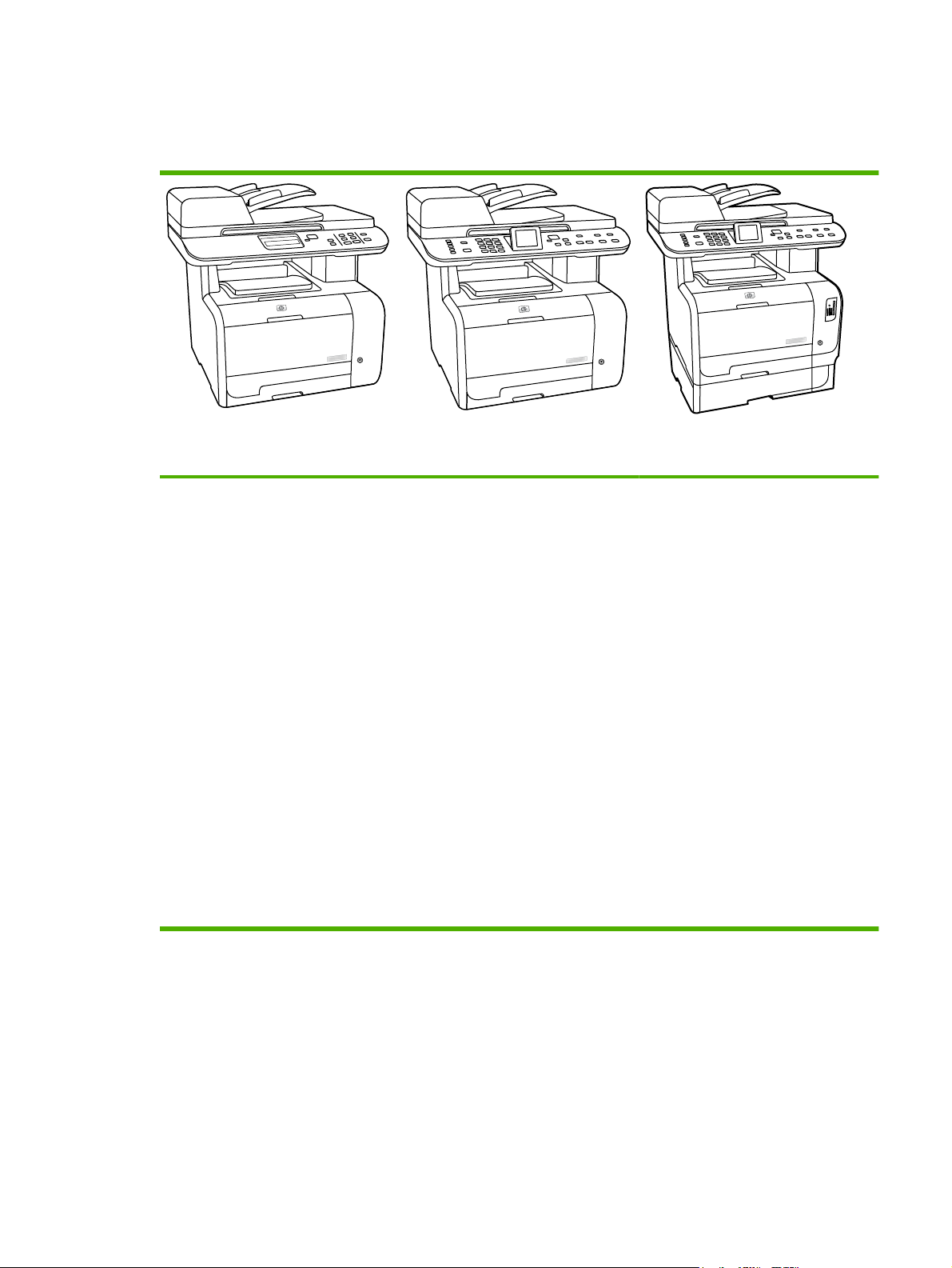
Product comparison
The product is available in the following configurations.
HP Color LaserJet CM2320 MFP
Prints letter-size pages at speeds
●
up to 21 pages per minute (ppm)
and A4-size pages at speeds up to
19 ppm.
PCL 6 printer drivers.
●
Tray 1 holds up to 50 sheets of print
●
media or up to 10 envelopes.
Tray 2 holds up to 250 sheets of
●
print media.
Optional 250-sheet input tray
●
(Tray 3) available.
Hi-Speed USB 2.0 port and 10/100
●
Base-T network port.
160-MB random-access memory
●
(RAM).
Flatbed scanner and 50-page
●
automatic document feeder (ADF).
One available DIMM slot for
●
memory expansion (accepts 64 MB
and 128 MB DIMMS).
HP Color LaserJet CM2320 MFP Fax
Model
HP Color LaserJet CM2320 MFP, plus:
V.34 fax modem and 8-megabyte
●
(MB) flash fax-storage memory.
Two RJ-11 fax phone line ports
●
Color graphics display
●
HP Color LaserJet CM2320 MFP
Memory-Card Model
HP Color LaserJet CM2320 MFP Fax
Model, plus:
Automatic two-sided (duplex)
●
printing, fax receiving, and copying.
Four memory card slots
●
Additional 250-sheet input tray
●
(Tray 3) included.
ENWW Product comparison 3
Page 16

Product features
Performance
Print quality
Fax (HP LaserJet CM2320
Fax Model / CM2320
Memory-Card Model only)
Copy
Scan
Memory card slots (HP
Color LaserJet CM2320 MFP
Memory-Card Model only)
Networking
Prints up to 21 ppm (letter) or 19 ppm (A4).
●
1,200 dots per inch (dpi) with Image REt 2400 text and graphics.
●
Adjustable settings to optimize print quality.
●
The HP UltraPrecise print cartridge has a finer toner formulation that provides sharper text
●
and graphics.
Full-functionality fax capabilities with a V.34 fax; includes a phone book, fax/tel, and
●
delayed-fax features.
Includes ADF that allows faster, more efficient copy jobs with multiple-page documents.
●
The product provides 1,200 pixels per inch (ppi), 24-bit full-color scanning from letter/A4-
●
size scanner glass.
The product provides 300 ppi, 24-bit full-color scanning from the automatic document
●
feeder (ADF).
Includes an ADF that allows faster, more efficient scan jobs with multiple-page documents.
●
Supports a variety of memory cards. See the user guide for more information.
TCP/IP
●
IPv4
◦
Printer driver features
Interface connections
Economical printing
Supplies
Accessibility
IPv6
◦
Fast printing performance, built-in Intellifont and TrueType scaling technologies, and
●
advanced imaging capabilities are benefits of the PCL 6 printer language.
Hi-Speed USB 2.0 port.
●
10/100 Base-T ethernet network port (RJ-45).
●
RJ-11 fax/phone cable ports (HP LaserJet CM2320 Fax Model / CM2320 Memory-Card
●
Model only).
N-up printing (printing more than one page on a sheet).
●
Two-sided printing using the automatic duplexer.
●
A supplies status page that displays the amount of life remaining in the print cartridge.
●
No-shake cartridge design.
●
Authentication for HP print cartridges.
●
Enabled supplies-ordering capability.
●
Online user guide that is compatible with text screen-readers.
●
Print cartridges can be installed and removed by using one hand.
●
All doors and covers can be opened by using one hand.
●
4 Chapter 1 Product basics ENWW
Page 17

Product walkaround
Front view
1 Optional Tray 3 (standard on the HP Color LaserJet CM2320 MFP Memory-Card Model)
2 Tray 2
3 Tray 1
4 Print-cartridge door latch
5 Top (face-down) output bin
6 Control panel
7 Automatic document feeder (ADF) input tray
8 Automatic document feeder (ADF) output bin
9 Memory card slots (HP Color LaserJet CM2320 MFP Memory-Card Model only)
10 Power switch
ENWW Product walkaround 5
Page 18

Back view
11 Power connector
12 DIMM door (for adding additional memory)
13 Hi-Speed USB 2.0 port and network port.
14 Fax ports (HP LaserJet CM2320 Fax Model / CM2320 Memory-Card Model only)
15 Rear door for jam access
6 Chapter 1 Product basics ENWW
Page 19
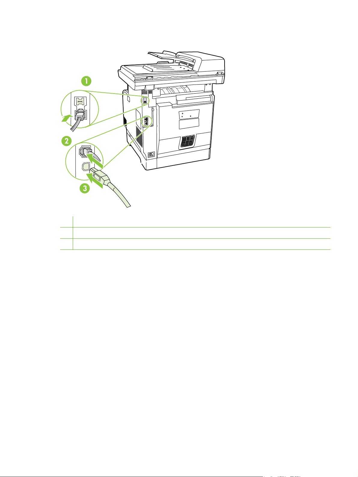
Interface ports
1 Fax ports (HP LaserJet CM2320 Fax Model / CM2320 Memory-Card Model only)
2 Network port
3 Hi-Speed USB 2.0 port
ENWW Product walkaround 7
Page 20

Supported operating systems
Supported operating systems for Windows
The product supports the following Windows operating systems:
Full software installation
Windows XP (32-bit)
●
Windows Vista (32-bit and 64-bit)
●
Print and scan driver
●
●
●
NOTE: The PCL 5 UPD and HP postscript level 3 emulation drivers are available only on the
HP support website:
www.hp.com/support/CM2320series.
Supported operating systems for Macintosh
The device supports the following Macintosh operating systems:
Mac OS X v10.3, v10.4, and later
●
NOTE: For Mac OS X v10.4 and later, PPC and Intel Core Processor Macs are supported.
Windows XP (64 bit)
Windows 2000
Windows 2003 Server (32-bit and 64-bit)
8 Chapter 1 Product basics ENWW
Page 21

Supported product software
Software included with the product
Software for Windows
Embedded Web server
The device is equipped with an embedded Web server, which provides access to information about
device and network activities. This information appears in a Web browser, such as Microsoft Internet
Explorer, Netscape Navigator, Apple Safari, or Firefox.
The embedded Web server resides on the device. It is not loaded on a network server.
The embedded Web server provides an interface to the device that anyone who has a networkconnected computer and a standard Web browser can use. No special software is installed or
configured, but you must have a supported Web browser on your computer. To gain access to the
embedded Web server, type the IP address for the device in the address line of the browser. (To find
the IP address, print a configuration page. For more information about printing a configuration page,
see
Information pages on page 50.)
For a complete explanation of the features and functionality of the embedded Web server, see
Embedded Web server on page 62.
ENWW Supported product software 9
Page 22

HP ToolboxFX
HP ToolboxFX software is a program that you can use for the following tasks:
●
●
●
●
●
●
●
You can view HP ToolboxFX software when the product is directly connected to your computer or when
it is connected to a network.
Check the product status
Check the supplies status and use HP SureSupply to shop online for supplies
Set up alerts
View product usage reports
View product documentation
Gain access to troubleshooting and maintenance tools
Use HP Proactive Support to routinely scan your printing system and to prevent potential problems.
HP Proactive Support can update software, firmware, and HP printer drivers.
Supported operating systems
Supported browsers
To download HP ToolboxFX software , go to www.hp.com/go/easyprintercare. This Web site also
provides updated information about supported browsers and a list of HP products that support
HP ToolboxFX software.
For more information about using HP ToolboxFX software, see
Software for Macintosh
Embedded Web server
The product is equipped with an embedded Web server, which provides access to information about
product and network activities. This information appears in a Web browser, such as Netscape Navigator,
Apple Safari, or Firefox.
The embedded Web server resides on the product. It is available on network and direct-connected
devices.
The embedded Web server provides an interface to the product that anyone who has a standard Web
browser can use. No special software is installed or configured, but you must have a supported Web
browser on your computer. To gain access to the embedded Web server, click Maintain Device in
HP Director.
Microsoft Windows XP, Service Pack 2 (Home and
●
Professional editions)
Microsoft Windows Vista™
●
Microsoft Internet Explorer 6.0 or 7.0
●
View the HP ToolboxFX on page 52.
For a complete explanation of the features and functionality of the embedded Web server, see
Embedded Web server on page 62.
10 Chapter 1 Product basics ENWW
Page 23

Supported printer drivers
Supported printer drivers for Windows
PCL 5 UPD
●
PCL 6
●
HP postscript level 3 UPD
●
The printer drivers include online Help that has instructions for common printing tasks and also describes
the buttons, checkboxes, and drop-down lists that are in the printer driver.
NOTE: The versions of PCL 5 and HP postscript level 3 emulation that are used in this product are
identical to the PCL 5 and HP postscript level 3 emulation that are used in the HP Universal Print Driver
(UPD) for Windows. It installs and operates in the same manner as previous versions of PCL 5 and
HP postscript level 3 emulation, and it does not require any special configuration.
For more information about the UPD, see
HP Universal Print Driver (UPD)
The HP Universal Print Driver (UPD) for Windows is a single driver that gives you instant access to
virtually any HP LaserJet product, from any location, without downloading separate drivers. It is built on
proven HP print driver technology and has been tested thoroughly and used with many software
programs. It is a powerful solution that performs consistently over time.
The HP UPD communicates directly with each HP product, gathers configuration information, and then
customizes the user interface to show the product’s unique, available features. It automatically enables
features that are available for the product, such as two-sided printing and stapling, so you do not need
to enable them manually.
For more information, go to
UPD installation modes
Traditional mode
Dynamic mode
www.hp.com/
www.hp.com/
go/upd.
go/upd.
Use this mode if you are installing the driver from a CD for a single computer.
●
When installed with this mode, UPD operates like traditional printer drivers.
●
If you use this mode, you must install UPD separately for each computer.
●
Use this mode if you are installing the driver for a mobile computer, so you can
●
discover and print to HP products in any location.
Use this mode if you are installing UPD for a workgroup.
●
To use this mode, download UPD from the Internet. See
●
upd.
www.hp.com/
go/
Supported printer drivers for Macintosh
The HP installer provides PostScript® Printer Description (PPD) files, Printer Dialog Extensions (PDEs),
and the HP Printer Utility for use with Macintosh computers.
The PPDs, in combination with the Apple PostScript printer drivers, provide access to device features.
Use the Apple PostScript printer driver that comes with the computer.
ENWW Supported product software 11
Page 24

Software for other operating systems
OS Software
UNIX For HP-UX and Solaris networks, go to www.hp.com/go/LJCM2320_software to download
Linux For information, go to www.hp.com/go/linuxprinting.
the HP Jetdirect printer installer for UNIX.
12 Chapter 1 Product basics ENWW
Page 25

System requirements
The product has the following minimum software and hardware requirements.
Windows XP Windows Vista Windows 2000 and Windows
Pentium II processor
●
(Pentium III or higher
recommended)
128 MB RAM
●
250 MB available hard disk
●
space
SVGA 800 x 600 monitor
●
with 16-bit color
Internet Explorer 6.0 or
●
higher (full installation)
USB port
●
CD-ROM drive
●
1 GHz processor
●
512 MB RAM
●
250 MB available hard disk
●
space
SVGA 800 x 600 monitor
●
with 16-bit color
Internet Explorer 6.0 or
●
higher (full installation)
USB port
●
CD-ROM drive
●
Server 2003
Pentium II processor or
●
greater
64 MB RAM
●
50 MB available hard disk
●
space
SVGA 800 x 600 monitor
●
with 16-bit color (print driver,
scan driver only)
USB port
●
CD-ROM drive
●
Mac OS X v10.3 and later
PowerPC G3, G4, or G5
●
processor, or Intel Core
processor
80 MB RAM
●
30 MB available hard disk
●
space
USB port
●
CD-ROM drive
●
Safari or Firefox browser
●
ENWW System requirements 13
Page 26

Connectivity
Supported network protocols
The product supports the TCP/IP network protocol. It is the most widely used and accepted networking
protocol. Many networking services utilize this protocol. This product also supports IPv4 and IPv6. The
following tables list the networking services/protocols that are supported on the product.
Table 1-2 Printing
Service name Description
port9100 (Direct Mode) Printing service
Line printer daemon (LPD) Printing service
Table 1-3 Network product discovery
Service name Description
SLP (Service Location Protocol) Device Discovery Protocol, used to help find and configure
network devices. Used primarily by Microsoft-based software
programs.
mDNS (multicast Domain Name Service - also known as
“Rendezvous” or “Bonjour”)
ws-discover Used by Microsoft-based software programs
LLMNR Used when DNS services are not available
Device Discovery Protocol, used to help find and configure
network devices. Used primarily by Apple Macintosh-based
software programs.
Table 1-4 Messaging and management
Service name Description
HTTP (hypertext transfer protocol) Allows Web browsers to communicate with embedded Web
EWS (embedded Web server) Allows a user to manage the product through a Web browser.
SNMP (simple network management protocol) Used by network programs for product management. SNMP
server.
V1 and standard MIB-II (Management Information Base)
objects are supported.
Table 1-5 IP addressing
Service name Description
DHCP (dynamic host configuration protocol), IPv4, and IPv6 For Automatic IP address assignment. DHCP server provides
the product with an IP address. Generally requires no user
intervention for product to obtain IP address from a DHCP
server.
14 Chapter 1 Product basics ENWW
Page 27

Table 1-5 IP addressing (continued)
Service name Description
BOOTP (bootstrap protocol) For Automatic IP address assignment. BOOTP server
provides the product with an IP address. Requires
administrator to input the product MAC hardware address on
BOOTP server in order for product to obtain an IP address from
that server.
Auto IP For Automatic IP address assignment. If neither a DHCP
server nor a BOOTP server is present, this service allows the
product to generate a unique IP address.
ENWW Connectivity 15
Page 28

16 Chapter 1 Product basics ENWW
Page 29

2 Control panel
HP Color LaserJet CM2320 control panel
●
HP Color LaserJet CM2320 MFP Fax Model and HP Color LaserJet CM2320 MFP Memory-Card
●
Model control panel
Control-panel menus
●
ENWW 17
Page 30

HP Color LaserJet CM2320 control panel
1 Liquid Crystal Display
2 OK button and navigation arrows. Use these buttons to select and confirm menu choices.
Cancel button. Use this button to cancel the current menu selection.
Setup button. Access the main Setup menu.
Back button. Go back to the previous menu.
3 Copy Menu button. Access the Copy menu.
Start Copy Black button. Perform a black and white copy operation.
Start Copy Color button. Perform a color copy operation.
4 Scan Menu button. Access the scan menu.
Start Scan button. Perform a scan operation.
18 Chapter 2 Control panel ENWW
Page 31

HP Color LaserJet CM2320 MFP Fax Model and HP Color
LaserJet CM2320 MFP Memory-Card Model control panel
4
.
.
1 Speed dials. 4 speed dial buttons and one shift button to support up to 8 speed dials.
2 Fax Menu button. Access the fax menu.
Start Fax button. Initiate a fax from the control panel.
3 Alphanumeric buttons. Use the alphanumeric buttons to type data into the product control-panel display and dial
telephone numbers for faxing.
4 Color graphics display
5 OK button and navigation arrows. Use these buttons to select and confirm menu choices.
Cancel button. Use this button to cancel the current menu selection.
Setup button. Access the main Setup menu.
Back button. Go back to the previous menu.
6 Copy Menu button. Access the copy menu.
5
6
?
7
8
Start Copy Black button. Perform a black and white copy operation.
Start Copy Color button. Perform a color copy operation.
7 Scan Menu button. Access the scan menu.
Start Scan button. Perform a scan operation.
8 Email Menu button (HP Color LaserJet CM2320 MFP Fax Model only). Access the e-mail menu.
Start Email button (HP Color LaserJet CM2320 MFP Fax Model only). Start a scan to e-mail.
Photo Menu button (HP Color LaserJet CM2320 MFP Memory-Card Model only). Access the photo menu.
Start Photo button (HP Color LaserJet CM2320 MFP Memory-Card Model only). Print the selected photos from the
memory card.
ENWW HP Color LaserJet CM2320 MFP Fax Model and HP Color LaserJet CM2320 MFP Memory-Card
Model control panel
19
Page 32

Control-panel menus
Use the control-panel menus
To gain access to the control-panel menus, use the following steps.
1.
Press Setup
.
NOTE: To access the function-specific menus press Fax Menu, Copy Menu, Scan Menu, or
Photo Menu.
2. Use the arrow buttons to navigate the listings.
Press OK to select the appropriate option.
●
Press Cancel to cancel an action or return to the Ready state.
●
Control-panel Setup menu
These sub menus are available from the control-panel main Setup menu:
Use the Copy setup menu to configure basic copy default settings such as contrast, collation, or
●
the number of copies printed.
Use the Reports menu to print reports that provide information about the product.
●
Use the Fax setup (HP LaserJet CM2320 Fax Model / CM2320 Memory-Card Model only) menu
●
to configure the fax phone book, the outgoing and incoming fax options, and the basic settings for
all faxes.
Use the Photo setup (HP Color LaserJet CM2320 MFP Memory-Card Model only) menu to
●
configure the basic settings for printing photos from a memory card.
Use the System setup menu to establish basic product settings such as language, print quality,
●
or volume levels.
Use the Service menu to restore default settings, clean the product, and activate special modes
●
that affect print output.
Use the Network configuration menu to configure network settings such as TCP/IP configuration.
●
NOTE: To print a detailed list of the entire control-panel menu and its structure, print a menu map.
See
Information pages on page 50.
Table 2-1 Copy setup menu
Menu item Sub-menu item Description
Default Optimize Auto Select
Mixed
Printed Picture
Photograph
Text
Default lighter/darker Sets the default contrast option.
Sets the default copy quality.
20 Chapter 2 Control panel ENWW
Page 33

Table 2-1 Copy setup menu (continued)
Menu item Sub-menu item Description
Default Collation On
Off
Default number of
copies
Default Reduce/Enlarge Original=100%
Default Tray Select Auto Select
(Range: 1-99) Sets the default number of copies.
Legal to Letter=78%
Legal to A4=83%
A4 to Letter=94%
Letter to A4=97%
Full Page=91%
Fit to page
2 pages per sheet
4 pages per sheet
Custom: 25 to 400%
Tray 1
Sets the default collation option.
Sets the default percentage to reduce or enlarge a copied
document.
Sets the default input paper tray.
Tray 2
Tray 3 (if the tray is installed)
Default 2-Sided
(memory-card models
only)
Default Copy Draft On
Default Multi-page On
1 to 1 sided
1 to 2 sided
2 to 2 sided
2 to 1 sided
Off
Off
Sets the default input scan format and the default output
format.
Sets the default draft mode option.
Sets the default multi-page flatbed copy option.
ENWW Control-panel menus 21
Page 34

Table 2-1 Copy setup menu (continued)
Menu item Sub-menu item Description
Advanced Color Copy Enables or disables the color copy button.
Lightness The default light/dark setting for copies. Possible values
range from 1 to 11 with 6 being the default (no change) value.
Contrast The default contrast setting for copies. Possible values
Sharpen The default sharpen setting for copies. Possible values
Background Removal The default background removal setting for copies. Possible
Color Balance The default color balance setting for copies. Possible values
Grayness The default grayness setting for copies. Possible values
Restore defaults Sets all customized copy settings to the factory default
range from 1 to 11 with 6 being the default (no change) value.
range from 1 to 11 with 6 being the default (no change) value.
values range from 1 to 11 with 6 being the default (no
change) value.
range from 1 to 11 with 6 being the default (no change) value.
Values can be set for each of the following settings:
Red
●
Green
●
Blue
●
range from 1 to 11 with 6 being the default (no change) value.
values.
Table 2-2 Reports menu
Menu Item Description
Demo page Prints a page that demonstrates print quality.
Menu structure Prints a control-panel menu layout map.
Configuration report Prints a list of all the product settings. Includes network information when the product is
Supplies status page Prints the print-cartridge status. Includes the following information:
Network report Displays status for:
Usage page Displays the number of pages printed, faxed, copied, and scanned by the product.
PCL font list Prints a list of all installed PCL 5 fonts.
connected to the network.
Approximate pages remaining
●
Serial number
●
Number of pages printed
●
Network hardware configuration
●
Enabled features
●
TCP/IP and SNMP information
●
Network statistics
●
22 Chapter 2 Control panel ENWW
Page 35

Table 2-2 Reports menu (continued)
Menu Item Description
PS font list Prints a list of all installed PS fonts.
PCL6 font list Prints a list of all installed PCL 6 fonts.
Color usage log Prints out information about the color toner usage
Service page Prints out diagnostic information about calibration and color quality
Table 2-3 Photo setup menu
Menu Item Sub-menu item Sub-menu item Description
Default image
Size
Default lighter/
darker
Default number of
copies
Default output
color
Restore defaults Restore the factory default settings for photo setup
(List of available
photo image sizes)
The default light/dark setting for photos. Possible values
The default number of copies setting for photos. Possible
Color
Black & white
The default image size for photos
range from 1 to 11 with 6 being the default (no change)
value.
values range from 1 to 99.
Specify the default output for photos.
Table 2-4 Fax setup menu (fax models only)
Menu Item Sub-menu item Sub-menu item Description
Fax Set-up Utility Utility for configuring the fax settings. Follow the on-screen
prompts and select the appropriate response for each
question using the arrow keys.
ENWW Control-panel menus 23
Page 36

Table 2-4 Fax setup menu (fax models only) (continued)
Menu Item Sub-menu item Sub-menu item Description
Basic setup Time/Date (Settings for time
format, current
time, date format,
and current date.)
Fax Header Your fax number
Company name
Answer mode Automatic
TAM
Fax/Tel
Manual
Sets the time and date setting for the product.
Sets the identifying information that is sent to the receiving
product.
Sets the type of answer mode. The following options are
available:
Automatic: The product automatically answers an
●
incoming call on the configured number of rings.
TAM: A telephone answering machine (TAM) is
●
attached to the Aux phone port of the product. The
product will not pick up any incoming call, but only listen
for fax tones after the answering machine has picked
up the call.
Fax/Tel: The product must automatically pick up the
●
call and determine if the call is a voice or fax call. If the
call is a fax call, the product handles the call as usual.
If the call is a voice call, an audible synthesized ring is
generated to alert the user of an incoming voice call.
Manual : The user must press the Start Fax button or
●
use an extension phone to make the product answer
the incoming call.
Rings to answer (Range of 1-9) Sets the number of rings that must occur before the fax
modem answers.
Distinctive Ring All Rings
Single
Double
Triple
Double and Triple
Dial Prefix On
Off
Allows a user to have two or three phone numbers on a
single line, each with a different ring pattern (on a phone
system with distinctive-ring service).
All Rings: The product answers any calls that come
●
through the telephone line.
Single: The product answers any calls that produce a
●
single-ring pattern.
Double: The product answers any calls that produce a
●
double-ring pattern.
Triple: The product answers any calls that produce a
●
triple-ring pattern.
Double and Triple: The product answers any calls that
●
produce a double-ring or triple-ring pattern.
Specifies a prefix number that must be dialed when sending
faxes from the product.
24 Chapter 2 Control panel ENWW
Page 37

Table 2-4 Fax setup menu (fax models only) (continued)
Menu Item Sub-menu item Sub-menu item Description
Advanced setup Default Fax
Resolution
Default lighter/
darker
Fit to page On
Default glass size Letter
Dialing Mode Tone
Redial if busy On
Redial if no answer On
Standard
Fine
Superfine
Photo
Sets the darkness of outgoing faxes.
Off
A4
Pulse
Off
Off
Sets the resolution for sent documents. Higher resolution
images have more dots per inch (dpi), so they show more
detail. Lower resolution images have fewer dots per inch and
show less detail, but the file size is smaller.
Shrinks faxes that are larger than Letter-size or A4-size so
that they can fit onto a Letter-size or A4-size page. If this
feature is set to Off, faxes larger than Letter or A4 will print
on multiple pages.
Sets the default paper size for documents being scanned
from the flatbed scanner.
Sets whether the product should use tone or pulse dialing.
Sets whether or not the product should attempt to redial if
the line is busy.
Sets whether the product should attempt to dial if the
recipient fax number does not answer.
Redial Comm.
Error
On
Off
Sets whether the product should attempt to redial the
recipient fax number if a communication error occurs.
ENWW Control-panel menus 25
Page 38

Table 2-4 Fax setup menu (fax models only) (continued)
Menu Item Sub-menu item Sub-menu item Description
Advanced setup Detect dial tone On
Off
Billing codes On
Off
Extension Phone On
Off
Stamp faxes On
Off
Private receive On
Off
Fax Number
Confirmation
On
Off
Sets whether the product should check for a dial tone before
sending a fax.
Enables the use of billing codes when set to On. A prompt
will appear that asks you to enter the billing code for an
outgoing fax.
When this feature is enabled, the user can press the 1-2-3
buttons on the extension phone to cause the product to
answer an incoming fax call.
Sets product to add the date, time, sender's phone number,
and page number to each page of the faxes that this product
receives.
Setting Private receive to On requires the user to have set
a password in product security. After the password is set,
the following options are set:
Private receive is turned on.
●
All old faxes are deleted from memory.
●
Fax forwarding set to Off and is not allowed to be
●
changed.
All incoming faxes are stored in memory.
●
Verify that a fax number is valid by entering it a second time.
Allow Fax Reprint On
Off
Fax/Tel Ring Time 20
30
40
70
Print Duplex
(duplex models
only)
Fax Speed Fast(V.34)
On
Off
Medium(V.17)
Slow(V.29)
Sets whether all received faxes stored in available memory
can be reprinted.
Sets when the product should stop sounding the Fax/Tel
audible ring to notify the user of an incoming voice call.
Sets whether all received faxes are printed using both sides
of the paper.
Increases or decreases the allowed fax communication
speed.
Table 2-5 System setup menu
Menu Item Sub-menu item Sub-menu item Description
Language (List of available
control-panel
display languages.)
Sets the language in which the control panel displays
messages and product reports.
26 Chapter 2 Control panel ENWW
Page 39

Table 2-5 System setup menu (continued)
Menu Item Sub-menu item Sub-menu item Description
Paper setup Default paper size Letter
A4
Legal
Default paper type Lists available
media types.
Tray 1 Paper type
Paper size
Paper out action Wait forever
Cancel
Override
Sets the size for printing internal reports or any print job that
does not specify a size.
Sets the type for printing internal reports or any print job that
does not specify a type.
Sets the default size and type for Tray 1.
Determines how the product reacts when a print job requires
a media size or type that is unavailable or when a specified
tray is empty.
Select Wait forever to make the product wait until the
●
correct media is loaded.
Select Override to print on a different size paper after
●
a specified delay.
Select Cancel to automatically cancel the print job after
●
a specified delay.
If either Override or Cancel is chosen, the control
●
panel prompts for the number of seconds to delay. Use
the arrow keys to either decrease the time or increase
the time up to 3,600 seconds.
Print quality Calibrate color Calibrate now
After power on
Adjust Alignment
(memory-card
models only)
Cartridge low
threshold
Replace Supplies Stop at out
Color Supply Out Stop Printing
Print Test Page Print out a tray-specific sheet of instructions and a test page
Adjust Tray 1 After printing the test page, use the options in the Adjust
(Range of 1-20) Sets the percentage at which the control panel generates a
Override out
Continue Black
Perform a Color Pane Registration (CPR) and density
calibration. Select Calibrate now to perform an immediate
calibration. Select After power on to specify the minutes/
hours the product should wait after power on to perform an
automatic calibration (the default is 15 minutes).
low-toner message.
Sets how the product reacts when it detects that the print
cartridge is out.
Sets how the product should react when it detects that a
color cartridge is empty. Select Stop Printing to stop all
printing until the cartridge is replaced, or select Continue
Black to continue printing in black monochrome mode.
with a border that can be used to estimate the adjustment
needed to center the printed image on the page.
Tray 1 menu to calibrate the tray. The following settings can
be adjusted for Tray 1:
X1 Shift
●
Y Shift
●
ENWW Control-panel menus 27
Page 40

Table 2-5 System setup menu (continued)
Menu Item Sub-menu item Sub-menu item Description
Volume Settings
(memory-card
models only)
Time/Date (Settings for time
Product security On
Courier font Regular
Alarm volume Soft
Ring volume
Key-press volume
Phone line volume
format, current time,
date format, and
current date.)
Off
Dark
Medium
Loud
Off
Sets the time and date setting for the product.
Sets the product-security feature. When the setting is set to
Sets Courier font values.
Sets the volume levels for the product.
On, you must set a personal identification number (PIN).
Table 2-6 Service menu
Menu item Sub-menu item Sub-menu item Description
Fax Service Clear saved faxes Clear all faxes in memory.
These include any received
faxes (including non-printed,
non-sent PC upload, and nonforwarded faxes), unsent faxes
(including delayed faxes), and
any printed faxes that are still in
memory. Deleted faxes cannot
be recovered. For each deleted
item, the fax activity log is
updated.
Run Fax Test Perform a fax test to verify that
Print T.30 trace Now
Never
If error
At end of call
Error correction On
Off
Fax Service Log The fax service log prints out
Cleaning mode Cleans the product when
the phone cord is plugged in
the correct outlet and that there
is a signal on the phone line. A
fax test report is printed
indicating the results.
Prints or schedules a report
that is used to troubleshoot fax
transmission issues.
The error correction mode
allows the sending device to retransmit data if it detects an
error signal. The default setting
is on.
the last 40 entries in the fax log.
specks or other marks appear
28 Chapter 2 Control panel ENWW
Page 41

Table 2-6 Service menu (continued)
Menu item Sub-menu item Sub-menu item Description
on printed output. The cleaning
process removes dust and
excess toner from the paper
path.
When selected, the product
prompts you to load plain Letter
or A4 paper in Tray 1. Press
OK to begin the cleaning
process. Wait until the process
completes. Discard the page
that prints.
1 minute Off
1 minute
15 minutes
30 minutes
1 hour
2 hours
4 hours
USB speed High
Full
Less paper curl On
Off
Archive print On
Off
Specify the amount of idle time
before the product enters sleep
mode.
Sets the USB speed.
When printed pages are
consistently curled, this option
sets the product to a mode that
reduces curl.
The default setting is Off.
When printing pages that will
be stored for a long time, this
option sets the product to a
mode that reduces toner
smearing and dusting.
The default setting is Off.
Restore defaults Sets all customized settings to
the factory default values.
Table 2-7 Network configuration menu
Menu item Sub-menu item Description
TCP/IP configuration Automatic
Manual
Automatic automatically configures all the TCP/IP settings via
DHCP, BootP or AutoIP.
Manual requires you to manually configure the IP address, subnet
mask, and default gateway.
The control panel prompts you to specify values for each address
section. Use the arrow buttons to increase or decrease the value.
Press OK to accept the value and move the cursor to the next field.
ENWW Control-panel menus 29
Page 42

Table 2-7 Network configuration menu (continued)
Menu item Sub-menu item Description
As each address is completed, the product prompts for address
confirmation before moving to the next one. After all three
addresses are set, the product automatically restarts.
Memory Card (memorycard products only)
Auto crossover On
Network services IPv4
Show IP address Yes
Link speed Automatic (Default)
Restore defaults Resets all network configurations to their factory defaults.
On
Off
Off
IPv6
DHCPv6
No
10T Full
10T Half
100TX Full
100TX Half
Enables or disables the use of the memory-card slots.
Enable or disable the use of a standard 10/100 network cable when
the product is directly connected to a PC.
Sets whether the product will use either IPv4, IPv6, or DHCPv6
protocol.
Sets whether the product displays the IP address on the control
panel.
Sets the link speed manually if needed.
After setting the link speed, the product automatically restarts.
Function specific menus
The product features function-specific menus for faxing, copying, scanning, and managing photos on a
memory card. To access these menus, press the Fax Menu, Copy Menu, Scan Menu, or Photo Menu
buttons respectively.
These are the features supported by the function specific menus.
Use the Fax menu to perform basic fax functions such as sending a fax or editing the phone book,
●
reprinting faxes that were previously printed, or printing faxes that are stored in memory.
Use the Copy menu to access basic copy functions and customize the copy output.
●
Use the Scan menu to display a list of preconfigured folders and e-mail destinations to select from.
●
Use the Email menu (HP Color LaserJet CM2320 MFP Fax Model only) to send e-mail.
●
Use the Photo menu (HP Color LaserJet CM2320 MFP Memory-Card Model only) to display a list
●
of photo options for a valid inserted memory card.
30 Chapter 2 Control panel ENWW
Page 43

Table 2-8 Fax Menu
Menu item Sub-menu item Sub-menu item Description
Send Send a fax Send a fax. On screen
Redial Redial the last fax number
Send fax later Allows a fax to be sent at a
Fax Job status Displays pending fax jobs,
Fax Resolution Standard
Fine
Superfine
Photo
Receive Print faxes Prints stored faxes when the
Block junk faxes Add number
Delete number
Delete All Entries
Junk Fax list
prompts guide the process.
and resend.
later time and date.
and allows you to cancel
pending fax jobs.
Temporarily change the
resolution of outgoing faxes.
The resolution resets to
default after 2 minutes of idle
fax scan time.
private-receive feature is on.
This menu item appears only
when the private-receive
feature is turned on.
Modifies the junk fax list. The
junk fax list can contain up to
30 numbers. When the
product receives a call from
one of the junk fax numbers, it
deletes the incoming fax. It
also logs the junk fax in the
activity log along with jobaccounting information.
Reprint faxes Prints the received faxes
Forward fax On
Off
Polling receive Allows the product to call
stored in available memory.
Sets product to send all
received faxes to another fax
machine.
another fax machine that has
polling send enabled.
ENWW Control-panel menus 31
Page 44

Table 2-8 Fax Menu (continued)
Menu item Sub-menu item Sub-menu item Description
Phone Book Select an entry Select an individual or group
dial entry for faxing.
Individual Setup Edits the fax phone book
Group setup
Delete entry Delete a specific phone book
entry.
Delete All Entries Delete all entries in the phone
Phone Book report Print a list of all the individual
speed dials and group-dial
entries. The product supports
up to 120 phone book entries,
which can be either individual
or group entries.
book
and group dial entries in the
phone book.
32 Chapter 2 Control panel ENWW
Page 45

Table 2-8 Fax Menu (continued)
Menu item Sub-menu item Sub-menu item Description
Fax Reports Fax Confirmation Never
Every fax
Send fax only
Receive fax
Include first page On
Off
Fax Error Report Every error
Send Error
Receive Error
Never
Last Call Report Prints a detailed report of the
Fax Activity log Print log now
Auto Log Print
Sets whether or not the
product prints a confirmation
report after a successful
sending or receiving job.
Sets whether or not the
product includes a thumbnail
image of the first page of the
fax on the report.
Sets whether or not the
product prints a report after a
failed sending or receiving
job.
last fax operation, either sent
or received.
Print log now: Prints a list of
the faxes that have been sent
from or received by this
product.
Auto Log Print: Select On to
automatically print a report
after every fax job. Select Off
to turn off the automatic print
feature.
Phone Book report Prints a list of the speed dials
that have been set up for this
product.
Junk Fax list Prints a list of phone numbers
that are blocked from sending
faxes to this product.
Billing report Prints a list of billing codes
All fax reports Prints all fax-related reports.
that have been used for
outgoing faxes. This report
shows how many sent faxes
were billed to each code. This
menu item appears only when
the billing codes feature is
turned on.
Table 2-9 Photo Menu
Menu item Sub-menu item Sub-menu item Description
View View photos on the memory
card. Use the arrow buttons to
navigate through the photos.
ENWW Control-panel menus 33
Page 46

Table 2-9 Photo Menu (continued)
Menu item Sub-menu item Sub-menu item Description
Easy Print Individual photo
All photos (#-#)
A range of photos
Custom
Thumbnail Fast
Best
Options Proof Sheet Print proof sheet
Current Settings Select image size
Print photos quickly from the
Print thumbnails of photos
Scan proof sheet
Select paper size
Select paper type
Number of copies
Output Color
memory card by selecting the
numbers of the photos you
want to print.
from the memory card (30 per
page).
Print a proof sheet or scan a
proof sheet. The proof sheet
is a page of thumbnails (20
per page) generated from a
valid memory card. A marked
proof sheet can then be
scanned and the selected
images are printed at full size.
Adjust the default photo
settings for image size, paper
size, paper type, number of
copies, and output color (color
or black and white).
Rotate Photo Rotate a photo stored on a
Slideshow View a slideshow of the
Table 2-10 Copy Menu
Menu item Sub-menu item Description
Copies (1–99) Specify the number of copies
Size Original=100%
Legal to Letter=78%
Legal to A4=83%
A4 to Letter=94%
Letter to A4=97%
Full Page=91%
Fit to page
2 pages per sheet
4 pages per sheet
Specify the size of the copy.
memory card.
photos on a memory card.
Custom: 25 to 400%
34 Chapter 2 Control panel ENWW
Page 47

Table 2-10 Copy Menu (continued)
Menu item Sub-menu item Description
Light/Dark Specify the contrast of the copy.
Options Optimize Select settings to optimize the copy print quality.
Copy Paper Specify the paper type for the copies.
Multi-Page Copy Copy multiple pages.
Copy Collation Specify the copy collation
Tray Select Select the tray to copy from.
Copy 2-Sided Copy multiple sides and print duplex.
Copy Draft Specify the print quality for copies.
Image Adjustment Lightness
Contrast
Sharpen
Background
Color Balance
Grayness
Adjust the settings for image quality in a copy.
ENWW Control-panel menus 35
Page 48

36 Chapter 2 Control panel ENWW
Page 49

3 Paper and print media
Understand paper and print media use
●
Supported paper and print media sizes
●
Supported paper types and tray capacity
●
Special paper or print media guidelines
●
Load paper and print media
●
Configure trays
●
ENWW 37
Page 50

Understand paper and print media use
This product supports a variety of paper and other print media in accordance with the guidelines in this
user guide. Paper or print media that does not meet these guidelines might cause the following problems:
Poor print quality
●
Increased jams
●
Premature wear on the product, requiring repair
●
For best results, use only HP-brand paper and print media designed for laser printers or multiuse. Do
not use paper or print media made for inkjet printers. Hewlett-Packard Company cannot recommend
the use of other brands of media because HP cannot control their quality.
It is possible for paper to meet all of the guidelines in this user guide and still not produce satisfactory
results. This might be the result of improper handling, unacceptable temperature and/or humidity levels,
or other variables over which Hewlett-Packard has no control.
CAUTION: Using paper or print media that does not meet Hewlett-Packard's specifications might
cause problems for the product, requiring repair. This repair is not covered by the Hewlett-Packard
warranty or service agreements.
38 Chapter 3 Paper and print media ENWW
Page 51

Supported paper and print media sizes
This product supports a number of paper sizes, and it adapts to various media.
NOTE: To obtain best print results, select the appropriate paper size and type in the print driver before
printing.
Table 3-1 Supported paper and print media sizes
Size Dimensions Tray 1 Trays 2 and 3
Letter 216 x 279 mm (8.5 x 11 inches)
Legal 216 x 356 mm (8.5 x 14 inches)
A4 210 x 297 mm (8.27 x 11.69 inches)
Executive 184 x 267 mm (7.24 x 10.51 inches)
A3 297 x 420 mm (11.69 x 16.54 inches)
A5 148 x 210 mm (5.83 x 8.27 inches)
A6 105 x 148 mm (4.13 x 5.83 inches)
B5 (JIS) 182 x 257 mm (7.17 x 10.12 inches)
16k 197 x 273 mm (7.75 x 10.75 inches)
16k 195 x 270 mm (7.7 x 10.6 inches)
16k 184 x 260 mm (7.25 x 10.25 inches)
8.5 x 13 216 x 330 mm (8.5 x 13 inches)
1
4 x 6
1
5 x 8
10 x 15 cm
Custom Tray 1: Minimum—76 x127 mm (3 x 5 inches);
1
These sizes are supported as custom sizes.
1
107 x 152 mm (4 x 6 inches)
127 x 203 mm (5 x 8 inches)
100 x 150 mm (3.9 x 5.9 inches)
Maximum—216 x 356 mm (8.5 x 14 inches)
Trays 2 and 3: Minimum—100 x 148 mm (3.9 x
5.83 inches); Maximum—216 x 356 mm (8.5 x
14 inches)
Table 3-2 Supported envelopes and postcards
Size Dimensions Tray 1 Trays 2 and 3
Envelope #10 105 x 241 mm (4.13 x 9.49 inches)
ENWW Supported paper and print media sizes 39
Page 52

Table 3-2 Supported envelopes and postcards (continued)
Size Dimensions Tray 1 Trays 2 and 3
Envelope DL 110 x 220 mm (4.33 x 8.66 inches)
Envelope C5 162 x 229 mm (6.93 x 9.84 inches)
Envelope B5 176 x 250 mm (6.7 x 9.8 inches)
Envelope Monarch 98 x 191 mm (3.9 x 7.5 inches)
Postcard 100 x 148 mm (3.94 x 5.83 inches)
Double postcard 148 x 200 mm (5.83 x 7.87 inches)
40 Chapter 3 Paper and print media ENWW
Page 53

Supported paper types and tray capacity
Media type Dimensions
Paper, including the
following types:
Plain
●
Minimum: 76 x 127 mm
(3 x 5 inches)
Maximum: 216 x 356 mm
1
(8.5 x 14 inches)
Letterhead
●
Color
●
Preprinted
●
Prepunched
●
Recycled
●
Thick paper Same as for paper
Cover paper Same as for paper
Glossy paper
Same as for paper
Photo paper
Weight Capacity
60 to 90 g/m2 (16 to 24 lb)
Tray 1: up to 50 sheets
Trays 2 and 3: up to 250
sheets of
2
75 g/m
Up to 200 g/m2 (53 lb)
Tray 1: single sheet only
Trays 2 and 3: up to
25 mm (0.98 inch) stack
height
Up to 200 g/m2 (53 lb)
Tray 1: single sheet only
Trays 2 and 3: up to
25 mm (.98 inch) stack
height
Up to 220 g/m2 (59 lb)
Tray 1: single sheet only
Trays 2 and 3: up to
25 mm (.98 inch) stack
height
2
(20 lb bond)
Paper orientation
Side to be printed on faceup, with the top edge at
the back of the tray
Side to be printed on faceup, with the top edge at
the back of the tray
Side to be printed on faceup, with the top edge at
the back of the tray
Side to be printed on faceup, with the top edge at
the back of the tray
Transparencies A4 or Letter Thickness: 0.12 to
0.13 mm (4.7 to 5.1 mils)
3
Labels
A4 or Letter Thickness: up to 0.23 mm
(9 mils)
Envelopes
Postcards or index cards 100 x 148 mm
●
●
●
●
●
COM 10
Monarch
DL
C5
B5
Up to 90 g/m2 (24 lb)
Tray 1: single sheet only Side to be printed on face-
(3.9 x 5.8 inches)
Tray 1: single sheet only
Trays 2 and 3: up to
25 mm (.98 inch) stack
height
Tray 1: single sheet only
Trays 2 and 3: up to
25 mm (.98 inch) stack
height
Tray 1: up to 10 envelopes
Trays 2 and 3: up to 30
envelopes
Side to be printed on faceup, with the top edge at
the back of the tray
Side to be printed on faceup, with the top edge at
the back of the tray
Side to be printed on faceup, with the stamp-end at
the back of the tray
up, with the top edge at
the back of the tray
ENWW Supported paper types and tray capacity 41
Page 54

Media type Dimensions
1
The product supports a wide range of standard and custom sizes of print media. Check the printer driver for supported sizes.
2
Capacity can vary depending on media weight and thickness, and environmental conditions.
3
Smoothness: 100 to 250 (Sheffield)
1
Weight Capacity
Trays 2 and 3: up to
25 mm (.98 inch) stack
height
Special paper or print media guidelines
This product supports printing on special media. Use the following guidelines to obtain satisfactory
results. When using special paper or print media, be sure to set the type and size in your print driver to
obtain the best print results.
CAUTION: HP LaserJet printers use fusers to bond dry toner particles to the paper in very precise
dots. HP laser paper is designed to withstand this extreme heat. Using inkjet paper not designed for this
technology could damage your printer.
Media type Do Do not
2
Paper orientation
Envelopes
Labels
Transparencies
Letterhead or preprinted forms
Heavy paper
Store envelopes flat.
●
Use envelopes where the seam
●
extends all the way to the corner of
the envelope.
Use peel-off adhesive strips that
●
are approved for use in laser
printers.
Use only labels that have no
●
exposed backing between them.
Use Labels that lie flat.
●
Use only full sheets of labels.
●
Use only transparencies that are
●
approved for use in laser printers.
Place transparencies on a flat
●
surface after removing them from
the product.
Use only letterhead or forms
●
approved for use in laser printers.
Use only heavy paper that is
●
approved for use in laser printers
and meets the weight specifications
for this product.
Do not use envelopes that are
●
wrinkled, nicked, stuck together, or
otherwise damaged.
Do not use envelopes that have
●
clasps, snaps, windows, or coated
linings.
Do not use self-stick adhesives or
●
other synthetic materials.
Do not use labels that have wrinkles
●
or bubbles, or are damaged.
Do not print partial sheets of labels.
●
Do not use transparent print media
●
not approved for laser printers.
Do not use raised or metallic
●
letterhead.
Do not use paper that is heavier
●
than the recommended media
specification for this product unless
it is HP paper that has been
approved for use in this product.
Glossy or coated paper
Use only glossy or coated paper
●
that is approved for use in laser
printers.
Do not use glossy or coated paper
●
designed for use in inkjet products.
42 Chapter 3 Paper and print media ENWW
Page 55

Load paper and print media
Load Tray 1
Tray 1 holds up to 50 sheets of 75 g/m2 (20 lb) media or five envelopes, ten transparencies, or ten cards.
You can use Tray 1 to print the first page on media different from the remainder of the document.
1. Open Tray 1.
2. If loading long sheets of media, pull out the extension tray.
3. If necessary, flip out the extension.
ENWW Load paper and print media 43
Page 56

4. Extend the paper guides fully (callout 1) and then load the media stack into Tray 1 (callout 2). Adjust
the paper guides to the size of the paper.
Load Tray 2 or 3
Tray 2 and optional Tray 3 hold up to 250 pages of 75 g/m2 (20 lb) paper, or fewer pages of heavier
media (25 mm (0.9 in) or less stack height). Load media with the top forward and the side to be printed
on facing up.
1. Pull the tray out of the product.
2. Slide open the paper length and width guides.
To load Legal-size paper, extend the tray by pressing and holding the extension tab while
●
pulling the front of the tray toward you.
NOTE: When it is loaded with Legal-size paper, the tray extends from the front of the product
approximately 64 mm (2.5 inches).
44 Chapter 3 Paper and print media ENWW
Page 57

3. Place the paper in the tray and make sure that it is flat at all four corners. Slide the paper length
and width guides so that they are against the stack of paper.
4. Push down on the paper to make sure that the paper stack is below the paper limit tabs on the side
of the tray.
5. Slide the tray into the product.
NOTE: When it is loaded with Legal-size paper, the tray extends from the front of the product
approximately 64 mm (2.5 inches).
Load originals for copying, scanning, or faxing
Automatic document feeder (ADF)
NOTE: The ADF capacity is up to 50 sheets of 80 g/m2 or 20 lb media.
CAUTION: To prevent damage to the product, do not use an original that contains correction tape,
correction fluid, paper clips, or staples. Also, do not load photographs, small originals, or fragile originals
into the ADF. Use the flatbed glass to scan these items.
1. Insert the top-end of the stack of originals into the ADF input tray, with the media stack face-up
and the first page to be copied or scanned on top of the stack.
If the media is longer than letter- or A4-sized paper, pull out the ADF input tray extension to support
the media.
ENWW Load paper and print media 45
Page 58

2. Slide the stack into the ADF until it does not move any farther.
Document loaded appears on the control-panel display.
3. Adjust the media guides until they are snug against the media.
Flatbed glass
NOTE: The maximum media size for flatbed copying is letter. Use the ADF for copying or scanning
media larger than letter.
1. Make sure that the automatic document feeder (ADF) contains no media.
2. Lift the flatbed scanner cover.
46 Chapter 3 Paper and print media ENWW
Page 59

3. Place the original document face-down on the flatbed glass with the upper-left corner of the
document at the corner indicated by the icon on the scanner.
4. Gently close the lid.
ENWW Load paper and print media 47
Page 60

Configure trays
When using one of the trays for specific size of paper, you can set the default size for the tray in
HP ToolboxFX or from the control panel. In HP ToolboxFX, select Paper handling, and then select the
size for the tray you want to set. When you select that size of paper for a print job in the print dialog, the
product automatically selects that tray for printing.
To set the default paper size or type from the control panel, complete the following steps.
1.
On the product control panel, press Setup
2. Use the arrow buttons to highlight System setup, and then press OK.
3. Use the arrow buttons to highlight Paper setup, and then press OK.
4. Use the arrow buttons to highlight the tray to be configured, and then press OK.
5. Use the arrow buttons to highlight either Paper type or Paper size, and then press OK.
6. Use the arrow buttons to highlight a default type or size for the tray, and then press OK.
.
48 Chapter 3 Paper and print media ENWW
Page 61

4 Manage and maintain the product
Information pages
●
HP ToolboxFX
●
Embedded Web server
●
Use HP Web Jetadmin software
●
Security features
●
Manage supplies
●
ENWW 49
Page 62

Information pages
Information pages reside within the product memory. These pages help diagnose and solve problems
with the product.
NOTE: If the product language was not correctly set during installation, you can set the language
manually so the information pages print in one of the supported languages. Change the language by
using the System setup menu on the control panel or the embedded Web server. See
on page 17.
Page description How to print the page
Control panel
Configuration page
Shows the current settings and product properties.
Supplies status page
Shows the remaining life of the HP print cartridge, the
approximate pages remaining, the number of pages printed,
and other supplies information.
PCL, PCL 6, or PS font list
Shows which fonts are currently installed in the device.
Demo page
Contains examples of text and graphics.
1.
On the product control panel, press Setup
2. Use the arrow buttons to select Reports, and then press
OK.
3. Use the arrow buttons to select Configuration report,
and then press OK.
A second page also prints (fax models only). On that page, the
Fax Settings section provides details about the product fax
settings.
1.
On the product control panel, press Setup
2. Use the arrow buttons to select Reports, and then press
OK.
3. Use the arrow buttons to select Supplies status, and
then press OK.
1.
On the product control panel, press Setup
2. Use the arrow buttons to select Reports, and then press
OK.
3. Use the arrow buttons to select PCL font list, PS font
list, or PCL6 font list, and then press OK.
1.
On the product control panel, press Setup
2. Use the arrow buttons to select Reports, and then press
OK.
.
.
.
.
3. Use the arrow buttons to select Demo page, and then
press OK.
Event log You can print the event log from HP ToolboxFX, the embedded
Usage page
Shows the number of one-sided (simplexed) or two-sided
(duplexed) pages, and the average percentage of coverage.
Web server, or HP Web Jetadmin. See
on page 52, Embedded Web server on page 62, or the Web
Jetadmin Help.
1.
On the product control panel, press Setup
2. Use the arrow buttons to select Reports, and then press
OK.
3. Use the arrow buttons to select Usage page, and then
press OK.
HP ToolboxFX
.
50 Chapter 4 Manage and maintain the product ENWW
Page 63

Page description How to print the page
Menu structure
Shows the control-panel menus.
Network report
Shows the product network settings.
Fax reports (fax models only) For information about fax logs and reports, see the user guide.
Color usage job log
Provides a summary of color usage.
Service page
Prints a service report.
1.
On the product control panel, press Setup
2. Use the arrow buttons to select Reports, and then press
OK.
3. Use the arrow buttons to select Menu structure, and then
press OK.
1.
On the product control panel, press Setup
2. Use the arrow buttons to select Reports, and then press
OK.
3. Use the arrow buttons to select Network report, and then
press OK.
1.
On the product control panel, press Setup
2. Use the arrow buttons to select Reports, and then press
OK.
3. Use the arrow buttons to select Color usage job log, and
then press OK.
1. On the product control panel, press Setup.
2. Use the arrow buttons to select Reports, and then press
OK.
.
.
.
Diagnostics page
Prints a diagnostics page pertaining to color calibration and
color quality.
3. Use the arrow buttons to select Service page, and then
press OK.
1.
On the product control panel, press Setup
2. Use the arrow buttons to select Reports, and then press
OK.
3. Use the arrow buttons to select Diagnostics page, and
then press OK.
.
ENWW Information pages 51
Page 64

HP ToolboxFX
HP ToolboxFX is a program that you can use to complete the following tasks:
Check the product status.
●
Configure the product settings.
●
Configure pop-up-alert messages.
●
View troubleshooting information.
●
View online documentation.
●
You can view HP ToolboxFX when the product is directly connected to your computer or is connected
to the network. You must perform a recommended software installation to use HP ToolboxFX.
NOTE: HP ToolboxFX is not supported for Windows Server 2003 or Macintosh operating systems. To
use HP ToolboxFX, you must have TCP/IP protocol installed on your computer.
You do not have to have Internet access to open and use HP ToolboxFX.
View the HP ToolboxFX
Open HP ToolboxFX in one of these ways:
Status
●
In the Windows system tray, double-click the HP ToolboxFX icon (
On the Windows Start menu, click Programs (or All Programs in Windows XP and Vista), click
●
HP, click HP Color LaserJet CM2320 MFP Series, and then click HP ToolboxFX.
The Status folder contains links to the following main pages:
Device status. This page indicates product conditions such as a jam or an empty tray. After you
●
correct a problem, click Refresh status to update the product status.
Supplies status. View details such as the approximate percent of toner remaining in the print
●
cartridge and the number of pages that have been printed with the current print cartridge. This page
also has links for ordering supplies and for finding recycling information.
Device configuration. View a detailed description of the current product configuration, including
●
the amount of memory installed and whether optional trays are installed.
Network summary. View a detailed description of the current network configuration, including the
●
IP address and network status.
Print info pages. Print the configuration page and other information pages, such as the supplies
●
status page. See
Color usage job log. View color usage information for the product.
●
Information pages on page 50.
).
Event log. View a history of product errors. The most recent error is listed first.
●
52 Chapter 4 Manage and maintain the product ENWW
Page 65

Event log
The event log is a four-column table where the product events are logged for your reference. The log
contains codes that correspond to the error messages that appear on the product control-panel display.
The number in the Page Count column specifies the total number of pages that the product had printed
when the error occurred. The event log also contains a brief description of the error. For more information
about error messages, see
Alerts
The HP ToolboxFX Alerts tab contains links to the following main pages:
Set up Status Alerts. Set up the product to send you pop-up alerts for certain events, such as low
●
toner levels.
Set up E-mail Alerts. Set up the product to send you e-mail alert messages for certain events,
●
such as low toner levels.
Set up status alerts
Use HP ToolboxFX to set up the product so that it issues pop-up alerts to your computer when certain
events occur. Events that trigger alerts include jams, low levels of toner in HP print cartridges, non-HP
print cartridge in use, empty input trays, and specific error messages.
Select the pop-up format, the tray icon format, or both for the alerts. The pop-up alerts only appear when
the product is printing from the computer on which you set up the alerts.
Control-panel messages on page 257.
Change the Cartridge low threshold setting, which sets the toner level that causes a low toner alert,
in System Setup on the System Settings tab.
NOTE: You must click Apply before the changes take effect.
Set up e-mail alerts
Use this to configure up to two e-mail addresses to receive alert messages when certain events occur.
You can specify different events for each e-mail address. Use the information for the e-mail server that
will send out the e-mail alert messages for the product.
NOTE: You can only configure e-mail alerts to be sent from a server that does not require user
authentication. If your e-mail server requires you to log in with a username and password, you cannot
enable e-mail alerts.
NOTE: You must click Apply before your changes take effect.
Product information
The Product information folder contains links to the following page:
Demonstration Pages. Print pages that show the color print quality potential and overall print
●
characteristics of the product.
ENWW HP ToolboxFX 53
Page 66

Fax
Use the HP ToolboxFX Fax tab to perform fax tasks from your computer. The Fax tab contains links to
the following main pages:
●
●
●
●
●
●
Fax Receive
The following options are available when receiving a fax:
●
●
Fax Receive. Set the fax receive mode.
Fax Phone Book. Add, edit, or delete entries in the product phone book.
Fax Send Log. View all of the recent faxes that have been sent from the product.
Fax Receive Log. View all of the recent faxes that have been received by the product.
Junk Faxes. Add, delete, or view fax numbers that are blocked.
Fax Data Properties. Manage the space used to store faxes on your computer. These settings
apply only if you have chosen to send or receive faxes remotely from your computer.
Print the fax. You can also select an option to have a message appear on your computer to notifying
you when the fax was printed.
Forward the fax to another fax machine.
For more information about fax tasks, see the user guide.
NOTE: You must click Apply before the changes take effect.
Fax phone book
Use the HP ToolboxFX fax phone book to add and remove individuals or groups on your speed-dial list,
import phone books from a variety of sources, and update and maintain the contact list.
To add an individual contact to the speed-dial list, select the row of the speed dial number that you
●
want to specify. Type the contact name in the Contact name window. Type the fax number in the
Fax number window. Click Add.
To add a group of contacts to the speed-dial list, select the row of the speed-dial number that you
●
want to specify. Click Add Group. Double-click a contact name from the list on the left to move it
to the group list on the right, or select a name on the left and then click the appropriate arrow to
move it to the group list on the right. You can also use those two methods to move names from
right to left. When you have created a group, type a name in the Group name window, and then
click OK.
To edit an existing individual speed-dial entry, click anywhere on the row containing the contact
●
name to select it, and then click Update. Type changes in the appropriate windows, and then click
OK.
To edit an existing group-speed-dial entry, click anywhere on the row containing the group name
●
to select it, and then click Update Group. Make any required changes, and then click OK.
To delete an entry from the speed-dial list, select the item, and then click Delete.
●
To move speed dial entries, select the entry and then click Move, or select Move and then specify
●
the entry in the dialog box. Either select Next empty row or specify the number of the row where
you want to move the entry.
54 Chapter 4 Manage and maintain the product ENWW
Page 67

NOTE: If you specify a row that is occupied, the new entry will overwrite the existing entry.
To import contacts from a phone book that exists in Lotus Notes, Outlook, or Outlook Express, click
●
Import/Export Phone Book. Select the Import option, and then click Next. Select the appropriate
software program, navigate to the appropriate file, and then click Finish. To export contacts from
a phone book, click Import/Export Phone Book. Select the Export option, and then click Next.
Enter the file name or browse to the file to which you want to export contacts, and then click
Finish. You can also select individual entries from the phone book instead of importing the entire
phone book.
To delete all entries, click Delete All, and then click Yes.
●
In addition to numerical digits, the following are valid characters for fax numbers:
(
●
)
●
+
●
-
●
*
●
#
●
R
●
W
●
.
●
,
●
<space>
●
NOTE: You must click Apply before the changes take effect.
For more information about faxes, see the user guide.
ENWW HP ToolboxFX 55
Page 68

Fax send log
The HP ToolboxFX fax send log lists all recently sent faxes and information about them, including the
date and time sent, job number, fax number, page count, and the results.
Click any column heading in the fax send log to re-sort the information in that column in ascending or
descending order.
The Results column provides the fax status. If the fax attempt was unsuccessful, this column provides
a description of why the fax was not sent.
For more information about faxes, see the user guide.
Fax receive log
The HP ToolboxFX fax receive log provides a list of all recently received faxes and information about
them including the date and time received, job number, fax number, page count, results, and an
abbreviated fax image.
The fax receive log can be used to block future faxes. Check the Block Fax box next to a received fax
listed on the log.
When a computer that is connected to the product receives a fax, the fax contains a View link. Clicking
this link opens a new page that provides information about the fax.
Click on any column heading in the fax receive log to re-sort the information in that column in ascending
or descending order.
The Results column provides the fax status. If the fax attempt was unsuccessful, this column provides
a description of why the fax was not received.
NOTE: You must click Apply before the changes take effect.
For more information about faxes, see the user guide.
Junk Faxes
Junk Faxes provides a list of all numbers that are blocked. Add, modify, or delete blocked fax numbers
on this tab.
Help
The Help folder contains links to the following main pages:
●
●
●
Troubleshooting. View troubleshooting help topics, print troubleshooting pages, clean the
product, and open Microsoft Office Basic Colors. For more information about Microsoft Office Basic
Colors, see the user guide.
Paper and Print Media. Print information about how to obtain optimal results from your product
using various types of paper and print media.
Color Printing Tools. Open Microsoft Office Basic Colors or the full palette of color with associated
RGB values. For more information about Microsoft Office Basic Colors, see the user guide. Use
the HP Basic Color Match to adjust spot colors in your printed output.
56 Chapter 4 Manage and maintain the product ENWW
Page 69

Animated demonstrations. View animated demonstrations for common troubleshooting
●
procedures.
User Guide. View information about the product usage, warranty, specifications, and support. The
●
User Guide is available in both HTML and PDF format.
ENWW HP ToolboxFX 57
Page 70

System Settings
The HP ToolboxFX System Settings tab contains links to the following main pages:
Device Information. View information about the product, such as the product description and a
●
contact person.
Paper Handling. Change the product paper-handling settings, such as default paper size and
●
default paper type.
Print Quality. Change the product print-quality settings.
●
Print Density. Change the print-density settings, such as contrast, highlights, midtones, and
●
shadows.
Paper Types. Change the mode settings for each media type, such as letterhead, prepunched, or
●
glossy paper.
System Setup. Change the system settings, such as jam recovery and auto-continue. Change the
●
Cartridge low threshold setting, which sets the toner level that causes a Low toner pop-up alert.
Service. Gain access to various procedures required to maintain the product.
●
Device Polling. Change the product polling settings, which determine how often HP ToolboxFX
●
collects data from the product.
Save/Restore Settings. Save the current settings for the product to a file on the computer. Use
●
this file to load the same settings onto another product or to restore these settings to this product
at a later time.
Password. Set, change, or clear the product security password (see
●
from the control panel on page 63).
Device Information
The Device Information page stores data about your product for future reference. The information that
you type in the fields on this page appears on the Configuration page. You can type any character in
each of these fields.
NOTE: You must click Apply before your changes take effect.
Turn on password protection
58 Chapter 4 Manage and maintain the product ENWW
Page 71

Paper Handling
The following options are available for handling print jobs when the product is out of media:
Select Wait for paper to be loaded.
●
Select Cancel from the Paper out action drop-down list to cancel the print job.
●
Select Override from the Paper out action drop-down list to send the print job to another paper
●
tray.
The Paper out time field specifies how long the product waits before acting on your selections. You
can specify from 0 to 3600 seconds.
NOTE: You must click Apply before your changes take effect.
Print Quality
Use these options to improve the appearance of your print jobs.
Color Calibration
Power On Calibration. Specify whether the product should calibrate when you turn it on.
●
Calibration Timing. Specify how frequently the product should calibrate.
●
Calibrate Now. Set the product to calibrate immediately.
●
NOTE: You must click Apply before your changes take effect.
Print Density
Use these settings to make fine adjustments in the amount of each color of toner that is used for your
printed documents.
●
●
●
●
Paper Types
Use these options to configure print modes that correspond to the various media types. To reset all
modes to factory default settings, select Restore modes.
NOTE: You must click Apply before your changes take effect.
Contrasts. Contrast is the range of difference between light (highlight) and dark (shadow) colors.
To increase the overall range between light and dark colors, increase the Contrasts setting.
Highlights. Highlights are colors that are nearly white. To darken highlight colors, increase the
Highlights setting. This adjustment does not affect midtone or shadow colors.
Midtones. Midtones are colors that are halfway between white and solid density. To darken
midtone colors, increase the Midtones setting. This adjustment does not affect highlight or shadow
colors.
Shadows. Shadows are colors that are nearly solid density. To darken shadow colors, increase
the Shadows setting. This adjustment does not affect highlight or midtone colors.
ENWW HP ToolboxFX 59
Page 72

System setup
Use the HP ToolboxFX system settings options to configure global settings for copy, fax, scan, and print,
such as jam recovery and auto-continue.
NOTE: You must click Apply before the changes take effect.
Service
During the printing process, paper, toner and dust particles can accumulate inside the product. Over
time, this buildup can cause print-quality problems such as toner specks or smearing. The HP ToolboxFX
provides an easy method for cleaning the paper path. For more information, see
on page 73.
Device polling
You can turn off HP ToolboxFX device polling to reduce network traffic, but doing so also disables some
HP ToolboxFX features: pop-up alerts, fax log updates, the ability to receive faxes to this computer, and
scanning using the Scan To button.
NOTE: You must click Apply before the changes take effect.
Save/Restore
Saves printer settings to a file on your PC for backup.
Clean the product
Password
Set the system password. For more information about the system password, see Security features
on page 63.
Print Settings
The HP ToolboxFX Print Settings tab contains links to the following main pages:
Printing. Change the default product print settings, such as number of copies and paper
●
orientation.
PCL5. View and change the PCL5 settings.
●
PostScript. View and change the PS settings.
●
Photo. Change the photo settings and enable/disable the photo card slots (photo card models
●
only).
Printing
Use these options to configure the settings for all print functions. These are the same options that are
available on the control panel.
NOTE: You must click Apply before your changes take effect.
PCL5
Use these options to configure the settings when you are using the PCL print personality.
60 Chapter 4 Manage and maintain the product ENWW
Page 73

NOTE: You must click Apply before your changes take effect.
PostScript
Use this option when you are using the PostScript print personality. When the Print PostScript error
option is turned on, the PostScript error page automatically prints when PostScript errors occur.
NOTE: You must click Apply before your changes take effect.
Network Settings
The network administrator can use this tab to control the network-related settings for the product when
it is connected to an IP-based network.
The HP ToolboxFX E-mail tab contains links to the following main pages:
E-mail Configuration. Configure scan-to-e-mail settings
●
E-mail Contacts. Make changes to the e-mail contacts list associated with the scan-to-e-mail
●
feature.
E-mail configuration
Use the E-mail Configuration page to enable the scan-to-e-mail features and to specify the SMTP
gateway, SMTP port, and other basic information. The SMTP gateway is a server that is used to send
e-mail; for example, “mail.yourISP.com”. The SMTP port is a number between 0 and 65535. Contact
your system administrator for this information.
Use the Test Settings button to test your scan-to-e-mail settings.
NOTE: You must click Apply before your changes take effect.
E-mail contacts
Use the HP ToolboxFX E-mail Contacts page to add and remove individuals from your e-mail contacts
list. The e-mail contacts list can contain up to 50 entries.
To add a contact to the e-mail contacts list, type the contact’s name in the Contact Name window. Type
the associated e-mail address in the E-mail Address window. Then click Add. You can also add a
contact by double-clicking an empty row in the e-mail contacts list. Then type your contact’s information
in the appropriate windows and click OK. If you select a row that is occupied, the new entry will overwrite
the existing entry.
To edit an existing contact entry, select the row containing the contact name, and then click Update.
Type changes in the appropriate window, and then click OK.
To delete an entry from the e-mail contacts list, select the item, and then click Delete. To delete all
entries, click Delete All, and then click Yes.
NOTE: You must click Apply before your changes take effect.
ENWW HP ToolboxFX 61
Page 74

Embedded Web server
This product is equipped with an embedded Web server (EWS), which provides access to information
about product and network activities. A Web server provides an environment in which web programs
may run, much in the same way that an operating system, such as Windows, provides an environment
for programs to run on a computer. The output from these programs can then be displayed by a Web
browser, such as Microsoft Internet Explorer, Safari, or Netscape Navigator.
An “embedded” Web server resides on a hardware device (such as an HP LaserJet product) or in
firmware, rather than as software that is loaded on a network server.
The advantage of an EWS is that it provides an interface to the product that anyone with a networkconnected product and computer can use. There is no special software to install or configure, but you
must have a supported Web browser on the computer. To gain access to the EWS, type the IP address
for the product in the address line of the browser. (To find the IP address, print a configuration page.
For more information about printing a configuration page, see
NOTE: For Macintosh operating systems, you can use the EWS over a USB connection after installing
the Macintosh software included with the product.
Features
The EWS allows you to view product and network status and manage printing functions from a computer.
With the EWS, you can complete the following tasks:
View product status information
●
Information pages on page 50.)
Determine the remaining life on all supplies and order new ones
●
View and change part of the product configuration
●
View and print some internal pages
●
Select the language in which to display the EWS pages and control panel messages
●
View and change network configuration
●
Set, change, or clear the product security password (see
●
control panel on page 63).
Enable/disable the photo card slot on the product from the print tab
●
Set fax receive and phone book settings.
●
Set default copy and print settings.
●
NOTE: Changing network settings in the EWS might disable some of product software or features.
Turn on password protection from the
62 Chapter 4 Manage and maintain the product ENWW
Page 75

Use HP Web Jetadmin software
HP Web Jetadmin is a Web-based software solution for remotely installing, monitoring, and
troubleshooting network-connected peripherals. The intuitive browser interface simplifies cross-platform
management of a wide range of devices, including HP and non-HP devices. Management is proactive,
allowing network administrators the ability to resolve issues before users are affected. Download this
free, enhanced-management software at
To obtain plug-ins to HP Web Jetadmin, click plug-ins, and then click the download link that is next to
the name of the plug-in that you want. The HP Web Jetadmin software can automatically notify you
when new plug-ins are available. On the Product Update page, follow the directions to automatically
connect to the HP Web site.
If installed on a host server, HP Web Jetadmin is available to any client through a supported Web
browser, such as Microsoft Internet Explorer 6.0 for Windows or Netscape Navigator 7.1 for Linux.
Browse to the HP Web Jetadmin host.
NOTE: Browsers must be Java-enabled. Browsing from an Apple PC is not supported.
www.hp.com/go/webjetadmin_software.
Security features
The product includes a password feature that restricts access to setup features while allowing basic
functions to continue. A single system password can be set from the EWS or the control panel.
Private receive can be used to store faxes on the product until you are at the product to print them.
Turn on password protection using the embedded Web server
Use the EWS to set the password.
1. Open the EWS, and then click the System tab.
2. Click Password.
3. In the Password box, type the password you want to set, and then in the Confirm password box,
type the same password again to confirm your choice.
4. Click Apply to save the password.
Turn on password protection from the control panel
To set up the product security password, complete the following steps:
1.
On the control panel, press Setup
2. Use the arrow buttons to select System setup, and then press OK.
3. Use the arrow buttons to select Product security, and then press OK.
4. Use the arrow buttons to select On, and then press OK.
5. Use the alphanumeric buttons to enter the product password, and then press OK.
.
6. To confirm the product password, use the alphanumeric buttons to re-enter the password, and then
press OK.
ENWW Use HP Web Jetadmin software 63
Page 76

Turn on private receive feature
The password-protection feature must be turned on before the private-receive feature can be activated.
1.
On the control panel, press Setup
2. Use the arrow buttons to select Fax setup, and then press OK.
3. Use the arrow buttons to select Advanced setup, and then press OK.
4. Use the arrow buttons to select Private receive, and then press OK.
5. Use the arrow buttons to select On, and then press OK.
6. Use the alphanumeric buttons to enter the product security password, and then press OK.
7. To confirm the product security password, use the alphanumeric buttons to re-enter the product
security password, and then press OK.
.
64 Chapter 4 Manage and maintain the product ENWW
Page 77

Manage supplies
Check and order supplies
You can check the supplies status by using the product control panel, printing a supplies status page,
or viewing HP ToolboxFX. Hewlett-Packard recommends that you place an order for a replacement print
cartridge when Low message for a print cartridge first appears. Use a new, authentic HP print cartridge
to obtain the following types of supplies information:
Amount of cartridge life remaining
●
Approximate number of pages remaining
●
Number of pages printed
●
Other supplies information
●
NOTE: If the product is connected to the network, you can set HP ToolboxFX to notify you by e-mail
when a print cartridge is low. If the product is directly connected to a computer, you can set
HP ToolboxFX to notify you when supplies are low.
Check supplies status by using the control panel
Do one of the following:
Check the product control panel, which indicates when a print cartridge is low or empty. The control
●
panel also indicates when a non-HP print cartridge is first installed.
Print a supplies status page, and then check the supplies levels on the page.
●
If the supplies levels are low, you can order supplies through a local HP dealer, by telephone, or online.
Order parts, accessories, and supplies on page
See
ljsupplies to order online.
Check supplies status by using HP ToolboxFX
You can configure HP ToolboxFX to notify you when the supplies are low. Choose to receive alerts by
e-mail or as a pop-up message or taskbar icon.
Store supplies
Follow these guidelines for storing print cartridges:
Do not remove the print cartridge from its package until you are ready to use it.
●
CAUTION: To prevent damage, do not expose the print cartridge to light for more than a few
minutes.
See
●
●
●
Environmental specifications on page
Store the supply in a horizontal position.
Store the supply in a dark, dry location away from heat and magnetic sources.
328 for part numbers. Go to
378 for operating and storage temperature ranges.
www.hp.com/
go/
ENWW Manage supplies 65
Page 78

HP policy on non-HP supplies
Hewlett-Packard Company cannot recommend the use of non-HP supplies, either new or
remanufactured. Because they are not HP products, HP cannot influence their design or control their
quality. Service or repairs required as a result of using a non-HP supply will not be covered under the
warranty.
HP fraud hotline
Call the HP fraud hotline if the product or HP ToolboxFX indicates that the print cartridge is not an
HP print cartridge and you think that it is genuine. HP will help determine if the product is genuine and
take steps to resolve the problem.
The print cartridge might not be a genuine HP one if you notice the following issues:
You are experiencing a large number of problems with the print cartridge.
●
The print cartridge does not look like it usually does (for example, the pull tab or the box is different).
●
In the United States, call toll-free: 1-877-219-3183.
Outside the United States, you can call collect. Dial the operator and ask to place a collect call to this
telephone number: 1-770-263-4745. If you do not speak English, a representative at the HP fraud hotline
who speaks your language will assist you. Or, if someone who speaks your language is not available,
a language line interpreter will connect approximately one minute after the beginning of the call. The
language line interpreter is a service that will translate between you and the representative for the HP
fraud hotline.
Recycle supplies
To install a new HP print cartridge, follow the instructions that are included in the box that contains the
new supply, or see the getting started guide.
To recycle supplies, place the used supply in the box in which the new supply arrived. Use the enclosed
return label to send the used supply to HP for recycling. For complete information, see the recycling
guide that is included with each new HP supply item.
66 Chapter 4 Manage and maintain the product ENWW
Page 79

Replace supplies
Print cartridge
1 Cartridge E-label
2 Plastic shield
3 Imaging Drum. Do not touch the imaging drum on the bottom of the print cartridge. Fingerprints on the imaging drum can
cause print-quality problems.
1. Open the front door.
ENWW Manage supplies 67
Page 80

2. Pull out the print-cartridge drawer.
3. Grasp the handle on the old print cartridge and then pull the cartridge straight up to remove it.
4. Remove the new print cartridge from the packaging.
68 Chapter 4 Manage and maintain the product ENWW
Page 81

5. Remove the orange, plastic shield from the bottom of the new print cartridge.
CAUTION: Do not touch the imaging drum on the bottom of the print cartridge. Fingerprints on
the imaging drum can cause print-quality problems.
6. Insert the new print cartridge into the product.
7. Pull the tab on the left side of the print cartridge straight up to completely remove the sealing tape.
Discard the sealing tape.
ENWW Manage supplies 69
Page 82

8. Close the print-cartridge drawer.
9. Close the front door.
10. Place the old print cartridge in the box for the new print cartridge. Follow the recycling instructions
that are included in the box.
CAUTION: If toner gets on any clothing, wipe it off with a dry cloth and wash the clothing in cold water.
Hot water sets toner into the fabric.
Memory DIMMs
Information
The product comes with 160 MB of RAM. The product also has one DIMM slot that can be used to add
a 64 MB or 128 MB DIMM. Some available RAM might be used by the product to complete jobs.
70 Chapter 4 Manage and maintain the product ENWW
Page 83

Install a memory DIMM
CAUTION: Handling a DIMM without wearing a grounded, antistatic device might damage the DIMM.
Touch any metal part of the product or other grounded metal before touching the DIMM.
1. Use the power switch to turn off the product, and then unplug all of the cables and cords connected
to the product.
2. Open the DIMM door.
ENWW Manage supplies 71
Page 84

3. Remove the DIMM from the antistatic bag it came in, grasping the DIMM on the top edge.
4. With the gold contacts facing upward, insert the DIMM in the DIMM seat and press the DIMM body
in until the metal retaining pins click.
72 Chapter 4 Manage and maintain the product ENWW
Page 85

5. Close the DIMM door.
6. Reconnect all cables and cords, and then use the power switch to turn on the product.
7. Print a configuration page, and then verify that the Memory section shows the new memory amount.
See
Information pages on page 50.
Clean the product
Clean the paper path
During the printing process, paper, toner, and dust particles can accumulate inside the product. Over
time, this buildup can cause print-quality problems such as toner specks or smearing. This product has
a cleaning mode that can correct and prevent these types of problems.
Specks Smearing
ENWW Manage supplies 73
Page 86

Clean the paper path from HP ToolboxFX
Use HP ToolboxFX to clean the paper path. This is the recommended cleaning method. If you do not
have access to HP ToolboxFX, use the process from the control panel.
1. Make sure that the product is turned on and in the Ready state, and that media is loaded in Tray 1
or Tray 2.
2. Open HP ToolboxFX, click the product, and then click the System Settings tab.
3. Click the Service tab, and then click Start.
A page feeds through the product slowly. Discard the page when the process is completed.
Clean the paper path from the product control panel
If you do not have access to HP ToolboxFX, you can print and use a cleaning page from the product
control panel.
1.
Press Setup
2. Use the arrow buttons to highlight the Service menu, and then press OK.
3. Use the arrow buttons to highlight Cleaning mode, and then press OK.
4. Load plain letter or A4 paper when you are prompted.
5. Press OK again to confirm and begin the cleaning process.
A page feeds through the product slowly. Discard the page when the process is completed.
.
Clean the automatic document feeder (ADF) pickup roller assembly
If the ADF has trouble feeding documents, clean the ADF pickup roller assembly.
1. Turn off the product and unplug the power cord.
74 Chapter 4 Manage and maintain the product ENWW
Page 87

2. Open the ADF cover.
3. Rotate the assembly upward. Wipe it clean and rotate the rollers until the assembly is clean.
ENWW Manage supplies 75
Page 88

4. Lower the green lever assembly and close the ADF cover.
NOTE: If you are experiencing jams in the ADF, contact HP. See www.hp.com/support/
CM2320series or the support flyer that came in the product box.
5. Plug in the product, and then turn on the product.
Clean the lid backing
Minor debris can accumulate on the white document lid backing that is located underneath the product
lid.
1. Turn off the product, unplug the power cord, and raise the lid.
76 Chapter 4 Manage and maintain the product ENWW
Page 89

2. Clean the white document lid backing by using a soft cloth or sponge that has been moistened with
a mild soap and warm water. Wash the backing gently to loosen debris; do not scrub the backing.
3. Also, clean the scanner strip next to the ADF scanner glass.
4. Dry the backing by using a chamois or soft cloth.
CAUTION: Do not use paper-based wipes because they might scratch the backing.
5. If this does not clean the backing well enough, repeat the previous steps and use isopropyl alcohol
to dampen the cloth or sponge, and then wipe the backing thoroughly with a damp cloth to remove
any residual alcohol.
Clean the scanner glass
Dirty glass, from fingerprints, smudges, hair, and so on, slows down performance and affects the
accuracy of special features such as fit-to-page and copy.
NOTE: If streaks or other defects appear only on copies produced using the automatic document
feeder (ADF), clean the scanner strip (step 3). It is not necessary to clean the scanner glass.
1. Turn off the product, unplug the power cord from the electrical socket, and raise the lid.
ENWW Manage supplies 77
Page 90

2. Clean the glass by using a soft, lint-free cloth or sponge that has been moistened with nonabrasive
glass cleaner.
CAUTION: Do not use abrasives, acetone, benzene, ammonia, ethyl alcohol, or carbon
tetrachloride on any part of the product; these can damage the product. Do not place liquids directly
on the glass. They might seep under it and damage the product.
3. Clean the scanner strip by using a soft, lint-free cloth or sponge that has been moistened with
nonabrasive glass cleaner..
4. To prevent spotting, dry the glass by using a chamois or cellulose sponge.
78 Chapter 4 Manage and maintain the product ENWW
Page 91

Clean the exterior
Use a soft, damp, lint-free cloth to wipe dust, smudges, and stains off of the exterior of the product.
Firmware updates
Firmware updates and installation instructions for this product are available at www.hp.com/support/
CM2320series. Click Downloads and drivers, click the operating system, and then select the firmware
download for the product.
NOTE: Interrupting the firmware download can cause the product to cease operating. If you
experience a firmware update error, see
Recover from a corrupted firmware download
This process does not require a service call. It can be performed by the customer.
If the product power is interrupted during either the Erasing or Programming phases of the firmware
download, the product will be unusable until the steps below are performed. If power interruption occurs,
the message ready 2 Download appears on the control panel.
NOTE: The product must be attached to the computer via USB, regardless of the current connection
method.
NOTE: The instructions below are for the Microsoft Windows operating system.
Recover from a corrupted firmware download
on page
79.
If the product power is interrupted during the Erasing or Programming phase, the message ready 2
Download appears, and the Ready and Attention LEDs remain unlit after the product is powered back
on. On the computer, the update tool will not indicate that a failure occurred during the update. The
update tool will show that the download completed and might even have a yellow smiley face at the end
of the progress bar. This is due to the lack of two-way communication between the computer and the
product once the download begins.
1. Close the firmware update tool on the computer if it is still active on the screen, and then turn off
the product.
2. If the product is on a network, connect a USB cable (2 meters or less) from the product to an open
port on the computer. HP recommends that this be a direct connection instead of through a hub.
3. Turn on the product, and then wait for the message ready 2 Download to appear.
4. On the computer, cancel any alerts about a new device being connected.
5. On the computer, open the Printers and Faxes control panel.
6. Right-click the printer driver for the product model that is being updated, and then click
Properties.
7. In the Properties dialog box, click the Ports tab.
8. Note the name of the port that the product is currently connected to for use later when reconnecting
at the end of this process.
9. Click the check box next to USB001. If USB001 is already connected to another USB device, click
USBXXX where “XXX” is the highest-numbered USB device that has a description of “Virtual printer
port for USB”. Using the scroll bars on the right side of the window might be necessary, depending
on the number of devices installed.
ENWW Manage supplies 79
Page 92

10. Click OK to accept the change and apply the settings.
11. Restart the firmware update tool on the computer, and then select the same product that was just
created.
12. Start the firmware download.
13. Verify that the control panel display shows Erasing and then Programming, indicating that the
update process has begun. Do not interrupt the firmware update process.
14. The product should momentarily show the message Complete. Turn the product off and then back
on. The product will not automatically reboot.
15. When the product reboots, on the computer, cancel any alerts about a new device being connected.
16. Print a configuration page to verify that the update occurred.
17. Return to the Printers and Faxes dialog box, right-click the printer driver for the product model that
is being updated, and then click Properties.
18. In the Properties dialog box, click the Ports tab.
19. Click the check box next to the previous port to which the product was connected before the update
began.
20. Click OK to accept the change and apply the settings.
21. If the product was previously connected via USB, the process is complete. If the product was
network-connected, disconnect the USB cable, and then reconnect the product to the network
cable.
NOTE: In rare instances, the print driver software might need to be uninstalled and reinstalled.
80 Chapter 4 Manage and maintain the product ENWW
Page 93

5 Theory of operation
This chapter presents an overview of the major components of the product, and includes a detailed
discussion of the image-formation system.
Basic operation
●
Engine control system
●
Laser/scanner system
●
Image-formation system
●
Pickup-and-feed system
●
Scanner and ADF functions and operation
●
Memory card system (fax/memory-card models only)
●
Fax functions and operation (fax/memory-card models only)
●
ENWW 81
Page 94

Basic operation
Major product systems
The product includes the following systems:
Engine control system
●
Laser/scanner system
●
Image-formation system
●
Pickup-and-feed system
●
Figure 5-1 Product systems
82 Chapter 5 Theory of operation ENWW
Page 95

Product components
Figure 5-2 Product components
1 2 3 4 5 6 7
16 8910111213141517
Item Description Item Description
1 Fuser unit 10 Multipurpose tray (Tray 1) feed roller
2 Pressure roller 11 Primary transfer pad
3 Fusing sleeve 12 Intermediate transfer belt (ITB)
4 Delivery roller 13 Cassette (Tray 2) pickup roller
5 Print cartridge 14 Cassette (Tray 2) separation roller
6 Laser/scanner unit 15 Registration roller
7 Photosensitive drum 16 Secondary transfer roller
8 Multipurpose tray (Tray 1) separation
pad
9 Multipurpose tray (Tray 1) pickup roller
17 Duplex feed roller (duplex models only)
ENWW Basic operation 83
Page 96

Sequence of operation
Table 5-1 Sequence of operation
Period Duration Operation
WAIT From the time the power is turned on, the
door is closed, or the Sleep mode is
released until the product gets ready for a
print operation.
STBY (Standby
period)
INTR (Initial
rotation)
From the end of the WAIT or LSTR period
until either the print command is received
from the formatter or the power is turned
off.
From the time the print command is
received from the formatter during the
STBY period until the temperature of the
fuser unit reaches the targeted
temperature.
This period brings the product to printable condition.
During this period the product performs the following actions.
Detects the pressure roller pressurized status
●
Detects the presence of each cartridge and unit
●
Determines the home position of the development unit
●
Cleans the ITB
●
Completes any required calibration, such as color
●
misregistration and image stabilization control
This period maintains the product in printable condition.
During this period the product performs the following actions.
Enters sleep mode when the formatter sends a sleep
●
command
Completes any required calibration, such as color
●
misregistration and image stabilization control, when
the formatter sends those commands
The product starts each high-voltage bias, laser-scanner unit,
and fuser unit for in preparation for a print operation.
PRINT From the end of INTR period until the last
sheet of media completes the fusing
operation.
LSTR (Last
rotation)
From the end of the PRINT period until the
motors stop rotating.
The product forms the image on the photosensitive drum
based on the video signals from the formatter, and then
transfers and fuses the toner image to the print media.
The product performs color misregistration control and image
stabilization control at a specified print interval after the
product is turned on.
The product moves the last printed sheet out of the product,
and then it stops the laser-scanner unit operation and the
high-voltage biases.
The product enters the INTR period as soon as the LSTR
period is completed, if the formatter sends another print
command.
84 Chapter 5 Theory of operation ENWW
Page 97

Engine control system
The engine control system coordinates all product functions and drives the other three systems.
The engine control system contains the DC controller, high-voltage power supply PCA, and power
supply unit.
Figure 5-3 Engine control system components
ENWW Engine control system 85
Page 98

DC controller
The DC controller controls the product operational sequence.
Figure 5-4 DC controller circuit diagram
86 Chapter 5 Theory of operation ENWW
Page 99

Power supply
The power supply converts AC power from the power receptacle into DC power to cover the DC loads,
and it controls the fuser heater temperature.
Figure 5-5 Power supply
AC input
Fuse
FU2801
Fuse
FU2901
Noise filter
Fuser power supply
Fuser control
circuit
Noise filter
Rectifying
circuit
Protection circuit
+3.3V generation
circuit
+24V generation
circuit
Zero crossing
circuit
Power switch
control circuit
Power switch
SW3001
Low-voltage power supply
Power supply unit
ZEROX
+3.3V
DC controller
PSREM24V
+24V
Protective function
The power supply unit has a protective function against overcurrent and overvoltage to prevent failures
in the power supply circuit. If an overcurrent or overvoltage instance occurs, the system automatically
cuts off the output voltage.
If the DC voltage is not being supplied from the power supply unit, the protective function might be
running. If that is the case, turn off the power switch and unplug the power cord. Do not plug in the power
cord and do not turn the power switch on again until the root cause is found.
In addition, a fuse protects against overcurrent instances. If an overcurrent instance flows into the AC
line, the fuse deactivates and cuts off the power distribution.
ENWW Engine control system 87
Page 100

Power-save mode
The power-save mode reduces product power consumption. When the power supply unit receives the
power save (PSREM24V) signal from the DC controller, it stops the power supply from the +24V
generation circuit.
Fuser control
The power supply unit controls the temperature in the fuser unit. The product uses an on-demand fusing
method.
Figure 5-6 Fuser unit
Fuser sleeve
TH802
H120/H220
TH801
FU1
FUSER HEATER
CONTROL signal
TH803
FUSER TEMPERATURE signal
Pressure roller
Fuser control
The fuser is composed of the following components.
Heater (100V model: H120/200V model: H220): Heats the fuser sleeve
●
Thermistors
●
Main thermistor (TH801): Detects the center temperature of the fuser heater (contact type)
◦
Sub thermistor 1 (TH802): Detects the right side temperature of the fuser heater (contact type)
◦
Sub thermistor 2 (TH803): Detects the left side temperature of the fuser heater (contact type)
◦
DC controllerPower supply unit
circuit
Fuser heater
safety circuit
Thermal fuse (FU1): Prevents an abnormal temperature rise of the fuser heater
●
These fuser temperature controls are performed by the fuser control circuit and the fuser heater safety
circuit, which receive commands from the DC controller.
88 Chapter 5 Theory of operation ENWW
 Loading...