

Page 1
LASERJET PRO CM1410
COLOR MFP SERIES
Service Manual
Page 2

Page 3

HP LaserJet Pro CM1410 Color MFP
Series
Service Manual
Page 4

Copyright and License
Trademark Credits
© 2010 Copyright Hewlett-Packard
Development Company, L.P.
Reproduction, adaptation, or translation
without prior written permission is
prohibited, except as allowed under the
copyright laws.
The information contained herein is subject
to change without notice.
The only warranties for HP products and
services are set forth in the express
warranty statements accompanying such
products and services. Nothing herein
should be construed as constituting an
additional warranty. HP shall not be liable
for technical or editorial errors or omissions
contained herein.
Part number: CE861-90939
Edition 1, 9/2010
Microsoft®, Windows®, Windows® XP, and
Windows Vista® are U.S. registered
trademarks of Microsoft Corporation.
ENERGY STAR and the ENERGY STAR
mark are registered U.S. marks.
Page 5

Conventions used in this guide
TIP: Tips provide helpful hints or shortcuts.
NOTE: Notes provide important information to explain a concept or to complete a task.
CAUTION: Cautions indicate procedures that you should follow to avoid losing data or damaging
the product.
WARNING! Warnings alert you to specific procedures that you should follow to avoid personal
injury, catastrophic loss of data, or extensive damage to the product.
ENWW iii
Page 6

iv Conventions used in this guide ENWW
Page 7

Table of contents
1 Removal and replacement ............................................................................................................................. 1
Introduction ........................................................................................................................................... 2
Removal and replacement strategy ...................................................................................................... 2
Electrostatic discharge ......................................................................................................................... 4
Required tools ...................................................................................................................................... 4
Service approach ................................................................................................................................. 5
Before performing service .................................................................................................... 5
After performing service ....................................................................................................... 6
Post-service tests ................................................................................................................ 6
Test 1 (print-quality test) ..................................................................................... 6
Test 2 (copy-quality test) ..................................................................................... 6
Test 3 (fax-quality test) ........................................................................................ 6
Parts removal order ............................................................................................................. 7
Removal and replacement procedures ................................................................................................ 8
Pickup roller ......................................................................................................................... 8
Separation roller ................................................................................................................ 10
Transfer roller .................................................................................................................... 12
Print-cartridge drawer ........................................................................................................ 14
Right cover ......................................................................................................................... 17
Right-front cover-1 and cover-2 ......................................................................................... 20
Control panel ..................................................................................................................... 22
Left cover ........................................................................................................................... 25
Document-feeder and scanner assembly .......................................................................... 28
Rear-center cover .............................................................................................................. 30
Rear-upper cover ............................................................................................................... 31
Speaker ............................................................................................................................. 33
Top cover ........................................................................................................................... 34
Front door and front-lower cover ....................................................................................... 36
Rear door and rear-lower cover ......................................................................................... 41
Main assemblies ................................................................................................................ 44
Paper-guide assembly ...................................................................................... 44
USB port PCA and bracket ............................................................................... 45
Reinstall the USB port PCA .............................................................. 47
Wireless PCA (wireless models only) ............................................................... 48
ENWW v
Page 8

DC controller PCA ............................................................................................. 49
Special considerations ...................................................................... 49
Remove the DC controller PCA ........................................................ 49
Formatter PCA, fax card PCA, and support bracket ......................................... 53
Special considerations ...................................................................... 53
Remove the formatter PCA .............................................................. 53
Fuser motor ....................................................................................................... 59
Main motor ........................................................................................................ 60
Intermediate transfer belt (ITB) ......................................................................... 62
Reinstall the ITB ............................................................................... 65
Power supply (high-voltage) .............................................................................. 67
Reinstall the power supply (high voltage) ......................................... 70
Power supply (low voltage) ............................................................................... 71
Reinstall the power supply (low voltage) .......................................... 75
Power supply (fuser) ......................................................................................... 77
Fuser ................................................................................................................. 80
Document feeder components ........................................................................................... 83
Document feeder separation pad ...................................................................... 83
Document feeder input tray ............................................................................... 87
Document feeder cover ..................................................................................... 88
Document feeder pick arm assembly ................................................................ 90
Document feeder core assembly ...................................................................... 92
Post scan pinch rollers ...................................................................................... 94
Document feeder base assembly ...................................................................... 95
Document feeder floating hinges ...................................................................... 97
2 Solve problems ............................................................................................................................................. 99
Menu map ........................................................................................................................................ 100
Tools for troubleshooting .................................................................................................................. 100
Component diagnostics ................................................................................................... 100
LED diagnostics .............................................................................................. 100
Network LEDs ................................................................................. 100
Control panel LEDs ........................................................................ 101
Control-panel diagnostics ................................................................................ 102
Engine Diagnostics ......................................................................................... 102
Engine test ...................................................................................... 102
Repetitive image defects ................................................................................. 103
Diagrams ......................................................................................................................... 104
Plug/jack locations .......................................................................................... 104
DC controller PCA ........................................................................................... 105
General timing charts (product base only) ...................................................... 107
General circuit diagram (product base only) ................................................... 108
Print-quality troubleshooting tools .................................................................................... 109
vi ENWW
Page 9

Print a Diagnostics Page ................................................................................. 109
Calibrate the product ...................................................................... 109
Interpret the Print Quality Page ....................................................................... 109
Control panel menus ........................................................................................................ 111
Setup Menu ..................................................................................................... 111
Reports menu ................................................................................. 112
Quick Forms menu ......................................................................... 113
Fax Setup menu ............................................................................. 114
System Setup menu ....................................................................... 117
Service menu .................................................................................. 120
Network Setup menu ...................................................................... 122
Function specific menus .................................................................................. 123
Copy Menu ..................................................................................... 123
Fax Menu ........................................................................................ 124
Scan Menu ..................................................................................... 126
USB Flash Drive ............................................................................. 127
Interpret control-panel messages .................................................................................... 128
Control panel message types .......................................................................... 128
Control panel messages ................................................................................. 128
10.100X Supply Memory Error ....................................................... 128
49 Error, Turn off then on ............................................................... 128
50.x Fuser Error .............................................................................. 128
79 Error Turn off then on ................................................................ 128
Communication error. ..................................................................... 128
Document feeder jam. Clear and reload. ........................................ 129
Document feeder mispick. Reload .................................................. 129
Door open ....................................................................................... 129
Engine Communication Error ......................................................... 129
Engine error. Press OK to continue. ............................................... 129
Fax receive error. ........................................................................... 129
Fax Send error. ............................................................................... 130
Jam in (area), Open door and clear jam ......................................... 130
Jam in Tray 1, Clear jam and then press OK ................................. 130
Load paper ..................................................................................... 130
No dial tone. ................................................................................... 130
No fax answer. Canceled send. ...................................................... 130
No fax answer. Redial pending. ...................................................... 131
No fax detected. ............................................................................. 131
Print failure, press OK. If error repeats, turn off then on. ................ 131
Scanner error #, Turn off then on ................................................... 132
Scanning error Cannot connect ...................................................... 132
Event-log messages ........................................................................................................ 133
Paper feeds incorrectly or becomes jammed ................................................................................... 135
The product does not pick up paper ................................................................................ 135
ENWW vii
Page 10

The product picks up multiple sheets of paper ................................................................ 135
Prevent paper jams .......................................................................................................... 136
Clear jams ........................................................................................................................ 136
Jam locations .................................................................................................. 136
Clear jams from the document feeder ............................................................. 137
Clear jams from the input tray ......................................................................... 139
Clear jams from the output bin ........................................................................ 142
Service mode functions .................................................................................................................... 143
Secondary service menu ................................................................................................. 143
Open the secondary service menu ................................................................. 143
Secondary service menu structure .................................................................. 143
Product resets .................................................................................................................. 144
Restore the factory-set defaults ...................................................................... 144
NVRAM initialization ........................................................................................ 145
Solve fax problems ........................................................................................................................... 146
Troubleshoot fax codes and trace reports ....................................................................... 146
View and interpret fax error codes .................................................................. 146
Fax trace report ............................................................................................... 156
Product updates ............................................................................................................................... 156
3 Parts and diagrams ..................................................................................................................................... 157
Order parts by authorized service providers .................................................................................... 158
Order replacement parts .................................................................................................. 158
Related documentation and software .............................................................................. 158
Supplies part numbers ..................................................................................................... 158
Service parts .................................................................................................................... 158
Customer self repair parts ............................................................................................... 159
Whole-unit replacement part numbers ............................................................................. 159
How to use the parts lists and diagrams .......................................................................................... 160
Assembly locations ........................................................................................................................... 161
Base product .................................................................................................................... 161
Covers .............................................................................................................................................. 162
Internal assemblies .......................................................................................................................... 164
Internal assemblies (1 of 4) ............................................................................................. 164
Internal assemblies (2 of 4) ............................................................................................. 166
Internal assemblies (3 of 4) ............................................................................................. 168
Internal assemblies (4 of 4) ............................................................................................. 170
PCAs ................................................................................................................................................ 172
Scanner and document feeder (ADF) main assemblies ................................................................... 174
Document feeder internal components ............................................................................................ 176
Alphabetical parts list ....................................................................................................................... 178
Numerical parts list ........................................................................................................................... 181
viii ENWW
Page 11

Appendix A Service and support ................................................................................................................. 185
Hewlett-Packard limited warranty statement .................................................................................... 186
HP's Premium Protection Warranty: LaserJet print cartridge limited warranty statement ................ 187
Data stored on the print cartridge ..................................................................................................... 188
End User License Agreement .......................................................................................................... 189
OpenSSL .......................................................................................................................................... 191
Customer support ............................................................................................................................. 191
Repack the product .......................................................................................................................... 192
Appendix B Product specifications ............................................................................................................. 193
Physical specifications ..................................................................................................................... 194
Power consumption, electrical specifications, and acoustic emissions ............................................ 194
Environmental specifications ............................................................................................................ 194
Appendix C Regulatory information ............................................................................................................ 195
FCC regulations ............................................................................................................................... 196
Environmental product stewardship program ................................................................................... 197
Protecting the environment .............................................................................................. 197
Ozone production ............................................................................................................ 197
Power consumption ......................................................................................................... 197
Paper use ........................................................................................................................ 197
Plastics ............................................................................................................................ 197
HP LaserJet print supplies ............................................................................................... 197
Return and recycling instructions ..................................................................................... 198
United States and Puerto Rico ........................................................................ 198
Multiple returns (more than one cartridge) ..................................... 198
Single returns ................................................................................. 198
Shipping .......................................................................................... 198
Non-U.S. returns ............................................................................................. 198
Paper ............................................................................................................................... 199
Material restrictions .......................................................................................................... 199
Disposal of waste equipment by users in private households in the European Union .... 199
Chemical substances ....................................................................................................... 199
Material Safety Data Sheet (MSDS) ................................................................................ 200
For more information ....................................................................................................... 200
Declaration of Conformity ................................................................................................................. 201
Declaration of Conformity (wireless models) .................................................................................... 203
Certificate of Volatility ....................................................................................................................... 205
Safety statements ............................................................................................................................. 206
Laser safety ..................................................................................................................... 206
Canadian DOC regulations .............................................................................................. 206
VCCI statement (Japan) .................................................................................................. 206
Power cord instructions ................................................................................................... 206
ENWW ix
Page 12

Power cord statement (Japan) ......................................................................................... 206
EMC statement (Korea) ................................................................................................... 207
Laser statement for Finland ............................................................................................. 207
GS statement (Germany) ................................................................................................. 207
Substances Table (China) ............................................................................................... 208
Restriction on Hazardous Substances statement (Turkey) ............................................. 208
Additional statements for telecom (fax) products ............................................................................. 209
EU Statement for Telecom Operation .............................................................................. 209
New Zealand Telecom Statements .................................................................................. 209
Additional FCC statement for telecom products (US) ...................................................... 209
Telephone Consumer Protection Act (US) ...................................................................... 210
Industry Canada CS-03 requirements ............................................................................. 210
Additional statements for wireless products ..................................................................................... 212
FCC compliance statement—United States .................................................................... 212
Australia statement .......................................................................................................... 212
Brazil ANATEL statement ................................................................................................ 212
Canadian statements ....................................................................................................... 212
European Union regulatory notice ................................................................................... 212
Notice for use in France ................................................................................................... 213
Notice for use in Russia ................................................................................................... 213
Korean statement ............................................................................................................ 213
Taiwan statement ............................................................................................................ 213
Index ................................................................................................................................................................. 215
x ENWW
Page 13

List of tables
Table 1-1 Components inspection ...................................................................................................................... 2
Table 2-1 Repetitive image defects ................................................................................................................ 103
Table 2-2 DC controller connectors ................................................................................................................ 105
Table 2-3 Event-log messages ....................................................................................................................... 133
Table 2-4 Secondary service menu ................................................................................................................ 143
Table 2-5 Fax receive error codes ................................................................................................................. 146
Table 2-6 Fax send error codes ..................................................................................................................... 150
Table 3-1 Order parts, accessories, and supplies .......................................................................................... 158
Table 3-2 Related documentation and software ............................................................................................ 158
Table 3-3 Supplies part numbers ................................................................................................................... 158
Table 3-4 Service parts .................................................................................................................................. 158
Table 3-5 Customer replaceable units (CRU) kit part numbers ..................................................................... 159
Table 3-6 Whole-unit replacement part numbers ........................................................................................... 159
Table 3-7 Base product .................................................................................................................................. 161
Table 3-8 Covers, panels, and doors ............................................................................................................. 163
Table 3-9 Internal assemblies (1 of 4) ............................................................................................................ 165
Table 3-10 Internal assemblies (2 of 4) .......................................................................................................... 167
Table 3-11 Internal assemblies (3 of 4) .......................................................................................................... 169
Table 3-12 Internal assemblies (4 of 4) .......................................................................................................... 171
Table 3-13 PCAs ............................................................................................................................................ 173
Table 3-14 Scanner and document feeder main assemblies ......................................................................... 175
Table 3-15 Document feeder assembly parts ................................................................................................ 177
Table 3-16 Alphabetical parts list ................................................................................................................... 178
Table 3-17 Numerical parts list ....................................................................................................................... 181
Table B-1 Physical specifications ................................................................................................................... 194
Table B-2 Environmental specifications
1
....................................................................................................... 194
ENWW xi
Page 14

xii ENWW
Page 15

List of figures
Figure 1-1 Phillips and Pozidrive screwdriver comparison ................................................................................. 4
Figure 1-2 Parts-removal tree ............................................................................................................................ 7
Figure 1-3 Remove the pickup roller .................................................................................................................. 9
Figure 1-4 Remove the separation roller (1 of 2) ............................................................................................. 10
Figure 1-5 Remove the separation roller (2 of 2) ............................................................................................. 11
Figure 1-6 Remove the transfer roller (1 of 3) .................................................................................................. 12
Figure 1-7 Remove the transfer roller (2 of 3) .................................................................................................. 12
Figure 1-8 Remove the transfer roller (3 of 3) .................................................................................................. 13
Figure 1-9 Remove the print-cartridge drawer (1 of 5) ..................................................................................... 14
Figure 1-10 Remove the print-cartridge drawer (2 of 5) ................................................................................... 14
Figure 1-11 Remove the print-cartridge drawer (3 of 5) ................................................................................... 15
Figure 1-12 Remove the print-cartridge drawer (4 of 5) ................................................................................... 15
Figure 1-13 Remove the print-cartridge drawer (5 of 5) ................................................................................... 16
Figure 1-14 Remove the right cover (1 of 5) .................................................................................................... 17
Figure 1-15 Remove the right cover (2 of 5) .................................................................................................... 17
Figure 1-16 Remove the right cover (3 of 5) .................................................................................................... 18
Figure 1-17 Remove the right cover (4 of 5) .................................................................................................... 18
Figure 1-18 Remove the right cover (5 of 5) .................................................................................................... 19
Figure 1-19 Remove the right-front cover (1 of 4) ............................................................................................ 20
Figure 1-20 Remove the right-front cover (2 of 4) ............................................................................................ 20
Figure 1-21 Remove the right-front cover (3 of 4) ............................................................................................ 21
Figure 1-22 Remove the right-front cover (4 of 4) ............................................................................................ 21
Figure 1-23 Remove the control panel (1 of 5) ................................................................................................ 22
Figure 1-24 Remove the control panel (2 of 5) ................................................................................................ 23
Figure 1-25 Remove the control panel (3 of 5) ................................................................................................ 23
Figure 1-26 Remove the control panel (4 of 5) ................................................................................................ 24
Figure 1-27 Remove the control panel (5 of 5) ................................................................................................ 24
Figure 1-28 Remove the left cover (1 of 6) ....................................................................................................... 25
Figure 1-29 Remove the left cover (2 of 6) ....................................................................................................... 25
Figure 1-30 Remove the left cover (3 of 6) ....................................................................................................... 26
Figure 1-31 Remove the left cover (4 of 6) ....................................................................................................... 26
Figure 1-32 Remove the left cover (5 of 6) ....................................................................................................... 27
Figure 1-33 Remove the left cover (6 of 6) ....................................................................................................... 27
Figure 1-34 Remove the document-feeder and scanner assembly (1 of 3) ..................................................... 28
ENWW xiii
Page 16

Figure 1-35 Remove the document-feeder and scanner assembly (2 of 3) ..................................................... 28
Figure 1-36 Remove the document-feeder and scanner assembly (3 of 3) ..................................................... 29
Figure 1-37 Remove the rear-center cover (1 of 2) .......................................................................................... 30
Figure 1-38 Remove the rear-center cover (2 of 2) .......................................................................................... 30
Figure 1-39 Remove the rear-upper cover (1 of 4) ........................................................................................... 31
Figure 1-40 Remove the rear-upper cover (2 of 4) ........................................................................................... 31
Figure 1-41 Remove the rear-upper cover (3 of 4) ........................................................................................... 32
Figure 1-42 Remove the rear-upper cover (4 of 4) ........................................................................................... 32
Figure 1-43 Remove the speaker (1 of 2) ........................................................................................................ 33
Figure 1-44 Remove the speaker (2 of 2) ........................................................................................................ 33
Figure 1-45 Remove the top cover (1 of 3) ...................................................................................................... 34
Figure 1-46 Remove the top cover (2 of 3) ...................................................................................................... 35
Figure 1-47 Remove the top cover (3 of 3) ...................................................................................................... 35
Figure 1-48 Remove the front door and front-lower cover (1 of 8) ................................................................... 36
Figure 1-49 Remove the front door and front-lower cover (2 of 8) ................................................................... 37
Figure 1-50 Remove the front door and front-lower cover (3 of 8) ................................................................... 37
Figure 1-51 Remove the front door and front-lower cover (4 of 8) ................................................................... 38
Figure 1-52 Remove the front door and front-lower cover (5 of 8) ................................................................... 38
Figure 1-53 Remove the front door and front-lower cover (6 of 8) ................................................................... 39
Figure 1-54 Remove the front door and front-lower cover (7 of 8) ................................................................... 39
Figure 1-55 Remove the front door and front-lower cover (8 of 8) ................................................................... 40
Figure 1-56 Remove the rear door and rear-lower cover (1 of 5) .................................................................... 41
Figure 1-57 Remove the rear door and rear-lower cover (2 of 5) .................................................................... 41
Figure 1-58 Remove the rear door and rear-lower cover (3 of 5) .................................................................... 42
Figure 1-59 Remove the rear door and rear-lower cover (4 of 5) .................................................................... 42
Figure 1-60 Remove the rear door and rear-lower cover (5 of 5) .................................................................... 43
Figure 1-61 Remove the paper-guide assembly (1 of 2) .................................................................................. 44
Figure 1-62 Remove the paper-guide assembly (2 of 2) .................................................................................. 44
Figure 1-63 Remove the USB port PCA and bracket (1 of 3) .......................................................................... 45
Figure 1-64 Remove the USB port PCA and bracket (2 of 3) .......................................................................... 46
Figure 1-65 Remove the USB port PCA and bracket (3 of 3) .......................................................................... 46
Figure 1-66 Reinstall the USB port PCA and bracket ...................................................................................... 47
Figure 1-67 Remove the wireless PCA (1 of 2) ................................................................................................ 48
Figure 1-68 Remove the wireless PCA (2 of 2) ................................................................................................ 48
Figure 1-69 Remove the DC controller PCA (1 of 5) ........................................................................................ 50
Figure 1-70 Remove the DC controller PCA (2 of 5) ........................................................................................ 50
Figure 1-71 Remove the DC controller PCA (3 of 5) ........................................................................................ 51
Figure 1-72 Remove the DC controller PCA (4 of 5) ........................................................................................ 52
Figure 1-73 Remove the DC controller PCA (5 of 5) ........................................................................................ 52
Figure 1-74 Remove the formatter PCA, fax card PCA, and support bracket (1 of 8) ..................................... 54
Figure 1-75 Remove the formatter PCA, fax card PCA, and support bracket (2 of 8) ..................................... 54
Figure 1-76 Remove the formatter PCA, fax card PCA, and support bracket (3 of 8) ..................................... 55
Figure 1-77 Remove the formatter PCA, fax card PCA, and support bracket (4 of 8) ..................................... 56
Fi
e 1-78 Remove the formatter PCA, fax card PCA, and support bracket (5 of 8) ..................................... 56
gur
xiv ENWW
Page 17

Figure 1-79 Remove the formatter PCA, fax card PCA, and support bracket (6 of 8) ..................................... 57
Figure 1-80 Remove the formatter PCA, fax card PCA, and support bracket (7 of 8) ..................................... 57
Figure 1-81 Remove the formatter PCA, fax card PCA, and support bracket (8 of 8) ..................................... 58
Figure 1-82 Remove the fuser motor (1 of 2) ................................................................................................... 59
Figure 1-83 Remove the fuser motor (2 of 2) ................................................................................................... 59
Figure 1-84 Remove the main motor (1 of 4) ................................................................................................... 60
Figure 1-85 Remove the main motor (2 of 4) ................................................................................................... 60
Figure 1-86 Remove the main motor (3 of 4) ................................................................................................... 61
Figure 1-87 Remove the main motor (4 of 4) ................................................................................................... 61
Figure 1-88 Remove the ITB (1 of 5) ................................................................................................................ 62
Figure 1-89 Remove the ITB (2 of 5) ................................................................................................................ 63
Figure 1-90 Remove the ITB (3 of 5) ................................................................................................................ 63
Figure 1-91 Remove the ITB (4 of 5) ................................................................................................................ 64
Figure 1-92 Remove the ITB (5 of 5) ................................................................................................................ 64
Figure 1-93 Reinstall the ITB (1 of 2) ............................................................................................................... 65
Figure 1-94 Reinstall the ITB (2 of 2) ............................................................................................................... 66
Figure 1-95 Remove the power supply (high-voltage; 1 of 6) .......................................................................... 67
Figure 1-96 Remove the power supply (high-voltage; 2 of 6) .......................................................................... 68
Figure 1-97 Remove the power supply (high-voltage; 3 of 6) .......................................................................... 68
Figure 1-98 Remove the power supply (high-voltage; 4 of 6) .......................................................................... 69
Figure 1-99 Remove the power supply (high-voltage; 5 of 6) .......................................................................... 69
Figure 1-100 Remove the power supply (high-voltage; 6 of 6) ........................................................................ 70
Figure 1-101 Reinstall the power supply (high voltage) ................................................................................... 70
Figure 1-102 Remove the power supply (low voltage; 1 of 8) .......................................................................... 71
Figure 1-103 Remove the power supply (low voltage; 2 of 8) .......................................................................... 72
Figure 1-104 Remove the power supply (low voltage; 3 of 8) .......................................................................... 72
Figure 1-105 Remove the power supply (low voltage; 4 of 8) .......................................................................... 73
Figure 1-106 Remove the power supply (low voltage; 5 of 8) .......................................................................... 73
Figure 1-107 Remove the power supply (low voltage; 6 of 8) .......................................................................... 74
Figure 1-108 Remove the power supply (low voltage; 7 of 8) .......................................................................... 74
Figure 1-109 Remove the power supply (low voltage; 8 of 8) .......................................................................... 75
Figure 1-110 Reinstall the power supply (low voltage; 1 of 2) ......................................................................... 75
Figure 1-111 Reinstall the power supply (low voltage; 2 of 2) ......................................................................... 76
Figure 1-112 Remove the power supply (fuser; 1 of 5) .................................................................................... 77
Figure 1-113 Remove the power supply (fuser; 2 of 5) .................................................................................... 78
Figure 1-114 Remove the power supply (fuser; 3 of 5) .................................................................................... 78
Figure 1-115 Remove the power supply (fuser; 4 of 5) .................................................................................... 79
Figure 1-116 Remove the power supply (fuser; 5 of 5) .................................................................................... 79
Figure 1-117 Remove the fuser (1 of 4) ........................................................................................................... 80
Figure 1-118 Remove the fuser (2 of 4) ........................................................................................................... 81
Figure 1-119 Remove the fuser (3 of 4) ........................................................................................................... 81
Figure 1-120 Remove the fuser (4 of 4) ........................................................................................................... 82
Figure 1-121 Remove the document feeder separation pad assembly (1 of 7) ............................................... 83
Figure 1-122 Remove the document feeder separation pad assembly (2 of 7) ............................................... 83
ENWW xv
Page 18

Figure 1-123 Remove the document feeder separation pad assembly (3 of 7) ............................................... 84
Figure 1-124 Remove the document feeder separation pad assembly (4 of 7) ............................................... 84
Figure 1-125 Remove the document feeder separation pad assembly (5 of 7) ............................................... 85
Figure 1-126 Remove the document feeder separation pad assembly (6 of 7) ............................................... 85
Figure 1-127 Remove the document feeder separation pad assembly (7 of 7) ............................................... 86
Figure 1-128 Remove the document feeder input tray (1 of 2) ........................................................................ 87
Figure 1-129 Remove the document feeder input tray (2 of 2) ........................................................................ 87
Figure 1-130 Remove the document feeder cover (1 of 3) .............................................................................. 88
Figure 1-131 Remove the document feeder cover (2 of 3) .............................................................................. 88
Figure 1-132 Remove the document feeder cover (3 of 3) .............................................................................. 89
Figure 1-133 Remove the document feeder pick arm assembly (1 of 4) ......................................................... 90
Figure 1-134 Remove the document feeder pick arm assembly (2 of 4) ......................................................... 90
Figure 1-135 Remove the document feeder pick arm assembly (3 of 4) ......................................................... 91
Figure 1-136 Remove the document feeder pick arm assembly (4 of 4) ......................................................... 91
Figure 1-137 Remove the document feeder core assembly (1 of 3) ................................................................ 92
Figure 1-138 Remove the document feeder core assembly (2 of 3) ................................................................ 92
Figure 1-139 Remove the document feeder core assembly (3 of 3) ................................................................ 93
Figure 1-140 Remove the post scan pinch rollers ............................................................................................ 94
Figure 1-141 Remove the document feeder base assembly (1 of 3) ............................................................... 95
Figure 1-142 Remove the document feeder base assembly (2 of 3) ............................................................... 96
Figure 1-143 Remove the document feeder base assembly (3 of 3) ............................................................... 96
Figure 1-144 Remove the document feeder floating hinges ............................................................................ 97
Figure 2-1 DC controller connectors .............................................................................................................. 105
Figure 2-2 Timing diagram ............................................................................................................................. 107
Figure 2-3 Circuit diagram .............................................................................................................................. 108
Figure 3-1 Base product ................................................................................................................................. 161
Figure 3-2 Covers, panels, and doors ............................................................................................................ 162
Figure 3-3 Internal assemblies (1 of 4) ........................................................................................................... 164
Figure 3-4 Internal assemblies (2 of 4) ........................................................................................................... 166
Figure 3-5 Internal assemblies (3 of 4) ........................................................................................................... 168
Figure 3-6 Internal assemblies (4 of 4) ........................................................................................................... 170
Figure 3-7 PCAs ............................................................................................................................................. 172
Figure 3-8 Scanner and document feeder main assemblies .......................................................................... 174
Figure 3-9 Document feeder assembly parts ................................................................................................. 176
xvi ENWW
Page 19

1 Removal and replacement
Introduction
●
Removal and replacement strategy
●
Electrostatic discharge
●
Required tools
●
Service approach
●
Removal and replacement procedures
●
ENWW 1
Page 20

Introduction
This chapter describes the removal and replacement of field-replaceable units (FRUs) only.
Replacing FRUs is generally the reverse of removal. Occasionally, notes and tips are included to
provide directions for difficult or critical replacement procedures.
HP does not support repairing individual subassemblies or troubleshooting to the component level.
Note the length, diameter, color, type, and location of each screw. Be sure to return each screw to its
original location during reassembly.
Incorrectly routed or loose wire harnesses can interfere with other internal components and can
become damaged or broken. Frayed or pinched harness wires can be difficult to find. When replacing
wire harnesses, always use the provided wire loops, lance points, or wire-harness guides and
retainers.
Removal and replacement strategy
WARNING! Turn the product off, wait 5 seconds, and then remove the power cord before
attempting to service the product. If this warning is not followed, severe injury can result, in addition to
damage to the product. The power must be on for certain functional checks during troubleshooting.
However, disconnect the power supply during parts removal.
Never operate or service the product with the protective cover removed from the laser/scanner
assembly. The reflected beam, although invisible, can damage your eyes.
The sheet-metal parts can have sharp edges. Be careful when handling sheet-metal parts.
CAUTION: Do not bend or fold the flat flexible cables (FFCs) during removal or installation. Also, do
not straighten pre-folds in the FFCs. You must fully seat all FFCs in their connectors. Failure to fully
seat an FFC into a connector can cause a short circuit in a PCA.
NOTE: To install a self-tapping screw, first turn it counterclockwise to align it with the existing thread
pattern, and then carefully turn it clockwise to tighten. Do not overtighten. If a self-tapping screw-hole
becomes stripped, repair the screw-hole or replace the affected assembly.
TIP: For clarity, some photos in this chapter might show components removed that would not be
removed to service the product. If necessary, remove the components listed at the beginning of a
procedure before proceeding to service the product.
Some components require inspection, cleaning, or replacement when a product is serviced. Use the
table below to identify these components, and determine if any service related action is necessary.
Table 1-1 Components inspection
Component If the product has printed less than
Pickup roller (product base) ● Inspect
10,000 pages...
Clean
●
Replace if damaged
●
If the product has printed more than
10,000 pages...
If this component is damaged, discard
the product.
2 Chapter 1 Removal and replacement ENWW
Page 21

Table 1-1 Components inspection (continued)
Component If the product has printed less than
Separation roller (product base) ● Inspect
Document feeder pick arm assembly
(includes the pickup rollers)
Document feeder separation pad If the product has printed less than
Intermediate transfer belt (ITB) ● Inspect
Transfer roller ● Inspect
10,000 pages...
Clean
●
Replace if damaged
●
Inspect
●
● Clean
Replace if damaged
●
15,000 pages...
Inspect
●
Clean
●
Replace if damaged
●
Clean
●
Replace if damaged
●
Clean
●
If the product has printed more than
10,000 pages...
If this component is damaged, discard
the product.
If this component is damaged, discard
the product.
If the product has printed more than
15,000 pages, discard the product.
If this component is damaged, discard
the product.
If this component is damaged, discard
the product.
Replace if damaged
●
Fuser
Covers ● Inspect
Inspect
●
● Clean
Replace if damaged
●
Clean
●
Replace if damaged
●
If this component is damaged, discard
the product.
If this component is damaged, discard
the product.
ENWW Removal and replacement strategy 3
Page 22

Electrostatic discharge
CAUTION: Some parts are sensitive to electrostatic discharge (ESD). Look for the ESD
reminder when removing product parts. Always perform service work at an ESD-protected
workstation or mat, or use an ESD strap. If an ESD workstation, mat, or strap is not available, ground
yourself by touching the sheet-metal chassis before touching an ESD-sensitive part.
Protect the ESD-sensitive parts by placing them in ESD pouches when they are out of the product.
Required tools
#2 Phillips screwdriver with a magnetic tip and a 152-mm (6-in) shaft length
●
Small flat-blade screwdriver
●
Torx driver (#10)
●
Needle-nose pliers
●
ESD mat or ESD strap (if one is available)
●
Penlight (optional)
●
CAUTION: Always use a Phillips screwdriver (callout 1). Do not use a Pozidrive screwdriver
(callout 2) or any motorized screwdriver. These can damage screws or screw threads.
Figure 1-1 Phillips and Pozidrive screwdriver comparison
4 Chapter 1 Removal and replacement ENWW
Page 23

Service approach
Before performing service
● Remove all paper from the product.
● Turn off the power using the power switch.
Unplug the power cable and interface cable or cables.
●
Place the product on an ESD workstation or mat, or use an ESD strap (if one is available). If an
●
ESD workstation, mat, or strap is not available, ground yourself by touching the sheet-metal
chassis before touching an ESD-sensitive part.
● Remove the print cartridges.
CAUTION: Do not touch the imaging drum on the bottom of the print cartridge. Finger prints on
the imaging drum can cause print-quality problems.
Do not allow the image drum to contact any surface when the cartridges are set down. Protect
the image drum at all times. Dust and debris can stick to the drum and cause print-quality
problems.
ENWW Service approach 5
Page 24

After performing service
● Plug in the interface cables, and then the power cable.
● Reinstall the print cartridges.
Load paper in the product.
●
Post-service tests
After service has been completed, perform the following tests to verify that the repair or replacement
was successful.
Test 1 (print-quality test)
1. Verify that you have completed the necessary reassembly steps.
2. Ensure that the input tray contains clean, unmarked paper.
3. With the power cord and interface cables attached, turn on the product.
4. Verify that the expected start up sounds occur.
5. Print a configuration page, and then verify that the expected printing sounds occur.
6. Print a demo page, and then verify that the print quality is as expected.
7. Send a print job from the host computer, and then verify that the output meets expectations.
8. If necessary, restore any customer-specified settings.
9. Clean the outside of the product with a damp cloth.
Test 2 (copy-quality test)
1. Verify that you have completed the necessary reassembly steps.
2. Ensure that the input tray contains clean, unmarked paper.
3. With the power cord attached, turn on the product.
4. Verify that the expected start up sounds occur.
5. Print a configuration page, and then verify that the expected printing sounds occur.
6. Place the configuration page in the document feeder, or on the flatbed glass.
7. Print a copy job, and then verify the results.
8. Clean the outside of the product with a damp cloth.
Test 3 (fax-quality test)
1. Place the configuration page in the document feeder.
2. Type a valid fax number and send the fax job.
3. Verify that the send quality and receive quality meet expectations.
6 Chapter 1 Removal and replacement ENWW
Page 25

Parts removal order
Use the following diagram to determine which parts must be removed before removing other parts.
Figure 1-2 Parts-removal tree
Component Remove
Pickup roller
Separation roller
Transfer roller
Print cartridge drawer
Right cover
Right-front cover1 and cover 2 Right cover
Control panel
Left cover
Document-feeder
and scanner assembly
Rear-center cover
Rear-upper cover
Speaker
Top cover
Front door
and front-lower cover
Rear door
and rear-lower cover
Paper guide assembly
USB port PCA and bracket
Wireless PCA
DC controller PCA
Formatter PCA, fax card PCA
and support bracket
Fuser motor
Main motor
Intermediate transfer belt (ITB)
Power supply (high voltage)
Power supply (low voltage)
Power supply (fuser)
Fuser
Document feeder input tray
Document feeder cover
Document feeder pick arm
assembly
Document feeder core
Document feeder pinch rollers
Document feeder base
assembly
Document feeder
floating hinges
Right cover
Right cover
Right cover
Right cover
Right cover
Right cover
Print cartridge
drawer
Right cover
Right cover
Right cover
Right cover
Right cover
Right cover
Right cover
Print cartridge
drawer
Right cover
Right cover Left cover
Right cover Left cover
Right cover
Document
feeder input tray
Document
feeder input tray
Document
feeder input tray
Document
feeder input tray
Document
feeder input tray
Remove
Right-front cover1/2
Left cover
Control panel
Right-front cover1/2
Left cover
Left cover
Right-front cover1/2
Formatter PCA, fax card PCA and support bracket
Formatter PCA, fax card PCA and support bracket
Right cover
Right-front cover1/2
Right-front cover1/2
Document feeder cover
Document feeder cover
Document feeder cover
Document feeder cover
Document feeder cover
Remove Remove Remove
Rear-center coverRear-center cover
Control panel
Rear-center cover
Left cover
Control panel
Rear-center cover
Rear-center cover
Control panel
Document feeder
core
Document feeder
core
Document feeder
core
Left cover
Rear-center cover
Left cover
Rear door and
rear-lower cover
Rear door and
rear-lower cover
Left cover
Document feeder base
assembly
Document-feeder
and scanner assembly
Document-feeder
and scanner assembly
or
matter PCA, fax card PCA
F
and support bracket
Document-feeder
and scanner assembly
Remove
Rear-center cover Rear-upper cover
Rear-center cover
Rear-center cover
Remove Remove Remove Remove
Rear-upper cover
Rear-upper cover
Speaker
Speaker Top cover
Speaker Top cover
Rear door and
rear-lower cover
ENWW Service approach 7
Page 26
Removal and replacement procedures
Pickup roller
You might have to rotate the pickup roller to gain access to the roller locking tabs.
1. Remove the input tray and tilt the product back until the pickup roller is visible.
If the locking tabs on each side of the roller are not accessible, use the following procedure in
this step to rotate the roller and access the tabs.
If the tabs are visible, proceed to the next step.
a. Reinstall the input tray, and then turn the product on.
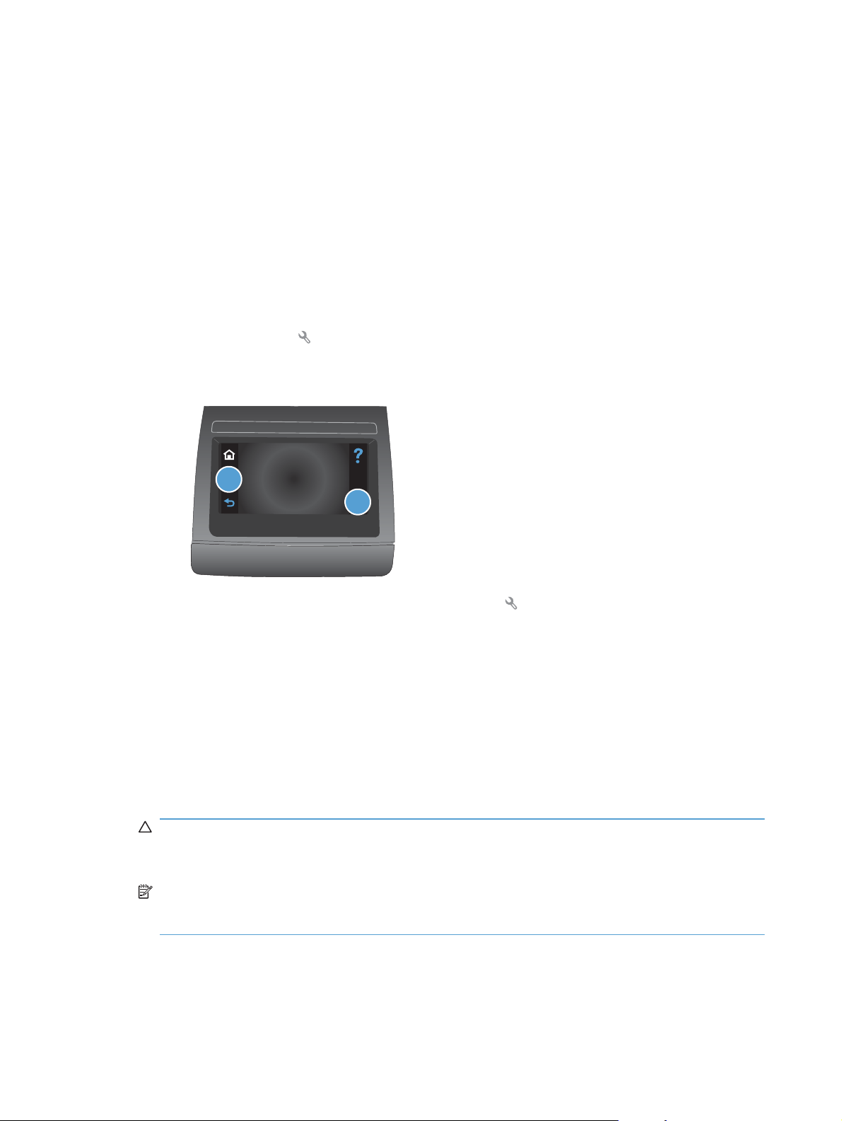
b. Touch the Setup
c. Touch the middle of the screen along the left-hand edge (callout 1), and then immediately
touch the lower-right corner (callout 2) of the screen.
button.
1
2
d. When the Home screen appears, touch the Setup button again.
e. Touch the 2ndary Service button.
f. Touch the arrow buttons (at the right- or left-side of the touch screen) until the Pick roller
button appears.
g. Touch the Pick roller button.
h. Touch the OK button to confirm that you want the pick roller to rotate.
i. Turn the product power off, and then remove the power cord and the interface cable.
2. Carefully place the product front-side up.
CAUTION: The document-feeder and scanner cover are not captive and can open suddenly if
the product is placed front-side up. Always support the document-feeder and scanner cover
before placing the product front-side up.
NOTE: Debris can scratch or damage the back of the product. Before you place the product
front-side up, remove any debris from the work surface. If possible, set the product on a clean,
dry cloth to prevent scratching and damage.
8 Chapter 1 Removal and replacement ENWW
Page 27
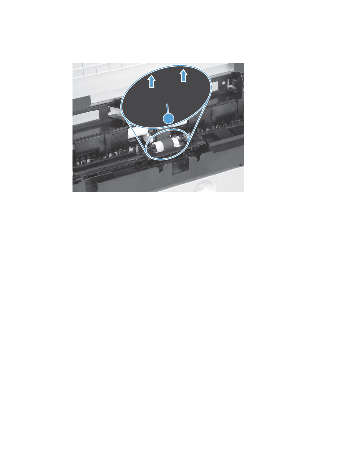
3. Release two white plastic locking tabs and remove the pickup roller.
CAUTION: Do not touch the spongy roller surface unless you are going to replace the roller.
Skin oils on the roller can cause paper pickup problems.
Figure 1-3 Remove the pickup roller
ENWW Removal and replacement procedures 9
Page 28
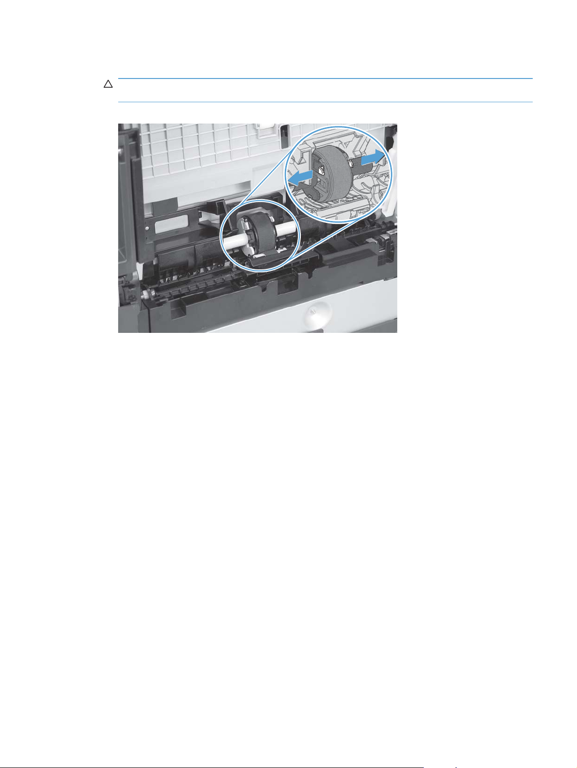
Separation roller
CAUTION: Do not touch the spongy roller surface unless you are going to replace the roller. Skin
oils on the roller can cause paper pickup problems.
1. Remove paper tray (if installed), and then carefully place the product front-side up.
CAUTION: The document-feeder and scanner cover are not captive and can open suddenly if
the product is placed front-side up. Always support the document-feeder and scanner cover
before placing the product front-side up.
NOTE: Debris can scratch or damage the back of the product. Before you place the product
front-side up, remove any debris from the work surface. If possible, set the product on a clean,
dry cloth to prevent scratching and damage.
2. Carefully release the roller cover and rotate it down and away from the roller.
Reinstallation tip Make sure that this cover snaps into place over the roller when the roller
and holder are reinstalled.
Figure 1-4 Remove the separation roller (1 of 2)
10 Chapter 1 Removal and replacement ENWW
Page 29
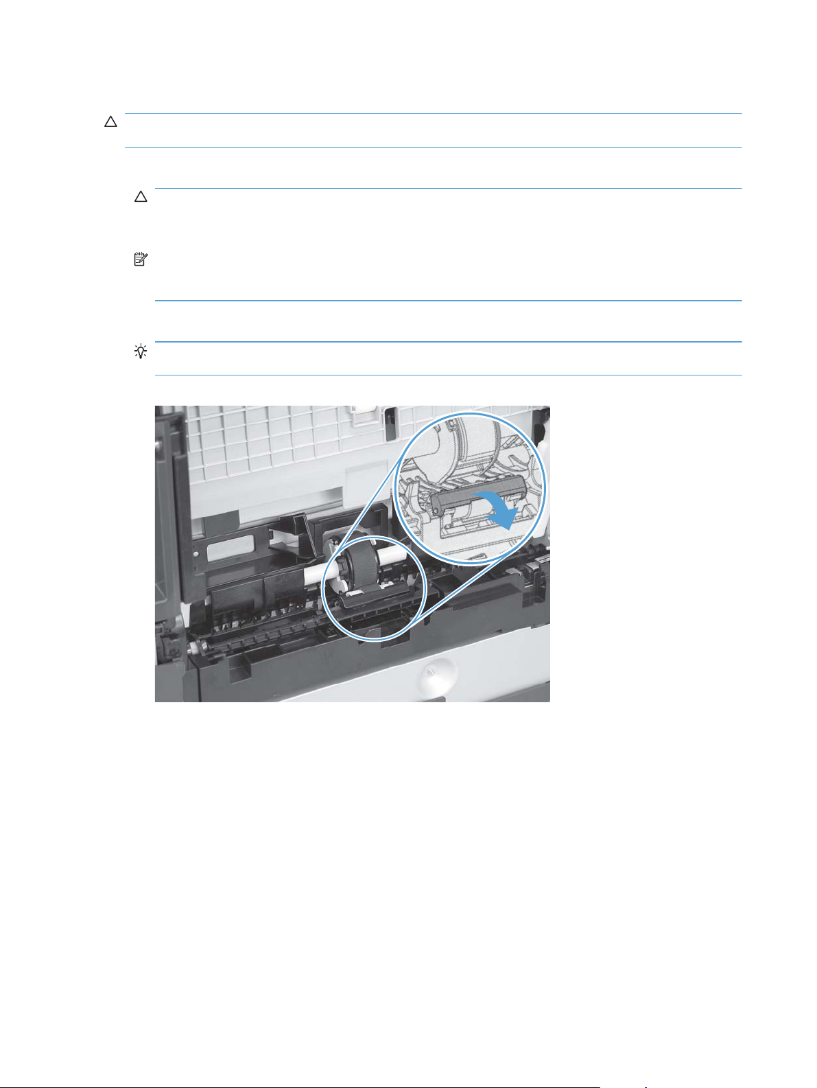
3. Use a small flat blade screwdriver to gently pry up on the roller and holder assembly (callout 1)
to remove the roller and holder assembly.
Figure 1-5 Remove the separation roller (2 of 2)
1
ENWW Removal and replacement procedures 11
Page 30

Transfer roller
1. Open the rear door.
2. Release the retainer clip and then rotate it until the pin on the clip aligns with the slot in the
mounting bracket.
Figure 1-6 Remove the transfer roller (1 of 3)
3. Remove the clip. Repeat these steps for the remaining retainer clip (located at the opposite end
of the roller shaft).
TIP: One of the clips (callout 1) is made from a black conductive plastic. Make sure that the
clips are reinstalled on correct the end of the transfer roller.
Figure 1-7 Remove the transfer roller (2 of 3)
1
12 Chapter 1 Removal and replacement ENWW
Page 31

4. Slide the roller to one side to disengage the roller shaft from the mounting bracket, and then
remove the transfer roller.
CAUTION: Do not touch the black sponge portion of the roller. Skin oils can cause print-quality
problems.
Figure 1-8 Remove the transfer roller (3 of 3)
ENWW Removal and replacement procedures 13
Page 32

Print-cartridge drawer
1. Open the front door and pull out the print-cartridge drawer.
Figure 1-9 Remove the print-cartridge drawer (1 of 5)
2. Use a small flat blade screwdriver to release one tab (callout 1) on the cartridge-drawer stop.
Figure 1-10 Remove the print-cartridge drawer (2 of 5)
1
14 Chapter 1 Removal and replacement ENWW
Page 33

3. Push in on the edge of the top cover (callout 1), rotate the end of the drawer stop toward the
center of the print-cartridge drawer (callout 2), and then remove the drawer stop (callout 3)
Figure 1-11 Remove the print-cartridge drawer (3 of 5)
1
2
3
4. Repeat the previous steps to remove the remaining drawer stop.
Figure 1-12 Remove the print-cartridge drawer (4 of 5)
ENWW Removal and replacement procedures 15
Page 34

5. Pull the print-cartridge drawer out of the product to remove it.
Figure 1-13 Remove the print-cartridge drawer (5 of 5)
16 Chapter 1 Removal and replacement ENWW
Page 35

Right cover
1. Before proceeding, note the locations of the retaining clips on the back of the cover.
Figure 1-14 Remove the right cover (1 of 5)
2. Remove one screw (callout 1).
Figure 1-15 Remove the right cover (2 of 5)
1
ENWW Removal and replacement procedures 17
Page 36

3. Release two tabs (callout 1), and then slightly separate the back side of the cover from the
product.
Figure 1-16 Remove the right cover (3 of 5)
1
4. Pull down on the bottom-front corner of the cover, and then slightly rotate the bottom of the
cover away from the product.
Figure 1-17 Remove the right cover (4 of 5)
18 Chapter 1 Removal and replacement ENWW
Page 37

5. Slide the cover toward the back of the product to remove it.
Figure 1-18 Remove the right cover (5 of 5)
ENWW Removal and replacement procedures 19
Page 38

Right-front cover-1 and cover-2
1. Remove the right cover. See Right cover on page 17.
2. Remove two screws (callout 1), and then remove the right-front cover-2 (callout 2)
Figure 1-19 Remove the right-front cover (1 of 4)
2
1
3. Open the front door, and then use a small flat blade screwdriver to release one tab (callout 1).
Figure 1-20 Remove the right-front cover (2 of 4)
1
20 Chapter 1 Removal and replacement ENWW
Page 39

4. Rotate the top of the right-front cover-1 away from the product, and then lift the cover up to
release it.
Figure 1-21 Remove the right-front cover (3 of 4)
5. Remove the right-front cover-1.
Figure 1-22 Remove the right-front cover (4 of 4)
ENWW Removal and replacement procedures 21
Page 40

Control panel
1. Remove the following components:
● Right cover. See
Right-front cover-1 and cover-2. See
●
2. Remove one locator screw (callout 1), and then remove the ESD bracket screw (callout 2) and
the mounting screw (callout 3).
NOTE: When the control panel is reinstalled, install the locator screw (callout 1) first to
correctly position the control panel on the product. Install the ESD bracket screw (callout 2) and
the mounting screw (callout 3) after the locator screw is tightened.
Figure 1-23 Remove the control panel (1 of 5)
Right cover on page 17.
Right-front cover-1 and cover-2 on page 20.
3
1
2
22 Chapter 1 Removal and replacement ENWW
Page 41

3. Slightly slide the control panel toward the front of the product, and then lift it off of the product.
CAUTION: The control panel is still attached to the product by the FFCs. Do not damage the
FFCs when you separate the control panel from the product.
Figure 1-24 Remove the control panel (2 of 5)
4. Disconnect two FFCs (callout 1) from the bottom of the control-panel PCA.
Figure 1-25 Remove the control panel (3 of 5)
1
ENWW Removal and replacement procedures 23
Page 42

5. Turn the control panel over, and then remove five screws (callout 1) and the ESD bracket
(callout 2).
NOTE: Install the ESD bracket on the replacement control-panel PCA assembly.
Figure 1-26 Remove the control panel (4 of 5)
1
2
6. Separate the control-panel base (callout 1) from the control-panel PCA assembly (callout 2).
Figure 1-27 Remove the control panel (5 of 5)
1
2
24 Chapter 1 Removal and replacement ENWW
Page 43

Left cover
1. Before proceeding, note of the locations of the retaining tabs on the back of the left cover.
2. Remove one screw (callout 1).
Figure 1-28 Remove the left cover (1 of 6)
Figure 1-29 Remove the left cover (2 of 6)
1
ENWW Removal and replacement procedures 25
Page 44

3. Release one tab (callout 1).
Figure 1-30 Remove the left cover (3 of 6)
1
4. Push in on the back side of the cover to release one tab (callout 1), and rotate the back edge of
the cover away from the product.
Figure 1-31 Remove the left cover (4 of 6)
1
26 Chapter 1 Removal and replacement ENWW
Page 45

5. Open the front door, and then use a small flat blade screwdriver to release two tabs (callout 1)
Figure 1-32 Remove the left cover (5 of 6)
1
6. Rotate the cover toward the front of the product, and then remove the cover.
Figure 1-33 Remove the left cover (6 of 6)
ENWW Removal and replacement procedures 27
Page 46

Document-feeder and scanner assembly
1. Remove the right cover. See Right cover on page 17.
2. Disconnect two FFCs (callout 1).
Figure 1-34 Remove the document-feeder and scanner assembly (1 of 3)
1
3. Remove four screws (callout 1).
Figure 1-35 Remove the document-feeder and scanner assembly (2 of 3)
1
28 Chapter 1 Removal and replacement ENWW
Page 47

4. Slightly slide the document-feeder and scanner assembly toward the rear of the product, and
then lift it straight up and off of the product.
Figure 1-36 Remove the document-feeder and scanner assembly (3 of 3)
ENWW Removal and replacement procedures 29
Page 48

Rear-center cover
1. Remove the right cover. See Right cover on page 17.
2. Open the rear door.
3. Use a small flat blade screwdriver to release one tab (callout 1), and then slightly separate the
top of the cover from the product.
Figure 1-37 Remove the rear-center cover (1 of 2)
1
4. Release one tab (callout 1), and then remove the rear-center cover (callout 2).
Figure 1-38 Remove the rear-center cover (2 of 2)
1
2
30 Chapter 1 Removal and replacement ENWW
Page 49

Rear-upper cover
1. Remove the following components:
● Right cover. See
Left cover. See
●
Rear-center cover. See
●
2. Remove four screws (callout 1).
Figure 1-39 Remove the rear-upper cover (1 of 4)
Right cover on page 17.
Left cover on page 25.
Rear-center cover on page 30.
1
3. Slightly separate the scanner assembly from the product base.
CAUTION: The scanner assembly is still connected to the product base by two FFCs.
Separate the assembly from the base only enough to remove the cover.
Figure 1-40 Remove the rear-upper cover (2 of 4)
ENWW Removal and replacement procedures 31
Page 50

4. Open the rear door. Use a small flat blade screwdriver to push down on two tabs (callout 1) to
release them.
Figure 1-41 Remove the rear-upper cover (3 of 4)
1
5. Rotate the bottom of the rear-upper cover away from the product to remove it.
Figure 1-42 Remove the rear-upper cover (4 of 4)
32 Chapter 1 Removal and replacement ENWW
Page 51

Speaker
1. Remove the following components:
● Right cover. See
Right-front cover-1 and cover-2. See
●
Control panel. See
●
2. Disconnect one wire-harness connector (callout 1), and then release the wire harness from the
retainers (callout 2).
Figure 1-43 Remove the speaker (1 of 2)
Right cover on page 17.
Right-front cover-1 and cover-2 on page 20.
Control panel on page 22.
1
2
3. Disconnect one wire-harness connector (callout 1), and then release the wire harness from the
retainers (callout 2).
Figure 1-44 Remove the speaker (2 of 2)
ENWW Removal and replacement procedures 33
Page 52

Top cover
1. Remove the following components:
● Right cover. See
Right-front cover-1 and cover-2. See
●
Control panel. See
●
Left cover. See
●
Document-feeder and scanner assembly. See
●
on page 28.
Rear-center cover. See
●
Rear-upper cover. See
●
Speaker on page 33.
●
2. Wireless models only: Disconnect one wire-harness connector (callout 1), remove one screw
(callout 2), and then remove the wireless PCA (callout 3).
Figure 1-45 Remove the top cover (1 of 3)
Right cover on page 17.
Right-front cover-1 and cover-2 on page 20.
Control panel on page 22.
Left cover on page 25.
Document-feeder and scanner assembly
Rear-center cover on page 30.
Rear-upper cover on page 31.
3
1
2
34 Chapter 1 Removal and replacement ENWW
Page 53

3. Remove seven screws (callout 1).
Figure 1-46 Remove the top cover (2 of 3)
4. Remove the top cover.
Figure 1-47 Remove the top cover (3 of 3)
1
ENWW Removal and replacement procedures 35
Page 54

Front door and front-lower cover
1. Remove the following components:
● Print-cartridge drawer. See
Left cover. See
●
2. Remove the paper tray (if installed), and then carefully place the product front-side up
CAUTION: The document-feeder and scanner cover are not captive and can open suddenly if
the product is placed front-side up. Always support the document-feeder and scanner cover
before placing the product front-side up.
3. Release three tabs (callout 1) and then push the guide into the product (away from the input-
tray cavity).
Figure 1-48 Remove the front door and front-lower cover (1 of 8)
Left cover on page 25.
Print-cartridge drawer on page 14.
1
36 Chapter 1 Removal and replacement ENWW
Page 55

4. Remove the guide.
Figure 1-49 Remove the front door and front-lower cover (2 of 8)
5. Carefully push the right-side front-lower door hinge in toward the center of the door to release it
from the hinge pin.
Figure 1-50 Remove the front door and front-lower cover (3 of 8)
ENWW Removal and replacement procedures 37
Page 56

6. Slide the door to the right to release the left-side hinge. Remove the front-lower door.
Figure 1-51 Remove the front door and front-lower cover (4 of 8)
7. Use a small flat blade screwdriver to release one retainer pin (callout 1) on the left-side front-
door cam. Remove the retainer pin.
Figure 1-52 Remove the front door and front-lower cover (5 of 8)
1
38 Chapter 1 Removal and replacement ENWW
Page 57

8. Repeat the previous step for the right-side retainer pin.
Reinstallation tip The door pins are keyed to the door cam. The pins must be correctly
positioned when they are reinstalled or they will not completely seat in the door cam.
Figure 1-53 Remove the front door and front-lower cover (6 of 8)
9. Release one tab (callout 1), rotate the door retainer clip up and away from the door, and then
remove the clip.
NOTE: Support the door when this clip is removed.
Figure 1-54 Remove the front door and front-lower cover (7 of 8)
1
ENWW Removal and replacement procedures 39
Page 58

10. Lower the left side of the door, and then slide it to the left to release the right-side door hinge pin.
Remove the door.
Figure 1-55 Remove the front door and front-lower cover (8 of 8)
40 Chapter 1 Removal and replacement ENWW
Page 59

Rear door and rear-lower cover
1. Remove the following components:
● Right cover. See
Left cover. See
●
Rear-center cover. See
●
2. Remove two screws (callout 1)
Figure 1-56 Remove the rear door and rear-lower cover (1 of 5)
Right cover on page 17.
Left cover on page 25.
Rear-center cover on page 30.
1
3. Release one pin (callout 1) and then slide the rear door and rear-lower cover towards the side of
the product with the interface connectors.
Figure 1-57 Remove the rear door and rear-lower cover (2 of 5)
1
ENWW Removal and replacement procedures 41
Page 60

4. Remove the rear door and rear-lower cover.
Figure 1-58 Remove the rear door and rear-lower cover (3 of 5)
5. Carefully pry the rear-door hinge arms off of the hinge pins (callout 1) on the rear-lower cover to
separate the rear cover from the rear door.
Figure 1-59 Remove the rear door and rear-lower cover (4 of 5)
1
42 Chapter 1 Removal and replacement ENWW
Page 61

6. Separate the rear cover from the rear door.
NOTE: If you are installing a replacement rear-lower door, remove the paper-guide assembly
from the discarded door, and then install it on the replacement door. See
Paper-guide assembly
on page 44.
Figure 1-60 Remove the rear door and rear-lower cover (5 of 5)
ENWW Removal and replacement procedures 43
Page 62

Main assemblies
NOTE: The laser scanner installed in this product is not replaceable.
Paper-guide assembly
1. Release one captive screw (callout 1) and release two tabs (callout 2).
Figure 1-61 Remove the paper-guide assembly (1 of 2)
1
2
2. Rotate the assembly up and away from the rear door to release it, and then remove the paper-
guide assembly
Figure 1-62 Remove the paper-guide assembly (2 of 2)
44 Chapter 1 Removal and replacement ENWW
Page 63

USB port PCA and bracket
NOTE: To replace only the USB port PCA, you do not need to remove the sheet-metal bracket.
Remove the two screws securing the PCA to the bracket, and then disconnect one wire-harness
connector.
Some parts are sensitive to electrostatic discharge (ESD). Always perform service work at an
ESD-protected workstation or mat. If an ESD workstation or mat is not available, ground yourself by
touching the sheet-metal chassis before touching an ESD-sensitive part.
1. Remove the following components:
Right cover. See
●
Right-front cover-1 and cover-2. See
●
2. Remove two screws (callout 1), and then remove the USB port and sheet-metal mounting
bracket.
CAUTION: The USB port PCA is still connected to the product by the wire harness.
Figure 1-63 Remove the USB port PCA and bracket (1 of 3)
Right cover on page 17.
Right-front cover-1 and cover-2 on page 20.
1
ENWW Removal and replacement procedures 45
Page 64

3. Disconnect one wire-harness connector (callout 1).
Figure 1-64 Remove the USB port PCA and bracket (2 of 3)
1
4. Remove two screws (callout 1), and then separate the USB port PCA (callout 2) from the
mounting bracket (callout 3) to remove it.
Figure 1-65 Remove the USB port PCA and bracket (3 of 3)
2
1
3
46 Chapter 1 Removal and replacement ENWW
Page 65

Reinstall the USB port PCA
● When the USB port PCA and mounting bracket are reinstalled, make sure that the cable is
routed behind the cable retainers (callout 1)
Figure 1-66 Reinstall the USB port PCA and bracket
1
ENWW Removal and replacement procedures 47
Page 66

Wireless PCA (wireless models only)
CAUTION: Some parts are sensitive to electrostatic discharge (ESD). Always perform service
work at an ESD-protected workstation or mat. If an ESD workstation or mat is not available, ground
yourself by touching the sheet-metal chassis before touching an ESD-sensitive part.
1. Remove the right cover. See Right cover on page 17.
2. Disconnect one wire-harness connector, and then remove one screw (callout 2).
Figure 1-67 Remove the wireless PCA (1 of 2)
2
1
3. Remove the wireless PCA.
Figure 1-68 Remove the wireless PCA (2 of 2)
48 Chapter 1 Removal and replacement ENWW
Page 67

DC controller PCA
Special considerations
WARNING! Do not install a replacement formatter PCA and DC controller PCA at the same time.
The formatter PCA and the DC controller PCA store important product configuration information
(NVRAM data) that will be lost if both PCAs are replaced at the same time. When the product power
is turned on, the formatter will restore the NVRAM data to a replacement DC controller.
Replacing both the DC controller and the formatter at the same time will result in severe print-quality
problems.
Replacing the DC controller PCA before the formatter PCA
Use the following procedure if you need to install a replacement DC controller and a replacement
formatter PCA.
NOTE: If you are only installing a replacement DC controller PCA, proceed to Remove the DC
controller PCA on page 49.
1. Install a replacement DC controller PCA.
2. Turn the product power on, and wait for the print-cartridge volume indicators to appear on the
control-panel display.
NOTE: This allows important product information to be written to the replacement DC controller
PCA.
3. Turn the product power off.
4. Install a replacement formatter PCA. See
on page 53.
5. Turn the product power on.
Remove the DC controller PCA
CAUTION: Do not bend or fold the flat flexible cables (FFCs) during removal or installation. Also, do
not straighten pre-folds in the FFCs. You must make sure that all FFCs are fully seated in their
connectors. Failure to fully seat an FFC into a connector can cause a short circuit in a PCA.
Some parts are sensitive to electrostatic discharge (ESD). Always perform service work at an
ESD-protected workstation or mat. If an ESD workstation or mat is not available, ground yourself by
touching the sheet-metal chassis before touching an ESD-sensitive part.
1. Remove the right cover. See Right cover on page 17.
Formatter PCA, fax card PCA, and support bracket
ENWW Removal and replacement procedures 49
Page 68

2. Release one tab (callout 1) on the black-plastic protective cover.
NOTE: This cover is located near the lower-right side of the product below the DC controller.
Figure 1-69 Remove the DC controller PCA (1 of 5)
1
3. Remove the cover.
Figure 1-70 Remove the DC controller PCA (2 of 5)
50 Chapter 1 Removal and replacement ENWW
Page 69

4. Disconnect fifteen wire-harness connectors and three FFCs from the DC controller PCA.
Figure 1-71 Remove the DC controller PCA (3 of 5)
16
7
18
65
12
17
4
11
13
15
9
10
3
8
2
Item Description Item Description Item Description
1 J102
Low-voltage power
supply (+24 v)
2 J103
1
7 J109
8 J110
14
Scanner motor
13 J116
Pickup assembly sensors
14 J118
Low-voltage power
supply (+3.3 v)
3 J104
Fuser thermistor
4 J105
Fuser power
5 J107
Formatter
6 J108
Laser
Fuser motor
9 J111
Pickup assembly motor
10 J112
Developing disengagement
solenoid
11 J113
Pickup solenoid
12 J115
High-voltage power supply
Media width sensor
15 J119
ITB assembly sensors
16 J120
Developing home position
sensor
17 J121
Main motor
18 J124
E-label
ENWW Removal and replacement procedures 51
Page 70

5. Remove four screws (callout 1).
NOTE: These four screws are ground screws. Make sure that the correct screws are used to
reinstall the DC controller PCA.
Figure 1-72 Remove the DC controller PCA (4 of 5)
1
6. Remove the DC controller PCA.
Figure 1-73 Remove the DC controller PCA (5 of 5)
52 Chapter 1 Removal and replacement ENWW
Page 71

Formatter PCA, fax card PCA, and support bracket
Special considerations
WARNING! Do not install a replacement formatter PCA and DC controller PCA at the same time.
The formatter PCA and the DC controller PCA store important product configuration information
(NVRAM data) that will be lost if both PCAs are replaced at the same time. When the product power
is turned on, the DC controller will restore the NVRAM data on the replacement formatter.
Replacing both the formatter and the DC controller at the same time will result in severe print-quality
problems.
NOTE: The base model does not have a fax card installed.
Replacing the formatter PCA before the DC controller PCA
Use the following procedure if you need to install a replacement formatter PCA and a replacement
DC controller.
NOTE: If you are only installing a replacement formatter PCA, proceed to Remove the formatter
PCA on page 53.
1. Install a replacement formatter PCA.
2. Turn the product power on, and wait for the print-cartridge volume indicators to appear on the
control-panel display.
NOTE: This allows important product information to be written to the replacement formatter
PCA.
3. Turn the product power off.
4. Install a replacement DC controller. See
5. Turn the product power on.
Remove the formatter PCA
CAUTION: Do not bend or fold the flat flexible cables (FFCs) during removal or installation. Also, do
not straighten pre-folds in the FFCs. You must make sure that all FFCs are fully seated in their
connectors. Failure to fully seat an FFC into a connector can cause a short circuit in a PCA.
Some parts are sensitive to electrostatic discharge (ESD). Always perform service work at an
ESD-protected workstation or mat. If an ESD workstation or mat is not available, ground yourself by
touching the sheet-metal chassis before touching an ESD-sensitive part.
1. Remove the right cover. See Right cover on page 17.
DC controller PCA on page 49.
ENWW Removal and replacement procedures 53
Page 72

2. Disconnect one connector (callout 1), and remove four screws (callout 2).
Figure 1-74 Remove the formatter PCA, fax card PCA, and support bracket (1 of 8)
2
1
3. Remove the Fax PCA.
Figure 1-75 Remove the formatter PCA, fax card PCA, and support bracket (2 of 8)
54 Chapter 1 Removal and replacement ENWW
Page 73

4. Disconnect six wire-harness connectors and four FFCs on the formatter PCA.
Figure 1-76 Remove the formatter PCA, fax card PCA, and support bracket (3 of 8)
5
6
2
4
9
8
10
7
3
Item Description Item Description
1
1J1
Wireless PCA (wireless models only)
2J8
Speaker
3J10
6J18
Document feeder motor (ADF)
7J19
USB PCA (thumb drive)
8J23
Power (LVPS)
4J13
Fax PCA
5J17
Scanner
Control panel
9J24
Control panel
10 J31
Video
ENWW Removal and replacement procedures 55
Page 74

5. Remove six screws (callout 1).
Figure 1-77 Remove the formatter PCA, fax card PCA, and support bracket (4 of 8)
1
6. Remove the formatter PCA.
Figure 1-78 Remove the formatter PCA, fax card PCA, and support bracket (5 of 8)
56 Chapter 1 Removal and replacement ENWW
Page 75

7. Remove one FFC (callout 1) from the support bracket. Disconnect one FFC (callout 2) from the
DC controller.
CAUTION: One FFC (callout 2) is fastened to the support bracket with insulating adhesive
foam tape. If you are replacing the support bracket, you will need to adhere this FFC to the
replacement bracket with the same type of material. This FFC must be shielded from direct
contact with the support bracket.
Figure 1-79 Remove the formatter PCA, fax card PCA, and support bracket (6 of 8)
1
2
8. Remove six screws (callout 1).
Figure 1-80 Remove the formatter PCA, fax card PCA, and support bracket (7 of 8)
1
ENWW Removal and replacement procedures 57
Page 76

9. Remove the support bracket.
Figure 1-81 Remove the formatter PCA, fax card PCA, and support bracket (8 of 8)
58 Chapter 1 Removal and replacement ENWW
Page 77

Fuser motor
1. Remove the following components:
Right cover. See
●
Formatter PCA, fax PCA, and support bracket. See
●
support bracket on page 53.
2. Disconnect one wire-harness connector (callout 1), and then remove two screws (callout 2).
Figure 1-82 Remove the fuser motor (1 of 2)
Right cover on page 17.
Formatter PCA, fax card PCA, and
2
1
3. Slightly slide the motor up so that the gear on the motor shaft is centered in the mounting
bracket hole, and then pull the motor away from the product. The gear will pass through the
large hole in the bracket.
Figure 1-83 Remove the fuser motor (2 of 2)
ENWW Removal and replacement procedures 59
Page 78

Main motor
1. Remove the following components:
Right cover. See
●
Formatter PCA, fax PCA, and support bracket. See
●
support bracket on page 53.
2. Disconnect one wire-harness connector (callout 1), and then release the wire harness from the
retainer (callout 2).
Figure 1-84 Remove the main motor (1 of 4)
Right cover on page 17.
Formatter PCA, fax card PCA, and
2
1
3. Release two tabs (callout 1), and then pull down on the black-plastic wire-harness retainer to
release it.
Figure 1-85 Remove the main motor (2 of 4)
1
60 Chapter 1 Removal and replacement ENWW
Page 79

4. Remove the wire retainer.
Figure 1-86 Remove the main motor (3 of 4)
5. Remove four screws (callout 1) and then remove the main motor.
Figure 1-87 Remove the main motor (4 of 4)
1
ENWW Removal and replacement procedures 61
Page 80

Intermediate transfer belt (ITB)
1. Remove the following components:
Print-cartridge drawer. See
●
Right cover. See
●
Left cover. See
●
Rear-center cover. See
●
2. Disconnect one wire-harness connector (callout 1), and then release the wire harness from the
retainer (callout 2).
Figure 1-88 Remove the ITB (1 of 5)
Right cover on page 17.
Left cover on page 25.
Print-cartridge drawer on page 14.
Rear-center cover on page 30.
1
2
62 Chapter 1 Removal and replacement ENWW
Page 81

3. Open the rear door, and then remove one screw (callout 1), and then remove the print-cartridge
drawer stop (callout 2).
Figure 1-89 Remove the ITB (2 of 5)
2
1
4. Carefully lift up on the black plastic portion of the ITB, and then pull it partially out of the product
(the ITB wire harness will prevent the ITB from being fully removed).
WARNING! Only partially pull the ITB out of the product to avoid damage to the secondary-
transfer (T2) roller.
Figure 1-92 Remove the ITB (5 of 5) on page 64 to see how to correctly handle the ITB to
See
prevent damaging it. Do not lift the ITB by grasping the sheet-metal bracket.
CAUTION: Avoid touching the black plastic transfer belt. Skin oils on the belt might cause
print-quality problems.
Figure 1-90 Remove the ITB (3 of 5)
ENWW Removal and replacement procedures 63
Page 82

5. Feed the ITB wire harness (callout 1) through an opening in the chassis (callout 2).
Figure 1-91 Remove the ITB (4 of 5)
2
1
6. Carefully pull the ITB straight out of the product.
WARNING! Handle the ITB by its hard plastic sides to avoid damage to the sheet metal frame.
The lower sheet-metal portion of the ITB frame can be easily bent. See callout 1 in
Reinstall the ITB (1 of 2) on page 65.
Figure 1-93
CAUTION: Make sure that the ITB wire harness does not get damaged as the ITB is removed
from the chassis.
Figure 1-92 Remove the ITB (5 of 5)
64 Chapter 1 Removal and replacement ENWW
Page 83

Reinstall the ITB
Use the following guidelines when you install the ITB.
●
WARNING! The lower sheet-metal portion of the ITB frame (callout 1) can be easily bent.
Avoid handling the ITB by this part of the sheet-metal frame.
Figure 1-93 Reinstall the ITB (1 of 2)
1
● When handling the ITB, always use the hard plastic portions of the assembly.
CAUTION: Avoid touching the black-plastic transfer belt or roller. Skin oils on the belt or roller
might cause print-quality problems.
Do not let the transfer belt contact hard or sharp objects.
●
CAUTION: Scratches, punctures, or other damage to the belt will cause print-quality problems.
Make sure that the wire harness is not twisted or pinched after it is passed through the opening
●
in the chassis, and that the ITB sits flat in the product.
NOTE: When the print-cartridge drawer is installed, it should easily slide in and out of the
product and not contact any part of the ITB assembly.
ENWW Removal and replacement procedures 65
Page 84

Tape the wire harness to the sheet-metal frame so that it will not catch on internal components
●
as the ITB is installed.
With the ITB partially installed, feed the wire harness through the opening in the chassis. See
Figure 1-91 Remove the ITB (4 of 5) on page 64. Finish installing the ITB.
WARNING! Do not place the tape so that it makes contact or adheres to the transfer belt. Tape
or tape residue on the transfer belt will cause print-quality problems.
Make sure that the ITB is fully seated in the product before you reinstall the print-cartridge door
stop.
NOTE: Make sure that you remove all of the tape and tape residue after installing the ITB.
Figure 1-94 Reinstall the ITB (2 of 2)
66 Chapter 1 Removal and replacement ENWW
Page 85

Power supply (high-voltage)
CAUTION: Do not bend or fold the flat flexible cables (FFCs) during removal or installation. Also, do
not straighten pre-folds in the FFCs. You must make sure that all FFCs are fully seated in their
connectors. Failure to fully seat an FFC into a connector can cause a short circuit in a PCA.
Some parts are sensitive to electrostatic discharge (ESD). Always perform service work at an
ESD-protected workstation or mat. If an ESD workstation or mat is not available, ground yourself by
touching the sheet-metal chassis before touching an ESD-sensitive part.
1. Remove the following components:
Right cover. See
●
Right-front cover-1 and cover-2. See
●
Control panel. See
●
Left cover. See
●
Document-feeder and scanner assembly. See
●
on page 28.
Rear-center cover. See
●
Rear-upper cover. See
●
Speaker. See
●
Top cover. See
●
2. Disconnect one FFC (callout 1).
NOTE: This FFC connects the DC controller (shown below) to the high-voltage power supply.
Figure 1-95 Remove the power supply (high-voltage; 1 of 6)
Right cover on page 17.
Right-front cover-1 and cover-2 on page 20.
Control panel on page 22.
Left cover on page 25.
Document-feeder and scanner assembly
Rear-center cover on page 30.
Rear-upper cover on page 31.
Speaker on page 33
Top cover on page 34.
1
ENWW Removal and replacement procedures 67
Page 86

3. Disconnect two wire-harness connectors (callout 1) and release the wire harness from the
retainer (callout 2).
Figure 1-96 Remove the power supply (high-voltage; 2 of 6)
1
2
4. Remove one screw (callout 1) and then release the sub-PCA from the chassis (callout 2).
Figure 1-97 Remove the power supply (high-voltage; 3 of 6)
1
2
68 Chapter 1 Removal and replacement ENWW
Page 87

5. Remove four screws (callout 6).
Figure 1-98 Remove the power supply (high-voltage; 4 of 6)
1
6. Release seven tabs (callout 8).
Figure 1-99 Remove the power supply (high-voltage; 5 of 6)
1
ENWW Removal and replacement procedures 69
Page 88

7. Remove the power supply.
Figure 1-100 Remove the power supply (high-voltage; 6 of 6)
Reinstall the power supply (high voltage)
Make sure that the power supply is correctly positioned under the tabs (callout 1) located on the
●
product chassis. If the power supply is not correctly installed, the product will not function
correctly and a fuser open error (50.7000) might appear in the event log.
Figure 1-101 Reinstall the power supply (high voltage)
1
70 Chapter 1 Removal and replacement ENWW
Page 89

Power supply (low voltage)
CAUTION: Do not bend or fold the flat flexible cables (FFCs) during removal or installation. Also, do
not straighten pre-folds in the FFCs. You must make sure that all FFCs are fully seated in their
connectors. Failure to fully seat an FFC into a connector can cause a short circuit in a PCA.
Some parts are sensitive to electrostatic discharge (ESD). Always perform service work at an
ESD-protected workstation or mat. If an ESD workstation or mat is not available, ground yourself by
touching the sheet-metal chassis before touching an ESD-sensitive part.
1. Remove the following components:
Right cover. See
●
Left cover. See
●
Rear-center cover. See
●
Rear door and rear-lower cover. See
●
Formatter PCA, fax PCA, and support bracket. See
●
support bracket on page 53.
2. Remove two screws (callout 1) and the black-plastic cover (callout 2).
Figure 1-102 Remove the power supply (low voltage; 1 of 8)
Right cover on page 17.
Left cover on page 25.
Rear-center cover on page 30.
Rear door and rear-lower cover on page 41.
Formatter PCA, fax card PCA, and
1
2
ENWW Removal and replacement procedures 71
Page 90

3. Disconnect one wire-harness connector (callout 1) and release the wire harness from the
retainer (callout 2).
Figure 1-103 Remove the power supply (low voltage; 2 of 8)
1
2
4. Release one tab (callout 1) on the black-plastic protective cover.
NOTE: This cover is located near the lower-right side of the product below the DC controller.
Figure 1-104 Remove the power supply (low voltage; 3 of 8)
1
72 Chapter 1 Removal and replacement ENWW
Page 91

5. Remove the cover.
Figure 1-105 Remove the power supply (low voltage; 4 of 8)
6. Disconnect two wire-harness connectors (callout 1), and then release the wire harnesses from
the retainer (callout 2).
Figure 1-106 Remove the power supply (low voltage; 5 of 8)
1
2
ENWW Removal and replacement procedures 73
Page 92

7. Release two tabs (callout 1), and then pull the black-plastic cover away from the product to
remove it.
Figure 1-107 Remove the power supply (low voltage; 6 of 8)
1
8. Remove two screws (callout 1).
Figure 1-108 Remove the power supply (low voltage; 7 of 8)
1
74 Chapter 1 Removal and replacement ENWW
Page 93

9. Rotate the end of the power supply near the front of the product out and away from the product
(callout 1) until it clears the chassis, and then slide the power supply toward the front of the
product to remove it (callout 2).
NOTE: As you remove the power supply, feed the wire harness at the rear of the product
through the opening in the chassis (callout 3).
Figure 1-109 Remove the power supply (low voltage; 8 of 8)
3
1
2
Reinstall the power supply (low voltage)
1. Make sure that the hook on the power supply tray is correctly engaged with the slot at the back
side of the product chassis.
Figure 1-110 Reinstall the power supply (low voltage; 1 of 2)
ENWW Removal and replacement procedures 75
Page 94

2. Make sure that the power supply tray is correctly engaged with the mounting rail near the front of
the product chassis.
Figure 1-111 Reinstall the power supply (low voltage; 2 of 2)
76 Chapter 1 Removal and replacement ENWW
Page 95

Power supply (fuser)
CAUTION: Some parts are sensitive to electrostatic discharge (ESD). Always perform service
work at an ESD-protected workstation or mat. If an ESD workstation or mat is not available, ground
yourself by touching the sheet-metal chassis before touching an ESD-sensitive part.
1. Remove the following components:
Right cover. See
●
Left cover. See
●
Rear-center cover. See
●
Rear door and rear-lower cover. See
●
2. Remove two screws (callout 1) and the black-plastic cover (callout 2).
Figure 1-112 Remove the power supply (fuser; 1 of 5)
Right cover on page 17.
Left cover on page 25.
Rear-center cover on page 30.
Rear door and rear-lower cover on page 41.
1
2
ENWW Removal and replacement procedures 77
Page 96

3. Disconnect three wire-harness connectors (callout 1), and then remove the wire harness from
the retainer (callout 2).
Figure 1-113 Remove the power supply (fuser; 2 of 5)
1
2
4. Release one tab (callout 1), slide the retainer toward the formatter side of the product to release
it, and then remove the retainer from the chassis.
Figure 1-114 Remove the power supply (fuser; 3 of 5)
1
78 Chapter 1 Removal and replacement ENWW
Page 97

5. Remove four screws (callout 1).
NOTE: The two screws near the power switch are ground screws. Make sure that these
screws are placed in the correct positions when the power supply is reinstalled.
Figure 1-115 Remove the power supply (fuser; 4 of 5)
1
6. Remove the power supply.
Figure 1-116 Remove the power supply (fuser; 5 of 5)
ENWW Removal and replacement procedures 79
Page 98

Fuser
1. Remove the following components:
Right cover. See
●
Right-front cover-1 and cover-2. See
●
Control panel. See
●
Left cover. See
●
Document-feeder and scanner assembly. See
●
on page 28.
Rear-center cover. See
●
Rear-upper cover. See
●
Speaker. See
●
Top cover. See
●
Rear door and rear-lower cover. See
●
2. Remove two screws (callout 1) and the black plastic cover (callout 2).
Figure 1-117 Remove the fuser (1 of 4)
Right cover on page 17.
Right-front cover-1 and cover-2 on page 20.
Control panel on page 22.
Left cover on page 25.
Document-feeder and scanner assembly
Rear-center cover on page 30.
Rear-upper cover on page 31.
Speaker on page 33.
Top cover on page 34.
Rear door and rear-lower cover on page 41.
2
1
80 Chapter 1 Removal and replacement ENWW
Page 99

3. Disconnect five wire-harness connectors (callout 1). Remove the wire harness from the guides
(callout 2 and callout 3) and one retainer (callout 4).
Figure 1-118 Remove the fuser (2 of 4)
2
3
1
4
4. Remove four screws (callout 1).
Figure 1-119 Remove the fuser (3 of 4)
1
ENWW Removal and replacement procedures 81
Page 100

5. Remove the fuser.
CAUTION: Handle the fuser carefully. The sensors that are mounted to the output side of the
fuser can be easily dislodged. When the fuser is reinstalled, make sure that the sensors are
present, and correctly fastened to the fuser assembly.
Figure 1-120 Remove the fuser (4 of 4)
82 Chapter 1 Removal and replacement ENWW
 Loading...