

Page 1
HP Color LaserJet CM1015/CM1017 MFP
Service Manual
Page 2

Page 3

HP Color LaserJet CM1015/CM1017 MFP
Service Manual
Page 4

Copyright and License
Trademark Credits
© 2006 Copyright Hewlett-Packard
Development Company, L.P.
Reproduction, adaptation, or translation
without prior written permission is
prohibited, except as allowed under the
copyright laws.
The information contained in this document
is subject to change without notice.
The only warranties for HP products and
services are set forth in the express
warranty statements accompanying such
products and services. Nothing herein
should be construed as constituting an
additional warranty. HP shall not be liable
for technical or editorial errors or omissions
contained herein.
Part number CB394-90930
Edition 1, 10/2006
PostScript® is a trademark of Adobe
Systems Incorporated.
Microsoft® and Windows® are U.S.
registered trademarks of Microsoft
Corporation.
Pentium® is a registered trademark of Intel
corporation or its subsidiaries in the United
States and other countries.
ENERGY STAR® and the ENERGY STAR
logo® are U.S. registered marks of the
United States Environmental Protection
Agency. Details on the proper use of the
marks are explained in the "Guidelines for
Proper use of the ENERGY STAR® Name
and International Logo."
Page 5

Table of contents
1 Product information
HP Color LaserJet CM1015/1017 MFP configurations ......................................................................... 2
HP Color LaserJet CM1015/1017 MFP features ................................................................................... 3
Walkaround ............................................................................................................................................ 5
Software ................................................................................................................................................. 8
Software and supported operating systems ......................................................................... 8
Media specifications .............................................................................................................................. 9
Media supported on this MFP ............................................................................................... 9
Select print media ............................................................................................................... 10
Media that can damage the printer .................................................................... 11
Media to avoid .................................................................................................... 11
2 Installation
Site preparation ................................................................................................................................... 14
Operating environment ....................................................................................................... 14
Minimum system requirements ........................................................................................... 15
Requirements for PC systems ........................................................................... 15
Requirements for Macintosh systems ................................................................ 15
Package contents ................................................................................................................................ 16
Installing optional tray 3 ....................................................................................................................... 17
Installing memory DIMMs .................................................................................................................... 18
3 Managing and maintenance
Managing supplies ............................................................................................................................... 24
Life expectancies of supplies .............................................................................................. 24
Check and order supplies ................................................................................................... 24
Check supply status and order using the control panel ..................................... 24
Check and order supplies using HP ToolboxFX ................................................ 24
Check and order supplies using HP Solution Center ........................................ 24
Storing supplies .................................................................................................................. 25
Replacing and recycling supplies ....................................................................................... 25
HP policy on non-HP supplies ............................................................................................ 25
Reset the MFP for non-HP supplies .................................................................. 25
HP anti-counterfeit supplies Web site ................................................................................. 26
Cleaning the MFP ................................................................................................................................ 27
Clean the paper path using HP ToolboxFX ........................................................................ 27
Clean the scanner glass ..................................................................................................... 27
Calibrating the MFP ............................................................................................................................. 29
Calibrate the MFP from the front control panel. ................................................................. 29
ENWW iii
Page 6

Calibrate the MFP from HP ToolboxFX .............................................................................. 29
Management tools ............................................................................................................................... 30
Special pages ..................................................................................................................... 30
Demo page ......................................................................................................... 30
Configuration page ............................................................................................. 30
Supplies Status page ......................................................................................... 31
Networking page (CM1017 only) ....................................................................... 32
Fonts pages ........................................................................................................ 33
Usage page ........................................................................................................ 34
Service page ...................................................................................................... 34
Menu map ........................................................................................................................... 34
HP ToolboxFX ..................................................................................................................... 35
Open HP ToolboxFX .......................................................................................... 35
Status ................................................................................................................. 36
Event log ............................................................................................ 36
Alerts .................................................................................................................. 37
Set up status alerts ............................................................................ 37
Set up e-mail alerts ........................................................................... 37
Help .................................................................................................................... 37
System settings .................................................................................................. 38
Device information ............................................................................. 38
Paper handling .................................................................................. 39
Print quality ........................................................................................ 39
Print density ....................................................................................... 39
Paper types ....................................................................................... 40
System setup ..................................................................................... 40
Service ............................................................................................... 40
Device Polling Page .......................................................................... 40
Print Settings ...................................................................................................... 40
Printing .............................................................................................. 41
PCL5c ................................................................................................ 41
PostScript .......................................................................................... 41
Memory card (HP Color LaserJet CM1017 MFP only) ..................... 41
Network settings ................................................................................................. 41
Other links found in HP ToolboxFX .................................................................... 42
Embedded Web server ....................................................................................................... 42
Open the embedded Web server ....................................................................... 43
Status tab ........................................................................................................... 43
System tab ......................................................................................................... 43
Print tab .............................................................................................................. 44
Networking tab ................................................................................................... 44
4 Operational theory
Engine control system ......................................................................................................................... 46
Basic sequence of operation .............................................................................................. 46
Power-on sequence ............................................................................................................ 47
Motors and fans .................................................................................................................. 47
Main-motor failure detection (59.x errors) .......................................................... 48
Fan motor failure detection ................................................................................ 48
Image formation system ...................................................................................................................... 49
iv ENWW
Page 7

Pickup and feed system ...................................................................................................................... 50
Manual feed slot pickup mechanism .................................................................................. 51
Paper feed mechanism ....................................................................................................... 52
Skew correction by the registration shutter ........................................................................ 52
Jam detection ...................................................................................................................... 53
Printed circuit assembly locations ....................................................................................... 53
250-sheet tray solenoid and printed circuit locations ......................................................... 54
Scanner system ................................................................................................................................... 56
Scanner power-on sequence of events .............................................................................. 56
Copy or scan-to-computer sequence of events .................................................................. 57
Service-only tools ................................................................................................................................ 58
General timing chart ............................................................................................................ 58
Printer calibration ................................................................................................................ 59
5 Removal and replacement
Overview .............................................................................................................................................. 62
Service approach ................................................................................................................................. 63
Pre-service procedures ....................................................................................................... 63
Post-repair tests .................................................................................................................. 63
Removal and replacement procedures ............................................................................................... 65
Print cartridge replacement ................................................................................................. 66
ETB removal and replacement ........................................................................................... 69
Scanner removal and replacement ..................................................................................... 78
Face-up mechanism removal and replacement ................................................................. 80
Upper-cover assembly removal and replacement .............................................................. 82
Side cover removal and replacement ................................................................................. 82
Fuser removal and replacement ......................................................................................... 84
Formatter removal and replacement .................................................................................. 90
DC controller removal and replacement ............................................................................. 92
Separation assembly removal and replacement ................................................................ 95
Paper-pickup roller removal and replacement .................................................................... 96
Control panel removal and replacement ............................................................................. 99
Memory-card assembly removal and replacement (HP Color LaserJet CM1017 MFP
only) .................................................................................................................................. 100
Memory-card-reader cover removal and replacement ..................................................... 102
Scanner lid removal and replacement .............................................................................. 103
6 Troubleshooting
Unpack/power-on checklist ................................................................................................................ 106
Control-panel messages .................................................................................................................... 108
Clearing jams ..................................................................................................................................... 118
Where to look for jams ...................................................................................................... 118
Clear jams from inside the MFP ....................................................................................... 119
Clear jams from tray output area ...................................................................................... 121
Clear jams from the back of the MFP ............................................................................... 122
Clear jams from tray 2 or optional tray 3 .......................................................................... 123
E-Label-reader guide pin damage ..................................................................................................... 125
Print problems .................................................................................................................................... 126
Print-quality problems ....................................................................................................... 126
Identifying and correcting print defects ............................................................ 126
ENWW v
Page 8

Print-quality checklist ....................................................................... 126
General print-quality issues ............................................................. 127
Solve issues with printing color documents .................................... 131
Media-handling problems ................................................................................................. 132
Print-media guidelines ...................................................................................... 132
Solve print-media problems ............................................................................. 133
Performance problems ..................................................................................................... 134
Scan problems ................................................................................................................................... 136
Copy problems ................................................................................................................................... 139
Memory-card problems ...................................................................................................................... 143
Functional tests (SERVICE ONLY) ................................................................................................... 145
Engine-test print ................................................................................................................ 145
Service mode functions (SERVICE ONLY) ....................................................................................... 147
Cold reset .......................................................................................................................... 147
Restore defaults ................................................................................................................ 147
Cleaning mode .................................................................................................................. 147
USB speed ........................................................................................................................ 147
Less paper curl ................................................................................................................. 148
Archive print ...................................................................................................................... 148
NVRAM initialization ......................................................................................................... 148
Continuous self-test .......................................................................................................... 149
Scan calibration ................................................................................................................ 149
Display test ....................................................................................................................... 150
Control-panel button test .................................................................................................. 151
Show FW version .............................................................................................................. 151
Color calibration ................................................................................................................ 151
Memory cards ................................................................................................................... 152
Cleaning the ETB .............................................................................................................. 153
Troubleshooting tools ........................................................................................................................ 154
Device pages .................................................................................................................... 154
Demo page ....................................................................................................... 154
Configuration page ........................................................................................... 154
Supplies Status page ....................................................................................... 154
Error report ........................................................................................................................ 154
HP ToolboxFX ................................................................................................................... 154
View HP ToolboxFX ......................................................................................... 155
Troubleshooting tab ......................................................................................... 155
Repetitive-image-defect ruler ............................................................................................................ 156
Firmware and software updates ........................................................................................................ 157
7 Parts and diagrams
Overview ............................................................................................................................................ 160
Assembly locations ............................................................................................................................ 162
Upper Cover Assembly ...................................................................................................................... 170
Internal assemblies ............................................................................................................................ 172
Diagrams ........................................................................................................................................... 192
Alphabetical parts list ......................................................................................................................... 193
Numerical parts list ............................................................................................................................ 199
Appendix A Specifications
vi ENWW
Page 9

Multifunction peripheral (MFP) specifications ................................................................................... 206
Appendix B Service and support
Hewlett-Packard limited warranty statement ..................................................................................... 210
Print cartridge limited warranty statement ......................................................................................... 211
HP customer care .............................................................................................................................. 212
Availability of support and service ..................................................................................................... 213
HP Care Pack™ Services and Service Agreements ........................................................ 213
Appendix C Regulatory information
Introduction ........................................................................................................................................ 216
FCC regulations ................................................................................................................................. 217
Environmental Product Stewardship program ................................................................................... 218
Protecting the environment ............................................................................................... 218
Ozone production .............................................................................................................. 218
Power consumption .......................................................................................................... 218
HP LaserJet printing supplies ........................................................................................... 218
Disposal of waste equipment by users in private households in the European Union .... 220
Material safety data sheet ................................................................................................. 220
Declaration of conformity ................................................................................................................... 221
Country/region-specific safety statements ........................................................................................ 222
Laser safety statement ..................................................................................................... 222
Canadian DOC statement ................................................................................................. 222
Korean EMI statement ...................................................................................................... 222
VCCI statement (Japan) ................................................................................................... 222
Japanese Power Cord Statement ..................................................................................... 223
Finnish laser statement ..................................................................................................... 224
Index .................................................................................................................................................................. 225
ENWW vii
Page 10

viii ENWW
Page 11

1 Product information
HP Color LaserJet CM1015/1017 MFP configurations
●
HP Color LaserJet CM1015/1017 MFP features
●
Walkaround
●
Software
●
Media specifications
●
ENWW 1
Page 12
HP Color LaserJet CM1015/1017 MFP configurations
HP Color LaserJet CM1015 HP Color LaserJet CM1017
Speed. Prints 8 pages per minute (ppm) in color or
●
monochrome (black)
Trays. The MFPs include a single-sheet priority-feed
●
slot (tray 1) and a 250-sheet universal tray (tray 2)
Connectivity. Hi-Speed USB 2.0 port
●
Memory. 96MB of synchronous dynamic random-
●
access memory (SDRAM)
Display. Tilt screen two-line display
●
Optional 250-sheet tray 3
All the CM1015 MFP features plus the following:
●
Photo memory-card slots. CompactFlash, Memory
●
Stick / Memory Stick PRO, MultiMedia, Secure
Digital (SD), SmartMedia, and xD cards are
supported.
Display. Tilt screen graphical display
●
Connectivity. On-board networking
●
2 Chapter 1 Product information ENWW
Page 13

HP Color LaserJet CM1015/1017 MFP features
HP Color LaserJet CM1015/1017 MFP Series
Color printing
Excellent print quality
Ease of use
Flexible paper handling
Full color laser printing using the four process colors: cyan,
●
magenta, yellow, and black (CMYK).
HP print cartridges with ColorSphere toner achieve high
●
gloss for a range of bright colors.
ImageREt 2400 is a system of key color laser technologies
●
that offer excellent print quality.
True 600 by 600 dots per inch (dpi) text and graphics.
●
Adjustable settings to optimize print quality.
●
The few supplies are easy to install.
●
Convenient access to MFP information and settings using
●
the HP Solution Center and HP ToolboxFX software.
Convenient access to all supplies and to the paper path
●
through the front door.
HP Photosmart Premier
●
Adjust paper trays with one hand.
●
Trays 1 and 2 for letterhead, envelopes, labels,
●
transparencies, custom-sized media, postcards,
HP LaserJet glossy paper, HP LaserJet Tough paper,
heavy paper, and HP Laser Photo paper.
A 125-sheet top output bin.
●
Print on both sides (manually).
●
HP PCL6
Printer drivers
Interface connections
Energy savings
Economical printing
Archive printing When printing pages that are to be stored long-term, this option
●
HP postscript® level 3 emulation
●
Includes 35 built-in HP postscript level 3 language fonts.
Hi-Speed 2.0 USB port.
●
Built-in internal print server for connecting to a 10/100Base-
●
T network. (HP Color LaserJet CM1017 MFP only)
The MFP automatically conserves electricity by
●
substantially reducing power consumption when it is not
printing.
Meets ENERGY STAR® guidelines for energy efficiency.
●
N-up printing (printing more than one page on a sheet) and
●
Printing on Both Sides features save paper.
sets the printer to a mode that reduces toner smearing and
dusting.
The default setting is Off.
ENWW HP Color LaserJet CM1015/1017 MFP features 3
Page 14

HP Color LaserJet CM1015/1017 MFP Series
Supplies
Accessibility
Expandability
Memory card slots (HP Color LaserJet CM1017 MFP
only)
Copy
Scan
A Supplies Status page with print cartridge gauges that
●
estimate remaining supply level. Not available for non-HP
supplies.
No-shake cartridge design.
●
Authentication for original HP print cartridges.
●
Easy ordering for replacement supplies.
●
Online user guide compatible with text screen-readers.
●
All doors and covers can be opened by using one hand.
●
Optional tray 3. This 250-sheet universal tray prevents the
●
need to frequently add paper to the MFP. Only one
additional 250-sheet tray can be installed on the MFP.
One DIMM slot for adding memory.
●
Supports a variety of memory cards.
Provides full-color copying from letter/A4- sized scanner
●
glass.
Control panel buttons available for color and
●
monochromatic copying.
Provides 1200 pixels per inch (ppi), 24-bit full-color
●
scanning from letter/A4-sized scanner glass.
Scan-to Email
●
Scan-to Folder
●
4 Chapter 1 Product information ENWW
Page 15
Walkaround
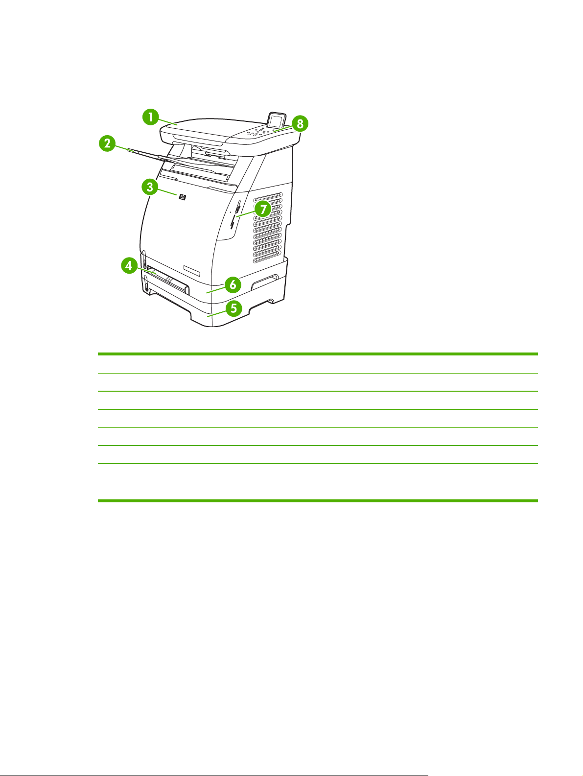
The following figures show the locations and names of key MFP components.
Figure 1-1 Front view (HP Color LaserJet CM1017 shown)
1 Scanner
2 Output bin
3 Front door
4 Tray 1 (single sheet priority feed slot)
5 Tray 3 (optional; 250 sheets)
6 Tray 2 (250 sheets)
7 Memory card slots (HP Color LaserJet CM1017 MFP)
8 MFP control panel
ENWW Walkaround 5
Page 16
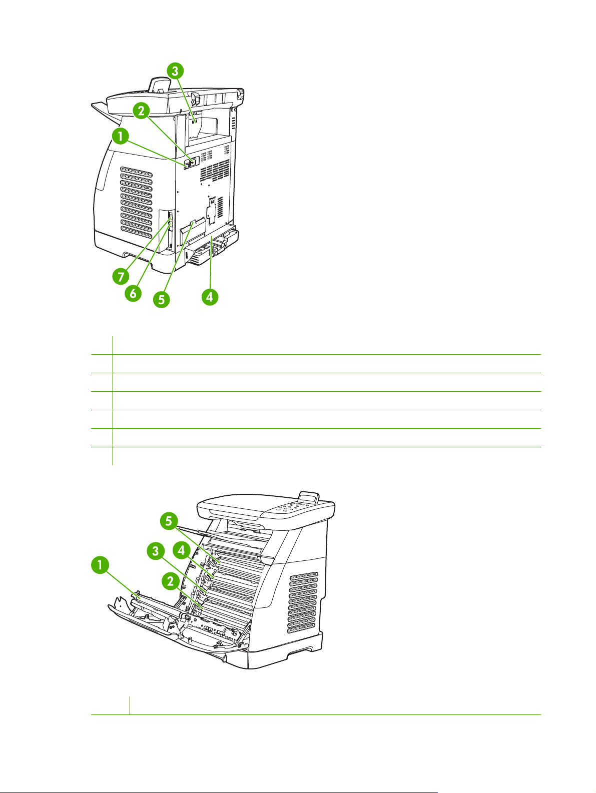
Figure 1-2 Back and side view
1 On/off switch
2 Power connection
3 Jam access door
4 Dust cover
5 DIMM access door
6 Network connection to 10/100 Base-T network (HP Color LaserJet CM1017 MFP only)
7 USB connection
Figure 1-3 Transfer belt view (HP Color LaserJet CM1015 MFP)
1 Transfer belt (ETB)
6 Chapter 1 Product information ENWW
Page 17

2 Magenta cartridge
3 Cyan cartridge
4 Yellow cartridge
5 Black cartridge
CAUTION Do not place anything on the transfer belt located on the inside of the front door.
Doing so can damage the MFP, adversely affecting print quality.
ENWW Walkaround 7
Page 18

Software
Software and supported operating systems
HP strongly recommends installing all of the software provided. Some software is not available in all
languages. See the Getting Started Guide for installation instructions, and see the Install Notes file
for the latest software information.
The most recent drivers, additional drivers, and other software are available from the Internet and
other sources.
The MFP supports the following operating systems:
●
●
●
Table 1-1 HP Color LaserJet CM1015/CM1017 MFP software
Microsoft® Windows® 2000 and Windows XP (32-bit and x64-bit support)
Macintosh OS X V10.3 and later
Microsoft Windows Server 2003 (32-bit and 64-bit, driver only)
NOTE Download the printer driver at http://www.hp.com/support/cljCM1015_1017.
Feature Microsoft Windows
Windows Installer
HP PCL6 printer driver
HP postscript level 3
emulation printer driver
HP ToolboxFX software
HP imaging software
(HP Color LaserJet CM1017
MFP only)
Macintosh Installer
Macintosh printer drivers
Scan driver
Mass Storage Driver
(HP Color LaserJet CM
1017 MFP only and with
USB connection)
Server 2003
Windows 2000 and XP Macintosh OS X V10.3 and
later
HP Solution Center
HP Director
8 Chapter 1 Product information ENWW
Page 19

Media specifications
Media supported on this MFP
Before purchasing large quantities of print media, always test a sample and make sure that the print
media meets the requirements specified in this user guide and in the HP LaserJet Printer Family
Print Media Guide at
CAUTION Using print media that does not meet HP specifications can damage the MFP,
requiring repair. This repair is not covered by the Hewlett-Packard warranty or service
agreements.
CAUTION Do not use HP Inkjet photo paper with this MFP.
NOTE Remember to choose the correct printer-driver settings and paper settings from the
control panel or HP ToolboxFX when using special media.
This MFP accepts these types of media:
Letter
●
Legal
●
A4
●
http://www.hp.com/support/ljpaperguide.
Executive
●
Com10 envelope
●
Monarch
●
C5 envelope
●
DL envelope
●
B5 (ISO)
●
B5 envelope
●
● Custom (3”x5” - 8.5” x 14”)
JIS B5
●
J-Postcard
●
J-Double Postcard
●
A5
●
● 8.5” x 13”
16K (7.75” x 10.75”)
●
16K (184 x 260mm)
●
16K (195 x 270mm)
●
ENWW Media specifications 9
Page 20

Table 1-2 Tray specifications
Media Type
Dimensions
1
Paper Minimum: 76 x 127 mm
(3 x 5 inches)
Maximum:
216 x 356 mm
(8.5 x 14 inches)
HP LaserJet glossy
paper and HP LaserJet
Photo paper
HP Premium Cover
paper
4
4
Identical to Paper
Identical to Paper
Weight Capacity
60 to 163 g/m2 (16 to
43 lb)
Up to 176 g/m
2
(47 lb)
Tray 1: Single sheet of
paper
Trays 2: Up to 250 sheets
for postcards
Optional tray 3: Up to 250
sheets
75 to 220 g/m2 (20 to
58 lb)
Tray 1: Single sheet of
HP LaserJet glossy paper
or HP LaserJet Photo paper
Tray 2: Up to 25 mm
(0.99 inch) stack height
200 g/m2 (53 lb) cover
Tray 1: Single sheet of
HP Cover paper
Tray 2: Up to 25 mm
(0.99 inch) stack height
2
NOTE Tray 3
does not accept
postcards,
envelopes, or
other special
media.
Transparencies and
opaque film
Identical to Paper Thickness: 0.10 to
0.13 mm (3.9 to 5.1 mils)
Tray 1: Single sheet of
transparency or opaque film
Tray 2: Up to 50 sheets for
tray 2
Labels
3
Identical to Paper Thickness: up to
0.23 mm (up to 9 mils)
Tray 1: Single sheet of
labels
Tray 2: Up to 25 mm
(0.99 inch) stack height
Envelopes
Up to 90 g/m2 (up to 24 lb)
Tray 1: Single envelope
Tray 2: Up to ten envelopes
1
The MFP supports a wide range of standard and custom sizes of print media. Check the printer driver for
supported sizes.
2
Capacity can vary depending on media weight and thickness, and environmental conditions.
3
Smoothness: 100 to 250 (Sheffield).
4
Hewlett-Packard does not guarantee results when printing with other types of heavy paper.
Select print media
Consider these factors when choosing print media.
10 Chapter 1 Product information ENWW
Page 21

Media that can damage the printer
Do not use media that can damage the printer.
Do not use media with staples attached.
●
Do not use transparencies, labels, photo, or glossy paper designed for inkjet printers or other
●
low temperature printers. Use only media that is specified for use with HP Color LaserJet
printers.
Do not use paper that is embossed or coated and is not designed for the temperatures of the
●
fuser.
Do not use letterhead paper with low temperature dyes or thermography. Preprinted forms or
●
letterhead must use inks that are designed for the temperatures of heat of the fuser.
Do not use any media that produces hazardous emissions, or that melts, offsets, or discolors
●
when exposed to the temperature of the fuser.
Do not print on the back side of media that is designed to be printed on one side only.
●
To order HP LaserJet printing supplies, go to
http://www.hp.com/ghp/buyonline.html/ worldwide.
http://www.hp.com/go/ljsupplies/ in the U.S. or to
Media to avoid
Media outside the printer specifications will cause a loss of print quality and increase the occurrence
of jams.
Do not use paper that is too rough. Use paper less than 250 Sheffield smoothness tested.
●
Do not use paper with cutouts or perforations other than standard 3-hole punched paper.
●
Do not use multi-part or multi-page forms.
●
To ensure even color, do not use paper with a watermark if printing solid patterns.
●
ENWW Media specifications 11
Page 22

12 Chapter 1 Product information ENWW
Page 23

2 Installation
This chapter contains information about the following topics:
Site preparation
●
Package contents
●
Installing optional tray 3
●
Installing memory DIMMs
●
ENWW 13
Page 24
Site preparation
Below are recommendations for the printer location and placement.
Operating environment
The printer must be kept in a proper location to maintain the performance level that has been set at
the factory. In particular, be sure that the environment adheres to the specifications listed in this
chapter.
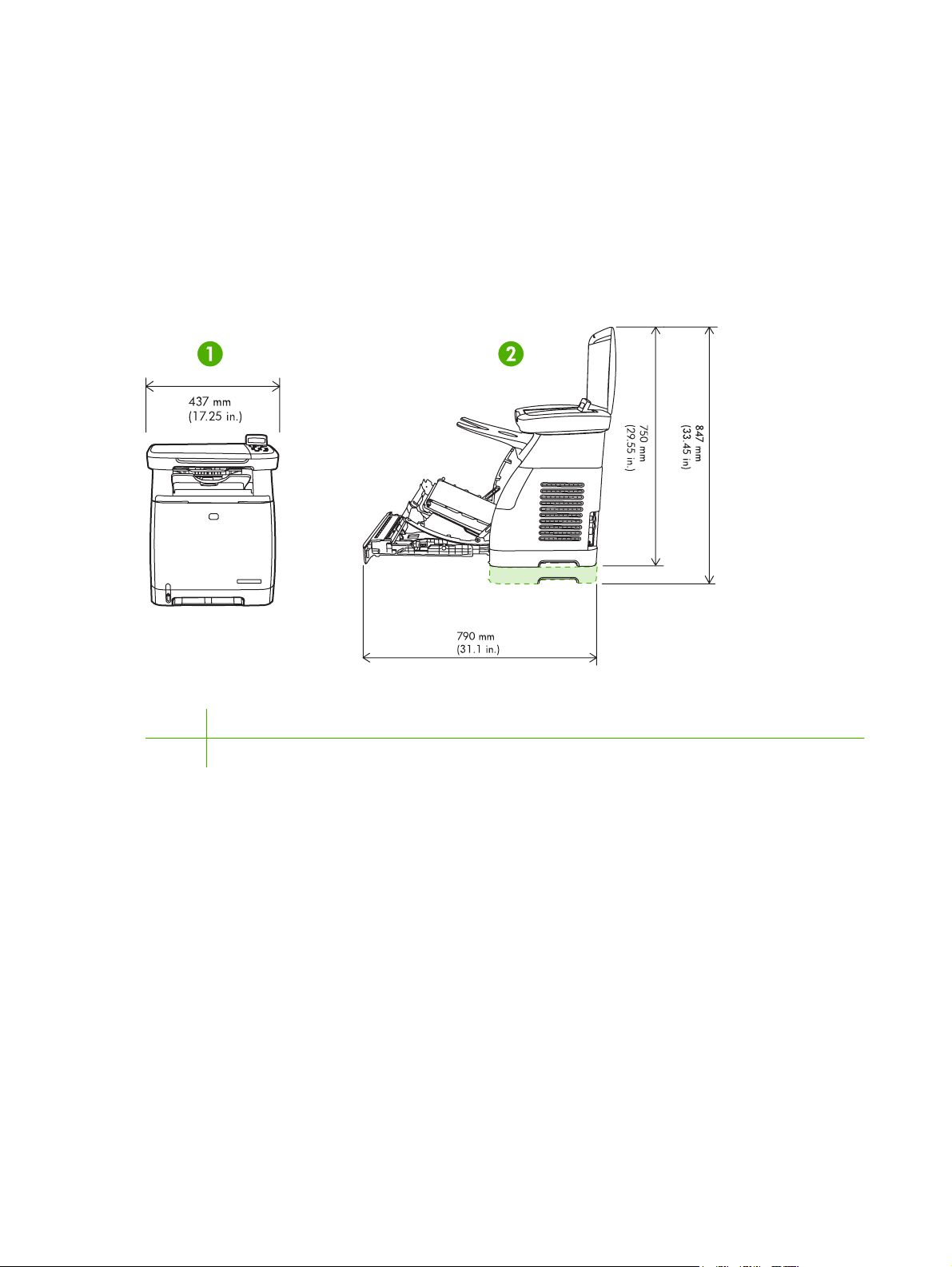
The printer must have 2 inches of space above and around it.
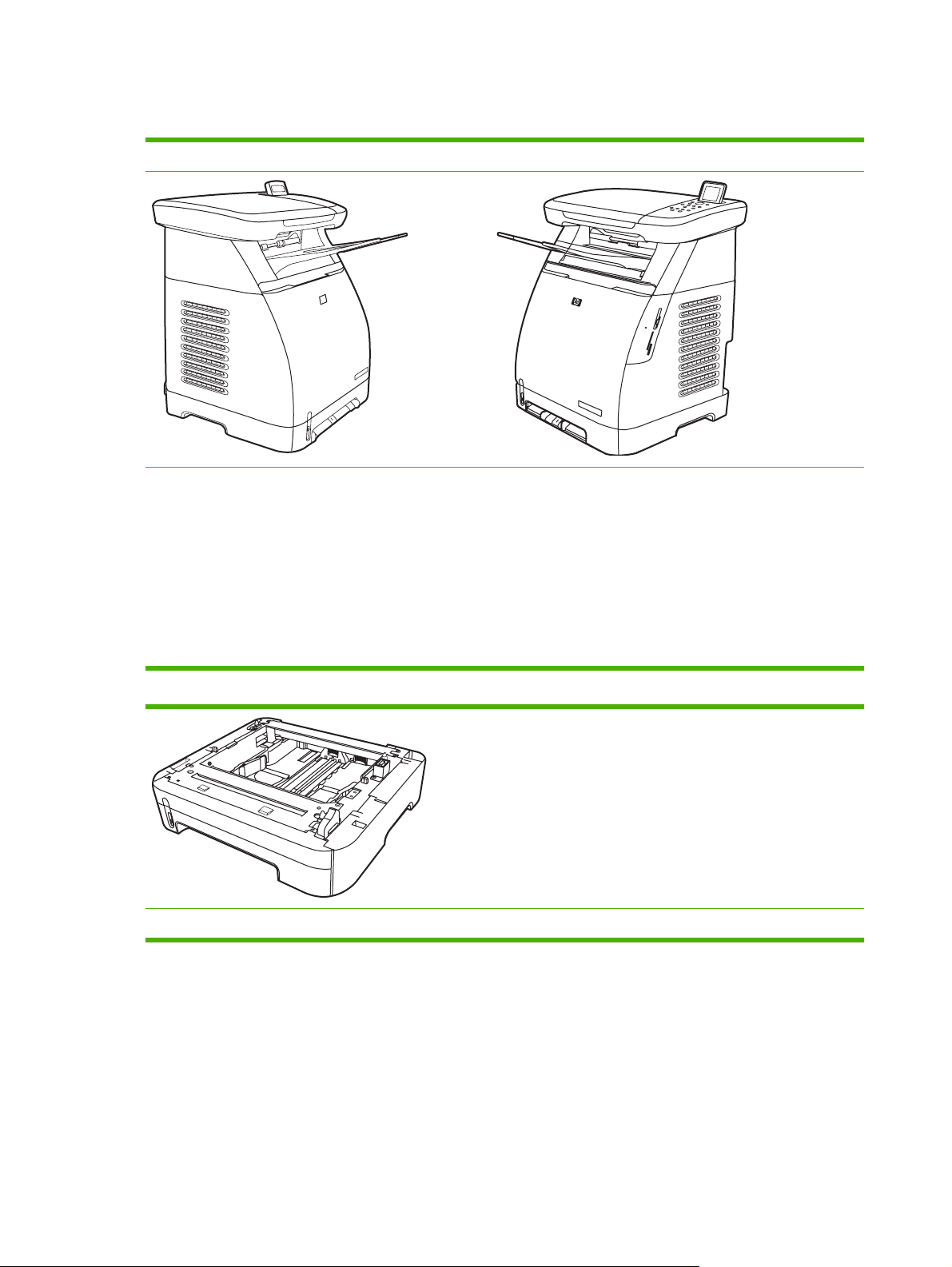
Figure 2-1 Printer dimensions
1 Front view
2 Side view
Make sure the printer is in a location that has the following:
A well-ventilated, dust-free area
●
A surface that will support up to 18 kg (40 lbs)
●
A constant temperature and humidity (Do not install near water sources, humidifiers, air
●
conditioners, refrigerators, or other major appliances.)
● A hard, level surface (not more than a 2° angle)
Make sure to keep the printer away from the following:
Direct sunlight, dust, open flames, or water
●
Direct flow of exhaust from air ventilation systems
●
Magnets and devices that emit a magnetic field
●
14 Chapter 2 Installation ENWW
Page 25

Areas subject to vibration
●
Walls or other objects. There must be enough space around the printer for proper access and
●
ventilation
Minimum system requirements
The minimum system requirements for the HP Color LaserJet CM1015/CM1017 MFP are listed below:
300 MB of free hard disk space
●
CD-ROM drive
●
USB port and USB cable
●
Requirements for PC systems
Windows 2000, XP (32-bit Home and Professional), or Server 2003
●
Pentium® II processor (Pentium III or greater recommended)
●
192 MB RAM
●
Requirements for Macintosh systems
Mac OS X V10.3 and later
●
G3 processor (G4 processor recommended)
●
128 MB RAM
●
ENWW Site preparation 15
Page 26

Package contents
Figure 2-2 Package contents on page 16 lists the package contents for the HP Color LaserJet
CM1015/CM1017 MFP.
Figure 2-2 Package contents
1 HP Color LaserJet CM1015/CM1017 MFP
2 Dust cover
3 Paper delivery tray
4 Control-panel overlays
5 Software and user documentation CD-ROM
6 Power cable
7 Getting Started Guide
16 Chapter 2 Installation ENWW
Page 27
Installing optional tray 3
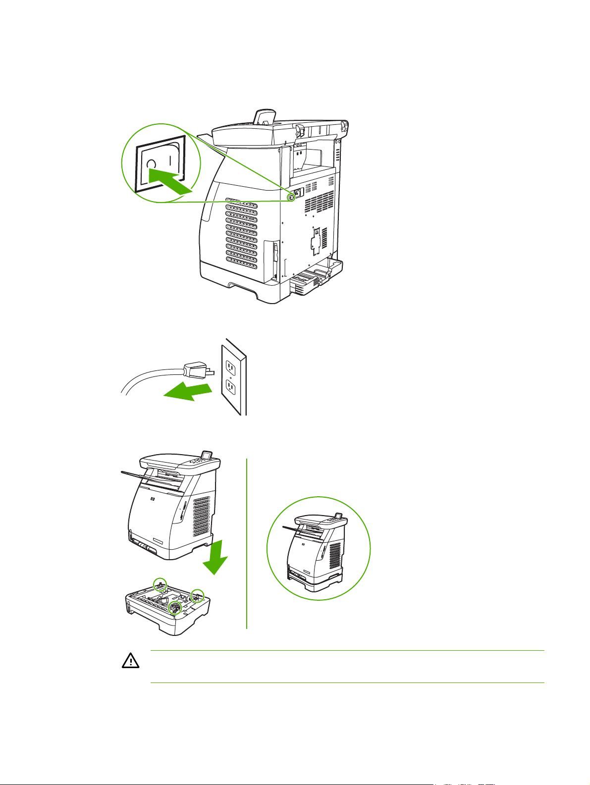
1. Turn off the power switch on the MFP.
2. Unplug the power cable.
3. Place the MFP on optional tray 3, aligning the three pegs on tray 3 with the holes on the MFP.
WARNING! The MFP weighs 18 kg (40 lbs). Always have another person assist you
when lifting the MFP.
ENWW Installing optional tray 3 17
Page 28
Installing memory DIMMs
When installing more memory for the MFP, it is possible to install a DIMM to print characters for
languages such as Chinese, or for the Cyrillic alphabet.
CAUTION Static electricity can damage DIMMs. When handling DIMMs, wear an antistatic
wrist strap, or frequently touch the surface of the DIMM antistatic package then touch bare
metal on the MFP.
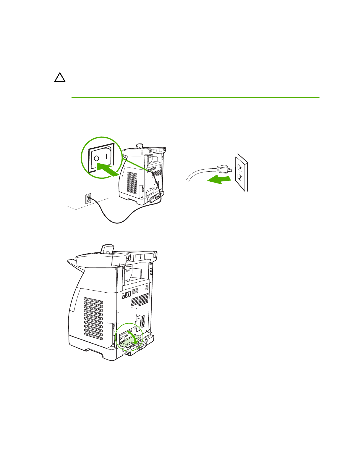
1. Print a Configuration page by pressing OK and Cancel simultaneously. (A Supplies Status may
also page print.)
2. After the Configuration page prints, turn the MFP off and disconnect the power cable.
3. On the left rear side of the MFP, open the DIMM door.
18 Chapter 2 Installation ENWW
Page 29
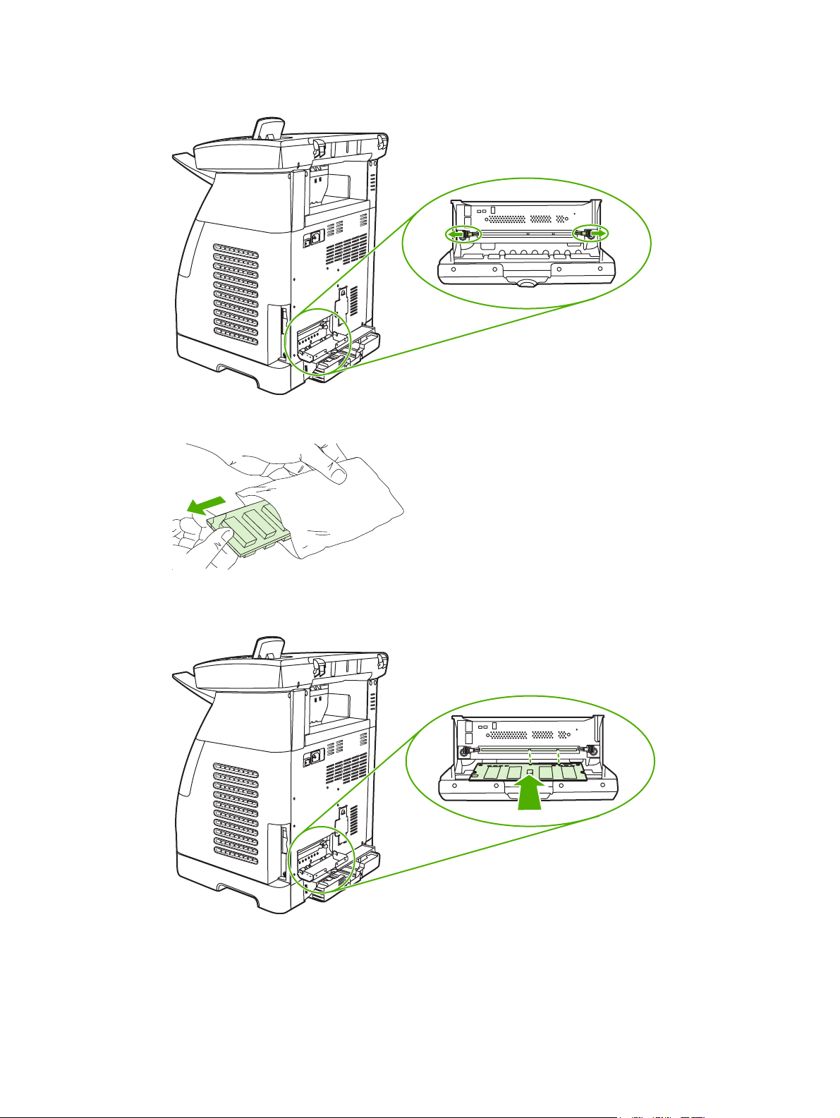
4. Release the locks on each side of the DIMM slot.
5. Remove the DIMM from the antistatic package.
6. Holding the DIMM by the edges as shown in the illustration, align the notches on the DIMM with
the DIMM slot.
ENWW Installing memory DIMMs 19
Page 30
7. Firmly press the DIMM straight into the slot. Firmly close the locks on each side of the DIMM
until they snap into place.
8. Close the DIMM door.
20 Chapter 2 Installation ENWW
Page 31

9. Reconnect the power cable and turn on the MFP.
ENWW Installing memory DIMMs 21
Page 32

22 Chapter 2 Installation ENWW
Page 33

3 Managing and maintenance
This chapter contains information about these maintenance topics:
Managing supplies
●
Cleaning the MFP
●
Calibrating the MFP
●
Management tools
●
ENWW 23
Page 34

Managing supplies
Life expectancies of supplies
The life of a print cartridge depends on the amount of toner that print jobs require. When printing text
at approximately 5% coverage, a cyan, magenta, or yellow print cartridge for the HP Color LaserJet
CM1015/CM1017 MFP lasts an average of 2,000 pages, and a black print cartridge lasts an average
of 2,500 pages. A typical business letter has 5% coverage.
Check and order supplies
Check the supplies status from the control panel by printing a Supplies Status page, or viewing the
HP ToolboxFX. Hewlett-Packard recommends that placing an order for a replacement print cartridge
when the Low message for a print cartridge first displays. For typical use, the Order message
indicates that approximately two weeks of life remains. When using a new, authentic HP print
cartridge, it is possible to obtain the following types of supplies information:
Amount of cartridge remaining
●
Estimated number of pages remaining
●
Number of pages printed
●
Other supplies information
●
NOTE If the MFP is connected to the network, it is possible to set up HP ToolboxFX to send
an e-mail notification when a print cartridge is low or is near the end of its useful life. If the
MFP is directly connected to a computer, set the HP ToolboxFX to notify you when supplies
are low.
Check supply status and order using the control panel
Do one of the following:
Check the supplies status gauges on the control panel. These gauges indicate when a print
●
cartridge is low or empty. The "?" also indicates when a non-HP print cartridge is first installed.
To print the Supplies Status page from the MFP, select Reports Menu, then Supplies Status.
●
If the supplies levels are low, reorder supplies through the local HP dealer, by telephone, or online.
http://www.hp.com/go/ljsupplies to order online.
See
Check and order supplies using HP ToolboxFX
Order supplies from HP ToolboxFX by clicking the Shop for Supplies link in the top-right of the
HP ToolboxFX window. Internet access is required to connect to the Web site.
Check and order supplies using HP Solution Center
In HP Solution Center, select the MFP. The device status page shows supplies information. To order
use the HP ToolboxFX.
24 Chapter 3 Managing and maintenance ENWW
Page 35

Storing supplies
Follow these guidelines for storing print cartridges:
Do not remove the print cartridge from its package until it is ready for use.
●
CAUTION To prevent damage, do not expose the print cartridge to light for more than a
few minutes.
Store the supply in a location where the temperature is within the recommended temperature
●
range.
Store the supply in a horizontal position.
●
Store the supply in a dark, dry location away from heat and magnetic sources.
●
Replacing and recycling supplies
When installing a new HP print cartridge, follow the instructions included on the new supply's box, or
see the Getting Started Guide.
When recycling supplies:
Place the used supply in the box in which the new supply arrived
●
Complete the enclosed return label
●
Send the used supply to HP for recycling
●
For complete information, see the recycling guide included with each new HP supply item.
HP policy on non-HP supplies
Hewlett-Packard Company cannot recommend the use of non-HP supplies, either new or
remanufactured. When they are not HP products, HP cannot influence the product design or quality.
Service or repair required as a result of using a non-HP supply is not covered under the MFP
warranty.
When inserting a supply into the MFP, the MFP displays whether or not the supply is a genuine HP
supply. When a genuine HP is inserted and that supply has reached the low state from another
HP MFP, the MFP identifies the supply as non-HP. Simply return the supply to the original MFP to
reactivate HP features and functionality.
Reset the MFP for non-HP supplies
When a non-HP print cartridge is installed, a question mark appears in the displays above the
cartridge that is non-HP. To print with this supply press OK the first time this non-HP supply is
installed. The status gauges do not indicate when this type of supply is low or empty.
CAUTION The MFP may not stop printing with non-HP supplies. MFP damage can occur if
the MFP prints with an empty print cartridge.
ENWW Managing supplies 25
Page 36

HP anti-counterfeit supplies Web site
Visit the HP anti-counterfeit supplies Web site at http://www.hp.com/go/anticounterfeit if the supplies
status gauges or HP ToolboxFX indicates that the print cartridge is not an HP print cartridge and you
think that it is genuine.
26 Chapter 3 Managing and maintenance ENWW
Page 37

Cleaning the MFP
During the printing process, paper, toner and dust particles can accumulate inside the MFP. Over
time, this buildup can cause print-quality problems such as toner specks or smearing. This MFP has
a cleaning mode that can correct and prevent these types of problems.
Clean the paper path using HP ToolboxFX
NOTE Use the following procedure to clean the paper path using the HP ToolboxFX. To
clean the engine when the computer is running an operating system that does not support
HP ToolboxFX, browse to the \UTIL\CLEANPAGE directory on the MFP CD-ROM for
instructions on cleaning the paper path.
1. Ensure the MFP is turned on and in the Ready state.
2. Open HP ToolboxFX.
3. In the menu tree for the HP Color LaserJet CM1015/1017 MFP, expand the Help folder, and
then click the Troubleshooting page.
4. In the Cleaning Page section, click Print Page. A cleaning page prints.
5. Insert the cleaning page in tray 1 with the printed side up.
6. In the Cleaning Page section, click Clean.
7. Follow the instructions on the control panel.
Clean the scanner glass
Dirty glass from debris may cause scan and copy image defects.
1. Turn device off, unplug the power cord from the electrical socket, and raise the lid.
ENWW Cleaning the MFP 27
Page 38

2. Clean the glass by using a soft lint-free cloth that has been moistened with nonabrasive glass
cleaner.
CAUTION Do not use abrasives, acetone, benzene, ammonia, ethyl alcohol, or carbon
tetrachloride on any part of the device; these can damage the device. Do not place
liquids directly on the glass. They might seep under it and damage the device.
3. To prevent spotting, dry the glass using a soft lint-free cloth.
28 Chapter 3 Managing and maintenance ENWW
Page 39

Calibrating the MFP
The MFP automatically self-calibrates, but calibration settings can be manually adjusted by using the
HP ToolboxFX.
Environmental differences or aging print cartridges might cause fluctuations in image density. The
MFP accounts for this with image stabilization control. The MFP automatically calibrates at various
times to maintain the highest level of print quality. Also request a calibration by using the
HP ToolboxFX.
The MFP does not interrupt a print job to calibrate. It waits until the job is complete before calibrating
or cleaning. While the MFP is calibrating, it pauses printing for the time that is required to complete
the calibration.
Calibrate the MFP from the front control panel.
1. Press Menu.
2. Press the navigation arrows until the display reads System setup.
3. Press OK.
4. Press the navigation arrows until the display reads Print quality.
5. Press OK.
6. Press the navigation arrows until the display reads Calibrate color.
7. Press OK.
8. Press the navigation arrows until the display reads Calibrate now.
9. Press OK.
10. Press OK to confirm Calibrate now.
Calibrate the MFP from HP ToolboxFX
1. Open HP ToolboxFX in one of these ways:
On the desktop, double-click the HP ToolboxFX icon.
●
On the Start menu, point to Programs, point to HP, point to HP Color LaserJet
●
CM1015/1017 MFP Series, and click HP ToolboxFX.
2. In the menu tree for the HP Color LaserJet CM1015/1017 MFP, expand the System Settings
folder, and then click the Print Quality page.
3. In the Color Calibration section, click Calibrate.
ENWW Calibrating the MFP 29
Page 40

Management tools
This printer comes with several software tools that help you monitor, troubleshoot problems with, and
maintain the printer. Information about using these tools is in the following sections:
Special pages
●
Menu map
●
HP ToolboxFX
●
Embedded Web server
●
Special pages
Special pages reside within the MFP memory. These pages help diagnose and solve MFP problems.
NOTE If the MFP language was not correctly set during installation, set the language
manually so that the pages print in one of the supported languages. Change the language by
using the control panel or the embedded Web server.
Demo page
To print the Demo page, press Scan To and Start Scan simultaneously. A demo page can also be
printed from the HP ToolboxFX.
Configuration page
The Configuration page lists the current MFP settings and properties. Print a Configuration page
from the MFP or the HP ToolboxFX.
To print the Configuration page from the control panel
1. Press Menu.
2. Press the navigation arrows to select Reports.
3. Press OK.
4. Press the navigation arrows to select Configuration report.
5. Press OK to print the Configuration report page.
30 Chapter 3 Managing and maintenance ENWW
Page 41

1. Product Information. Displays basic information about the MFP, such as the product name
and the serial number.
2. Memory. Lists memory-related information, such as the total memory that is installed.
3. Paper Settings. Lists information about the media type for each tray and about the type
settings for all the media that the MFP supports.
4. Copy Settings. Lists current MFP default copy information.
5. Product Settings. Lists information about the MFP, including the language and the company
name.
6. Installed Personalities and Options. Contains current MFP font, DIMM memory, and memory
card information.
7. Print Settings. Displays MFP printer settings, such as color options, copies, and jam recovery
information.
8. Photo Settings (CM1017 only). Displays default photo information such as image size, number
of copies, and output color.
Supplies Status page
The Supplies Status page lists the remaining life of HP print cartridges. It also lists the estimated
pages remaining, number of pages printed, and other supplies information. A Supplies Status page
can be obtained from the MFP or the HP ToolboxFX.
ENWW Management tools 31
Page 42

To print the Supplies Status page from the control panel
1. Press Menu.
2. Press the navigation arrows to select the Reports menu.
3. Press OK.
4. Press the navigation arrows to select Supplies Status page.
5. Press OK to print the Supplies Status page.
NOTE Supplies information is also available through the HP ToolboxFX.
1. Print cartridge area. Displays a section for each of the print cartridges and provides
information about HP print cartridges. This information includes the part number for each print
cartridge, whether each print cartridge is low, and the life remaining for each print cartridge,
which is expressed as a percentage, as a graphic, and as the estimated number of pages
remaining. This information might not be provided for non-HP supplies. In some cases, if a nonHP supply is installed, an alert message displays instead.
2. Ordering Information. Displays basic information about how to order new HP supplies.
3. Return & Recycling. Displays a link to the Web site that contains information about recycling.
Networking page (CM1017 only)
The Networking report option prints a Network configuration report.
32 Chapter 3 Managing and maintenance ENWW
Page 43

To print the Network configuration report from the control panel
1. Press Menu.
2. Press the navigation arrows to select the Reports menu.
3. Press OK.
4. Press the navigation arrows to select Network report.
5. Press OK to print the Network Configuration page.
1. Network Hardware Configuration. Displays current MFP hardware configuration such as
status, hardware address, firmware datecode, link speed information, and connection timeout.
2. Enabled Features. Displays password, network protocol, memory card, LPD printing, Bonjour,
and HPSLP settings.
3. TCP/IP. Displays host, domain, and printer name, and other IP information.
4. SNMP. Displays status, version, and set/get community names.
5. Network Statistics. Displays packet and collision information.
Fonts pages
The Fonts pages provide lists of the available fonts on the MFP, including HP postscript level 3 fonts,
PCL fonts, and PCL6 fonts.
ENWW Management tools 33
Page 44

To print a fonts page from the control panel
1. Press Menu.
2. Press the navigation arrows to select the Reports menu.
3. Press OK.
4. Press the navigation arrows to select PS font list, PCLXL font list, or PCL font list.
5. Press OK to print the selected Fonts page.
Usage page
The Usage Page provides information on the number and types of pages printed by the MFP.
To print a usage page from the control panel
1. Press Menu.
2. Press the navigation arrows to select the Reports menu.
3. Press OK.
4. Press the navigation arrows to select the Usage page.
5. Press OK to print the Usage page.
Service page
The Service page provides information about paper types, copy settings, and miscellaneous settings.
To print a Service page from the control panel
1. Press Menu.
2. Press the navigation arrows to select the Reports menu.
3. Press OK.
4. Press the navigation arrows to select the Service page.
5. Press OK to print the Service page.
Menu map
The menu map lists the menu structure for each option available on the control panel.
To print a menu map
1. Press Menu.
2. Press the navigation arrows to select the Reports menu.
3. Press OK.
4. Press the navigation arrows to select Menu structure.
5. Press OK to print the Menu map.
34 Chapter 3 Managing and maintenance ENWW
Page 45

HP ToolboxFX
HP ToolboxFX is a software program that performs these tasks:
Checks the MFP status.
●
Configures the MFP settings.
●
Displays problem solving information.
●
Displays online documentation.
●
You can open HP ToolboxFX when the MFP is directly connected to the computer or when it is
connected to the network.
NOTE HP ToolboxFX is not supported for Windows Server 2003 or Macintosh operating
systems.
NOTE Internet access is not required to open and use the HP ToolboxFX.
Open HP ToolboxFX
Open HP ToolboxFX in one of the following ways:
In the Windows program group entry and the system tray icon, double-click HP ToolboxFX icon.
●
On the Windows Start menu, click Programs (or All Programs in Windows XP), click HP, then
●
click HP ToolboxFX.
The HP ToolboxFX software contains the following sections:
Status on page 36
●
Alerts on page 37
●
Help on page 37
●
System settings on page 38.
●
Print Settings on page 40
●
Network settings on page 41
●
ENWW Management tools 35
Page 46

Status
The HP ToolboxFX Status folder contains links to the following main pages:
Device Status. View MFP status information. This page indicates MFP conditions such as a
●
jam or an empty tray. When a problem is corrected with the MFP, click Refresh button to
update the MFP status.
Supplies Status Page. View detailed supplies status such as the estimated percent of toner
●
remaining in the print cartridge and the number of pages that have been printed with the current
print cartridge. This page also has links to order supplies and to find recycling information.
Device Configuration. View a detailed description of the current MFP configuration, including
●
the amount of memory installed and whether optional trays are installed.
● Network config. View a detailed description of the current network configuration, including the
IP address and network status.
Print Info Pages. Print the Configuration page and various other information pages that are
●
available for the MFP, such as the Supplies Status page and the Demo page.
Event Log. View a history of MFP errors. The most recent error is at the top of the list.
●
Event log
The Event log is a four-column table where the MFP events are logged for reference. The log
contains codes that correspond to the error messages that appears on the MFP control-panel
display. The number in the Page Count column specifies the total number of pages that the MFP had
printed when the error occurred. The Event log also contains a brief description of the error.
36 Chapter 3 Managing and maintenance ENWW
Page 47

Alerts
The HP ToolboxFX Alerts tab folder contains links to the following main pages:
Set Up Status Alerts. Set up the MFP to send pop-up alerts for certain events, such as low
●
toner levels.
Set Up Email Alerts. Set up the MFP to send e-mail alert messages for certain events, such as
●
low toner levels.
Set up status alerts
Use HP ToolboxFX to set up the MFP so that it issues pop-up alerts to the computer when certain
events occur. Events that trigger alerts include jams, low levels of toner in HP print cartridges, nonHP print cartridge in use, empty input trays, and specific error messages.
Select the pop-up format, the system tray icon format, the desktop format, or all three for the alerts.
The pop-up alerts only appear when the MFP is printing from the computer on which you set up the
alerts.
NOTE Click Apply to make the changes take effect.
Set up e-mail alerts
Use HP ToolboxFX to configure a maximum of two e-mail addresses to receive alerts when certain
events occur. It is possible to specify different events for each e-mail address. Enter the information
for the e-mail server that will send out the e-mail alert messages for the MFP.
NOTE Click Apply to make the changes take effect.
Help
The HP ToolboxFX Help folder contains links to the following main pages:
Troubleshooting. Print troubleshooting pages, clean the MFP, and display Microsoft Office
●
Basic Colors.
How Do I. View the How Do I? Help.
●
Animated Demonstrations
●
User Guide. View information about the MFP usage, warranty, specifications, and support. The
●
user guide is available in both HTML and PDF format.
ENWW Management tools 37
Page 48

System settings
The HP ToolboxFX System Settings folder contains links to the following main pages:
Device information. View information about the MFP, such as the description and a contact
●
person.
Paper handling. Change the MFP paper-handling settings, such as default paper size and
●
default paper type.
Print quality. Change the MFP print-quality settings.
●
● Print density. Change the print density settings, such as contrast, highlights, midtones, and
shadows.
Paper types. Change the MFP mode settings for each media type, such as letterhead,
●
prepunched, or glossy paper.
System Setup. Change the MFP system settings, such as MFP language and jam recovery.
●
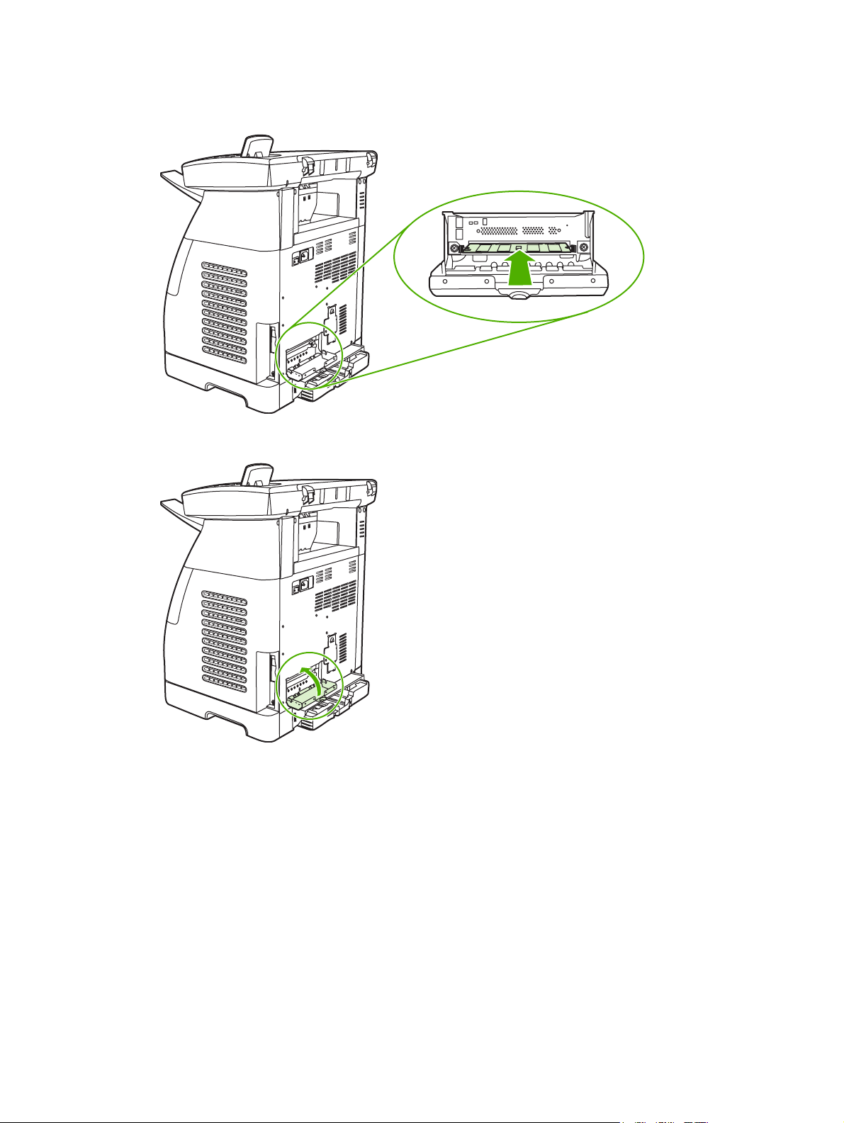
Service. Gain access to various procedures required to maintain the MFP.
●
Device Polling. The HP ToolboxFX periodically communicates with your device to determine
●
device status and enable features.
Save and restore settings. Save the current MFP settings to a file on the computer. Use this
●
file to load the same settings onto another printer or MFP to restore these settings to this MFP
at a later time.
Password. Set a password for the MFP. If set, the password is required to change any Network
●
Settings configuration items.
Device information
Save the HP ToolboxFX Device information for future reference about the MFP. The information that
is typed in these fields appears on the Configuration page. It is possible to type any character in each
of these fields.
NOTE Click Apply to make the changes take effect.
38 Chapter 3 Managing and maintenance ENWW
Page 49

Paper handling
Use the HP ToolboxFX paper-handling options to configure the default settings. These are the same
options that are available on the System setup and Paper setup menus on the control panel.
Three options accommodate handling print jobs when the product is out of media:
Select Wait for paper to be loaded.
●
Select Cancel from the Paper out action drop-down list to cancel the print job.
●
Select Override from the Paper out time drop-down list to send the print job to another paper
●
tray.
The Paper out time field specifies how long the MFP waits before acting on your selections. It is
possible to specify from 0 to 3600 seconds.
NOTE Click Apply to make the changes take effect.
Print quality
Use the HP ToolboxFX print-quality options to improve the print job appearance. These same
options are available on the System setup and Print quality menus on the control panel.
These options control print quality.
Color Calibration.
●
Power On Calibration
●
Calibration Timing
●
Calibrate Now
●
Grayscale Printing.
●
Grayscale printing options Description
Resolution Select 600 resolution for average print jobs and Fast Res
REt Choose REt which HP provides for improved print quality.
1200 for higher-quality print jobs. Select ProRes 1200 for
the highest-quality print job, but a longer printing time.
NOTE Click Apply to make the changes take effect.
Print density
The print density settings control making fine adjustments to the density (amount) of cyan, magenta,
yellow, and black toner in images, pages, and documents.
Print density settings Description
Contrasts Contrast is the density difference between light (highlight)
and dark (shadow) colors. To increase the difference
ENWW Management tools 39
Page 50

Print density settings Description
between light and dark colors (equivalent to a negative
highlight adjustment and a positive shadow adjustment), use
a positive contrast setting. To decrease the difference
between light and dark colors (equivalent to a positive
highlight adjustment and a negative shadow adjustment),
use a negative contrast setting.
Highlights Highlight colors are colors near white. To make highlight
Midtones Midtone colors are about halfway between white and solid
Shadows Shadow colors are colors near solid density. To make
colors darker, use a positive highlight setting, and to make
highlight colors lighter use a negative highlight setting. This
adjustment does not affect midtone or shadow colors.
density. To make midtone colors darker, use a positive
midtone setting, and to make midtone colors lighter use a
negative highlight setting. This adjustment does not affect
highlight or shadow colors.
shadow colors darker, use a positive shadow setting, and to
make shadow colors lighter use a negative shadow setting.
This adjustment does not affect highlight or midtone colors.
Paper types
Use these HP ToolboxFX Paper types options to configure print modes that correspond to the
various media types. When selecting Restore modes, all of the modes are reset to the factory
settings.
NOTE Click Apply to make the changes take effect.
System setup
Use the HP ToolboxFX system settings options to configure miscellaneous print settings. These
settings are not available from the control panel.
NOTE Click Apply to make the changes take effect.
Service
During the printing process, paper, toner, and dust particles can accumulate inside the MFP. Over
time, this buildup can cause print-quality problems such as toner specks or smearing. HP ToolboxFX
provides an easy method for cleaning the paper path.
Device Polling Page
The HP ToolboxFX periodically communicates with your device to determine device status and
enable features. Use the Polling Page to turn off pop-up alerts and the Scan To and Start Scan
buttons located on the device.
Print Settings
The HP ToolboxFX Print Settings folder contains links to the following main pages:
40 Chapter 3 Managing and maintenance ENWW
Page 51

Printing
Use the HP ToolboxFX printing settings options to configure the settings for all print functions. These
are the same options that are available on the Print settings menu on the control panel.
NOTE Click Apply to make the changes take effect.
PCL5c
Configure these PCL5c settings:
Font number
●
Font pitch
●
Font point size
●
Symbol set
●
Append CR to LF
●
Form length
●
PostScript
Use the PostScript option when using the PostScript print personality. When the Print PostScript
error option is turned on, the PostScript error page automatically prints when PostScript errors occur.
NOTE Click Apply to make the changes take effect.
Memory card (HP Color LaserJet CM1017 MFP only)
Use the three HP ToolboxFX memory card options to configure print settings when using memory
cards.
Enable memory cards. Enable or disable memory-card functionality.
●
Photo image size. Select the size photos to print from the drop-down list.
●
Photo number of copies. Type the number of copies from 0 to 99 to print for each image.
●
Photo output color. Select either Color or Monochrome from the drop-down list.
●
Click Apply to save the settings.
Network settings
The network administrator can use the HP ToolboxFX Network Settings folder to control the
network-related MFP settings when it is connected to an IP-based network.
The settings are:
IP Configuration
●
Advanced
●
ENWW Management tools 41
Page 52

SNMP
●
Network Summary
●
NOTE For more information about network settings, see the HP Color LaserJet CM1015/
CM1017 MFP User Guide.
Other links found in HP ToolboxFX
Internet access is required to use any of these links.
HP Instant Support™. Connects to the HP Web site to help find solutions. This service
●
analyzes the MFP error log and configuration information to provide diagnostic and support
information specific to the MFP.
Product Registration. Click to connect with the HP Web site to register the product.
●
Product Support. Connects to the support site for the HP Color LaserJet CM1015/CM1017
●
MFP to search for help regarding general topics.
Embedded Web server
The embedded Web server displays MFP and network status and manages printing functions from
the computer instead of the MFP control panel. The embedded Web server allows you to perform the
following actions:
View MFP status information.
●
Set the type of paper loaded in each tray.
●
Determine the remaining life on all supplies and order new ones.
●
● View and change tray configurations.
View and change MFP settings.
●
View and print internal information pages.
●
View and change network configuration.
●
When the MFP is connected to the network, the embedded Web server is automatically available.
Access the embedded Web server from any supported browser.
The embedded Web server supports these browsers for Windows:
Windows Macintosh
Microsoft Internet Explorer 6.0 and later Safari 1.2 or later
Netscape 7.0 or later Netscape 7.0 or later
Opera 7.0 or later Opera 7.0 or later
Firefox 1.0 or later Firefox 1.0 or later
Mozilla 1.6 or later Mozilla 1.6 or later
42 Chapter 3 Managing and maintenance ENWW
Page 53

The embedded Web server works when the MFP is connected to an IP-based network. The
embedded Web server does not support IPX-based or AppleTalk MFP connections. Internet access
is not required to open and use the embedded Web server.
Open the embedded Web server
To open the embedded Web server, open a supported Web browser and type the device IP address
in the address/URL field. (To find the IP address, print a Configuration page.)
NOTE If there is no access to the embedded Web server using the IP address, try using the
host name.
NOTE After the URL is open, bookmark it for easy return.
The embedded Web server has four tabs that contain MFP settings and information:
Status tab
●
System tab
●
Print tab
●
Networking tab
●
Status tab
The Status tab consists of the following pages:
Device Status. Displays the remaining life of HP supplies. Zero percent (0%) indicates that a
●
supply is empty.
Supplies Status. Displays the remaining life of HP supplies. , along with supplies serial
●
numbers and usage information. To order new supplies, click Order Supplies in the top-right
portion of the page. Internet access is required to visit any Web site.
Device Configuration. Displays the product information found on the MFP Configuration page,
●
such as page counts, print settings, and paper options.
Network Summary. Displays network hardware configuration, enabled network features, TCP/
●
IP settings, and other network-related information.
Print Info Pages. Provides a remote way to print a PCL font list, PCL6 font list, PS font list, or
●
Supplies page.
Event Log. Displays the MFP event log.
●
System tab
This tab allows MFP configuration from a computer. The System tab can be password protected. If
this MFP is networked, always consult with the MFP administrator before changing settings on this
tab.
The System tab contains these pages:
Device Information. Configure device naming and ownership information from this page.
●
Paper Handling. Configure paper handling settings from this page.
●
ENWW Management tools 43
Page 54

Print Quality. Configure color calibration and optimize settings.
●
Print Density. Configure print density settings including contrast, highlights, midtones, and
●
shadows.
Paper Types. Configure paper types
●
System Setup. Configure the jam recovery, auto continue, I/O timeout, cartridge-low threshold,
●
and MFP language settings.
Print tab
This tab allows print configuration from a computer.
The Print tab contains these pages:
Printing. Configure default print settings.
●
PCL5c. Configure PCL5c print settings.
●
PostScript. Configure whether PostScript errors are printed.
●
Memory Card (HP Color LaserJet CM1017 only). Configure memory-card defaults.
●
Networking tab
This tab allows the network administrator to control MFP network-related settings when the MFP is
connected to an IP-based network.
IP Configuration. Configure IP settings.
●
Advanced. Enable network features such as SLP Config, DHCP, BOOTP, and AutoIP.
●
Bonjour. Enable Bonjour.
●
SNMP. Set SNMP protocols.
●
Network Summary. Displays network hardware configuration, enabled network features, TCP/
●
IP settings, and other network-related information.
Password. Set or change the administrator password.
●
44 Chapter 3 Managing and maintenance ENWW
Page 55

4 Operational theory
This chapter contains information about the following topics:
Engine control system
●
Image formation system
●
Pickup and feed system
●
Scanner system
●
Service-only tools
●
ENWW 45
Page 56

Engine control system
Basic sequence of operation
The operational sequence of the printer is controlled by the microcomputer on the DC controller
printed circuit assembly (PCA). The purposes of each period, from power-on until the main motor
stops after the completion of printing, are listed below.
Table 4-1 Basic operational sequence
Period Purpose Remarks
WAIT (wait period) From power-on until the end
of the main motor initial drive.
STBY (standby period) From the end of WAIT or
LSTR until the input of print
command from the
formatter. Or, from the end
of LSTR until power-off.
INTR (initial rotation period) From the input of print
command from the formatter
until the pick-up solenoid is
turned on.
PRINT (print period) From the end of INTR until
the developing high-voltage
is off.
LSTR (last rotation period From the developing high-
voltage off until the main
motor stops rotating.
To clear the drum surface
potential and to clean the
ETB.
To keep the printer ready to
print.
To stabilize the
photosensitive drum
sensitivity for print
preparation.
To form the image on the
photosensitive drum based
on the VIDEO signals input
from the formatter, and to
transfer the toner image
onto paper.
To deliver the last page
completely. Also used to
clean the ETB.
Detects whether or not the
print cartridge is installed.
The printer enters INTR after
the end of LSTR, when the
print command is input from
the formatter.
The engine control system coordinates all printer functions. It drives the laser/scanner system, the
image formation system, and the pickup and feed system. The engine control system contains the
following components:
DC controller PCA
●
Low-voltage power supply unit
●
High-voltage power supply PCA
●
46 Chapter 4 Operational theory ENWW
Page 57

Figure 4-1 Engine control system
Power-on sequence
The power-on sequence is for the purpose of the printer initialization and checking for possible
malfunctions.
The following is the sequence from when the printer is turned on until it enters STBY mode.
1. Power on
2. Central processing unit (CPU) initialization on the DC controller
3. ASIC initialization on the formatter
4. Video interface communication start, scanner initialization and calibration
5. Residual paper check by each sensor signaling paper presence
6. Initial drive for main motor, pickup motor, and fuser/delivery motor
7. Fuser heater initial drive by controlling fuser temperature targeting for 100°C
8. Initial drive for laser scanner motor
9. Failure/Abnormality check
Detect scanner failure
●
Fuser failure
●
Door open during the above periods
●
10. Communication with memory tag
11. Cartridge presence detection
Motors and fans
The DC controller PCA controls four motors.
ENWW Engine control system 47
Page 58

The specifications of each motor are listed in the following table.
Table 4-2 Motor specifications
Name Purpose Type Direction of
Motor Main motor (M1) Drive ETB belt,
Fuser/delivery
motor (M2)
Pickup motor (M3) Drive pickup roller
Fan (FM1) Circulate air
photosensitive
drum and
developing cylinder
Drive fuser
pressure roller,
delivery roller and
automatic release
of fuser pressure
and registration
roller
around cartridge
DC motor CW Yes
Stepping motor CW/CCW No
Stepping motor CW No
DC motor — Yes
rotation
Failure detection
Main-motor failure detection (59.x errors)
The DC controller CPU stops the printer and notifies the formatter of the error status when it detects
the following motor-failure conditions:
Main motor startup abnormality: The motor does not get to the target rotation speed within a
●
specified time.
Main motor rotation abnormality: After the target rotation speed is achieved, this speed is not
●
maintained.
Fan motor failure detection
The CPU detects a fan-motor failure and notifies the formatter when it encounters the following
condition: The FAN LOCK signal (FANLCK) is “H” for approximately 10 seconds or longer during fan
motor rotation.
48 Chapter 4 Operational theory ENWW
Page 59

Image formation system
The image-formation system, which forms a toner image on media, consists of several
interdependent systems:
Electrostatic latent-image formation
●
● Developing
Transfer
●
Fuser
●
Drum cleaning
●
The MFP includes four print cartridges that contain the toner that is used to create the image on the
media. Toner is applied in the following order, using only the colors necessary for a specific image:
magenta (M), cyan (C), yellow (Y), and black (Bk).
The following figure illustrates the image formation system.
Figure 4-2 Image formation system
ENWW Image formation system 49
Page 60

Pickup and feed system
The pickup and feed system, which picks up and feeds paper, consists of the various feed rollers.
This printer has two pickup sources (the cassette and the single-sheet priority feed slot) and one
delivery source (the face-up tray). The following components are part of the pickup and feed system:
Manual feed slot paper sensor (SR3): detects the presence of paper in the single-sheet priority
●
feed slot
Cassette paper sensor (SR2): detects the presence of paper in the cassette
●
DC controller controls the following to drive each feed roller:
●
Main motor (M1)
●
● Fuser/delivery motor (M2)
Pickup motor (M3)
●
Solenoid (SL1)
●
Solenoid (SL2)
●
Solenoid (SL3)
●
Photo sensors:
●
● SR1, SR4, and SR5 on the paper transport path detect the arrival and passage of paper
SR9 detects the fuser pressure roller alienation in the fuser
●
SR8 detects the paper width
●
The figure below illustrates the motors, solenoids, and sensors.
NOTE There is a short pause before the paper is picked up.
50 Chapter 4 Operational theory ENWW
Page 61

Figure 4-3 Paper pickup and feed system
1 Face-up delivery roller #1
2 Face-up delivery roller #2
3 Fusing/delivery motor
4 Fusing pressure roller
Manual feed slot pickup mechanism
This mechanism picks up one sheet of paper only that is inserted into the single-sheet priority feed
slot and then into the printer. This printer does not have a pickup roller in the single-sheet priority
feed slot. Instead of a pickup roller, the registration roller picks up paper. The presence of paper in
the single-sheet priority feed slot is detected by the single-sheet priority feed slot paper sensor
(SR3). The following is the operational sequence of the single-sheet priority feed slot pickup.
1. If paper is set into the single-sheet priority feed slot during STBY mode, the single-sheet priority
feed slot paper sensor (SR3) detects it.
2. When the paper is detected, the DC controller drives the pickup motor (M3) for 5 seconds. The
paper is fed approximately 5 mm (0.2 inch) and is then caught by the registration roller.
3. After the above operational sequence, the paper is fed by the drive of the registration roller.
ENWW Pickup and feed system 51
Page 62

Paper feed mechanism
This mechanism feeds one sheet of picked-up paper to the fuser. There is a paper length sensor in
the paper transport path to prevent temperature rise at the end of the fuser. It detects paper lengths
shorter than 190 mm (7.5 inches). The following is the operational sequence of paper feed.
1. Paper skew is corrected by the registration shutter when the paper is fed into the printer.
2. Toner is transferred to the paper from the photosensitive drum and then the paper is fed to the
fuser/delivery stage.
Skew correction by the registration shutter
If the paper fed into the printer is skewed, it will be adjusted when it hits the registration shutter.
Figure 4-4 Skew correction
52 Chapter 4 Operational theory ENWW
Page 63

Jam detection
This printer is provided with the following paper detection sensors to detect the presence of paper
and whether or not the paper feed is operating normally.
Registration paper sensor (SR1)
●
Pre-fuser paper sensor (SR5)
●
Fuser delivery paper sensor (SR4)
●
The CPU on the DC controller determines a paper jam by checking whether or not paper is present
at the sensor at the check timing. The check timing is stored in the memory of the CPU. If the CPU
determines a jam, it stops the print operation and notifies the formatter of a jam occurrence.
Printed circuit assembly locations
The following illustration shows the locations of the printed circuit assemblies.
ENWW Pickup and feed system 53
Page 64

Figure 4-5 Location of printed circuit assemblies
1 Formatter PCA
2 DC controller PCA
3 Control-panel PCA
4 Memory-card PCA
250-sheet tray solenoid and printed circuit locations
The following illustration shows the locations of the 250-sheet tray solenoid and printed circuit
assembly.
54 Chapter 4 Operational theory ENWW
Page 65

Figure 4-6 Location of 250-sheet tray solenoid and printed circuit assembly
1 Paper feeder PCA
2 Paper feeder pickup solenoid
3 Paper-pickup feeder unit
ENWW Pickup and feed system 55
Page 66

Scanner system
The flatbed image scanner captures an electronic image of the document on the glass. The scanner
does this by illuminating the document with LEDs (red, green, and blue) and capturing the image in
the image sensor to create an electronic format of the document. The flatbed scanner consists of
three main elements
CIS scanner. The CIS (contact image sensor) scanner captures an image using the device's
●
optical path. Red, green, and blue LEDs sequentially illuminate a small strip of the document
(often called a raster line), and the optical system captures each color in a single row of CCD
sensors that cover the entire page width. Because only one color is captured for each line per
exposure, the three colors are recombined electronically to create the full color image. For
monochromatic scans or copies, all three LEDs are illuminated to create a white light for the
scan so the raster line can be captured in one exposure.
Mechanical carriage drive. The carriage drive moves the CIS scan head along the document
●
length to create the image. In this device, a small DC motor with an optical encoder creates this
motion. The speed of the carriage drive is proportional to the scan resolution (300 ppi is much
faster than 1200 ppi) and also proportional to the type of scan (color scans are three-times
slower than monochromatic scans). A 1200 ppi color scan moves so slowly that the product
may appear to not be working, whereas a monochromatic copy scan moves at fifty–times that
speed and will be a little noisy.
Image processing system (formatter). The formatter processes the scanner data into either a
●
copy or a scan to the computer. For copies, the image data is sent directly to the printer without
being transmitted to the computer. Depending on user selections for the copy settings, the
formatter enhances the scanner data significantly before sending it to the printer. Image data is
captured at 300 ppi for copies and is user selectable for scans to the computer. Each pixel is
represented by 8 bits for each of the three colors (256 levels for each color), for a total of 24 bits
per pixel (24-bit color).
Scanner power-on sequence of events
When the device is turned on, it performs the following tests:
Motor test. The device moves the motor left and right to confirm operation. It reports a scanner
●
error 12 if no motion is detected in the motor encoder system.
Wall find. The scan carriage moves slowly to the right while watching an encoder on the
●
carriage motor to determine when the carriage has found the right side wall or stop. This
enables the device to identify the document origin (position of the original). It reports a scanner
error 13 if this process fails.
LED check. The device moves the carriage to the white calibration label under the right side of
●
the flatbed image scanner, and it verifies that the minimum and maximum response is
acceptable. It reports a scanner error 14 if the response is unacceptable.
Home find. The scan carriage uses the optical scanner to find physical reference features that
●
relate to the document origin at the right side of the image glass. This process ensures accurate
location of the first document pixels so that the user documents will have an accurate placement
of the image on scans and copies. It reports a scanner error 6 message if the reference features
are not found.
Calibration. This test, also known as scanner color calibration, enables the device to identify
●
the black and white on every pixel in the CCD. Calibration occurs in two major processes: a
broad (analog) adjustment of all pixels to bring them into the target output range, and a pixel-by-
56 Chapter 4 Operational theory ENWW
Page 67

pixel adjustment (digital) to fine tune the actual black and white response. The calibration
process occurs under the right side of flatbed image scanner where there is a special white
calibration label.
Calibration is the most important step in creating a high quality image. Calibration problems can
include color inaccuracies, brightness inaccuracies, and vertical streaks through the image. The
calibration process identifies any bad pixels and enables the image formatter to recreate the lost
information from adjacent pixels. Extreme cases of this problem can appear as large vertical
streaks or image smears. The user has no control over the calibration process itself or this pixelreplacement process.
Copy or scan-to-computer sequence of events
To create an accurate rendition of a document, the scanner must be calibrated for the requested
operation. If the user selects a scan at 600 ppi color, the flatbed image scanner calibrates for that
specific operational mode. Subsequently, the flatbed image scanner automatically re-calibrates for
the next requested operation. Calibration does not occur for every new copy request.
Normal sequence of operation for a flatbed copy or scan includes:
1. LEDs illuminate.
2. Carriage motion begins moving the CIS scanner toward the left.
3. Image capture continues for the entire page or length requested in a scan-to-computer operation.
4. Carriage returns to the home position on the right.
ENWW Scanner system 57
Page 68

Service-only tools
General timing chart
58 Chapter 4 Operational theory ENWW
Page 69

Printer calibration
Calibration settings are configured with Printer Management Language (PML)/Printer Job Language
(PJL) commands, except for new cartridge installation. Calibration can also be configured using the
embedded Web server and HP ToolboxFX. Calibration occurs during the following conditions and
intervals:
Power-on calibration
●
Calibration during power-on can be configured for the following intervals:
Always calibrate at power-on
●
Never calibrate at power-on
●
Calibrate after 1-6 minutes (default is 15 minutes) of idle time after the first job since the
●
printer was turned on or 12, 24, 48, 96, or 168 hours (default is 48 hours) of idle time.
Page count calibration
●
Calibration occurs at the end of the first job that passes 150 color pages since the previous
calibration occurred. Page count calibration settings can be configured for the following intervals:
Do not do page count calibrations
●
Calibrate after 150 pages have been printed since the last calibration. This is the default
●
setting.
NOTE Page count calibration cannot be set using the embedded Web server.
Elapsed time calibration
●
Elapsed time calibration will occur when the first job is sent after the elapsed time is exceeded.
Use PML/PJL commands to configure the following intervals:
Do not perform elapsed time calibration
●
After 12, 24, 48, 96, or 168 hours (default is 48 hours) or more have elapsed since the last
●
calibration (or power-on), and after 1-6 minutes (default is 15 minutes) of idle time from the
first job after 12, 24, 48, 96, or 168 hours (default is 48 hours) have elapsed.
On-demand calibration
●
Calibrate the printer using the printer control panel.
New consumable calibration
●
When a new print cartridge is installed, the printer calibrates.
NOTE When a new black print cartridge is replaced, a cleaning page will print before
the printer calibrates.
If printing stops when the cartridge is out, requiring the user to either install a new cartridge or
select to print with toner out override, a calibration will not occur until the depleted cartridge is
replaced, printing resumes, and all jobs currently in the queue are completed or cancelled. This
could result in an interval of several pages where a new cartridge is using the old cartridge’s
calibration data.
ENWW Service-only tools 59
Page 70

60 Chapter 4 Operational theory ENWW
Page 71

5
Removal and replacement
This chapter contains information about the following topics:
Overview
●
Service approach
●
Removal and replacement procedures
●
ENWW 61
Page 72

Overview
Removal and replacement strategy
Replace parts in the reverse order of their removal. Directions for difficult or critical replacement
procedures are included in this section.
Electrostatic discharge
Required tools
Before servicing the printer, gather the following tools:
WARNING! The sheet-metal edges of the product can be sharp. Use caution when working
on the product.
NOTE Note the length, diameter, color, type, and location of each screw. Be sure to return
each screw to its original location during reassembly. Incorrectly routed or loose wire
harnesses can interfere with other internal components and can become damaged or broken.
Frayed or pinched harness wires can be difficult to locate. When replacing wire harnesses,
always use the provided wire loops, lance points, or wire harness guides.
CAUTION The printer contains parts that are sensitive to electrostatic discharge (ESD).
Protect the parts that are sensitive to ESD by placing them in protective ESD pouches.
Phillips #2 magnetized screwdriver (152-mm (6-inch) shaft)
●
Small flat-blade screwdriver
●
Small needle-nose pliers
●
ESD strap
●
Penlight (optional)
●
62 Chapter 5 Removal and replacement ENWW
Page 73

Service approach
Repair on this printer is limited to a recommended time of 45 minutes, which includes
troubleshooting, teardown, and repair. Repairs that require more time should not be made, and the
printer should be replaced.
Pre-service procedures
Follow the pre-service procedures before you perform service.
1. Use the power switch to turn off the printer.
2. Remove all media from the product.
3. Place the product on an ESD mat. If an ESD mat or an ESD-protected workstation is not
available, discharge body static and ground the product chassis before servicing the product.
4. Remove the print cartridges.
5. Unplug the power cord and the interface cable.
Post-repair tests
After service is complete, the following tests can be used to verify that the repair or replacement was
successful.
Test 1: print quality test
1. Verify that all reassembly steps are complete.
2. Verify that clean, unprinted paper is in the input trays.
3. Attach the power cord, and turn on the MFP.
4. Verify that the expected startup sounds occur.
5. Perform a control panel test from the secondary service menu.
6. Print a Demo page and verify that the expected printing sounds occur.
7. Verify that the Demo page displays the expected print quality.
8. Send a print job to the MFP from the host PC.
9. Clean the outside of the printer with a damp cloth.
Test 2: copy quality test
1. Verify that all reassembly steps are complete.
2. Verify that clean, unprinted paper is in the input trays.
3. Attach the power cord, and turn on the MFP.
4. Print a Configuration page and verify that the expected printing sounds occur.
5. Take the Configuration page and place it face-down on the flatbed glass.
ENWW Service approach 63
Page 74

6. Make a color copy, and then verify that the copy has no defects.
7. Clean the outside of the printer with a damp cloth.
Test 3: memory-card test (CM1017 MFP only)
1. Insert a photo memory card into a slot.
2. Verify that a proof sheet can be created.
3. Select an image from proof sheet and print it.
4. Verify that the output displays the expected quality.
64 Chapter 5 Removal and replacement ENWW
Page 75

Removal and replacement procedures
The following sections provide information about the assemblies that can be replaced on this MFP:
Print cartridge replacement
●
ETB removal and replacement
●
Scanner removal and replacement
●
Face-up mechanism removal and replacement
●
Upper-cover assembly removal and replacement
●
Side cover removal and replacement
●
Fuser removal and replacement
●
Formatter removal and replacement
●
DC controller removal and replacement
●
Separation assembly removal and replacement
●
Paper-pickup roller removal and replacement
●
Control panel removal and replacement
●
Memory-card assembly removal and replacement (HP Color LaserJet CM1017 MFP only)
●
Memory-card-reader cover removal and replacement
●
Scanner lid removal and replacement
●
If troubleshooting or a control-panel message indicates that a failure is not associated with one of
these assemblies, do not attempt to repair the printer. Instead, replace the unit.
ENWW Removal and replacement procedures 65
Page 76

Print cartridge replacement
1. Open the front door.
CAUTION Do not place anything on the transfer belt (ETB) located on the inside of the
front door.
2. Remove the used print cartridge from the printer.
3. Remove the new print cartridge from the bag. Place the used print cartridge in the bag for
recycling.
66 Chapter 5 Removal and replacement ENWW
Page 77

4. Grasp the blue handle on each side of the print cartridge and distribute the toner by gently
rocking the print cartridge from back to front.
CAUTION Do not touch the shutter or the surface of the roller.
5. Remove the orange shipping locks and the orange shipping tape from the new print cartridge.
Discard the shipping tape and shipping locks according to local regulations.
ENWW Removal and replacement procedures 67
Page 78

6. Align the print cartridge with the tracks inside the printer, and using the handles, insert the print
cartridge until it is firmly seated.
WARNING! Inserting the print cartridge at an angle (left side or right side ahead of the
other) can cause damage to the E-label-reader guide pin. If the E-label-reader guide pin
is broken, the control panel displays a 10.000x Supply error.
Figure 5-1 E-label-reader guide pin
7. Firmly close the front door.
After a short time, the control panel should display Ready.
NOTE If a cartridge is in the wrong slot or is the wrong type for the printer, the control
panel will display one of the following messages: Incorrect yellow, Incorrect magenta,
Incorrect cyan, or Incorrect black.
8. Installation is complete. Place the used print cartridge in the box in which the new cartridge
arrived. See the enclosed recycling guide for recycling instructions.
9. If you are using a non-HP print cartridge, check the printer control panel for further instructions.
NOTE When replacing or changing a black print cartridge, a cleaning page automatically
prints. This helps prevent speckles on the front or back of printed documents.
68 Chapter 5 Removal and replacement ENWW
Page 79

ETB removal and replacement
Use the following procedure to remove the ETB.
1. Remove or slightly pull out Tray 2.
ENWW Removal and replacement procedures 69
Page 80

2. Remove two screws: one from the right cover assembly and one from the left cover assembly.
1 One screw on right cover assembly
1 One screw on left cover assembly
70 Chapter 5 Removal and replacement ENWW
Page 81

3. Open the front door and remove the print cartridges.
CAUTION The cartridges will be damaged if they are not removed.
ENWW Removal and replacement procedures 71
Page 82

4. Remove the right cover, carefully twisting the front edges of the side cover outward.
NOTE To make the removal of the right-cover assembly easier, release the tab (1) on
the inside of the cover.
72 Chapter 5 Removal and replacement ENWW
Page 83

5. Remove the left cover.
6. Squeeze and unhook the white link lever on the left side.
7. Squeeze and unhook the white link lever on the right side.
ENWW Removal and replacement procedures 73
Page 84

8. Close the ETB.
9. Remove the small black cable cover on the left side of the printer by carefully snapping it out of
place.
10. Remove one grounding screw from the ETB harness.
74 Chapter 5 Removal and replacement ENWW
Page 85

11. Pull out the white wire holder (1) by pushing the release tab down.
1 White wire holder
12. Pull out the ETB connector.
1 ETB connector
CAUTION Before proceeding, verify that the ETB is still in the closed position.
ENWW Removal and replacement procedures 75
Page 86

13. Remove one screw from each hinge cam on both sides.
76 Chapter 5 Removal and replacement ENWW
Page 87

14. Using needle-nose pliers, remove the left hinge cam and the right hinge cam.
15. Remove the ETB.
ENWW Removal and replacement procedures 77
Page 88

Use the following procedure to replace the ETB.
1. Align each foot of the ETB with the respective holes, securing the right side first and then the
left side.
1 Alignment location
2. Complete replacement by following the removal steps in reverse order.
Scanner removal and replacement
Use the following procedure to remove the scanner.
1. Unplug the power cable.
2. Remove 10 screws and take off the rear plate.
78 Chapter 5 Removal and replacement ENWW
Page 89

3. Disconnect two (CM1015) or three (CM1017) flat-flex cables (1) from the formatter.
1 Flat-flex cables
4. Remove two screws, and then remove the cable-guide cover.
5. Remove two screws.
ENWW Removal and replacement procedures 79
Page 90

6. Unthread the scanner flat-flex cables from the cable guides.
7. Slide the scanner forward about 18mm, and then lift it off the MFP.
To replace the scanner, follow the removal steps in reverse order. When re-bundling the flat-flex
cables, make sure the cable with the ferrite bead is on top, the next-widest flat-flex cable is in the
middle, and the narrowest flat-flex cable is on the bottom.
Face-up mechanism removal and replacement
Use the following procedure to remove the face-up mechanism.
1. Remove the scanner.
80 Chapter 5 Removal and replacement ENWW
Page 91

2. Remove three screws.
3. Open the rear jam-clearance door, and then lift the mechanism up and out.
NOTE When replacing the face-up mechanism, push on the swing-gear lever when re-
inserting the mechanism so that the mechanism engages properly.
ENWW Removal and replacement procedures 81
Page 92

Upper-cover assembly removal and replacement
Use the following procedure to remove the upper-cover assembly.
1. Remove the scanner.
2. Remove the face-up mechanism.
3. Remove four screws from the top of the cover.
4. Lift up the upper-cover assembly.
To replace the upper-cover assembly, follow the removal steps in reverse order.
Side cover removal and replacement
Use the following procedure to remove the side covers.
1. Remove the upper-cover assembly.
2. Turn over the upper-cover assembly.
82 Chapter 5 Removal and replacement ENWW
Page 93

3. Remove the upper inside cover by pushing the two release levers and pulling up.
4. Tilt the upper-cover assembly on its end.
5. Press the release tabs on the top and bottom, and pull the side cover straight up.
To replace the side covers, follow the removal steps in reverse order.
ENWW Removal and replacement procedures 83
Page 94

Fuser removal and replacement
Use the following procedure to remove the fuser.
1. Remove the scanner.
2. Remove the upper-cover assembly.
3. Unplug the harness from the fuser motor.
84 Chapter 5 Removal and replacement ENWW
Page 95

4. Open two clips and remove one clip to remove the fuser connector.
1 Open clips
2 Remove clip
1 Fuser connector
2 Remove clip from the board by pulling up
ENWW Removal and replacement procedures 85
Page 96

5. Unplug two three-pin sensor wires.
NOTE When replacing the rear-most sensor wire, be careful not to pop the plastic
sensor receptacle out of the fuser frame.
86 Chapter 5 Removal and replacement ENWW
Page 97

6. Unplug the red high-voltage bias wire.
7. Remove the thermistor wires.
ENWW Removal and replacement procedures 87
Page 98

8. Unthread the thermistor wires from the wiring harness.
9. At the top of the MFP, remove three screws from the fuser chassis: the two inside screws on the
back of the fuser, and one screw on the side.
1 Two inside screws on the back of the fuser chassis
2 One screw on the side of the fuser chassis
88 Chapter 5 Removal and replacement ENWW
Page 99

10. Gently rocking it if necessary, roll the fuser forward to remove.
Use the following procedure to replace the fuser.
1. Insert the front-facing part of the fuser into the fuser cradle.
2. Rotate the rear-facing part of the fuser slightly up, and then push the front of the fuser into place
so that the rear rotates down onto the guide pins on the printer frame.
3. Complete the replacement by following steps 1 through 9 above in reverse order.
NOTE When replacing the right cover, align the tabs on the upper edge of the right cover
and lower edge of the face-up cover with their respective slots.
ENWW Removal and replacement procedures 89
Page 100

Formatter removal and replacement
Use the following procedure to remove the formatter.
1. Remove the cassette dust cover.
2. Remove 10 screws from the rear plate.
3. Remove the rear plate.
90 Chapter 5 Removal and replacement ENWW
 Loading...