


642 PCN /HA(WH)
641 PCN IX/HA PCN 641 T/IX/HA RU PCN 642 IX/HA RU
 Қазақша
Пайдаланунұсқаулығы
ПЛИТА
Мазмұны
Пайдаланунұсқаулығы,1 Ескертулер,3 Көмек,4
Құрылғысипаттамасы,5 Орнату,19 Қосужәнепайдалану,23
Сақтандыруларменкеңестер,23 Жөндеужәнекүтім,24 Ақаулықтардыжою,24
 English
Operating Instructions
HOB
Contents
Operating Instructions,1
Warnings,2
Assistance,4
Description of the appliance,5
Installation,6
Start-up and use,10
Precautions and tips,10
Maintenance and care,11
Troubleshooting,11
 Русскии
Руководствопоэксплуатации
ВАРОЧНАЯПАНЕЛЬ
Содержание
Руководствопоэксплуатации,1 Предупреждения,2 Сервисноеобслуживание,4 Описаниеизделия,5 Установка,12 Включениеиэксплуатация,16
Предосторожностиирекомендации,16 Техническоеобслуживаниеиуход,17 Неисправностииметодыихустранения,17
Warnings Предупреждения
WARNING: The appliance and its accessible parts become hot during use. Care should be taken to avoid touching heating elements. Children less than 8 years of age shall be kept away unless continuously supervised. This appliance can be used by children aged from 8 years and above and persons with reduced physical, sensory or mental capabilities or lack of experience and knowledge if they have been given supervision or instruction concerning use of the appliance in a safe way and understand the hazards involved. Children shall not play with the appliance. Cleaning and user maintenance shall not be made by children without supervision.
WARNING: Unattended cooking on a hob with fat or oilcanbedangerousandmayresultinfire.NEVER try to extinguish a fire with water, but switch off the appliance and then cover flame e.g. with a lid or a fireblanket.
WARNING:Dangeroffire:donotstoreitemsonthe cooking surfaces.
Never use steam cleaners or pressure cleaners on the appliance.
Remove any liquid from the lid before opening it. Do not close the glass cover (if present) when the gas burners or electric hotplates are still hot.
The appliance is not intended to be operated by means of an external timer or separate remote control system.
CAUTION: the use of inappropriate hob guards can cause accidents.
ВНИМАНИЕ: Данное изделие и его доступные комплектующиесильнонагреваютсявпроцессе эксплуатации.Будьте осторожны и не касайтесь нагревательных элементов.Не разрешайте детям младше 8 лет приближаться к изделию без контроля.Данное изделие может быть использовано детьми старше 8 лет и лицами с ограниченными физическими, сенсорными или умственными способностями или без опыта и знания о правилах использования изделия при условии надлежащего контроля или обучения безопасному использованию изделия с учетом соответствующих рисков. Не разрешайте детям играть с изделием. Не разрешайте детям осуществлять чистку и уход за изделием без контролявзрослых.
.
Никогда не используйте паровые чистящие агрегаты или агрегаты под высоким давлением длячисткиизделия.
Удалите жидкость из крышки перед открытием. Незакрыватьстекляннуюкрышку(еслиимеется) с газовыми горелками или электрическая плита ещегорячая.
ВНИМАНИЕ:Использованиенесоответствующих план защиты может привести к несчастным случаям.
2

Ескертулер
ЕСКЕРТУ: Құрылғы мен оның қол жететін бөліктері жұмыс кезінде қызуы мүмкін.Қыздыру элементтеріне тимеуге назар аударыңыз.8-ге толмаған балаларға үздіксіз бақылау болмаса, құрылғыдан аулақ ұстау керек.Бұл құрылғыны қауіпсізтүрдеқолданубойыншакеңесненұсқау берілгенжәнеықтималқауіп-қатерлердітүсінетін жағдайда, оны 8-ге толған балалар мен дене, сезінунемесеойқабілетітөменнемесетәжірибесі мен білімі жеткіліксіз адамдар қолдана алады. Балаларға құрылғымен ойнауға болмайды. Балаларға бақылаусыз құрылғыны тазалауға жәнеоғанқызметкөрсетугеболмайды.
ЕСКЕРТУ: Плитада майға тамақ пісірген кезде бақылап тұрмау қауіпті болуы және өрт шығуға әкелуі мүмкін.Өртті ЕШҚАШАН сумен өшіруші болмаңыз, оның орнына құрылғыны өшіріп, жалынды жабыңыз, мысалы қақпақпен немесе өртенбейтінматамен.
ЕСКЕРТУ: Өрт қаупі бар: пісіру беттерінде заттардысақтамаңыз.
Автоматты түрде тазарту кезінде құрылғының бетіыстықболатындықтанбалалардыоданалыс жердеұстаңыз.
Металл заттарды (пышақтар, қасықтар, таба қақпақтары, т.б.) конфоркаға қоймаңыз, себебі оларқызыпкетуімүмкін.
Құрылғы сыртқы таймермен немесе бөлек қашықтан басқару жүйесімен басқарылуға арналмаған.
АБАЙ БОЛЫҢЫЗ: сәйкес келмейтін конфоркалардыңқорғануқұралдарынпайдалану жазатайымоқиғаларғасебепболуымүмкін.
3
Assistance
Communicating:
•the type of problem encountered.
•appliance model (Mod.)
•serial number (S/N)
This information is found on the data plate located on the appliance and/or on the packaging.
Сервисноеобслуживание
ПередтемкакобратитьсявЦентрТехническогоОбслуживания:
•типнеисправности;
•модельизделия(Мод.)
•номертех.паспорта(серииныи№)
Эти данные вы наидете на паспортнои табличке, расположеннои на изделии.
Көмек
Байланысақпараты:
•туындағанпроблематүрі.
•құрылғыныңмоделі(Мод.).
•сериялықнөмірі(С/н).
Бұл ақпарат құрылғыда орнатылған деректеме кестесінде немесе орамадантабылуымүмкін.
4

|
|
|
|
|
|
|
|
|
|
|
|
|
|
|
|
|
|
Description of the appliance |
Құрылғысипаттамасы |
||||
Overall view |
Жалпышолу |
||||
1. |
Support Grid for COOKWARE |
1. |
ЫДЫСТАРҒАарналғантіреуіштор |
||
2. |
GAS BURNERS |
2. |
ГАЗОТТЫҚТАРЫ |
||
3. |
Control Knobs for GAS BURNERS |
3. |
ГАЗОТТЫҚТАРЫбасқарутұтқалары |
||
4. |
Ignition for GAS BURNERS |
4. |
ГАЗОТТЫҚТАРЫНЫҢтұтатуқұралы |
||
5. |
SAFETY DEVICES |
5. |
ҚАУІПСІЗДІКҚҰРЫЛҒЫЛАРЫ |
||
•GASBURNERSdiffer in size and power. Use the diameter of the cookware to choose the most appropriate burner to cook with.
•Control Knobs for GAS BURNERS adjust the size of the flame.
•GAS BURNER IGNITION enablesaspecificburnertobelitautomatically.
•SAFETY DEVICE stops the gas flow if the flame is accidentally extinguished.
•ГАЗОТТЫҚТАРЫөлшеміменқуатынақарайәртүрліболады.Тамақ пісіруүшінтиістіоттықтыыдыстыңдиаметрінеқарайтаңдаңыз.
•ГАЗ ОТТЫҚТАРЫ басқару тұтқалары үшін тетігін жалын өлшемін реттеңіз.
•ГАЗОТТЫҒЫНЫҢТҰТАТУҚҰРАЛЫбелгілібіроттықтыавтоматты түрдежандыруғамүмкіндікбереді.
•ҚАУІПСІЗДІКҚҰРЫЛҒЫСЫжалынбайқаусызөшірілсе,газағынын тоқтатады.
Описаниеизделия
Общиивид
1.ОпорныерешеткидляКАСТРЮЛЬИСКОВОРОД
2.ГАЗОВЫЕКОНФОРКИ
3.РегуляторыГАЗОВЫХКОНФОРОК
4.СвечазажиганияГАЗОВЫХГОРЕЛОК
5.ЗАЩИТНОЕУСТРОЙСТВО
•ГАЗОВЫЕКОНФОРКИимеютразнуюмощностьиразмер.Выберите конфорку, наиболее соответствующую диаметру используемой посуды.
•РегуляторыГАЗОВЫХКОНФОРОКслужатдлярегуляциипламени.
•Свеча ЗАЖИГАНИЯ ГАЗОВЫХ КОНФОРОК для автоматического зажиганиянужнойконфорки.
•УСТРОЙСТВО БЕЗОПАСНОСТИпри случайном гашении пламени перекрываетподачугаза.
|
2 |
|
1 |
5 |
4 |
|
|
3
5

GB Installation
!Before operating your new appliance please read this instruction booklet carefully. It contains important information for safe use, installation and care of the appliance.
!Please keep these operating instructions for future reference. Pass them on to possible new owners of the appliance.
Positioning
!Keep packaging material out of the reach of children. It can become a choking or suffocation hazard (see Precautions and tips).
!Theappliancemustbeinstalledbyaqualifiedprofessionalaccordingtothe instructions provided. Incorrect installation may cause harm to people and animals or may damage property.
!This unit may be installed and used only in permanently ventilated rooms in accordance with current national regulations. The following requirements must be observed:
• The room must be equipped with an air extraction system that expels any combustion fumes. This may consist of a hood or an electric fan that automatically starts each time the appliance is switched on.
Fitting the appliance
The following precautions must be taken when installing the hob:
•Kitchen cabinets adjacent to the appliance and taller than the top of the hob must be at least 200 mm from the edge of the hob.
•Hoods must be installed according to their relative installation instruction manualsandataminimumdistanceof650mmfromthehob(seefigure).
•Place the wall cabinets adjacent to the hood at a minimum height of 420 mmfromthehob(seefigure).
|
|
|
|
|
|
|
|
|
|
If the hob is installed beneath a wall cabinet, |
|
|
|
|
|
|
|
|
|
|
|
|
|
|
|
|
|
|
|
|
|
thelattermustbesituatedataminimumof700 |
|
|
|
|
|
|
|
|
|||
|
|
|
|
|
|
|
|
|||
650mm min. |
|
600mm min. |
|
420mm min. |
|
|
mm above the hob. |
|||
|
|
|
||||||||
|
|
|||||||||
|
|
|
|
|
|
|
|
|||
|
|
|
|
|
|
|
|
|
|
|
|
|
|
|
|
|
|
|
|
|
|
|
|
|
|
|
|
|
|
|
|
|
|
|
|
|
|
|
|
|
|
|
|
•Theinstallationcavityshouldhavethedimensionsindicatedinthefigure.
Fastening hooks are provided, allowing you to fasten the hob to tops that are between 20 and 40 mm thick. To ensure the hob is securely fastened to the top, we recommend you use all the hooks provided.
|
|
|
555 mm |
|
|
|
|
|
|
55 |
mm |
|
|
mm |
|
|
|||
|
|
|
||
|
|
475 |
||
|
|
|
||
|
|
|
|
|
|
|
|
|
|
|
|
|
|
|
|
|
|
|
|
|
|
|
|
|
|
|
|
|
|
|
|
|
|
|
|
|
|
|
|
|
|
|
|
|
|
|
|
|
|
|
|
|
|
|
|
|
|
|
|
|
|
|
|
|
In a chimney stack or branched flue. |
Directly to |
|
|||||||||
(exclusively for cooking appliances) |
the Outside |
|
|||||||||
•The room must also allow proper air circulation, as air is needed for combustiontooccurnormally.Theflowofairmustnotbelessthan2m3/h per kW of installed power.
The air circulation system may take air directly
|
from the outside by means of a pipe with an |
|
inner cross section of at least 100 cm2; the |
|
opening must not be vulnerable to any type |
A |
of blockages. |
|
Examples of ventilation holes for comburant air.
Adjacent |
Room to be |
Room |
Vented |
Enlarging the ventilation slot |
|
between window and floor. |
|
The system can also provide the air needed for combustion indirectly, i.e. from adjacent rooms fitted with air circulation tubes as described above. However, these rooms must not be communal rooms, bedrooms or rooms that maypresentafirehazard.
•Intensive and prolonged use of the appliance may necessitate supplemental ventilation, e.g. opening a window or increasing the power of the air intake system (if present).
•Liquidpetroleumgassinkstothefloorasitisheavierthanair.Therefore, rooms containing LPG cylinders must also be equipped with vents to allow gas to escape in the event of a leak. As a result LPG cylinders, whether partially or completely full, must not be installed or stored in rooms or storage areas that are below ground level (cellars, etc.). It is advisable to keep only the cylinder being used in the room, positioned so that it is not subject toheatproducedbyexternalsources(ovens,fireplaces,stoves, etc. ) which could raise the temperature of the cylinder above 50°C.
Before the installation remove the grids and burners from the hob and turn it upside down, making sure you don’t damage the thermocouples and spark plugs.
Apply the seals that come with the appliance along the outer edges of the hob to prevent any passage of air, humidity and water (see Figure).
For proper application make sure the surfaces to be sealed are clean, dry and free of any grease/oil.
Hook fastening diagram
Hooking position for top H=20mm Hooking position for top H=30mm
Front
Hooking position for top H=40mm Back
! Use the hooks contained in the “accessory pack”.
6
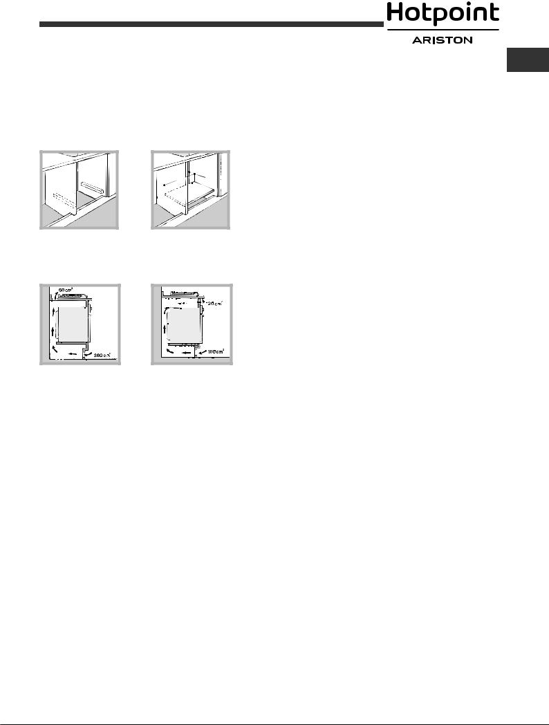
•Where the hob is not installed over a built-in oven, a wooden panel must be installed as insulation. This must be placed at a minimum distance of 20 mm from the lower part of the hob.
Ventilation
To ensure adequate ventilation, the back panel of the cabinet must be removed. It is advisable to install the oven so that it rests on two strips of wood, or on a completely flat surface with an opening of at least 45 x 560 mm (see diagrams).
. |
45 |
mm. |
mm |
|
|
560 |
|
|
Where a hob is installed above an oven without a forced ventilation cooling system, adequate ventilation must be provided inside the cabinet by means ofairholesthroughwhichaircanpass(seefigure).
Electrical connection
Hobs equipped with a three-pole power supply cable are designed to operate with alternating current at the voltage and frequency indicated on the data plate (this is located on the lower part of the appliance). The earth wire in the cable has a green and yellow cover. If the appliance is to be installed above a built-in electric oven, the electrical connection of the hob and the oven must be carried out separately, both for electrical safety purposes and to make extracting the oven easier.
Connecting the supply cable to the mains
Install a standardised plug corresponding to the load indicated on the data plate.
The appliance must be directly connected to the mains using an omnipolar circuit-breaker with a minimum contact opening of 3 mm installed between the appliance and the mains.
The circuit-breaker must be suitable for the charge indicated and must comply with current electrical regulations (the earthing wire must not be interrupted by the circuit-breaker). The supply cable must not come into contact with surfaces with temperatures higher than 50°C.
! The installer must ensure that the correct electrical connection has been made and that it is compliant with safety regulations.
Before connecting to the power supply, make sure that:
•the appliance is earthed and the plug is compliant with the law.
•the socket can withstand the maximum power of the appliance, which is indicated on the data plate.
•the voltage is in the range between the values indicated on the data plate.
•the socket is compatible with the plug of the appliance. If the socket is incompatible with the plug, ask an authorised technician to replace it. Do not use extension cords or multiple sockets.
! Once the appliance has been installed, the power supply cable and the |
GB |
electrical socket must be easily accessible. |
!The cable must not be bent or compressed.
!The cable must be checked regularly and replaced by authorised technicians only (see Assistance).
!The manufacturer declines any liability should these safety measures not be observed.
Gas connection
The appliance should be connected to the main gas supply or to a gas cylinder in compliance with current national regulations. Before carrying out the connection, make sure the cooker is compatible with the gas supply you wish to use. If this is not the case, follow the instructions indicated in the paragraph “Adapting to different types of gas”.
When using liquid gas from a cylinder, install a pressure regulator which complies with current national regulations.
! Check that the pressure of the gas supply is consistent with the values indicatedinTable1(“Burnerandnozzlespecifications”).Thiswillensurethe safe operation and longevity of your appliance while maintaining efficient energy consumption.
Attention!: Before connection remove a transport plug from the connecting hole of the cooker gas pipeline.
Connection with a rigid pipe (copper or steel)
! Connection to the gas system must be carried out in such a way as not to place any strain of any kind on the appliance.
There is an adjustable L-shaped pipe fitting on the appliance supply ramp and this is fitted with a seal in order to prevent leaks.The seal must always bereplacedafterrotatingthepipefitting(sealprovidedwithappliance).The gassupplypipefittingisathreaded1/2gascylindricalmaleattachment.
Connecting a flexible jointless stainless steel pipe to a threaded attachment
Thegassupplypipefittingisathreaded1/2gascylindricalmaleattachment.
These pipes must be installed so that they are never longer than 2000 mm when fully extended. Once connection has been carried out, make sure that theflexiblemetalpipedoesnottouchanymovingpartsandisnotcompressed.
! Only use pipes and seals that comply with current national regulations.
Checking the tightness of the connection
! When the installation process is complete, check the pipe fittings for leaks usingasoapysolution.Neveruseaflame.
Adapting to different types of gas
To adapt the hob to a different type of gas other than default type (indicated on the rating plate at the base of the hob or on the packaging), the burner nozzles should be replaced as follows:
1.Remove the hob grids and slide the burners off their seats.
2.Unscrew the nozzles using a 7 mm socket spanner, and replace them with nozzles for the new type of gas (see table 1 “Burner and nozzle characteristics”).
3.Reassemblethepartsfollowingtheaboveprocedureinthereverseorder.
4.Once this procedure is finished, replace the old rating sticker with one indicating the new type of gas used. Sticker are available from any of our Service Centres.
7
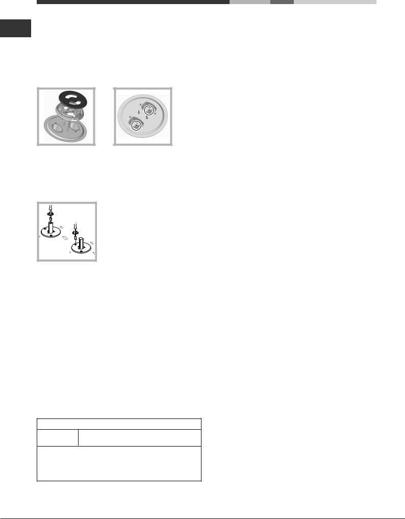
Replacing the Triple ring burner nozzles
GB 1. Remove the pan supports and lift the burners out of their housing. The burner consists of two separate parts (see pictures).
2.Unscrewthenozzlesusinga7mmsocketspanner.Replacethenozzles withmodelsthatareconfiguredforusewiththenewtypeofgas(seeTable
1). The two nozzles have the same hole diameter.
3.Replaceallthecomponentsbycompletingtheaboveoperationsinreverse order.
•Adjusting the burners’ primary air Does not require adjusting.
•Setting the burners to minimum
1. Turnthetaptothelowflameposition.
2. Removetheknobandadjusttheadjustment screw, which is positioned in or next to the tap pin,untiltheflameissmallbutsteady.
3.Havingadjustedtheflametotherequiredlowsetting,whiletheburneris alight, quickly change the position of the knob from minimum to maximum andviceversaseveraltimes,checkingthattheflamedoesnotgoout.
4.Someapplianceshaveasafetydevice(thermocouple)fitted.Ifthedevice fails to work when the burners are set to the low flame setting, increase thislowflamesettingusingtheadjustingscrew.
5.Once the adjustment has been made, replace the seals on the by-passes using sealing wax or a similar substance.
!If the appliance is connected to liquid gas, the regulation screw must be fastened as tightly as possible.
!Once this procedure is finished, replace the old rating sticker with one indicating the new type of gas used. Stickers are available from any of our Service Centres.
!Should the gas pressure used be different (or vary slightly) from the recommended pressure, a suitable pressure regulator must be fitted to the inlet pipe (in order to comply with current national regulations).
DATA PLATE
Electrical |
see data plate |
connections |
ECODESIGN
This appliance conforms to the EU Regulation no. 66/2014 implementing Directive 2009/125/EC.
standard EN 30-2-1
8
 Loading...