

Page 1
TM
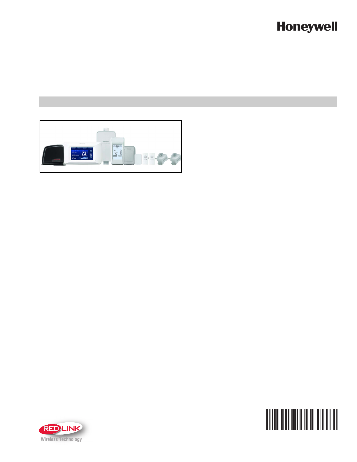
THX9321 Prestige® 2.0 and
THX9421 Prestige® IAQ 2.0
with EIM
• Delta T Alerts and Diagnostics
Alerts give customers a sense of security while also
enabling you to service or replace the equipment prior to a
loss of heating or cooling. Based on limits you set at installation, customers can be alerted when their system is not
operating as expected. The system alert will instruct customers to contact you for assistance. Requires EIM.
• Delta T Installer Test
Save time by viewing Delta T while running a system test to
verify proper operation. Requires EIM.
APPLICATION
The Prestige 2.0 and Prestige IAQ 2.0 Systems feature an
effortless, 7-Day programmable color touchscreen thermostat
that provides control of temperature, humidification,
dehumidification, and ventilation for up to 4 Heat/2 Cool heat
pump systems or up to 3 Heat/2 Cool conventional systems
for residential and commercial applications.
FEATURES
• RedLINK™ Compatible
Increase your content and profit per job by including
RedLINK™ accessories that meet your customers comfort
and convenience needs. RedLINK accessories include the
Wireless Outdoor Sensor, Portable Comfort Control (PCC),
Equipment Interface Module (EIM), RedLINK Internet
Gateway, Wireless Indoor Sensor, TrueSTEAM™ humidifier with Wireless Adapter, TrueZONE™ zoning panel with
Wireless Adapter, Vent Boost Remote and Entry/Exit
Remote.
• Customizable Service Reminders
Set up to 10 service reminders. Choose from the pre-set
options or customize your own. Reminders based on date,
outdoor temperature or a dry contact input will alert customers with instructions to contact you for assistance.
• Universal Inputs – S1 and S2
Assignable inputs allow you to configure Indoor and
Outdoor Temperature Sensors, Discharge and Return Air
Sensors or Dry Contact Devices. Dry Contact Devices can
be used to trip pre-set or customized alerts on the thermostat home screen. Requires EIM.
• User Interaction Log
The interaction log stores history of thermostat setting
changes including temperature, system and installer setup.
You can use the interaction log to save time by determining
if the issue is a system error or an accidental user error.
• Configurable for Residential and Light Commercial
Applications
One thermostat does it all to meet the needs of Residential
and Light Commercial applications. Simply select Residential or Commercial during the installer setup. If Commercial
is selected, the thermostat will use commercial language,
meet building codes and offer 365 day holiday scheduling.
• USB Port for Quick Installer Setup
Save time by using a USB stick to upload installer settings
and service reminders in one simple step.
• Selectable Sensors
When paired with a Wireless Indoor Sensor(s) you have
the ability to choose which sensor(s) to use for temperature, humidification and dehumidification. They can be
used in combination for temperature averaging—or individually—to condition humidity levels in separate spaces.
PRODUCT DATA
68-0311-01
Page 2

THX9321 PRESTIGE® 2.0 AND THX9421 PRESTIGE® IAQ 2.0 WITH EIM
CONTENTS
Application ........................................... 1
Specifications ...................................... 3
Ordering Information ........................... 2
System Installation .............................. 6
When Installing this Product... ..................... 6
Installing Equipment Interface Module (if used) 6
Wiring 24 Vac Common ................................ 6
Discharge and Return Air Temperature Sensor
Mounting Locations ...................................... 6
Discharge and Return Air Temperature Sensor Mounting
Locations ............................................................. 6
Return Air Temperature Sensor Mounting Location 7
Selecting Thermostat Location .................... 8
Installing Wallplate ........................................ 8
Install Optional Accessories .............. 9
Power Optional RedLINK™ Accessories .... 9
Link thermostat to EIM or TrueZONE® Wireless
Adapter ........................................................... 10
Link Optional RedLINK™ Accessories ....... 11
Mount Optional Accessories ........................ 13
Alerts and Diagnostics ....................... 50
Delta T Diagnostics ....................................... 50
Before You Set Up Delta T Diagnostics ....... 51
Setting up Alerts and Diagnostics ............... 51
Delta T Alerts ................................................. 54
Delta T Alerts and Utility Saver Switches ... 54
Data Logs ....................................................... 55
Alerts Log ............................................................. 55
User Interactions Log ........................................... 56
Dry Contact Alerts ........................................ 57
Installer Setup ...................................... 14
Set Date and Time ......................................... 49
Fan settings ................................................... 50
System Settings ............................................ 50
Installer Tests ...................................... 48
How to Use the Equipment Test .................. 48
How to Use the Wireless Signal Strength Test 49
Indoor Air Quality (IAQ) Control ......... 64
Humidification ............................................... 64
Set up Humidification ........................................... 64
Control Humidification Level ................................. 66
Dehumidification - Residential ..................... 66
Set up Dehumidification With Cooling System ..... 67
Set up Dehumidification With Whole House Dehumidifier
68
Set up Dehumidification Away Mode .................... 69
Control Dehumidification Level ............................. 70
Dehumidification - Commercial ................... 70
Set up Dehumidification With Cooling System ..... 71
Set up Dehumidification With Dehumidifier .......... 72
Control Dehumidification Level ............................. 74
Ventilation ...................................................... 74
Set up Ventilation ................................................. 75
IAQ Reminders ..................................... 78
Customizable Reminders ................... 79
USB Port ............................................... 81
Operation ............................................. 82
Residential Operation ................................... 84
Program Schedules .............................................. 84
To adjust program schedules ............................... 84
Program Schedule Override ................................. 85
Utility Scheduling .................................................. 86
System Status Information ................................... 82
Vacation Scheduling ............................................. 85
Commercial Operation .................................. 87
Program Schedules .............................................. 87
Program Schedule Override ................................. 87
Program Override Modes ............................. 88
Holiday/Event Scheduling ..................................... 88
Holiday Override ................................................... 88
Initiate Occupancy mode ...................................... 89
Menu: Preferences ........................................ 82
Menu: Temporary Schedule Changes ......... 85
Menu: Clean Screen ...................................... 82
Menu: Security Settings ............................... 83
Menu: Dealer Information ............................. 83
Advanced Features ....................................... 84
Adaptive Intelligent Recovery (residential use only) 84
Compressor Protection ......................................... 84
Heat Pump and Backup Heat Operation 62
Portable Comfort Control ................... 95
Remote Indoor Sensors ...................... 96
Commercial Features .......................... 87
ORDERING INFORMATION
When purchasing replacement and modernization products from your TRADELINE® wholesaler or distributor, refer to the
TRADELINE® Catalog or price sheets for complete ordering number. If you have additional questions, need further information,
or would like to comment on our products or services, please write or phone:
1. Your local Honeywell Environmental and Combustion Controls Sales Office (check white pages of your phone directory).
2. Honeywell Customer Care
1885 Douglas Drive North
Minneapolis, Minnesota 55422-4386
3. http://customer.honeywell.com or http://customer.honeywell.ca
International Sales and Service Offices in all principal cities of the world. Manufacturing in Belgium, Canada, China, Czech
Republic, Germany, Hungary, Italy, Mexico, Netherlands, United Kingdom, and United States.
68-0311—01 2
Page 3
THX9321 PRESTIGE® 2.0 AND THX9421 PRESTIGE® IAQ 2.0 WITH EIM
Ramp Rates .................................................... 89
Custom Names .............................................. 90
Remote Setback ............................................. 90
Economizer and Time of Day (TOD) Operation 91
Pre-Occupancy Purge ................................... 92
Staging Control .............................................. 59
Optional Accessories .......................... 94
Troubleshooting ................................... 124
Wiring ................................................... 102
EIM Wiring Diagrams ..................................... 104
Geothermal Radiant Heat .............................. 62
THX9321 Thermostat Wiring Diagrams ....... 107
THX9321 Thermostat Wiring Diagrams Using Universal Relays to Control Heating or Cooling 108
Wiring guide — IAQ Equipment (EIM or Thermo-
stat) ................................................................. 115
Economizer Module Wiring Diagrams ......... 116
Wiring C7089U1006 Outdoor Sensor ........... 118
Wiring guide — Wired Indoor Sensors ........ 119
Regulatory Information ....................... 124
SPECIFICATIONS
Accessories and Replacement Parts:
Item Part Number
Prestige 2.0 Thermostat THX9321R5030
Prestige IAQ 2.0 Thermostat THX9421R5013
Equipment Interface Module THM5421R1013
Wireless Adapter for TrueSTEAM and
Tr ue ZO N E
RedLINK Internet Gateway THM6000R1002
Portable Comfort Control REM5000R1001
Entry / Exit Remote REM1000R1003
Vent Boost Remote HVC20A1000
Occupancy Sensor for Remote Setback WSK-24
Wireless Outdoor Sensor C7089R1013
Wireless Indoor Sensor C7189R1004
Wired Outdoor Sensor (10K ohm NTC Negative Temperature Coefficient)
Wired Wall Mount Indoor Sensor (10K
ohm NTC - Negative Temperature
Coefficient)
Wired Wall Mount Indoor Sensor (20K
ohm NTC - Negative Temperature
Coefficient)
Wired Wall Mount Indoor Sensor (10K
ohm NTC - Negative Temperature
Coefficient)
Wired Flush Mount Indoor Sensor (20K
ohm NTC - Negative Temperature
Coefficient)
Wired Flush Mount Indoor Sensor (20K
ohm NTC - Negative Temperature
Coefficient)
Discharge or Return Air Sensor (10K ohm
NTC - Negative Temperature Coefficient)
Discharge or Return Air Sensor (20K ohm
NTC - Negative Temperature Coefficient)
Discharge or Return Air Sensor (20K ohm
NTC - Negative Temperature Coefficient)
Cover Plate (covers marks left by old
thermostats)
Battery Pack (for demo use only) THP1000A1007
Wire Saver Module THP9045A1023
* Prestige IAQ 2.0 Kits are packaged with 50062329-001 Dis-
charge and Return Air Sensors. Replacement Discharge/
Return Air Sensor part number is C7735A1000.
THM4000R1000
C7089U1006
C7189U1005
TR21
TR21-A
C7772A1004
C7772A1012
C7735A1000*
C7041
C7770A1006
50028399-001
3 68-0311—01
Page 4
THX9321 PRESTIGE® 2.0 AND THX9421 PRESTIGE® IAQ 2.0 WITH EIM
Thermostat Description:
Feature Description
Powering method • Common wire only
System types (up to
4 heat/2 cool heat
pump and up to 3
heat/2 cool
conventional)
• Gas, oil or electric heat with air
conditioning
• Warm air, hot water, high-efficiency
furnaces, heat pumps, steam and
gravity
• Cool only
Changeover Manual or Auto changeover selectable
System setting Em Heat-Heat-Off-Cool-Auto
Fan setting Auto-On-Circ-Follow Schedule
Electrical Ratings:
Volt ag e
Ter minal
(50/60 Hz)
W - O/B 18 to 30 VAC and
Max. Current
Rating
1.00A
750 mVDC
Y (cooling) 18 to 30 VAC 1.00A
G (fan) 18 to 30 VAC 0.50A
W2 - Aux 1 (heating) 18 to 30 VAC 0.60A
Y2 (cooling) 18 to 30 VAC 0.60A
W3 - Aux 2 18 to 30 VAC 1.00A
A-L/A (Output) 18 to 30 VAC 1.00A
U1, U1 18 to 30 VAC 0.50A
U2, U2 18 to 30 VAC 0.50A
U3, U3 18 to 30 VAC 0.50A
Power Consumption of THX9421/THX9321:
Full brightness = 3.0 VA
1/2 brightness = 2.1 VA
Backlight off = 1.9 VA
Operating Ambient Temperature:
THX9421/THX9321: 32 to 120 °F (0 to 48.9 °C)
THM5421R1013: -40 to 165 °F (-40 to 73.9 °C)
THM6000R1002: 32 to 120 °F (0 to 48.9 °C)
REM5000R1001: 32 to 120 °F (0 to 48.9 °C)
REM1000R1003: 32 to 120 °F (0 to 48.9 °C)
HVC20A1000: 32 to 120 °F (0 to 48.9 °C)
C7089R1013: -40 to 140 °F (-40 to 60 °C)
C7089U1006: -40 to 120 °F (-40 to 48.9 °C)
C7189R1004: 0 to 120 °F (-17.8 to 48.9 °C)
— For Optimal Battery Life: 35 to 114 °F (1.7 to 45.6 °C)
C7189U1005: 45 to 88 °F (7 to 32 °C)
C7772A1004: 45 to 99 °F (7 to 37 °C)
C7772A1012: 45 to 99 °F (7 to 37 °C)
TR21: 45 to 99 °F (7 to 37 °C)
TR21-A: 45 to 99 °F (7 to 37 °C)
C7735A1000: 0 to 200 °F (-17.8 to 93.3 °C)
C7041:
C7770A1006: 45 to 99 °F (7 to 37 °C)
THP1000A1007: 0 to 130 °F (-17.8 to 54.4 °C)
THP9045A1023: -40 to 163 °F (-40 to 73 °C)
Shipping Temperature:
THX9421/THX9321: -20 to 120 °F (-28.9 to 48.9 °C)
THM5421R1013: -20 to 165 °F (-28.9 to 73.9 °C)
THM6000R1002: -20 to 120 °F (-28.9 to 48.9 °C)
REM5000R1001: -20 to 120 °F (-28.9 to 48.9 °C)
REM1000R1003: -20 to 120 °F (-28.9 to 48.9 °C)
HVC20A1000: -20 to 120 °F (-28.9 to 48.9 °C)
C7089R1013: -40 to 120 °F (-40 to 48.9 °C)
C7089U1006: -40 to 130 °F (-40 to 54.4 °C)
C7189R1004: -20 to 120 °F (-28.9 to 48.9 °C)
C7189U1005: -20 to 120 °F (-28.9 to 48.9 °C)
C7772A1004: -40 to 150 °F (-40 to 65.5 °C)
C7772A1012: -40 to 150 °F (-40 to 65.5 °C)
TR21: -40 to 150 °F (-40 to 65.5 °C)
TR21-A: -40 to 150 °F (-40 to 65.5 °C)
C7735A1000: -20 to 120 °F (-28.9 to 48.9 °C)
C7041:
C7770A1006: -40 to 150 °F (-40 to 65.5 °C)
THP1000A1007: 0 to 130 °F (-17.8 to 54.4 °C)
THP9045A1023: -40 to 185 °F (-40 to 85 °C)
Operating Relative Humidity:
THX9421/THX9321: 5 to 90% non-condensing
THM5421R1013: 5 to 95% non-condensing
THM6000R1002: 5 to 90% non-condensing
REM5000R1001: 5 to 90% non-condensing
REM1000R1003: 5 to 90% non-condensing
HVC20A1000: 5 to 90% non-condensing
C7089R1013: 0 to 100% condensing
C7089U1006: 5 to 95% non-condensing
C7189R1004: 5 to 90% non-condensing
C7189U1005: 5 to 95% non-condensing
C7772A1004: 5 to 95% non-condensing
C7772A1012: 5 to 95% non-condensing
TR21: 5 to 95% non-condensing
TR21-A: 5 to 95% non-condensing
C7770A1006: 5 to 95% non-condensing
THP1000A1007: 5 to 90% non-condensing
THP9045A1023: 5 to 90% non-condensing
Temperature Setting Range:
Heating: 40 to 90 °F (4.5 to 32 °C).
Cooling: 50 to 99 °F (10 to 37 °C).
Humidification Setting Range:
10% to 60% RH.
Dehumidification Setting Range:
40% to 80% RH.
Humidity Display Range:
0% to 99%.
Cool Indication:
Prestige 2.0 and Prestige IAQ 2.0 displays “Cool On” when the
thermostat turns the cooling on.
Heat Indication:
Prestige 2.0 and Prestige IAQ 2.0 displays “Heat On” when the
thermostat turns the heating on.
Auxiliary Heat Indication:
Prestige 2.0 and Prestige IAQ 2.0 displays “Auxiliary Heat On”
when the thermostat turns the auxiliary heat on.
Interstage Differential:
Comfort: The thermostat keeps the indoor temperature within 1
degree of the setpoint (droop less control). The thermostat
turns on stage 2 when the capacity on stage 1 reaches
90%.
When the interstage differential is set to 1.0 or higher, the ther-
mostat stages the equipment based on how far the indoor
temperature is from the setpoint (ISU 3030 to 3090). See
page 21 for more information.
68-0311—01 4
Page 5
THX9321 PRESTIGE® 2.0 AND THX9421 PRESTIGE® IAQ 2.0 WITH EIM
M33329
6-51/64 (173)
3-19/64 (84)
1-13/32
(36)
3-29/32
(99)
Clock Accuracy: ± 1 minute per month at 77 °F (25 °C). ± 2
minutes per month over the operating ambient temperature
range.
Color/Finish:
THX9421/THX9321: Arctic White
THM5421R1013: Gray
THM6000R1002: Black
REM5000R1001: Arctic White / Gray
REM1000R1003: Arctic White
HVC20A1000: Arctic White
C7089R1013: Gray
C7189R1004: Arctic White
C7189U1005: Premier White
C7772A1004: Brushed Stainless Steel
C7772A1012: Brushed Stainless Steel
TR21: White
TR21-A: White
C7735A1000: Gray
50028399-001: Arctic White
THP1000A1007: Gray
THP9045A1023: Gray
Mounting Means:
Thermostat mounts directly on the wall in the living space
using mounting screws and anchors provided. Fits a horizontal 2 x 4 in. junction box.
Equipment Interface Module (EIM) mounts on HVAC equip-
ment or on a wall in the equipment room.
C7735A1000: Probe: 3-3/4 x 1/4 inches
(77 x 6.4 mm)
C7735A1000: Cap Diameter: 2-7/16 inches
(62 mm)
C7041: 4-3/16 x 2-5/16 x 1-11/16 inches
(107 x 59 x 43 mm)
C7770A1006: Probe: 6 x 1/4 inches
(152 mm x 6.4 mm)
50028399-001: 5-1/2 x 7-7/8
(141 x 201 mm)
THP1000A1007: 6-1/2 x 3-11/16 x 1-1/8 inches
(165 x 93.5 x 29 mm)
THP9045A1023: 2-7/8 x 3-3/8 x 15/16 inches
(73 x 86 x 23 mm)
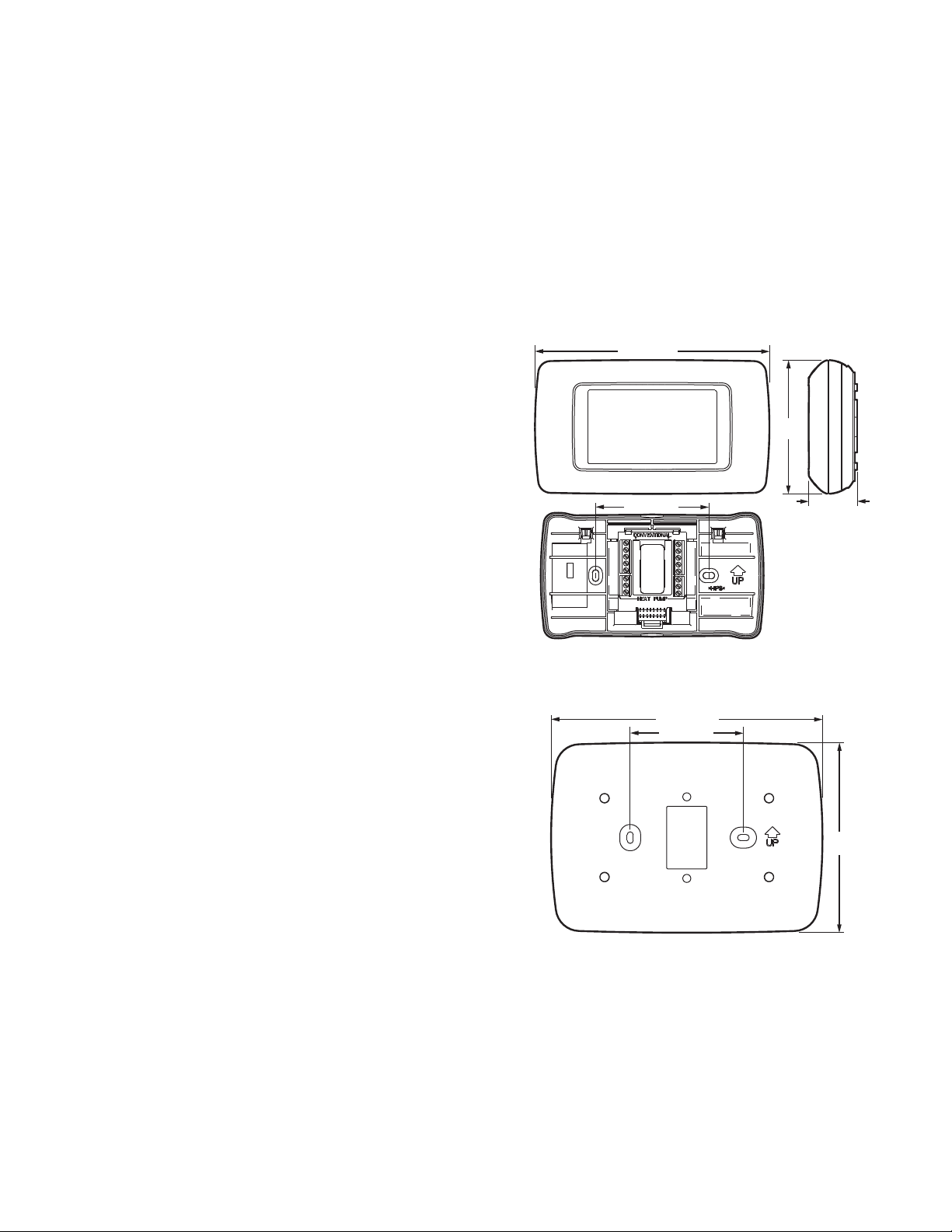
Dimensions:
THX9421 / THX9321: 3-7/8 x 6-13/16 x 1-7/16 inches
(99 x 173 x 36 mm)
THM5421R1013: 9-5/16 x 4-13/16 x 1-19/32 inches
(237 x 122 x 40.5 mm)
THM6000R1002: 6 x 4-7/8 x 2-1/2 inches
(152 x 124 x 64 mm)
REM5000R1001: 6-1/4 x 3-1/8 x 1-5/8 inches
(158 x 80 x 38 mm)
REM1000R1003: 3-15/16 x 1-15/16 x 5/8 inches
(101 x 50 x 16 mm)
HVC20A1000: 3-15/16 x 1-15/16 x 5/8 inches
(101 x 50 x 16 mm)
C7089R1013: 5 x 3-1/2 x 1-11/16 inches
(127 x 89 x 43 mm)
C7089U1006 (mounting clip): 1-1/2 inches
(38 mm)
C7189R1004: 2-7/8 x 1-7/8 x 15/16 inches
(74 x 48 x24 mm)
C7189U1005: 2-9/32 x 1-1/2 x 11/16 inches
(58 x 38 x 18 mm)
C7772A1004: 4-1/2 x 2-3/4 x 5/16 inches
(114 x 70 x 8 mm)
C7772A1012: 4-1/2 x 2-3/4 x 5/16 inches
(114 x 70 x 8 mm)
TR21:4-9/16 x 3 x 7/8 inches
(116 x 76.5 x 22 mm)
TR21-A: 4-9/16 x 3 x 7/8 inches
(116 x 76.5 x 22 mm)
Fig. 1. Dimensions of thermostat in in. (mm).
7-29/32 (201)
3-19/64 (84)
5-1/2
(140)
M33330
Fig. 2. Dimensions of Prestige cover plate in in. (mm).
5 68-0311—01
Page 6
THX9321 PRESTIGE® 2.0 AND THX9421 PRESTIGE® IAQ 2.0 WITH EIM
CAUTION
MCR32388
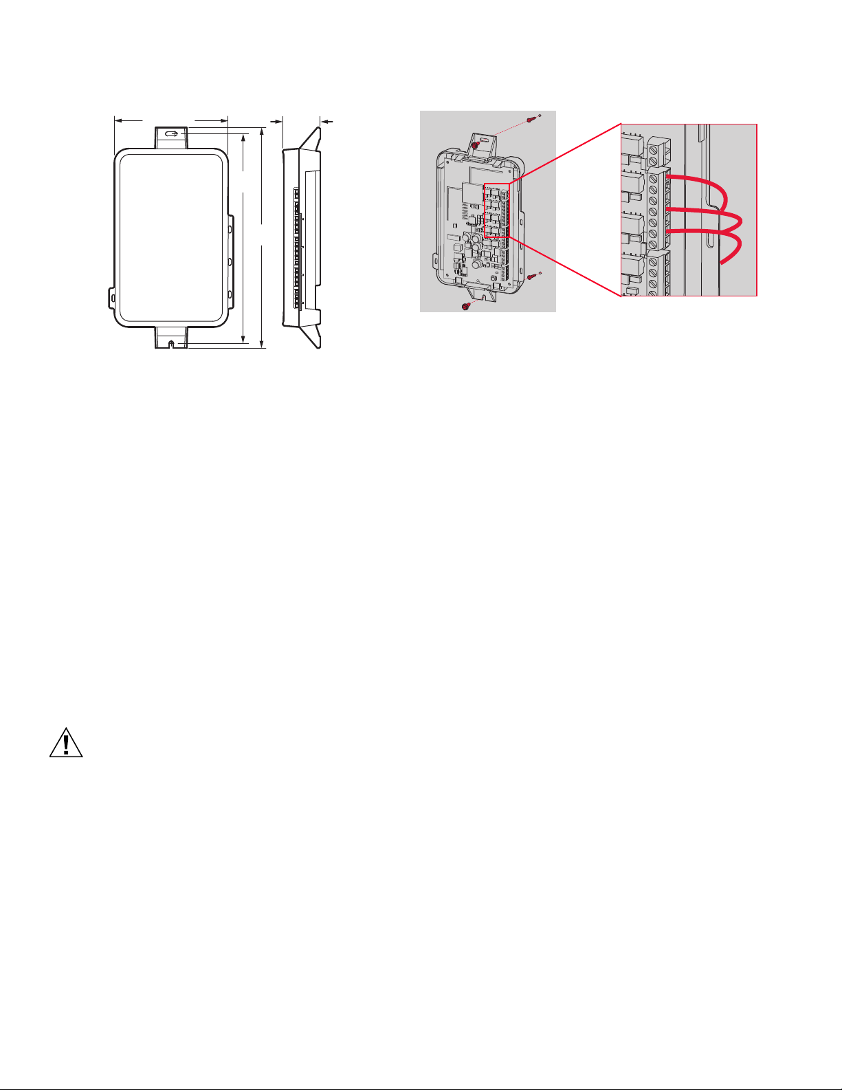
9-11/32
(237)
1-19/32
(41)
M33331
4-53/64 (123)
8-7/8
(225)
Fig. 3. Dimensions of Equipment Interface Module in in.
(mm).
SYSTEM INSTALLATION
When Installing this Product...
1. Read these instructions carefully. Failure to follow the
instructions can damage the product or cause a hazardous condition.
2. Check the ratings given in the instructions to make sure
the product is suitable for your application.
3. Installer must be a trained, experienced service
technician.
4. After completing installation, use these instructions to
verify the product operation.
Installing Equipment Interface Module (if used)
If no Equipment Interface Module is used, skip to “Selecting
Thermostat Location” beginning on page 8.
Electrical Hazard.
Can cause electrical shock or equipment damage.
Disconnect power before wiring.
The Equipment Interface Module (EIM) can be mounted
vertically on the HVAC equipment or on a wall in the equipment
room.
1. Use screws & anchors as appropriate for the mounting
surface. Mount the EIM near the HVAC equipment, or on
the equipment itself.
2. To wire the EIM, strip 1/4” insulation, then insert wires
(see Fig. 4). For wiring diagrams, see “Wiring” beginning
on page 102.
R
C
W
O/B
W2
AUX1
W3
AUX2
Y
Y2
G
L
MCR32389
Fig. 4.
Wiring 24 Vac Common
• Single-Transformer System—Connect the common side of
the transformer to the C screw terminal of the EIM. Leave
the metal jumper wires in place between R, Rc, and RH.
• Two-Transformer System—Connect the common side of the
cooling transformer to the C screw terminal of the EIM.
Remove the metal jumper wire between Rc and Rh.
Connect the hot side of heating transformer to Rh and leave
the jumper wire between R and Rc and connect the hot side
of cooling transformer to R or Rc.
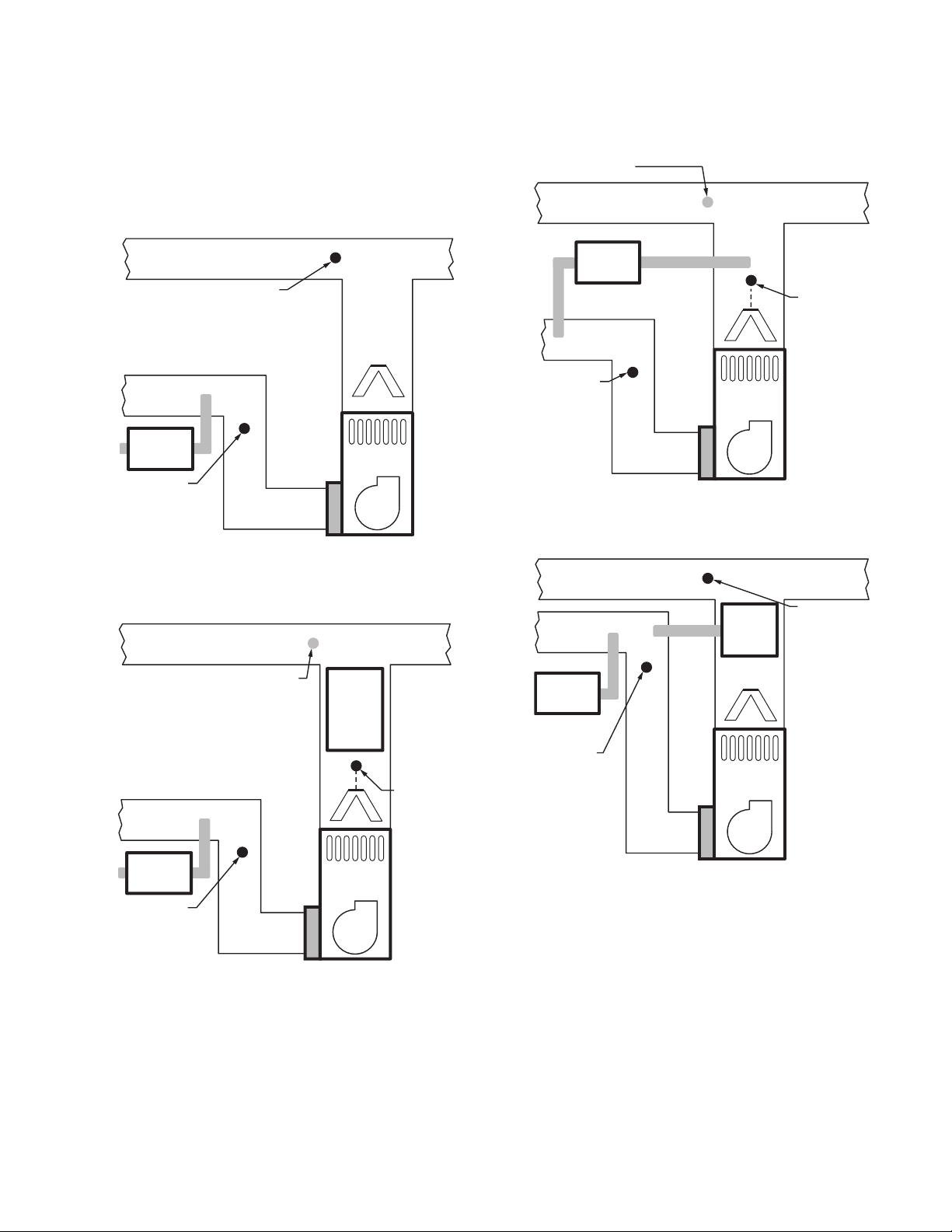
Discharge and Return Air Temperature Sensor Mounting Locations
Refer to the guidelines below and Fig. 5–9 for mounting
locations of the Discharge and Return Air Temperature
Sensors.
Discharge Air Temperature Sensor
Mounting Location
1. Mount the Discharge Air Temperature Sensor on the
supply duct in a location where the air is mixed well.
Mount the Discharge Air Temperature Sensor out of sight
of the A-Coil/Heat Exchanger when possible. See Fig. 5.
2. When possible, mount the Discharge Air Temperature
Sensor upstream of a Steam Humidifier, a Fan Powered
Humidifier or a Dehumidifier that is ducted to the supply.
See Fig. 6–7.
3. If space does not allow a Discharge Air Temperature
Sensor upstream of a Steam Humidifier or Fan Powered
Humidifier, mount the Discharge Air Temperature Sensor
downstream of the Humidifier. See Fig. 6. When setting
the Delta T Limits (see “Set Delta T Limits” on page 53),
be sure to consider the affect that the humidifier has on
Delta T.
4. If a Bypass Humidifier is installed, mount the Discharge
Air Temperature Sensor downstream of the Bypass
Humidifier. See Fig. 8–9.
68-0311—01 6
Page 7
THX9321 PRESTIGE® 2.0 AND THX9421 PRESTIGE® IAQ 2.0 WITH EIM
MOUNT DISCHARGE
SENSOR HERE
M33074
HEAT
EXCHANGER
BLOWER
VENTILATOR
OR
DEHUMIDIF IER
MOUNT RETURN
SENSOR HERE
DOWNSTREAM OF
VENTILATOR OR
DEHUMIDIFIER
A-COIL
MOUNT RETURN
SENSOR HERE
MOUNT DOWNSTREAM
OF BYPASS HUMIDIFIER,
DEHUMIDIFIER OR
VENTILATOR
HEAT
EXCHANGER
BLOWER
VENTILATOR
OR
DEHUMIDIF IER
MOUNT
DISCHARGE
SENSOR HERE
MOUNT
DOWNSTREAM
OF BYPASS
HUMIDIFIER
BYPASS
HUMIDIFIER
M33078A
Return Air Temperature Sensor Mounting Location
1. Install the Return Air Temperature Sensor on the return
duct in a location where the air is mixed well. Mount the
Return Air Temperature Sensor downstream of a Bypass
Humidifier, Dehumidifier or Ventilator. See Fig. 5–9.
ALTERNATE MOUNTING LOCATION FOR DISCHARGE
SENSOR. WHEN SETTING THE LIMITS, BE SURE
TO CONSIDER THE AFFECT THAT THE DEHUMIDIFIER
HAS ON DELTA T.
DEHUMIDIF IER
MOUNT RETURN
SENSOR HERE
DOWNSTREAM OF
DEHUMIDIFIER
HEAT
EXCHANGER
BLOWER
MOUNT
DISCHARGE
SENSOR HERE
ABOVE CENTER
OF A-COIL
UPSTREAM OF
DEHUMIDIFIER
M33076A
ALTERNATE MOUNTING LOCATION FOR DISCHARGE
SENSOR. WHEN SETTING THE LIMITS, BE SURE TO
CONSIDER THE AFFECT THAT THE HUMIDIFIER HAS
ON DELTA T.
VENTILATOR
OR
DEHUMIDIF IER
MOUNT RETURN
SENSOR HERE
DOWNSTREAM OF
VENTILATOR OR
DEHUMIDIFIER
Fig. 5.
Fig. 6.
STEAM OR
FAN
POWERED
HUMIDIFIER
HEAT
EXCHANGER
BLOWER
MOUNT
DISCHARGE
SENSOR HERE
ABOVE CENTER
OF A-COIL
UPSTREAM OF
STEAM OR FAN
POWERED
HUMIDIFIER
M33075A
Fig. 7.
Fig. 8.
7 68-0311—01
Page 8
THX9321 PRESTIGE® 2.0 AND THX9421 PRESTIGE® IAQ 2.0 WITH EIM
CAUTION
MOUNT RETURN
SENSOR HERE
MOUNT DOWNSTREAM
OF BYPASS HUMIDIFIER,
DEHUMIDIFIER OR
VENTILATOR
HEAT
EXCHANGER
BLOWER
VENTILATOR
OR
DEHUMIDIF IER
MOUNT
DISCHARGE
SENSOR HERE
BYPASS
HUMIDIFIER
M33079A
M32995
5 FEET
[1.5 METERS]
YES
NO
NO
NO
M19925
MCR29241
MCR32386
Do not install the thermostat where it can be affected by:
Fig. 9.
— Drafts or dead spots behind doors and in corners.
— Hot or cold air from ducts.
— Radiant heat from sun or appliances.
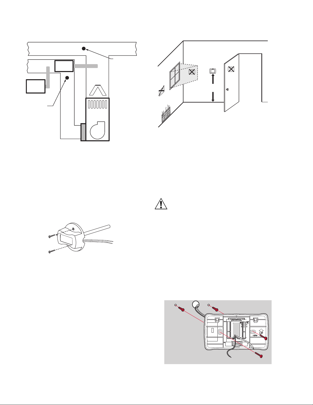
INSTALLATION
Use the following steps to mount the Discharge/Return Air
Sensors:
1. Attach plastic cover to the sensor probe.
— Concealed pipes and chimneys.
— Unheated (uncooled) areas such as an outside wall behind
the thermostat.
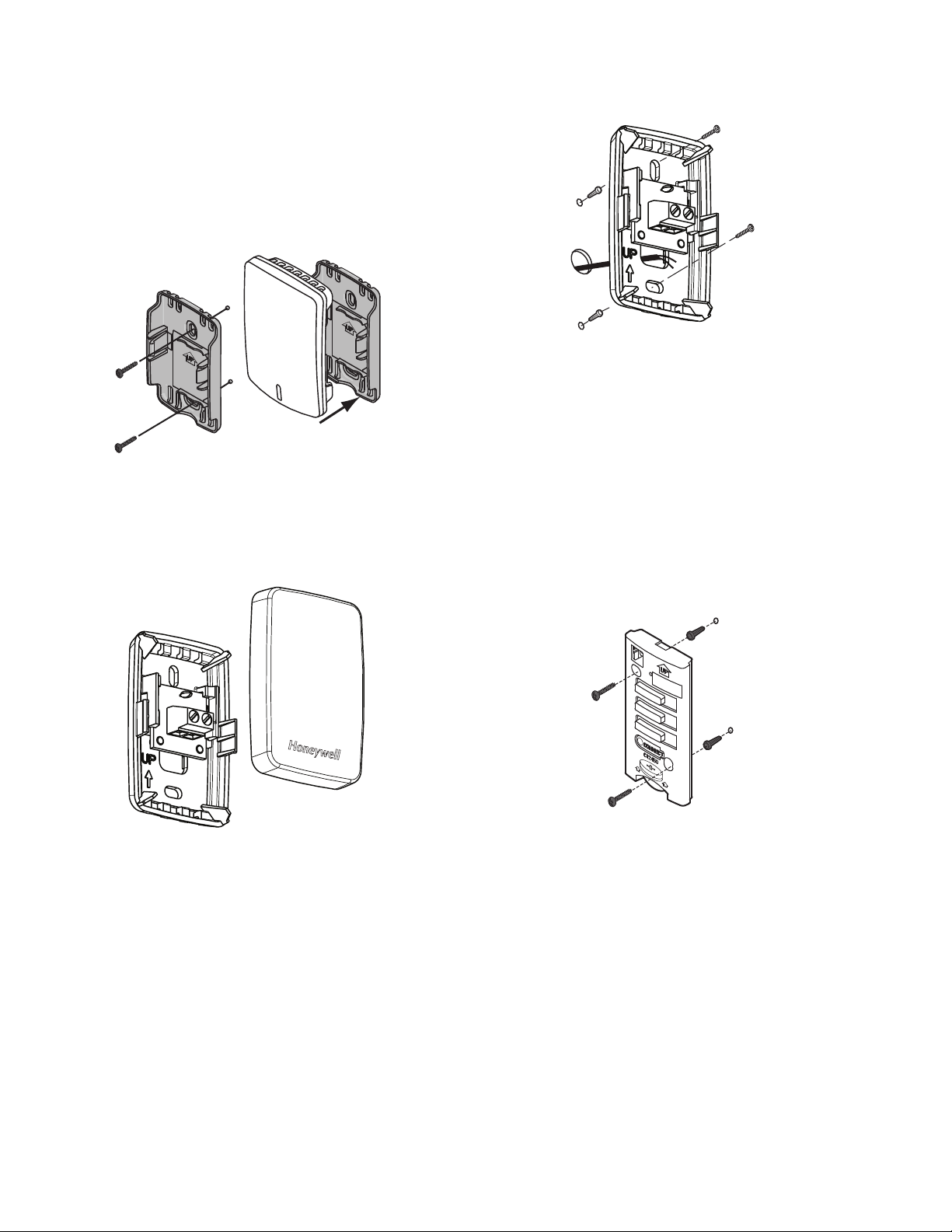
Installing Wallplate
2. Drill 1/4-inch hole for the sensor probe and mount it to
the ductwork with enclosed screws (see Fig. 10).
3. Connect wires to S1 or S2 terminals at the EIM.
4. Configure the S1 or S2 terminals in the Installer Setup at
the thermostat.
Fig. 11. Selecting thermostat location.
Electrical Hazard.
Can cause electrical shock or equipment damage.
Disconnect power before wiring.
Selecting Thermostat Location
Install the thermostat about 5 ft. (1.5m) above the floor in an area
with good air circulation at average temperature. See Fig. 11.
68-0311—01 8
Fig. 10. Mounting Discharge/Return Air Sensor.
The thermostat can be mounted horizontally on the wall or on a
4 in. x 2 in. (101.6 mm x 50.8 mm) wiring box.
1. Position and level the wallplate (for appearance only).
2. Use a pencil to mark the mounting holes.
3. Remove the wallplate from the wall and, if drywall, drill
two 3/16-in. holes in the wall, as marked. For firmer
material such as plaster, drill two 7/32-in. holes. Gently
tap anchors (provided) into the drilled holes until flush
with the wall.
4. Position the wallplate over the holes, pulling wires
through the wiring opening. See Fig. 12.
5. Insert the mounting screws into the holes and tighten.
Fig. 12. Mounting wallplate.
Page 9
THX9321 PRESTIGE® 2.0 AND THX9421 PRESTIGE® IAQ 2.0 WITH EIM
MCR32387
MCR32938
THX9421 Installation
INSTALLATION WITH EQUIPMENT INTERFACE MODULE
(EIM)
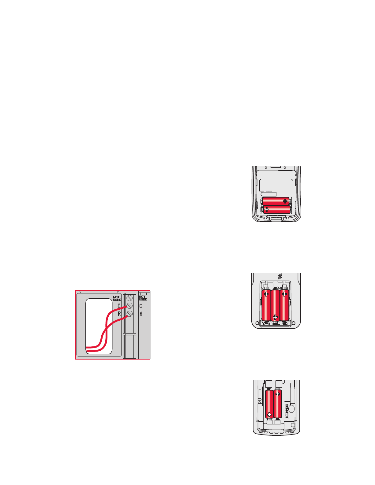
1. Wire to C and R terminals of the EIM or to a separate 24
volt transformer (not provided). See Fig. 13.
2. Snap thermostat onto wallplate after wiring is complete.
INSTALLATION WITH TRUEZONE WIRELESS ADAPTER
1. Wire to C and R terminals of the TrueZONE panel or to a
separate 24 volt transformer (not provided). See Fig. 13.
2. Snap thermostat onto wallplate after wiring is complete.
THX9321 Installation
THERMOSTAT WIRED DIRECTLY TO THE HVAC
EQUIPMENT OR ZONE PANEL
1. Refer to “THX9321 Thermostat Wiring Diagrams” begin-
ning on page 107.
2. Snap thermostat onto wallplate after wiring is complete.
INSTALLATION WITH EQUIPMENT INTERFACE MODULE
(EIM)
1. Wire to C and R terminals of the EIM or to a separate 24
volt transformer (not provided). See Fig. 13.
2. Snap thermostat onto wallplate after wiring is complete.
NOTE: Note: When the THX9321 thermostat is used with
an EIM, the relays in the thermostat do not function.
INSTALLATION WITH TRUEZONE WIRELESS ADAPTER
1. Wire to C and R terminals of the TrueZONE panel or to a
separate 24 volt transformer (not provided). See Fig. 13.
2. Snap thermostat onto wallplate after wiring is complete.
NOTE: When the THX9321 thermostat is used with a
TrueZONE Wireless Adapter, the relays in the
thermostat do not function.
INSTALL OPTIONAL ACCESSORIES
Power Optional RedLINK™ Accessories
1. If no wireless accessories are used, skip to “Link thermo-
stat to EIM or TrueZONE® Wireless Adapter” beginning
on page 10.
2. If no wireless accessories are used and there is no EIM
or TrueZONE Wireless Adapter, skip to “Installer Setup”
beginning on page 14.
3. Install batteries in the wireless accessories.
Outdoor air sensor
1. Install 2 fresh AA lithium batteries.
MCR32937
Fig. 14.
Portable Comfort Control
1. Install 3 fresh AA alkaline batteries.
Fig. 13. Inserting wires in thermostat terminal block.
MCR32939
Fig. 15.
Indoor air sensor
1. Install 2 fresh AAA alkaline batteries.
Fig. 16.
9 68-0311—01
Page 10
THX9321 PRESTIGE® 2.0 AND THX9421 PRESTIGE® IAQ 2.0 WITH EIM
M32940
THM4000R1000
TrueSTEAM
MCR31476
6
543
2
ON
OFF
1
MCR33269
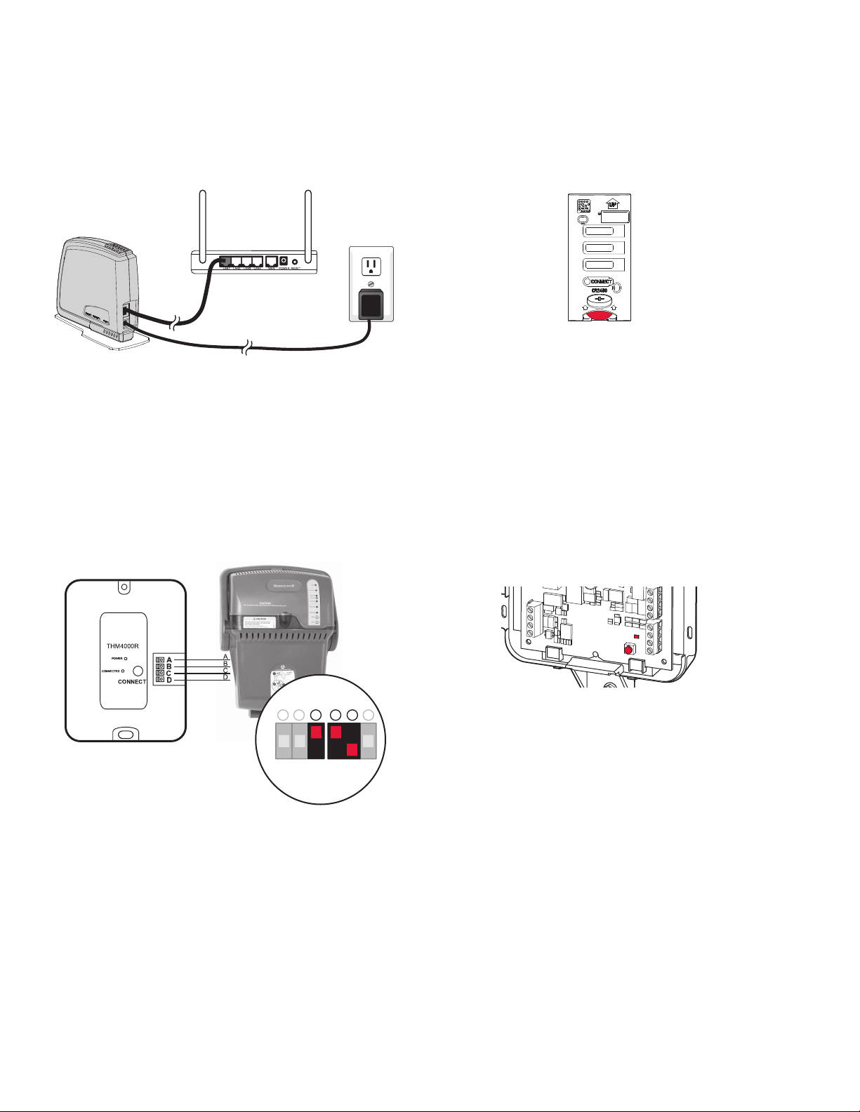
RedLINK™ Internet Gateway
1. Connect power cord to an electrical outlet not controlled
by a wall switch.
2. Connect ethernet cable to router and the RedLINK Internet Gateway.
Fig. 17.
TrueSTEAM
1. Wire and power TrueSTEAM.
2. Connect the ABCD terminals between TrueSTEAM and
the THM4000 Wireless Adapter.
3. Adjust the DIP Switches on TrueSTEAM as follows when
using the Wireless Adapter:
• DIP3: UP
• DIP4: UP
• DIP5: DOWN
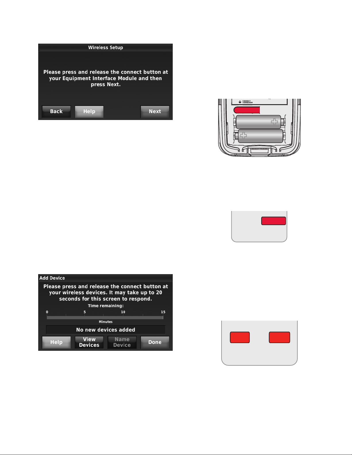
Entry/Exit Remote or Vent Boost Remote
1. Remove the cover.
2. Insert the CR2450 coin cell battery (included) into the
slot at the bottom of the remote. See polarity marking on
the remote.
Fig. 19. Installing Entry/Exit Remote or Vent Boost Remote
battery.
3. The LED will briefly flash green. If it flashes red, battery
is not good.
Link thermostat to EIM or TrueZONE® Wireless Adapter
If no EIM or TrueZONE® Wireless Adapter are used, skip to
“Link Optional RedLINK™ Accessories” beginning on page 11.
1. Press and release the CONNECT button at the EIM or
Wireless Adapter, and make sure the “Connected” light
is flashing green.
Fig. 18. Powering TrueSTEAM wireless adapter.
CONNECTED
CONNECT
S2
S2
S1
S1
MCR32941
Fig. 20. EIM CONNECT button.
2. If the “Connected” light does not flash, make sure no
other RedLINK devices are in Wireless Setup mode,
then try again.
NOTE: If the “Power” light at the Wireless Adapter does
not turn on, consult the TrueZONE manual for
help.
3. While the “Connected” light is flashing, follow the
prompts on the thermostat screen until you reach the
Wireless Setup screen.
4. Press NEXT to link the thermostat. After a brief delay, the
screen will display “Device Connected.”
68-0311—01 10
Page 11
THX9321 PRESTIGE® 2.0 AND THX9421 PRESTIGE® IAQ 2.0 WITH EIM
MCR28847A
NOYES
CONNECT MORE?
M28482
Fig. 21.
NOTE: If the thermostat did not connect to the EIM or
Wireless Adapter, verify the “Connected” LED is
still flashing and the thermostat is at least 2 feet
away from the EIM or Wireless Adapter, and
repeat steps 1–4 above.
press MENU > EQUIPMENT STATUS to find
the date code. Scroll down to WIRELESS
DEVICE MANAGER and then select ADD
DEVICE.
Link Wireless Outdoor Sensor
1. Press and release the CONNECT button. After a short
delay, the thermostat will display “Wireless Outdoor Sensor added” on the Add Device screen.
“Connected” Status Light (Fig. 20)
• Green flashing: In Wireless Setup mode.
• Green steady: RedLINK device(s) are communicating.
• Red: RedLINK device(s) not communicating. Check EIM
and RedLINK devices.
Link Optional RedLINK™ Accessories
NOTE: If you are not connecting any RedLINK devices,
skip to “Installer Setup” beginning on page 14.
1. While the Add Device screen (see Fig. 22) is displayed
on the thermostat, press and release the CONNECT button on each wireless device. Accessories need to be at
least 2 feet away from the thermostat, EIM, or TrueZONE
Wireless Adapter during the linking process.
Fig. 23. Wireless outdoor sensor connect button.
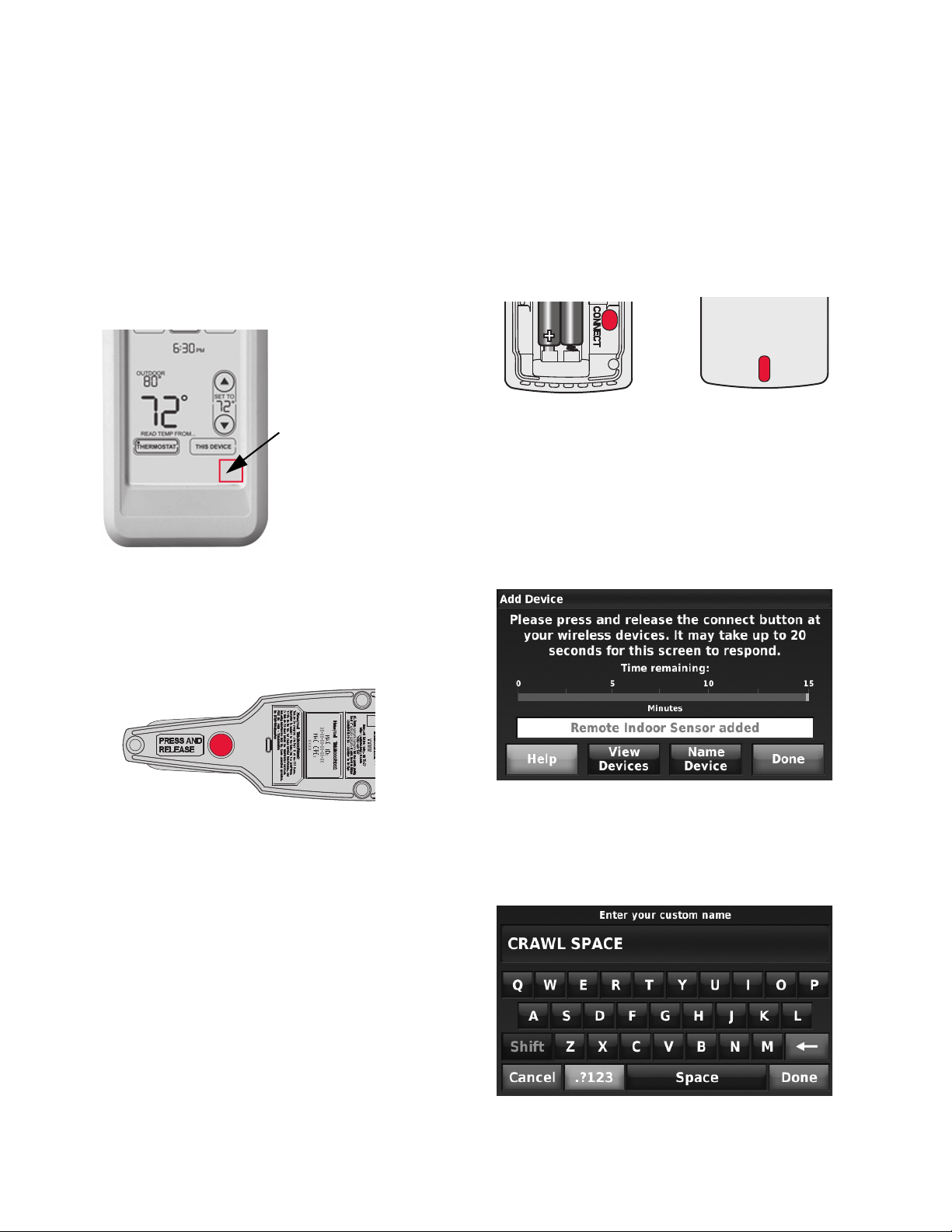
Link Portable Comfort Control
1. Press CONNECT on the Portable Comfort Control dis-
play screen.
CONNECT
WIRELESS SETUP
MCR32942
Fig. 24. Portable Comfort Control connect button.
2. Press DONE on the Portable Comfort Control when it
displays “Connected.”
3. Press “No” at the next screen to save and exit, or press
“Yes” if you need to connect additional thermostats to the
Portable Comfort Control. See Fig. 25.
NOTE: The Portable Comfort Control can control up to 16
thermostats.
2. Press DONE on the Add Device screen after ALL
devices have been linked (see Fig. 22).
NOTE: If you need to return to the “Add Device” screen
Fig. 22. Add Device screen.
to add devices later, press MENU and scroll
down to INSTALLER OPTIONS. Enter the date
code (password) when prompted. The date
code is printed on the back of the thermostat or
Fig. 25. Connect additional thermostats to Portable
Comfort Control.
4. Follow the same linking procedure as above to connect
additional thermostats.
11 68-0311—01
Page 12
THX9321 PRESTIGE® 2.0 AND THX9421 PRESTIGE® IAQ 2.0 WITH EIM
Press and hold
the blank space
(or arrow may be
present)
MCR32943
MCR32934
MCR32935
ERROR MESSAGES:
E1 29: Incompatible device cannot be connected.
E1 34: Low RF signal. Move device to a different location and
try again.
E1 38: Make sure the thermostat, EIM, or TrueZONE Wireless
Adapter is in Wireless Setup mode, and the Portable Comfort
Control is at least 2 feet away (600 mm).
NOTE: The linking procedure will time out if there is no
keypress for 30 minutes. To begin again, press
and hold in the lower right corner of the screen
until the display changes (about 3 seconds). See
Fig. 26.
Fig. 26. Restarting the linking process.
Link TrueSTEAM
1. Press and release the CONNECT button on THM4000
Wireless Adapter. After a short delay, the CONNECTED
status light will glow steady green.
Link Wireless Indoor Sensor
1. Press and release the CONNECT button. After a short
delay, the status light (see Fig. 25) will glow green for 15
seconds. If the status light turns red, the sensor did not
link with the thermostat.
Fig. 28. Wireless indoor sensor connect button and status
light.
NOTE: In normal operation, the status light remains off.
If it begins flashing red, batteries are low (power
will be depleted after 2–3 weeks).
2. If you are installing more than 1 wireless indoor sensor,
give each sensor a name as you install it. Press Name
Device, as shown in Fig. 29.
Link RedLINK Internet Gateway
1. Press and release the button on the bottom of the Inter-
net Gateway. After a short delay, the RedLINK status
light will glow steady green.
Fig. 27. RedLINK Internet Gateway connect button.
NOTE: The Internet Gateway must be registered online
before use at www.mytotalconnectcomfort.com.
Enter the MAC ID and MAC CRC numbers located
on the bottom of the Internet Gateway. For additional information, see instructions provided with
the device.
Fig. 29.
3. Type the sensor name and press Done. The sensor
names are used when selecting which sensor to use for
temperature, humidification, and dehumidification control.
68-0311—01 12
Fig. 30.
Page 13
THX9321 PRESTIGE® 2.0 AND THX9421 PRESTIGE® IAQ 2.0 WITH EIM
M28849A
M7514
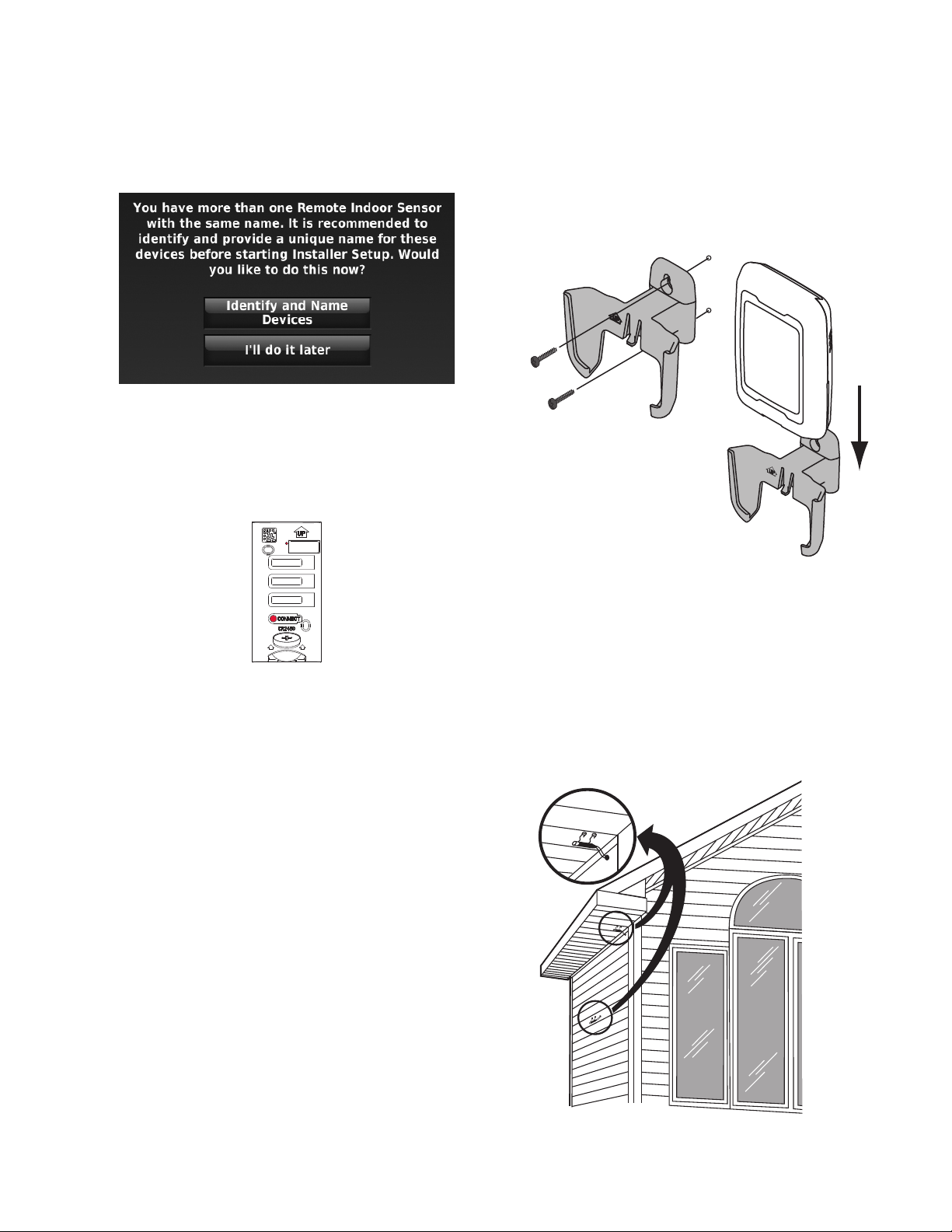
NOTE: If you link more than 1 wireless indoor sensor,
and forget to name them, you will be prompted
to name each wireless indoor sensor after you
exit wireless setup. See Fig. 31.
Fig. 31.
Link Entry/Exit Remote or Vent Boost
Remote
1. Press and release CONNECT button.
• where snow, ice or debris can cover it.
MOUNTING C7089R1013 WIRELESS OUTDOOR SENSOR
Use the following steps to mount the sensor (see Fig. 33):
1. Mount the sensor on a vertical exterior wall, at least 6
inches below any overhang. Choose a location protected
from direct sunlight.
2. Place sensor securely in bracket, facing away from wall.
M28491
MCR33096
Fig. 32. Connect button and status light on Entry/Exit
Remote or Vent Boost Remote.
2. After a short delay, the status light will glow green for 15
seconds. If the status light turns red, the remote did not
link with the thermostat for the connection process.
NOTE: The thermostat can work with up to 3 Entry/Exit
remotes. Each Entry/Exit remote can control up to
16 thermostats.
NOTE: The thermostat can work with up to 6 Vent Boost
remotes.
Mount Optional Accessories
Mounting Outdoor Sensor
Mount the sensor where:
• it cannot be tampered with.
• there is good air circulation.
• it can measure true outdoor ambient temperature and
humidity.
• wire distance between C7089U1006 and EIM is less than
200 feet (wired sensor only).
Fig. 33. Mounting Outdoor Sensor.
MOUNTING C7089U1006 WIRED OUTDOOR
TEMPERATURE SENSOR
Use the following steps to mount the sensor:
1. Remove the sensor from the mounting clip.
2. Mark the area on the location selected for mounting the
sensor mounting clip.
3. Mount the clip.
4. See “Wiring C7089U1006 Outdoor Sensor” on page 118.
Do not mount the sensor:
• in direct sunlight.
• where hot or cold air blows on the sensor. Discharge line
from an outdoor compressor unit, vent or fan causes
inaccurate temperature readings.
Fig. 34. Typical locations for C7089U1006 Outdoor Sensor.
13 68-0311—01
Page 14
THX9321 PRESTIGE® 2.0 AND THX9421 PRESTIGE® IAQ 2.0 WITH EIM
M32936
M24056
M33095
Mounting C7189R1004 Wireless Indoor
Sensor
Use the following steps to mount the sensor (see Fig. 35):
1. Remove the wallplate and mount it 4 to 6 feet above the
floor on an interior wall. Drill 3/16-inch holes for drywall,
7/32-inch for plaster.
2. Attach sensor securely to wallplate as shown.
6. Replace the cover on the remote sensor.
7. When you finish linking wireless devices, the thermostat
M24057
Fig. 37. Mount wallplate to wall.
automatically enters Installer Setup. See “Installer Setup”
beginning on page 14.
Fig. 35. Mounting Indoor Sensor.
Mounting C7189U1005 Wired Indoor Sensor
Use the following steps to mount the sensor:
1. Remove the cover from the remote sensor (see Fig. 36).
Fig. 36. Remove the cover.
2. Pull wires through wire hole.
3. Position wallplate on wall, level and mark screw hole
positions with pencil.
4. Drill holes at marked positions, then tap in supplied wall
anchors.
5. Place wallplate over anchors, insert and tighten mounting screws (see Fig. 37).
Mounting Entry/Exit Remote or Vent Boost
Remote
Mounting the remote is optional.
1. Remove the front cover from the remote.
2. Use provided screws and wall anchors to fasten the
remote to the wall. Drill 3/16-inch holes for drywall, 7/32inch for plaster.
Fig. 38. Mounting Entry/Exit Remote or Vent Boost
Remote.
3. Replace the cover on the remote.
INSTALLER SETUP
When you finish linking wireless devices, the thermostat
automatically enters Installer Setup. The steps below explain
how to enter Installer Setup from the Home screen.
68-0311—01 14
To set up the thermostat, press MENU and scroll down to
INSTALLER OPTIONS. Enter the date code (password) when
prompted. The date code is printed on the back of the
thermostat or press MENU > EQUIPMENT STATUS to find the
date code.
1. Press CREATE SETUP to set all system settings one by
one.
2. Press VIEW/EDIT CURRENT SETUP to select a specific
function and make quick changes.
Page 15
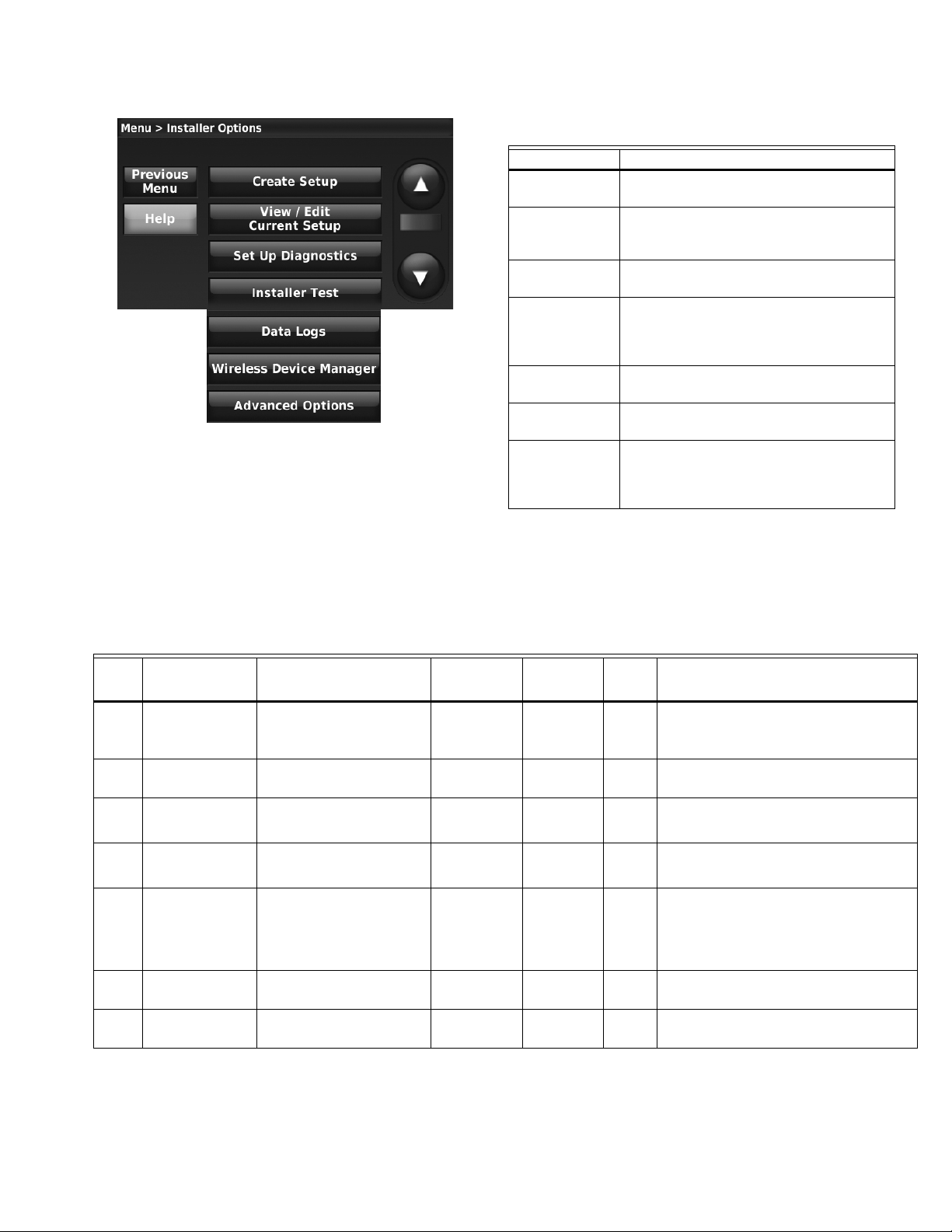
Fig. 39. Installer Options screen.
THX9321 PRESTIGE® 2.0 AND THX9421 PRESTIGE® IAQ 2.0 WITH EIM
Table 1. Installer Options.
Menu Item Description
Create Setup Press CREATE SETUP to set all system
settings one by one.
View/Edit
Current Setup
Press VIEW/EDIT CURRENT SETUP to
select a specific function and make quick
changes
Set Up
Diagnostics
Press SET UP DIAGNOSTICS to set up
and test Delta T diagnostics.
Installer Test Press INSTALLER TEST to quickly
determine if the heat, cool, fan and
thermostat are operating properly. Minimum
off timers are ignored during the test
Data Logs Press DATA LOGS to view the Alerts Log
and User Interactions Log.
Wireless Device
Manager
Advanced
Options
Press WIRELESS DEVICE MANAGER to
add or remove wireless accessories
Press ADVANCED OPTIONS to setup the
thermostat using a USB device or to restore
the thermostat to the factory default
settings.
NOTE: You can use the thermostat USB port to download
all Installer Setup settings, including your company name and contact information. You can
upload this data to each thermostat you install, to
save time.
Table 2. Installer Setup (ISU) Table.
ISU
Number Installer Setup Name Settings Default
1000 Language English
Français
Español
1010 Application Residential
Commercial
1020 Zone Number 1-16 1 Both No This ISU is only displayed on a thermostat that is
1030 Device Name [Enter Device Name] Thermostat Both No The Portable Comfort Control remote and Web
1030 Display on Home
1040 Scheduling Options Non-Programmable
1050 Temperature
Screen
Indication Scale
No
Yes
(select check box)
Programmable
Fahrenheit
Celsius
English Both No
Residential Both No
No Commercial No Thermostat location (name) can be displayed on the
Programmable Both No
Fahrenheit Both No
Residential,
Commercial
or Both
Requires
EIM Notes
controlling a zone panel through the THM4000
Wireless Adapter.
Interface displays the name of the thermostat that
you enter on this screen.
home screen. This feature is typically used when
multiple thermostat's are mounted in a manager's
office or equipment room. This allows you to
quickly identify which thermostat is in control of a
specific zone or area.
15 68-0311—01
Page 16

THX9321 PRESTIGE® 2.0 AND THX9421 PRESTIGE® IAQ 2.0 WITH EIM
Table 2. Installer Setup (ISU) Table. (Continued)
ISU
Number Installer Setup Name Settings Default
1060 Outdoor Air Sensor No
Yes
2000 Heating System Type Conventional Forced Air Heat
Heat Pump
Radiant Heat
Other
None (Cool Only)
2010 Heating Equipment
Type
Conventional Forced Air Heat:
Standard Efficiency Gas Forced Air
High Efficiency Gas Forced Air
Oil Forced Air
Electric Forced Air
Hot Water Fan Coil
Other
No Both No This ISU automatically defaults to Yes when a
Conventional
Forced Air Heat
Default varies
based on
previous
selections
Residential,
Commercial
or Both
Both No
Both No Cycle Rate and Fan Operation automatically default
Requires
EIM Notes
Wireless Outdoor Sensor is connected.
An Outdoor Sensor is required to set the following
ISUs:
ISU 3120 Outdoor Temperature Lockouts
(Compressor Lockout and Backup Heat Lockout)
ISU 4050 Outdoor Temperature used with Minimum
Heat Recovery Ramp Rate
ISU 4060 Outdoor Temperature used with
Maximum Heat Recovery Ramp Rate
ISU 4070 Outdoor Temperature used with Minimum
Cool Recovery Ramp Rate
ISU 4080 Outdoor Temperature used with
Maximum Cool Recovery Ramp Rate
ISU 8050 Humidification - Window Protection
ISU 10130 Ventilation Low Temperature Lockout
ISU 10130 Ventilation High Temperature Lockout
ISU 10130 Ventilation High Dew Point Lockout
(requires Wireless Outdoor Sensor)
ISU 13070 Allow Heat Delta T Diagnostics when
Outdoor Temperature is [Out. Temp. Range]
ISU 13080 Allow Heat Delta T Diagnostics when
Outdoor Humidity is [Out. Humidity Range]
ISU 13110 Allow Backup Heat Delta T Diag. when
Outdoor Temperature is [Out. Temp. Range]
ISU 13120 Allow Backup Heat Delta T Diagnostics
when Outdoor Humidity is [Out. Humidity Range]
ISU 13150 Allow Cool Delta T Diagnostics when
Outdoor Temperature is [Out. Temp. Range]
ISU 13160 Allow Cool Delta T Diagnostics when
Outdoor Temperature is [Out. Humidity Range]
to the correct settings based on the equipment type
selected.
This ISU is not displayed when ISU 2000 Heating
System Type is set to None (Cool Only).
See “Geothermal Radiant Heat” beginning on
page 62.
Heat Pump:
Air to Air Heat Pump
Geothermal Heat Pump
Geothermal Radiant Heat
Radiant Heat:
Hot Water Radiant Heat
Geothermal Radiant Heat
Steam
Other
Other:
Gravity
Other
68-0311—01 16
Page 17

THX9321 PRESTIGE® 2.0 AND THX9421 PRESTIGE® IAQ 2.0 WITH EIM
Table 2. Installer Setup (ISU) Table. (Continued)
ISU
Number Installer Setup Name Settings Default
2030 What Terminals are
2040 What Terminals are
2050 Geothermal Forced
2060 Reversing Valve O/B O (O/B on Cool)
2070 Cool Stages /
2020,
2070
Wired to Radiant
Heat?
Wired to Radiant Heat
- Stage 2?
Air System
Compressor Stages
Heat Stages / Backup
Heat Stages
None
U1
U2
U3
None
U1
U2
U3
None
Used for Cooling Only
Used for Heating and Cooling
B (O/B on Heat)
1-4 1 if ISU 1010 is
1 - 3 Default is 1 stage
Default varies
based on
previous
selections
Default varies
based on
previous
selections
Used for Heating
and Cooling
O/B on Cool Both No Only displayed if the equipment type is Air to Air
Residential
2 if ISU 1010 is
Commercial
if ISU 1010
Application is
Residential
Default is 2
stages if ISU
1010 Application
is Commercial
Residential,
Commercial
or Both
Both No This ISU is only displayed when ISU 2010 Heating
Both No This ISU is only displayed when ISU 2010 Heating
Both No This thermostat has the capability of controlling
Both No Conventional:
Both No Maximum of 3 Heat Stages for conventional
Requires
EIM Notes
Equipment Type is Geothermal Radiant Heat.
Geothermal Radiant Heat must be wired to a
universal terminal (U1, U2, or U3).
U1, U2 and U3 are normally open dry contacts when
configured for a stage of Heat. U1, U2 and U3
require power from the system transformer or a
separate transformer.
U3 is only available on the Equipment Interface
Module (EIM).
Geothermal Radiant Heat, Geothermal Forced Air
and Backup Heat.
If this thermostat is not controlling the Geothermal
Forced Air System, select None. This setting is
typically used if the thermostat is only controlling
Geothermal Radiant Heat.
If this thermostat is using the Geothermal Forced
Air System for cooling and not for heating, select
Used for Cooling Only.
If this thermostat is using the Geothermal Forced
Air System for both heating and cooling, select
Used for Heating and Cooling.
Heat Pump, Geothermal Heat Pump or Geothermal
Radiant Heat.
Cool Stage 3 and 4 are only available if ISU 1010 is
Commercial.
Cool Stage 3 and 4 must be wired to a universal
terminal (U1, U2 or U3).
Heat Pumps:
Maximum of 2 Compressor Stages for heat pump
systems.
systems.
Maximum of 2 Backup Heat Stages for systems with
more than 1 heating equipment type.
17 68-0311—01
Page 18

THX9321 PRESTIGE® 2.0 AND THX9421 PRESTIGE® IAQ 2.0 WITH EIM
Table 2. Installer Setup (ISU) Table. (Continued)
ISU
Number Installer Setup Name Settings Default
2080 What Terminals are
2090 What Terminals are
2100 What Terminals are
2110 Fan Operation in Heat No Fan
2120 Backup Heat Type None
2130 Backup Heat Stages 0 - 2 1 Both No This ISU is only displayed when a backup heat
Wired to Cool - Stage
3?
Wired to Cool - Stage
4?
Wired to Heat - Stage
3?
None
U1
U2
U3
None
U1
U2
U3
None
U1
U2
U3
Equipment Controls Fan
Thermostat Controls Fan
Standard Efficiency Gas Forced Air
High Efficiency Gas Forced Air
Oil Forced Air
Electric Forced Air
Hot Water Fan Coil
Hot Water Radiant Heat
Other
Default varies
based on
previous
selections
Default varies
based on
previous
selections
Default varies
based on
previous
selections
Thermostat
Controls Fan
None Both No This ISU is only displayed when ISU 2010 Heating
Residential,
Commercial
or Both
Commercial No Cool Stage 3 is only available if ISU 1010 is
Commercial No Cool Stage 4 is only available if ISU 1010 is
Both No THX9321 Thermostat Only:
Both No This ISU is only displayed when ISU 2010 Heating
Requires
EIM Notes
Commercial.
Cool Stage 3 must be wired to a universal terminal
(U1, U2 or U3).
U1, U2 and U3 are normally open dry contacts when
configured for a stage of Cool. U1, U2 and U3
require power from a system transformer or a
separate transformer.
U3 is only available on the Equipment Interface
Module (EIM).
Commercial.
Cool Stage 4 must be wired to a universal terminal
(U1, U2 or U3).
U1, U2 and U3 are normally open dry contacts when
configured for a stage of Cool. U1, U2 and U3
require power from a system transformer or a
separate transformer.
U3 is only available on the Equipment Interface
Module (EIM).
This ISU is only displayed on the THX9321
thermostat when it is wired directly to the
equipment (Equipment Interface Module is NOT
used).
Heat Stage 3 must be wired to a universal terminal
(U1 or U2).
U1 and U2 are normally open dry contacts when
configured for a stage of Heat. U1 and U2 require
power from a system transformer or a separate
transformer.
Equipment Type is Electric Forced Air, Hot Water
Fan Coil or Other.
The thermostat automatically defaults to Equipment
Controls Fan when ISU 2010 Heating Equipment
Type is Standard Efficiency Gas Forced Air, High
Efficiency Gas Forced Air or Oil Forced Air.
No Fan is only displayed when ISU 2010 Heating
Equipment Type is Other.
Equipment Type is Hot Water Radiant Heat,
Steam, Hot Water Fan Coil, Electric Forced Air or
Other.
The list of Backup Heat Types will vary based on the
type of primary heat selected at ISU 2010 Heating
Equipment Type.
When ISU 2010 Heating Equipment Type is Hot
Water Radiant Heat, the thermostat keeps the Hot
Water Radiant Heat on when it calls for Backup
Heat.
When ISU 2010 Heating Equipment Type is Steam,
the thermostat keeps the Steam Heat on when it
calls for Backup Heat.
When ISU 2010 Heating Equipment Type is Hot
Water Fan Coil, Electric Forced Air or Other, you
can select how the backup operates. See ISU 2150
Backup Heat Operation.
source is selected at ISU 2120 Backup Heat Type.
Maximum of 2 Backup Heat stages.
68-0311—01 18
Page 19

THX9321 PRESTIGE® 2.0 AND THX9421 PRESTIGE® IAQ 2.0 WITH EIM
Table 2. Installer Setup (ISU) Table. (Continued)
ISU
Number Installer Setup Name Settings Default
2140 What Terminals are
2150 Backup Heat
2160 Backup Heat Fan
2170 What Terminals are
2180 Backup Heat Type Electric Forced Air
Wired to Backup
Heat?
Operation
Operation
Wired to Backup Heat
- Stage 2?
None
U1
U2
NOT Allowed to Run with Primary
Heat
Allowed to Run with Primary Heat
No Fan
Equipment Controls Fan
Thermostat Controls Fan
None
U1
U2
Standard Efficiency Gas Forced Air
High Efficiency Gas Forced Air
Oil Forced Air
Hot Water Fan Coil
Hot Water Radiant Heat
Other
Default varies
based on
previous
selections
NOT allowed to
run with Primary
Heat
Thermostat
Controls Fan
Default varies
based on
previous
selections
Electric Forced
Air
Residential,
Commercial
or Both
Both No THX9321 Thermostat Only:
Both No This ISU is only displayed when ISU 2010 Heating
Both No This ISU is only displayed for conventional systems
Both No THX9321 Thermostat Only:
Both No This ISU is only displayed when ISU 2010 Heating
Requires
EIM Notes
This ISU is only displayed on the THX9321
thermostat when it is wired directly to the
equipment (Equipment Interface Module is NOT
used).
The thermostat can support up to 3 conventional
heat stages. When there are a total of 3
conventional heat stages, the last stage of heat
must be wired to U1 or U2.
U1 and U2 are normally open dry contacts when
configured for a stage of Heat. U1 and U2 require
power from a system transformer or a separate
transformer.
Equipment Type is Hot Water Fan Coil, Electric
Forced Air or Other.
When ISU 2010 Heating Equipment Type is Hot
Water Fan Coil, Electric Forced Air or Other, you
can select how the Backup Heat operates. The
thermostat can be setup to keep the primary heat
source on when it calls for Backup Heat or the
thermostat can be setup to turn off the primary heat
source when it calls for Backup Heat.
When ISU 2010 Heating Equipment Type is Hot
Water Radiant Heat, the thermostat keeps the Hot
Water Radiant Heat on when it calls for Backup
Heat.
When ISU 2010 Heating Equipment Type is Steam,
the thermostat keeps the Steam Heat on when it
calls for Backup Heat.
when ISU 2120 Backup Heat Type is Electric Forced
Air, Hot Water Fan Coil or Other.
Backup Heat Fan Operation automatically defaults to
Equipment Controls Fan when ISU 2120 Backup
Heat Type is Standard Efficiency Gas Forced Air,
High Efficiency Gas Forced Air or Oil Forced Air.
No Fan is only displayed when ISU 2120 Backup
Heat Type is Other.
This ISU is only displayed on the THX9321
thermostat when it is wired directly to the
equipment (Equipment Interface Module is NOT
used).
The thermostat can support up to 2 backup heat
stages for heat pump applications. When there are 2
backup heat stages, backup heat stage 2 must be
wired to U1 or U2.
U1 and U2 are normally open dry contacts when
configured for a stage of Heat. U1 and U2 require
power from a system transformer or a separate
transformer.
Equipment Type is Air to Air Heat Pump,
Geothermal Heat Pump or Geothermal Radiant
Heat and there is at least one stage of backup heat.
See “Heat Pump and Backup Heat Operation”
beginning on page 62.
19 68-0311—01
Page 20

THX9321 PRESTIGE® 2.0 AND THX9421 PRESTIGE® IAQ 2.0 WITH EIM
Table 2. Installer Setup (ISU) Table. (Continued)
ISU
Number Installer Setup Name Settings Default
2190 External Fossil Fuel
2200 Backup Heat
2210 Backup Heat Fan
2220 A-L/A Terminal Setup None
3000 Changeover Manual
Kit
Operation
Operation
Thermostat Controls Backup Heat
External Fossil Fuel Kit Controls
Backup Heat
NOT allowed to Run with Heat
Pump
Allowed to Run with Heat Pump
No Fan
Equipment Controls Fan
Thermostat Controls Fan
Time Of Day
Economizer
Heat Pump Failure Indication
Automatic
Thermostat
Controls Backup
Heat
Default varies
based on
previous
selections
Default varies
based on
previous
selections
None Commercial No This ISU is only displayed when ISU 1010
Manual:
if ISU 1010 is
Residential
Automatic:
if ISU 1010 is
Commercial
Residential,
Commercial
or Both
Both No This ISU is only displayed when ISU 2010 Heating
Both No This ISU is only displayed when ISU 2010 Heating
Both No This ISU is only displayed for heat pumps when ISU
Both No Manual: The user must select heating or cooling as
Requires
EIM Notes
Equipment Type is Air to Air Heat Pump,
Geothermal Heat Pump or Geothermal Radiant
Heat and ISU 2180 Backup Heat Type is Standard
Efficiency Gas Forced Air, High Efficiency Gas
Forced Air or Oil Forced Air.
Equipment Type is Air to Air Heat Pump,
Geothermal Heat Pump or Geothermal Radiant
Heat and ISU 2180 Backup Heat Type is Hot Water
Fan Coil or Other.
Not Allowed to Run with Heat Pump: The
thermostat turns off the heat pump when it calls for
backup heat.
Allowed to Run with Heat Pump: The thermostat
keeps the heat pump on when it calls for backup
heat.
2180 Backup Heat Type is Other.
Backup Heat Fan Operation:
Electric Forced Air: Thermostat Controls Fan
Standard Efficiency Gas Forced Air: Equipment
Controls Fan
High Efficiency Gas Forced Air: Equipment Controls
Fan
Oil Forced Air: Equipment Controls Fan
Hot Water Fan Coil: Thermostat Controls Fan
Hot Water Radiant Heat: Not Applicable
Application is Commercial.
None: The A-L/A terminal is not used.
Time of Day: The A-L/A terminal is energized during
Occupied periods and when the user overrides the
temperature. The terminal is de-energized during
Unoccupied periods and in Standby mode.
Economizer: The thermostat controls an
economizer module to provide ventilation during
Occupied periods and free cooling when outdoor
conditions are favorable. The A-L/A terminal is
energized during Occupied periods and during a call
for cooling in Unoccupied periods. See “Economizer
and Time of Day (TOD) Operation” beginning on
page 91.
Notes: The economizer module determines when
outdoor conditions are favorable for free cooling.
Delta T Diagnostics is not available when the
thermostat is setup for an Economizer.
Heat Pump Failure Indication: When 24 volts is
detected on the L/A terminal (compressor monitor),
the thermostat displays a message to alert the user
when the heat pump requires service. The L/A
terminal sends a continuous output to a zone panel
when the thermostat is set to Emergency Heat
mode. The zone panel will not turn on the heat
pump when a zone is set to Emergency Heat mode.
needed to maintain the desired indoor temperature.
Automatic: The user has the option to select Auto
for the system setting. In Auto mode, the
thermostat controls heating and cooling equipment
as needed to maintain the desired indoor
temperature.
68-0311—01 20
Page 21

THX9321 PRESTIGE® 2.0 AND THX9421 PRESTIGE® IAQ 2.0 WITH EIM
Table 2. Installer Setup (ISU) Table. (Continued)
ISU
Number Installer Setup Name Settings Default
3000 Deadband 2° F to 9° F (in 1° F increments) 3° F Both No This ISU is only displayed when ISU 3000 is set to
3010 Temperature Control
3020 Finish With High Cool
3021 Finish With High Heat
3030 Staging Control -
Options
Stage
Stage
Cool Differential
Stage 2
Basic Options
Advanced Options
Advanced Options + PID Settings
No
Yes
No
Yes
Comfort
1.0° F to 3.5° F from setpoint (in
0.5° F increments)
Basic Options Both No Basic Options: The Installer Setup displays basic
No Both No ISU 3010 Temperature Control Options must be set
No Both No ISU 3010 Temperature Control Options must be set
Comfort Both No ISU 3010 Temperature Control Options must be set
Residential,
Commercial
or Both
Requires
EIM Notes
Automatic.
Deadband is the minimum separation between heat
and cool settings when the thermostat is setup for
Auto Changeover. For example, if the deadband is
set to 3° F and the cool setpoint is 75° F, the
warmest heat setpoint allowed would be 72° F. If the
heat setpoint is adjusted above 72° F, it will
automatically adjust the cooling setpoint higher to
maintain the 3° F deadband.
temperature control options which include Backup
Heat Differential, Backup Heat Upstage Timer and
Outdoor Temperature Lockouts. Note: Outdoor
Temperature Lockouts only apply to Heat Pump
applications.
Advanced Options: The Installer Setup displays
both Basic and Advanced Options. Advanced
temperature control options include Finish With
High Cool Stage, Finish With High Heat Stage,
Temperature Differential settings between all stages
and Cycle Rate settings per stage.
Advanced Options+PID Settings: The Installer
Setup displays both Basic and Advanced Options
including PID settings which allow you to adjust the
integral, derivative and throttling range.
to Advanced to view or adjust Finish With High
Cool Stage.
This ISU is only displayed when the thermostat is
set for 2 or more cool stages.
When set to Yes, this feature keeps the high stage
of the cooling equipment running until the desired
setpoint is reached.
to Advanced to view or adjust Finish With High
Heat Stage.
This ISU is only displayed when the thermostat is
set for 2 or more heat stages.
When set to Yes, this feature keeps the high stage
of the heating equipment running until the desired
setpoint is reached.
to Advanced to view or adjust this ISU.
This ISU is only displayed when the thermostat is
set to 2 cool stages.
The indoor temperature must rise to the selected
differential setting before the thermostat turns on
the stage of cooling. For example, if stage 2 is set to
2° F (1.0° C), the indoor temperature must be 2° F
(1.0° C) away from the setpoint before stage 2 turns
on. When set to Comfort, the thermostat uses the
stage of cooling as needed to keep the indoor
temperature within 1° F (0.5° C) degree of the
setpoint.
21 68-0311—01
Page 22

THX9321 PRESTIGE® 2.0 AND THX9421 PRESTIGE® IAQ 2.0 WITH EIM
Table 2. Installer Setup (ISU) Table. (Continued)
ISU
Number Installer Setup Name Settings Default
3030 Staging Control -
3030 Staging Control -
3040 Staging Control -
3050 Staging Control -
3050 Staging Control -
Cool Differential
Stage 3
Cool Differential
Stage 4
Radiant Heat
Differential Stage 2
Heat Differential
Stage 2
Note: Depending on
the application, the
text displayed on the
screen may show the
specific heating
equipment type
Heat Differential
Stage 3
Note: Depending on
the application, the
text displayed on the
screen may show the
specific heating
equipment type
Comfort
1.0°F - 4.0°F from setpoint (in
0.5° F increments)
Comfort
1.0° F to 4.5° F from setpoint (in
0.5° F increments)
Comfort
1.0° F to 3.5° F from setpoint (in
0.5° F increments)
Comfort
1.0° F to 3.5° F from setpoint (in
0.5° F increments)
Comfort
1.0° F to 4.0° F from setpoint (in
0.5° F increments)
Comfort Commercial No ISU 3010 Temperature Control Options must be set
Comfort Commercial No ISU 3010 Temperature Control Options must be set
Comfort Both No ISU 3010 Temperature Control Options must be set
Comfort Both No ISU 3010 Temperature Control Options must be set
Comfort Both No ISU 3010 Temperature Control Options must be set
Residential,
Commercial
or Both
Requires
EIM Notes
to Advanced to view or adjust this ISU.
This ISU is only displayed when the thermostat is
set to 3 cool stages.
The indoor temperature must rise to the selected
differential setting before the thermostat turns on
the stage of cooling. For example, if stage 3 is set to
2° F (1.0° C), the indoor temperature must be 2° F
(1.0° C) away from the setpoint before stage 3 turns
on. When set to Comfort, the thermostat uses the
stage of cooling as needed to keep the indoor
temperature within 1° F (0.5° C) degree of the
setpoint.
to Advanced to view or adjust this ISU.
This ISU is only displayed when the thermostat is
set to 4 cool stages.
The indoor temperature must rise to the selected
differential setting before the thermostat turns on
the stage of cooling. For example, if stage 4 is set to
2° F (1.0° C), the indoor temperature must be 2° F
(1.0° C) away from the setpoint before stage 4 turns
on. When set to Comfort, the thermostat uses the
stage of cooling as needed to keep the indoor
temperature within 1° F (0.5° C) degree of the
setpoint.
to Advanced to view or adjust this ISU.
This ISU is only displayed if ISU 2010 Heating
Equipment Type is Geothermal Radiant Heat and
there are 2 radiant heat stages.
The indoor temperature must drop to the selected
differential setting before the thermostat will turn on
the stage of heating. For example, if stage 2 is set to
2° F (1.0° C), the indoor temperature must be 2° F
(1.0° C) away from the setpoint before stage 2 turns
on. When set to Comfort, the thermostat will use the
stage of heating as needed to keep the indoor
temperature within 1° F (0.5° C) degree of the
setpoint.
to Advanced to view or adjust this ISU.
This ISU is only displayed for conventional systems
that have 2 heat stages.
The indoor temperature must drop to the selected
differential setting before the thermostat will turn on
the stage of heating. For example, if stage 2 is set to
2° F (1.0° C), the indoor temperature must be 2° F
(1.0° C) away from the setpoint before stage 2 turns
on. When set to Comfort, the thermostat will use the
stage of heating as needed to keep the indoor
temperature within 1° F (0.5° C) degree of the
setpoint.
to Advanced to view or adjust this ISU.
This ISU is only displayed for conventional systems
that have 3 heat stages.
The indoor temperature must drop to the selected
differential setting before the thermostat will turn on
the stage of heating. For example, if stage 3 is set to
2° F (1.0° C), the indoor temperature must be 2° F
(1.0° C) away from the setpoint before stage 3 turns
on. When set to Comfort, the thermostat will use the
stage of heating as needed to keep the indoor
temperature within 1° F (0.5° C) degree of the
setpoint.
68-0311—01 22
Page 23

THX9321 PRESTIGE® 2.0 AND THX9421 PRESTIGE® IAQ 2.0 WITH EIM
Table 2. Installer Setup (ISU) Table. (Continued)
ISU
Number Installer Setup Name Settings Default
3060 Staging Control -
3060 Staging Control -
3080,
3090
3080,
3090
3110 Backup Heat Upstage
Compressor Heat
Differential Stage 1
Compressor Heat
Differential Stage 2
Staging Control Backup Heat
Differential Stage 1
Note: “Stage 1" is not
displayed if there is
only 1 stage of
Backup Heat.
Staging Control Backup Heat
Differential Stage 2
Timer
Comfort
1.0° F to 4.0° F from setpoint (in
0.5° F increments)
Comfort
1.0° F to 4.5° F from setpoint (in
0.5° F increments)
Comfort
2.0° F to 15.0° F from setpoint (in
0.5° F increments)
Comfort
2.0° F to 15.5° F from setpoint (in
0.5° F increments)
Off
(30, 45, 60, 75, 90) minutes
(2, 3, 4, 5, 6, 8, 10, 12, 14, 16)
hours
Comfort Both No ISU 3010 Temperature Control Options must be set
Comfort Both No ISU 3010 Temperature Control Options must be set
Comfort Both No A backup heat differential can be set on any system
Comfort Both No ISU 3010 Temperature Control Options must be set
Off Both No The Backup Heat Upstage Timer starts when the
Residential,
Commercial
or Both
Requires
EIM Notes
to Advanced to view or adjust this ISU.
This ISU is only displayed if ISU 2010 Heating
Equipment Type is Geothermal Radiant Heat and
ISU 2050 Geothermal Forced Air System is set to
Used for Heating and Cooling.
The indoor temperature must drop to the selected
differential setting before the thermostat will turn on
the stage of heating. For example, if stage 1 is set to
2° F (1.0° C), the indoor temperature must be 2° F
(1.0° C) away from the setpoint before stage 1 turns
on. When set to Comfort, the thermostat will use the
stage of heating as needed to keep the indoor
temperature within 1° F (0.5° C) degree of the
setpoint.
to Advanced to view or adjust this ISU.
This ISU is only displayed if ISU 2010 Heating
Equipment Type is Air to Air Heat Pump,
Geothermal Heat Pump or Geothermal Radiant
Heat and there are 2 compressor stages.
The indoor temperature must drop to the selected
differential setting before the thermostat will turn on
the stage of heating. For example, if stage 2 is set to
2° F (1.0° C), the indoor temperature must be 2° F
(1.0° C) away from the setpoint before stage 2 turns
on. When set to Comfort, the thermostat will use the
stage of heating as needed to keep the indoor
temperature within 1° F (0.5° C) degree of the
setpoint.
that has more than one heating equipment type.
See “Backup Heat Differential (Droop)” beginning
on page 60.
The Comfort setting is only available on systems
when the Backup Heat Type is Allowed to Run with
the Primary Heat (Heat Pump). For example, Heat
Pumps with Electric Forced Air Backup Heat.
The Comfort setting is NOT available for Dual Fuel
systems. For example, Heat Pumps with Gas Forced
Air.
to Advanced to view or adjust Backup Heat
Differential Stage 2.
This ISU is only displayed if there are 2 backup heat
stages.
The indoor temperature must drop to the selected
differential setting before the thermostat will turn on
backup heat stage 2. For example, if backup heat
stage 2 is set to 2° F (1.0° C), the indoor
temperature must be 2° F (1.0° C) away from the
setpoint before backup heat stage 2 turns on. When
set to Comfort, the thermostat will use backup heat
stage 2 as needed to keep the indoor temperature
within 1° F (0.5° C) degree of the setpoint.
highest stage of the previous heating equipment
type turns on. Backup heat will be used (if needed)
when the timer expires. See “Backup Heat Upstage
Timer” beginning on page 61.
This ISU is only displayed when Backup Heat
Differential Stage 1 is set to 2 F or higher (ISU 3080,
3090).
23 68-0311—01
Page 24

THX9321 PRESTIGE® 2.0 AND THX9421 PRESTIGE® IAQ 2.0 WITH EIM
Table 2. Installer Setup (ISU) Table. (Continued)
ISU
Number Installer Setup Name Settings Default
3120 Outdoor Temperature
3120 Outdoor Temperature
3130 Radiant Heat Cycles
3130 Radiant Heat Cycles
Lockouts:
Compressor Lockout
/ Balance Point
Lockouts:
Backup Heat Lockout
Per Hour - Stage 1
Note: “Stage 1" is not
displayed if there is
only 1 stage of
Radiant Heat.
Per Hour - Stage 2
Off
5° F to 60° F (in 5° F increments)
Off
5° F to 65° F (in 5° F increments)
1 to 12 CPH 3 Both No ISU 3010 Temperature Control Options must be set
1 to 12 CPH 3 Both No ISU 3010 Temperature Control Options must be set
Off
(See Notes)
Off Both No ISU 3120 Backup Heat Outdoor Temperature
Residential,
Commercial
or Both
Both No ISU 3120 Compressor Lockout / Balance Point
Requires
EIM Notes
requires an outdoor sensor.
Default is 40 F if ISU 2010 Heating Equipment Type
is Air to Air Heat Pump and ISU 2180 Backup Type
is gas or oil forced air.
Default is Off if ISU 2010 Heating Equipment Type is
Air to Air Heat Pump and ISU 2180 Backup Type is
electric forced air.
Default is Off if ISU 2010 Heating Equipment Type is
Geothermal Heat Pump or Geothermal Radiant
Heat.
Compressor Lockout / Balance Point is optional for
any type of heat pump (Air to Air Heat Pump,
Geothermal Heat Pump or Geothermal Radiant
Heat).
See “Heat pump with outdoor temperature
lockouts” beginning on page 62.
Lockout requires an outdoor sensor.
This ISU is only displayed if ISU 2010 Heating
Equipment Type is Air to Air Heat Pump,
Geothermal Heat Pump or Geothermal Radiant
Heat and ISU 2190 External fossil fuel kit is set to
Thermostat Controls Backup Heat.
See “Heat pump with outdoor temperature
lockouts” beginning on page 62.
to Advanced to view or adjust cycle rate.
This ISU is only displayed when ISU 2010 Heating
Equipment Type is Geothermal Radiant Heat.
The thermostat automatically defaults to the
recommended setting for Geothermal Radiant Heat
(3 CPH).
Cycle rate limits the maximum number of times the
system can cycle in a 1 hour period measured at a
50% load. For example, when set to 3 CPH, at a
50% load, the most the system will cycle is 3 times
per hour (10 minutes on, 10 minutes off). The
system cycles less often when load conditions are
less than or greater than a 50% load.
68-0311—01 24
Page 25

THX9321 PRESTIGE® 2.0 AND THX9421 PRESTIGE® IAQ 2.0 WITH EIM
Table 2. Installer Setup (ISU) Table. (Continued)
ISU
Number Installer Setup Name Settings Default
3140 Cool / Compressor
3140 Cool / Compressor
3140 Cool Cycles Per Hour
3140 Cool Cycles Per Hour
Cycles Per Hour Stage 1
Note: “Stage 1" is not
displayed if there is
only 1 stage.
Cycles Per Hour Stage 2
- Stage 3
- Stage 4
1 to 6 CPH 3 Both No ISU 3010 Temperature Control Options must be set
1 to 6 CPH 3 Both No ISU 3010 Temperature Control Options must be set
1 to 6 CPH 3 Commercial No ISU 3010 Temperature Control Options must be set
1 to 6 CPH 3 Commercial No ISU 3010 Temperature Control Options must be set
Residential,
Commercial
or Both
Requires
EIM Notes
to Advanced to view or adjust cycle rate.
This ISU is only displayed when ISU 2070 Cool /
Compressor Stages is set to 1 stage.
Cycle rate limits the maximum number of times the
system can cycle in a 1 hour period measured at a
50% load. For example, when set to 3 CPH, at a
50% load, the most the system will cycle is 3 times
per hour (10 minutes on, 10 minutes off). The
system cycles less often when load conditions are
less than or greater than a 50% load.
to Advanced to view or adjust cycle rate.
This ISU is only displayed when ISU 2070 Cool /
Compressor Stages is set to 2 stages.
Cycle rate limits the maximum number of times the
system can cycle in a 1 hour period measured at a
50% load. For example, when set to 3 CPH, at a
50% load, the most the system will cycle is 3 times
per hour (10 minutes on, 10 minutes off). The
system cycles less often when load conditions are
less than or greater than a 50% load.
to Advanced to view or adjust cycle rate.
This ISU is only displayed when ISU 1010
Application is set to Commercial and ISU 2070 Cool
Stages is set to 3 stages.
Cycle rate limits the maximum number of times the
system can cycle in a 1 hour period measured at a
50% load. For example, when set to 3 CPH, at a
50% load, the most the system will cycle is 3 times
per hour (10 minutes on, 10 minutes off). The
system cycles less often when load conditions are
less than or greater than a 50% load.
to Advanced to view or adjust cycle rate.
This ISU is only displayed when ISU 1010
Application is set to Commercial and ISU 2070 Cool
Stages is set to 4 stages.
Cycle rate limits the maximum number of times the
system can cycle in a 1 hour period measured at a
50% load. For example, when set to 3 CPH, at a
50% load, the most the system will cycle is 3 times
per hour (10 minutes on, 10 minutes off). The
system cycles less often when load conditions are
less than or greater than a 50% load.
25 68-0311—01
Page 26

THX9321 PRESTIGE® 2.0 AND THX9421 PRESTIGE® IAQ 2.0 WITH EIM
Table 2. Installer Setup (ISU) Table. (Continued)
ISU
Number Installer Setup Name Settings Default
3150 Heat Cycles Per Hour
3150 Heat Cycles Per Hour
- Stage 1
Note: Depending on
the application, the
text displayed on the
screen may show the
specific heating
equipment type.
“Stage 1" is not
displayed if there is
only 1 stage.
- Stage 2
Note: Depending on
the application, the
text displayed on the
screen may show the
specific heating
equipment type.
1 to 12 CPH Default varies
1 to 12 CPH Default varies
based on heating
equipment type
selected
based on heating
equipment type
selected
Residential,
Commercial
or Both
Both No ISU 3010 Temperature Control Options must be set
Both No ISU 3010 Temperature Control Options must be set
Requires
EIM Notes
to Advanced to view or adjust cycle rate.
This ISU is only displayed when ISU 2070 Heat
Stages is set to 1 stage.
Cycle rate limits the maximum number of times the
system can cycle in a 1 hour period measured at a
50% load. For example, when set to 3 CPH, at a
50% load, the most the system will cycle is 3 times
per hour (10 minutes on, 10 minutes off). The
system cycles less often when load conditions are
less than or greater than a 50% load. The
thermostat automatically defaults to the
recommended cycle rate based on the heating
equipment type that is used. You can change the
cycle rate as needed. Defaults for commonly used
systems are shown below.
Standard Efficiency Gas Forced Air = 5 CPH
High Efficiency Gas Forced Air = 3 CPH
Oil Forced Air = 5 CPH
Electric Forced Air = 9 CPH
Hot Water Fan Coil = 3 CPH
Hot Water Radiant Heat = 3 CPH
Geothermal Radiant Heat = 3 CPH
Steam = 1 CPH
Gravity = 1 CPH
to Advanced to view or adjust cycle rate.
This ISU is only displayed when ISU 2070 Heat
Stages is set to 2 stages.
Cycle rate limits the maximum number of times the
system can cycle in a 1 hour period measured at a
50% load. For example, when set to 3 CPH, at a
50% load, the most the system will cycle is 3 times
per hour (10 minutes on, 10 minutes off). The
system cycles less often when load conditions are
less than or greater than a 50% load. The
thermostat automatically defaults to the
recommended cycle rate based on the heating
equipment type that is used. You can change the
cycle rate as needed. Defaults for commonly used
systems are shown below.
Standard Efficiency Gas Forced Air = 5 CPH
High Efficiency Gas Forced Air = 3 CPH
Oil Forced Air = 5 CPH
Electric Forced Air = 9 CPH
Hot Water Fan Coil = 3 CPH
Hot Water Radiant Heat = 3 CPH
Geothermal Radiant Heat = 3 CPH
Steam = 1 CPH
Gravity = 1 CPH
68-0311—01 26
Page 27

THX9321 PRESTIGE® 2.0 AND THX9421 PRESTIGE® IAQ 2.0 WITH EIM
Table 2. Installer Setup (ISU) Table. (Continued)
ISU
Number Installer Setup Name Settings Default
3150 Heat Cycles Per Hour
3160 Backup Heat Cycles
- Stage 3
Note: Depending on
the application, the
text displayed on the
screen may show the
specific heating
equipment type.
Per Hour - Stage 1
Note: “Stage 1" is not
displayed if there is
only 1 stage.
1 to 12 CPH Default varies
1 to 12 CPH Default varies
based on heating
equipment type
selected
based on heating
equipment type
selected
Residential,
Commercial
or Both
Both No ISU 3010 Temperature Control Options must be set
Both No ISU 3010 Temperature Control Options must be set
Requires
EIM Notes
to Advanced to view or adjust cycle rate.
This ISU is only displayed when ISU 2070 Heat
Stages is set to 3 stages.
Cycle rate limits the maximum number of times the
system can cycle in a 1 hour period measured at a
50% load. For example, when set to 3 CPH, at a
50% load, the most the system will cycle is 3 times
per hour (10 minutes on, 10 minutes off). The
system cycles less often when load conditions are
less than or greater than a 50% load. The
thermostat automatically defaults to the
recommended cycle rate based on the heating
equipment type that is used. You can change the
cycle rate as needed. Defaults for commonly used
systems are shown below.
Standard Efficiency Gas Forced Air = 5 CPH
High Efficiency Gas Forced Air = 3 CPH
Oil Forced Air = 5 CPH
Electric Forced Air = 9 CPH
Hot Water Fan Coil = 3 CPH
Hot Water Radiant Heat = 3 CPH
Geothermal Radiant Heat = 3 CPH
Steam = 1 CPH
Gravity = 1 CPH
to Advanced to view or adjust cycle rate.
This ISU is only displayed when ISU 2070 or 2130
Backup Heat Stages is set to 1 stage.
Cycle rate limits the maximum number of times the
system can cycle in a 1 hour period measured at a
50% load. For example, when set to 3 CPH, at a
50% load, the most the system will cycle is 3 times
per hour (10 minutes on, 10 minutes off). The
system cycles less often when load conditions are
less than or greater than a 50% load. The
thermostat automatically defaults to the
recommended cycle rate based on the heating
equipment type that is used. You can change the
cycle rate as needed. Defaults for commonly used
systems are shown below.
Standard Efficiency Gas Forced Air = 5 CPH
High Efficiency Gas Forced Air = 3 CPH
Oil Forced Air = 5 CPH
Electric Forced Air = 9 CPH
Hot Water Fan Coil = 3 CPH
Hot Water Radiant Heat = 3 CPH
Geothermal Radiant Heat = 3 CPH
Steam = 1 CPH
Gravity = 1 CPH
27 68-0311—01
Page 28

THX9321 PRESTIGE® 2.0 AND THX9421 PRESTIGE® IAQ 2.0 WITH EIM
Table 2. Installer Setup (ISU) Table. (Continued)
ISU
Number Installer Setup Name Settings Default
3160 Backup Heat Cycles
3170 Cooling Throttling
3180 Cooling Integral 0, 100 to 25,000 sec 10,000 sec Commercial No The default Cooling Integral is 10,000 seconds
3190 Cooling Derivative 0, 100 to 25,000 sec 0 sec Commercial No The default Cooling Derivative is 0 seconds which is
3200 Heating Throttling
3210 Heating Integral 0, 100 to 25,000 sec 10,000 sec Commercial No The default Heating Integral is 10,000 seconds
3220 Heating Derivative 0, 100 to 25,000 sec 0 sec Commercial No The default Heating Derivative is 0 seconds which is
3240 Minimum
Per Hour - Stage 2
Range
Range
Compressor Off Time
1 to 12 CPH Default varies
1° F to 30° F 2° F Commercial No The default Cooling Throttling range is 2° F (1.5° C)
1° F to 30° F 2° F Commercial No The default Heating Throttling Range is 2° F (1.5° C)
Off
1 - 5 minutes
based on heating
equipment type
selected
5 minutes Both No The thermostat has a built in compressor protection
Residential,
Commercial
or Both
Both No ISU 3010 Temperature Control Options must be set
Requires
EIM Notes
to Advanced to view or adjust cycle rate.
This ISU is only displayed when ISU 2070 or 2130
Backup Heat Stages is set to 2 stages.
Cycle rate limits the maximum number of times the
system can cycle in a 1 hour period measured at a
50% load. For example, when set to 3 CPH, at a
50% load, the most the system will cycle is 3 times
per hour (10 minutes on, 10 minutes off). The
system cycles less often when load conditions are
less than or greater than a 50% load. The
thermostat automatically defaults to the
recommended cycle rate based on the heating
equipment type that is used. You can change the
cycle rate as needed. Default for commonly used
systems are shown below.
Standard Efficiency Gas Forced Air = 5 CPH
High Efficiency Gas Forced Air = 3 CPH
Oil Forced Air = 5 CPH
Electric Forced Air = 9 CPH
Hot Water Fan Coil = 3 CPH
Hot Water Radiant Heat = 3 CPH
Geothermal Radiant Heat = 3 CPH
Steam = 1 CPH
Gravity = 1 CPH
which is appropriate for most applications. Do not
change this setting unless advised to do so by
Honeywell technical support.
The throttling range controls the cycling of the
system and helps to compensate for load changes,
equipment sizing and thermostat mounting
location.
which is appropriate for most applications. Do not
change this setting unless advised to do so by
Honeywell technical support.
The integral controls how much droop is used.
appropriate for most applications. Do not change
this setting unless advised to do so by Honeywell
technical support.
The derivative makes adjustments to the algorithm
for fast acting systems.
which is appropriate for most applications. Do not
change this setting unless advised to do so by
Honeywell technical support.
The throttling range controls the cycling of the
system and helps to compensate for load changes,
equipment sizing and thermostat mounting
location.
which is appropriate for most applications. Do not
change this setting unless advised to do so by
Honeywell technical support.
The integral controls how much droop is used.
appropriate for most applications. Do not change
this setting unless advised to do so by Honeywell
technical support.
The derivative makes adjustments to the algorithm
for fast acting systems.
(minimum off timer) that prevents the compressor
from restarting too early after a shutdown. The
minimum-off timer is activated after the
compressor turns off.
If there is a call during the minimum-off timer, the
thermostat shows “waiting for equipment” in the
display.
68-0311—01 28
Page 29

THX9321 PRESTIGE® 2.0 AND THX9421 PRESTIGE® IAQ 2.0 WITH EIM
Table 2. Installer Setup (ISU) Table. (Continued)
ISU
Number Installer Setup Name Settings Default
3260 Extended Fan Run
3260 Extended Fan Run
4000 Number Of Schedule
4010 Pre-Occupancy Purge
4020 Type of Override Standard
4030 Override Duration No Limit
4050 Minimum Heat
Time in Cool
Time in Heat
Periods
Duration
Recovery Ramp Rate
0, 30, 60, 90 seconds, 2, 3, 4, 5,
6, 7, 8, 9, 10, 11, 12, 13, 14, 15
minutes
0, 30, 60, 90 seconds, 2, 3, 4, 5,
6, 7, 8, 9, 10, 11, 12, 13, 14, 15
minutes
2 or 4 periods per day 4 periods per day Both No Residential:
Off
1 hour
2 hour
3 hour
Initiate Occupancy
1 to 12 Hours
Off
1° F/hr to 20° F/hr
0 seconds Both No After the call for cooling ends, the thermostat keeps
0 seconds Both No After the call for heating ends, the thermostat keeps
Off Commercial No Runs the fan 1 to 3 hours before each occupied
Standard Commercial No Standard:
3 hours Commercial No When the user presses the OVERRIDE button, the
5° F/hr Commercial No Off: The heating system will begin recovery at the
Residential,
Commercial
or Both
Requires
EIM Notes
the fan on for the selected amount of time for
increased efficiency. This may re-introduce
humidity into the living space.
the fan on for the selected amount of time for
increased efficiency.
4 Periods = Wake, Leave, Return, Sleep
2 Periods = Wake, Sleep
Commercial:
4 Periods = Occupied 1, Unoccupied 1, Occupied 2,
Unoccupied 2
2 Periods = Occupied 1, Unoccupied 1
period to provide a comfortable workplace upon
arrival.
The system maintains temperatures programmed
for the occupied and unoccupied time periods.
Pressing OVERRIDE will allow the user to make a
temporary schedule change.
Initiate Occupancy:
The system maintains temperature at an energy
saving level until the Press to Start Occupancy
button is pressed by the user. The system will then
maintain a comfortable temperature until the
occupied period ends. This option is recommended
for cost savings when the workplace is used
infrequently or arrival times change from day to day
(example - schools). Once the occupancy is
activated by pressing the Press to Start Occupancy
button, the user will still be able to perform a
standard OVERRIDE of the schedule.
thermostat will maintain the new temperature for at
least 1 hour. The user can adjust the Hold Until time
from 1 hour to the amount set for the Override
Duration (1-12 hours). Default setting is 3 hours. If
set to No Limit, the user can adjust the Hold Until
time up to 24 hours.
time that is scheduled.
When a Minimum Recovery Ramp Rate is set, the
thermostat will begin recovery early to ensure the
temperature is reached at the scheduled time.
Set a Minimum Recovery Ramp Rate based on the
rate that the heating system can recover at for a
cold day in your region. Default setting is 5° F /
hour.
If an outdoor sensor is installed, set an Outdoor
Temperature that is representative of a cold day in
your region to be associated with the Minimum
Recovery Ramp Rate. The thermostat will begin
recovery at the optimal time based on a calculated
ramp rate, allowing the system to recover on time
and save energy during changing outdoor
conditions.
During recovery, the setpoint changes at a rate in
degrees per hour depending on the outdoor
temperature. If there is no outdoor sensor, the
Minimum Recovery Ramp Rate is used.
29 68-0311—01
Page 30

THX9321 PRESTIGE® 2.0 AND THX9421 PRESTIGE® IAQ 2.0 WITH EIM
Table 2. Installer Setup (ISU) Table. (Continued)
ISU
Number Installer Setup Name Settings Default
4050 Outdoor Temperature
4060 Maximum Heat
4060 Outdoor Temperature
used with Minimum
Heat Recovery Ramp
Rate
Recovery Ramp Rate
used with Maximum
Heat Recovery Ramp
Rate
Off
-20° F to 100°F
Off
1° F/hr to 20° F/hr
Off
-20° F to 100° F
0° F Commercial No Off: The heating system will begin recovery at the
8° F/hr Commercial No Off: The heating system will begin recovery at the
40° F Commercial No Off: The heating system will begin recovery at the
Residential,
Commercial
or Both
Requires
EIM Notes
time that is scheduled.
When a Minimum Recovery Ramp Rate is set, the
thermostat will begin recovery early to ensure the
temperature is reached at the scheduled time.
Set a Minimum Recovery Ramp Rate based on the
rate that the heating system can recover at for a
cold day in your region. Default setting is 5° F /
hour.
If an outdoor sensor is installed, set an Outdoor
Temperature that is representative of a cold day in
your region to be associated with the Minimum
Recovery Ramp Rate. The thermostat will begin
recovery at the optimal time based on a calculated
ramp rate, allowing the system to recover on time
and save energy during changing outdoor
conditions.
During recovery, the setpoint changes at a rate in
degrees per hour depending on the outdoor
temperature. If there is no outdoor sensor, the
Minimum Recovery Ramp Rate is used.
time that is scheduled.
When a Maximum Recovery Ramp Rate is set, the
thermostat will begin recovery early to ensure the
temperature is reached at the scheduled time.
Set a Maximum Recovery Ramp Rate based on the
rate that the heating system can recover at for a
mild day in your region. Default setting is 8° F /
hour.
Set an Outdoor Temperature that is representative
of a mild day in your region to be associated with
the Maximum Recovery Ramp Rate. The
thermostat will begin recovery at the optimal time
based on a calculated ramp rate, allowing the
system to recover on time and save energy during
changing outdoor conditions.
During recovery, the setpoint changes at a rate in
degrees per hour depending on the outdoor
temperature.
68-0311—01 30
Page 31

THX9321 PRESTIGE® 2.0 AND THX9421 PRESTIGE® IAQ 2.0 WITH EIM
Table 2. Installer Setup (ISU) Table. (Continued)
ISU
Number Installer Setup Name Settings Default
4070 Minimum Cool
4070 Outdoor Temperature
4080 Maximum Cool
Recovery Ramp Rate
used with Minimum
Cool Recovery Ramp
Rate
Recovery Ramp Rate
Off
1° F/hr to 20° F/hr
Off
-20° F to 100° F
Off
1° F/hr to 20° F/hr
3° F/hr Commercial No Off: The cooling system will begin recovery at the
90° F Commercial No Off: The cooling system will begin recovery at the
6° F/hr Commercial No Off: The cooling system will begin recovery at the
Residential,
Commercial
or Both
Requires
EIM Notes
time that is scheduled.
When a Minimum Recovery Ramp Rate is set, the
thermostat will begin recovery early to ensure the
temperature is reached at the scheduled time.
Set a Minimum Recovery Ramp Rate based on the
rate that the cooling system can recover at for a hot
day in your region. Default setting is 3° F / hour.
If an outdoor sensor is installed, set an Outdoor
Temperature that is representative of a hot day in
your region to be associated with the Minimum
Recovery Ramp Rate. The thermostat will begin
recovery at the optimal time based on a calculated
ramp rate, allowing the system to recover on time
and save energy during changing outdoor
conditions.
During recovery, the setpoint changes at a rate in
degrees per hour depending on the outdoor
temperature. If there is no outdoor sensor, the
Minimum Recovery Ramp Rate is used.
time that is scheduled.
When a Maximum Recovery Ramp Rate is set, the
thermostat will begin recovery early to ensure the
temperature is reached at the scheduled time.
Set a Maximum Recovery Ramp Rate
rate that the cooling system can recover at for a
mild day in your region. Default setting is 6° F /
hour.
Set an Outdoor Temperature that is representative
of a mild day in your region to be associated with
the Maximum Recovery Ramp Rate.
The thermostat will begin recovery at the optimal
time based on a calculated ramp rate, allowing the
system to recover on time and save energy during
changing outdoor conditions.
During recovery, the setpoint changes at a rate in
degrees per hour depending on the outdoor
temperature.
based on the
31 68-0311—01
Page 32

THX9321 PRESTIGE® 2.0 AND THX9421 PRESTIGE® IAQ 2.0 WITH EIM
Table 2. Installer Setup (ISU) Table. (Continued)
ISU
Number Installer Setup Name Settings Default
4080 Outdoor Temperature
4090 Adaptive Intelligent
4100 Minimum Cool
4100 Maximum Heat
4110 Keypad Lockout Unlocked
4120 Residential:
4120 Residential:
4130 Residential:
used with Maximum
Cool Recovery Ramp
Rate
Recovery
Setpoint
Setpoint
Entry / Exit Remote Home Cool Setpoint
Commercial:
Entry / Exit Remote Occupied Cool
Setpoint
Entry / Exit Remote Home Heat Setpoint
Commercial:
Entry / Exit Remote Occupied Heat
Setpoint
Entry / Exit Remote Away Cool Setpoint
Commercial:
Entry / Exit Remote Unoccupied Cool
Setpoint
Off
-20° F to 100°F
No
Yes
50° F to 99° F 50° F Both No The user cannot set the temperature below this
40° F to 90° F 90° F Both No The user cannot set the temperature above this
Partially Locked
Fully Locked
None
50° F to 99° F
Note: setpoint is limited based on
setting at ISU 4100.
None
40° F to 90° F
Note: setpoint is limited based on
setting at ISU 4100.
None
50° F to 99° F
Note: setpoint is limited based on
setting at ISU 4100.
70° F Commercial No Off: The cooling system will begin recovery at the
Yes Residential No No: The system will begin heating or cooling
Unlocked Both No Unlocked: User has access to all thermostat
75° F Both No The thermostat maintains this Cool setting when the
70° F Both No The thermostat maintains this Heat setting when the
78° F Both No The thermostat maintains this Cool setting when the
Residential,
Commercial
or Both
Requires
EIM Notes
time that is scheduled.
When a Maximum Recovery Ramp Rate is set, the
thermostat will begin recovery early to ensure the
temperature is reached at the scheduled time.
Set a Maximum Recovery Ramp Rate based on the
rate that the cooling system can recover at for a
mild day in your region. Default setting is 6° F /
hour.
Set an Outdoor Temperature that is representative
of a mild day in your region to be associated with
the Maximum Recovery Ramp Rate.
The thermostat will begin recovery at the optimal
time based on a calculated ramp rate, allowing the
system to recover on time and save energy during
changing outdoor conditions.
During recovery, the setpoint changes at a rate in
degrees per hour depending on the outdoor
temperature.
recovery at the scheduled time.
Yes: The thermostat will begin heating or cooling
recovery early to ensure that the temperature is
reached at the scheduled time. The thermostat will
adjust the start time of the equipment based on how
quickly the scheduled temperature was reached on
previous days.
level.
level.
settings.
Partially Locked: User can modify only temperature
settings.
Fully Locked: User cannot modify any settings.
user presses Home / Occupied at the Entry / Exit
Remote. Select None to delete this temperature
setting. The thermostat only responds to the Entry /
Exit Remote if a temperature is pre-set at this
screen. See “Wireless Entry/Exit Remote” beginning
on page 94.
user presses Home / Occupied at the Entry / Exit
Remote. Select None to delete this temperature
setting. The thermostat only responds to the Entry /
Exit Remote if a temperature is pre-set at this
screen. See “Wireless Entry/Exit Remote” beginning
on page 94.
user presses Away / Unoccupied at the Entry / Exit
Remote. Select None to delete this temperature
setting. The thermostat only responds to the Entry /
Exit Remote if a temperature is pre-set at this
screen. See “Wireless Entry/Exit Remote” beginning
on page 94.
68-0311—01 32
Page 33

THX9321 PRESTIGE® 2.0 AND THX9421 PRESTIGE® IAQ 2.0 WITH EIM
Table 2. Installer Setup (ISU) Table. (Continued)
ISU
Number Installer Setup Name Settings Default
4130 Residential:
4140 Residential:
4140 Residential:
5000 What Sensors are
5010 Indoor Temperature
5020 What Terminals are
5030 Indoor Temperature
Entry / Exit Remote Away Heat Setpoint
Commercial:
Entry / Exit Remote Unoccupied Heat
Setpoint
Entry / Exit Remote Vacation Cool
Setpoint
Commercial:
Entry / Exit Remote Holiday Cool Setpoint
Entry / Exit Remote Vacation Heat
Setpoint
Commercial:
Entry / Exit Remote Holiday Heat Setpoint
WIRED to your
System?
Sensor Name
Wired to the Indoor
Temperature Sensor?
Sensor Type
None
40° F to 90° F
Note: setpoint is limited based on
setting at ISU 4100.
None
50° F to 99° F
Note: setpoint is limited based on
setting at ISU 4100.
None
40° F to 90° F
Note: setpoint is limited based on
setting at ISU 4100.
Check box on screen for each:
Indoor Air Temperature
Outdoor Air Temperature
Return Air Temperature
Discharge Air Temperature
[Sensor Name] Indoor Sensor Both Yes Wired Sensors requires an EIM (Equipment
None
S1
S2
10K
20K
65° F Both No The thermostat maintains this Heat setting when the
82° F Both No The thermostat maintains this Cool setting when the
60° F Both No The thermostat maintains this Heat setting when the
None Both Yes Wired Sensors requires an EIM (Equipment
None Both Yes Wired Sensors requires an EIM (Equipment
10K:
if ISU 1010
Application is
Residential
20K:
if ISU 1010:
Application is
Commercial
Residential,
Commercial
or Both
Both Yes Wired Sensors requires an EIM (Equipment
Requires
EIM Notes
user presses Away / Unoccupied at the Entry / Exit
Remote. Select None to delete this temperature
setting. The thermostat only responds to the Entry /
Exit Remote if a temperature is pre-set at this
screen. See “Wireless Entry/Exit Remote” beginning
on page 94.
user presses Vacation / Holiday at the Entry / Exit
Remote. Select None to delete this temperature
setting. The thermostat only responds to the Entry /
Exit Remote if a temperature is pre-set at this
screen. See “Wireless Entry/Exit Remote” beginning
on page 94.
user presses Vacation / Holiday at the Entry / Exit
Remote. Select None to delete this temperature
setting. The thermostat only responds to the Entry /
Exit Remote if a temperature is pre-set at this
screen. See “Wireless Entry/Exit Remote” beginning
on page 94.
Interface Module). This ISU is only displayed if an
S1 or S2 terminal is available.
Click boxes on screen to select which sensors are
wired to the S1 and S2 terminals at the EIM.
The thermostat will not display Outdoor Air
Temperature if a wireless outdoor air sensor is
connected.
The thermostat will not display Indoor Air
Temperature if 6 wireless indoor air sensors are
connected. If you have a wired Indoor Air
Temperature network (1, 4, 9 etc), the thermostat
will allow up to 5 wireless indoor air sensors.
The thermostat will not display Return / Discharge
Air Temperature if there is no fan in the system.
Interface Module).
Enter a name (location) of the Wired Indoor Air
Temperature Sensor.
Interface Module).
Interface Module).
Select 10K or 20K based on the sensor installed.
Refer to resistance values below:
C7189U1005 = 10K ohm
C7772 = 20K ohm
TR21 = 20K ohm
TR21-A = 10K ohm (IMPORTANT - the TR21-A
must be used in combination with a TR21 sensor or
another TR21-A sensor for the thermostat to
calculate the correct indoor temperature reading).
See “Wiring guide — Wired Indoor Sensors”
beginning on page 119 for information on the
sensor type you should select based on how the
sensors are wired. For example, you would select
20K when you have two TR21-A (10K) sensors
wired in series.
33 68-0311—01
Page 34

THX9321 PRESTIGE® 2.0 AND THX9421 PRESTIGE® IAQ 2.0 WITH EIM
Table 2. Installer Setup (ISU) Table. (Continued)
ISU
Number Installer Setup Name Settings Default
5040 Which Sensors will
5050 What Terminals are
5070 What Terminals are
5080 Return Air
5090 What Terminals are
5100 Discharge Air
5110 A-Coil Low
6000 Select the Dry
6010 What Terminals are
be used for
TEMPERATURE
Control? (Multiple
Sensors are
Averaged)
Wired to the Outdoor
Temperature Sensor?
Wired to the Return
Air Temperature
Sensor?
Temperature Sensor
Type
Wired to the
Discharge Air
Temperature Sensor?
Temperature Sensor
Type
Temperature Cutoff
Contacts in the
System
Wired to the Remote
Setback Dry Contact?
Thermostat (Internal)
Sensor Name (Remote)
Sensor Name (Remote)
Sensor Name (Remote)
Sensor Name (Remote)
Sensor Name (Remote)
Sensor Name (Remote)
(Up to 6 Remote Sensors)
None
S1
S2
None
S1
S2
10K
20K
None
S1
S2
10K
20K
Off
35° F to 65° F (in 5° F increments)
Check box on screen for each:
Remote Setback
Full Drain Pan Alert
Dirty Filter Alert
Water Leak Alert
System Shutdown Alert
Service Needed Alert
Fan Failure Alert
Custom Alert
None
S1
S2
Sensors are
Averaged
(Internal and
Remote)
None Both Yes Wired Sensors requires an EIM (Equipment
None Both Yes Wired Sensors requires an EIM (Equipment
10K Both Yes Wired Sensors requires an EIM (Equipment
None Both Yes Wired Sensors requires an EIM (Equipment
10K Both Yes Wired Sensors requires an EIM (Equipment
Off Both Yes If an optional Discharge Air Temperature sensor is
None Both
None Commercial Yes Remote Setback requires an EIM (Equipment
Residential,
Commercial
or Both
Both No Select the sensors to be used for temperature
Remote
Setback
(Commercial
Only)
Requires
EIM Notes
control. If you select more than one, the thermostat
will average the temperature readings from each
sensor.
See “Remote Indoor Sensors” beginning on
page 96.
Interface Module).
Interface Module).
Interface Module).
Select 10K or 20K based on the sensor installed.
Refer to resistance values below:
50062329-001 = 10K ohm
32005180-002 = 10K ohm
C7735A1000 = 10K ohm
C7770A = 20K ohm
C7041 = 20K ohm
Interface Module).
Interface Module).
Select 10K or 20K based on the sensor installed.
Refer to resistance values below:
50062329-001 = 10K ohm
32005180-002 = 10K ohm
C7735A1000 = 10K ohm
C7770A = 20K ohm
C7041 = 20K ohm
used, this feature can help prevent icing on the air
conditioning A-Coil.
When temperature reaches the limit you set,
compressor(s) will shutoff while the system fan
continues to run, until the temperature rises to a
safe level.
Yes Remote Setback and Dry Contact Alerts requires an
EIM (Equipment Interface Module). This ISU is only
displayed if an S1 or S2 terminal is available.
See “Dry Contact Alerts” beginning on page 57.
Interface Module).
68-0311—01 34
Page 35

THX9321 PRESTIGE® 2.0 AND THX9421 PRESTIGE® IAQ 2.0 WITH EIM
Table 2. Installer Setup (ISU) Table. (Continued)
ISU
Number Installer Setup Name Settings Default
6020 Remote Setback Dry
6030 Remote Setback Time
6040 Remote Setback -
6040 Remote Setback -
6050 What Terminals are
6060 Full Drain Pan Alert
6070 What Terminals are
Contact Setup
Delay from Occupied
to Unoccupied
Standby Cool
Setpoint
Standby Heat
Setpoint
Wired to the Full
Drain Pan Alert Dry
Contact?
Dry Contact Setup
Wired to the Dirty
Filter Alert Dry
Contact?
Normally Open when Occupied
Normally Closed when Occupied
0 to 30 minutes (in 5 minute
increments)
72° F to 90° F 85° F Commercial Yes Remote Setback requires an EIM (Equipment
50° F to 70° F 64° F Commercial Yes Remote Setback requires an EIM (Equipment
None
S1
S2
Normally Open
Normally Closed
None
S1
S2
Normally Open
when Occupied
0 minutes Commercial Yes Remote Setback requires an EIM (Equipment
None Both Yes Dry Contact Alerts require an EIM (Equipment
Normally Open Both Yes Dry Contact Alerts require an EIM (Equipment
None Both Yes Dry Contact Alerts require an EIM (Equipment
Residential,
Commercial
or Both
Commercial Yes Remote Setback requires an EIM (Equipment
Requires
EIM Notes
Interface Module).
Choose an option appropriate for the type of device
installed:
Normally Open when Occupied: The Dry Contact
device is open when the room is occupied and will
close when the room is unoccupied.
Normally Closed when Occupied: The Dry Contact
device is closed when the room is occupied and will
open when the room is unoccupied.
Interface Module).
The Remote Setback Time Delay forces the
thermostat to wait before it switches from Occupied
to Standby temperature settings.
When set to 0 minutes, the thermostat will switch
from Occupied to Standby temperature settings
immediately when the room is unoccupied.
Interface Module).
During occupied periods, the occupancy sensor
tells the thermostat to go to STANDBY (setback
settings) when no one is in the room. If someone is
in the room, then it follows the settings of the
occupied period. The occupancy sensor is ignored
during unoccupied periods.
If the thermostat is setup for non-programmable,
the occupancy sensor tells the thermostat to go to
STANDBY settings when no one is in the room. If
someone is in the room, then it follows the settings
set by the user.
Interface Module).
Interface Module).
Choose an option appropriate for the type of device
installed.
Normally Open: The Dry Contact device is normally
open and will close when the device detects the
drain pan is full.
Normally Closed: The Dry Contact device is
normally closed and will open when the device
detects the drain pan is full.
Interface Module).
35 68-0311—01
Page 36

THX9321 PRESTIGE® 2.0 AND THX9421 PRESTIGE® IAQ 2.0 WITH EIM
Table 2. Installer Setup (ISU) Table. (Continued)
ISU
Number Installer Setup Name Settings Default
6080 Dirty Filter Alert Dry
6090 What Terminals are
6100 Water Leak Alert Dry
6110 What Terminals are
6120 System Shutdown
6130 What Terminals are
6140 Service Needed Alert
6150 What Terminals are
Contact Setup
Wired to the Water
Leak Alert Dry
Contact?
Contact Setup
Wired to the System
Shutdown Alert Dry
Contact?
Alert Dry Contact
Setup
Wired to the Service
Needed Alert Dry
Contact?
Dry Contact Setup
Wired to the Fan
Failure Alert Dry
Contact?
Normally Open
Normally Closed
None
S1
S2
Normally Open
Normally Closed
None
S1
S2
Normally Open
Normally Closed
None
S1
S2
Normally Open
Normally Closed
None
S1
S2
Normally Open Both Yes Dry Contact Alerts require an EIM (Equipment
None Both Yes Dry Contact Alerts require an EIM (Equipment
Normally Open Both Yes Dry Contact Alerts require an EIM (Equipment
None Both Yes Dry Contact Alerts require an EIM (Equipment
Normally Open Both Yes Dry Contact Alerts require an EIM (Equipment
None Both Yes Dry Contact Alerts require an EIM (Equipment
Normally Open Both Yes Dry Contact Alerts require an EIM (Equipment
None Both Yes Dry Contact Alerts require an EIM (Equipment
Residential,
Commercial
or Both
Requires
EIM Notes
Interface Module).
Choose an option appropriate for the type of device
installed:
Normally Open: The Dry Contact device is normally
open and will close when the device detects a dirty
filter.
Normally Closed: The Dry Contact device is
normally closed and will open when the device
detects a dirty filter.
Interface Module).
Interface Module).
Choose an option appropriate for the type of device
installed:
Normally Open: The Dry Contact device is normally
open and will close when the device detects water.
Normally Closed: The Dry Contact device is
normally closed and will open when the device
detects water.
Interface Module).
Interface Module).
Choose an option appropriate for the type of device
installed:
Normally Open: The Dry Contact device is normally
open and will close when the device is activated.
Normally Closed: The Dry Contact device is
normally closed and will open when the device is
activated.
Interface Module).
Interface Module).
Choose an option appropriate for the type of device
installed:
Normally Open: The Dry Contact device is normally
open and will close when the device is activated.
Normally Closed: The Dry Contact device is
normally closed and will open when the device is
activated.
Interface Module).
68-0311—01 36
Page 37

THX9321 PRESTIGE® 2.0 AND THX9421 PRESTIGE® IAQ 2.0 WITH EIM
Table 2. Installer Setup (ISU) Table. (Continued)
ISU
Number Installer Setup Name Settings Default
6160 Fan Failure Alert Dry
6170 What Terminals are
6180 Custom Alert Dry
6190 Custom Alert Name View/Edit Custom Alert View/Edit
6200 Custom Alert
7000 Filter Type None
7020 Number of Air Filters 1 to 2 1 Both No
7110 Air Filter 1
Contact Setup
Wired to the Custom
Alert Dry Contact?
Contact Setup
Message
Replacement
Reminder
Note: “1” is not
displayed if there is
only 1 filter.
Normally Open when Fan is
Running
Normally Closed when Fan is
Running
None
S1
S2
Normally Open
Normally Closed
View/Edit Custom Alert View/Edit
Electronic Air Cleaner
Media
Off
Run Time:
10, 20, 30, 45, 60, 90, 120, 150
days
Normally Closed
when Fan is
Running
None Both Yes Dry Contact Alerts require an EIM (Equipment
Normally Open Both Yes Dry Contact Alerts require an EIM (Equipment
Custom Alert
Custom Alert
Media Both No
Off Both No
Residential,
Commercial
or Both
Both Yes Dry Contact Alerts require an EIM (Equipment
Both Yes Dry Contact Alerts require an EIM (Equipment
Both Yes Dry Contact Alerts require an EIM (Equipment
Requires
EIM Notes
Interface Module).
Choose an option appropriate for the type of device
installed:
Normally Open when Fan is Running: The Dry
Contact device is open when the fan is running and
will close when the fan is not running.
Normally Closed when Fan is Running: The Dry
Contact device is closed when the fan is running
and will open when the fan is not running.
Interface Module).
Interface Module).
Choose an option appropriate for the type of device
installed:
Normally Open: The Dry Contact device is normally
open and will close when the device is activated.
Normally Closed: The Dry Contact device is
normally closed and will open when the device is
activated.
Interface Module).
Enter a name for the custom alert dry contact. The
thermostat displays this name including a brief
message (entered on the next screen - ISU 6200)
when a dry contact device detects a problem.
Interface Module).
Enter a message for the custom alert dry contact.
The thermostat displays this message when a dry
contact device detects a problem.
7110 Air Filter 2
Replacement
Reminder
Calendar:
30, 45, 60, 75 days
3, 4, 5, 6, 9, 12, 15 months
Off
Run Time:
10, 20, 30, 45, 60, 90, 120, 150
days
Calendar:
30, 45, 60, 75 days
3, 4, 5, 6, 9, 12, 15 months
Off Both No
37 68-0311—01
Page 38

THX9321 PRESTIGE® 2.0 AND THX9421 PRESTIGE® IAQ 2.0 WITH EIM
Table 2. Installer Setup (ISU) Table. (Continued)
ISU
Number Installer Setup Name Settings Default
7120 Electronic Air Cleaner
7120 Electronic Air Cleaner
7120 Electronic Air Cleaner
8000 Humidifier Type None
8010 Which Sensor will be
Cell Cleaning
Reminder
Pre-Filter Cleaning
Reminder
Post-Filter
Replacement
Reminder
used for
Humidification
Control?
Off
Calendar Months:
6, 7, 8, 9, 10, 11, 12 months
Off
Calendar Months:
3, 4, 5, 6 months
Off
Calendar Months:
6, 7, 8, 9, 10, 11, 12 months
Steam
Bypass or Fan Powered
Thermostat (Internal)
Sensor Name (Remote)
Sensor Name (Remote)
Sensor Name (Remote)
Sensor Name (Remote)
Sensor Name (Remote)
Sensor Name (Remote)
Off Both No
Off Both No
Off Both No
None Both No
Thermostat
(Internal)
Residential,
Commercial
or Both
Both No Select a sensor to control humidification
Requires
EIM Notes
(thermostat or an optional remote sensor). If
multiple sensors are installed, you can use a
different sensor for dehumidification control. See
“Humidification control” beginning on page 96.
Note: Humidity sensing cannot be averaged.
8030 What Terminals are
8050 Humidification -
8060 System Modes
Wired to the
Humidifier?
Window Protection
Allowing
Humidification
(Up to 6 Remote Sensors)
None
U1
U2
U3
Off
On
Check box on screen for each:
Heat
Cool
Off
Thermostat
defaults to the
next unused
universal
terminal (U1, U2,
U3).
Off Both No Requires an optional outdoor sensor.
Heat
Default varies
based on
heating/cooling
equipment
selected
Both No Number of Universal Outputs:
Both No Click boxes on screen to select which system
THX9321 Thermostat: U1 and U2 terminals
Equipment Interface Module (EIM): U1, U2 and U3
terminals
U1, U2, U3 are dry contacts that require power. See
“Wiring guide — IAQ Equipment (EIM or
Thermostat)” beginning on page 115.
Off: The thermostat controls the humidity level to
the user's desired humidity setting. Frost or
condensation may appear on windows.
On: The thermostat prevents frost or condensation
on windows by not allowing the humidity to go
above the “Window Limit” when it is controlling the
humidifier. The “Window Limit” is based on the
current outdoor temperature and the user's window
protection setting. The “Window Limit” is displayed
on the user's humidification screen. See “Window
Protection” beginning on page 64.
modes allow humidification. If a box is NOT
checked, the thermostat will NOT allow
humidification to operate in that mode.
Heat: Includes Heat, Emergency Heat and Auto. If
the system is in Auto mode, the thermostat will
allow humidification if the last call was for heat.
Cool: Includes Cool and Auto. If the system is in
Auto mode, the thermostat will allow humidification
if the last call was for cool. A discharge air
temperature sensor is required to humidify in the
Cool mode.
Off: The thermostat will allow humidification when
the system setting is Off.
See “Set up Humidification” beginning on page 64.
68-0311—01 38
Page 39

THX9321 PRESTIGE® 2.0 AND THX9421 PRESTIGE® IAQ 2.0 WITH EIM
Table 2. Installer Setup (ISU) Table. (Continued)
ISU
Number Installer Setup Name Settings Default
8070 Humidification
8080 Humidifier Lockout Humidifier Allowed when Cool is
8100 Clean Tank / Water
8100 Humidifier Pad
9000 Dehumidification
Control
Filter Replacement
Reminder
Replacement
Reminder
Equipment
Humidify Only when Heat is On
Humidify Only when Fan is On
Humidify on Demand:
Thermostat Controls Fan
Humidify on Demand:
Humidifier Controls Fan
Running
Humidifier Not Allowed when Cool
is Running
Off
60 Run Time Days
90 Run Time Days
6 Calendar Months
12 Calendar Months
Off
60 Run Time Days
90 Run Time Days
6 Calendar Months
12 Calendar Months
Residential:
None
A/C with Low Speed Fan
A/C with High Speed Fan
Whole House Dehumidifier
Defaults to
Humidify Only
when Heat is On
when ISU 8000
Humidifier Type
is Bypass or Fan
Powered
Defaults to
Humidify on
Demand:
Thermostat
Controls Fan
when ISU 8000
Humidifier Type
is Steam
Humidifier
Allowed when
Cool is Running
Off Both No This ISU is only displayed if ISU 8000 Humidifier
Off Both No This ISU is only displayed if ISU 8000 Humidifier
None Both No See “Dehumidification - Residential” beginning on
Residential,
Commercial
or Both
Both No Humidify Only when Heat is On: The thermostat
Both No
Requires
EIM Notes
turns on the humidifier only if the heat is currently
running.
Humidify Only when Fan is On: The thermostat
turns on the humidifier only if the fan is currently
running.
Humidify on Demand - Thermostat Controls Fan:
The thermostat turns on the humidifier and the fan
when humidification is needed.
Humidify on Demand - Humidifier Controls Fan: The
thermostat turns on the humidifier when
humidification is needed and the humidifier controls
the fan.
Type is Steam.
Run Time Days are not shown if ISU 8000
Humidifier Type is set to None.
Type is Bypass or Fan Powered.
Run Time Days are not shown if ISU 8000
Humidifier Type is set to None.
page 66 or “Dehumidification - Commercial”
beginning on page 70.
9010 Which Sensor will be
9020 Which Indoor
used for
Dehumidification
Control?
Humidity Sensor
should be displayed
on the Home Screen?
Commercial:
None
A/C with Low Speed Fan
A/C with High Speed Fan
Hot Gas Bypass
Dehumidifier
Thermostat (Internal)
Sensor Name (Remote)
Sensor Name (Remote)
Sensor Name (Remote)
Sensor Name (Remote)
Sensor Name (Remote)
Sensor Name (Remote)
(Up to 6 Remote Sensors)
Humidification Sensor
Dehumidification Sensor
Thermostat
(Internal)
Humidification
Sensor
39 68-0311—01
Both No Select a sensor to control dehumidification
Both No This ISU is only displayed when separate humidity
(thermostat or an optional remote sensor). If
multiple sensors are installed, you can use a
different sensor for humidification control. See
“Dehumidification control” beginning on page 96.
Note: Humidity sensing cannot be averaged.
sensors are used to control humidification and
dehumidification. Only one of the sensors can be
displayed on the home screen. Select either the
Humidification Sensor or the Dehumidification
Sensor.
Page 40

THX9321 PRESTIGE® 2.0 AND THX9421 PRESTIGE® IAQ 2.0 WITH EIM
Table 2. Installer Setup (ISU) Table. (Continued)
ISU
Number Installer Setup Name Settings Default
9040 What Terminals are
9050 A/C with Low Speed
9070 Dehumidification -
9080 Dehumidification
Wired to A/C with
Low Speed Fan?
What Terminals are
Wired to Hot Gas
Bypass?
What Terminals are
Wired to the
Dehumidifier?
What Terminals are
Wired to the Whole
House Dehumidifier?
Note: Installer Setup
Name varies
depending on the
dehumidification
equipment installed.
Fan Setup
Hot Gas Bypass
Setup
Note: Installer Setup
Name varies
depending on the
dehumidification
equipment installed.
Overcooling Limit
Control
None
U1
U2
U3
Normally Closed
Normally Open
0°, 1°, 2°, 3° F 3° F Residential No This ISU is only displayed when ISU 9000
Basic
Minimum On Time
Thermostat
defaults to the
next unused
universal
terminal (U1, U2,
U3).
Defaults to
Normally Closed
when ISU 9000
Dehumidification
Equipment is A/C
with Low Speed
Fan
Defaults to
Normally Open
when ISU 9000
Dehumidification
Equipment is Hot
Gas Bypass
Basic Commercial No See “Dehumidification - Commercial” beginning on
Residential,
Commercial
or Both
Both No Number of Universal Outputs:
Both No Choose an option appropriate for the type of
Requires
EIM Notes
THX9321 Thermostat: U1 and U2 terminals
Equipment Interface Module (EIM): U1, U2 and U3
terminals
U1, U2, U3 are dry contacts that require power. See
“Wiring guide — IAQ Equipment (EIM or
Thermostat)” beginning on page 115.
equipment installed.
Normally Open: U1, U2 or U3 will normally be open
and will close when the thermostat calls for
dehumidification.
Normally Closed: U1, U2 or U3 will normally be
closed and will open when the thermostat calls for
dehumidification.
Number of Universal Outputs:
THX9321 Thermostat: U1 and U2 terminals
Equipment Interface Module (EIM): U1, U2 and U3
terminals
Dehumidification Equipment is set to A/C with Low
Speed Fan or A/C with High Speed Fan.
The thermostat uses the cooling system to reduce
humidity by lowering the temperature up to 3° F
below the current cool setpoint until the desired
humidity level is reached.
The thermostat keeps the temperature below the
cooling setpoint until the desired humidity level is
reached.
0° F is only an option when ISU 9000
Dehumidification Equipment is set to A/C with Low
Speed Fan.
page 70.
High Humidity Comfort Reset
High Humidity Comfort Reset with
Minimum On Time
Reheat
Reheat with Minimum On Time
9090 Dehumidification
68-0311—01 40
Minimum On Time
5 to 15 minutes 10 minutes Commercial No This option ensures that the compressor runs long
enough to effectively reduce humidity when the
cooling equipment is cycled on. The compressor
will run for the “minimum on time” you set until the
desired humidity level is reached.
Page 41

THX9321 PRESTIGE® 2.0 AND THX9421 PRESTIGE® IAQ 2.0 WITH EIM
Table 2. Installer Setup (ISU) Table. (Continued)
ISU
Number Installer Setup Name Settings Default
9100 High Humidity
9120 System Modes
9130 Dehumidifier Fan
9140 Dehumidifier Lockout Dehumidifier Allowed when Cool
9180 Dehumidification
9190 Dehumidification
9200 Dehumidification
9200 Dehumidification
9200 Dehumidification
Comfort Reset
Setting
Allowing
Dehumidification
Control
Away Mode
Away Mode - Fan
Control
Away Mode - Low
Limit Temperature
Setting
Away Mode Temperature Setting
Away Mode Dehumidification
Setting
1° F to 5° F 2° F Commercial No The thermostat uses the cooling system to reduce
Check box on screen for each:
Heat
Cool
Off
Thermostat Controls Fan
Equipment Controls Fan
is Running
Dehumidifier Not Allowed when
Cool is Running
Not Allowed
Allowed
Automatic
On
Circulate
70° F to 80° F 76° F Both No If the cooling system is used to control humidity
70° F to 99° F 85° F Both No The temperature maintained while Dehumidification
40% to 70% (in 5% increments) 65% Both No The desired humidity level while Dehumidification
Cool
Default varies
based on
heating/cooling
equipment
selected
Thermostat
Controls Fan
Dehumidifier
Allowed when
Cool is Running
Not Allowed Both No This ISU is NOT displayed when ISU 9000
Automatic Both No The On and Circulate settings may re-introduce
Residential,
Commercial
or Both
Both No This ISU is only displayed when ISU 9000
Both No This ISU is only displayed when ISU 9000
Both No This ISU is only displayed when ISU 9000
Requires
EIM Notes
humidity by lowering the temperature up to 5° F
below the current cool setpoint until the desired
humidity level is reached.
The thermostat keeps the temperature below the
cooling setpoint until the desired humidity level is
reached.
Dehumidification Equipment is set to Dehumidifier.
Click boxes on screen to select which system
modes allow dehumidification. If a box is NOT
checked, the thermostat will NOT allow
dehumidification to operate in that mode.
Heat: Includes Heat, Emergency Heat and Auto. If
the system is in Auto mode, the thermostat will
allow dehumidification if the last call was for heat.
Cool: Includes Cool and Auto. If the system is in
Auto mode, the thermostat will allow
dehumidification if the last call was for cool.
Off: The thermostat will allow dehumidification
when the system setting is Off.
See “Dehumidification - Residential” beginning on
page 66 or “Dehumidification - Commercial”
beginning on page 70.
Dehumidification Equipment is set to Dehumidifier.
Thermostat Controls Fan: The thermostat turns on
the dehumidifier and the fan when dehumidification
is needed.
Equipment Controls Fan: The thermostat turns on
the dehumidifier when dehumidification is needed.
The fan is controlled by the equipment.
Dehumidification Equipment is set to Dehumidifier.
Dehumidifier Allowed when Cool is Running:
Dehumidifier can run when the cooling system is
on.
Dehumidifier Not Allowed when Cool is Running:
Dehumidifier can NOT run when the cooling system
is on.
Dehumidification Equipment is None.
ISU 9190 to 9200 are only displayed when ISU 9180
Dehumidification Away Mode is Allowed.
See “Dehumidification Away Mode” beginning on
page 69.
humidity into the living space.
while Dehumidification Away Mode is active, the
thermostat allows the cooling system to lower the
indoor air to the Low Limit Temperature Setting to
reach the dehumidification setting at ISU 9200.
Away Mode is active and the desired humidity level
is satisfied.
Away Mode is active.
41 68-0311—01
Page 42

THX9321 PRESTIGE® 2.0 AND THX9421 PRESTIGE® IAQ 2.0 WITH EIM
Table 2. Installer Setup (ISU) Table. (Continued)
ISU
Number Installer Setup Name Settings Default
9210 Dehumidifier Filter
10000 Ventilation Type None
10020 What Terminals are
10050 Ventilation Control
10060 Ventilation Fan
10090 Number of Bedrooms 1 to 6 2 bedrooms Residential No This ISU is only displayed when ISU10050
10090 Size of House 1000 to 5000 sq. ft. (in 100 sq. ft.
10100 Enter Equipment
10120 Ventilation Percent
Replacement
Reminder
Wired to the
Ventilator?
What Terminals are
Wired to the Fresh Air
Damper?
Note: Installer Setup
Name varies
depending on the
ventilation equipment
installed.
Method
Control
Ventilation Rate
On Time
Off
30, 60, Calendar Days
3 to 12 Calendar Months (in 1
month increments)
ERV / HRV
Passive (Fan Only)
Fresh Air Damper
None
U1
U2
U3
ASHRAE
Percent On Time
Thermostat Controls Fan
Equipment Controls Fan
increments)
(90 to 460 sq. m.)
30 to 350 CFM (in 5 CFM
increments)
(850 - 9900 LPM)
10% to 100% (in 10%
increments)
Off Both No
None Both No None: The thermostat does not control ventilation.
Thermostat
defaults to the
next unused
universal
terminal (U1, U2,
U3).
Defaults to
ASHRAE
when ISU 1010
Application is set
to Residential.
Percent on Time
is the only choice
when ISU 1010
Application is set
to Commercial.
Thermostat
Controls Fan
1000 sq. feet Residential No This ISU is only displayed when ISU10050
150 Residential No This ISU is only displayed when ISU10050
30% Both No The thermostat operates ventilation equipment
Residential,
Commercial
or Both
Both No Number of Universal Outputs:
Both No See “Ventilation Control Methods (ISU 10050)”
Both No Thermostat Controls Fan: The thermostat turns on
Requires
EIM Notes
ERV/HRV: The thermostat controls an Energy
Recovery Ventilator or Heat Recovery Ventilator for
ventilation.
Passive (Fan Only): The thermostat turns on the fan
for ventilation.
Fresh Air Damper: The thermostat turns on the fan
and opens a fresh air damper for ventilation.
THX9321 Thermostat: U1 and U2 terminals
Equipment Interface Module (EIM): U1, U2 and U3
terminals
U1, U2, U3 are dry contacts that require power. See
“Wiring guide — IAQ Equipment (EIM or
Thermostat)” beginning on page 115.
beginning on page 74.
the ventilation equipment and the fan when
ventilation is needed.
Equipment Controls Fan: The thermostat turns on
the ventilation equipment when ventilation is
needed. The fan is controlled by the equipment.
Ventilation Control Method is set to ASHRAE
(Residential only).
Ventilation Control Method is set to ASHRAE
(Residential only).
Ventilation Control Method is set to ASHRAE
(Residential only).
based on a percentage entered in the installer setup
(ISU 10120). For example, if Percent on Time is set
to 50%, the ventilation equipment will run at
random times during a 1 hour period until it reaches
a 50% run time (approximately 30 minutes).
68-0311—01 42
Page 43

THX9321 PRESTIGE® 2.0 AND THX9421 PRESTIGE® IAQ 2.0 WITH EIM
Table 2. Installer Setup (ISU) Table. (Continued)
ISU
Number Installer Setup Name Settings Default
10125 Ventilation Priority Lockouts are Priority
ASHRAE is Priority
10130 Ventilation Low
10130 Ventilation High
10130 Ventilation High Dew
10140 Lockout Ventilation
Temperature Lockout
Temperature Lockout
Point Lockout
on Humidification or
Dehumidification
Calls
Off
-20° F to 40° F (in 5° F
increments)
Off
80° F to 110° F (in 5° F
increments)
Off
65° F to 85° F (in 5° F increments)
Off
On
Lockouts are
Priority
Off Both No Requires an outdoor sensor.
Off Both No Requires an outdoor sensor.
Off Both No Requires a Wireless Outdoor Sensor (sense outdoor
Off Both No This feature is used to help reach the user's desired
Residential,
Commercial
or Both
Both No Lockouts are Priority: The thermostat places a
Requires
EIM Notes
priority on lockouts versus the ASHRAE 62.2
ventilation standard. The thermostat will not run
ventilation during the following lockout conditions
(if configured) unless you manually call for
ventilation:
• Lockout Ventilation during Outdoor Conditions
(ISU 10130)
• Lockout Ventilation on Humidification or
Dehumidification Calls (ISU 10140)
• Lockout Ventilation during “Sleep” (Residential)
or “Unoccupied” (Commercial) program
periods. Note: This option is set by the user on
the Ventilation screen in the Menu.
ASHRAE is Priority: ASHRAE requires additional
ventilation following a long off cycle. The
thermostat meets the ASHRAE 62.2 ventilation
standard by running additional ventilation when
outdoor conditions are favorable. If ASHRAE cannot
be met when outdoor conditions are favorable, the
thermostat will override the outdoor lockouts and
run ventilation. When using this option, it is
recommended to increase the rate (CFM) of the
ventilation equipment to meet the ASHRAE 62.2
ventilation standard in a shorter run time.
Notes:
• ISU 10140 “Lockout Ventilation on
Humidification or Dehumidification Calls” is not
an option when you select “ASHRAE is Priority”.
• The ability to lockout ventilation during the
“Sleep” or “Unoccupied” program periods is not
an option when you select “ASHRAE is Priority”.
This ISU is only displayed when ISU 10000
Ventilation Type is set to ERV / HRV or Fresh Air
Damper.
See “Ventilation — Outdoor Condition Lockouts
(ISU 10130)” beginning on page 75.
This ISU is only displayed when ISU 10000
Ventilation Type is set to ERV / HRV or Fresh Air
Damper.
See “Ventilation — Outdoor Condition Lockouts
(ISU 10130)” beginning on page 75.
humidity).
This ISU is only displayed when ISU 10000
Ventilation Type is set to ERV / HRV or Fresh Air
Damper.
See “Ventilation — Outdoor Condition Lockouts
(ISU 10130)” beginning on page 75.
humidity level by not allowing the ventilation
equipment to run during a call for humidification or
dehumidification.
Off: Ventilation is allowed to run during a call for
humidification or dehumidification.
On: Ventilation is NOT allowed to run during a call
for humidification or dehumidification.
43 68-0311—01
Page 44

THX9321 PRESTIGE® 2.0 AND THX9421 PRESTIGE® IAQ 2.0 WITH EIM
Table 2. Installer Setup (ISU) Table. (Continued)
ISU
Number Installer Setup Name Settings Default
10160 Ventilate on High
10170 Ventilator Core
10170 Ventilator Filter
11000 Number of UV
11050 UV Bulb 1
11050 UV Bulb 2
12000 Installer Custom
13000 Heat Delta T
13010 Cool Delta T
13015 Set Advanced Delta T
13020 Allow Delta T
Indoor Humidity
Cleaning Reminder
Cleaning Reminder
Devices
Replacement
Reminder
Note: “1” is not
displayed if there is
only 1 UV Bulb
Replacement
Reminder
Reminders
Diagnostics
Diagnostics
Diagnostic Options
Diagnostics During
Humidification
Off
On (Heat Mode Only)
Off
3, 6, 9, 12 Calendar Months
Off
3, 6, 9, 12 Calendar Months
0, 1, 2 0 Both No Press the up/down arrows to select the number of
Off, 6, 12, 24 Calendar Months Off Both No
Off, 6, 12, 24 Calendar Months Off Both No
View / Edit Custom Reminders
Add Custom Reminders
Off
On
Off
On
No
Yes
No
Yes
On (Heat Mode
Only)
Off Both No
Off Both No
None Both No See “Customizable Reminders” beginning on
On Both Yes This ISU is only displayed when the thermostat is
On Both Yes This ISU is only displayed when the thermostat is
No Both Yes See “Advanced Options for Delta T Diagnostics”
Yes Both Yes This ISU is only displayed when ISU 13015 Set
Residential,
Commercial
or Both
Both No This ISU is only displayed when ISU 10000
Requires
EIM Notes
Ventilation Type is set to ERV / HRV.
Off: The humidity level has no effect on ventilation.
On: The thermostat removes excess humidity by
turning on the ventilator when the indoor humidity
rises 10% above the user's humidification setting.
The thermostat must be in the heat mode to
ventilate on high humidity.
UV devices installed in the system. Some systems
may have two UV devices, one for the A-Coil and
another for Air Treatment. A replacement reminder
can be setup for each one. Select 0 if no UV devices
are installed.
page 79.
setup for a Non-Zoned Forced Air Heating System
and the thermostat is setup for 10K Discharge and
Return Air Sensors at ISU 5000 (What Sensors are
WIRED to your System?)
This ISU is NOT displayed when the thermostat is
setup for an External Fossil Fuel Kit or an
Economizer (ISU 2190 and 2220).
See “Delta T Diagnostics” beginning on page 50.
setup for a Non-Zoned Cooling System and the
thermostat is setup for 10K Discharge and Return
Air Sensors at ISU 5000 (What Sensors are WIRED
to your System?)
This ISU is NOT displayed when the thermostat is
setup for an Economizer (ISU 2220).
See “Delta T Diagnostics” beginning on page 50.
beginning on page 53
Advanced Diagnostic Options is set to Yes.
No: The thermostat does NOT monitor Delta T of the
system during a call for humidification.
Yes: The thermostat monitors Delta T of the system
during a call for humidification.
68-0311—01 44
Page 45

THX9321 PRESTIGE® 2.0 AND THX9421 PRESTIGE® IAQ 2.0 WITH EIM
Table 2. Installer Setup (ISU) Table. (Continued)
ISU
Number Installer Setup Name Settings Default
13030 Allow Delta T
13040 Allow Delta T
13050 Allow Heat Delta T
13050 Maximum Setting
13060 Allow Heat Delta T
13060 Maximum Setting
13070 Allow Heat Delta T
13070 Maximum Setting
13080 Allow Heat Delta T
13080 Maximum Setting
Diagnostics During
Dehumidification
Diagnostics During
Ventilation
Diagnostics when
Indoor Temperature
is [Indoor
Temperature Range]
Diagnostics when
Indoor Humidity is
[Indoor Humidity
Range]
Diagnostics when
Outdoor Temperature
is [Outdoor
Temperature Range]
Diagnostics when
Outdoor Humidity is
[Outdoor Humidity
Range]
No
Yes
No
Yes
Minimum Setting
No Limit
35° F to 115° F (in 5° F
increments)
No Limit
40° F to 120° F (in 5° F
increments)
Minimum Setting
No Limit
0% to 95% (in 5% increments)
No Limit
5% to 100% (in 5% increments)
Minimum Setting
No Limit
-50° F to 135° F (in 5° F
increments)
No Limit
-45° F to 140° F (in 5° F
increments)
Minimum Setting
No Limit
0% to 95% (in 5% increments)
No Limit
5% to 100% (in 5% increments)
Yes Both Yes This ISU is only displayed when ISU 13015 Set
Yes Both Yes This ISU is only displayed when ISU 13015 Set
No Limit
(Always)
No Limit
(Always)
No Limit
(Always)
No Limit
(Always)
No Limit
(Always)
No Limit
(Always)
No Limit
(Always)
No Limit
(Always)
Residential,
Commercial
or Both
Both Yes This ISU only applies to Heating.
Both Yes
Both Yes This ISU only applies to Heating.
Both Yes
Both Yes This ISU only applies to Heating.
Both Yes
Both Yes This ISU only applies to Heating.
Both Yes
Requires
EIM Notes
Advanced Diagnostic Options is set to Yes.
No: The thermostat does NOT monitor Delta T of the
system during a call for dehumidification.
Yes*: The thermostat monitors Delta T of the
system during a call for dehumidification.
* Default is Yes for Dehumidifiers and A/C with High
Speed Fan. The thermostat does NOT monitor Delta
T Diagnostics during dehumidification if it is setup
for A/C with Low Speed Fan, Hot Gas Bypass or
Reheat.
Advanced Diagnostic Options is set to Yes.
No: The thermostat does NOT monitor Delta T of the
system during a call for ventilation.
Yes: The thermostat monitors Delta T of the system
during a call for ventilation.
This ISU is only displayed when ISU 13015 Set
Advanced Diagnostic Options is set to Yes.
The thermostat monitors Delta T of the system
ONLY when the indoor temperature is within a
certain range. Set to No Limit to monitor Delta T
during all indoor temperature conditions.
This ISU is only displayed when ISU 13015 Set
Advanced Diagnostic Options is set to Yes.
The thermostat monitors Delta T of the system
ONLY when the indoor humidity is within a certain
range. Set to No Limit to monitor Delta T during all
indoor humidity conditions.
This ISU is only displayed when ISU 13015 Set
Advanced Diagnostic Options is set to Yes.
The thermostat monitors Delta T of the system
ONLY when the outdoor temperature is within a
certain range. Set to No Limit to monitor Delta T
during all outdoor temperature conditions.
This ISU is only displayed when ISU 13015 Set
Advanced Diagnostic Options is set to Yes.
The thermostat monitors Delta T of the system
ONLY when the outdoor humidity is within a certain
range. Set to No Limit to monitor Delta T during all
outdoor humidity conditions.
45 68-0311—01
Page 46

THX9321 PRESTIGE® 2.0 AND THX9421 PRESTIGE® IAQ 2.0 WITH EIM
Table 2. Installer Setup (ISU) Table. (Continued)
ISU
Number Installer Setup Name Settings Default
13090 Allow Backup Heat
13090 Maximum Setting
13100 Allow Backup Heat
13100 Maximum Setting
13110 Allow Backup Heat
13110 Maximum Setting
13120 Allow Backup Heat
13120 Maximum Setting
13130 Allow Cool Delta T
13130 Maximum Setting
13140 Allow Cool Delta T
13140 Maximum Setting
Delta T Diagnostics
when Indoor
Temperature is
[Indoor Temperature
Range]
Delta T Diagnostics
when Indoor
Humidity is [Indoor
Humidity Range]
Delta T Diagnostics
when Outdoor
Temperature is
[Outdoor
Temperature Range]
Delta T Diagnostics
when Outdoor
Humidity is [Outdoor
Humidity Range]
Diagnostics when
Indoor Temperature
is [Indoor
Temperature Range]
Diagnostics when
Indoor Humidity is
[Indoor Humidity
Range]
Minimum Setting
No Limit
35° F to 115° F (in 5° F
increments)
No Limit
40° F to 120° F (in 5° F
increments)
Minimum Setting
No Limit
0% to 95% (in 5% increments)
No Limit
5% to 100% (in 5% increments)
Minimum Setting
No Limit
-50° F to 135° F (in 5° F
increments)
No Limit
-45° F to 140° F (in 5° F
increments)
Minimum Setting
No Limit
0% to 95% (in 5% increments)
No Limit
5% to 100% (in 5% increments)
Minimum Setting
No Limit
35° F to 115° F (in 5° F
increments)
No Limit
40° F to 120° F (in 5° F
increments)
Minimum Setting
No Limit
0% to 95% (in 5% increments)
No Limit
5% to 100% (in 5% increments)
No Limit
(Always)
No Limit
(Always)
No Limit
(Always)
No Limit
(Always)
No Limit
(Always)
No Limit
(Always)
No Limit
(Always)
No Limit
(Always)
No Limit
(Always)
No Limit
(Always)
No Limit
(Always)
No Limit
(Always)
Residential,
Commercial
or Both
Both Yes This ISU only applies to Backup Heat.
Both Yes
Both Yes This ISU only applies to Backup Heat.
Both Yes
Both Yes This ISU only applies to Backup Heat.
Both Yes
Both Yes This ISU only applies to Backup Heat.
Both Yes
Both Yes This ISU only applies to Cooling.
Both Yes
Both Yes This ISU only applies to Cooling.
Both Yes
Requires
EIM Notes
This ISU is only displayed when ISU 13015 Set
Advanced Diagnostic Options is set to Yes.
The thermostat monitors Delta T of the system
ONLY when the indoor temperature is within a
certain range. Set to No Limit to monitor Delta T
during all indoor temperature conditions.
This ISU is only displayed when ISU 13015 Set
Advanced Diagnostic Options is set to Yes.
The thermostat monitors Delta T of the system
ONLY when the indoor humidity is within a certain
range. Set to No Limit to monitor Delta T during all
indoor humidity conditions.
This ISU is only displayed when ISU 13015 Set
Advanced Diagnostic Options is set to Yes.
The thermostat monitors Delta T of the system
ONLY when the outdoor temperature is within a
certain range. Set to No Limit to monitor Delta T
during all outdoor temperature conditions.
This ISU is only displayed when ISU 13015 Set
Advanced Diagnostic Options is set to Yes.
The thermostat monitors Delta T of the system
ONLY when the outdoor humidity is within a certain
range. Set to No Limit to monitor Delta T during all
outdoor humidity conditions.
This ISU is only displayed when ISU 13015 Set
Advanced Diagnostic Options is set to Yes.
The thermostat monitors Delta T of the system
ONLY when the indoor temperature is within a
certain range. Set to No Limit to monitor Delta T
during all indoor temperature conditions.
This ISU is only displayed when ISU 13015 Set
Advanced Diagnostic Options is set to Yes.
The thermostat monitors Delta T of the system
ONLY when the indoor humidity is within a certain
range. Set to No Limit to monitor Delta T during all
indoor humidity conditions.
68-0311—01 46
Page 47

THX9321 PRESTIGE® 2.0 AND THX9421 PRESTIGE® IAQ 2.0 WITH EIM
Table 2. Installer Setup (ISU) Table. (Continued)
ISU
Number Installer Setup Name Settings Default
13150 Allow Cool Delta T
13150 Maximum Setting
13160 Allow Cool Delta T
13160 Maximum Setting
13170 Defrost Cycle None
13180 Delta T Alert
13190 Display Delta T Alerts
14000 Clock Format 12 hour
14010 Daylight Saving Time Off
14020 Indoor Temperature
14020 Indoor Humidity
15000 Dealer Name [Dealer Name] None Both No
15000 Dealer Phone [Dealer Phone] None Both No
15010 Dealer Email Address [Dealer Email Address] None Both No
15010 Dealer Website [Dealer Website] None Both No
15020 Dealer Message [Dealer Message] None Both No
Diagnostics when
Outdoor Temperature
is [Outdoor
Temperature Range]
Diagnostics when
Outdoor Humidity is
[Outdoor Humidity
Range]
Sensitivity
to User
Display Offset
Display Offset
Minimum Setting
No Limit
-50° F to 135° F (in 5° F
increments)
No Limit
-45° F to 140° F (in 5° F
increments)
Minimum Setting
No Limit
0% to 95% (in 5% increments)
No Limit
5% to 100% (in 5% increments)
1 to 60 minutes (in 1 minute
increments)
1 to 5 3 Both Yes See “Delta T Alert Sensitivity (ISU 13180).”
No
Yes
24 hour
On
-3° F to 3° F (in 1° F increments) 0° F Both No 0° F - No difference in displayed temperature and
-12% to 12% (in 1% increments) 0% Both No 0% - No difference in displayed humidity and the
No Limit
(Always)
No Limit
(Always)
No Limit
(Always)
No Limit
(Always)
10 Both Yes This ISU is only displayed if ISU 2010 Heating
Yes Both Yes No: The thermostat does NOT display a Delta T alert
12 Both No
On Both No Set to Off in areas that do not follow Daylight Saving
Residential,
Commercial
or Both
Both Yes This ISU only applies to Cooling.
Both Yes
Both Yes This ISU only applies to Cooling.
Both Yes
Requires
EIM Notes
This ISU is only displayed when ISU 13015 Set
Advanced Diagnostic Options is set to Yes.
The thermostat monitors Delta T of the system
ONLY when the outdoor temperature is within a
certain range. Set to No Limit to monitor Delta T
during all outdoor temperature conditions.
This ISU is only displayed when ISU 13015 Set
Advanced Diagnostic Options is set to Yes.
The thermostat monitors Delta T of the system
ONLY when the outdoor humidity is within a certain
range. Set to No Limit to monitor Delta T during all
outdoor humidity conditions.
Equipment Type is Air to Air Heat Pump.
Press the up/down arrows to set the maximum time
duration of a defrost cycle. Check the heat pump
documentation for the defrost cycle time.
Note: The diagnostic algorithm detects when the
system goes into defrost based on the measured
Delta T of the system. When the thermostat detects
this change in temperature, the thermostat will not
compare Delta T to the Minimum and Maximum
Delta T Fault Limits. After the defrost cycle has
ended, the thermostat will resume monitoring Delta
T of the system.
beginning on page 54.
to the user when a Delta T alert is entered into the
log.
Yes: The thermostat displays a Delta T alert to the
user when a Delta T alert is entered into the log.
See “Delta T Alerts” beginning on page 54.
Time.
the actual room temperature.
The thermostat displays up to 3°F (1.5°C) lower or
higher than the actual measured temperature.
actual room humidity.
The thermostat displays up to 12% lower or higher
than the actual measured humidity.
47 68-0311—01
Page 48
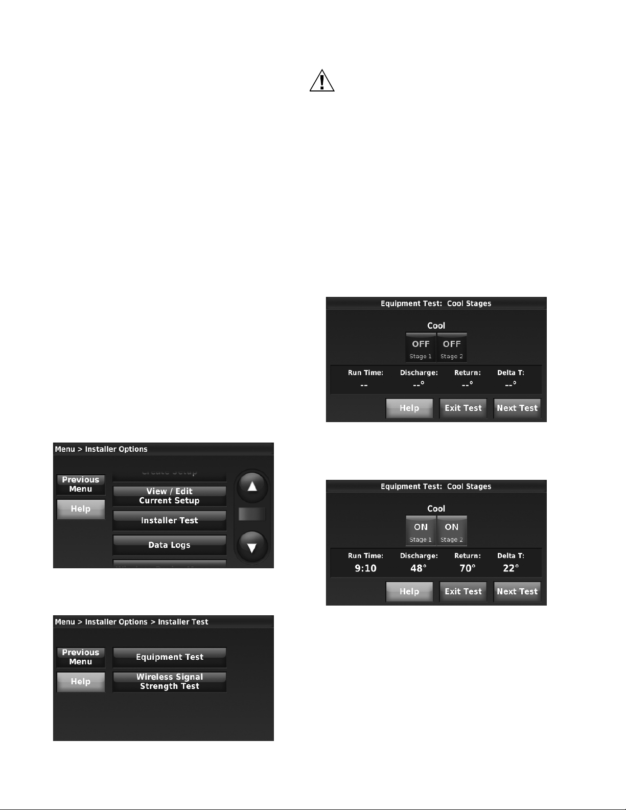
THX9321 PRESTIGE® 2.0 AND THX9421 PRESTIGE® IAQ 2.0 WITH EIM
CAUTION
INSTALLER TESTS
Use the installer tests to check out the system:
• Equipment Test: Tests the heating, cooling, fan, and IAQ
systems. The test allows you to manually call for each
system to ensure the equipment and thermostat operate
properly. Any minimum off timers are ignored during the
system test. You can test the following equipment:
—Heat
—Em Heat
—Cool
—Fan
— Humidification
— Dehumidification
— Ventilation
— Economizer
— Time of Day
• Wireless Signal Strength Test: Run this test to verify that
the thermostat can communicate properly in the installed
location. If not, the thermostat may have to be moved. The
test measures the signal strength between the
— Thermostat and the Equipment Interface Module (in
non-zoned applications)
— Thermostat and the TrueZONE Wireless Adapter (in
zoned applications)
How to Access Installer Tests
1. Press MENU on the home screen, then scroll down to
press Installer Options.
2. Enter the date code (password) when prompted. The
date code is printed on the back of the thermostat or
press MENU > EQUIPMENT STATUS to find the date
code.
3. Press Installer Test.
Equipment Damage Hazard.
Minimum compressor off time is bypassed during
the Equipment Test
Avoid cycling compressor quickly.
How to Use the Equipment Test
1. Press Equipment Test on the Installer Test screen (see
Fig. 41). Turn the equipment on/off as needed and then
press Next Test to test the remaining equipment. The
time out for the Equipment Test mode is 30 minutes (if
there is no keypress for 30 minutes, the thermostat will
automatically exit the Equipment Test).
2. Run Time, Discharge, Return and Delta T data are displayed for heating and cooling tests (requires Discharge
and Return Air Sensors). The Discharge, Return and
Delta T are updated every 30 seconds during the test.
The Run Time counter starts over when the next stage is
turned on.
Fig. 42.
Fig. 40.
4. Select Equipment Test or Wireless Signal Strength Test.
3. Discharge, Return and Delta T are updated every 30
seconds during the equipment test.
Fig. 43.
4. When that equipment test is complete, press Next Test.
5. When system testing is complete, press Exit Test.
Fig. 41.
68-0311—01 48
Page 49

THX9321 PRESTIGE® 2.0 AND THX9421 PRESTIGE® IAQ 2.0 WITH EIM
Press date/time display
Press to select date or time
How to Use the Wireless Signal Strength Test
1. On the Installer Test screen (see Fig. 41) press Wireless
Signal Strength Test.
Fig. 44.
2. Press Test Signal Strength to begin. After a brief
pause, the thermostat will display test results.
3. A number from 5-10 means communication is good.
Set Date and Time
1. To set the date or time, press the date/time display (see
Fig. 47), then select SET TIME or SET DATE.
Fig. 47.
4. If the screen displays “No Signal,” move the thermostat
to a different location and test again.
Fig. 45.
Fig. 46.
Fig. 48.
2. Press the or buttons until the proper time/date is
displayed, then press DONE to save and exit (or press
CANCEL to exit without changing the time).
Fig. 49.
NOTE: The thermostat will switch to and from Daylight
Saving Time automatically.
49 68-0311—01
Page 50

THX9321 PRESTIGE® 2.0 AND THX9421 PRESTIGE® IAQ 2.0 WITH EIM
Fan settings
1. Press FAN.
Fig. 50.
2. Press any displayed option:
• On: Fan is always on.
• Automatic: Fan runs only when heating or cooling
system is on.
• Circulate: Fan runs randomly, about 35% of the time
(residential only).
• Follow Schedule: Fan controlled by program.
NOTE: In commercial use, the CIRCULATE option is
not available.
NOTE: In commercial use, press AUTOMATIC or ON to
temporarily override the programmed fan
schedule.
System Settings
1. Press SYSTEM.
• Conventional Heat Stage 3 (ISU 2100, 2140)
• Backup Heat Stage 2 for Heat Pumps (ISU 2170)
• Geothermal Radiant Heat (ISU 2030, 2040)
Universal Inputs (S1, S2)
S1 and S2 are universal inputs that can be setup to work with a
sensor or dry contact device in the Installer Setup. Setup
options and compatible sensors are listed below. See wiring
diagrams on page 58 and page 119.
Universal Input Options
Indoor Air Sensor (ISU 5000)
• C7189U1005 (10K)
• C7772A1004 (20K)
• C7772A1012 (20K)
• TR21 (20K)
• TR21-A (10K)
Outdoor Air Sensor (ISU 5000)
• C7089U1006 (10K)
Discharge/Return Air Sensors (ISU 5000)
• C7735A1000 (10k)
• C7770A1006 (20K)
• C7041 (20K)
Occupancy Sensor for Remote Setback (ISU 6000)
• WSK-24
Fig. 51.
2. Press any displayed option
• Heat: Thermostat controls only the heating system.
• Cool: Thermostat controls only the cooling system.
• Automatic: Thermostat selects heating or cooling as
needed.
• Off: Heating and cooling system is off. Fan will still
operate if fan is set to On or Circulate.
• Emergency Heat (only for heat pumps with auxiliary
heat): Thermostat controls Auxiliary Heat.
Compressor is not used.
Universal Outputs (U1, U2, U3)
U1, U2, U3 are universal outputs that can be setup to control
IAQ equipment and a stage of heating or cooling in the Installer
Setup. Setup options are listed below. See “THX9321
Thermostat Wiring Diagrams Using Universal Relays to
Control Heating or Cooling” beginning on page 108 for more
information.
Universal Output Options
THX9421 with Equipment Interface Module (U1, U2, U3):
• Humidification (ISU 8030)
• Dehumidification (ISU 9040)
• Ventilation (ISU 10020)
• Cool Stage 3 (ISU 2080)
• Cool Stage 4 (ISU 2090)
• Geothermal Radiant Heat (ISU 2030, 2040)
THX9321 Thermostat Only (U1, U2)
• Humidification (ISU 8030)
• Dehumidification (ISU 9040)
• Ventilation (ISU 10020)
• Cool Stage 3 (ISU 2080)
• Cool Stage 4 (ISU 2090)
Dry Contact Alerts (ISU 6000)
• Low Voltage Dry Contact Device
NOTE: S1 and S2 terminals are only available on the
Equipment Interface Module (EIM).
ALERTS AND DIAGNOSTICS
The thermostat uses alerts and diagnostics to provide greater
comfort and efficiency. Alerts and diagnostics can notify
customers when maintenance or service is needed, and
display your contact information to make it easy for them to
reach you.
Delta T Diagnostics
If discharge and return air sensors are installed, the thermostat
can track system performance over time. It measures this as
“Delta T.” The thermostat monitors Delta T and displays an
alert on the home screen when the system exceeds the limits
you set.
Delta T Diagnostics tells you if the system is performing above
or below expected standards which would normally go
unnoticed, and may cause unnecessary energy use. It can also
detect and warn about problems early, before heating or
cooling equipment fails.
The thermostat will measure and record Delta T of the system
for each stage you test. This information can be used to set the
proper Delta T fault limits of the system. When the system
operates outside those limits multiple times (see “Advanced
Options for Delta T Diagnostics” beginning on page 53), an
alert is recorded in the log. If configured to do so, the system
will then display an alert to the homeowner, along with your
contact information.
68-0311—01 50
Page 51

THX9321 PRESTIGE® 2.0 AND THX9421 PRESTIGE® IAQ 2.0 WITH EIM
Before You Set Up Delta T Diagnostics
Refer to the information below for tips on installation and setup
of Delta T Diagnostics.
1. Refer to Fig. 5–9 for the placement of the Discharge and
Return Air Sensors.
2. In gas or oil forced air systems, Delta T will continue to
rise for several minutes even after Delta T begins to
stabilize. Be sure the Maximum Delta T Limit is set
higher than the expected stable Delta T. See Fig. 52.
MAXIMUM DELTA T LIMIT
DELTA T
MINIMIUM DELTA T LIMIT
DELTA T BEGINS TO STABILIZE
DELTA T NOT STABLE DELTA T STABLE
NOTE: When the system operates below the Minimum
Limit or above the Maximum Limit multiple
times (Table 3), an alert is recorded in the log. If
configured to do so, the thermostat will display
an alert to the user, along with your contact
information.
7. Delta T Diagnostics is only for non-zoned forced air
systems.
8. The thermostat does not provide Heat or Cool Delta T
Diagnostics when it is set to control an Economizer
module (ISU 2220).
9. The thermostat cannot be setup for Heat Delta T
Diagnostics when the thermostat is used with an external
fossil fuel kit (ISU 2190).
Setting up Alerts and Diagnostics
1. Set up the Return and Discharge Air Sensors by
selecting the check boxes on the screen. These sensors
are used to measure Delta T.
RUN TIME WHEN THERMOSTAT
COMPARES DELTA T TO THE
MINIMUM AND MAXIMUM DELTA T LIMITS
RUN TIME
M31489
Fig. 52.
3. Delta T can be affected by indoor and outdoor conditions
for heat pumps and cooling systems. Consider the total
range of normal performance when setting the Delta T
Limits.
For example, in cooling, you might have a Delta T of 20
°F when the outdoor humidity is 50% and a Delta T of 16
°F when the outdoor humidity is 85%.
You can either set Limits further apart and monitor Delta
T during all indoor and outdoor conditions or set Limits
closer together and turn off diagnostics during certain
indoor and outdoor conditions (see “Advanced Options
for Delta T Diagnostics” beginning on page 53).
For example, you can set limits closer together and then
turn off diagnostics when outdoor temperature is above
90 degrees and outdoor humidity is above 85%.
4. Verify the filter is clean and all the registers are open
before running an equipment test.
5. Select a Run Time when Delta T begins to stabilize
during the equipment test.
6. Set Minimum and Maximum Delta T Limits based on
what you consider to be unacceptable performance from
the heating and cooling equipment.
Fig. 53.
2. Select the terminals that are wired to the Discharge and
Return Air Sensors (terminals S1 and S2 at the EIM).
IMPORTANT
Be sure to select the correct terminals for the discharge and return air sensors. For example, if the
return air sensor is wired to S1, select S1 (see Fig.
54) for the return air sensor.
Fig. 54.
51 68-0311—01
Page 52

THX9321 PRESTIGE® 2.0 AND THX9421 PRESTIGE® IAQ 2.0 WITH EIM
3. Select the Discharge and Return Air Sensor Type (10K).
IMPORTANT
10K sensors must be used for Delta T Diagnostics.
Fig. 55.
4. Turn on the Heat and Cool Delta T Diagnostics. Default
is On.
Fig. 58.
6. When you have completed Installer Setup (see “Installer
Setup” beginning on page 14), you will be asked to finish
setting up Diagnostics.
Fig. 56.
Fig. 57.
5. For Air-to-Air Heat Pumps, press the up/down arrows to
set the maximum time duration of a defrost cycle. Default
is 10 minutes. Delta T is not monitored during a defrost
cycle. Check the heat pump documentation for the
defrost cycle time.
Fig. 59.
7. If you press Set Up Diagnostics, you will enter the
Equipment Test. See “Run a Test for Each Stage”
beginning on page 53.
8. If you press I’ll do it later, you will be reminded to finish
setting up diagnostics the next time you exit installer
setup. You can also finish setting up diagnostics by
following the procedure in “If You Decide to Set Up
Diagnostics Later”.
After Delta T Diagnostics Setup is complete, the thermostat will
detect typical failures such as no heating or no cooling and
performance related issues that are typically caused by a dirty
air filter, blocked registers, loss of refrigerant, dirty a-coil,
frozen a-coil, cracked heat exchanger, dirty burners, etc.
If You Decide to Set Up Diagnostics Later
When you are ready to set up diagnostics, follow these steps:
1. From the Home screen, press MENU.
2. Scroll down and press Installer Options.
3. Enter the passcode and press Done (see Note).
NOTE: The passcode is the date code printed on the
back of the thermostat or press
MENU > EQUIPMENT STATUS to find the date
code.
4. Press Set Up Diagnostics.
68-0311—01 52
Page 53

THX9321 PRESTIGE® 2.0 AND THX9421 PRESTIGE® IAQ 2.0 WITH EIM
Fig. 60.
5. Proceed to “Run a Test for Each Stage”.
Run a Test for Each Stage
Follow these steps to run a test for each stage in the HVAC
system.
1. Turn on stage 1.
Set Delta T Limits
1. Press Stage 1 to set the limits and run time (see Fig. 63).
Use the saved test data located in the upper right corner
of the screen to set the Delta T Minimum and Maximum
Limits and the Run Time (see Fig. 64).
Fig. 63.
2. Press the up or down arrows to set the Minimum and
Maximum Limits and the Run Time.
Fig. 61.
2. For each stage you test, wait until Delta T begins to sta-
bilize, then turn on the next stage (if present). See Fig.
62 for an example.
Fig. 62.
3. Press Next Step after Delta T stabilizes for the last stage.
The thermostat saves the Delta T and Run Time Data for
each stage you test and is displayed on the next screen.
NOTE: The thermostat only saves test data for stages
that run 1 minute or longer.
Fig. 64.
3. Set appropriate Minimum and Maximum Delta T Limits
based on the reading from the equipment test and what
you consider to be unacceptable performance from the
heating and cooling equipment.
4. When setting the run time, select a setting based on
when Delta T began to stabilize during the equipment
test. In the example shown in Fig. 62 and 64, Delta T
began to stabilize around 10-11 minutes.
5. Set the limits and run time for all stages of cooling using
steps 1–4 above.
6. Repeat steps 1–5 above for Heating.
After Delta T Diagnostics Setup is Complete
The thermostat will measure Delta T after the specified run
time, and compare Delta T to the minimum and maximum limits
for each valid cycle. If the system operates below the minimum
limit or above the maximum limit multiple times (see Table 3),
an alert is recorded in the Alerts Log. If configured to do so, an
alert is displayed to the user (Display Delta T Alerts to User,
ISU 13190). The user is alerted by default. For example, if 10
of the last 15 cycles have the same fault, an alert is logged and
the user is alerted.
Advanced Options for Delta T Diagnostics
To set Advanced Options for Delta T Diagnostics, select Yes for
ISU 13015.Then the following advanced options are displayed:
• Delta T Alert Sensitivity (ISU 13180; Default: 3)
53 68-0311—01
Page 54

THX9321 PRESTIGE® 2.0 AND THX9421 PRESTIGE® IAQ 2.0 WITH EIM
• Display Delta T Alerts to User (ISU 13190; Default: Yes)
• Allow Delta T Diagnostics:
— during humidification (ISU 13020; Default: Yes)
— during dehumidification (ISU 13030; Default: Yes*)
— during ventilation (ISU 13040; Default: Yes)
— only when indoor temperature is within a certain range
(ISUs 13050, 13090, 13130; Default: Always)
— only when indoor humidity is within a certain range
(ISUs 13060,13100, 13140; Default: Always)
— only when outdoor temperature is within a certain range
(ISUs 13070, 13110, 13150; Default: Always)
— only when outdoor humidity is within a certain range
(ISUs 13080, 13120, 13160; Default: Always)
* Default is Yes for Dehumidifiers and A/C with High Speed
Fan. The thermostat does NOT allow Delta T diagnostics during dehumidification if it is setup for A/C with Low Speed Fan,
Hot Gas Bypass, or Reheat.
The Delta T Alert Sensitivity is set on a scale of 1–5 in ISU
13180 (1 is the least sensitive; 5 is the most sensitive):
Table 3. Delta T Alert Sensitivity (ISU 13180).
Setting Alert is logged and user is alerted if
1 10 of the last 15 valid cycles have the same fault, or
2 10 of the last 15 valid cycles have the same fault, or
3
(Default)
4 5 of the last 5 valid cycles have the same fault, or
5 3 of the last 5 valid cycles have the same fault, or
25 of the last 30 valid cycles have the same fault.
20 of the last 30 valid cycles have the same fault.
5 of the last 5 valid cycles have the same fault, or
10 of the last 15 valid cycles have the same fault, or
15 of the last 30 valid cycles have the same fault.
8 of the last 15 valid cycles have the same fault, or
15 of the last 30 valid cycles have the same fault.
8 of the last 15 valid cycles have the same fault, or
10 of the last 30 valid cycles have the same fault.
Delta T Alerts are displayed for basic failures including no
heating or no cooling that may be related to bad igniter, bad
flame sensor, bad gas valve, bad draft motor, bad blower, bad
contactor, bad startup capacitor, dead compressor, etc.
Delta T Alerts are also displayed for performance related
issues such as dirty air filter, blocked registers, loss of
refrigerant, dirty a-coil, frozen a-coil, cracked heat exchanger,
dirty burners, burners need adjustment, etc.
Alerts are displayed to the user on the home screen. See Fig.
65 for an example.
Fig. 65.
When the user presses the alert for more information, the
Notification screen is displayed, prompting them to perform
some basic troubleshooting and, if the problem persists,
contact their dealer. See Fig. 66 as an example.
By default, Delta T alerts are displayed to the user, but can be
turned off and on in ISU 13190.
Delta T Alerts
The thermostat uses alerts and diagnostics to provide greater
comfort and efficiency. Alerts and diagnostics can notify
customers when maintenance or service is needed, and
display your contact information to make it easy for them to
reach you.
This tells you if the system is performing above or below
expected standards which would normally go unnoticed, and
may cause unnecessary energy use. It can also detect and
warn about problems early, before heating or cooling
equipment fails.
There are three alerts each for the heating and cooling system.
They occur when:
• the system is not operating
NOTE: The thermostat displays an alert when the sys-
tem does not reach a Delta T of 5 F after the
thermostat calls for a reasonable period of time.
• the system is operating below the minimum Delta T limit
• the system is operating above the maximum Delta T limit
Fig. 66.
Alerts are also recorded in the Alerts Log. See “Data Logs”
beginning on page 55.
Delta T Alerts and Utility Saver Switches
For systems that might be interrupted by a utility saver switch
(conventional cooling and heat pumps in the heat and cool
mode), the thermostat will ask if a utility saver switch is
installed and provide an option to the user to turn off
diagnostics temporarily while power is interrupted by the utility
company. Diagnostics can be turned off for 1-14 days.
68-0311—01 54
Page 55
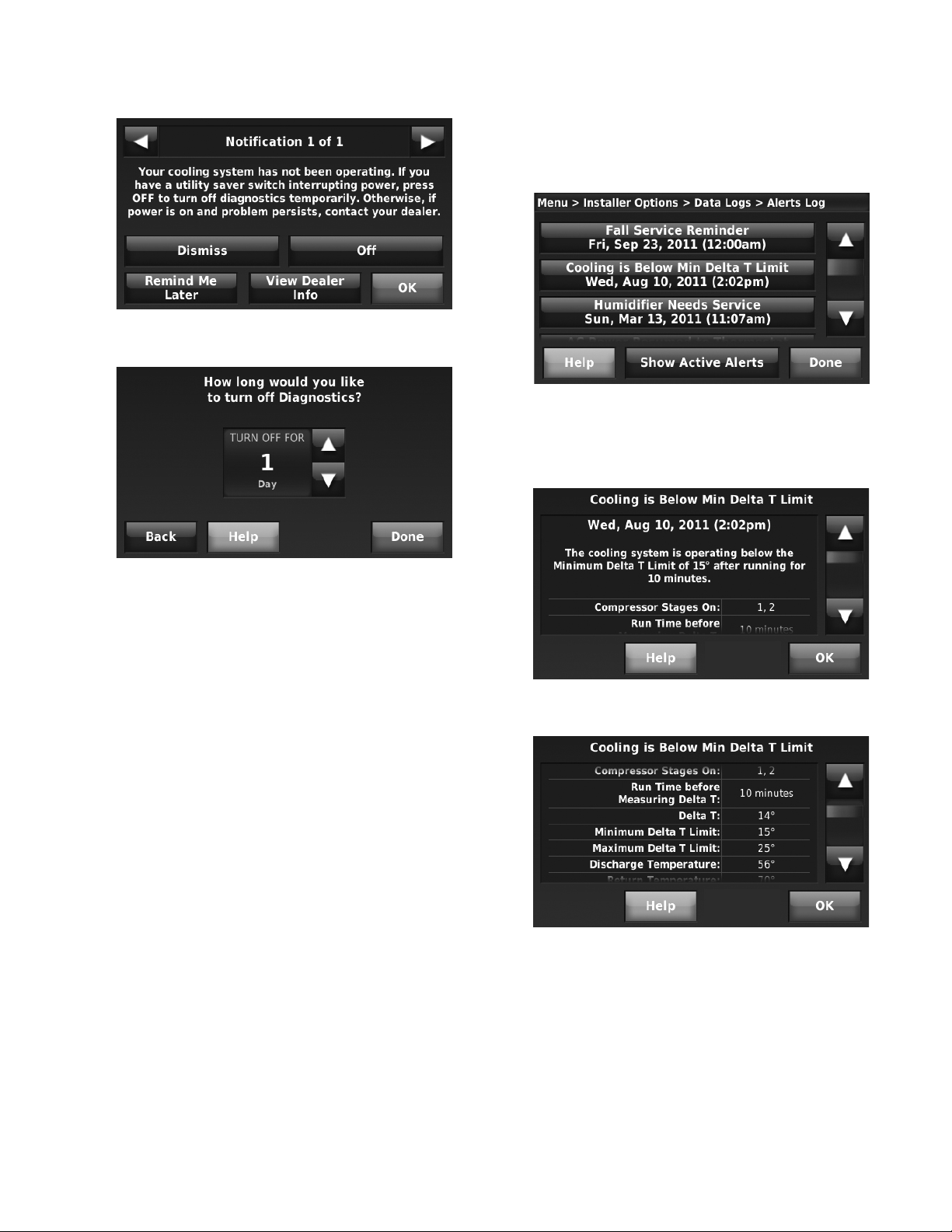
Fig. 67.
THX9321 PRESTIGE® 2.0 AND THX9421 PRESTIGE® IAQ 2.0 WITH EIM
You can also press Show Active Alerts to display the active
alerts that are currently snoozed by the user. This allows the
service technician to dismiss alerts for problems that have
been corrected, and prevent unnecessary callbacks.
Fig. 69.
The Alerts Log contains information about the alert and system
information. See Fig. 70–75 as an example.
Fig. 68.
Data Logs
The Data Logs collect system information that can help point a
service technician in the right direction when troubleshooting.
When accessing the Data Logs, the installer can turn off each
log, delete current log entries, and save Data Logs to a
memory stick via the USB port. See “Using the Data Logs”
beginning on page 56 and “To save a Data Log to a memory
stick” beginning on page 57 for more information.
Data Logs include the Alerts Log and the User Interactions
Log.
Alerts Log
The Alerts Log stores a history of the most recent 25 alerts and
records the date and time of each alert. In the Alerts Log, press
any of the alerts for more information.
Fig. 70.
Fig. 71.
55 68-0311—01
Page 56

THX9321 PRESTIGE® 2.0 AND THX9421 PRESTIGE® IAQ 2.0 WITH EIM
• The alert status (snoozed, dismissed, recovered)
User Interactions Log
The User Interactions Log can help a service technician save
time by determining if the issue is related to a system problem
or an accidental user error.
The User Interactions Log records the date and time for most
changes made by the user, whether made at the thermostat or
from a remote location (RedLINK Internet Gateway, Portable
Comfort Control, etc.). The log saves the most recent 250 user
changes, including:
• Indoor Air Quality Settings
Fig. 72.
• Maintenance Reminders
• Temperature Settings
• System/Fan Mode
• Alerts (snoozed or dismissed)
• Installer Setup
• Date/Time
Using the Data Logs
TO ACCESS THE DATA LOGS
1. From the Home screen, press Menu.
2. Scroll down and press Installer Options.
3. Enter the passcode and press Done.
4. Press Data Logs.
5. Press the log you want to view.
Fig. 73.
Fig. 74.
Fig. 76.
SEARCHING THE USER INTERACTIONS LOG
You can search the User Interactions Log for changes made by
the user.
1. Follow the steps in “Using the Data Logs” beginning on
page 56. Press User Interactions Log.
Fig. 75.
The Alerts Log can include:
• The alert name and description.
• System details at the time of the alert (Delta T, thermostat
settings, heat/cool stages on, status of IAQ equipment, etc.)
• The alert message that is displayed to the user.
68-0311—01 56
Fig. 77.
2. Press Previous Day or Next Day to view user interactions
by date.
Page 57
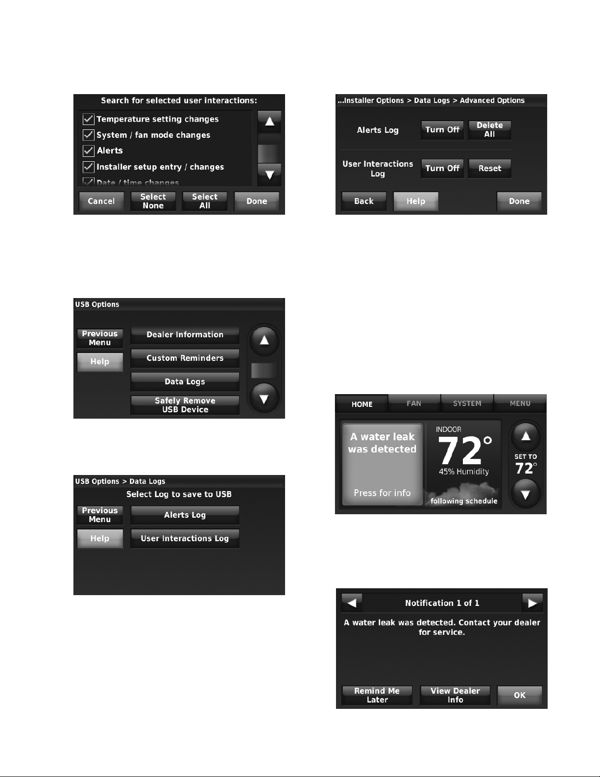
THX9321 PRESTIGE® 2.0 AND THX9421 PRESTIGE® IAQ 2.0 WITH EIM
3. Press Search by Event to search for specific user interactions.
Fig. 78.
4. Select the desired user interactions and press Done.
TO SAVE A DATA LOG TO A MEMORY STICK
1. Insert memory stick in thermostat USB port.
2. The USB options will be displayed.
1. Follow the steps in “Using the Data Logs” beginning on
page 56. Press the Advanced Options button.
Fig. 81.
2. Change the settings and press Done.
Dry Contact Alerts
If you are not using S1 and S2 terminals on the EIM for Delta T
Diagnostics, you can connect them to a dry contact device to
display an alert.
NOTE: You can connect multiple Dry Contact devices in
parallel to the S1 or S2 terminals.
When the dry contact device detects a problem, the thermostat
displays an alert on the home screen along with the dealer
information. See Fig. 82 as an example.
Fig. 79.
3. Press Data Logs.
4. Select the log you want to save to USB.
Fig. 80.
5. When you plug the memory stick into a computer, you
can view Data Log information in a spreadsheet.
ADVANCED DATA LOG OPTIONS
You can turn the Data Logs off or Delete/Reset them from this
screen.
Fig. 82.
When the user presses the alert for more info, the Notification
screen is displayed, prompting them to contact their dealer.
See Fig. 83 as an example.
Fig. 83.
57 68-0311—01
Page 58
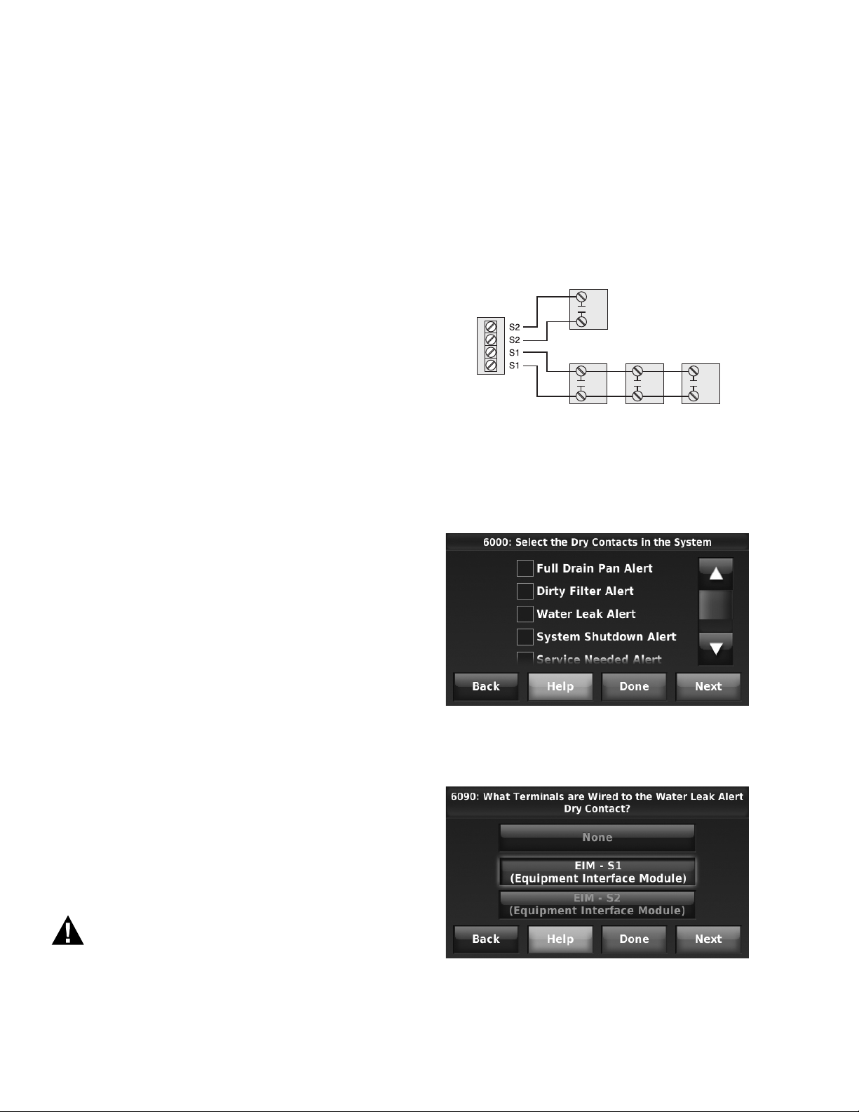
THX9321 PRESTIGE® 2.0 AND THX9421 PRESTIGE® IAQ 2.0 WITH EIM
WARNING
MULTIPLE DRY CONTACT DEVICES
ON ONE SET OF TERMINALS
EIM
M31488
ONE DRY CONTACT DEVICE
The following dry contact alerts are available.
Full Drain Pan Alert
When the dry contact device detects that the condensate drain
pan is full, the thermostat provides an alert to the user.
NOTE: If you want the compressor to turn off when the
drain pan is full, wire the system so the dry contact device turns off the compressor when the
drain pan is full.
Dirty Filter Alert
When the dry contact device detects a dirty air filter (pressure
drop across the filter), the thermostat provides an alert to the
user to replace the filter.
Water Leak Alert
When the dry contact device detects a water leak, the
thermostat provides an alert to the user.
System Shutdown Alert
When the dry contact device detects a critical problem with the
system, the thermostat provides an alert to the user indicating
that the system was shut down.
When the dry contact device detects a problem with the
system (for example, smoke detection), the thermostat will not
call for heating, cooling, fan or IAQ equipment until the dry
contact is deactivated or the feature is unconfigured at the
thermostat.
1. Wire the dry contact device to S1 or S2 terminals at the
EIM.
NOTE: You can connect multiple Dry Contact devices in
parallel to the S1 or S2 terminals. For example,
you can have a variety of dry contact devices connected to the S1 terminals and if any one of them
is triggered, the thermostat will display an alert on
the home screen. You may want to use the Dry
Contact “Custom Alert” when using multiple Dry
Contact devices on one set of terminals.
Fig. 84. Wiring two dry contact devices.
2. Enter Installer Setup (see “Installer Setup” beginning on
page 14).
3. Dry Contacts are selected at ISU 6000. Select the appropriate Dry Contact(s) and press Next.
Service Needed Alert
When the dry contact device detects an issue that requires
service, the thermostat provides an alert to the user.
Fan Failure Alert
The Fan Failure Alert protects the equipment when there is no
airflow. When the dry contact device (for example, sail switch)
detects no air flow for 5 minutes after a call for forced air heat,
cool, or fan, the thermostat provides an alert to the user
indicating that the system was shut down due to a lack of
airflow.
The thermostat will call for the fan and lockout all other
equipment until the dry contact device senses air flow again or
the feature is unconfigured at the thermostat.
Custom Alert
Allows the dealer to enter a custom alert to be displayed when
a dry contact device is activated. For example, a float switch
can detect when your sump pump is not working.
Set Up the Dry Contact Alerts
Equipment Damage Hazard.
Do not apply power to S1 or S2 terminals.
IMPORTANT
The dry contact device must be rated for low voltage.
Fig. 85.
4. Select the terminals wired to the Dry Contact device, and
press Next.
Fig. 86.
5. Select Normally Open or Normally Closed, and press
Next.
68-0311—01 58
Page 59
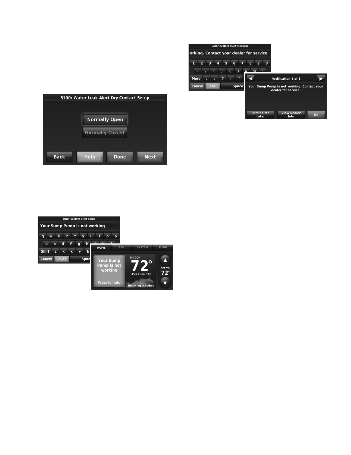
THX9321 PRESTIGE® 2.0 AND THX9421 PRESTIGE® IAQ 2.0 WITH EIM
Home screen
Installer setup
screen
User notification screen
Installer setup
screen
NOTE: For example, if a water leak sensor is normally
open, it will close when the device detects
water. If the water leak sensor is normally
closed, it will open when the device detects
water.
Refer to the instructions packed with the dry
contact device to determine if it is normally
open or normally closed.
Fig. 87.
6. If you are creating a custom alert, type the alert name
into the text box and press Done. The alert name is what
appears on the Home screen when the alert is detected.
See Fig. 88. You can edit or confirm the alert name after
you enter it.
Fig. 89.
8. Repeat steps 4–5 for the other Dry Contact, if necessary.
Staging Control
Differential Between All Stages
The thermostat provides Differential settings between all
stages. The equipment changes stages based on how far the
indoor temperature is from the setpoint. Differential settings
provide a way to balance comfort and conservation.
Heat Differential
The indoor temperature must drop to the selected differential
setting before the thermostat will turn on the stage of heating.
For example, if stage 2 is set to 2 °F (1.0 °C), the indoor
temperature must be 2 °F (1.0 °C) away from the setpoint
before stage 2 turns on. When set to Comfort, the thermostat
will use the stage of heating as needed to keep the indoor
temperature within 1 °F (0.5 °C) degree of the setpoint. The
thermostat turns on stage 2 when the capacity on stage 1
reaches 90%.
Fig. 88.
7. Type the custom alert message into the text box and
press Done. The custom alert message appears when
the orange alert button is pressed. See Fig. 89. You can
edit or confirm the alert message after you enter it.
Cool Differential
The indoor temperature must rise to the selected differential
setting before the thermostat turns on the stage of cooling. For
example, if stage 2 is set to 2 °F (1.0 °C), the indoor
temperature must be 2 °F (1.0 °C) away from the setpoint
before stage 2 turns on. When set to Comfort, the thermostat
uses the stage cooling as needed to keep the indoor
temperature within 1 °F (0.5 °C) degree of the setpoint. The
thermostat turns on stage 2 (or the next stage) when the
capacity on stage 1 reaches 90%.
59 68-0311—01
Page 60

THX9321 PRESTIGE® 2.0 AND THX9421 PRESTIGE® IAQ 2.0 WITH EIM
TO CHANGE DIFFERENTIAL SETTINGS
1. Select Advanced Options to view/adjust differentials
between all stages.
Fig. 90.
2. Default is Comfort. Adjust differentials as needed.
When the Backup Heat Differential is set to 2 °F or higher,
backup heat is not used unless the indoor temperature drops
to the Backup Heat Differential setting or the Backup Heat
Upstage Timer expires, whichever occurs first. The upstage
timer starts when the highest stage of the previous equipment
type turns on.
MANUAL TEMPERATURE CHANGE
When the Backup Heat Differential is set to Comfort, the
thermostat uses backup heat as needed to keep the indoor
temperature within 1 °F (0.5 °C) of the setpoint.
When the Backup Heat Differential is set to 2 °F or higher, if the
primary heat is making progress as expected, backup heat will
not be used to reach the new setpoint. Set to a higher number
to use less backup heat (a greater difference between the
current indoor temperature and the new setpoint is required to
turn on backup heat). See notes below.
PROGRAMMED RECOVERY
If the primary heat is making progress as expected, backup
heat will not be used to reach the setpoint of the next program
period. Backup heat is always restricted during a programmed
recovery when the Adaptive Intelligent Recovery feature is
used. See note below.
NOTE: During a programmed recovery (or when the tem-
perature setpoint is changed by the user), the
thermostat waits to turn on the backup heat
depending on system performance, load conditions and how many degrees the temperature setpoint is changed. Backup heat will be used ONLY
when the temperature is not rising quickly
enough to reach the setpoint in a reasonable time.
Fig. 91.
Backup Heat Differential (Droop)
A Backup Heat Differential is available for any system with 2
heating types. For example:
• Heat Pumps with any type of Backup Heat
• Radiant Heat with any type of Backup Heat
• Hot Water Fan Coil with any type of Backup Heat
The Backup Heat Differential restricts backup heat during the
following conditions:
• Normal Operation
• Manual Setpoint Changes
The options are:
• Comfort – keeps temperature within 1 degree of the
setpoint.
• 2 to 15 °F – Backup heat is not used unless the indoor
temperature drops to the selected Backup Heat Differential.
For example, if the Backup Heat differential is set to 2 °F
(1.0 °C), the indoor temperature must be 2 °F (1.0 °C) away
from the setpoint before the backup heat turns on.
NORMAL OPERATION
When the Backup Heat Differential is set to Comfort, the
thermostat uses backup heat as needed to keep the indoor
temperature within 1 °F (0.5 °C) of the setpoint.
NOTE: If the backup heat was used in the last 2 hours
because the primary heat was not able to maintain the setpoint, the thermostat may turn on the
backup heat earlier when the user raises the setpoint.
TO CHANGE BACKUP HEAT DIFFERENTIAL (DROOP)
SETTINGS
1. Select Advanced Options or Basic Options to view/adjust
Backup Heat Differential settings.
Fig. 92.
2. Default is Comfort. Adjust differentials as needed.
68-0311—01 60
Page 61

THX9321 PRESTIGE® 2.0 AND THX9421 PRESTIGE® IAQ 2.0 WITH EIM
Fig. 93.
Backup Heat Upstage Timer
The Backup Heat Upstage Timer is available for any system
with 2 heating types and the Backup Heat Differential is set to 2
°F (1.0 °C) or higher.
Multistage Control
Multistage Control keeps the high stage of the equipment
running until the desired setpoint is reached. This setting is
recommended for Geothermal Heat Pumps to allow the loop to
rest.
Select Yes to turn on this feature. Default is No.
Backup heat is not used unless the indoor temperature drops
to the Backup Heat Differential setting or the Backup Heat
Upstage Timer expires, whichever occurs first. The upstage
timer starts when the highest stage of the previous equipment
type turns on.
Backup Heat Upstage Timer options are Off, 30 minutes to 16
hours. Default is Off.
Fig. 94.
Fig. 95.
Fig. 96.
61 68-0311—01
Page 62
THX9321 PRESTIGE® 2.0 AND THX9421 PRESTIGE® IAQ 2.0 WITH EIM
Heat pump only
Heat pump with backup heat as needed *
Backup heat only
Heat pump only
Heat pump or backup heat operates *
Backup heat only
Outdoor temperatureOutdoor temperature
Backup heat lockout
Backup heat lockout
Compressor lockout
Compressor lockout
* No backup heat unless indoor temperature drops to selected Backup Heat Differential setting, or Backup Heat
Upstage Timer expires. Heat pump stays ON when backup heat turns on.
* No backup heat unless indoor temperature drops to selected Backup Heat Differential setting, or Backup
Heat Upstage Timer expires. Heat pump turns OFF when backup heat turns on.
Backup heat allowed to run with heat pump (see table below)
Backup heat NOT allowed to run with heat pump (see table below)
HEAT PUMP AND BACKUP HEAT OPERATION
Heat pump with outdoor temperature lockouts
Outdoor temperature lockouts are optional. See Installer Setup options (ISU 3120).
Table 4. Heat Pump and Backup Heat Operation.
Backup Heat Type Backup Heat Operation Backup Heat Fan Operation
Electric forced air Allowed to run with heat pump Thermostat controls fan
Gas or oil forced air NOT allowed to run with heat pump Equipment controls fan
Hot water radiant heat Allowed to run with heat pump [n/a]
Hot water fan coil Selectable in installer setup Thermostat controls fan
Other Selectable in installer setup Selectable in installer setup
Geothermal Radiant Heat
The thermostat can be setup to control Geothermal Radiant
Heat, Geothermal Forced Air Heat and Backup Heat, all from
one thermostat. The thermostat stages the equipment starting
with the Geothermal Radiant Heat followed by Geothermal
Forced Air Heat and then Backup Heat as needed to maintain
the desired temperature. The thermostat allows you to set
differential temperature settings between each stage if you
want the equipment to stage a certain way (see ISU 3030 to
ISU 3090, page 22). For additional wiring diagrams, see
page 107.
NOTE: To turn off Radiant Heat during the shoulder sea-
68-0311—01 62
sons, install an outdoor reset control and connect
to the Radiant Heat or switch the thermostat to
Emergency Heat mode.
Electric Backup Heat (Backup Heat Allowed
to Run with Heat Pump)
HEAT MODE
The thermostat turns on Backup Heat only when the indoor
temperature drops to the selected Backup Heat Differential
setting or the Backup Heat Upstage Timer expires (whichever
occurs first). Geothermal Radiant Heat and Geothermal Forced
Air Heat stay on when the Backup Heat turns on.
EMERGENCY HEAT MODE
The thermostat turns on the Backup Heat to maintain the
desired temperature setting. Geothermal Radiant Heat and
Geothermal Forced Air Heat are not used.
Page 63
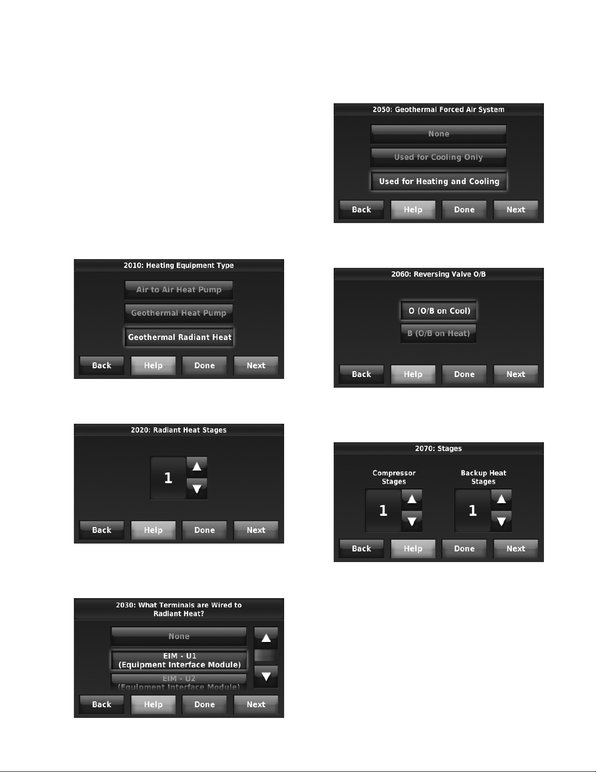
THX9321 PRESTIGE® 2.0 AND THX9421 PRESTIGE® IAQ 2.0 WITH EIM
Fossil Fuel Backup Heat (Backup Heat NOT
Allowed to Run with Heat Pump)
HEAT MODE
The thermostat turns on Backup Heat only when the indoor
temperature drops to the selected Backup Heat Differential
setting or the Backup Heat Upstage Timer expires (whichever
occurs first). Geothermal Forced Air Heat turns off when the
Backup Heat turns on. Geothermal Radiant Heat stays on
when the Backup Heat turns on.
EM. HEAT MODE
The thermostat turns on the Backup Heat to maintain the
desired temperature setting. Geothermal Radiant Heat and
Geothermal Forced Air Heat are not used.
Set Up Geothermal Radiant Heat
1. Select Geothermal Radiant Heat as shown in Fig. 97.
4. Select the Geothermal Radiant Heat Options. For exam-
ple: If this zone is Geothermal Radiant Heat only – select
None. See Fig. 100.
Fig. 100.
5. Select the Reversing Valve. See Fig. 101.
Fig. 97.
2. Select the number of Radiant Heat Stages. See Fig. 98.
Fig. 98.
3. Select the universal terminals wired to the Geothermal
Radiant Heat. See Fig. 99.
Fig. 101.
6. Select the number of Compressor and Backup Heat
Stages. See Fig. 102.
Fig. 102.
7. Select the Backup Heat Type. See Fig. 103.
Fig. 99.
63 68-0311—01
Page 64

THX9321 PRESTIGE® 2.0 AND THX9421 PRESTIGE® IAQ 2.0 WITH EIM
allowing the humidity to go above the Window Limit when it is
controlling the humidifier. This helps inform the user as to why
their humidity setting might not be reached at times.The
Window Limit is based on the current outdoor temperature and
the user's window protection setting.
Fig. 103.
INDOOR AIR QUALITY (IAQ) CONTROL
Humidification
The thermostat reads the indoor humidity level and allows the
user to set a humidification setting with or without window
protection.
The thermostat can be set up to control a humidifier in any
system mode in the Installer Setup (ISU 8060). A discharge air
sensor is required to humidify in the cool mode.
If humidification and dehumidification are setup to operate in
the same system mode (Heat, Cool, Off) and you are sensing
humidity from one location, the thermostat will automatically
enforce a 15% deadband between the humidification and
dehumidification settings. The thermostat will automatically
switch between humidification and dehumidification to maintain
the desired humidity level.
If humidification and dehumidification are setup to operate in
the same system mode (Heat, Cool, Off) and you are sensing
humidity from two different locations using a remote wireless
indoor sensor, the thermostat will allow humidification and
dehumidification to operate at the same time, and there is no
deadband between humidification and dehumidification
settings.
Window Protection
Window Protection limits the amount of humidity to prevent
frost or condensation on windows. Window Protection (ISU
8050) requires an outdoor sensor.
Fig. 104.
If Window Protection is turned Off, the thermostat controls the
humidity level to the user's desired humidity setting. Frost or
condensation may appear on windows.
Set up Humidification
1. Select the Humidifier Type at ISU 8000. See Fig. 105.
NOTE: Based on the humidifier type you select, the
thermostat defaults to the most commonly used
settings for that humidifier type.
For example, a Bypass or Fan Powered humidifier will default ISU 8070 to “Humidify Only
when Fan is On.”
A Steam humidifier will default ISU 8070 to
“Humidify on Demand: Thermostat Controls
Fan.”
The maximum humidity level that is allowed (“Window Limit”) is
displayed on the Humidification Settings screen. The
thermostat prevents frost or condensation on windows by not
68-0311—01 64
Fig. 105.
Page 65

THX9321 PRESTIGE® 2.0 AND THX9421 PRESTIGE® IAQ 2.0 WITH EIM
2. If optional remote wireless indoor sensors are installed,
you can choose which sensor you want to use for humidification control. You can use a different sensor for dehumidification. See “Wireless Indoor Sensor” beginning on
page 96 for more information.
Fig. 106.
3. Select the terminals wired to the humidifier. See Fig.
107.
NOTE: U1, U2, and U3 are Normally Open Dry Con-
tacts that require power from the system transformer or a separate transformer. See “Wiring
guide — IAQ Equipment (EIM or Thermostat)”
beginning on page 115.
5. Select the system mode(s) to allow humidification. See
Fig. 109.
NOTE: Heat includes Heat, Emergency Heat and Auto.
If the system is in Auto mode, the thermostat
will allow humidification if the last call was for
heat.
Cool includes Cool and Auto. If the system is in
Auto mode, the thermostat will allow humidification if the last call was for cool.
Fig. 109.
6. Select from one of the Humidification Control Options
(ISU 8070). See Fig. 110.
• Humidify Only when Heat is On
The thermostat turns on the humidifier only if the heat
is currently running and humidification is needed.
• Humidify Only when Fan is On
The thermostat turns on the humidifier only if the fan
is currently running and humidification is needed.
• Humidify on Demand: Thermostat Controls Fan
The thermostat turns on the humidifier and the fan
when humidification is needed.
• Humidify on Demand: Humidifier Controls Fan
The thermostat turns on the humidifier when
humidification is needed and the humidifier controls
the fan.
Fig. 107.
4. Set Window Protection settings. See Fig. 108.
NOTE: Outdoor sensor is required for Window Protec-
tion.
Fig. 108.
Fig. 110.
7. Set the desired lockout option. See Fig. 111.
65 68-0311—01
Page 66
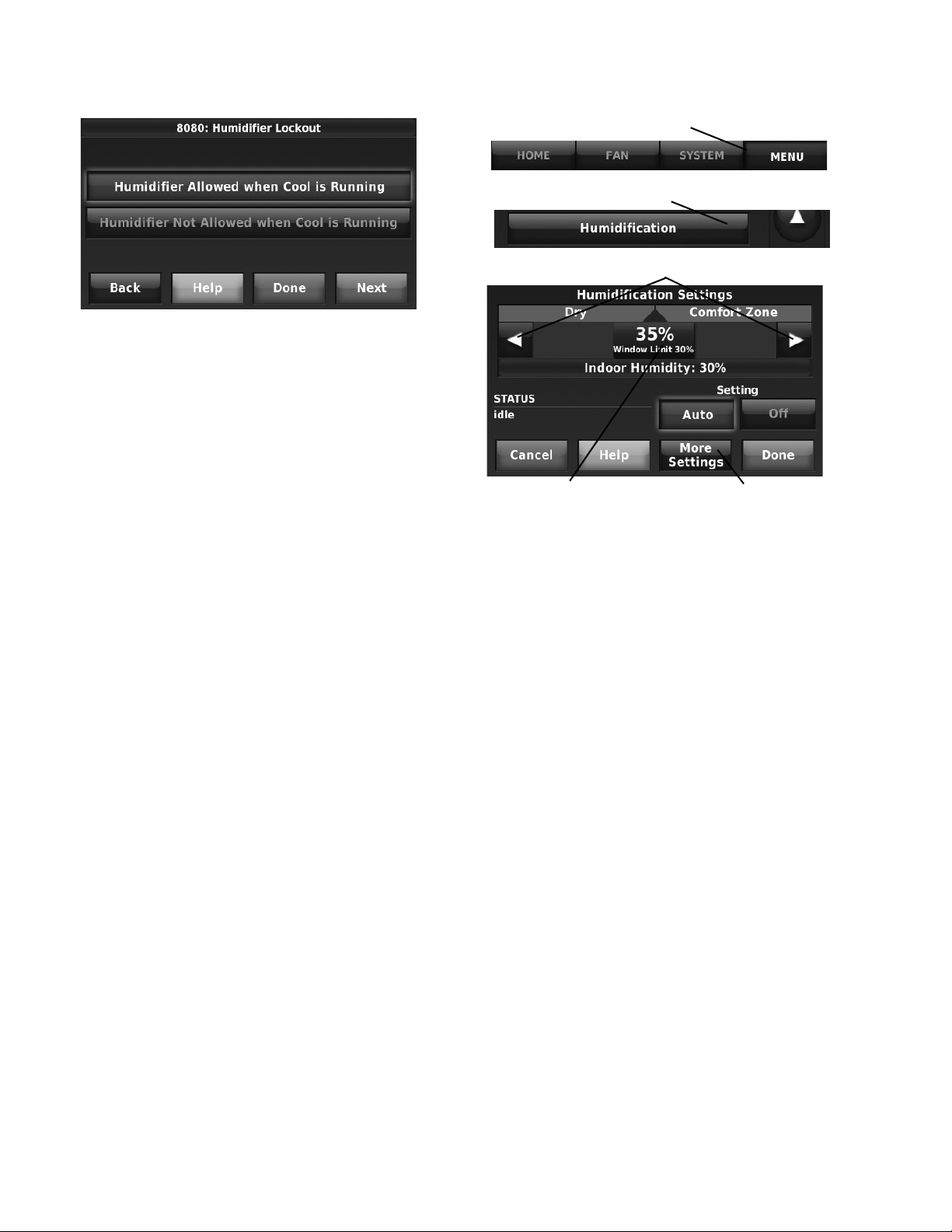
THX9321 PRESTIGE® 2.0 AND THX9421 PRESTIGE® IAQ 2.0 WITH EIM
Press MENU
Scroll to select HUMIDIFICATION
Set humidity to desired level
Window Protection
limits the amount of
humidity to prevent
frost or condensation
on windows
Press More Settings to set:
• Window Protection Setting
• Review humidifier pad or
clean tank / water filter
timer
Fig. 111.
NOTE: ISU 10140 gives the option to lockout ventila-
tion during calls for humidification. This helps
maintain the desired humidity level.
Control Humidification Level
1. Press MENU, then scroll to select Humidification.
2. Press Auto to use the humidifier to maintain your desired
humidity level.
3. Press Off to turn off the humidifier.
4. Move the slider bar to the humidity level you prefer, then
press DONE. The humidification setting range is
10–60% in 5% increments.
5. Press MORE SETTINGS if frost or condensation
appears on windows. A lower number adjusts humidity to
help prevent these problems. Use a higher number if
indoor air is too dry.
NOTE: The Window Protection option is only available if
NOTE: If humidification and dehumidification are setup
an optional outdoor sensor is installed.
to operate in the same system mode (Heat, Cool,
Off) and you are sensing humidity from one location, the thermostat will automatically enforce a
15% deadband between the humidification and
dehumidification settings. The thermostat will
automatically switch between humidification and
dehumidification to maintain the desired humidity
level.
If humidification and dehumidification are setup
to operate in the same system mode (Heat, Cool,
Off) and you are sensing humidity from two different locations using a remote wireless indoor sensor, the thermostat will allow humidification and
dehumidification to operate at the same time, and
there is no deadband between humidification and
dehumidification settings.
Dehumidification - Residential
The thermostat reads the indoor humidity level and allows the
user to set a dehumidification setting. The thermostat controls
the humidity level using the cooling system or a whole house
dehumidifier.
If humidification and dehumidification are setup to operate in
the same system mode (Heat, Cool, Off) and you are sensing
humidity from one location, the thermostat will automatically
enforce a 15% deadband between the humidification and
dehumidification settings. The thermostat will automatically
switch between humidification and dehumidification to maintain
the desired humidity level.
If humidification and dehumidification are setup to operate in
the same system mode (Heat, Cool, Off) and you are sensing
humidity from two different locations using a remote wireless
indoor sensor (for example, main level and crawl space), the
thermostat will allow humidification and dehumidification to
operate at the same time, and there is no deadband between
humidification and dehumidification settings.
Dehumidification using the Cooling System
When set for A/C with Low Speed Fan or A/C with High Speed
Fan, an overcooling limit can be set from 0 °F to 3 °F (ISU
9070). The thermostat uses the cooling system to reduce
humidity by lowering the temperature up to 3° F below the
current cool setpoint until the desired humidity level is reached.
68-0311—01 66
If set for A/C with Low Speed Fan, configure U1, U2, or U3 as
normally open or normally closed (ISU 9050) and wire to the
Low Speed Fan terminal on the equipment. For example, if the
U1, U2, or U3 terminal is normally closed, it will open when the
thermostat calls for dehumidification.See “Wiring guide — IAQ
Equipment (EIM or Thermostat)” beginning on page 115.
Page 67

THX9321 PRESTIGE® 2.0 AND THX9421 PRESTIGE® IAQ 2.0 WITH EIM
NOTE: The thermostat will not lower the fan speed when
the second stage of cooling is on.
Set up Dehumidification With Cooling
System
Some screens shown in this section may not appear on the
thermostat, depending on how you set up dehumidification.
1. Select the Dehumidification Equipment in ISU 9000. See
Fig. 112.
Fig. 112.
2. If optional remote wireless indoor sensors are installed,
you can choose which sensor you want to use for dehumidification control. For example, you can use one sensor for humidification control, and another for
dehumidification. See “Wireless Indoor Sensor” beginning on page 96 for more information.
4. Select the terminals wired to the A/C with Low Speed
Fan. See Fig. 115.
Fig. 115.
5. Select whether the U1, U2, or U3 terminals are Normally
Open or Normally Closed. See Fig. 116.
• Normally Open – contacts are normally open and will
close during a call for dehumidification
• Normally Closed – contacts are normally closed and
will open during a call for dehumidification.
Fig. 113.
3. If you are sensing humidity from two separate locations
(one for humidification and another for dehumidification),
you can select which humidity reading to display on the
home screen. See “Wireless Indoor Sensor” beginning
on page 96 for more information.
Fig. 114.
Fig. 116.
6. Set the Overcooling Limit. See Fig. 117. Options:
• 0 °F to 3 °F (A/C with Low Speed Fan)
• 1 °F to 3 °F (A/C with High Speed Fan)
Fig. 117.
NOTE: ISU 10140 gives the option to lockout ventila-
tion on calls for dehumidification. This helps
maintain the desired humidity level.
Dehumidification using a Whole House
Dehumidifier
The Whole House Dehumidifier option requires a dedicated
unit for dehumidification. The thermostat can be set to control
dehumidification in all modes (Heat, Off, Cool [ISU 9120]).
67 68-0311—01
Page 68

THX9321 PRESTIGE® 2.0 AND THX9421 PRESTIGE® IAQ 2.0 WITH EIM
Set up Dehumidification With Whole House
Dehumidifier
Some screens shown in this section may not appear on the
thermostat, depending on how you set up dehumidification.
1. Select the Dehumidification Equipment in ISU 9000. See
Fig. 118.
Fig. 118.
2. If optional remote wireless indoor sensors are installed,
you can choose which sensor you want to use for dehumidification control. For example, you can use one sensor for humidification control, and another for
dehumidification. See “Wireless Indoor Sensor” beginning on page 96 for more information.
4. Select the terminals wired to the Whole House Dehumidifier. See Fig. 121.
Fig. 121.
5. Select the system mode(s) to allow dehumidification.
See Fig. 122.
NOTE: Heat includes Heat, Emergency Heat and Auto.
If the system is in Auto mode, the thermostat
will allow dehumidification if the last call was for
heat.
Cool includes Cool and Auto. If the system is in
Auto mode, the thermostat will allow dehumidification if the last call was for cool.
Fig. 119.
3. If you are sensing humidity from two separate locations
(one for humidification and another for dehumidification),
you can select which humidity reading to display on the
home screen. See “Wireless Indoor Sensor” beginning
on page 96 for more information.
Fig. 120.
68-0311—01 68
Fig. 122.
6. Set Dehumidifier Fan Control settings. See Fig. 123.
• Thermostat Controls Fan
Thermostat turns on the dehumidifier and the fan
when dehumidification is needed.
• Equipment Controls Fan
Thermostat turns on the dehumidifier when
dehumidification is needed. The fan is controlled by
the equipment.
Fig. 123.
Page 69

THX9321 PRESTIGE® 2.0 AND THX9421 PRESTIGE® IAQ 2.0 WITH EIM
7. Set the desired lockout option. See Fig. 124.
Fig. 124.
NOTE: ISU 10140 gives the option to lockout ventila-
tion during calls for dehumidification. This helps
maintain the desired humidity level.
Dehumidification Away Mode
Dehumidification Away Mode protects the home when
unoccupied for long periods of time during hot and humid
weather by maintaining the desired humidity and temperature
settings.
To start Dehumidification Away Mode, press MENU, then press
Dehumidification Away Mode.
Set up Dehumidification Away Mode
1. Select Allowed at ISU 9180. See Fig. 127.
Fig. 127.
2. Set Fan Control settings. See Fig. 128.
• On: Fan is always on.
• Automatic: Fan runs only when cooling system is on.
• Circulate: Fan runs randomly, about 35% of the time.
Fig. 125.
The thermostat automatically follows settings that are set by
the dealer during installer setup.
Press Cancel to end Dehumidification Away Mode.
Fig. 126.
Fig. 128.
3. Set temperature and dehumidification settings. See Fig.
130.
• Low Limit Temperature Setting
If the cooling system is used to control humidity while
Dehumidification Away Mode is active, the thermostat
allows the cooling system to lower the indoor air to the
Low Limit Temperature Setting to reach the
Dehumidification Setting at ISU 9200.
• Temperature Setting
The temperature maintained while Dehumidification
Away Mode is active and the desired humidity level is
satisfied.
• Dehumidification Setting
The desired humidity level while Dehumidification
Away Mode is active.
Fig. 129.
69 68-0311—01
Page 70
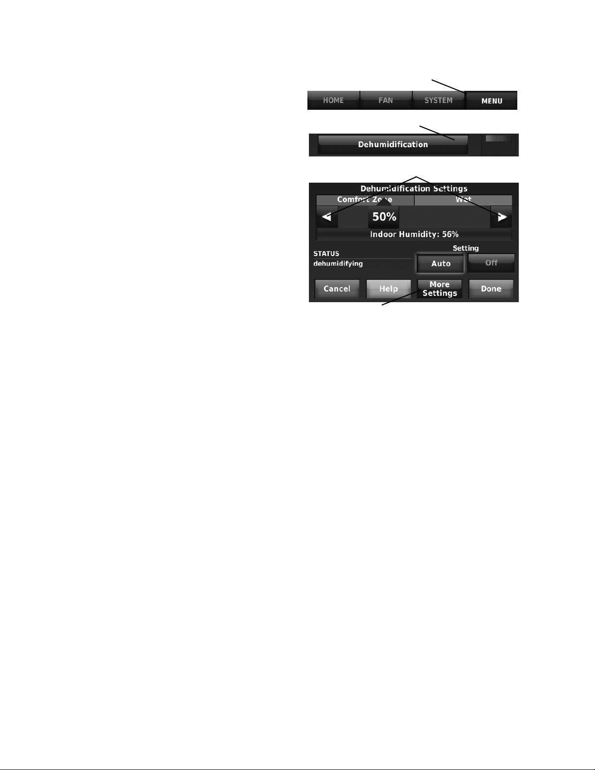
THX9321 PRESTIGE® 2.0 AND THX9421 PRESTIGE® IAQ 2.0 WITH EIM
Press MENU
Scroll to select DEHUMIDIFICATION
Set humidity to desired level
Press to review filter timer
Control Dehumidification Level
1. Press MENU, then scroll to select Dehumidification.
2. Press Auto to use the dehumidifier or cooling system to
maintain your desired humidity level.
3. Press Off to turn off dehumidification.
4. Move the slider bar to the humidity level you prefer, then
press DONE. The dehumidification setting range is
40–80% in 5% increments.
NOTE: When set for A/C with Low Speed Fan or A/C
with High Speed Fan, an overcooling limit can
be set from 0 °F to 3 °F (ISU 9070). The thermostat uses the cooling system to reduce
humidity by lowering the temperature up to 3° F
below the current cool setpoint until the desired
humidity level is reached.
5. Press MORE SETTINGS to review or change settings for
the dehumidifier filter timer.
NOTE: If humidification and dehumidification are setup
to operate in the same system mode (Heat, Cool,
Off) and you are sensing humidity from one location, the thermostat will automatically enforce a
15% deadband between the humidification and
dehumidification settings. The thermostat will
automatically switch between humidification and
dehumidification to maintain the desired humidity
level.
If humidification and dehumidification are setup
to operate in the same system mode (Heat, Cool,
Off) and you are sensing humidity from two different locations using a remote wireless indoor sensor (for example, main level and crawl space), the
thermostat will allow humidification and dehumidification to operate at the same time, and there is
no deadband between humidification and dehumidification settings.
Dehumidification - Commercial
The thermostat reads the indoor humidity level and allows the
user to set a dehumidification setting. The thermostat controls
the humidity level using the cooling system or a dehumidifier.
If humidification and dehumidification are setup to operate in
the same system mode (Heat, Cool, Off) and you are sensing
humidity from one location, the thermostat will automatically
enforce a 15% deadband between the humidification and
dehumidification settings. The thermostat will automatically
switch between humidification and dehumidification to maintain
the desired humidity level.
68-0311—01 70
If humidification and dehumidification are setup to operate in
the same system mode (Heat, Cool, Off) and you are sensing
humidity from two different locations using a remote wireless
indoor sensor (for example, main level and crawl space), the
thermostat will allow humidification and dehumidification to
operate at the same time, and there is no deadband between
humidification and dehumidification settings.
Dehumidification Equipment Options: (ISU 9000)
• A/C with Low Speed Fan
• A/C with High Speed Fan
• Hot Gas Bypass
• Dehumidifier
NOTE: Hot Gas Bypass - During a call for dehumidifica-
tion, the cooling capacity will be used to remove
more latent heat than sensible heat. The operation
of Hot Gas Bypass varies by equipment. For more
details, contact the equipment manufacturer.
Page 71

THX9321 PRESTIGE® 2.0 AND THX9421 PRESTIGE® IAQ 2.0 WITH EIM
Dehumidification using the Cooling System
Dehumidification using A/C with Low Speed Fan, A/C with High
Speed Fan or Hot Gas Bypass, has the following methods of
dehumidification control (ISU 9080):
Fig. 130.
Basic: This option uses the cooling system to reach the
desired humidity level. Minimum On Time, High Humidity
Comfort Reset and Reheat are not used with this method. This
setting is commonly used if your dehumidification equipment is
Hot Gas Bypass.
Minimum On Time (ISU 9090): This option ensures that the
compressor runs long enough to effectively reduce humidity
when the cooling equipment is cycled on. The compressor will
run for the minimum “on time” you set until the desired humidity
level is reached.
Reheat with Minimum On Time (ISU 9080 and 9090): This
method uses both Reheat and Minimum On Time options
above to reach the desired humidity level.
If set for A/C with Low Speed Fan, configure U1, U2, or U3 as
normally open or normally closed (ISU 9050) and wire to the
Low Speed Fan terminal on the equipment. For example, if the
U1, U2, or U3 terminal is normally closed, it will open when the
thermostat calls for dehumidification.See “Wiring guide — IAQ
Equipment (EIM or Thermostat)” beginning on page 115.
NOTE: The thermostat will not lower the fan speed when
the second stage of cooling is on.
Set up Dehumidification With Cooling
System
Some screens shown in this section may not appear on the
thermostat, depending on how you set up dehumidification.
1. Select the Dehumidification Equipment in ISU 9000. See
Fig. 131.
High Humidity Comfort Reset (ISU 9100): This option uses
the cooling system to lower the temperature up to 5° F below
the current cool setpoint until the desired humidity is reached.
The high humidity comfort range is from 1° to 5° F.
High Humidity Comfort Reset with Minimum On Time (ISU
9090 and 9100): This method uses both options above to
reduce humidity while maintaining a comfortable temperature.
Reheat (ISU 9080): This option allows heating to run during
dehumidification to help maintain a comfortable temperature. If
only cooling stage 1 is used, during the “off” cycle, both cooling
and heating run at the same time as needed to dehumidify
without overcooling. This option cannot be used in the Heat
mode. This option is effective only if using a system with the ACoil located before the heating coil (heat exchanger). This
feature requires a conventional forced air heating system (gas,
oil, or electric) in the application.
NOTE: Reheat can be used on heat pump applications
that have a forced air backup heat source (gas,
oil, or electric). The thermostat will turn on the
first stage of forced air backup heat during
Reheat.
NOTE: Reheat can be used on systems where the A-Coil
is located after the heating coil (heat exchanger),
but it is not effective at removing humidity.
Fig. 131.
2. If optional remote wireless indoor sensors are installed,
you can choose which sensor you want to use for dehumidification control. For example, you can use one sensor for humidification control, and another for
dehumidification. See “Wireless Indoor Sensor” beginning on page 96 for more information.
Fig. 132.
71 68-0311—01
Page 72

THX9321 PRESTIGE® 2.0 AND THX9421 PRESTIGE® IAQ 2.0 WITH EIM
3. If you are sensing humidity from two separate locations
(one for humidification and another for dehumidification),
you can select which humidity reading to display on the
home screen. See “Wireless Indoor Sensor” beginning
on page 96 for more information.
Fig. 133.
4. Select the terminals wired to the A/C with Low Speed
Fan or Hot Gas Bypass. See Fig. 134.
6. Set the Dehumidification Control. See Fig. 136. For more
information about these options, see “Dehumidification
using the Cooling System” on page 71.
Fig. 136.
NOTE: ISU 10140 gives the option to lockout ventila-
tion on calls for dehumidification. This helps
maintain the desired humidity level.
Dehumidification using a Dehumidifier
The Dehumidifier option requires a dedicated unit for
dehumidification. The thermostat can be set to control
dehumidification in all modes (Heat, Off, Cool [ISU 9120]).
Set up Dehumidification With Dehumidifier
Some screens shown in this section may not appear on the
thermostat, depending on how you set up dehumidification.
Fig. 134.
5. Select whether the U1, U2, or U3 terminals are Normally
Open or Normally Closed. See Fig. 135.
• Normally Open – contacts are normally open and will
close during a call for dehumidification
• Normally Closed – contacts are normally closed and
will open during a call for dehumidification.
Fig. 135.
1. Select the Dehumidification Equipment in ISU 9000. See
Fig. 137.
Fig. 137.
2. If optional remote wireless indoor sensors are installed,
you can choose which sensor you want to use for dehumidification control. For example, you can use one sen-
68-0311—01 72
Page 73

THX9321 PRESTIGE® 2.0 AND THX9421 PRESTIGE® IAQ 2.0 WITH EIM
sor for humidification control, and another for
dehumidification. See “Wireless Indoor Sensor” beginning on page 96 for more information.
Fig. 138.
3. If you are sensing humidity from two separate locations
(one for humidification and another for dehumidification),
you can select which humidity reading to display on the
home screen. See “Wireless Indoor Sensor” beginning
on page 96 for more information.
Fig. 141.
6. Set Dehumidifier Fan Control settings. See Fig. 142.
• Thermostat Controls Fan
Thermostat turns on the dehumidifier and the fan
when dehumidification is needed.
• Equipment Controls Fan
Thermostat turns on the dehumidifier when
dehumidification is needed. The fan is controlled by
the equipment.
Fig. 139.
4. Select the terminals wired to the Dehumidifier. See Fig.
140.
Fig. 140.
5. Select the system mode(s) to allow dehumidification.
See Fig. 141.
NOTE: Heat includes Heat, Emergency Heat and Auto.
If the system is in Auto mode, the thermostat
will allow dehumidification if the last call was for
heat.
Cool includes Cool and Auto. If the system is in
Auto mode, the thermostat will allow dehumidification if the last call was for cool.
Fig. 142.
7. Set the desired lockout option. See Fig. 143.
Fig. 143.
NOTE: ISU 10140 gives the option to lockout ventila-
tion on calls for dehumidification. This helps
maintain the desired humidity level.
Dehumidification Away Mode
Dehumidification Away Mode for a commercial application is
identical to Dehumidification Away Mode for a residential
application. See “Dehumidification Away Mode” on page 69
and “Set up Dehumidification Away Mode” beginning on
page 69.
73 68-0311—01
Page 74

THX9321 PRESTIGE® 2.0 AND THX9421 PRESTIGE® IAQ 2.0 WITH EIM
Press MENU
Scroll to select DEHUMIDIFICATION
Set humidity to desired level
Press to review filter timer
Control Dehumidification Level
1. Press MENU, then scroll to select Dehumidification.
2. Press Auto to use the dehumidifier or cooling system to
maintain your desired humidity level.
3. Press Off to turn off dehumidification.
4. Move the slider bar to the humidity level you prefer, then
press DONE. The dehumidification setting range is
40–80% in 5% increments.
5. If your air conditioner is used to control humidity, the
thermostat may use the following methods to maintain
your desired humidity:
• Cool from 1° to 5° F lower than your temperature
setting.
• Run cooling for the minimum “on” time to reduce
humidity.
• Run cooling and heating at the same time to reduce
humidity without lowering the temperature.
6. Press MORE SETTINGS to review or change settings for
the dehumidifier filter timer.
NOTE: If humidification and dehumidification are setup
to operate in the same system mode (Heat, Cool,
Off) and you are sensing humidity from one location, the thermostat will automatically enforce a
15% deadband between the humidification and
dehumidification settings. The thermostat will
automatically switch between humidification and
dehumidification to maintain the desired humidity
level.
Ventilation
If humidification and dehumidification are setup
to operate in the same system mode (Heat, Cool,
Off) and you are sensing humidity from two different locations using a remote wireless indoor sensor (for example, main level and crawl space), the
thermostat will allow humidification and dehumidification to operate at the same time, and there is
no deadband between humidification and dehumidification settings.
The thermostat can be set for the following ventilation types:
(ISU 10000)
• ERV/HRV
• Passive (Fan Only)
• Fresh Air Damper
Ventilation Control Methods (ISU 10050)
Ventilation can be setup to meet either ASHRAE or Percent On
Time settings. To meet these settings, the thermostat will
ventilate during calls for heat, cool, and fan. If the required
ventilation has not been achieved for ASHRAE or Percent On
Time, the thermostat will force the ventilation equipment on.
68-0311—01 74
• ASHRAE
The thermostat operates ventilation equipment to meet the
ASHRAE 62.2 ventilation standard based on CFM, number
of bedrooms, and square footage of the house. ASHRAE
62.2 can only be met if the ventilation equipment is running.
If the ventilation equipment is off for any reason (outdoor
ventilation lockouts, set up to turn Off during Sleep period,
turned off by user, etc.), ASHRAE 62.2 is not met during
those times. See ISU 10125 to select a Ventilation Priority.
• Percent On Time
The thermostat operates ventilation equipment based on a
percentage entered in the installer setup (ISU 10120). For
example if Percent On Time is set to 50%, the ventilation
equipment will run at random times during a 1 hour period
until it reaches a 50% run time (approximately 30 minutes).
Default setting is 30%. Range is 10% to 100% in 10%
increments.
Ventilation Fan Control (ISU 10060)
• Thermostat Controls Fan
The thermostat turns on the ventilator and the fan when
ventilation is needed.
Page 75
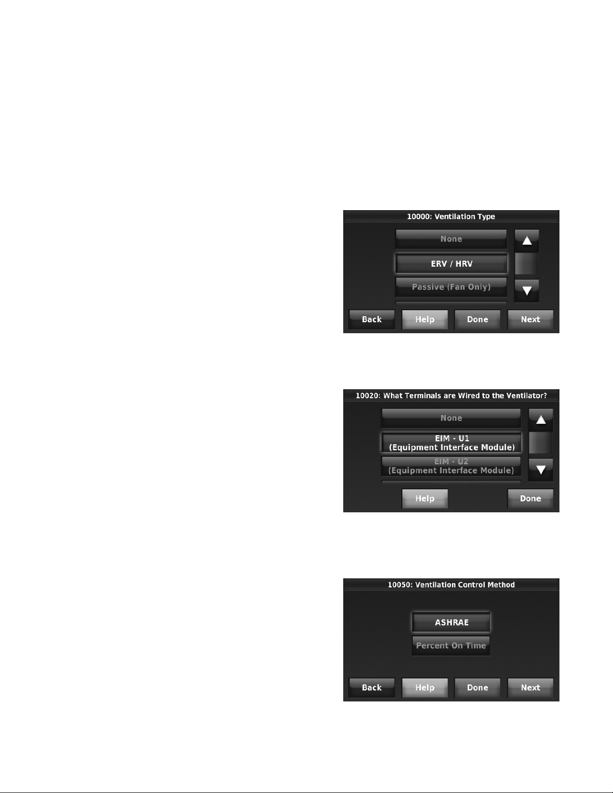
THX9321 PRESTIGE® 2.0 AND THX9421 PRESTIGE® IAQ 2.0 WITH EIM
• Equipment Controls Fan
The thermostat turns on the ventilator when ventilation is
needed. The fan is controlled by the equipment.
Ventilation Priority (ISU 10125)
• Lockouts are Priority
The thermostat places a priority on lockouts versus the
ASHRAE 62.2 ventilation standard. The thermostat will not
run ventilation during the following lockout conditions (if
configured) unless you manually call for ventilation:
— Lockout Ventilation during Outdoor Conditions (ISU
10130)
— Lockout Ventilation on Humidification or Dehumidifica-
tion Calls (ISU 10140)
— Lockout Ventilation during “Sleep” (Residential) or
“Unoccupied” (Commercial) program periods. Note:
This option is set by the user on the Ventilation screen
in the Menu.
• ASHRAE is Priority
ASHRAE requires additional ventilation following a long off
cycle. The thermostat meets the ASHRAE 62.2 ventilation
standard by running additional ventilation when outdoor
conditions are favorable. If ASHRAE cannot be met when
outdoor conditions are favorable, the thermostat will
override the outdoor lockouts and run ventilation. When
using this option, it is recommended to increase the rate
(CFM) of the ventilation equipment to meet the ASHRAE
62.2 ventilation standard in a shorter run time.
Ventilate on High Indoor Humidity (ISU
10160)
If set to ventilate on high indoor humidity, the ventilator turns on
to remove excess humidity if the indoor humidity is 10% above
the Humidification setting. The thermostat must be in the heat
mode to ventilate on high indoor humidity.
Set up Ventilation
Some screens shown in this section may not appear on the
thermostat, depending on how you set up ventilation.
1. Select the Ventilation Type in ISU 10000. See Fig. 144.
Fig. 144.
NOTES: ISU 10140 “Lockout Ventilation on Humidification or
Dehumidification Calls” is not an option when you
select “ASHRAE is Priority”.
The ability to lockout ventilation during the “Sleep” or
“Unoccupied” program periods is not an option when
you select “ASHRAE is Priority”.
Ventilation — Outdoor Condition Lockouts
(ISU 10130)
Ventilation will not operate when outdoor conditions exceed the
lockout settings unless you manually call for ventilation or
Ventilation Priority (ISU 10125) is set to ASHRAE is Priority
and ventilation is needed to meet ASHRAE. Lockouts can
prevent ventilation during extreme weather conditions to keep
humid, hot, and cold air out of the home.
NOTE: This feature requires an outdoor sensor.
If the outdoor sensor also measures humidity, ventilation will
not be allowed when the outdoor dewpoint is above the level
you set. Options are:
• Ventilation Low Temperature Lockout Setpoint
(Off, -20° to 40° F)
• Ventilation High Temperature Lockout Setpoint
(Off, 80° to 110° F)
• Ventilation High Dewpoint Lockout Setpoint
(Off, 65° to 85° F)
2. Select the terminals wired to the Ventilator (or Fresh Air
Damper). See Fig. 145.
Fig. 145.
3. Select the Ventilation Control Method. See “Ventilation
Control Methods (ISU 10050)” on page 74 for more information. See Fig. 146.
Refer to the information below if you need assistance setting
the High Dewpoint Lockout.
• Higher than 80: Extremely uncomfortable
• 75 to 80: Very uncomfortable
• 70 to 74: Quite uncomfortable
• 65 to 69: Somewhat uncomfortable
Fig. 146.
75 68-0311—01
Page 76

THX9321 PRESTIGE® 2.0 AND THX9421 PRESTIGE® IAQ 2.0 WITH EIM
4. Select the Ventilation Fan Control. See “Ventilation Fan
Control (ISU 10060)” on page 74 for more information.
See Fig. 147.
NOTE: ISU 10060 is only displayed if the Ventilation
Type is ERV / HRV. The thermostat controls the
fan if the Ventilation Type is Fresh Air Damper.
Fig. 149.
Fig. 147.
5. If ASHRAE was selected for ISU 10050, select the Num-
ber of Bedrooms and Size of House. See Fig. 148.
Fig. 148.
6. If ASHRAE was selected for ISU 10050, enter the Equip-
ment Ventilation Rate (CFM). Be sure this setting corresponds with the actual ventilator speed. This setting
determines how often the ventilation equipment will operate to meet the ASHRAE 62.2 Standard. The thermostat
will indicate the following based on the Equipment Ventilation Rate, Square Footage and Number of Bedrooms.
See Fig. 149.
• Provides an indication if it meets or does not meet the
ASHRAE 62.2 Standard.
• Provides% run time that is needed to meet the
ASHRAE 62.2 Standard.
7. Select a Ventilation Priority (see Fig. 150):
a. Lockouts are Priority: The thermostat places a pri-
ority on lockouts versus the ASHRAE 62.2 ventilation
standard. The thermostat will not run ventilation during the following lockout conditions (if configured)
unless you manually call for ventilation:
(1) Lockout Ventilation during Outdoor Conditions
(ISU 10130)
(2) Lockout Ventilation on Humidification or Dehu-
midification Calls (ISU 10140)
(3) Lockout Ventilation during “Sleep” (Residential) or
“Unoccupied” (Commercial) program periods.
Note: This option is set by the user on the Ventilation screen in the Menu.
b. ASHRAE is Priority: ASHRAE requires additional
ventilation following a long off cycle. The thermostat
meets the ASHRAE 62.2 ventilation standard by running additional ventilation when outdoor conditions
are favorable. If ASHRAE cannot be met when outdoor conditions are favorable, the thermostat will
override the outdoor lockouts and run ventilation.
When using this option, it is recommended to
increase the rate (CFM) of the ventilation equipment
to meet the ASHRAE 62.2 ventilation standard in a
shorter run time.
NOTE: ISU 10140 “Lockout Ventilation on Humidifica-
tion or Dehumidification Calls” is not an option
when you select “ASHRAE is Priority”.
The ability to lockout ventilation during the
“Sleep” or “Unoccupied” program periods is not
an option when you select “ASHRAE is Priority”.
68-0311—01 76
Page 77
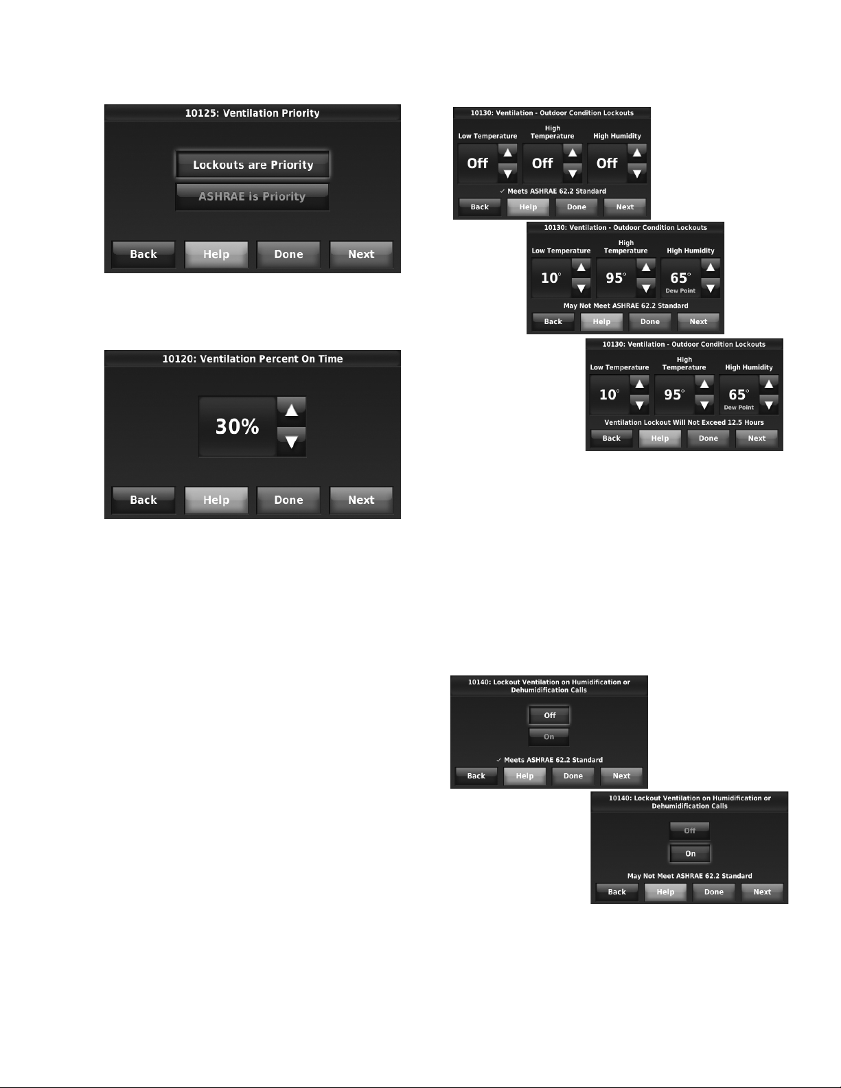
THX9321 PRESTIGE® 2.0 AND THX9421 PRESTIGE® IAQ 2.0 WITH EIM
Fig. 150.
8. If Percent On Time was selected for ISU 10050, select
the Ventilation Percent on Time. See Fig. 151.
Fig. 151.
9. Select the Outdoor Condition Lockouts. See “Ventilation
— Outdoor Condition Lockouts (ISU 10130)” on page 75
for more information.
When ISU 10125 Ventilation Priority is set to Lockouts
are Priority, or ISU 10050 Ventilation Control Methods is
set to Percent On Time, the thermostat will indicate
whether this meets or may not meet the ASHRAE 62.2
Standard or the Percent On Time setting. See Fig. 152.
When ISU 10125 Ventilation Priority is set to ASHRAE is
Priority, the screen below will indicate the maximum
length of time that ventilation can be locked out over a 21
hour time period. For example, Ventilation Lockout Will
Not Exceed 12.5 hours. The length of time that ventilation is locked out is limited to ensure that the ASHRAE
62.2 Ventilation Standard is met. See Fig. 152.
Fig. 152.
10. Select whether to lockout ventilation on humidification or
dehumidification calls. This feature is used to help reach
the user's desired humidity level by not allowing the ventilation equipment to run during a call for humidification
or dehumidification. The thermostat will indicate whether
this meets or may not meet the ASHRAE 62.2 Standard
or the Percent On Time setting. See Fig. 153.
NOTE: ISU 10140 “Lockout Ventilation on Humidifica-
tion or Dehumidification Calls” is not an option
when you select “ASHRAE is Priority” at ISU
10125.
Fig. 153.
77 68-0311—01
Page 78

THX9321 PRESTIGE® 2.0 AND THX9421 PRESTIGE® IAQ 2.0 WITH EIM
Press MENU
Scroll to select VENTILATION
Set operating mode
Press More Settings to:
• Set outdoor lockouts (on or off)
• Turn off ventilation during the Sleep or Unoccupied
program period
• Review ventilator filter and ventilator core timer
Set temporary run time
11. Select whether to Ventilate on High Indoor Humidity. See
“Ventilate on High Indoor Humidity (ISU 10160)” on
page 75 for more information. See Fig. 154.
Fig. 154.
Control Ventilation Level
1. Press MENU, then scroll to select Ventilation.
2. Press Setting to set the operating mode.
• Automatic: Ventilation runs as programmed by the
installer (ASHRAE or Percent On Time).
• Off: Ventilation remains off unless turned on by the
timer or from a Vent Boost Remote.
• On: Ventilation is always on.
3. Press or to run ventilation temporarily. The Tempo-
rary Boost (timer) setting range is 0–180 in 20 minute
increments. To turn Temporary Boost off, set to zero or
press Cancel Temporary Boost.
4. Press MORE SETTINGS to change maintenance
reminders or set outdoor lockouts (if set to Yes, ventilation will not run when outdoor conditions exceed values
set by the installer).
NOTE: If set up for humidification in heat mode, the ven-
tilator will turn on to remove excess humidity if
10% or more above your humidity setting.
IAQ REMINDERS
You can set up IAQ reminders in the thermostat to remind
users when filters, pads, bulbs, etc. need cleaning or
replacement. The following reminders can be set:
•Air Filter 1
•Air Filter 2
• Humidifier Pad
• Humidifier Clean Tank / Water Filter
• Dehumidifier Filter
• Ventilator Core
• Ventilator Filter
• Electronic Air Cleaner Pre-Filter
• Electronic Air Cleaner Cells
• Electronic Air Cleaner Post-Filter
• UV Bulb 1
• UV Bulb 2
68-0311—01 78
Reminders that are displayed under Preferences will change
based on the IAQ equipment installed. Reminders for
equipment that is already set up can be set using the steps
below. Reminders for IAQ equipment that is not yet set up must
be turned on from the installer setup.
NOTE: Air Filter, Humidifier Pad, Dehumidifier Filter, and
Ventilator Filter are displayed under Preferences
even if they have not been set up. Humidifier Pad
is not displayed if a steam humidifier has been
installed.
Some screens shown in this section may be different from
those on the thermostat, depending on how you set up IAQ
equipment.
1. Press MENU, then scroll to select Preferences.
2. Press Reminders. Fig. 155 is displayed.
Page 79
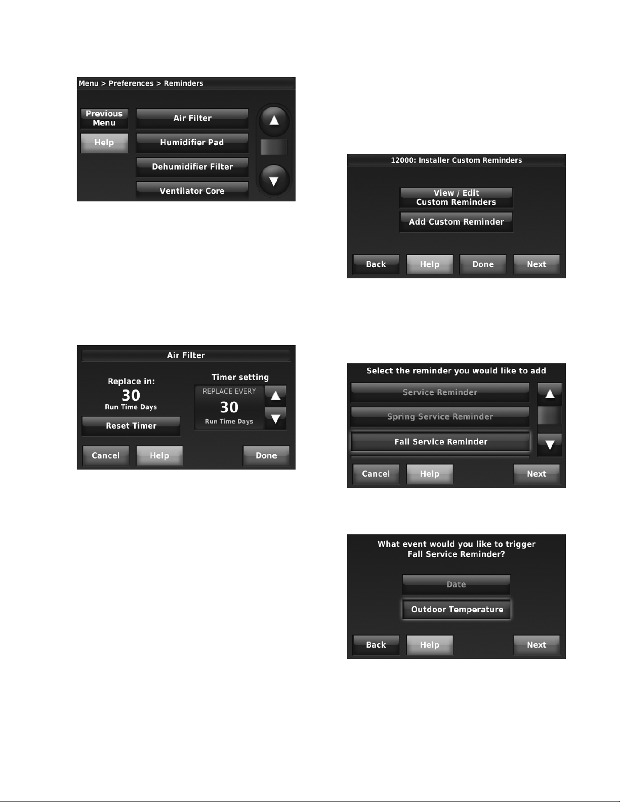
THX9321 PRESTIGE® 2.0 AND THX9421 PRESTIGE® IAQ 2.0 WITH EIM
Fig. 155.
3. Select the reminder you want to set.
4. Press or to set the timer length. Ranges, incre-
ments, and units will change based on the reminder.
• Your Warranty is Expiring Soon
— Set up for recurring or one time only.
• New Custom Reminder
— Enter new reminders or advertisements
— Set up for recurring or one time only.
You can change or create custom reminders in ISU 12000.
NOTE: When set for run time days, the thermostat
tracks the amount of time the fan has run and
compares that time against the number of run
time days selected. Fan run time is counted
when there is a call for forced air heating, cooling, or fan.
Fig. 156.
5. Press Done to save the reminder.
6. Press Reset Timer when you have completed the recom-
mended maintenance or you can extend the timer setting
to turn off the alert and remind you later to do the recommended maintenance.
7. Repeat these steps for all reminders you want to set.
Fig. 157.
For example, to set up a Fall Service Reminder based on
Outdoor Temperature:
1. Press Add Custom Reminder (see Fig. 157).
2. Press Fall Service Reminder and press Next.
Fig. 158.
3. Press Outdoor Temperature and press Next.
CUSTOMIZABLE REMINDERS
The thermostat can be set to alert the user when it is time for
system maintenance or warranty renewal. You can set up to 10
total Custom Reminders on the thermostat and save them to a
USB drive for easy download to multiple thermostats.
Custom Reminders include:
• Service Reminder
— Set up for recurring or one time only.
• Spring Service Reminder
— Provide an alert based on date or outdoor temperature.
• Fall Service Reminder
— Provide an alert based on date or outdoor temperature.
Fig. 159.
4. Press the up or down arrows to set the temperature, and
press Next. A seasonal maintenance reminder will
appear when the outdoor temperature reaches the level
you select, after a specified date.
79 68-0311—01
Page 80

THX9321 PRESTIGE® 2.0 AND THX9421 PRESTIGE® IAQ 2.0 WITH EIM
Fig. 160.
5. Press the up or down arrows to set the date to begin
monitoring outdoor temperature, and press Next. The
thermostat will not display a reminder unless the temperature you set is reached after the date you set at this
screen.
Fig. 161.
6. The preview of the Fall Service Reminder shows you
what you’ve selected. Press Done to accept the
reminder, or press Back to change it.
Fig. 163.
To create a new custom reminder:
1. Press Add Custom Reminder (see Fig. 157).
2. Press New Custom Reminder and press Next.
Fig. 164.
3. Type the name of the reminder, and press Done.
Fig. 162.
7. The Fall Service Reminder will look like this on the Home
Screen:
68-0311—01 80
Fig. 165.
4. Type the reminder message, and press Done.
Fig. 166.
Page 81
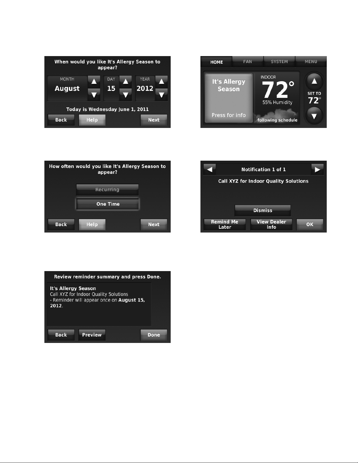
THX9321 PRESTIGE® 2.0 AND THX9421 PRESTIGE® IAQ 2.0 WITH EIM
5. Press the up or down arrows to set the date when the
New Custom Reminder should appear, and press Next.
Fig. 167.
6. Select how often you want the reminder to appear and
press Next.
8. The New Custom Reminder will look like this on the
Home Screen:
Fig. 170.
9. When the user presses the reminder on the Home
screen, the reminder message will be displayed:
Fig. 168.
7. The preview of the custom reminder shows you what
you’ve selected. Press Done to accept the reminder, or
press Back to change it.
Fig. 169.
Fig. 171.
USB PORT
The thermostat has a USB port that allows you to save various
settings to a memory stick and quickly install them on multiple
thermostats.
You can save the following to a memory stick and upload them
individually to the thermostat:
• Installer Setup
• Dealer Information
• Holiday / Event Scheduler (commercial)
—Holidays
— Custom Events
• Custom Reminders
You can also save Data Logs to a memory stick and view
information in a spreadsheet program. See “To save a Data
Log to a memory stick” beginning on page 57.
• Alerts Log
• User Interactions Log
To display USB options, insert a memory stick in thermostat
USB port.
81 68-0311—01
Page 82

THX9321 PRESTIGE® 2.0 AND THX9421 PRESTIGE® IAQ 2.0 WITH EIM
Press MENU
Scroll to select EQUIPMENT STATUS
Press MENU
Scroll to select PREFERENCES
Scroll to select desired option
Press MENU
Scroll to select CLEAN SCREEN
Press YES to lock screen for cleaning
OPERATION
System Status Information
Press MENU, then select EQUIPMENT STATUS.
Depending on how your thermostat was installed, the
Equipment Status screen can report data about the following
systems:
• Heating and cooling
•Fan
• Humidification
• Dehumidification
• Ventilation
• Maintenance reminders
• Thermostat information
NOTE: Press HELP for more information about these
options.
Menu: Preferences
At this screen you can view or change the following options:
• Reminders to change filters
• Display heat/cool diagnostic alerts
• Utility Schedule options
• Fahrenheit/Celsius display
• 12/24-hour clock display
• Screen color and brightness
• Language choice
• Scheduling options
• Adaptive Intelligent Recovery
• Restore default schedule
• Daylight Saving Time options
Menu: Clean Screen
Use this feature to lock the screen so you can clean it without
changing any settings. A countdown timer will show elapsed
time until the screen is reactivated.
68-0311—01 82
NOTE: Do NOT spray any liquid directly on the thermo-
stat. Spray liquids onto a cloth, then use the damp
cloth to clean the screen. Use water or household
glass cleaner. Avoid abrasive cleansers.
Page 83

THX9321 PRESTIGE® 2.0 AND THX9421 PRESTIGE® IAQ 2.0 WITH EIM
Press MENU
Scroll to select SECURITY SETTINGS
Select option, then follow screen prompts
Press MENU
Scroll to select DEALER INFORMATION
Menu: Security Settings
Security options can be used to prevent unauthorized changes
to system settings.
Lock options:
• Unlocked: Full access allowed.
• Partially locked: Only temperature can be changed.
• Fully locked: No access allowed.
If you choose to use a password for additional security, write it
here for reference:
Menu: Dealer Information
Check this screen if you need to contact the person who
installed your system, for maintenance, repairs or upgrades.
NOTE: Press HELP for more information about these
options.
Color Themes
This feature allows you to adjust the color, shade and
brightness of the background and font colors. Use the preview
window in the top-right corner of the thermostat screen to see
the selected color. You can also choose whether or not to
display the cloud on the home screen.
To access this feature, press MENU > Preferences > Display
Options > Themes. See Fig. 172.
Fig. 172.
83 68-0311—01
Page 84

THX9321 PRESTIGE® 2.0 AND THX9421 PRESTIGE® IAQ 2.0 WITH EIM
Display
home
screen
Change
date or
time
Outdoor
temperatu
re and
humidity
Current
system
status
Control
fan
operation
Select
system
type
Display
menu
options
Adjust
temperature
settings
Current program
status
Indoor
temperature and
humidity
Advanced Features
ADAPTIVE INTELLIGENT RECOVERY (RESIDENTIAL USE
ONLY)
Over time, the thermostat “learns” how long it takes your
system to provide the temperature you want. It turns on the
heating or cooling system earlier to make sure you’re
comfortable at the time you expect.
COMPRESSOR PROTECTION
This feature protects your air-conditioning system by forcing
the compressor to pause before restarting, to prevent damage.
During this brief pause, the message “Waiting for Equipment”
is displayed on screen.
Residential Operation
NOTE: In commercial use, press AUTOMATIC or ON to
temporarily override the programmed fan
schedule.
System Settings
1. Press SYSTEM.
Fig. 175.
2. Press any displayed option
• Heat: Thermostat controls only the heating system.
• Cool: Thermostat controls only the cooling system.
• Automatic: Thermostat selects heating or cooling as
needed.
• Off: Heating and cooling system is off. Fan will still
operate if fan is set to On or Circulate.
• Emergency Heat (only for heat pumps with auxiliary
heat): Thermostat controls Auxiliary Heat.
Compressor is not used.
Program Schedules
These default Energy Saver settings can reduce expenses by
as much as 33%.
Fig. 173. Quick reference to residential display.
NOTE: Outdoor temperature and humidity are displayed
only if an optional outdoor air sensor is installed.
Fan Settings
1. Press FAN.
Fig. 174.
2. Press any displayed option:
• On: Fan is always on.
• Automatic: Fan runs only when heating or cooling
system is on.
• Circulate: Fan runs randomly, about 35% of the time
(residential only).
• Follow Schedule: Fan controlled by program.
NOTE: In commercial use, the CIRCULATE option is
not available.
Table 5. Residential Use Default Schedule.
Period
Wake 6:00 am 70° 78° 70° 78°
Leave 8:00 am 62° 85° 62° 85°
Return 6:00 pm 70° 78° 70° 78°
Sleep 10:00 pm 62° 82° 62° 82°
Start
Time
Heat
(Mon-Fri)
Cool
(Mon-Fri)
Heat
(Sat-Sun)
(Sat-Sun)
To adjust program schedules
1. Press MENU.
Fig. 176.
2. Then press CREATE/EDIT SCHEDULE to display
options:
Fig. 177.
• Guide me: This option creates a schedule for you, by
asking simple questions.
• I’ll do it myself: This is a faster way to create a
schedule manually.
• View/Edit: This displays the full schedule, so you can
make quick adjustments.
Cool
68-0311—01 84
Page 85

Fig. 178.
Press to
set “hold”
time
Press to change temperature
Press to
cancel
“hold”
Press to
begin “hold”
Press MENU
Scroll to select VACATION
Follow screen prompts, then press DONE
THX9321 PRESTIGE® 2.0 AND THX9421 PRESTIGE® IAQ 2.0 WITH EIM
Press or at each screen to enter temperatures, dates and
times as prompted, then press DONE.
The temperature you set will be maintained until you return,
then the program schedule will resume.
NOTE: To reduce costs, you should use the pre-set
NOTE: Press HELP at any menu screen for more infor-
Program Schedule Override
Press or to change the temperature. It will be maintained
until the “hold” time you set.
Press the PERMANENT HOLD button to keep the same
temperature until you manually change it or resume the
program schedule.
To cancel these settings at any time, press CANCEL HOLD.
Vacation Scheduling
This feature lets you conserve energy while away, and restores
a comfortable temperature just before you return to your home.
Energy Saver settings.
mation about schedule options.
Menu: Temporary Schedule Changes
Use the thermostat to set temporary schedule changes that
impact the regular schedule for the heating/cooling system.
This feature is useful if your daily schedule sometimes
changes.
Select an option, then follow screen prompts to conserve
energy while you’re away and maintain a comfortable climate
after you return.
After the times you set, the normal program schedule will
resume.
• Stay Home From Work: Ignores the “Away” period and
keeps the temperature at a comfortable level throughout the
day.
• Return Home Early: Shortens the “Away” period and
applies evening temperature settings earlier than usual.
• Return Home Late: Extends the “Away” period, and applies
evening temperature settings later than usual.
• Wake Up Early: Shortens the “Sleep” period and applies
morning temperature settings earlier than usual.
• Stay Up Late: Delays the “Sleep” period to keep the
temperature comfortable until you go to bed.
85 68-0311—01
Page 86

THX9321 PRESTIGE® 2.0 AND THX9421 PRESTIGE® IAQ 2.0 WITH EIM
Press MENU
Scroll to select TEMPORARY SCHEDULE
Select option, then follow screen prompts
3. Select the temperatures you would like to adjust based
4. When asked if you’d like to enter the Utility Schedule
5. Indicate how many different price levels the Utility Sched-
NOTE: Press HELP for more information about these
options.
Fig. 180.
on the Utility Schedule. Choose to create a cost-saving
schedule for the heating system, the cooling system, or
both.
now, press Yes.
ule has, then press Next. At this and the following
screens, you can customize how the system operates for
up to four different price levels, based on local utility
rates.
NOTE: See also “Program Schedule Override” beginning
on page 87
Utility Scheduling
This feature can help reduce fuel or electric expenses by
changing indoor temperatures at certain times of the day when
utility charges rise. For example, the system can be set to raise
indoor temperature slightly in summer (or lower it in winter)
during hours of peak usage when rates are higher.
1. Press MENU, then press Preferences, then press Utility
Schedule Options.
Fig. 179.
2. Press On, then press Next.
Fig. 181.
6. Use the slider to set the warmest heating or coolest cool-
ing temperature allowed during the different price periods.
68-0311—01 86
Fig. 182.
7. Follow the on-screen prompts to set the days of the week
that will use the Utility Schedule, then press Next.
8. The thermostat will prompt you to enter information for
additional price periods, and prompt you to review and
save your Utility Schedule when complete.
Page 87

THX9321 PRESTIGE® 2.0 AND THX9421 PRESTIGE® IAQ 2.0 WITH EIM
Display
home
screen
Change
date or
time
Outdoor
temperatu
re and
humidity
Current
system
status
Control
fan
operation
Select
system
type
Display
menu
options
Adjust
temperature
settings
Press to
override
program
temporarily
Thermostat
location and
current
program
status
Indoor
temperature
and humidity
COMMERCIAL FEATURES
The thermostat can be setup for residential or light commercial
applications (ISU 1010). When the thermostat is setup for
commercial, the thermostat meets commercial code, Title 24
and provides the following features:
• Commercial language (occupied and unoccupied)
• Temporary override (permanent hold is not allowed)
• Temporary override duration is limited to the amount set by
the installer
• Guide me through scheduling
• Adjustable ramp rates
• 365 holiday schedule
• Schedule up to 25 custom events
• Initiate occupancy
• Displays name on home screen
• Remote setback using an occupancy sensor
• Economizer or Time of Day output
• Pre-occupancy purge
• Additional dehumidification control options
NOTE: Outdoor temperature and humidity are displayed
only if an optional outdoor air sensor is installed.
Program Schedules
These default Energy Saver settings can reduce expenses by
as much as 33%.
Table 6. Commercial Use Default Schedule.
Period Start Time Heat Cool Fan
Occupied 1 8:00 am 70° 7° On
Unoccupied 1 10:00 pm 55° 85° Auto
Occupied 2* 12:00 am 70° 75° On
Unoccupied 2* 12:00 am 55° 85° Auto
* Period 2 is cancelled by default. If you activate it, the values
shown above are default settings.
Program Schedule Override
To conserve energy, meet commercial code and be Title 24
compliant, the thermostat allows only a temporary override.
When the user overrides the temperature, the thermostat will
maintain the new temperature for 1 hour. The user can adjust
the hold until time up to the Hold Until time limit, which is set by
the installer in installer setup 4030.
Fig. 183.
Commercial Operation
Home Screen
Fig. 184. Quick reference to commercial display.
Press or to change the temperature. It will be maintained
until the “hold” time you set.
Press OVERRIDE to use a pre-set “occupied” temperature if a
person is present during an unoccupied period. The new
temperature will be maintained for at least 1 hour, and can be
adjusted up to the maximum time set by the installer. To
change the time, press the HOLD UNTIL arrow buttons.
The programmed schedule will resume when the override timer
expires. To cancel the override at any time, press CANCEL
HOLD.
87 68-0311—01
Page 88

THX9321 PRESTIGE® 2.0 AND THX9421 PRESTIGE® IAQ 2.0 WITH EIM
Press to
set “hold”
time
Press to activate “occupied” mode
Press to
cancel
“hold”
Press to
begin “hold”
Press to change temperature
Press MENU
Scroll to select HOLIDAY / EVENT SCHEDULER
Choose an option below
The CUSTOM EVENTS button gives you more options to
customize temperatures for up to 25 specific dates and times,
which can be one-time or recurring events.
Program Override Modes
Holiday/Event Scheduling
This feature lets you conserve energy when the workplace is
unoccupied for special events or on holidays.
The US (United States) and CANADIAN options allow you to
select from a list of holidays commonly observed in each
country. See Fig. 185. You can set the system to “unoccupied”
or “occupied” mode for the days you select.
Fig. 185.
The selected holidays and the custom events can be saved to
USB and uploaded to Prestige 2.0 thermostats.
Holiday Override
Press HOLIDAY MODE to set temperatures that will be
maintained from now until the date you expect to return.
The thermostat will resume the normal schedule on the date
you set. You can press CANCEL at any time to resume the
normal schedule.
NOTE: The cool temperature setting can only be set
higher than the unoccupied program setting and
the heat temperature setting can only be set lower
than the unoccupied program setting.
68-0311—01 88
Page 89

THX9321 PRESTIGE® 2.0 AND THX9421 PRESTIGE® IAQ 2.0 WITH EIM
Scroll to select HOLIDAY MODE
Follow screen prompts, then press DONE
Press to maintain comfortable temperature while room is
occupied
Ramp Rates
When the ramp rate is set to Off, the thermostat begins
recovery at the scheduled time.
When a ramp rate is set, recovery begins early to reach the
setpoint by the program time. Based on your recovery ramp
setting and how far the thermostat is set back, the thermostat
determines how early to turn on the system.
Initiate Occupancy mode
This feature keeps temperature at an energy-saving level until
the PRESS TO START OCCUPANCY button is pressed. When
you arrive, press the button to maintain a comfortable
temperature while the room is occupied.
Press the or buttons to set the temperature or “Hold Until”
time. The temperature is maintained until the time you set.
Temperature returns to an energy-saving level after the timer
expires, or the “Occupied” period ends.
The thermostat keeps temperature at an energy saving level
until OVERRIDE or PRESS TO START OCCUPANCY button is
pressed.
NOTE: This feature is available only if it is programmed
by the installer.
If an outdoor sensor is installed, you can set outdoor
temperatures for mild, cold and hot days in your region. By
setting these outdoor temperatures, the thermostat will
automatically adjust the ramp rate based on outdoor
conditions. This allows the thermostat to save energy by
starting recovery at the optimum time as outdoor conditions
change.
NOTE: The thermostat uses an adjustable ramp rate
when the thermostat is setup for commercial. This
allows the thermostat to recover on time during
changing conditions (occupancy changes, temperature overrides, load conditions, opening/closing of doors etc) which are common in
commercial applications.
Fig. 186.
89 68-0311—01
Page 90
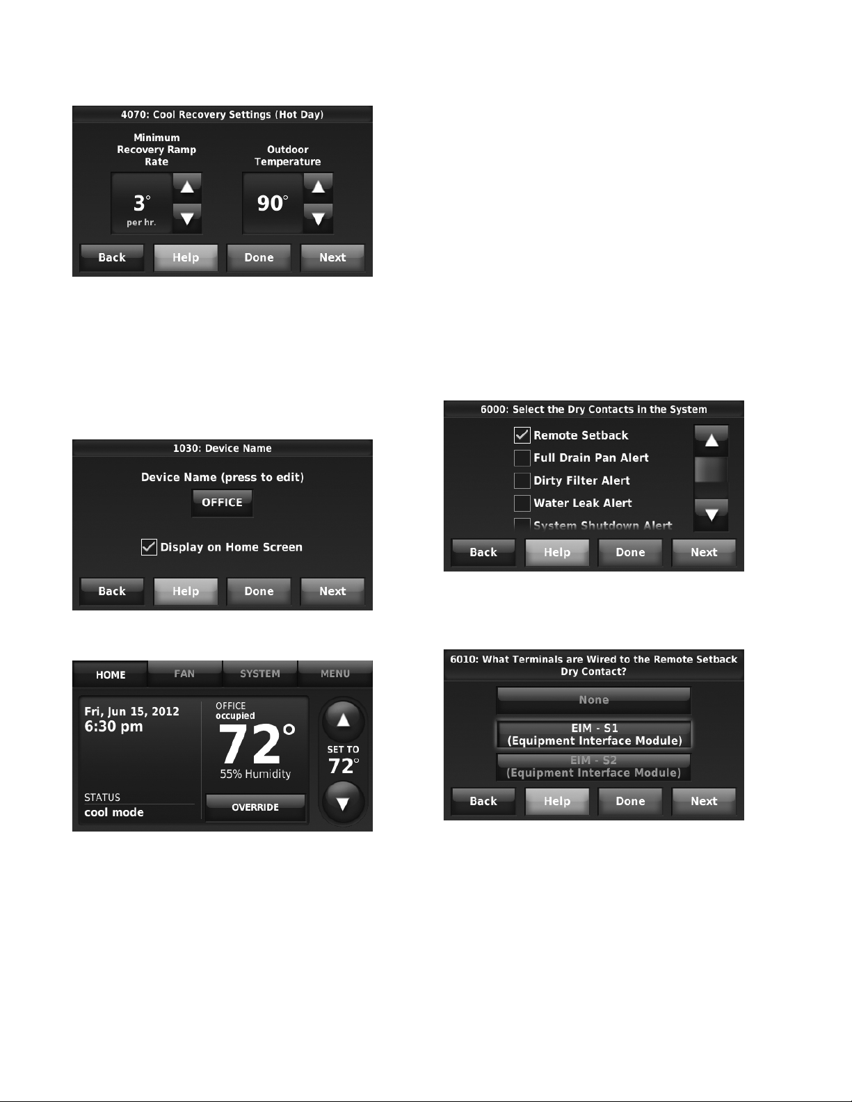
THX9321 PRESTIGE® 2.0 AND THX9421 PRESTIGE® IAQ 2.0 WITH EIM
During occupied periods, the sensor tells the thermostat to go
to STANDBY (setback settings) when no one is in the room. If
someone is in the room, then it follows the settings of the
occupied period. The occupancy sensor is ignored during
unoccupied periods.
If the thermostat is setup for non-programmable, the sensor
tells the thermostat to go to STANDBY settings when no one is
in the room. If someone is in the room, then it follows the
settings set by the user.
A Remote Setback Time Delay (ISU 6030) can be set to force
the thermostat to wait before it switches from occupied settings
to the standby settings. This allows the room to stay
Fig. 187.
Custom Names
The thermostat location (name) can be displayed on the home
screen. See the name “OFFICE” in Fig. 188 and 189. This is
useful when multiple thermostats are mounted in a manager’s
office or equipment room, to quickly identify which thermostat
is in control of a specific zone or area.
comfortable if the room is unoccupied for a short period of
time. When set to 0 minutes, the thermostat will switch from
occupied settings to the standby settings immediately when
the room is unoccupied.
Set Up Remote Setback
1. Select “Remote Setback” as shown in Fig. 190.
Fig. 188.
Fig. 189.
Remote Setback
The thermostat allows you to do REMOTE SETBACK when set
up for commercial use. This feature requires an occupancy
sensor connected to the S1 or S2 terminals at the EIM.
Fig. 190.
2. Select the terminals wired to the Remote Setback Dry
Contact device (occupancy sensor) and press Next.
Fig. 191.
3. Select Normally Open when Occupied or Normally
Closed when Occupied based on the type of dry contact
device installed.
NOTE: Normally Open when Occupied: The Dry Con-
tact device is open when the room is occupied
and will close when the room is unoccupied.
Normally Closed when Occupied: The Dry Contact device is closed when the room is occupied
and will open when the room is unoccupied.
68-0311—01 90
Page 91
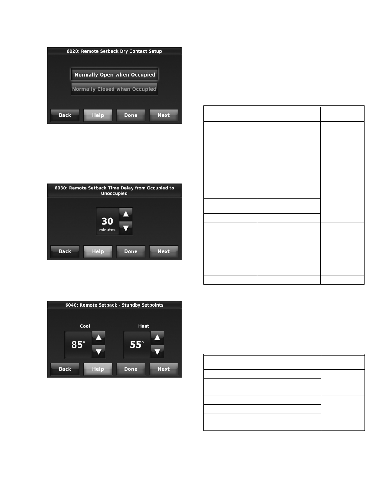
THX9321 PRESTIGE® 2.0 AND THX9421 PRESTIGE® IAQ 2.0 WITH EIM
Fig. 192.
4. Select a Remote Setback Time Delay. The Remote Set-
back Time Delay forces the thermostat to wait before it
switches from occupied settings to the standby settings.
When set to 0 minutes, the thermostat will switch from
occupied settings to the standby settings immediately
when the room is unoccupied.
Fig. 193.
5. Select the Standby settings that you would like to main-
tain when the occupancy sensor detects the room is
unoccupied.
favorable, ventilation with outdoor air can achieve the same
level of comfort at lower cost. Table 7 explains how the
Economizer Module is controlled by the thermostat.
The thermostat works with the Jade W7212 Economizer
Module for conventional systems and the Jade W7213 and
W7214 Economizer Modules for heat pump systems.
Table 7. Economizer Operation.
A-L/A terminal:
Thermostat Mode Equipment Operation
Occupied Heat/Cool/Fan running
Occupied
temporarily
Occupied Heat/Cool/Fan NOT
Occupied
temporarily
Pre-occupancy
purge
Unoccupied Cooling system running
Unoccupied
temporarily
Standby Cooling system running
Unoccupied Cooling system NOT
Unoccupied
temporarily
Standby Cooling system NOT
Non-programmable Fan running
Non-programmable Fan NOT running OFF
Heat/Cool/Fan running
running
Heat/Cool/Fan NOT
running
Fan running
Cooling system running
running
Cooling system NOT
running
running
Economizer
ON
OFF
ON
Time of Day (TOD)
The thermostat can be set up for a Time of Day output in the
installer setup. This output is commonly used to control lighting
panels, turning them on for occupied periods and off for
unoccupied periods. Table 8 explains how the TOD feature
works with various thermostat modes.
Fig. 194.
Economizer and Time of Day (TOD) Operation
Economizer
The thermostat controls an economizer module to provide
ventilation during occupied periods and free cooling when
outdoor conditions are favorable. In some climates the cooling
system may run several hours when it may not be required to
maintain indoor comfort. When outdoor conditions are
Table 8. TOD Operation.
A-L/A terminal:
Thermostat Mode
Occupied
Temperature overrides
Unoccupied
Unoccupied temporarily
Standby
Non-programmable
The Economizer Module and Time of Day output connect to
the A-L/A terminal at the thermostat or EIM and are set up at
ISU 2220.
91 68-0311—01
TOD
ONOccupied temporarily
OFF
Page 92

THX9321 PRESTIGE® 2.0 AND THX9421 PRESTIGE® IAQ 2.0 WITH EIM
Pre-Occupancy Purge
The thermostat can be set up for Pre-Occupancy Purge in the
installer setup (ISU 4010). When setup for Pre-Occupancy
Purge, the thermostat runs the fan 1 to 3 hours before each
occupied period to provide a comfortable workplace upon
arrival. Options are Off and 1 to 3 hours.
Fig. 195.
Fig. 196.
68-0311—01 92
Page 93

Battery Replacement
M32990
M32988
MCR32937
MCR28475
M28896
THX9321 PRESTIGE® 2.0 AND THX9421 PRESTIGE® IAQ 2.0 WITH EIM
Wireless Indoor Sensor
MCR32933
Replace batteries in your indoor sensor when a warning
appears on the thermostat screen, about two months before
batteries are depleted. When the sensor status light begins
flashing red, battery power is critically low and will be depleted
within 2–3 weeks. During normal operation, the status light
remains off. After new batteries are installed, the indoor sensor
will restore communication with the wireless network within a
few seconds.
NOTE: After installing batteries, the status light may
glow amber for up to 20 seconds. Please wait
while the indoor sensor restores communication
with the wireless network.
Wireless Outdoor Sensor
Replace batteries in your outdoor sensor when a warning
appears on the thermostat screen, about two months before
batteries are depleted.
After new batteries are installed, the outdoor sensor will restore
communication with the wireless network within a few seconds.
Portable Comfort Control
SET TO
78
REPLACE
BATTERY
78
Install fresh batteries when the REPLACE BATTERY warning
flashes on the screen. This warning will flash for approximately
two months before the batteries fail.
After batteries are installed, the remote control will
automatically restore communication with the wireless network
within a few minutes.
93 68-0311—01
Page 94
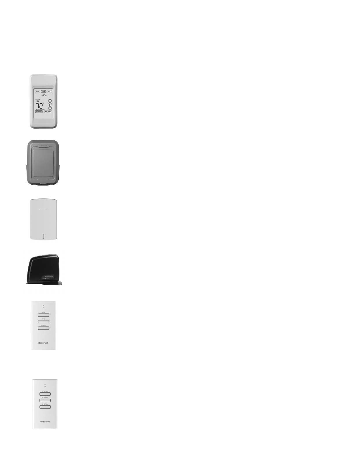
THX9321 PRESTIGE® 2.0 AND THX9421 PRESTIGE® IAQ 2.0 WITH EIM
OPTIONAL ACCESSORIES
PORTABLE COMFORT CONTROL
If you have only one thermostat, you move this remote control
from room to room (like a portable thermostat), to make sure the
temperature is comfortable in the room you’re using. If you have
multiple thermostats, you can view and adjust the temperature in
each room from your armchair.
WIRELESS OUTDOOR SENSOR
With a wireless outdoor sensor, your Prestige® thermostat can
display outside temperature and humidity. This information can
also be displayed on your handheld Portable Comfort Control.
WIRELESS INDOOR SENSOR
If an indoor sensor is installed, your Prestige® thermostat can
monitor the temperature and humidity at that location and adjust
the system to maintain comfort there. With multiple sensors, the
thermostat can average temperature readings from each, to
optimize comfort throughout your home.
REDLINK™ INTERNET GATEWAY
The Honeywell RedLINK Internet Gateway gives you remote
access to your Prestige® thermostat via the Internet or from your
smart phone. You can use a Web browser to review or adjust
indoor temperature, system mode and other settings. The
Gateway can also send alerts to as many as 6 email addresses to
notify you if a problem occurs.
WIRELESS ENTRY/EXIT REMOTE
This handy device mounts beside your door for convenient onetouch control. Press AWAY when you leave, and HOME when you
return, to keep your home comfortable while occupied and save
energy when you’re away. To change pre-set temperatures, go to
Menu > Entry/Exit Remote Settings. Two covers are sold with the
device that allow it to be used in residential or commercial
applications. Residential cover uses HOME, AWAY and
VACATION and the Commercial cover uses OCCUPIED,
UNOCCUPIED and HOLIDAY. The thermostat can work with up to
3 Entry/Exit remotes. Each Entry/Exit remote can control up to 16
thermostats.
WIRELESS VENT AND FILTER BOOST REMOTE
This handy device mounts anywhere in your home (typically
bathroom or kitchen) for convenient on demand ventilation. Select
20, 40 or 60 minutes as desired for increased ventilation. The
thermostat can work with up to 6 Vent Boost remotes.
68-0311—01 94
Page 95

THX9321 PRESTIGE® 2.0 AND THX9421 PRESTIGE® IAQ 2.0 WITH EIM
PORTABLE COMFORT CONTROL
The Portable Comfort Control communicates wirelessly with
the thermostat, and can control up to 16 thermostats, though
each thermostat can only be connected to 1 Portable Comfort
Control.
If you have one thermostat, you move this remote control from
room to room (like a portable thermostat), to make sure the
temperature is comfortable in the room you’re using. If you
have multiple thermostats, you can view and adjust the
temperature in each room from the Portable Comfort Control.
If you have one thermostat, temperature is measured at the
thermostat (Fig. 197) or Portable Comfort Control (Fig. 198),
as you choose.
Fig. 198. Reading temperature at the Portable Comfort
Control.
If the thermostat is being averaged with remote indoor sensors,
and you select THERMOSTAT on the Portable Comfort
Control, you will see the temperature average from the remote
indoor sensors and the thermostat.
NOTE: If the thermostat is not part of the temperature
average, then you will only see the temperature
average from the remote indoor sensors when
you select THERMOSTAT on the Portable Comfort
Control.
Fig. 197. Reading temperature at the thermostat.
If the thermostat is being averaged with remote indoor sensors,
and you select THIS DEVICE on the Portable Comfort Control,
you will see the temperature measured at the Portable Comfort
Control only.
If you have multiple thermostats, temperature is measured at
each thermostat. Press the TOGGLE ZONE arrows to choose
which room to display and adjust. See Fig. 199.
Fig. 199. Portable Comfort Control used with Multiple
Thermostats. Temperature is measured at each
thermostat.
95 68-0311—01
Page 96

THX9321 PRESTIGE® 2.0 AND THX9421 PRESTIGE® IAQ 2.0 WITH EIM
REMOTE INDOOR SENSORS
For installation, see “Mounting C7189R1004 Wireless Indoor
Sensor” on page 14, and “Mounting C7189U1005 Wired
Indoor Sensor” on page 14. For wiring, see “Wiring guide —
Wired Indoor Sensors” on page 119.
Indoor Sensor Operation
Temperature Control
The thermostat can be set to respond to its internal
temperature sensor, or to an optional remote indoor sensor. If
multiple sensors are used, the thermostat will average the
temperature detected at each sensor.
Wireless Indoor Sensor
Fig. 202.
Fig. 200.
Humidification control
If optional remote indoor sensors are installed, you can choose
which sensor you want to use for humidification control. You
can use a different sensor for dehumidification.
NOTE: Requires wireless indoor sensor.
Fig. 201.
Dehumidification control
If optional remote indoor sensors are installed, you can choose
which sensor you want to use for dehumidification control. For
example, you can use one sensor for humidification control,
and another for dehumidification.
NOTE: Requires wireless indoor sensor.
The wireless indoor sensor senses temperature and humidity
in remote locations and communicates that information
wirelessly to the thermostat.
The indoor sensor can be used to do the following:
• Maintain a more consistent temperature throughout the
building by averaging temperatures. Temperatures from all
sensors, including the thermostat, are weighted equally.
• Relocate sensing location (thermostat is in a poor location).
• Relocate the thermostat (if you want to hide the thermostat).
• Humidify and dehumidify in separate spaces (for instance,
humidify on the main level, and dehumidify in the crawl
space).
You can connect up to 6 Wireless Indoor Sensors to the
thermostat. If you connect a Wired Indoor Sensor network (1,
4, 9, etc. sensors) to the S1 or S2 terminals, you can connect
up to 5 Wireless Indoor Sensors to the thermostat.
The indoor air sensor has a 1 year battery life.
Battery level indicators (when batteries are inserted)
• Good: Status light flashes green for 5 seconds.
• Low: Status light flashes red for 5 seconds. Use fresh
batteries.
Battery level indicators (during use)
• Good: Status light remains off.
• Low: Battery power will be depleted in about 2 months.
Thermostat displays Low Battery warning. Status light
remains off.
• Critical: Battery power will be depleted in about 2–3 weeks.
Status light flashes red.
68-0311—01 96
Page 97

THX9321 PRESTIGE® 2.0 AND THX9421 PRESTIGE® IAQ 2.0 WITH EIM
Temperature Display
The temperature reading displayed on the home screen is from
the sensor or sensors that are being used for temperature
control.
In Fig. 203, the temperature reading is the average of the
thermostat internal sensor and the MAIN LEVEL remote
sensor.
Fig. 203.
Humidity Display
If you are sensing Humidity from one location (internal or remote), the humidity reading displayed on the home screen is from the
sensor that is being used for control. In Fig. 204, the humidity reading is from the Main Level Remote Sensor.
Fig. 204.
97 68-0311—01
Page 98

THX9321 PRESTIGE® 2.0 AND THX9421 PRESTIGE® IAQ 2.0 WITH EIM
If you are sensing Humidity from two separate locations (one for humidification and another for dehumidification), you can select
which humidity reading to display on the home screen. In Fig. 205, the humidity reading is from the Main Level Remote Sensor
based on the setting in ISU.
Fig. 205.
68-0311—01 98
Page 99

THX9321 PRESTIGE® 2.0 AND THX9421 PRESTIGE® IAQ 2.0 WITH EIM
Calibration - Outdoor Sensor
The C7089U1006 Outdoor Sensor is calibrated at the factory
and cannot be recalibrated in the field.
Table 9. C7089U1006 Sensor Resistance at
Outdoor Temperature.
Outdoor
Temperature
-20 -28.9 106926 52 11.1 17136
-18 -27.8 100923 54 12.2 16387
-16 -26.7 95310 56 13.3 15675
-14 -25.6 90058 58 14.4 14999
-12 -24.4 85124 60 15.6 14356
-10 -23.3 80485 62 16.7 13743
-8 -22.2 76137 64 17.8 13161
-6 -21.1 72060 66 18.9 12607
-4 -20.0 68237 68 20.0 12081
-2 -18.9 64631 70 21.1 11578
0 -17.8 61246 72 22.2 11100
2 -16.7 58066 74 23.3 10644
4 -15.6 55077 76 24.4 10210
6 -14.4 53358 78 25.6 9795
8 -13.3 49598 80 26.7 9398
10 -12.2 47092 82 27.8 9020
12 -11.1 44732 84 28.9 8659
14 -10.0 42506 86 30.0 8315
16 -8.9 40394 88 31.1 7986
18 -7.8 38400 90 32.2 7672
20 -6.7 36519 92 33.3 7372
22 -5.6 34743 94 34.4 7086
24 -4.4 33063 96 35.6 6813
26 -3.3 31475 98 36.7 6551
28 -2.2 29975 100 37.8 6301
30 -1.1 28558 102 38.9 6062
32 0.0 27219 104 40.0 5834
34 1.1 25949 106 41.1 5614
36 2.2 24749 108 42.2 5404
38 3.3 23613 110 43.3 5203
40 4.4 22537 112 44.4 5010
42 5.6 21516 114 45.6 4826
44 6.7 20546 116 46.7 4649
46 7.8 19626 118 47.8 4479
48 8.9 18754 120 48.9 4317
50 10.0 17926 —
Ohms of
Resistance
Outdoor
Tem per ature
Ohms of
Resistance°F °C °F °C
Calibration - Indoor Sensor
The C7189U1005 Wall Mount Temperature Sensor is
calibrated at the factory and cannot be recalibrated in the field.
Table 10. C7189U1005 Sensor Resistance at
Room Temperature.
Room
Tem per ature
40 4.4 22537 72 22.2 11100
42 5.6 21516 74 23.3 10644
44 6.7 20546 76 24.4 10210
46 7.8 19626 78 25.6 9795
48 8.9 18754 80 26.7 9398
50 10.0 17926 82 27.8 9020
52 11.1 17136 84 28.9 8659
54 12.2 16387 86 30.0 8315
56 13.3 15675 88 31.1 7986
58 14.4 14999 90 32.2 7672
60 15.6 14356 92 33.3 7372
62 16.7 13743 94 34.4 7086
64 17.8 13161 96 35.6 6813
66 18.9 12607 98 36.7 6551
68 20.0 12081 100 37.8 6301
70 21.1 11578 —
Ohms of
Resistance
Room
Temperature
Ohms of
Resistance°F °C °F °C
99 68-0311—01
Page 100

THX9321 PRESTIGE® 2.0 AND THX9421 PRESTIGE® IAQ 2.0 WITH EIM
Backup Control
This section explains when backup control is used. For
example, if batteries in the wireless indoor sensors are
depleted.
If the Thermostat is Part of the Temperature
Average
1. The thermostat controls the system using the remaining
sensors that are part of the temperature average.
2. If there are no remote indoor sensors remaining, the
thermostat controls the system using its internal sensor.
3. If the internal thermostat sensor is not available and a
Return Air Sensor is connected, the Backup Control in
the EIM is used. This backup control maintains 55 °F in
heat, 85 °F in cool and operates the fan continuously to
sense and control temperature.
If the Thermostat is NOT Part of the
Temperature Average
1. The thermostat controls the system using the remaining
sensors that are part of the temperature average.
2. If there are no remote indoor sensors remaining and a
Return Air Sensor is connected, the Backup Control in
the EIM is used. This backup control maintains 55 °F in
heat, 85 °F in cool and operates the fan continuously to
sense and control temperature.
RE-CONNECT THERMOSTAT AND REDLINK
ACCESSORIES
1. Follow the steps in “Link thermostat to EIM or True-
ZONE® Wireless Adapter” on page 10.
2. Follow the steps in “Link Optional RedLINK™ Accessories” on page 11.
To replace a thermostat that is being used
with an Equipment Interface Module (EIM)
AT THE EQUIPMENT INTERFACE MODULE
1. Press and hold the CONNECT button on the EIM until
the status light glows amber (hold for about 10 seconds).
This will disconnect ALL devices from the Equipment
Interface Module.
AT THE PORTABLE COMFORT CONTROL
1. Press and hold the blank space (or arrow if present) in
the lower right hand corner of the screen until the display
changes.
2. Press REMOVE, then YES to disconnect from the old
thermostat.
AT THE ENTRY / EXIT REMOTE AND REDLINK INTERNET
GATEWAY
1. Press and hold the CONNECT button on the RedLINK
accessory until the status light glows amber (hold for
about 10 seconds). This will disconnect the device from
the old thermostat.
Replacing System Components
Follow steps below to disconnect the thermostat, EIM, and
RedLINK accessories.
To replace an Equipment Interface Module
(EIM)
AT THE THERMOSTAT
1. Press MENU > INSTALLER OPTIONS, then enter date
code when prompted (printed on back of thermostat).
NOTE: Or press MENU > EQUIPMENT STATUS to find
the date code.
2. Scroll down to select WIRELESS DEVICE MANAGER.
3. Press REMOVE DEVICE, then select THIS THERMO-
STAT to remove.
AT THE PORTABLE COMFORT CONTROL
1. Press and hold the blank space (or arrow if present) in
the lower right hand corner of the screen until the display
changes.
2. Press REMOVE, then YES to disconnect from the old
Equipment Interface Module.
AT THE INDOOR SENSOR, ENTRY / EXIT REMOTE,
REDLINK INTERNET GATEWAY OR TRUESTEAM
WIRELESS ADAPTER
1. Press and hold the CONNECT button on the RedLINK
accessory until the status light glows amber (hold for
about 10 seconds). This will disconnect the device from
the old Equipment Interface Module or thermostat.
RE-CONNECT THERMOSTAT AND REDLINK
ACCESSORIES
1. Follow the steps in “Link thermostat to EIM or True-
ZONE® Wireless Adapter” on page 10.
2. Follow the steps in “Link Optional RedLINK™ Accessories” on page 11.
To replace a thermostat that is NOT being
used with an Equipment Interface Module
(EIM)
AT THE PORTABLE COMFORT CONTROL
1. Press and hold the blank space (or arrow if present) in
the lower right hand corner of the screen until the display
changes.
2. Press REMOVE, then YES to disconnect from the old
thermostat.
AT THE INDOOR SENSOR, ENTRY / EXIT REMOTE,
REDLINK INTERNET GATEWAY OR TRUESTEAM
WIRELESS ADAPTER.
1. Press and hold the CONNECT button on the RedLINK
accessory until the status light glows amber (hold for
about 10 seconds). This will disconnect the device from
the old thermostat.
RE-CONNECT REDLINK ACCESSORIES
1. Follow the steps in “Link Optional RedLINK™ Accesso-
ries” on page 11.
68-0311—01 100
 Loading...