

Honeywell TH8320R1003, TH8320R1003/U Installation Manual
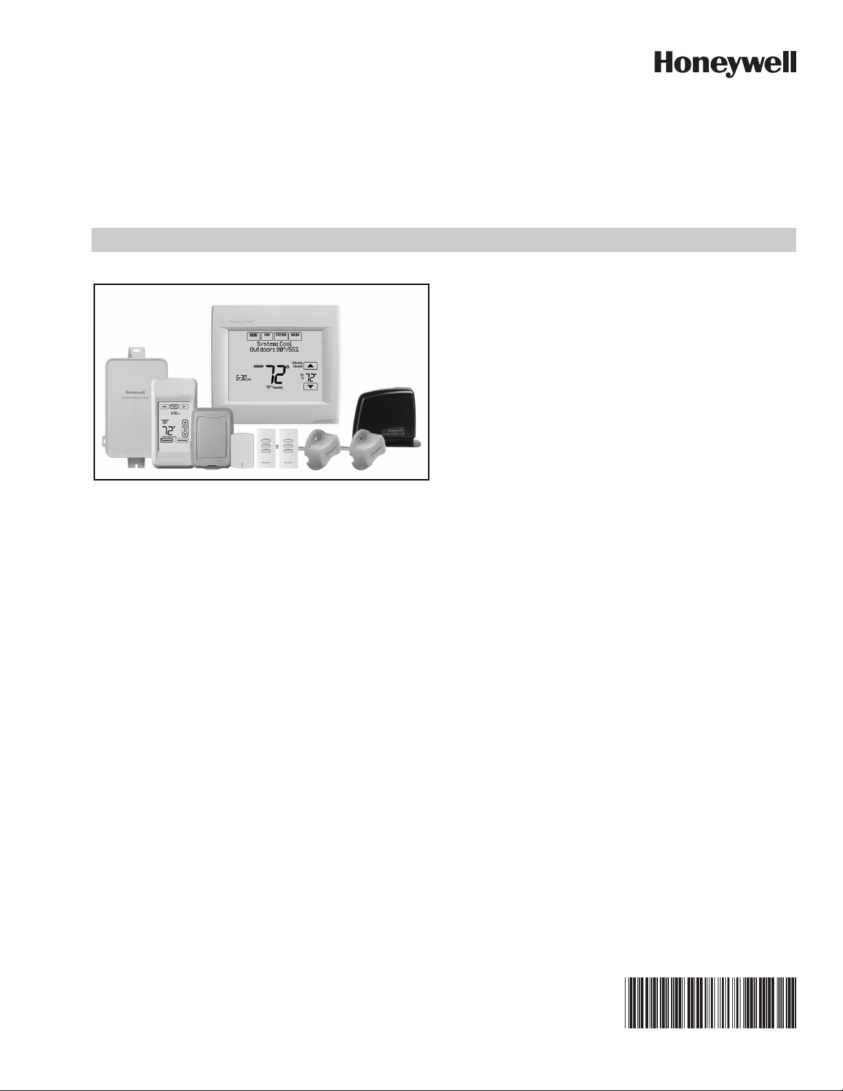
VisionPRO® 8000 with RedLINK™
PRODUCT DATA
• Customizable Service Reminders
Set up to 10 service reminders. Choose from the pre-set
options or customize your own. Reminders can be based
on date or the outdoor temperature.
• Universal Inputs
Thermostat - S1
EIM - S1, S2, S3, S4
Assignable inputs allow you to setup Indoor and Outdoor
Temperature Sensors, Discharge and Return Air Sensors
or Dry Contact Devices. Dry Contact Devices can be used
to trip pre-set or customized alerts on the thermostat home
screen. Note: Dry Contact Alerts require an Equipment
Interface Module (EIM).
• User Interaction Log
The interaction log stores history of thermostat setting
APPLICATION
The VisionPRO® 8000 with RedLINK™ features an effortless,
7-Day programmable touchscreen thermostat that provides
control of temperature, humidification, dehumidification, and
ventilation for up to 4 Heat/2 Cool heat pump systems or up to
3 Heat/2 Cool conventional systems for residential and
commercial applications.
FEATURES
• RedLINK™ Compatible
Increase your content and profit per job by including
RedLINK™ accessories that meet your customers comfort
and convenience needs. RedLINK accessories include the
Wireless Outdoor Sensor, Portable Comfort Control (PCC),
Equipment Interface Module (EIM), RedLINK Internet
Gateway, Wireless Indoor Sensor, TrueSTEAM™ humidifier with Wireless Adapter, TrueZONE™ zoning panel with
Wireless Adapter, Vent Boost Remote and Entry/Exit
Remote.
changes including temperature, system and installer setup.
You can use the interaction log to save time by determining
if the issue is a system error or an accidental user error.
The Interaction Log is only viewable on a computer after
you download it from the thermostat to a microSD card.
• Selectable for Residential and Light Commercial
Applications
One thermostat does it all to meet the needs of Residential
and Light Commercial applications. Simply select Residential or Commercial during the installer setup. If Commercial
is selected, the thermostat will use commercial language,
meet building codes and offer 365 day holiday scheduling.
• MicroSD Card Port for Quick Installer Setup
Save time by using a microSD card to upload installer settings and service reminders in one simple step.
• Selectable Sensors
When paired with a Wireless Indoor Sensor(s) you have
the ability to choose which sensor(s) to use for temperature, humidification and dehumidification. They can be
used in combination for temperature averaging—or individually—to condition humidity levels in separate spaces.
68-0312-03

VISIONPRO® 8000 WITH REDLINK™
CONTENTS
Application ........................................... 1
Specifications ...................................... 3
Ordering Information ........................... 2
System Installation .............................. 6
When Installing this Product... ..................... 6
Installing Equipment Interface Module (if used) 8
Wiring 24 Vac Common ................................ 8
Selecting Discharge and Return Air Temperature
Sensor Mounting Locations ......................... 9
Selecting Discharge and Return Air Temperature Sensor
Mounting Locations .............................................. 9
Selecting Return Air Temperature Sensor Mounting Loca-
tion ....................................................................... 9
Selecting Thermostat Location .................... 11
Installing Wallplate ........................................ 11
Power Optional RedLINK™ Accessories .... 13
Linking Thermostat to Equipment Interface Mod-
ule (if used) .................................................... 14
Linking RedLINK Accessories ..................... 14
Mounting Optional Accessories .................. 58
Data Logs ....................................................... 73
Alerts Log ............................................................. 73
User Interactions Log ........................................... 73
Dry Contact Alerts ........................................ 74
Setting the Time/Date ................................... 61
Setting the Fan .............................................. 61
Setting System Mode .................................... 61
Installer Tests ...................................... 57
Using the Equipment Test ............................ 57
Using the Wireless Signal Strength Test .... 58
Indoor Air Quality (IAQ) Control ......... 80
Humidification ............................................... 80
Set up Humidification ........................................... 80
Control Humidification Level ................................ 82
Dehumidification - Residential ..................... 83
Set up Dehumidification With Cooling System ..... 83
Set up Dehumidification With Whole House Dehumidifier
84
Set up Dehumidification Away Mode ................... 86
Control Dehumidification Level ............................ 87
Dehumidification - Commercial ................... 87
Set up Dehumidification With Cooling System ..... 88
Set up Dehumidification With Dehumidifier .......... 89
Control Dehumidification Level ............................. 90
Ventilation ...................................................... 91
Set up Ventilation ................................................. 92
IAQ Reminders ..................................... 96
Customizable Reminders ................... 96
MicroSD card ....................................... 100
Commercial Features .......................... 102
Preset Energy-Saving Schedules ......................... 62
Advanced Features ....................................... 71
Adaptive Intelligent Recovery (residential use only) 71
Compressor Protection ......................................... 71
Heat Pump and Backup Heat Operation 78
Portable Comfort Control ................... 111
Remote Indoor Sensors ...................... 112
Ramp Rates (Commercial Use) .................... 105
Remote Setback (Commercial Use) ............. 105
Economizer and Time of Day (TOD) Operation
106
Pre-Occupancy Purge ................................... 107
Staging Control ............................................. 76
Optional Accessories .......................... 110
Troubleshooting .................................. 140
Wiring ................................................... 117
EIM Wiring Diagrams .................................... 120
Geothermal Radiant Heat ............................. 78
Wiring IAQ Equipment or a Heat/Cool Stage to the
Universal Terminals ...................................... 129
Economizer Module Wiring Diagrams ......... 132
Wiring C7089U1006 Outdoor Sensor .......... 134
Wiring guide — Wired Indoor Sensors ........ 135
Regulatory Information ....................... 140
ORDERING INFORMATION
When purchasing replacement and modernization products from your TRADELINE® wholesaler or distributor, refer to the
TRADELINE® Catalog or price sheets for complete ordering number. If you have additional questions, need further information,
or would like to comment on our products or services, please write or phone:
1. Your local Honeywell Environmental and Combustion Controls Sales Office (check white pages of your phone directory).
2. Honeywell Customer Care
1885 Douglas Drive North
Minneapolis, Minnesota 55422-4386
3. http://customer.honeywell.com or http://customer.honeywell.ca
International Sales and Service Offices in all principal cities of the world. Manufacturing in Belgium, Canada, China, Czech
Republic, Germany, Hungary, Italy, Mexico, Netherlands, United Kingdom, and United States.
68-0312—03 2
VISIONPRO® 8000 WITH REDLINK™
M34521
4-15/16 (126)
4-5/8
(118)
1-1/8 (29)
3-5/16 (84)
SPECIFICATIONS
Thermostat Description:
Feature Description
Powering method • Common wire or battery
System types (up to
4 heat/2 cool heat
pump and up to 3
heat/2 cool
conventional)
Changeover Manual or Auto changeover selectable
System setting Em Heat-Heat-Off-Cool-Auto
Fan setting Auto-On-Circ-Follow Schedule
Electrical Ratings for: the Equipment Interface Module and
VisionPRO Thermostats
NOTE: To find what terminals are available on the Equip-
ment Interface Module and the VisionPRO Thermostats, see "Terminal Designations" below the table.
Ter minal
W - O/B 18 to 30 VAC and
Y (cooling) 18 to 30 VAC 1.00A
G (fan) 18 to 30 VAC 0.50A
W2 - Aux 1 (heating) 18 to 30 VAC 0.60A
W3 - Aux 2 (heating) 18 to 30 VAC 0.60A
Y2 (cooling) 18 to 30 VAC 0.60A
A-L/A (Output) 18 to 30 VAC 1.00A
U1, U1
U2, U2
U3, U3
• Gas, oil or electric heat with air
conditioning
• Warm air, hot water, high-efficiency
furnaces, heat pumps, steam and
gravity
• Cool only
Voltage
(50/60 Hz)
Max. Current
Rating
1.00A
750 mVDC
30 VAC max. 0.50A
Humidification Setting Range:
10% to 60% RH.
Dehumidification Setting Range:
40% to 80% RH.
Humidity Display Range:
0% to 99%.
Humidity Sensor Accuracy:
± 5% RH from 30% to 50% RH at 75 F.
Cool Indication:
VisionPRO® 8000 with RedLINK™ displays “Cool On” when
the thermostat turns the cooling on.
Heat Indication:
VisionPRO® 8000 with RedLINK™ displays “Heat On” when
the thermostat turns the heating on.
Auxiliary Heat Indication:
VisionPRO® 8000 with RedLINK™ displays “Aux Heat On”
when the thermostat turns the auxiliary heat on.
Interstage Differential:
Comfort:
The thermostat keeps the indoor temperature within 1
degree of the setpoint (droop less control). The thermostat
turns on stage 2 when the capacity on stage 1 reaches 90%.
When the interstage differential is set to 1.0 or higher, the ther-
mostat stages the equipment based on how far the indoor
temperature is from the setpoint (ISU 303 to 309). See
page 27 for more information.
Clock Accuracy: 1 minute per month at 77 °F (25 °C). ± 2
minutes per month over the operating ambient temperature
range.
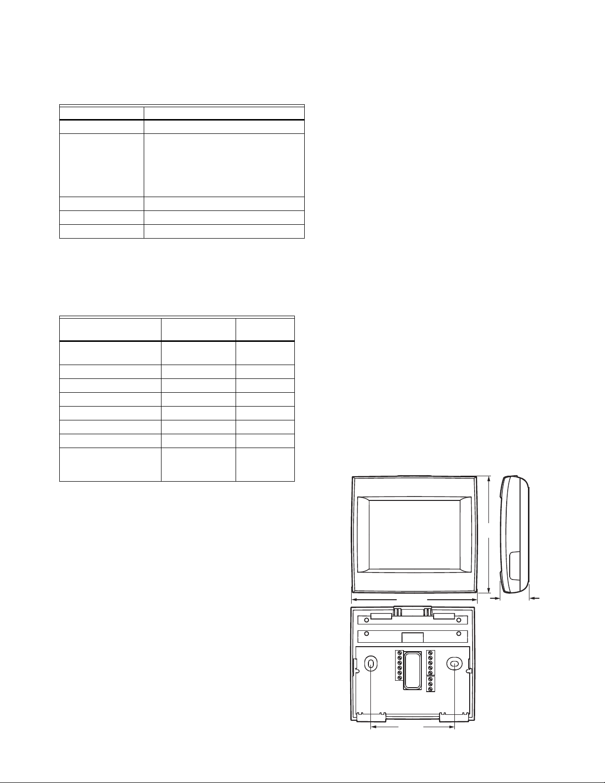
Mounting Means:
Thermostat mounts directly on the wall in the living space
using mounting screws and anchors provided. Fits a horizontal 2 x 4 in. junction box.
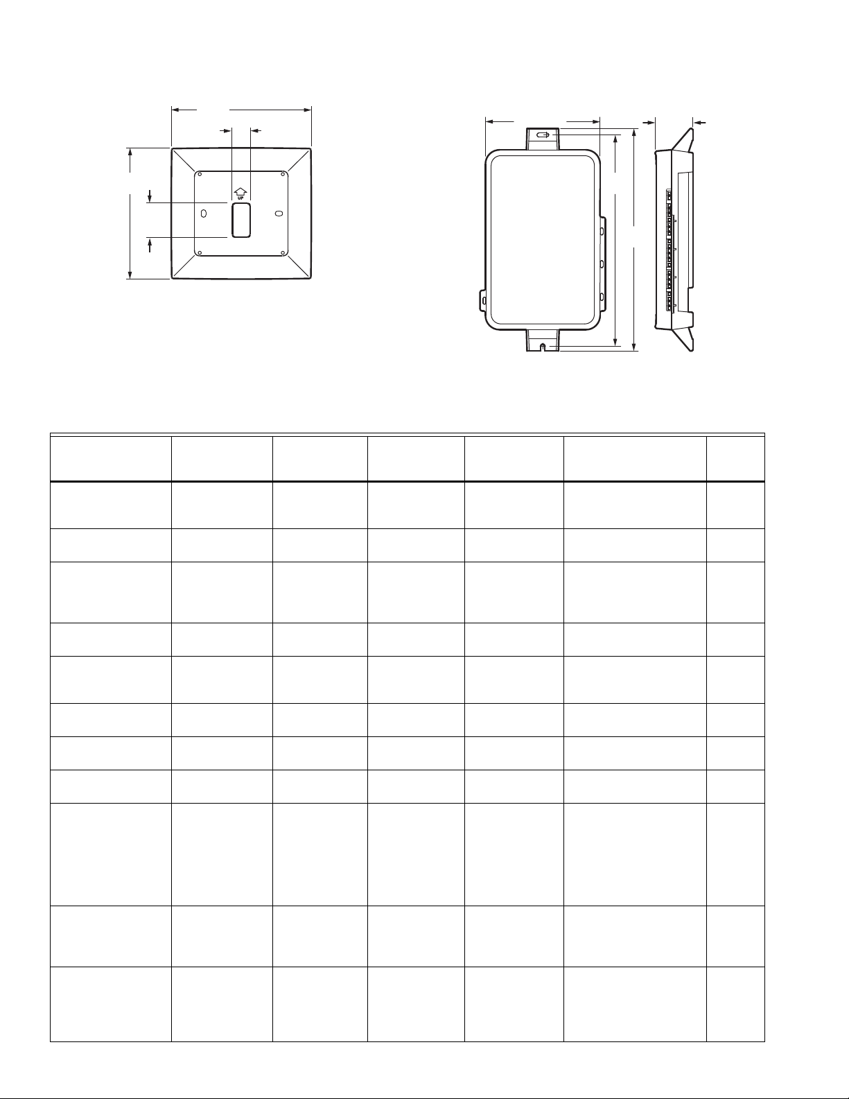
Equipment Interface Module (EIM) mounts on HVAC equip-
ment or on a wall in the equipment room.
Terminal Designations:
— Equipment Interface Module: R, RC, RH, C, W-O/B,
W2-AUX 1, W3-AUX 2, Y, Y2, G, A-L/A, U1 U1, U2 U2,
U3 U3, S1 S1, S2 S2, S3 S3, S4 S4, A, B, C, D
— TH8321 Thermostat: R, RC, C, W-O/B, W2-AUX/E, Y, Y2,
G, A-L/A, K, U1 U1, S1 S1
— TH8320 Thermostat: R, RC, C, W-O/B, W2-AUX/E, Y, Y2,
G, A-L/A, K, S1 S1
— TH8110 Thermostat: R, RC, C, W-O/B, Y, G, K, S1 S1
Power Consumption of TH8321/TH8320/TH8110:
Backlight on: 1.44 VA
Backlight off: 1.32 VA
RedLINK Communication:
Frequency: 900 Mhz frequency range
Re-Sync Time: RedLINK devices re-establish communication
within 6 minutes after AC power resumes.
Temperature Setting Range:
Heating: 40 to 90 °F (4.5 to 32 °C).
Cooling: 50 to 99 °F (10 to 37 °C).
Temperature Sensor Accuracy:
± 1.5 F at 70 F (0.75 C at 21.0 C)
Fig. 1. Dimensions of thermostat in in. (mm).
3 68-0312—03
VISIONPRO® 8000 WITH REDLINK™
M34258
25/32
(20)
6-5/32
(156)
1-1/2
(38)
5-3/4
(146)
Fig. 2. Dimensions of VisionPRO cover plate in in. (mm).
Operating
Ambient
Product Part Number
Thermostat TH8321R1001
TH8320R1003
Temperature
32 to 120 °F
(0 to 48.9 °C)
TH8110R1008
Equipment Interface
Module
Wireless Adapter
(For TrueZONE,
YTHM5421R1010*
THM5421R1021
-40 to 165 °F
(-40 to 73.9 °C)
THM4000R1000 -40 to 165 °F
(-40 to 73.9 °C)
TrueSTEAM or extend
wireless range of EIM)
RedLINK Internet
Gateway
Portable Comfort
Control
Wireless Entry/Exit
Remote
Wireless Vent and Filter
Boost Remote
Wireless Outdoor
Sensor
THM6000R1002 32 to 120 °F
(0 to 48.9 °C)
REM5000R1001 32 to 120 °F
(0 to 48.9 °C)
REM1000R1003 32 to 120 °F
(0 to 48.9 °C)
HVC20A1000 32 to 120 °F
(0 to 48.9 °C)
C7089R1013 -40 to 140 °F
(-40 to 60 °C)
Wireless Indoor Sensor C7189R1004 0 to 120 °F
(-17.8 to 48.9 °C)
Fig. 3. Dimensions of Equipment Interface Module in in.
Operating
Relative Humidity
5% to 90%
Non-Condensing
5% to 95%
Non-Condensing
5% to 95%
Non-Condensing
5% to 95%
Non-Condensing
5% to 90%
Non-Condensing
5% to 90%
Non-Condensing
5% to 90%
Non-Condensing
0% to 100%
Condensing
5% to 90%
Non-Condensing
4-53/64 (123)
Shipping
Temperature
-20 to 120 °F
(-28.9 to 48.9 °C)
-20 to 165 °F
(-28.9 to 73.9 °C)
-20 to 165 °F
(-28.9 to 73.9 °C)
-20 to 120 °F
(-28.9 to 48.9 °C)
-20 to 120 °F
(-28.9 to 48.9 °C)
-20 to 120 °F
(-28.9 to 48.9 °C)
-20 to 120 °F
(-28.9 to 48.9 °C)
-40 to 120 °F
(-40 to 48.9 °C)
-20 to 120 °F
(-28.9 to 48.9 °C)
1-19/32
(41)
8-7/8
(225)
9-11/32
(237)
M33331
(mm).
Physical Dimensions in in.
(mm) Color(s)
4-15/16 x 4-5/8 x 1-1/8
(126 x 118 x 29)
9-11/32 x 4-53/64 x 1-19/32
(237 x 123 x 41)
5-9/16 x 4-3/8 x 1-1/4
(141 x 112 x 32)
6 x 4-7/8 x 2-1/2
(152 x 124 x 64)
6-1/4 x 3-1/8 x 1-5/8
(158 x 80 x 38)
3-15/16 x 1-15/16 x 5/8
(101 x 50 x 16)
3-15/16 x 1-15/16 x 5/8
(101 x 50 x 16)
5 x 3-1/2 x 1-11/16
(127 x 89 x 43)
2-7/8 x 1-7/8 x 15/16
(74 x 48 x 24)
Arctic
White
Gray
Gray
Black
Arctic
White,
Gray
Arctic
White
Arctic
White
Gray
Arctic
White
For optimal
Battery Life:
35 to 114 °F
(1.7 to 45.6 °C)
Wired Outdoor Sensor
(10K ohm Negative
Temperature
Coefficient)
Wired Wall Mount
Indoor Sensor
C7089U1006 -40 to 120 °F
C7189U1005 45 to 88 °F
(-40 to 48.9 °C)
(7 to 32 °C)
(10K ohm Negative
Temperature
Coefficient)
68-0312—03 4
5% to 95%
Non-Condensing
5% to 95%
Non-Condensing
-40 to 130 °F
(-40 to 54.4 °C)
-20 to 120 °F
(-28.9 to 48.9 °C)
1-1/2 (38) - -
2-9/32 x 1-1/2 x 11/16
(58 x 38 x 18)
Premier
White

Product Part Number
Wired Wall Mount
Indoor Sensor
(20K ohm Negative
Temperature
Coefficient)
Wired Wall Mount
Indoor Sensor
(10K ohm Negative
Temperature
Coefficient)
Wired Flush Mount
Indoor Sensor
(20K ohm Negative
Temperature
Coefficient)
Wired Flush Mount
Indoor Sensor
(20K ohm Negative
Temperature
Coefficient)
Discharge or Return Air
Sensor
(10K ohm Negative
Temperature
Coefficient)
Discharge or Return Air
Sensor
(20K ohm Negative
Temperature
Coefficient)
Discharge or Return Air
Sensor
(20K ohm Negative
Temperature
Coefficient)
Occupancy Sensor for
Remote Setback
(Requires an
Equipment Interface
Module)
VISIONPRO® 8000 WITH REDLINK™
Operating
Ambient
Temperature
TR21 45 to 99 °F
(7 to 37 °C)
TR21-A 45 to 99 °F
(7 to 37 °C)
C7772A1004 45 to 99 °F
(7 to 37 °C)
C7772A1012 45 to 99 °F
(7 to 37 °C)
*
C7735A1000
0 to 200 °F
(- 17.8 to 93.3 °C)
Operating
Relative Humidity
5% to 95%
Non-Condensing
5% to 95%
Non-Condensing
5% to 95%
Non-Condensing
5% to 95%
Non-Condensing
Shipping
Temperature
-40 to 150 °F
(-40 to 65.5 °C)
-40 to 150 °F
(-40 to 65.5 °C)
-40 to 150 °F
(-40 to 65.5 °C)
-40 to 150 °F
(-40 to 65.5 °C)
- - -20 to 120 °F
(-28.9 to 48.9 °C)
Physical Dimensions in in.
(mm) Color(s)
4-9/16 x 3 x 7/8
(116 x 76.5 x 22)
4-9/16 x 3 x 7/8
(116 x 76.5 x 22)
4-1/2 x 2-3/4 x 5/16
(114 x 70 x 8)
4-1/2 x 2-3/4 x 5/16
(114 x 70 x 8)
Probe:
3-3/4 x 1/4 (77 x 6.4)
Cap Diameter:
2-7/16 (62)
C7041 - - - - - - 4-3/16 x 2-5/16 x 1-11/16
(107 x 59 x 43)
C7770A1006 45 to 99 °F
(7 to 37 °C)
WSK-24 Receiver:
- 5 to 140 °F
(-21 to 60 °C)
Door Sensor:
-4 to 140 °F
(-20 to 60 °C)
5% to 95%
Non-Condensing
-40 to 150 °F
(-40 to 65.5 °C)
Probe: 6 x 1/4
(152 x 6.4)
- - - - Receiver:
3.6 x 3.4 x 1.2
(91.4 x 86.4 x 30.5)
Door Sensor:
1.4 x 2.3 x 0.6
(35.8 x 57.6 x 15.2)
White
White
Brushed
Stainless
Steel
Brushed
Stainless
Steel
Gray
- -
- -
White
PIR Sensor:
2.8 x 3.9 x 1.1
(71 x 100 x 28)
(146 x 156)
Arctic
White
Coverplate
(covers marks left by
PIR Sensor:
-4 to 104 °F
(-20 to 40 °C)
THP2400A1019 - - - - - - 5-3/4 x 6-5/32
old thermostats)
Wire Saver Module THP9045A1023 -40 to 163 °F
(-40 to 73 °C)
5% to 90%
Non-Condensing
-40 to 185 °F
(-40 to 85 °C)
- - Gray
* The YTHM5421R1010 Equipment Interface Module Kit includes 50062329-001 Discharge/Return Air Sensors. Replacement Dis-
charge/Return Air Sensor part number is C7735A1000.
5 68-0312—03
VISIONPRO® 8000 WITH REDLINK™
Residential/Résidentiel
1-800-468-1502
http://yourhome.honeywell.com
Commercial/Commerciale
1-888-245-1051
http://customer.honeywell.com
Honeywell, Golden Valley, MN 55422
RoHs Compliant
Conformité RoHs
Assembled in Mexico
Assemblé au Mexique
TH8321R1001
1
1324
Password
(Date Code)
SYSTEM INSTALLATION
When Installing this Product...
1. Read these instructions carefully. Failure to follow the
instructions can damage the product or cause a hazardous condition.
2. Check the ratings given in the instructions to make sure
the product is suitable for your application.
3. Installer must be a trained, experienced service
technician.
4. After completing installation, use these instructions to
verify the product operation.
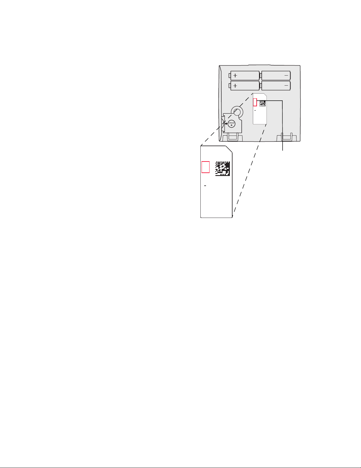
Finding Your Password (Date Code)
You will need the thermostat password to:
• Add or remove RedLINK accessories
• Make changes to Installer Setup
• Perform an Installer Test
• Reset Thermostat to Factory Default Settings
The password (date code) is located on the back of the
thermostat (see Fig. 4)
RoHs Compliant
Conformité RoHs
Assembled in Mexico
Assemblé au Mexique
1324
1
TH8321R1001
Residential/Résidentiel
1-800-468-1502
http://yourhome.honeywell.com
Commercial/Commerciale
1-888-245-1051
http://customer.honeywell.com
Honeywell, Golden Valley, MN 55422
Fig. 4. Finding thermostat password.
You can also find the password (date code) by pressing MENU,
selecting Dealer Information and then scrolling down to see the
Date Code.
68-0312—03 6
VISIONPRO® 8000 WITH REDLINK™
TM
TM
OR
OR
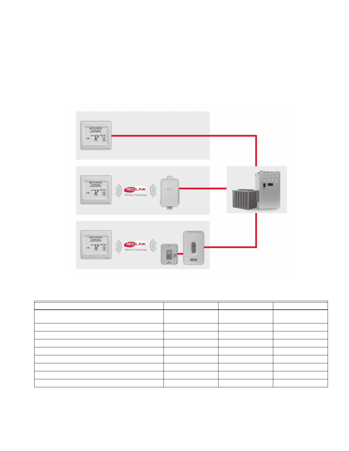
Wired Directly to Equipment
2 Wires for Power or
Battery Only (no wires)
2 Wires for Power or
Battery Only (no wires)
Dual Powered - C Wire or Battery
(C wire or Wire Saver required to use RedLINK accessories)
RedLINK to Equipment Interface Module
RedLINK to TrueZONE Wireless Adapter
INSTALLATION OPTIONS
The VisionPRO® 8000 with RedLINK™ system can be wired directly to the equipment, used with an Equipment Interface Module,
or with a TrueZONE wireless adapter.
If using the Equipment Interface Module, see “Installing Equipment Interface Module (if used)” on page 8.
If using a TrueZONE wireless adapter, follow the installation instructions that came with the TrueZONE panel, and go to “Selecting
Thermostat Location” beginning on page 11.
Model Numbering TH8321 TH8320 TH8110
Stages 3H/2C HP
Residential or Commercial
Dual Powered - C Wire or Battery
Onboard Humidity Sensor
Number of Universal Relays 1 0 0
Number of Universal Sensor Inputs 1 1 1
Economizer / TOD Output
Works with Optional Equipment Interface Module*
Works with Optional TrueZONE Wireless Adapter*
* The relay outputs and inputs on the thermostat do not function when used with an Equipment Interface Module or the TrueZONE
Wireless Adapter.
* If the thermostat has been setup WITHOUT an Equipment Interface Module or the TrueZONE Wireless Adapter and you would
like to add one, you must reset the thermostat back to factory defaults. Press MENU > Installer Options > scroll down to select
Reset to Defaults.
Fig. 5. VisionPRO® 8000 with RedLINK™ installation options.
3H/2C HP
2H/2C CONV
7 68-0312—03
2H/2C CONV
1H/1C HP
1H/1C CONV
VISIONPRO® 8000 WITH REDLINK™
CAUTION
EIM
A
B
C
D
WIRELESS
ADAPTER
CONNECT
POWER
THM4000R
CONNECTED
WIRELESS SETUP
Guidelines for Installing RedLINK Devices
— When installing more than one Thermostat and Equipment
Interface Module, mount the Equipment Interface Modules
at least 2 feet apart for best RedLINK performance. No
minimum distance is required between the Thermostats if
the Thermostat is linked to an Equipment Interface Module.
— When the Thermostat is wired directly to the equipment (No
Equipment Interface Module and No TrueZONE Wireless
Adapter), mount the Thermostats at least 2 feet apart for
best RedLINK performance.
— To determine if a RedLINK device will communicate
properly in the installed location, during the connection
process, press and quickly release the connect button on
the RedLINK device at the desired mounting location
. If the
RedLINK device connects, then it will work reliably during
normal operation. If the RedLINK device does NOT
connect, try a new location. During the connection process,
the signal is sent at low power and during normal operation
the signal is sent at high power.
— To connect a RedLINK device, make sure to press and
quickly release the connect button on the RedLINK device.
Press and holding the connect button down too long will not
allow the device to connect.
— If you link the Thermostat to the TrueZONE Wireless
Adapter, you will NOT be able to do the following: control
humidification, dehumidification or ventilation, setup a
program schedule remotely from a computer, smart phone
or tablet, work with the Wireless Indoor Sensor, Entry / Exit
Remote or the Vent and Filter Boost Remote. To use these
features, wire the Thermostat directly to the zone panel or
use an Equipment Interface Module.
— If you are using a RedLINK device from a previous
installation, you must reset the device first before you reconnect it to the new Thermostat/Equipment Interface
Module. See page 116 for more information.
Installing Equipment Interface Module (if used)
If no Equipment Interface Module is used, skip to “Selecting
Thermostat Location” beginning on page 11.
NOTE: If an EIM is mounted inside a metal cabinet, such
as a commercial rooftop unit, it is recommended
to use a THM4000R1000 Wireless Adapter for
extended wireless range. Mount the Wireless
Adapter outside the metal cabinet and connect to
the ABCD terminals at the EIM. The Wireless
Adapter functions as a remote antenna for the
EIM. After it is wired to the EIM, it automatically
takes over as the antenna for RedLINK communication. For best RedLINK performance, avoid
mounting the Wireless Adapter above the roof
deck or outside the exterior walls.
NOTE: If you install more than one thermostat and EIM,
the EIMs must be at least 2 feet apart for best
RedLINK performance.
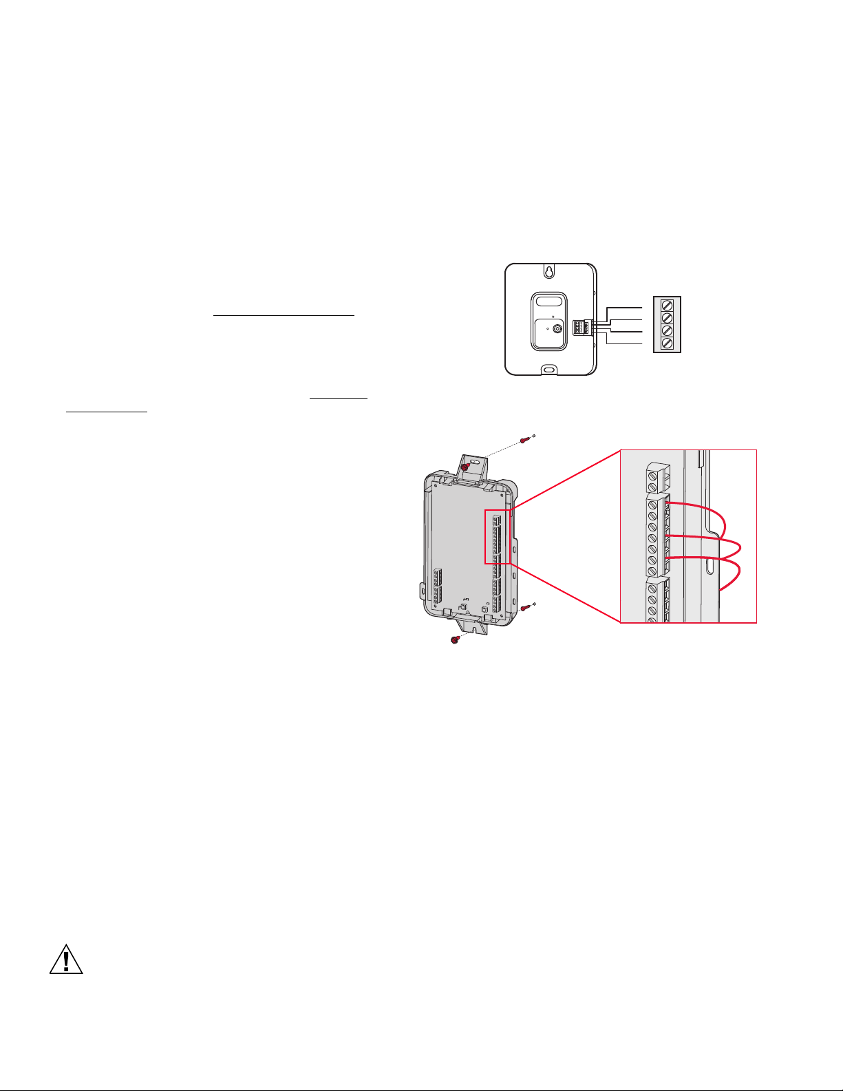
The Equipment Interface Module (EIM) can be mounted
vertically on the HVAC equipment or on a wall in the equipment
room.
1. Mount the EIM near the HVAC equipment, or on the
equipment itself. Use screws & anchors as appropriate
for the mounting surface.
2. To wire the EIM, strip 1/4” insulation, then insert wires
(see Fig. 7). For wiring diagrams, see “Wiring” beginning
on page 117.
Fig. 6. THM4000R1000 Wireless Adapter wired to the EIM.
R
C
W
O/B
W2
AUX1
W3
AUX2
Y
Y2
G
A
L/A
CO
NNECTED
C
O
NN
E
C
T
MCR34049A
Fig. 7.
NOTE: Link EIM to thermostat BEFORE linking any
RedLINK accessories. See “Linking RedLINK
Accessories” on page 14.
3. If you are installing discharge and return air sensors, see
“Selecting Discharge and Return Air Temperature Sensor Mounting Locations” beginning on page 9).
Wiring 24 Vac Common
• Single-Transformer System—Connect the common side of
the transformer to the C screw terminal of the EIM. Leave
the metal jumper wires in place between R, RC, and RH.
• Two-Transformer System—Connect the common side of the
cooling transformer to the C screw terminal of the EIM.
Remove the metal jumper wire between RC and RH.
Connect the hot side of heating transformer to RH and leave
the jumper wire between R and RC and connect the hot
side of cooling transformer to R or RC.
Electrical Hazard.
Can cause electrical shock or equipment damage.
Disconnect power before wiring.
68-0312—03 8
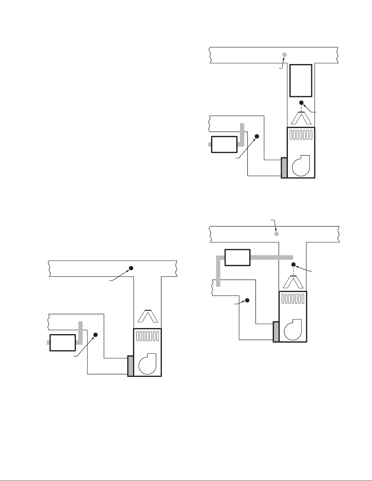
Selecting Discharge and Return Air
MOUNT DISCHARGE
SENSOR HERE
M33074
HEAT
EXCHANGER
BLOWER
VENTILATOR
OR
DEHUMIDIF IER
MOUNT RETURN
SENSOR HERE
DOWNSTREAM OF
VENTILATOR OR
DEHUMIDIFIER
A-COIL
M34807
HEAT
EXCHANGER
BLOWER
MOUNT RETURN
SENSOR HERE
DOWNSTREAM OF
DEHUMIDIFIER
ALTERNATE MOUNTING LOCATION
FOR DISCHARGE SENSOR.
MOUNT
DISCHARGE
SENSOR HERE
ABOVE CENTER
OF A-COIL
UPSTREAM OF
DEHUMIDIFIER
DEHUMIDIFIER
Temperature Sensor Mounting
Locations
Refer to the guidelines below and Fig. 8–12 for mounting
locations of the Discharge and Return Air Temperature
Sensors.
Selecting Discharge Air Temperature
Sensor Mounting Location
1. Mount the Discharge Air Temperature Sensor on the
supply duct in a location where the air is mixed well.
Mount the Discharge Air Temperature Sensor out of sight
of the A-Coil/Heat Exchanger when possible. See Fig. 8.
2. When possible, mount the Discharge Air Temperature
Sensor upstream of a Steam Humidifier, a Fan Powered
Humidifier or a Dehumidifier that is ducted to the supply.
See Fig. 9–10.
3. If space does not allow a Discharge Air Temperature
Sensor upstream of a Steam Humidifier or Fan Powered
Humidifier, mount the Discharge Air Temperature Sensor
downstream of the Humidifier. See Fig. 9.
4. If a Bypass Humidifier is installed, mount the Discharge
Air Temperature Sensor downstream of the Bypass
Humidifier. See Fig. 11–12.
ALTERNATE MOUNTING LO CATION
FOR DISCHAR GE SENSO R.
VENTILATOR
OR
DEHUMIDIF IER
MOUNT RETURN
SENSOR HERE
DOWNSTREAM OF
VENTILATOR OR
DEHUMIDIFIER
VISIONPRO® 8000 WITH REDLINK™
STEAM OR
FAN
POWERED
HUMIDIFIER
MOUNT
DISCHARGE
SENSOR HERE
ABOVE CENTER
OF A-COIL
HEAT
EXCHANGER
BLOWER
UPSTREAM OF
STEAM OR FAN
POWERED
HUMIDIFIER
M34806
Fig. 9.
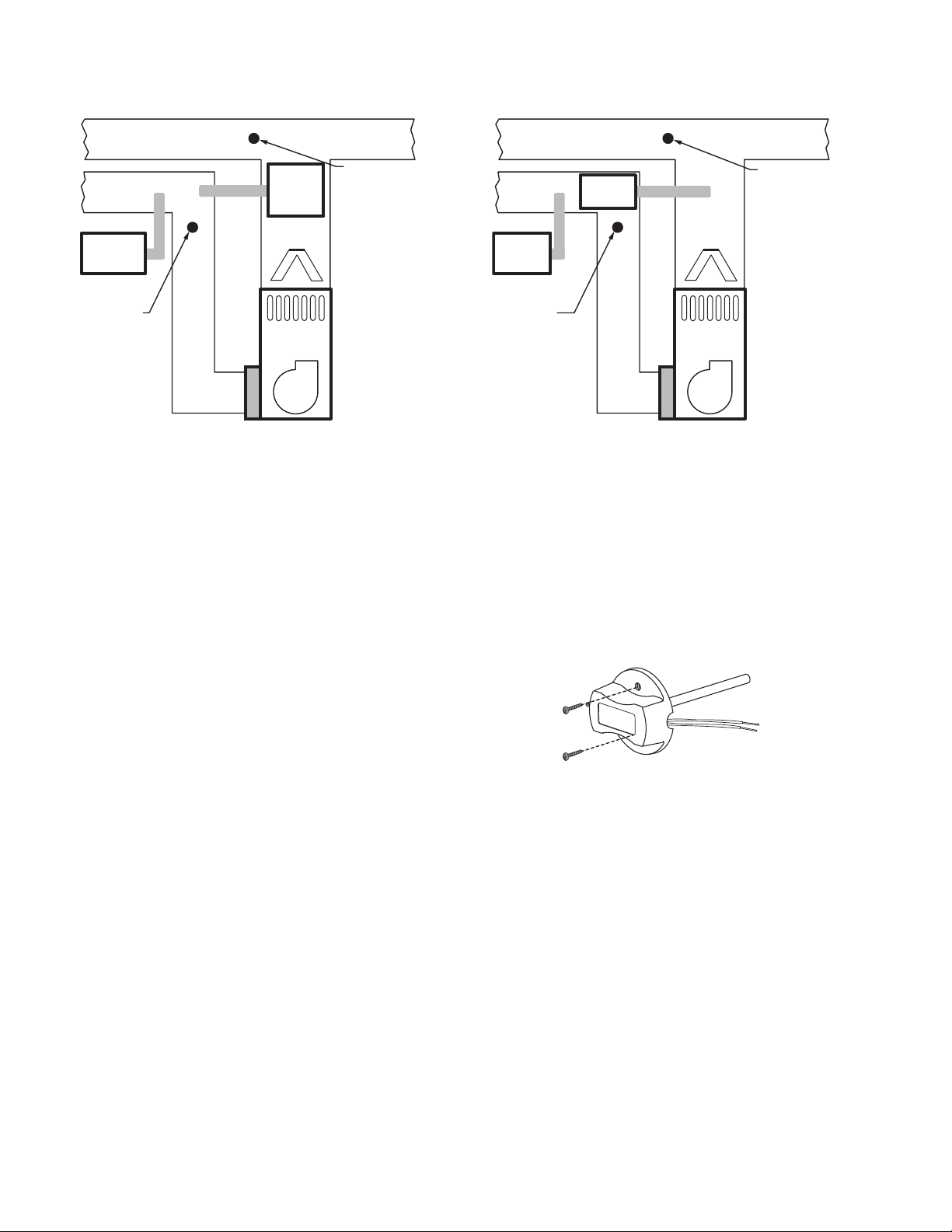
Selecting Return Air Temperature Sensor
Mounting Location
1. Install the Return Air Temperature Sensor on the return
duct in a location where the air is mixed well. Mount the
Return Air Temperature Sensor downstream of a Bypass
Humidifier, Dehumidifier or Ventilator. See Fig. 8–12.
Fig. 10.
Fig. 8.
9 68-0312—03
VISIONPRO® 8000 WITH REDLINK™
MOUNT RETURN
SENSOR HERE
MOUNT DOWNSTREAM
OF BYPASS HUMIDIFIER,
DEHUMIDIFIER OR
VENTILATOR
HEAT
EXCHANGER
BLOWER
VENTILATOR
OR
DEHUMIDIF IER
MOUNT
DISCHARGE
SENSOR HERE
MOUNT
DOWNSTREAM
OF BYPASS
HUMIDIFIER
BYPASS
HUMIDIFIER
M33078A
MOUNT RETURN
SENSOR HERE
MOUNT DOWNSTREAM
OF BYPASS HUMIDIFIER,
DEHUMIDIFIER OR
VENTILATOR
HEAT
EXCHANGER
BLOWER
VENTILATOR
OR
DEHUMIDIFIER
MOUNT
DISCHARGE
SENSOR HERE
BYPASS
HUMIDIFIER
M33079A
M32995
Fig. 11.
Fig. 12.
Installing Discharge and Return Air Temperature Sensors
Use the following steps to mount the Discharge/Return Air
Sensors:
1. Attach plastic cover to the sensor probe.
2. Drill 1/4-inch hole for the sensor probe and mount it to
the ductwork with enclosed screws (see Fig. 13).
3. Connect wires to S1, S2, S3 or S4 terminals at the EIM.
4. Setup the S1, S2, S3 or S4 terminals in the Installer
Setup at the thermostat.
Fig. 13. Mounting Discharge/Return Air Sensor.
68-0312—03 10
VISIONPRO® 8000 WITH REDLINK™
CAUTION
5 FEET
[1.5 METERS]
YES
NO
NO
NO
M19925
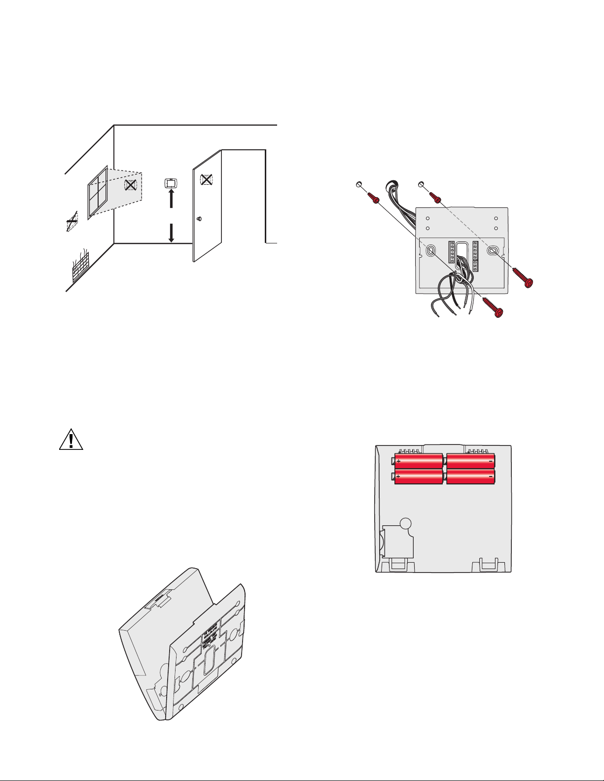
Selecting Thermostat Location
Install the thermostat about 5 ft. (1.5m) above the floor in an area
with good air circulation at average temperature. See Fig. 14.
Fig. 14. Selecting thermostat location.
Do not install the thermostat where it can be affected by:
— Drafts or dead spots behind doors and in corners.
— Hot or cold air from ducts.
— Radiant heat from sun or appliances.
— Concealed pipes and chimneys.
— Unheated (uncooled) areas such as an outside wall behind
the thermostat.
2. Position and level the wallplate (for appearance only).
3. Use a pencil to mark the mounting holes.
4. Remove the wallplate from the wall and, if drywall, drill
two 3/16-in. holes in the wall, as marked. For firmer
material such as plaster, drill two 7/32-in. holes. Gently
tap anchors (provided) into the drilled holes until flush
with the wall.
5. Position the wallplate over the holes, pulling wires
through the wiring opening. See Fig. 16.
6. Insert the mounting screws into the holes and tighten.
C
S1
K
R
C
R
U1
U1
U2
U2
S1
S1
S1
W
O/B
Y
Y
G
G
AUX
W2
-E
Y2
Y2
L/A
A
Fig. 16. Mounting wallplate.
Installing VisionPRO® 8000 with RedLINK™
Installing Wallplate
Electrical Hazard.
Can cause electrical shock or equipment damage.
Disconnect power before wiring.
NOTE: For best RedLINK performance, mount thermo-
stats at least 2 feet apart.
The thermostat can be mounted horizontally on the wall or on a
4 in. x 2 in. (101.6 mm x 50.8 mm) wiring box.
1. Press button on top and pull to remove the wallplate.
Connect Power
1. Insert supplied AA alkaline batteries for primary or
backup power.
Fig. 17. Insert AA batteries.
NOTE: When the thermostat is NOT used with the Equip-
ment Interface Module or the TrueZONE Wireless
Adapter, a C wire is required for RedLINK.
Fig. 15. Separate wallplate from thermostat.
11 68-0312—03
VISIONPRO® 8000 WITH REDLINK™
S1
S1
W
Y
G
W2
Y2
A
S1
S1
O/B
Y
G
AUX
-E
Y2
L/A
K
RC
R
U1
U1
U2
U2
C
CONVENTIONAL
HEAT PUMP
S1
S1
W
Y
G
W2
Y2
A
S1
S1
O/B
Y
G
AUX
-E
Y2
L/A
K
RC
R
U1
U1
U2
U2
C
CONVENTIONAL
HEAT PUMP
S1
S1
W
Y
G
W2
Y2
A
S1
S1
O/B
Y
G
AUX
-E
Y2
L/A
K
RC
R
U1
U1
U2
U2
C
CONVENTIONAL
HEAT PUMP
REMOVE DURING
INSTALLATION
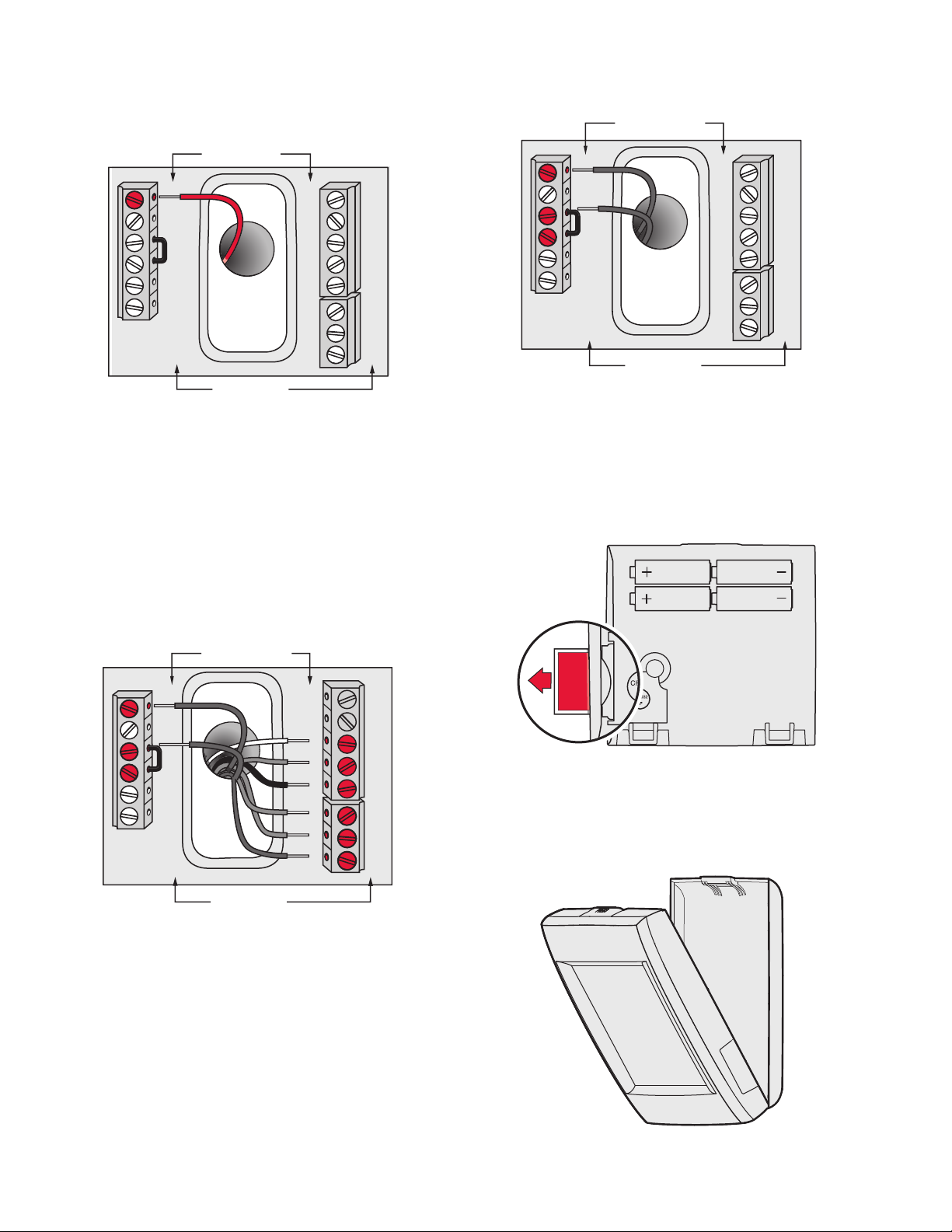
2. For 24VAC primary power, connect common side of
transformer to C terminal.
Fig. 20. Inserting wires in thermostat terminal block.
Fig. 18. Connecting C wire to terminal block.
Wiring the Thermostat
IF THE THERMOSTAT IS WIRED DIRECTLY TO THE
EQUIPMENT
1. Refer to Fig. 19. See Table 10 on page 118 for terminal
designations and “Wiring” beginning on page 117 for
more information.
2. Turn on 24VAC NOW.
NOTE: 24VAC (C wire) is required to connect RedLINK
accessories.
Remove Coin Cell Battery Tab
1. Remove tab to activate coin cell battery.
NOTE: Coin cell battery saves time and date during a
power loss.
INSTALLATION
REMOVE DURING
Fig. 21. Remove coin cell battery tab.
Mounting Thermostat on Wallplate
1. Align thermostat at bottom and snap into place as
shown.
Fig. 19. Thermostat wired directly to equipment.
IF THE THERMOSTAT IS USED WITH AN EQUIPMENT
INTERFACE MODULE OR TRUEZONE WIRELESS
ADAPTER
1. Power the thermostat using Rc and C terminals or with
batteries. Refer to Fig. 20.
NOTE: The relay outputs and inputs on the thermostat
68-0312—03 12
do not function when used with an Equipment
Interface Module or TrueZONE Wireless
Adapter.
Fig. 22. Mount thermostat.

POWER OPTIONAL REDLINK™
THM4000R1000
TrueSTEAM
MCR31476
6
543
2
ON
OFF
1
MCR33269
ACCESSORIES
Outdoor air sensor
1. Install 2 fresh AA lithium batteries.
VISIONPRO® 8000 WITH REDLINK™
M32940
Fig. 26.
MCR32937
Fig. 23.
Portable Comfort Control
1. Install 3 fresh AA alkaline batteries.
MCR32939
Fig. 24.
Indoor air sensor
1. Install 2 fresh AAA alkaline batteries.
TrueSTEAM
1. Wire and power TrueSTEAM.
2. Connect the ABCD terminals between TrueSTEAM and
the THM4000 Wireless Adapter.
3. Adjust the DIP Switches on TrueSTEAM as follows when
using the Wireless Adapter:
•DIP3: UP
•DIP4: UP
•DIP5: DOWN
RedLINK™ Internet Gateway
MCR32938
Fig. 25.
1. Connect power cord to an electrical outlet not controlled
by a wall switch.
2. Connect ethernet cable to router and the RedLINK Internet Gateway.
Fig. 27. Powering TrueSTEAM wireless adapter.
Entry/Exit Remote or Vent Boost Remote
1. Remove the cover.
2. Insert the CR2450 coin cell battery (included) into the
slot at the bottom of the remote. See polarity marking on
the remote.
Fig. 28. Installing Entry/Exit Remote or Vent Boost Remote
battery.
3. The LED will briefly flash green. If it flashes red, battery
is not good.
13 68-0312—03
VISIONPRO® 8000 WITH REDLINK™
APPLICATION
residential
CONNECT
CONNECTED
MCR33970
Connect RedLINK
Accessories?
PERFORMING INITIAL SETUP
NOTE: If the thermostat is wired directly to the equip-
ment, 24 VAC (C wire) is required to connect
RedLINK accessories. Turn on 24 VAC before performing the initial setup.
Initial setup options define the type of system you are installing:
• Residential or commercial
• Non-zoned or zoned
• Used with or without an Equipment Interface Module
(THM5421)
• Used with or without the TrueZONE Wireless Adapter
(THM4000)
1. Follow prompts on the screen to select the appropriate
options.
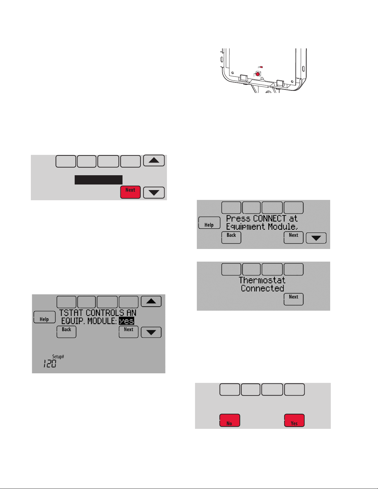
Fig. 31. EIM CONNECT button.
NOTE: If the “Connected” light does NOT flash green,
another system may be in the listening mode.
Please exit the listening mode at the other system and then try again.
Green Flashing: In Listening Mode - system is
ready to add RedLINK devices.
Green Steady: RedLINK devices are communicating.
Red: RedLINK device(s) are NOT communicating. Check EIM and RedLINK devices.
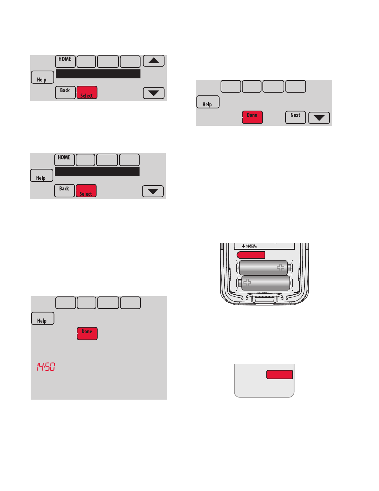
3. While the “Connected” light is flashing green on the EIM,
press Next on the thermostat. After a short delay, the
screen will show the thermostat is connected.
Fig. 29. Select application (residential or commercial).
NOTE: If you are connecting the thermostat to the True-
ZONE Wireless Adapter (THM4000), refer to the
TrueZONE instructions to link the thermostat and
RedLINK accessories.
Linking Thermostat to Equipment Interface Module (if used)
1. In thermostat setup, when you are prompted to answer
TSTAT CONTROLS AN EQUIP. MODULE: select yes,
then press Next.
Fig. 30.
Fig. 32.
Fig. 33.
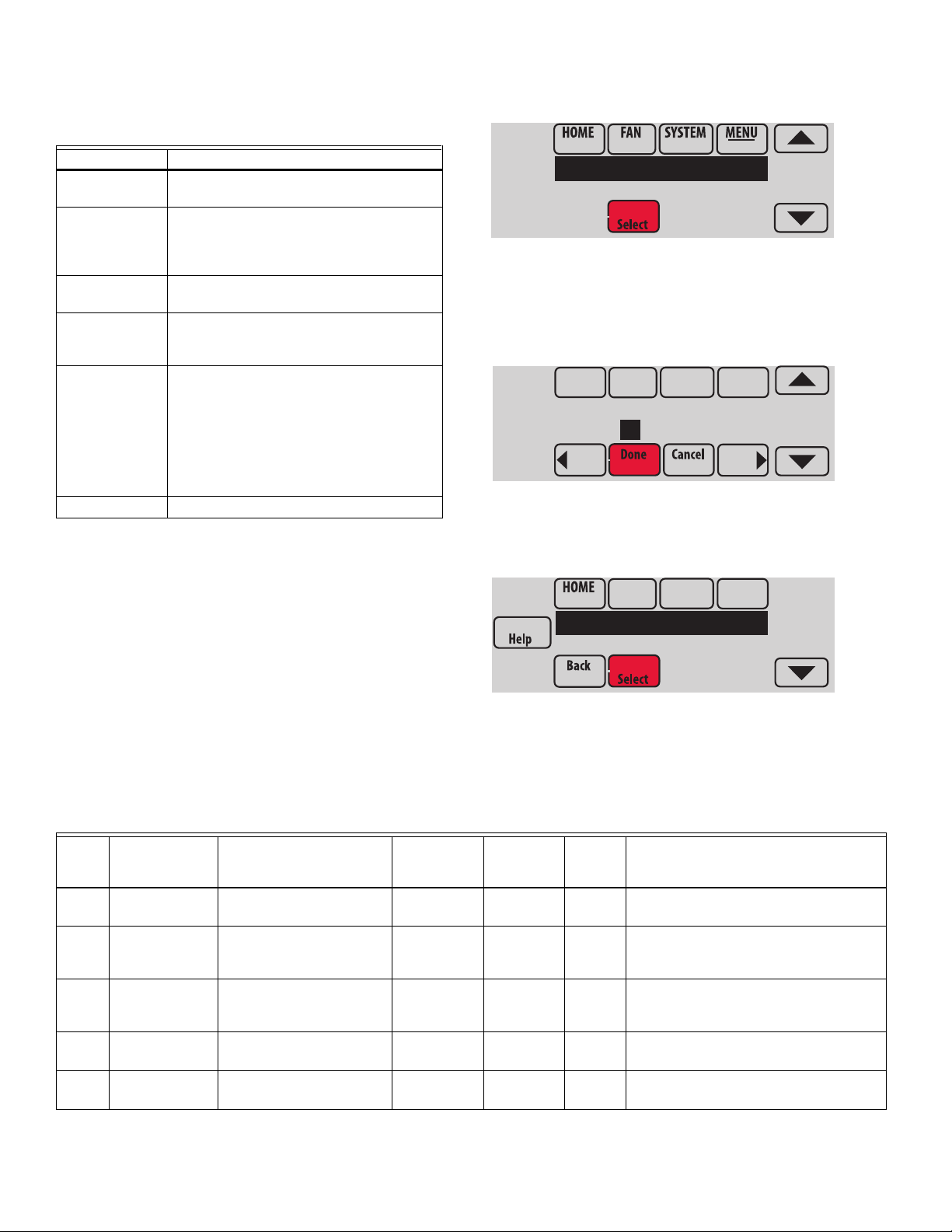
4. Press Next, as directed on screen, to link RedLINK
accessories.
Linking RedLINK Accessories
1. When you see the prompt Connect RedLINK Accesso-
ries?, touch No or Yes.
a. If you select No, continue to step 5.
b. If you select Yes, you will be prompted to Press Con-
nect on New Accessories. Continue to step 2.
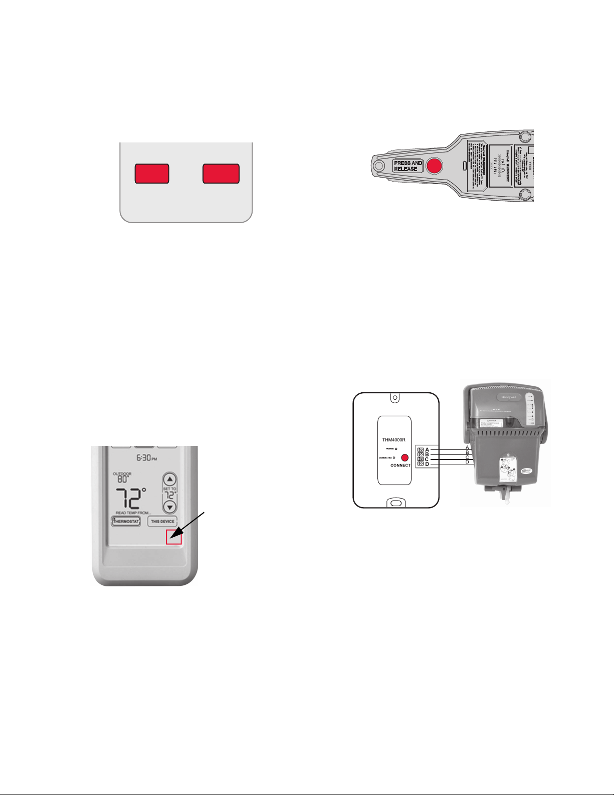
2. Press and quickly release the CONNECT button on the
EIM. Make sure the “Connected” light is flashing green.
68-0312—03 14
Fig. 34. Connect RedLINK accessories.
NOTE: Accessories must be at least 2 feet away from the
thermostat or EIM during the linking process.
VISIONPRO® 8000 WITH REDLINK™
Press Connect on
New Accessories.
MCR33972
Outdoor Sensor
has been added
M34150
THERMOSTAT TYPE
programmable
MCR33976
Installer Options
MCR33977
Enter password
0 0 0 0
2. While the Press Connect message is displayed (listening
mode), press and quickly release the CONNECT button
on each new RedLINK accessory.
NOTE: For locations of CONNECT buttons on
RedLINK accessories, see “Locating the Connect Buttons on RedLINK Accessories” beginning on page 16.
Fig. 35. Thermostat in listening mode.
3. After a short delay (up to 15 seconds), check thermostat
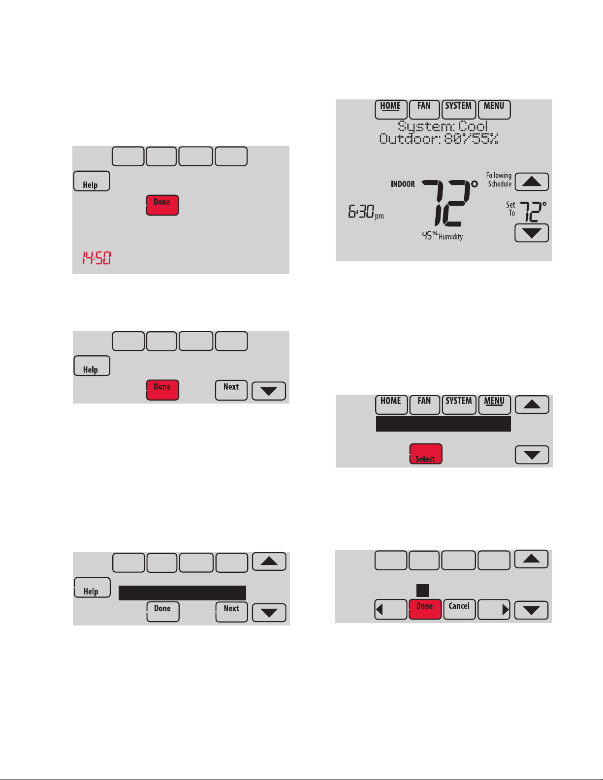
to confirm the connection of each RedLINK accessory.
Touch or to review the list.
The thermostat now displays its Home screen and the
thermostat setup is complete.
M33985
Fig. 38. Thermostat home screen.
Adding RedLINK Accessories to the Thermostat
If you want to add RedLINK accessories after the thermostat
has been setup, follow these steps.
Fig. 36. Outdoor sensor added.
4. Touch Done at the thermostat after all new RedLINK
accessories are connected.
NOTE: Thermostat displays a countdown timer while in
the listening mode. If it detects no activity for 15
minutes, it exits listening mode.
Completing Initial Setup
5. Finish the setup by selecting the desired options. Touch
Done after you select the last option you want to change.
Fig. 37. Thermostat type.
1. Touch Menu.
2. Select Installer Options.
Fig. 39.
3. Enter password (date code) and touch Done. See “Find-
ing Your Password (Date Code) to Access Installer
Options” beginning on page 19 for more information.
Fig. 40.
15 68-0312—03
VISIONPRO® 8000 WITH REDLINK™
MCR33980
Wireless Manager
Reset To Defaults
MCR33981
Add Device
Connected Devices
MCR34058
Press Connect on
New Accessories.
MCR33972
Outdoor Sensor
has been added
MCR28847A
4. Select Wireless Manager.
Fig. 41.
5. Select Add Device. The screen displays “Press Connect
on New Accessories.” The thermostat is now in listening
mode.
Fig. 42.
NOTE: Accessories must be at least 2 feet away from the
thermostat or EIM during the linking process.
7. After a short delay (up to 15 seconds), check thermostat
to confirm the connection of each RedLINK accessory.
Touch or to review the list.
8. Touch Done at the thermostat after all new RedLINK
accessories are connected.
Fig. 44.
NOTE: Thermostat displays a count-down timer while in
the listening mode. If it detects no activity for 15
minutes, it exits listening mode.
Locating the Connect Buttons on RedLINK Accessories
Wireless Outdoor Sensor
1. Press and quickly release the CONNECT button on the
Wireless Outdoor Sensor. After a short delay (up to 15
seconds), the thermostat will display “Outdoor Sensor
has been added.”
6. Press and quickly release the CONNECT button on each
new RedLINK accessory.
NOTE: For locations of CONNECT buttons on
RedLINK accessories, see “Locating the Connect Buttons on RedLINK Accessories” beginning on page 16.
Fig. 43. Thermostat in listening mode.
Fig. 45. Wireless outdoor sensor connect button.
Portable Comfort Control
1. Press CONNECT on the Portable Comfort Control dis-
play screen.
CONNECT
WIRELESS SETUP
MCR32942
Fig. 46. Portable Comfort Control connect button.
2. Press DONE on the Portable Comfort Control when it
displays “Connected.”
68-0312—03 16
VISIONPRO® 8000 WITH REDLINK™
NOYES
CONNECT MORE?
M28482
Press and hold
the blank space
(or arrow may be
present)
MCR32943
3. Press “No” at the next screen to save and exit, or press
“Yes” if you need to connect additional thermostats to the
Portable Comfort Control. See Fig. 47.
NOTE: The Portable Comfort Control can control up to 16
thermostats.
Fig. 47. Connect additional thermostats to Portable
Comfort Control.
4. Follow the same linking procedure as above to connect
additional thermostats.
ERROR MESSAGES:
E1 29: Incompatible device cannot be connected.
E1 34: Low RF signal. Move device to a different location and
try again.
E1 38: Make sure the thermostat, EIM, or TrueZONE Wireless
Adapter is in Wireless Setup mode, and the Portable Comfort
Control is at least 2 feet away (600 mm).
NOTE: The linking procedure will time out if there is no
keypress for 30 minutes. To begin again, press
and hold in the lower right corner of the screen
until the display changes (about 3 seconds). See
Fig. 48.
RedLINK Internet Gateway
1. Press and quickly release the button on the bottom of the
Internet Gateway. After a short delay, the RedLINK status light will glow steady green.
Fig. 49. RedLINK Internet Gateway connect button.
NOTE: The Internet Gateway must be registered online
before use at www.mytotalconnectcomfort.com.
Enter the MAC ID and MAC CRC numbers located
on the bottom of the Internet Gateway. For additional information, see instructions provided with
the device.
TrueSTEAM
1. Press and quickly release the CONNECT button on
THM4000 Wireless Adapter. After a short delay, the
CONNECTED status light will glow steady green.
TrueSTEAM
THM4000R1000
Fig. 48. Restarting the linking process.
MCR34523
Fig. 50. Connect button on TrueSTEAM wireless adapter.
17 68-0312—03
VISIONPRO® 8000 WITH REDLINK™
MCR32934
MCR32935
MCR33096
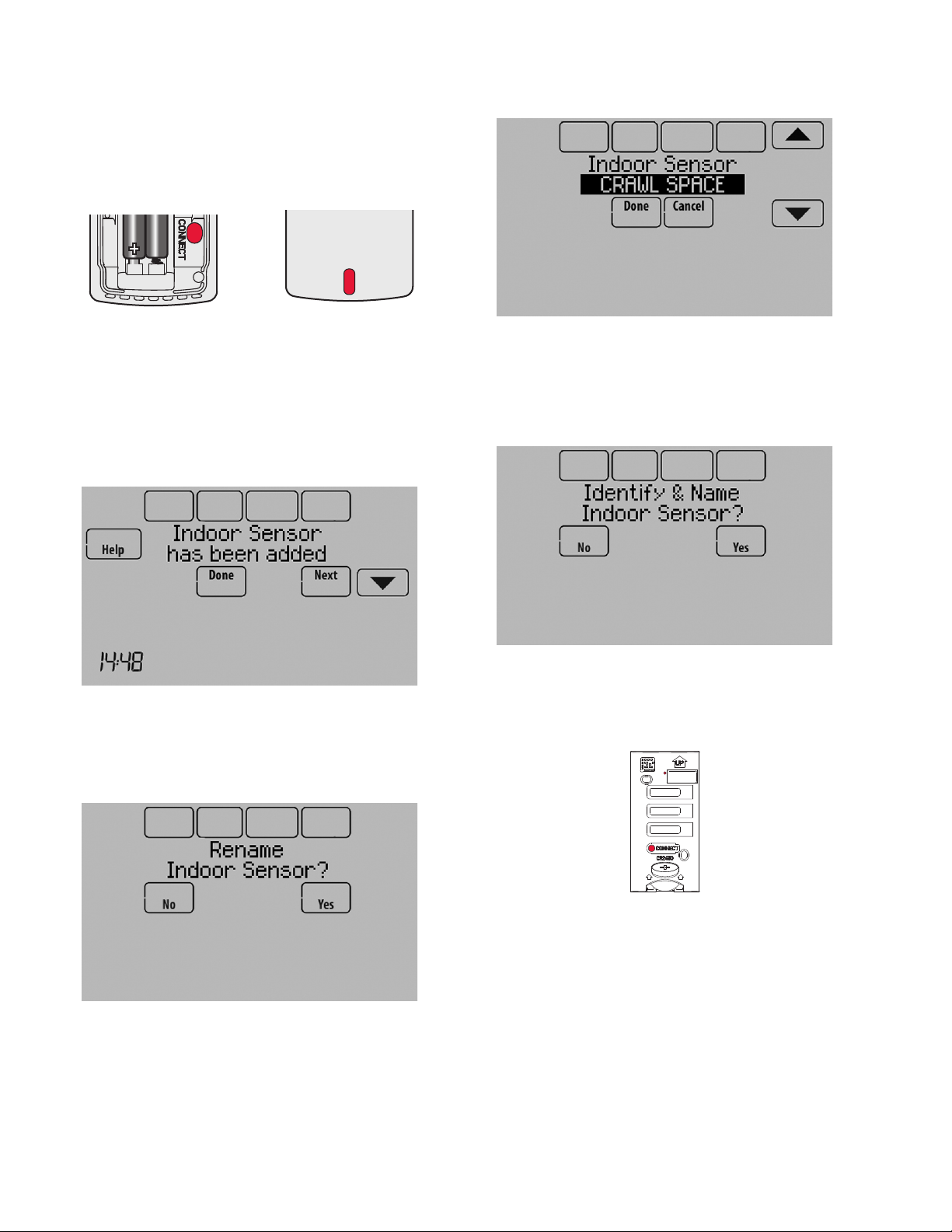
Wireless Indoor Sensor
1. Press and quickly release the CONNECT button. After a
short delay, the status light (see Fig. 51) will glow green
for 15 seconds. If the status light turns red, the sensor
did not link with the thermostat.
Fig. 51. Wireless indoor sensor connect button and status
light.
NOTE: In normal operation, the status light remains off.
If it begins flashing red, batteries are low (power
will be depleted after 2–3 weeks).
2. After a short delay (up to 15 seconds), check thermostat
to confirm the connection of the sensor.
Fig. 52.
3. If you are installing more than 1 wireless indoor sensor,
give each sensor a name as you install it. Press Yes
when the “Rename Indoor Sensor?” screen is displayed,
as shown in Fig. 53.
Fig. 54.
NOTE: If you link more than 1 wireless indoor sensor,
and forget to name them, you will be prompted
to name each wireless indoor sensor after you
exit wireless setup. See Fig. 55.
Fig. 55.
Entry/Exit Remote or Vent Boost Remote
1. Press and quickly release the CONNECT button.
Fig. 53.
4. Select the Indoor Sensor name from the list and press
Done. The Indoor Sensor names are used when selecting which sensor to use for temperature control, humidification control, and dehumidification control.
68-0312—03 18
Fig. 56. Connect button and status light on Entry/Exit
Remote or Vent Boost Remote.
2. After a short delay, the status light will glow green for 15
seconds. If the status light turns red, the remote did not
link with the thermostat for the connection process.
NOTE: The thermostat can work with up to 3 Entry/Exit
remotes. Each Entry/Exit remote can control up to
16 thermostats.
NOTE: The thermostat can work with up to 6 Vent Boost
remotes.
VISIONPRO® 8000 WITH REDLINK™
MCR34022
Dealer Information
Installer Options
MCR33975
TH8321R1001
Date Code: 1324
Residential/Résidentiel
1-800-468-1502
http://yourhome.honeywell.com
Commercial/Commerciale
1-888-245-1051
http://customer.honeywell.com
Honeywell, Golden Valley, MN 55422
RoHs Compliant
Conformité RoHs
Assembled in Mexico
Assemblé au Mexique
TH8321R1001
1
1324
Password
(Date Code)
Scroll to see:
Installer Setup
Installer Test
Data Logs
Wireless Manager
Reset To Defaults
Device Info
Finding Your Password (Date Code) to Access Installer Options
You need a password (Date Code) to access Installer Options.
Installer Options allow you to:
• Make changes to the Installer Setup.
• Perform an Installer Test.
• Add, remove, rename or view connected RedLINK
accessories.
• Reset the thermostat to Factory Default settings.
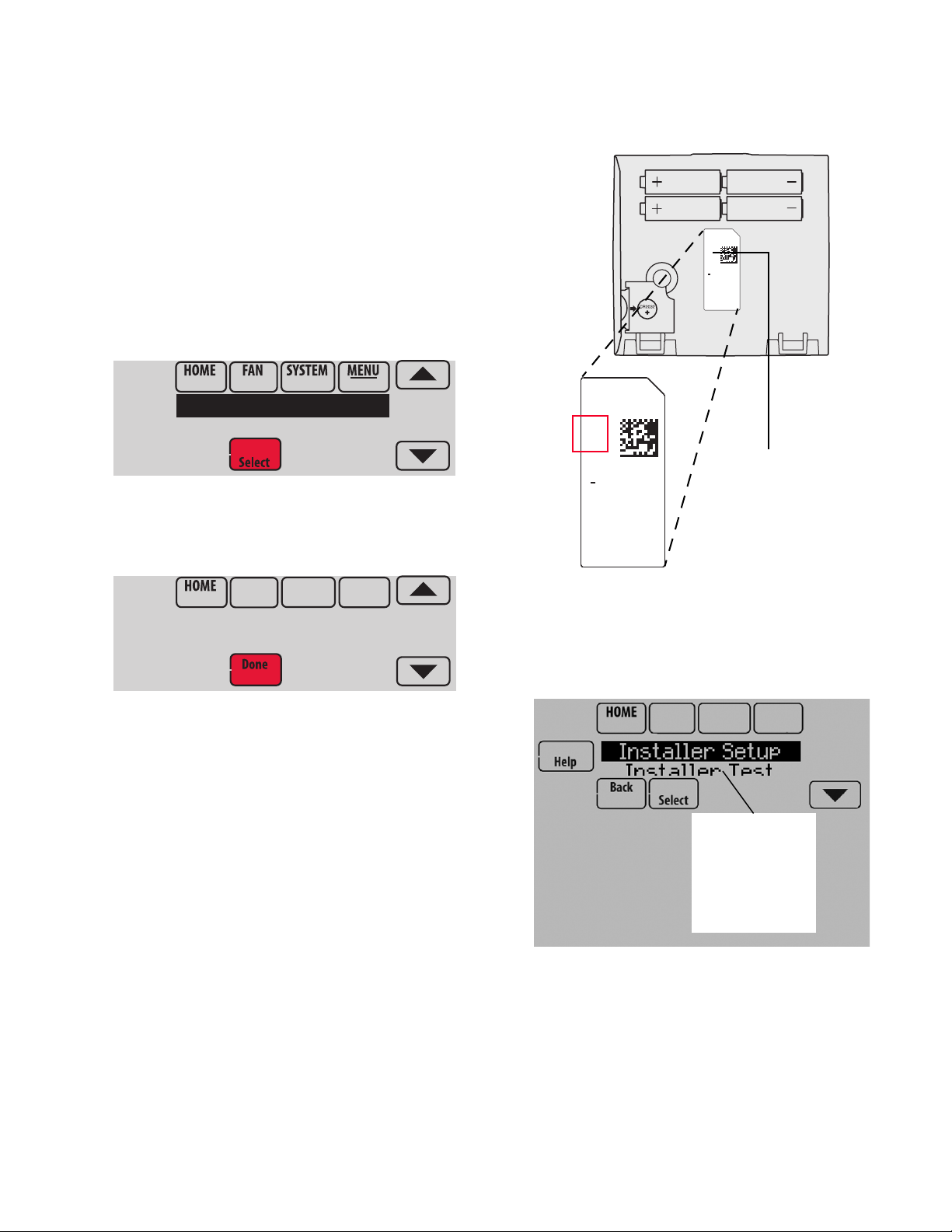
The password (Date Code) is located on the back of the
thermostat. It can also be found by following these steps:
1. Touch Menu.
2. Select Dealer Information.
Fig. 57.
3. Scroll down to see the Date Code.
Thermostat Password (Date Code)
RoHs Compliant
Conformité RoHs
Assembled in Mexico
Assemblé au Mexique
1324
1
TH8321R1001
Residential/Résidentiel
1-800-468-1502
http://yourhome.honeywell.com
Commercial/Commerciale
1-888-245-1051
http://customer.honeywell.com
Honeywell, Golden Valley, MN 55422
Fig. 59. Locate password.
The following options are available when you access Installer
Options. For more information on each, press Help on the
thermostat or see Table 1.
Fig. 58.
Fig. 60.
19 68-0312—03
VISIONPRO® 8000 WITH REDLINK™
MCR33976
Installer Options
MCR33977
Enter password
0 0 0 0
MCR34015
Installer Setup
Installer Test
Table 1. Installer Options.
Menu Item Description
Installer Setup Select INSTALLER SETUP to set system
Installer Test Select INSTALLER TEST to quickly
Data Logs Select DATA LOGS to turn off/on the Alerts
Wireless
Manager
Reset To
Defaults
Device Info For Honeywell use only.
NOTE: You can use the thermostat microSD port to
download all Installer Setup settings, including
your company name and contact information. You
can upload this data to each thermostat you
install, to save time.
settings one by one.
determine if the heat, cool, fan and
thermostat are operating properly. Minimum
off timers are ignored during the test.
Log or Interaction Log.
Select WIRELESS MANAGER to add,
remove, rename or view the connected
wireless accessories.
Select RESET TO DEFAULTS to place all
thermostat settings back to the factory
settings.
Note: If the thermostat has been setup
WITHOUT an Equipment Interface Module
or the TrueZONE Wireless Adapter and you
would like to add one, you must reset the
thermostat back to factory defaults.
Fig. 61.
3. Enter password (date code) and touch Done. See “Find-
ing Your Password (Date Code) to Access Installer
Options” beginning on page 19 for more information.
Fig. 62.
4. Select Installer Setup.
Make Changes to Installer Setup
NOTE: Use a microSD card to save set up time. See “To
Number
101 Application
102 Zone Number
103 Thermostat Name
104 Thermostat Type
105 Temperature Scale
Use the MicroSD Card in the Thermostat” on
page 101.
1. Touch Menu.
2. Select Installer Options.
ISU
Installer Setup
Name Settings Default
Residential
Commercial
1-16
[Select Thermostat Name]
Non-Programmable
Programmable
Fahrenheit
Celsius
Table 2. Installer Setup (ISU) Table.
Residential Both No
1 Both No This ISU is only displayed on a thermostat
Thermostat Both No The Portable Comfort Control remote and
Programmable Both No
Fahrenheit Both No
Fig. 63.
5. Follow prompts on the screen to select the desired setup
options. See Table 2 for Installer Setup options.
Residential,
Commercial
or Both
Requires
EIM Notes
that is controlling a zone panel through the
THM4000 Wireless.
Web Interface displays the name of the
thermostat that you enter on this screen.
68-0312—03 20

Table 2. Installer Setup (ISU) Table. (Continued)
VISIONPRO® 8000 WITH REDLINK™
ISU
Number
Installer Setup
Name Settings Default
106 Outdoor Air
Sensor
200 Heating System
201 Heating
Equipment
203 Radiant Stage 1
No
Yes
Conv. Forced Air
Heat Pump
Radiant Heat
Other
None (Cool Only)
Heat Pump:
Air to Air Heat Pump
Geothermal
Geothermal Radiant
None
U1
U2
U3
Residential,
Commercial
or Both
Requires
EIM Notes
No Both No This ISU automatically defaults to Yes when a
Wireless Outdoor Sensor is connected.
An Outdoor Sensor is required to set the
following ISUs:
ISU 312 Outdoor Temperature Lockouts (Heat
Pump Lockout and Backup Heat Lockout)
ISU 405 Outdoor Temperature used with
Minimum Heat Recovery Ramp Rate
ISU 406 Outdoor Temperature used with
Maximum Heat Recovery Ramp Rate
ISU 407 Outdoor Temperature used with
Minimum Cool Recovery Ramp Rate
ISU 408 Outdoor Temperature used with
Maximum Cool Recovery Ramp Rate
ISU 805 Humidification - Window Protection
ISU 1013 Low Outdoor Temperature
Ventilation Lockout
ISU 1013 High Outdoor Temperature
Ventilation Lockout
ISU 1013 High Outdoor Dew Point Ventilation
Lockout (requires Wireless Outdoor Sensor)
Conv. Forced
Both No
Air
Air to Air Heat
Pump
Both No This ISU is not displayed when ISU 200
Heating System is set to Conv. Forced Air,
Radiant Heat, Other or None (Cool Only).
See “Geothermal Radiant Heat” beginning on
page 78.
Default varies
based on
Both No This ISU is only displayed when ISU 201
Heating Equipment is Geothermal Radiant.
previous
selections
Geothermal Radiant Heat must be wired to a
universal terminal (U1, U2, or U3).
204 Radiant Stage 2
None
U1
U2
U3
Default varies
based on
previous
selections
21 68-0312—03
U1, U2 and U3 are normally open dry contacts
when configured for a stage of Heat. U1, U2
and U3 require power from the system
transformer or a separate transformer.
U2 and U3 are only available on the
Equipment Interface Module (EIM).
Both No This ISU is only displayed when ISU 201
Heating Equipment is Geothermal Radiant.
Geothermal Radiant Heat must be wired to a
universal terminal (U1, U2, or U3).
U1, U2 and U3 are normally open dry contacts
when configured for a stage of Heat. U1, U2
and U3 require power from the system
transformer or a separate transformer.
U2 and U3 are only available on the
Equipment Interface Module (EIM).

VISIONPRO® 8000 WITH REDLINK™
Table 2. Installer Setup (ISU) Table. (Continued)
ISU
Number
Installer Setup
Name Settings Default
205 Geo Forced Air
206 Reversing Valve
207 Cool Stages /
Compressor
Stages
None
Cooling Only
Heating and Cooling
O (O/B on Cool)
B (O/B on Heat)
1-4
Residential,
Heating and
Cooling
Commercial
or Both
Both No This thermostat has the capability of
Requires
EIM Notes
controlling Geothermal Radiant Heat,
Geothermal Forced Air and Backup Heat.
If this thermostat is not controlling the
Geothermal Forced Air System, select None.
This setting is typically used if the thermostat
is only controlling Geothermal Radiant Heat.
If this thermostat is using the Geothermal
Forced Air System for cooling and not for
heating, select Cooling Only.
If this thermostat is using the Geothermal
Forced Air System for both heating and
cooling, select Heating and Cooling.
O/B on Cool Both No Only displayed if the equipment type is Air to
Air Heat Pump, Geothermal or Geothermal
Radiant.
1 if ISU 101 is
Residential
Both No Conventional:
Cool Stage 3 and 4 are only available if ISU
101 is Commercial.
2 if ISU 101 is
Commercial
Cool Stage 3 and 4 must be wired to a
universal terminal (U1, U2 or U3).
202,
207
Heat Stages /
Backup Heat
Stages
208 Cool Stage 3
1 - 3
None
U1
U2
U3
Default is 1
stage if ISU
101 Application
is Residential
Default is 2
stages if ISU
101 Application
is Commercial
Default varies
based on
previous
selections
Heat Pumps:
Maximum of 2 Compressor Stages for heat
pump systems.
Both No Maximum of 3 Heat Stages for conventional
systems.
Maximum of 2 Backup Heat Stages for
systems with more than 1 heating equipment
type.
Commercial No Cool Stage 3 is only available if ISU 1010 is
Commercial.
Cool Stage 3 must be wired to a universal
terminal (U1, U2 or U3).
U1, U2 and U3 are normally open dry contacts
when configured for a stage of Cool. U1, U2
and U3 require power from a system
transformer or a separate transformer.
U2 and U3 are only available on the
Equipment Interface Module (EIM).
68-0312—03 22

Table 2. Installer Setup (ISU) Table. (Continued)
VISIONPRO® 8000 WITH REDLINK™
ISU
Number
Installer Setup
Name Settings Default
209 Cool Stage 4
210 Heat Stage 3
211 Fan Control in
Heat
212 Backup Heat Type
None
U1
U2
U3
None
U1
U2
U3
No Fan
Equip Controls Fan
Tstat Controls Fan
None
Electric
Gas/Oil
Residential,
Default varies
based on
Commercial
or Both
Commercial Yes Cool Stage 4 is only available if ISU 101 is
Requires
EIM Notes
Commercial.
previous
selections
Cool Stage 4 must be wired to a universal
terminal (U1, U2 or U3).
U1, U2 and U3 are normally open dry contacts
when configured for a stage of Cool. U1, U2
and U3 require power from a system
transformer or a separate transformer.
U2 and U3 are only available on the
Equipment Interface Module (EIM).
Default varies
based on
previous
selections
Both No TH8321 Thermostat Only:
This ISU is only displayed on the TH8321
thermostat when it is wired directly to the
equipment (Equipment Interface Module is
NOT used).
Heat Stage 3 must be wired to a universal
terminal (U1).
U1 is a normally open dry contact when
configured for a stage of Heat. U1 requires
power from a system transformer or a
separate transformer.
Equip Controls
Fan
Both No No Fan is only displayed when ISU 201
Heating Equipment is Other.
None Both No This ISU is only displayed when ISU 201
Heating Equipment is Radiant Heat or Other.
When ISU 201 Heating Equipment is Radiant
Heat, the thermostat keeps the Radiant Heat
on when it calls for Backup Heat.
213 Backup Heat
Stages
214 Backup Heat Stg 2
0 - 2
None
U1
When ISU 201 Heating Equipment is Other,
you can select how the backup operates. See
ISU 215.
1 Both No This ISU is only displayed when a backup heat
source is selected at ISU 212 Backup Heat
Type.
Maximum of 2 Backup Heat stages.
Default varies
based on
previous
selections
Both No TH8321 Thermostat Only:
This ISU is only displayed on the TH8321
thermostat when it is wired directly to the
equipment (Equipment Interface Module is
NOT used).
The thermostat can support up to 3
conventional heat stages. When there are a
total of 3 conventional heat stages, the last
stage of heat must be wired to U1.
U1 is a normally open dry contact when
configured for a stage of Heat. U1 requires
power from a system transformer or a
separate transformer.
23 68-0312—03

VISIONPRO® 8000 WITH REDLINK™
Table 2. Installer Setup (ISU) Table. (Continued)
ISU
Number
Installer Setup
Name Settings Default
215 Run Backup Heat
with Primary
216 Backup Heat Fan
217 Backup Heat
Stage 2
No
Yes
Equip Controls Fan
Tstat Controls Fan
None
U1
Residential,
Commercial
or Both
Requires
EIM Notes
No Both No This ISU is only displayed when ISU 201
Heating Equipment is Other.
When ISU 201 Heating Equipment is Other,
you can select how the Backup Heat operates.
The thermostat can be setup to keep the
primary heat source on when it calls for
Backup Heat or the thermostat can be setup to
turn off the primary heat source when it calls
for Backup Heat.
When ISU 201 Heating Equipment is Radiant
Heat, the thermostat keeps the Radiant Heat
on when it calls for Backup Heat.
Tstat Controls
Fan
Both No This ISU is only displayed for conventional
systems when ISU 212 Backup Heat Type is
Electric.
Backup Heat Fan Operation automatically
defaults to Equip Controls Fan when ISU 212
Backup Heat Type is Gas/Oil.
Default varies
based on
previous
selections
Both No TH8321 Thermostat Only:
This ISU is only displayed on the TH8321
thermostat when it is wired directly to the
equipment (Equipment Interface Module is
NOT used).
218 Backup Heat Type
219 External Fossil
Fuel Kit
Electric
Gas/Oil
No
Yes
The thermostat can support up to 2 backup
heat stages for heat pump applications. When
there are 2 backup heat stages, backup heat
stage 2 must be wired to U1.
U1 is a normally open dry contact when
configured for a stage of Heat. U1 requires
power from a system transformer or a
separate transformer.
Electric Both No This ISU is only displayed when ISU 201
Heating Equipment is Air to Air Heat Pump,
Geothermal or Geothermal Radiant and there
is at least one stage of backup heat.
See “Heat Pump and Backup Heat Operation”
beginning on page 78.
No Both No This ISU is only displayed when ISU 201
Heating Equipment is Air to Air Heat Pump,
Geothermal or Geothermal Radiant and ISU
218 Backup Heat Type is Gas/Oil.
68-0312—03 24

Table 2. Installer Setup (ISU) Table. (Continued)
VISIONPRO® 8000 WITH REDLINK™
ISU
Number
Installer Setup
Name Settings Default
222 A-L/A Terminal
None
Time Of Day
Economizer
Heat Pump Fault
Residential,
Commercial
or Both
Requires
EIM Notes
None Commercial No This ISU is only displayed when ISU 101
Application is Commercial.
Note: When the thermostat is setup for
Residential, the L/A terminal operates as
described under "Heat Pump Fault". The L/A
terminal requires no setup for residential
applications.
None: The A-L/A terminal is not used.
Time of Day: The A-L/A terminal is energized
during Occupied periods and when the user
overrides the temperature. The terminal is de-
energized during Unoccupied periods and in
Standby mode.
Economizer: The thermostat controls an
economizer module to provide ventilation
during Occupied periods and free cooling
when outdoor conditions are favorable. The
A-L/A terminal is energized during Occupied
periods and during a call for cooling in
Unoccupied periods. See “Economizer and
Time of Day (TOD) Operation” beginning on
page 106.
Notes: The economizer module determines
when outdoor conditions are favorable for free
cooling.
300 System
Changeover
Manual
Automatic
Manual:
if ISU 101 is
Residential
Automatic:
if ISU 101 is
Commercial
Heat Pump Fault: When 24 volts is detected
on the L/A terminal (compressor monitor), the
thermostat displays a message to alert the
user when the heat pump requires service.
The L/A terminal sends a continuous output to
a zone panel when the thermostat is set to
Emergency Heat mode. The zone panel will
not turn on the heat pump when a zone is set
to Emergency Heat mode.
Both No Manual: The user must select heating or
cooling as needed to maintain the desired
indoor temperature.
Automatic: The user has the option to select
Auto for the system setting. In Auto mode, the
thermostat controls heating and cooling
equipment as needed to maintain the desired
indoor temperature.
25 68-0312—03

VISIONPRO® 8000 WITH REDLINK™
Table 2. Installer Setup (ISU) Table. (Continued)
ISU
Number
Installer Setup
Name Settings Default
300 Auto Changeover
Deadband
301 Control Options
2° F to 9° F (in 1° F increments)
Basic Options
Advanced Options
Residential,
Commercial
or Both
Requires
EIM Notes
3° F Both No This ISU is only displayed when ISU 300 is set
to Automatic.
Deadband is the minimum separation between
heat and cool settings when the thermostat is
setup for Auto Changeover. For example, if the
deadband is set to 3° F and the cool setpoint
is 75° F, the warmest heat setpoint allowed
would be 72° F. If the heat setpoint is adjusted
above 72° F, it will automatically adjust the
cooling setpoint higher to maintain the 3° F
deadband.
When ISU 907 or ISU 910 (Dehum Over
Cooling Limit) is set to 1, 2, 3, 4 or 5 F, the
thermostat will not show the full Deadband
range. For example, if you set a Deadband of 3
F and an Over Cooling Limit of 2 F, the
minimum Deadband that you can select will
be 5 F. This prevents the heating system from
turning on when the thermostat over cools to
reach the dehumidification setting.
Basic Options Both No Basic Options: The Installer Setup displays
basic temperature control options which
include Backup Heat Droop, Backup Heat
Upstage Timer, Outdoor Temperature
Lockouts and Cycle Rate settings per stage.
302 Finish With High
Cool Stage
302 Finish With High
Heat Stage
No
Yes
No
Yes
Note: Outdoor Temperature Lockouts only
apply to Heat Pump applications.
Advanced Options: The Installer Setup
displays both Basic and Advanced Options.
Advanced temperature control options include
Finish With High Cool Stage, Finish With High
Heat Stage, and Temperature Differential
settings between all stages.
No Both No ISU 301 Control Options must be set to
Advanced to view or adjust Finish With High
Cool Stage.
This ISU is only displayed when the
thermostat is set for 2 or more cool stages.
When set to Yes, this feature keeps the high
stage of the cooling equipment running until
the desired setpoint is reached.
No Both No ISU 301 Control Options must be set to
Advanced to view or adjust Finish With High
Heat Stage.
This ISU is only displayed when the
thermostat is set for 2 or more heat stages.
When set to Yes, this feature keeps the high
stage of the heating equipment running until
the desired setpoint is reached.
68-0312—03 26

Table 2. Installer Setup (ISU) Table. (Continued)
VISIONPRO® 8000 WITH REDLINK™
ISU
Number
Installer Setup
Name Settings Default
303 Cool Differential
Stage 2
303 Cool Differential
Stage 3
303 Cool Differential
Stage 4
Comfort
1.0° F to 3.5° F from setpoint (in
0.5° F increments)
Comfort
1.0°F - 4.0°F from setpoint (in
0.5° F increments)
Comfort
1.0° F to 4.5° F from setpoint (in
0.5° F increments)
Residential,
Commercial
or Both
Requires
EIM Notes
Comfort Both No ISU 301 Control Options must be set to
Advanced to view or adjust this ISU.
This ISU is only displayed when the
thermostat is set to 2 cool stages.
The indoor temperature must rise to the
selected differential setting before the
thermostat turns on the stage of cooling. For
example, if stage 2 is set to 2° F (1.0° C), the
indoor temperature must be 2° F (1.0° C)
away from the setpoint before stage 2 turns
on. When set to Comfort, the thermostat uses
the stage of cooling as needed to keep the
indoor temperature within 1° F (0.5° C)
degree of the setpoint.
Comfort Commercial No ISU 301 Control Options must be set to
Advanced to view or adjust this ISU.
This ISU is only displayed when the
thermostat is set to 3 cool stages.
The indoor temperature must rise to the
selected differential setting before the
thermostat turns on the stage of cooling. For
example, if stage 3 is set to 2° F (1.0° C), the
indoor temperature must be 2° F (1.0° C)
away from the setpoint before stage 3 turns
on. When set to Comfort, the thermostat uses
the stage of cooling as needed to keep the
indoor temperature within 1° F (0.5° C)
degree of the setpoint.
Comfort Commercial Yes ISU 301 Control Options must be set to
Advanced to view or adjust this ISU.
This ISU is only displayed when the
thermostat is set to 4 cool stages.
The indoor temperature must rise to the
selected differential setting before the
thermostat turns on the stage of cooling. For
example, if stage 4 is set to 2° F (1.0° C), the
indoor temperature must be 2° F (1.0° C)
away from the setpoint before stage 4 turns
on. When set to Comfort, the thermostat uses
the stage of cooling as needed to keep the
indoor temperature within 1° F (0.5° C)
degree of the setpoint.
27 68-0312—03

VISIONPRO® 8000 WITH REDLINK™
Table 2. Installer Setup (ISU) Table. (Continued)
ISU
Number
Installer Setup
Name Settings Default
304 Radiant Heat Diff.
Stage 2
305 Heat Differential
Stage 2
Note: Depending
on the application,
the text displayed
on the screen may
show the specific
heating equipment
type
305 Heat Differential
Stage 3
Note: Depending
on the application,
the text displayed
on the screen may
show the specific
heating equipment
type
Comfort
1.0° F to 3.5° F from setpoint (in
0.5° F increments)
Comfort
1.0° F to 3.5° F from setpoint (in
0.5° F increments)
Comfort
1.0° F to 4.0° F from setpoint (in
0.5° F increments)
Residential,
Commercial
or Both
Requires
EIM Notes
Comfort Both No ISU 301 Control Options must be set to
Advanced to view or adjust this ISU.
This ISU is only displayed if ISU 201 Heating
Equipment is Geothermal Radiant and there
are 2 radiant heat stages.
The indoor temperature must drop to the
selected differential setting before the
thermostat will turn on the stage of heating.
For example, if stage 2 is set to 2° F (1.0° C),
the indoor temperature must be 2° F (1.0° C)
away from the setpoint before stage 2 turns
on. When set to Comfort, the thermostat will
use the stage of heating as needed to keep the
indoor temperature within 1° F (0.5° C)
degree of the setpoint.
Comfort Both No ISU 301 Control Options must be set to
Advanced to view or adjust this ISU.
This ISU is only displayed for conventional
systems that have 2 heat stages.
The indoor temperature must drop to the
selected differential setting before the
thermostat will turn on the stage of heating.
For example, if stage 2 is set to 2° F (1.0° C),
the indoor temperature must be 2° F (1.0° C)
away from the setpoint before stage 2 turns
on. When set to Comfort, the thermostat will
use the stage of heating as needed to keep the
indoor temperature within 1° F (0.5° C)
degree of the setpoint.
Comfort Both No ISU 301Temperature Control Options must be
set to Advanced to view or adjust this ISU.
This ISU is only displayed for conventional
systems that have 3 heat stages.
The indoor temperature must drop to the
selected differential setting before the
thermostat will turn on the stage of heating.
For example, if stage 3 is set to 2° F (1.0° C),
the indoor temperature must be 2° F (1.0° C)
away from the setpoint before stage 3 turns
on. When set to Comfort, the thermostat will
use the stage of heating as needed to keep the
indoor temperature within 1° F (0.5° C)
degree of the setpoint.
68-0312—03 28

Table 2. Installer Setup (ISU) Table. (Continued)
VISIONPRO® 8000 WITH REDLINK™
ISU
Number
Installer Setup
Name Settings Default
306 Compressor Heat
Diff. Stage 1
306 Compressor Heat
Diff. Stage 2
Comfort
1.0° F to 4.0° F from setpoint (in
0.5° F increments)
Comfort
1.0° F to 4.5° F from setpoint (in
0.5° F increments)
Residential,
Commercial
or Both
Requires
EIM Notes
Comfort Both No ISU 301 Control Options must be set to
Advanced to view or adjust this ISU.
This ISU is only displayed if ISU 201 Heating
Equipment is Geothermal Radiant and ISU
205 Geo Forced Air is set to Heating and
Cooling.
The indoor temperature must drop to the
selected differential setting before the
thermostat will turn on the stage of heating.
For example, if stage 1 is set to 2° F (1.0° C),
the indoor temperature must be 2° F (1.0° C)
away from the setpoint before stage 1 turns
on. When set to Comfort, the thermostat will
use the stage of heating as needed to keep the
indoor temperature within 1° F (0.5° C)
degree of the setpoint.
Comfort Both No ISU 301 Control Options must be set to
Advanced to view or adjust this ISU.
This ISU is only displayed if ISU 201 Heating
Equipment is Air to Air Heat Pump,
Geothermal or Geothermal Radiant and there
are 2 compressor stages.
308,
309
Backup Heat
Droop Stage 1
Note: “Stage 1" is
not displayed if
there is only 1
stage of Backup
Heat.
Comfort
2.0° F to 15.0° F from setpoint (in
0.5° F increments)
The indoor temperature must drop to the
selected differential setting before the
thermostat will turn on the stage of heating.
For example, if stage 2 is set to 2° F (1.0° C),
the indoor temperature must be 2° F (1.0° C)
away from the setpoint before stage 2 turns
on. When set to Comfort, the thermostat will
use the stage of heating as needed to keep the
indoor temperature within 1° F (0.5° C)
degree of the setpoint.
Comfort Both No A backup heat droop can be set on any system
that has more than one heating equipment
type.
See “Backup Heat Droop” beginning on
page 76.
The Comfort setting is NOT available for Dual
Fuel systems. For example, Heat Pumps with
Gas Forced Air.
29 68-0312—03

VISIONPRO® 8000 WITH REDLINK™
Table 2. Installer Setup (ISU) Table. (Continued)
ISU
Number
308,
309
Installer Setup
Name Settings Default
Backup Heat
Droop Stage 2
311 Upstage Timer for
Backup Heat
312 Outdoor Lockout
Heat Pump
Comfort
2.0° F to 15.5° F from setpoint (in
0.5° F increments)
Off
(30, 45, 60, 75, 90) minutes
(2, 3, 4, 5, 6, 8, 10, 12, 14, 16)
hours
Off
5° F to 60° F (in 5° F increments)
Residential,
Commercial
or Both
Requires
EIM Notes
Comfort Both No ISU 301 Control Options must be set to
Advanced to view or adjust Backup Heat
Droop Stage 2.
This ISU is only displayed if there are 2
backup heat stages.
The indoor temperature must drop to the
selected droop setting before the thermostat
will turn on backup heat stage 2. For example,
if backup heat stage 2 is set to 2° F (1.0° C),
the indoor temperature must be 2° F (1.0° C)
away from the setpoint before backup heat
stage 2 turns on. When set to Comfort, the
thermostat will use backup heat stage 2 as
needed to keep the indoor temperature within
1° F (0.5° C) degree of the setpoint.
Off Both No The Backup Heat Upstage Timer starts when
the highest stage of the previous heating
equipment type turns on. Backup heat will be
used (if needed) when the timer expires. See
“Backup Heat Upstage Timer” beginning on
page 77.
This ISU is only displayed when Backup Heat
Droop Stage 1 is set to 2 F or higher (ISU 308,
309).
Off
Both No ISU 312 Heat Pump Outdoor Lockout requires
an outdoor sensor.
(See Notes)
Default is 40 F if ISU 201 Heating Equipment
is Air to Air Heat Pump and ISU 218 Backup
Heat Type is Gas/Oil.
312 Outdoor Lockout
Backup Heat
Off
5° F to 65° F (in 5° F increments)
Default is Off if ISU 201 Heating Equipment is
Air to Air Heat Pump and ISU 218 Backup
Heat Type is Electric.
Default is Off if ISU 201 Heating Equipment is
Geothermal or Geothermal Radiant.
Heat Pump Outdoor Lockout is optional for
any type of heat pump (Air to Air Heat Pump,
Geothermal Heat Pump or Geothermal
Radiant Heat).
See “Heat pump with outdoor temperature
lockouts” beginning on page 78.
Off Both No ISU 312 Backup Heat Outdoor Temperature
Lockout requires an outdoor sensor.
This ISU is only displayed if ISU 201 Heating
Equipment is Air to Air Heat Pump,
Geothermal or Geothermal Radiant and ISU
219 External fossil fuel kit is set to No.
See “Heat pump with outdoor temperature
lockouts” beginning on page 78.
68-0312—03 30
 Loading...