

Honeywell TH8110, TH8320, TH8321 User Manual
68-0280-01
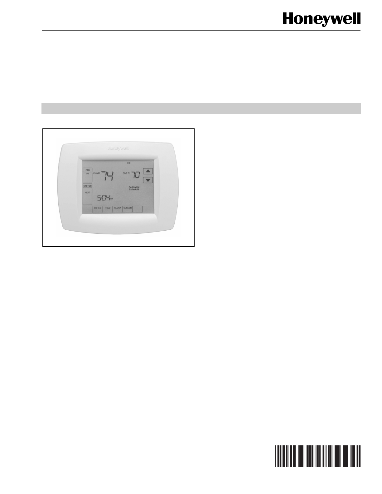
VisionPRO™ 8000 Touchscreen
Programmable Thermostat
APPLICATION
The VisionPRO 8000 Touchscreen Programmable Thermostat
is an effortless, 7-Day programmable thermostat that provides
universal system compatibility, precise comfort control and is
easy-to-program.
PRODUCT DATA
FEATURES
• Large, clear display with backlight shows the current
and set temperature and time—even in the dark.
• Menu-driven programming make setup effortless.
• Beautiful ergonomic design is smart and sophisticated
to match your customers’ lifestyle.
• Touchscreen interaction
• Real-time clock keeps time during power failures and
automatically updates to daylight savings.
• "Saving Changes" notification lets you know when the
schedule changes have been saved.
• Change/check reminders let you know when to service
or replace filters or batteries.
• Various Hold options allow you to override the
program schedule, as desired.
• Speedy same-schedule programming—no need to
copy multiple days.
• Armchair programming allows you to remove the
thermostat from the wall for programming.
• Programmable fan offers increased air quality when
combined with a Honeywell whole-house air cleaner.
The TH8110 Thermostats provide temperature control for gas,
oil, electric and heat pumps for 1 heat, 1 cool systems.
The TH8320 Thermostats provide temperature control for gas,
oil, electric and heat pumps for up to 3 heat, 2 cool systems
including dual fuel operation.
The TH8321 Thermostats provide temperature control for gas,
oil, electric and heat pumps for up to 3 heat, 2 cool systems
including dual fuel operation plus dehumidification control.
® U.S. Registered Trademark
© 2011 Honeywell International Inc.
All Rights Reserved
Contents
Application/Features..........................................................1
Specifications/Ordering Information ..................................2
Installation .........................................................................4
Wiring ................................................................................5
Power the Thermostat .......................................................11
Installer Setup ...................................................................15
Installer System Test .........................................................20
Operation...........................................................................21
Programming.....................................................................23
Troubleshooting.................................................................38
VisionPRO
TM
8000 Touchscreen Programmable Thermostat
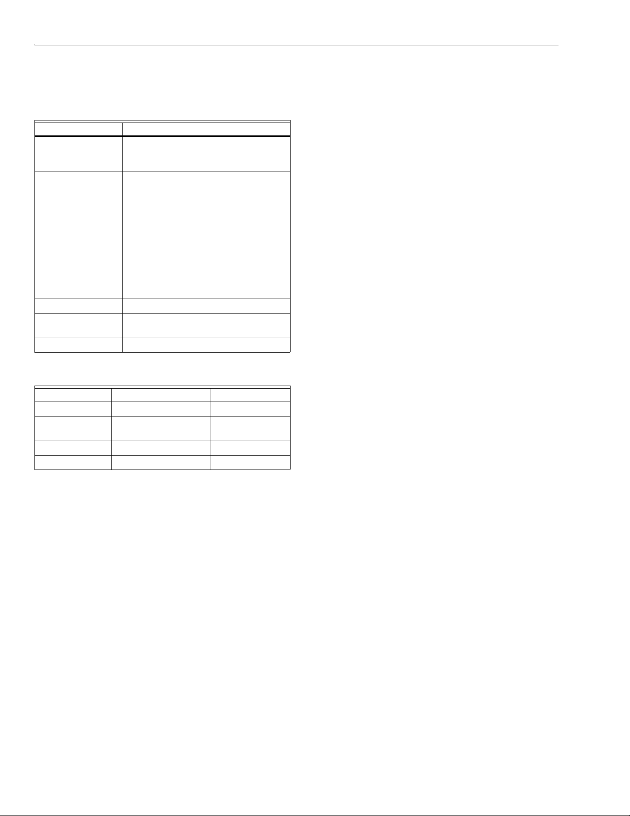
SPECIFICATIONS
Thermostat Description:
Feature Description
Powering methods • Battery only
• Common wire only
• Common wire with battery backup
System types (up to
3 heat/2 cool or up
to 1heat/1cool,
depending on
model)
Changeover Manual or Auto changeover selectable
System setting Heat-Off-Cool-Auto (Em. Heat for heat
Fan setting Auto-On-Circ
Electrical Ratings:
Terminal Voltage (50/60 Hz) Running Current
W Heating 20 - 30 Vac .02 - 1.0A
W Heating
(Powerpile)
Y Cooling 20 - 30 Vac .02 - 1.0A
G Fan 20 - 30 Vac .02 - .60A
Temperature Setting Range:
Heating: 40°F to 90°F(4.5°C to 32°C).
Cooling: 50°F to 99°F (10°C to 37°C).
Operating Ambient Temperature:
TH8000 VisionPRO™ Thermostats: 0°F to 120°F
(-18°C to 49°C).
C7089U: -40°F to 120°F (-40°C to 49°C).
C7189U: 45°F to 88°F (7.2°C to 32°C).
• Gas, oil or electric heat with air
conditioning
• Warm air, hot water, high-efficiency
furnaces, heat pumps, steam and
gravity
• Heat only—includes power to open
and power to close zone valves
(series 20) and normally-open zone
valves
• Heat only with fan
• Cool only
• 750 mV heating systems
pumps)
750 mV dc 100 mA dc
Shipping Temperature:
TH8000 VisionPRO™ Thermostats: -30 °F to 150 °F
(-34.4°C to 65.6°C).
Operating Relative Humidity (Non-condensing):
TH8000 VisionPRO Thermostats: 5% to 90%.
C7089U: 5% to 95%.
C7189U: 5% to 95%.
Humidity Setting Range (TH8321 models only):
Cooling: 40% to 80% RH.
Humidity Display Range (TH8321 models only):
0% to 99%.
Cycle Rates (at 50% Load):
Heating: Selectable 1 - 12 cycles per hour.
Cooling: Selectable 1 - 6 cycles per hour.
Finish:
TH8000 VisionPRO™ Thermostats: Premier White® color.
C7189U Wall Mount Remote Indoor Sensor: Premier White®
color.
Clock Accuracy: +/- 1 minute per month.
Batteries:
Three replaceable AAA alkaline batteries: Power thermostats
when 24 Vac common is not used. Non-replaceable
lithium battery with ten-year life under normal use to hold
calendar and time settings. Alkaline batteries keep calendar and time after lithium battery is no longer functional.
Resistance Characteristics of Remote Sensors:
C7089U Outdoor Sensor: Negative temperature coefficient
(NTC) means that resistance decreases as the
temperature increases. See Table 13 in the Operation
section for sensor resistance characteristics.
C7189U Remote Indoor Sensor: Negative temperature
coefficient (NTC), means that resistance decreases as the
temperature increases. See Table 14 in the Operation
section for sensor resistance characteristics.
Cool Indication:
TH8000 VisionPRO™ Touchscreen Thermostats show "Cool
On" on the screen when Cool is activated.
Heat Indication:
TH8000 VisionPRO™ Touchscreen Thermostats show “Heat
On” on the screen when Heat is activated.
ORDERING INFORMATION
When purchasing replacement and modernization products from your TRADELINE® wholesaler or distributor, refer to the
TRADELINE® Catalog or price sheets for complete ordering number.
If you have additional questions, need further information, or would like to comment on our products or services, please write or
phone:
1. Your local Honeywell Automation and Control Products Sales Office (check white pages of your phone directory).
2. Honeywell Customer Care
1985 Douglas Drive North
Minneapolis, Minnesota 55422-4386
In Canada—Honeywell Limited/Honeywell Limitée, 35 Dynamic Drive, Toronto, Ontario M1V 4Z9.
International Sales and Service Offices in all principal cities of the world. Manufacturing in Australia, Canada, Finland, France,
Germany, Japan, Mexico, Netherlands, Spain, Taiwan, United Kingdom, U.S.A.
68-0280—01 2
Auxiliary Heat Indication:
M22421
6 (152)
THERMOSTAT
4-9/16
(116)
3-3/8 (86)
WALLPLATE
3-3/8 (86)
THERMOSTAT
AND WALLPLATE
1-3/8 (35)
TH8000 VisionPRO™ Touchscreen Thermostats show “Aux.
Heat On” on the screen when Auxiliary Heat is activated.
Emergency Heat Indication:
TH8000 VisionPRO™ Touchscreen Thermostats show “Heat
On” on the screen when Emergency Heat is activated and
the System mode is in the Em. Heat position.
Calibration:
C7089U, C7189U and TH8000 VisionPRO™ Touchscreen
Thermostats are factory-calibrated and require no field
calibration.
Interstage Differential:
TH8000 VisionPRO™ Touchscreen Thermostats operate with
droopless control. Once the thermostat senses that
1st stage is running at 90% capacity, the thermostat
energizes 2nd stage.
Nomenclature:
VisionPRO
TM
8000 Touchscreen Programmable Thermostat
Series
VisionPRO™
8000
Touchscreen
System
Stages Application
11 - 1H/1C
32 - 3H/2C
0 - Standard
1 - Humidity
Sensor
Power and System
Changeover
U - Universal (Auto
changeover and/or
manual changeover) dual powered,
system flexibility,
schedule flexibility.
Mounting Means:
TH8000 VisionPRO™ Touchscreen Thermostat: Mounts
directly on the wall in the living space using mounting
screws and anchors provided. Fits a vertical or horizontal
2 x 4 in. junction box.
C7089U Outdoor Sensor: Mounts outside of living space with
mounting clip and screws provided.
C7189U Remote Indoor Sensor: Mounts directly on the wall
using mounting screws and anchors provided. Fits a
vertical 2 x 4 in. junction box.
Cover Plate:
32003796-001 Cover Plate is used to cover marks left on the
wall by the old thermostat.
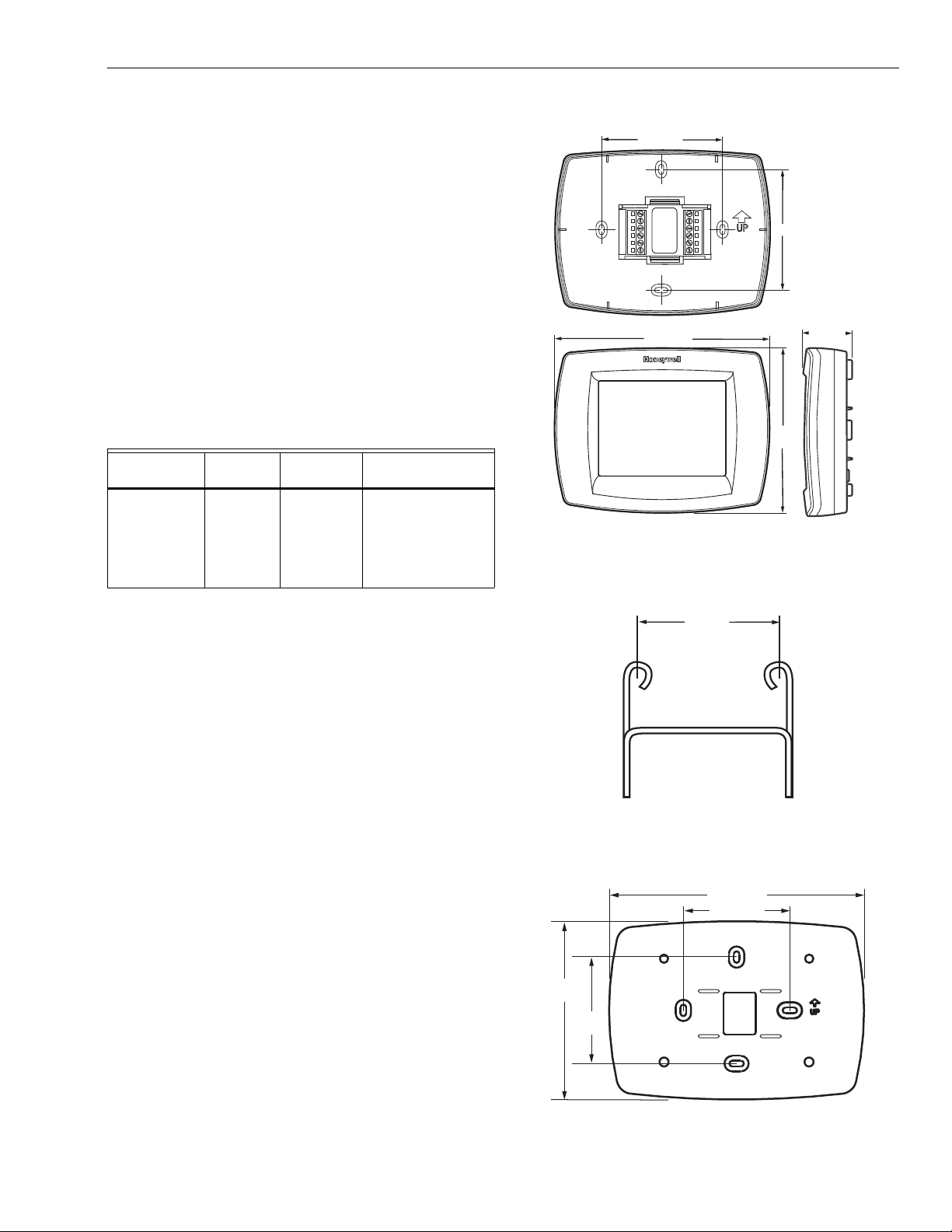
Dimensions:
TH8000 Touchscreen Thermostat: see Fig. 1.
C7089U Outdoor Sensor Mounting Clip: see Fig. 2.
32003796-001 Cover Plate: see Fig. 3.
C7189U Remote Indoor Sensor: see Fig. 4.
Fig. 1. TH8000 Touchscreen Thermostat
dimensions in in. (mm).
1-1/2 (38)
M4488
Fig. 2. C7089U Outdoor Sensor Mounting Clip
dimensions in in. (mm).
7-7/8 (200)
3-5/16 (84)
5-1/2
(140)
3-5/16
(84)
M22139
Fig. 3. 32003796-001 Cover Plate dimensions in in. (mm).
3 68-0280—01
VisionPRO
CAUTION
5 FEET
[1.5 METERS]
YES
NO
NO
NO
M19925
TM
8000 Touchscreen Programmable Thermostat
4-5/8
(117)
2-3/4 (70)
M4465
FRONT VIEW SIDE VIEW FRONT VIEW (COVER OFF)
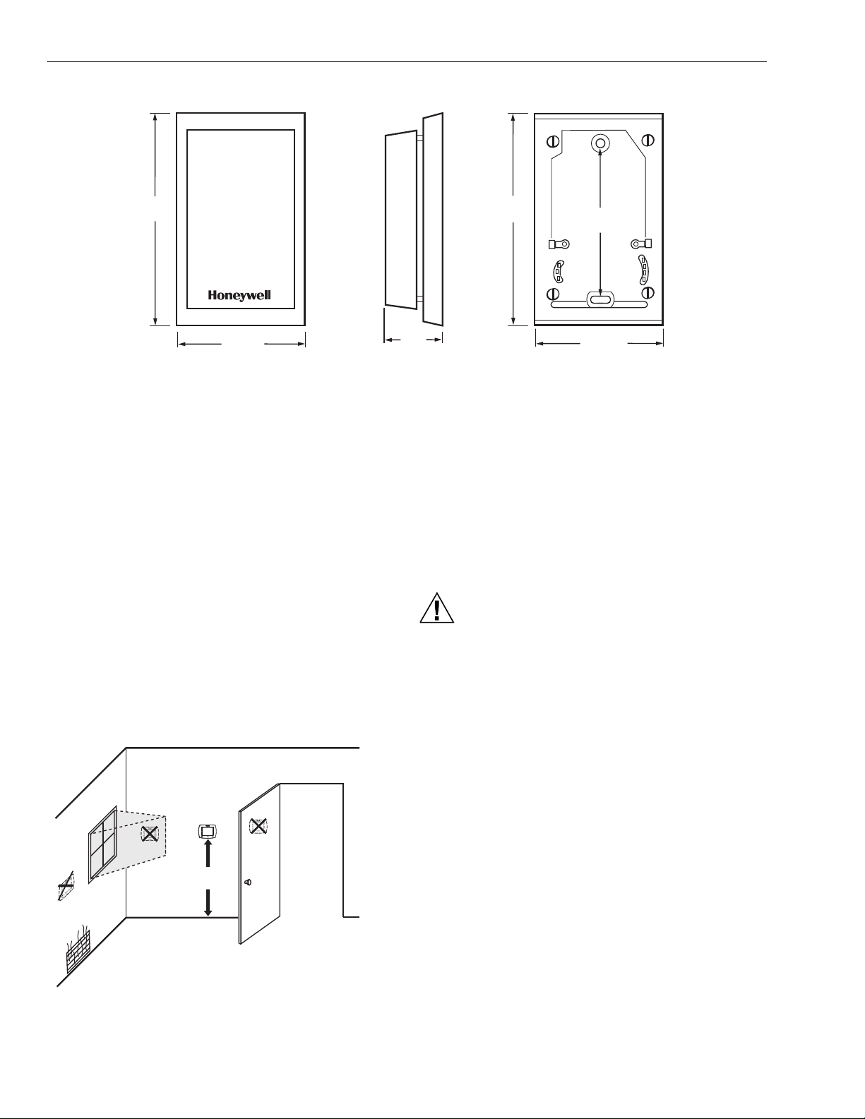
Fig. 4. C7189U Remote Indoor Sensor dimensions in in. (mm).
INSTALLATION
When Installing this Product...
1. Read these instructions carefully. Failure to follow the
instructions can damage the product or cause a hazardous condition.
2. Check the ratings given in the instructions to make sure
the product is suitable for your application.
3. Installer must be a trained, experienced service
technician.
4. After completing installation, use these instructions to
check out the product operation.
Selecting Location
Install the thermostat about 5 ft. (1.5m) above the floor in an
area with good air circulation at average temperature. See
Fig. 5.
4-5/8
1-1/8
(29)
(117)
3-1/4
(83)
2-3/4 (70)
Do not install the thermostat where it can be affected by:
— Drafts or dead spots behind doors and in corners.
— Hot or cold air from ducts.
— Radiant heat from sun or appliances.
— Concealed pipes and chimneys.
— Unheated (uncooled) areas such as an outside wall behind
the thermostat.
Installing Wallplate
Electrical Hazard.
Can cause electrical shock or equipment damage.
Disconnect power before wiring.
The thermostat can be mounted horizontally on the wall or on
a 4 in. x 2 in. (101.6 mm x 50.8 mm) wiring box.
68-0280—01 4
Fig. 5. Selecting thermostat location.
1. Position and level the wallplate (for appearance only).
2. Use a pencil to mark the mounting holes.
3. Remove the wallplate from the wall and, if drywall, drill
two 3/16-in. holes in the wall, as marked. For firmer
material such as plaster, drill two 7/32-in. holes. Gently
tap anchors (provided) into the drilled holes until flush
with the wall.

4. Position the wallplate over the holes, pulling wires
WALL
MOUNTING
HOLES
M19916
MOUNTING
SCREWS (2)
WALL ANCHORS (2)
WIRES THROUGH WALL
AND WIRE SLOT
CO
L
SC
S
H
UMP
S1
2
C
G
C
M19917
through the wiring opening. See Fig. 6.
5. Insert the mounting screws into the holes and tighten.
VisionPRO
TM
8000 Touchscreen Programmable Thermostat
Table 1. Selecting Terminal Identifications for
System Type.
Fig. 6. Mounting wallplate.
WIRING (FIG. 9 - 21)
All wiring must comply with local electrical codes and
ordinances.
1. Select set of terminal identifications (Table 1) that
corresponds with system type (conventional or heat
pump in Fig. 7).
2. Loosen the screws for the appropriate system type
selected; see Table 1. See Table 2 for terminal
designation descriptions. Insert wires in the terminal
block under the loosened screw. See Fig. 8.
3. Securely tighten each screw.
4. Push excess wire back into the hole.
5. Plug the hole with nonflammable insulation to prevent
drafts from affecting the thermostat.
6. See Fig. 9 through 21 for typical wiring hookups.
Wiring
Diagram
Reference
System Type
Wallplate
Ter min al
Identifications
Standard Heat/Cool Conventional 9, 10
Heat Only Conventional 11
Heat Only with Fan Conventional 12
Heat Only (Series 20)
Conventional 13
Power to open and
power to close zone
valves
Normally Open Zone
Conventional 14
Valves—Heat Only
Cool Only Conventional 15
Standard Multistage up
Conventional 16, 17
to 2 Heat/2 Cool
Heat Pump with No
Heat Pump 18, 19
Auxiliary Heat
Heat Pump with
Heat Pump 20, 21
Auxiliary Heat
EAT P
NVENTIONA
Y2
L
E
AUX
S1
S2
W2
S
REW TERMINAL
R
W
Y
RC
R
O/B
Y
G
C
M19951
Fig. 7. Selecting terminal identifications for
system type.
Fig. 8. Inserting wires in terminal block.
IMPORTANT
Use 18 gauge thermostat wire.
5 68-0280—01
VisionPRO
TM
8000 Touchscreen Programmable Thermostat
Table 2. Terminal Designation Descriptions.
Terminal
Designation Description
Rc (see Note 1)Power for cooling--connect to
secondary side of cooling system
transformer
R (see Note 1) Power for heating--connect to
secondary side of heating system
transformer
C (see Note 2) Common wire from secondary side of
cooling system transformer
W Heat relay
Y Compressor contactor
GFan relay
Y2 Second stage cooling
W2 Second stage heat relay
O/B (see Note 3)Changeover valve for heat pump
systems
AUX Auxiliary heat relay for heat pump
systems
E Emergency heat relay for heat pump
systems
L (see note 4) Equipment monitor for heat pump
systems
S1, S2 Optional outdoor or indoor remote
sensor
NOTES:
1. When used in a single-transformer system, leave
metal jumper wire in place between Rc and R. If
used on a two-transformer system, remove metal
jumper wire between Rc and R.
2. Common wire is optional when thermostat is used
with batteries.
3. If thermostat is configured for a heat pump system
in the Installer Setup, configure changeover valve
for cool (O-factory setting) or heat (B).
4. L terminal is an input (system monitor) when the
System mode is in the Heat, Off, Cool or Auto
position. L terminal is a 24 Vac output when
System mode is Emergency Heat. Must connect
the 24 Vac Common when using the L terminal.
See LED Indication section for more details.
CONVENTIONAL
Y2
W2
S1
S2
3
OUTDOOR/INDOOR
TEMPERATURE
SENSOR
POWER SUPPLY. PROVIDE DISCONNECT MEANS AND OVERLOAD
1
PROTECTION AS REQUIRED.
2
FACTORY INSTALLED JUMPER.
OPTIONAL OUTDOOR OR INDOOR REMOTE SENSOR. AVAILABLE
3
ON SELECT MODELS. WIRES MUST HAVE A CABLE SEPARATE
FROM THE THERMOSTAT CABLE.
RC
R
W
Y
G
C
2
FAN
RELAY
COMPRESSOR
CONTACTOR
HEAT RELAY
OPTIONAL
24 VAC
COMMON
CONNECTION
1
R
C
M19895
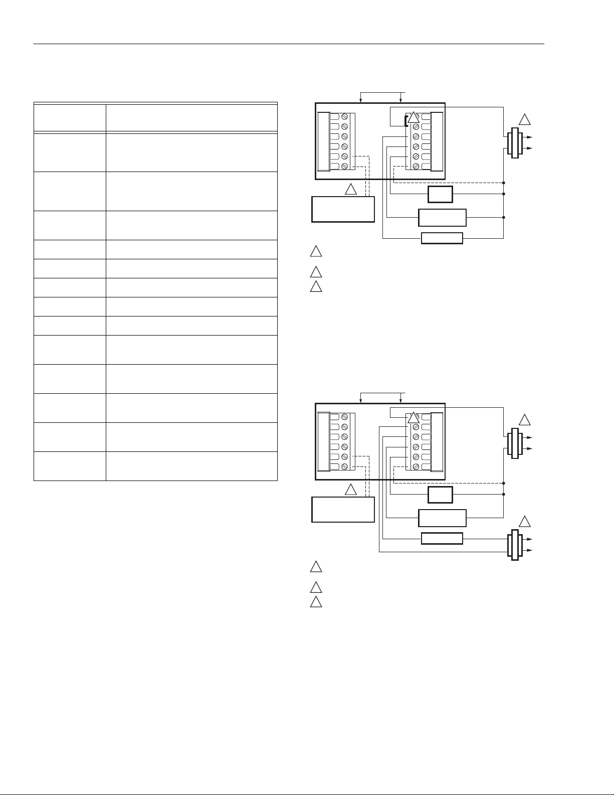
Fig. 9. Typical hookup of conventional single-stage heat
and cool system with single transformer
(1H/1C conventional).
CONVENTIONAL
Y2
W2
S1
S2
3
OUTDOOR/INDOOR
TEMPERATURE
SENSOR
1
POWER SUPPLY. PROVIDE DISCONNECT MEANS AND OVERLOAD
PROTECTION AS REQUIRED.
2
REMOVE FACTORY INSTALLED JUMPER.
3
OPTIONAL OUTDOOR OR INDOOR REMOTE SENSOR. AVAILABLE
ON SELECT MODELS. WIRES MUST HAVE A CABLE SEPARATE
FROM THE THERMOSTAT CABLE.
RC
R
W
Y
G
C
2
FAN
RELAY
COMPRESSOR
CONTACTOR
HEAT RELAY
OPTIONAL
24 VAC
COMMON
CONNECTION
1
R
C
1
C
R
M19896
Fig. 10. Typical hookup of conventional single-stage heat
and cool system with two transformers
(1H/1C conventional).
68-0280—01 6
VisionPRO
M19897
OUTDOOR/INDOOR
TEMPERATURE
SENSOR
HEAT RELAY
R
C
POWER SUPPLY. PROVIDE DISCONNECT MEANS AND OVERLOAD
PROTECTION AS REQUIRED.
FACTORY INSTALLED JUMPER.
OPTIONAL OUTDOOR OR INDOOR REMOTE SENSOR. AVAILABLE
ON SELECT MODELS. WIRES MUST HAVE A CABLE SEPARATE
FROM THE THERMOSTAT CABLE.
1
1
3
2
3
OPTIONAL
24 VAC
COMMON
CONNECTION
Y2
RC
S1
R
S2
W
W2
Y
G
C
2
CONVENTIONAL
M19898
OUTDOOR/INDOOR
TEMPERATURE
SENSOR
HEAT RELAY
FAN
RELAY
R
C
POWER SUPPLY. PROVIDE DISCONNECT MEANS AND OVERLOAD
PROTECTION AS REQUIRED.
FACTORY INSTALLED JUMPER.
OPTIONAL OUTDOOR OR INDOOR REMOTE SENSOR. AVAILABLE
ON SELECT MODELS. WIRES MUST HAVE A CABLE SEPARATE
FROM THE THERMOSTAT CABLE.
1
1
3
2
3
OPTIONAL
24 VAC
COMMON
CONNECTION
Y2
RC
S1
R
S2
W
W2
Y
G
C
2
CONVENTIONAL
TM
8000 Touchscreen Programmable Thermostat
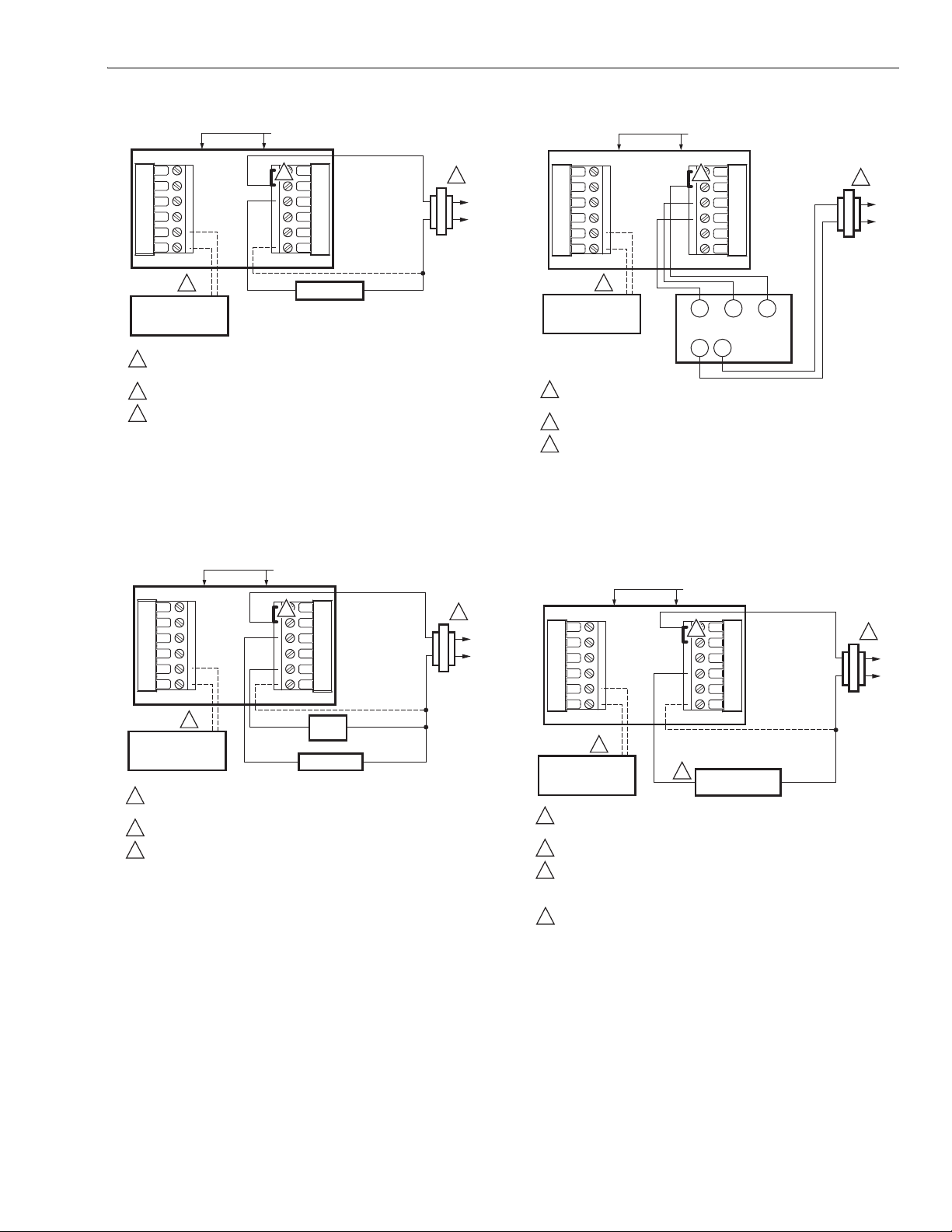
CONVENTIONAL
Fig. 11. Typical hookup of heat-only system
(1 H conventional).
Y2
W2
S1
S2
3
OUTDOOR/INDOOR
TEMPERATURE
SENSOR
1
POWER SUPPLY. PROVIDE DISCONNECT MEANS AND OVERLOAD
PROTECTION AS REQUIRED.
2
FACTORY INSTALLED JUMPER.
3
OPTIONAL OUTDOOR OR INDOOR REMOTE SENSOR. AVAILABLE
ON SELECT MODELS. WIRES MUST HAVE A CABLE SEPARATE
FROM THE THERMOSTAT CABLE.
RC
2
R
W
Y
G
C
W BR
TR
TR
SERIES 20
MOTOR OR
VALVE
1
R
C
M19899
Fig. 13. Typical hookup of heat only power to open and
power to close zone valve (Series 20) system.
CONVENTIONAL
Fig. 12. Typical hookup of heat only system with fan
(1H conventional).
Y2
W2
S1
S2
3
OUTDOOR/INDOOR
TEMPERATURE
SENSOR
1
POWER SUPPLY. PROVIDE DISCONNECT MEANS AND OVERLOAD
PROTECTION AS REQUIRED.
2
FACTORY INSTALLED JUMPER.
OPTIONAL OUTDOOR OR INDOOR REMOTE SENSOR. AVAILABLE
3
ON SELECT MODELS. WIRES MUST HAVE A CABLE SEPARATE
FROM THE THERMOSTAT CABLE.
CONFIGURE SYSTEM TYPE TO HEAT ONLY WITH NORMALLY OPEN
4
ZONE VALVES IN INSTALLER SETUP.
RC
2
R
W
Y
G
C
4
CONNECTION
NORMALLY OPEN
ALVE
ZONE V
OPTIONAL
24 VAC
COMMON
1
R
C
M22422
Fig. 14. Typical hookup of heat only system with normally
open zone valves.
7 68-0280—01
VisionPRO
M19900
OUTDOOR/INDOOR
TEMPERATURE
SENSOR
FAN
RELAY
R
C
POWER SUPPLY. PROVIDE DISCONNECT MEANS AND OVERLOAD
PROTECTION AS REQUIRED.
FACTORY INSTALLED JUMPER.
OPTIONAL OUTDOOR OR INDOOR REMOTE SENSOR. AVAILABLE
ON SELECT MODELS. WIRES MUST HAVE A CABLE SEPARATE
FROM THE THERMOSTAT CABLE.
1
1
3
2
3
OPTIONAL
24 VAC
COMMON
CONNECTION
Y2
RC
S1
R
S2
W
W2
Y
G
C
2
CONVENTIONAL
COMPRESSOR
CONTACTOR
M22438B
HEAT RELAY 2
COOL RELAY 2
OUTDOOR/INDOOR
TEMPERATURE
SENSOR
FAN
RELAY
R
C
POWER SUPPLY. PROVIDE DISCONNECT MEANS AND OVERLOAD
PROTECTION AS REQUIRED.
FACTORY INSTALLED JUMPER.
OPTIONAL OUTDOOR OR INDOOR REMOTE SENSOR. AVAILABLE
ON SELECT MODELS. WIRES MUST HAVE A CABLE SEPARATE
FROM THE THERMOSTAT CABLE.
1
1
3
2
3
OPTIONAL
24 VAC
COMMON
CONNECTION
MUST COME
FROM THE
COOLING
TRANSFORMER.
Y2
RC
S1
R
S2
W
W2
Y
G
C
2
CONVENTIONAL
COOL RELAY 1
HEAT RELAY 1
TM
8000 Touchscreen Programmable Thermostat
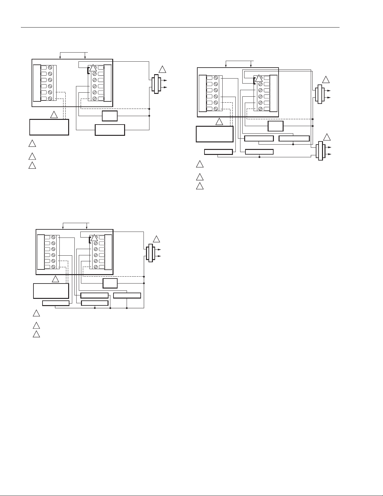
CONVENTIONAL
Fig. 15. Typical hookup of cool only system
(1C conventional).
Y2
W2
S1
S2
3
OUTDOOR/INDOOR
TEMPERATURE
SENSOR
HEAT RELAY 2
POWER SUPPLY. PROVIDE DISCONNECT MEANS AND OVERLOAD
1
PROTECTION AS REQUIRED.
2
FACTORY INSTALLED JUMPER.
OPTIONAL OUTDOOR OR INDOOR REMOTE SENSOR. AVAILABLE
3
ON SELECT MODELS. WIRES MUST HAVE A CABLE SEPARATE
FROM THE THERMOSTAT CABLE.
RC
2
R
W
Y
G
C
COOL RELAY 2
HEAT RELAY 1
CONNECTION
MUST COME
TRANSFORMER.
FAN
RELAY
COOL RELAY 1
OPTIONAL
24 VAC
COMMON
FROM THE
COOLING
1
M19902B
Fig. 17. Typical hookup of conventional multistage
two-stage heating and two-stage cooling in a
two-transformer system (2H/2C, 2H/1C or
1H/2C conventional).
R
C
1
R
C
Fig. 16. Typical hookup of conventional multistage
two-stage heating and two-stage cooling in a
68-0280—01 8
single-transformer system
(2H/2C, 2H/1C or 1H/2C conventional).
VisionPRO
C
G
C
P
ON
C
P
COMPRESSOR 1COMPRESSOR 2
M19904
CHANGEOVER
VALV E
FAN RELAY
R
C
1
1
2
3
4
5
5
OPTIONAL 24 VAC
ON
POWER SUPPLY. PROVIDE DISCONNECT MEANS AND OVERLOAD PROTECTION AS REQUIRED.
FACTORY INSTALLED JUMPER.
MUST CONNECT THE 24 VAC COMMON WHEN USING L. THE TERMINAL IS SHOWN AS EQUIPMENT MONITOR, CAN ALSO BE USED AS A 24 VAC
OUTPUT. SEE "HEAT PUMP LED" SECTION FOR MORE INFORMATION.
"O/B" TERMINAL SET TO CONTROL AS EITHER "O" OR "B" IN THE INSTALLER SETUP.
OPTIONAL OUTDOOR OR INDOOR REMOTE SENSOR. AVAILABLE ON SELECT MODELS. WIRES MUST HAVE A CABLE SEPARATE FROM THE
THERMOSTAT CABLE.
OUTDOOR/INDOOR
TEMPERATURE
SENSOR
TM
8000 Touchscreen Programmable Thermostat
EAT PUM
R
OPTIONAL 24 VAC
MMON CONNECTI
OUTDOOR/INDOOR
TEMPERATURE
4
SENSOR
POWER SUPPLY. PROVIDE DISCONNECT MEANS AND OVERLOAD PROTECTION AS REQUIRED.
1
FACTORY INSTALLED JUMPER.
2
"O/B" TERMINAL SET TO CONTROL AS EITHER "O" OR "B" IN THE INSTALLER SETUP.
3
OPTIONAL OUTDOOR OR INDOOR REMOTE SENSOR. AVAILABLE ON SELECT MODELS. WIRES MUST HAVE A CABLE SEPARATE
4
FROM THE THERMOSTAT CABLE.
CHANGEOVER
VALV E
FAN RELAY
COMPRESSOR
RELAY
M19903B
1
R
C
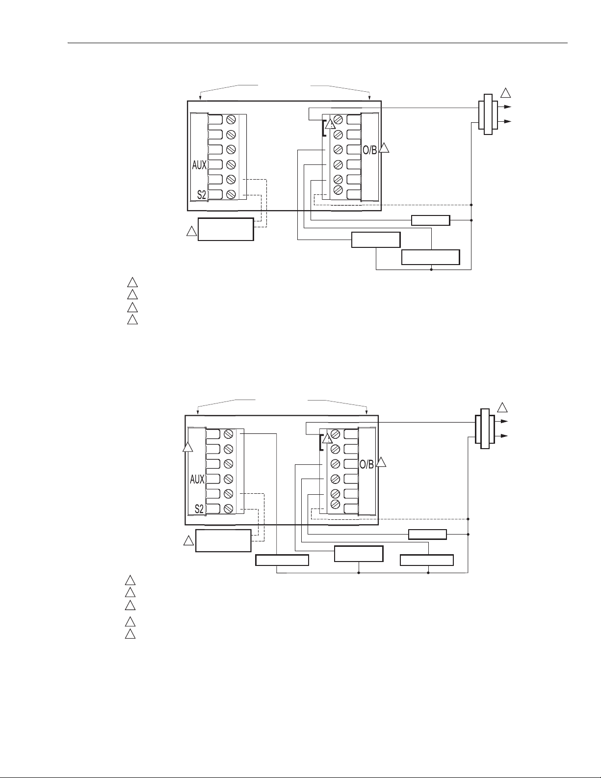
Fig. 18. Typical hookup of single-stage heat pump with no auxiliary/backup heat (1H/1C heat pump).
EAT PUM
Fig. 19. Typical hookup of multistage heat pump with no auxiliary/backup heat (2H/2C heat pump).
9 68-0280—01
R
MMON CONNECTI

VisionPRO
P
COMPRESSOR
RELAY
M19905
CHANGEOVER
VALV E
FAN RELAY
HEAT 2 RELAY
(AUXILIARY HEAT)
R
C
1
1
2
3
4
5
6
4
OPTIONAL 24 VAC
ON
EQUIPMENT
MONITOR
POWER SUPPLY. PROVIDE DISCONNECT MEANS AND OVERLOAD PROTECTION AS REQUIRED.
FACTORY INSTALLED JUMPER.
OUTDOOR SENSOR REQUIRED IN SYSTEM WITH FOSSIL FUEL BACKUP HEAT THAT IS NOT USING AN EXTERNAL FOSSIL FUEL KIT.
OPTIONAL OUTDOOR OR INDOOR REMOTE SENSOR. AVAILABLE ON SELECT MODELS. WIRES MUST HAVE A CABLE SEPARATE
FROM THE THERMOSTAT CABLE.
MUST CONNECT THE 24 VAC COMMON WHEN USING L. THE TERMINAL IS SHOWN AS EQUIPMENT MONITOR, CAN ALSO BE USED AS
A 24 VAC OUTPUT. SEE "HEAT PUMP LED" SECTION FOR MORE INFORMATION.
"O/B" TERMINAL SET TO CONTROL AS EITHER "O" OR "B" IN THE INSTALLER SETUP.
EMERGENCY
HEAT RELAY
3
OUTDOOR/INDOOR
TEMPERATURE
SENSOR
P
COMPRESSOR 2 COMPRESSOR 1
M19906
CHANGEOVER
VALV E
FAN RELAY
HEAT 2 RELAY
(AUXILIARY HEAT)
R
C
1
1
2
3
4
5
6
3
OPTIONAL 24 VAC
ON
EQUIPMENT
MONITOR
POWER SUPPLY. PROVIDE DISCONNECT MEANS AND OVERLOAD PROTECTION AS REQUIRED.
FACTORY INSTALLED JUMPER.
OUTDOOR SENSOR REQUIRED IN SYSTEM WITH FOSSIL FUEL BACKUP HEAT THAT IS NOT USING AN EXTERNAL FOSSIL FUEL KIT.
OPTIONAL OUTDOOR OR INDOOR REMOTE SENSOR. AVAILABLE ON SELECT MODELS. WIRES MUST HAVE A CABLE SEPARATE
FROM THE THERMOSTAT CABLE.
MUST CONNECT THE 24 VAC COMMON WHEN USING L. THE TERMINAL IS SHOWN AS EQUIPMENT MONITOR, CAN ALSO BE USED AS
A 24 VAC OUTPUT. SEE "HEAT PUMP LED" SECTION FOR MORE INFORMATION.
"O/B" TERMINAL SET TO CONTROL AS EITHER "O" OR "B" IN THE INSTALLER SETUP.
EMERGENCY
HEAT RELAY
4
OUTDOOR/INDOOR
TEMPERATURE
SENSOR
TM
8000 Touchscreen Programmable Thermostat
EAT PUM
MMON CONNECTI
Fig. 20. Typical hookup of single-stage heat pump with auxiliary/backup heat (2H/1C heat pump).
EAT PUM
68-0280—01 10
Fig. 21. Typical hookup of multistage heat pump with auxiliary/backup heat (3H/2C heat pump).
MMON CONNECTI
POWER THE THERMOSTAT
M22213
PINS ON
BACK OF
THERMOSTAT
WALLPLATE
TERMINAL
SCREW
BLOCK
VisionPRO
TM
8000 Touchscreen Programmable Thermostat
You can choose from three methods to power the thermostat:
• Batteries only (AAA alkaline).
• 24 Vac common wire only.
• 24 Vac common wire with battery backup (AAA alkaline).
Wiring 24 Vac Common
• Single-Transformer System—Connect the common side of
the transformer to the C screw terminal of the thermostat
wallplate. Leave the metal jumper wire in place between
Rc and R.
• Two-Transformer System—Connect the common side of
the cooling transformer to the C screw terminal of the
thermostat wallplate. Remove the metal jumper wire
between Rc and R.
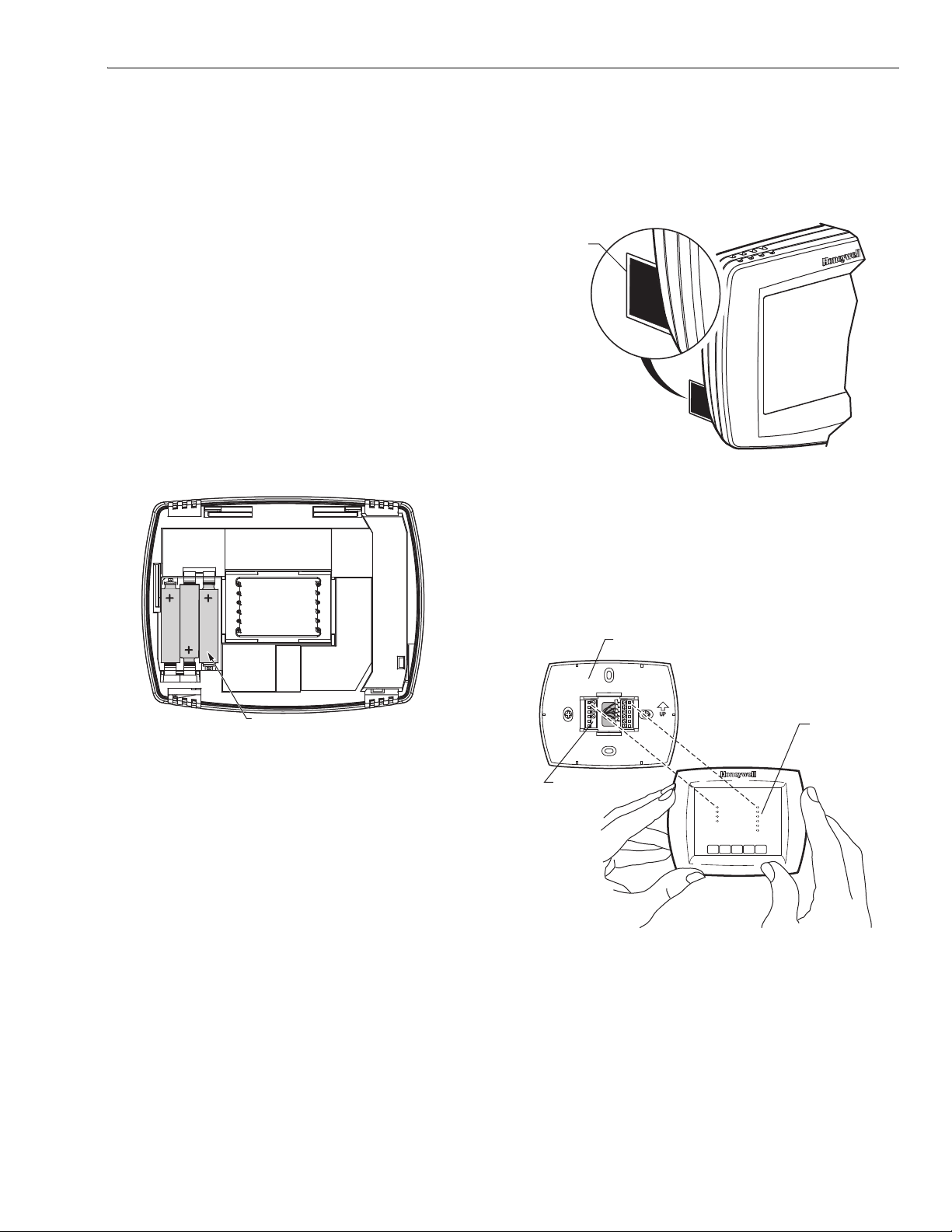
Installing Batteries
1. Install three AAA alkaline batteries on the back of the
thermostat as marked on the thermostat. See
Fig. 22.
2. Locate and remove the tab labeled, Remove, in the
lower left corner on the thermostat back. See
Fig. 23.
REMOVE
TAB
INSTALLATION
REMOVE DURING
INSTALLATION
REMOVE DURING
Fig. 23. Remove tab labeled, Remove, on
thermostat back.
Mount Thermostat to Wallplate
1. Align the terminal screw blocks with the pins on the
back of the thermostat. Push the thermostat straight
onto the wallplate until it snaps into place. See Fig 24.
M19920
BATTERIES (3)
Fig. 22. Installing batteries.
M19918
Fig. 24. Mount thermostat to wallplate.
11 68-0280—01
VisionPRO
CAUTION
CAUTION
M7514
TM
8000 Touchscreen Programmable Thermostat
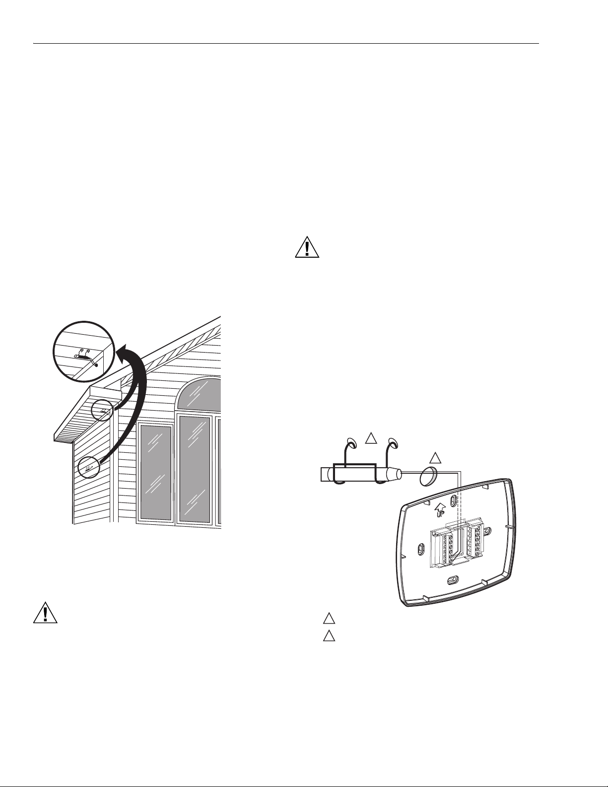
Locate and Mount C7089U Outdoor Temperature Sensor (Optional)
Mount the sensor where (see Fig. 25):
• cannot tamper with settings.
• there is good air circulation.
• it can measure true outdoor ambient temperature.
• surface is flat.
• wire distance between C7089 and thermostat is less than
200 feet.
Do not mount the sensor:
• in direct sunlight.
• where hot or cold air blows on the sensor. Discharge line
from an outdoor compressor unit, vent or fan causes
inaccurate temperature readings.
• where snow, ice or debris can cover it.
Use the following steps to mount the sensor:
1. Remove the sensor from the mounting clip.
2. Mark the area on the location selected for mounting the
sensor mounting clip.
3. Mount the clip.
IMPORTANT
Erratic temperature readings from a sensor can
occur as a result of any of the wiring practices
described below. Avoid these practices to assure
correct operation. Use shielded cable to reduce
interference if rerouting sensor wiring is not possible.
— Be sure wires have a cable separate from the
thermostat cable.
— Do not route temperature sensor wiring with building
power wiring, next to control contactors or near light
dimming circuits, electric motors or welding
equipment.
— Avoid poor wiring connections.
— Avoid intermittent or missing building earth ground.
Electrical Shock Hazard.
Can cause electrical shock or equipment damage.
Disconnect power supply before connecting wiring.
Wiring must comply with applicable codes, ordinances and
regulations:
1. Wire C7089 Outdoor Sensor to S1and S2 terminals on
the thermostat. If leadwire provided is not long enough
(60 in.), run a cable to a hole at C7089 location.
a. Using color-coded, 18-gauge thermostat wire is
recommended. For example of general wiring of
C7089, see Fig. 26.
b. Pigtail wiring can be used.
2. Mount C7089 in its mounting clip.
3. Plug wiring hole using nonhardening caulk or putty.
Fig. 25. Typical locations for C7089U Outdoor Sensor.
Wire C7089U Outdoor Sensor
Electrical Interference (Noise) Hazard.
Can cause erratic system operation.
Keep wiring at least one foot away from large inductive
loads such as motors, line starters, lighting ballasts
and large power distribution panels.
Use shielded cable to reduce interference when
rerouting is not possible.
1
C7089
1
USE APPROPRIATE MOUNTING MEANS FOR THE
TYPE OF STRUCTURE.
2
PLUG WIRING HOLE WITH NON-HARDENING CAULK
OR PUTTY.
WIRING HOLE
THROUGH
2
STRUCTURE
M19970
Fig. 26. Wire C7089 Outdoor Sensor to the thermostat.
68-0280—01 12
 Loading...