


Owner`s Manual
BF4A
Includes US and Canadian Models
© 2023 Honda Motor Co., Ltd. - All Rights Reserved
•
BF5D • BF6A

The engine exhaust from this product
contains chemicals known to the State of
California to cause cancer, birth defects
or other reproductive harm.
Keep this Owner’s Manual handy, so you can refer to it at any time. This Owner’s
Manual is considered a permanent part of the outboard motor and should remain with
the outboard motor if resold.
The information and specifications included in this publication were in effect at the
time of approval for printing. Honda Motor Co., Ltd. reserves the right, however, to
discontinue or change specifications or design at any time without notice and without
incurring any obligation whatsoever. No part of this publication may be reproduced
without written permission.

INTRODUCTION
Congratulations on your selection of
a Honda outboard motor. We are
certain you will be pleased with your
purchase of one of the finest outboard
motors on the market.
We want to help you get the best
results from your new outboard motor
and to operate it safely. This manual
contains information on how to do
that; please read it carefully.
As you read this manual you will find
information preceded by a
symbol. That information
is intended to help you avoid damage
to your outboard motor, other
property, or the environment.
We suggest you read the warranty
policy to fully understand its
coverage and your responsibilities of
ownership (see page 112).
When your outboard motor needs
scheduled maintenance, keep in mind
that your Honda Marine dealer is
specially trained in servicing Honda
outboard motors. Your Honda Marine
dealer is dedicated to your
satisfaction and will be pleased to
answer your questions and concerns.
1

INTRODUCTION
A FEW WORDS ABOUT
SAFETY
Your safety and the safety of others
are very important. And using this
outboard motor safely is an important
responsibility.
To help you make informed decisions
about safety, we have provided
operating procedures and other
information on labels and in this
manual. This information alerts you
to potential hazards that could hurt
you or others.
Of course, it is not practical or
possible to warn you about all the
hazards associated with operating or
maintaining an outboard motor. You
must use your own good judgment.
You will find important safety information in a variety of forms, including:
• Safety Labels – on the outboard motor.
• Safety Messages – preceded by a safety alert symbol and one of three
signal words, DANGER, WARNING, or CAUTION.
These signal words mean:
You WILL be KILLED or SERIOUSLY
HURT if you don’t follow instructions.
You CAN be KILLED or SERIOUSLY
HURT if you don’t follow instructions.
You CAN be HURT if you don’t follow
instructions.
• Safety Headings – such as IMPORTANT SAFETY INFORMATION.
• Safety Section – such as OUTBOARD MOTOR SAFETY.
• Instructions – how to use this outboard motor correctly and safely.
This entire book is filled with important safety information – please read it
carefully.
2

CONTENTS
OUTBOARD MOTOR SAFETY ................................... 6
IMPORTANT SAFETY INFORMATION .............. 6
SAFETY LABEL LOCATIONS .............................. 8
CONTROLS AND FEATURES ................................... 14
CONTROL AND FEATURE
IDENTIFICATION CODES ............................... 14
COMPONENT AND CONTROL LOCATIONS ... 15
CONTROLS ............................................................ 17
Emergency Stop Switch Clip and Emergency
Stop Switch ..................................................... 17
Choke Knob ........................................................ 17
Throttle Grip ........................................................ 18
Throttle Friction Knob ........................................ 18
Gearshift Lever .................................................... 19
Fuel Valve Lever ................................................. 19
Fuel Filler Cap Vent Knob .................................. 21
Starter Grip .......................................................... 22
Engine Cover Latch .............................................22
Transom Angle Adjusting Rod ........................... 22
Steering Friction Bolt .......................................... 23
Tilt Lever ............................................................. 23
Handle Stopper .................................................... 23
INDICATORS .........................................................24
Oil Pressure Indicator ..........................................24
Cooling System Indicator .................................... 25
OTHER FEATURES ...............................................25
Rev Limiter ..........................................................25
Anode ................................................................... 25
Fuel Hose Connector Cap and Fuel Hose
Connector ........................................................26
Portable Fuel Tank ...............................................26
Fuel Filler Cap Vent Knob ..................................26
Fuel Priming Bulb ...............................................27
Battery Charge Cable ...........................................27
INSTALLATION ..........................................................30
POWER REQUIREMENTS ...................................30
INSTALLATION POSITION .................................30
ATTACHMENT ......................................................31
TRANSOM ANGLE ADJUSTMENT ....................31
BATTERY CONNECTIONS ..................................32
Battery .................................................................32
Battery Terminals ................................................33
BEFORE OPERATION .................................................34
ARE YOU READY TO GET UNDERWAY? ........ 34
IS YOUR OUTBOARD MOTOR
READY TO GO? .................................................34
3

CONTENTS
OPERATION ................................................................ 36
SAFE OPERATING PRECAUTIONS ................... 36
BREAK-IN PROCEDURE ..................................... 36
TRANSOM ANGLE ADJUSTMENT .................... 37
PRIMING THE CARBURETOR WITH
GASOLINE ......................................................... 37
PORTABLE FUEL TANK ..................................... 39
FUEL HOSE CONNECTIONS .............................. 40
FUEL PRIMING ..................................................... 40
INFREQUENT OR OCCASIONAL USE .............. 41
STARTING THE ENGINE .................................... 41
EMERGENCY STARTING ................................... 45
STOPPING THE ENGINE ..................................... 51
Emergency Engine Stopping ............................... 51
Normal Engine Stopping ..................................... 51
GEARSHIFTING AND THROTTLE
OPERATION ......................................................53
STEERING .............................................................. 54
CRUISING .............................................................. 55
SHALLOW WATER OPERATION ...................... 56
MOORING, BEACHING, LAUNCHING ............. 57
SERVICING YOUR OUTBOARD MOTOR ............... 58
THE IMPORTANCE OF MAINTENANCE .......... 58
MAINTENANCE SAFETY ................................... 59
TOOL KIT AND EMERGENCY STARTER
ROPE ...................................................................60
MAINTENANCE SCHEDULE ..............................61
ENGINE COVER REMOVAL AND
INSTALLATION ................................................63
Engine Oil Level Check ...................................... 64
Engine Oil Change ...............................................65
Engine Oil Recommendations .............................67
Gear Case Oil Change .........................................67
Lubrication Points ................................................69
Spark Plug Service ...............................................70
REFUELING ...........................................................71
FUEL RECOMMENDATIONS .............................. 74
Fuel Filter Inspection and Replacement ..............75
Portable Fuel Tank and Tank Filter Cleaning .....77
Recoil Starter Rope Inspection ............................78
Anode Replacement .............................................78
Propeller and Shear Pin Replacement .................79
4

CONTENTS
CLEANING AND FLUSHING .................................... 81
Cleaning and Flushing ......................................... 81
STORAGE ..................................................................... 84
Fuel ...................................................................... 84
Engine Oil ........................................................... 86
Engine Cylinder .................................................. 86
STORAGE PRECAUTIONS .................................. 87
REMOVAL FROM STORAGE ............................. 88
TRANSPORTING ......................................................... 89
WITH OUTBOARD MOTOR INSTALLED ON
BOAT .................................................................. 89
WITH OUTBOARD MOTOR REMOVED FROM
BOAT .................................................................. 90
TAKING CARE OF UNEXPECTED PROBLEMS ..... 91
ENGINE WILL NOT START ................................ 91
HARD STARTING OR STALLS AFTER
STARTING ......................................................... 93
ENGINE OVERHEATS ......................................... 94
ENGINE WILL NOT DRIVE THE
PROPELLER
BATTERY WILL NOT CHARGE
(Equipped type) ................................................... 96
Fuse Replacement ...............................................96
....................................................... 95
OIL PRESSURE INDICATOR GOES OFF AND
ENGINE SPEED IS LIMITED ........................... 97
SUBMERGED OUTBOARD MOTOR .................. 98
TECHNICAL INFORMATION ..................................100
Serial Number Locations .......................................100
Carburetor Modification for High Altitude
Operation ........................................................... 101
Battery .................................................................... 101
Emission Control System Information ..................102
Star Label ...............................................................104
Specifications .........................................................106
Specifications .........................................................107
Specifications .........................................................108
CONSUMER INFORMATION ..................................109
Dealer Locator Information ...............................109
Honda Publications ............................................109
Customer Service Information ...........................110
Warranty Statements ..............................................112
Distributor’s Limited Warranty ............................. 112
Emission Control System Warranty ...................... 117
Distributor’s Warranty ...........................................122
INDEX .........................................................................125
5

OUTBOARD MOTOR SAFETY
IMPORTANT SAFETY INFORMATION
The Honda BF4A, BF5D and BF6A
outboard motors are designed for use
with boats that have a suitable
manufacturer’s power
recommendation. Other uses can
result in injury to the operator or
damage to the outboard motor and
other property.
Most injuries or property damage can
be prevented if you follow all
instructions in this manual and on the
outboard motor. The most common
hazards are discussed in this chapter,
along with the best way to protect
yourself and others.
Operator Responsibility
• It is the operator’s responsibility to
provide the necessary safeguards to
protect people and property.
Know how to stop the engine
quickly in case of emergency.
Understand the use of all controls.
• Stop the engine immediately if
anyone falls overboard, and do not
run the engine while the boat is
near anyone in the water.
• Always stop the engine if you must
leave the controls for any reason.
• Attach the emergency stop switch
lanyard securely to the operator.
• Always wear a PFD (Personal
Flotation Device) while on the
boat.
• Familiarize yourself with all laws
and regulations relating to boating
and the use of outboard motors.
• Be sure that anyone who operates
the outboard motor receives proper
instruction.
• Be sure the outboard motor is
properly mounted on the boat.
• Do not remove the engine cover
while the engine is running.
6

OUTBOARD MOTOR SAFETY
Refuel With Care
• Gasoline is extremely flammable,
and gasoline vapor can explode.
Refuel outdoors, in a
well-ventilated area, with the
engine stopped. Never smoke near
gasoline, and keep other flames and
sparks away.
• Remove any portable fuel tank
from the boat for refueling. Keep
the portable fuel tank away from
the battery or other potential spark
sources.
• Refuel carefully to avoid spilling
fuel. Avoid overfilling the fuel
tank.
• After refueling, tighten the filler
cap securely. If any fuel is spilled,
make sure the area is dry before
starting the engine.
Carbon Monoxide Hazard
Exhaust contains poisonous carbon
monoxide, a colorless, odorless gas.
Breathing carbon monoxide can
cause loss of consciousness and may
lead to death.
If you run the engine in an area that is
confined, or even partly enclosed, the
air you breathe could contain a
dangerous amount of exhaust gas.
Never run your outboard inside a
garage or other enclosure.
Running the engine of your
outboard while in an enclosed or
partially enclosed area can cause
a rapid build-up of toxic carbon
monoxide gas.
Breathing this colorless, odorless
gas can quickly cause
unconsciousness and lead to
death.
Only run your outboard engine
when it is located in a well
ventilated area outdoors.
7

OUTBOARD MOTOR SAFETY
SAFETY LABEL LOCATIONS
US, Puerto Rico, and US Virgin Islands Types
8

OUTBOARD MOTOR SAFETY
FUEL CAUTION
PORTABLE FUEL TANK
FUEL CAUTION
CAUTION
KEEP TOTALLY CLOSED WHEN
NOT IN USE. KEEP AWAY FROM
HEAT, SPARKS, AND OPEN FLAME.
SECURE ABOVE DECK IN WELL
VENTILATED AREA. DO NOT USE
FOR LONG TERM FUEL STORAGE.
DO NOT USE FUEL/OIL MIXTURE.
GASOLINE FLAMMABLE DANGER
DANGER
HARMFUL OR FATAL IF SWALLOWED.
KEEP OUT OF REACH OF CHILDREN.
IF SWALLOWED, DO NOT INDUCE
VOMITING. CALL A PHYSICIAN
IMMEDIATELY.
GASOLINE FLAMMABLE DANGER
The labels shown here contain important safety information. Please read them carefully. These labels are considered
permanent parts of your outboard motor. If a label comes off or becomes hard to read, contact an authorized Marine
dealer for a replacement.
9

OUTBOARD MOTOR SAFETY
Canadian Types
10

OUTBOARD MOTOR SAFETY
FUEL CAUTION
PORTABLE FUEL TANK
GASOLINE FLAMMABLE DANGER
GAZOLINE INFLAMMABLE DANGEREUX
DANGER
HARMFUL OR FATAL IF SWALLOWED.
KEEP OUT OF REACH OF CHILDREN.
IF SWALLOWED, DO NOT INDUCE
VOMITING. CALL A PHYSICIAN
IMMEDIATELY.
CAUTION
KEEP TOTALLY CLOSED WHEN
NOT IN USE. KEEP AWAY FROM
HEAT, SPARKS, AND OPEN FLAME.
SECURE ABOVE DECK IN WELL
VENTILATED AREA. DO NOT USE
FOR LONG TERM FUEL STORAGE.
DO NOT USE FUEL/OIL MIXTURE.
GASOLINE FLAMMABLE DANGER
GAZOLINE INFLAMMABLE DANGEREUX
GASOLINA PELIGRO FLAMABLE
FUEL CAUTION
The labels shown here contain important safety information. Please read them carefully. These labels are considered
permanent parts of your outboard motor. If a label comes off or becomes hard to read, contact an authorized Marine
dealer for a replacement.
11

OUTBOARD MOTOR SAFETY
• Gasoline is harmful or fatal if
swallowed. Keep the fuel tank
out of reach of children.
• Gasoline is extremely
flammable and is explosive
under certain conditions.
Refuel in a well-ventilated area
with the engine stopped.
• Do not smoke or allow flames
or sparks where the engine is
refueled or where gasoline is
stored.
• Do not overfill the fuel tank.
After refueling make sure that
the fuel filler cap is closed
properly and securely.
• Be careful not to spill any fuel
while refueling. Spilled fuel or
fuel vapor may ignite. If any
fuel is spilled, make sure that
the area is dry before starting
the engine.
US, Puerto Rico, and US Virgin
Islands Types
12

Canadian Types
• Honda outboard motor is
designed to give safe and
dependable service if operated
according to instructions.
Read and understand the
Owner’s Manual before
operating the outboard motor.
Failure to do so could result in
personal injury or equipment
damage.
• Gasoline is harmful or fatal if
swallowed. Keep the fuel tank
out of reach of children.
• Gasoline is extremely
flammable and is explosive
under certain conditions.
Refuel in a well-ventilated
area with the engine stopped.
• Do not smoke or allow flames
or sparks where the engine is
refueled or where gasoline is
stored.
• Do not overfill the fuel tank.
After refueling make sure that
the fuel filler cap is closed
properly and securely.
• Be careful not to spill any fuel
while refueling. Spilled fuel or
fuel vapor may ignite. If any
fuel is spilled, make sure that
the area is dry before starting
the engine.
OUTBOARD MOTOR SAFETY
13

CONTROLS AND FEATURES
(Example)
S
Destination
H
Charging System
N=Without System
(Optional Equipment)
N□
Throttle Type
H=Tiller Handle Type
Shaft Length
S=Short Shaft
L=Long Shaft
CONTROL AND FEATURE IDENTIFICATION CODES
Model BF4A BF5D BF6A
Type SHN□ LHN□ SHN□ SH□ LHN□ LH□ SHN□ SH□ LHN□ LH□
Shaft Length
Fuel Tank (Internal fuel tank)
Charging System
Refer to this chart for an explanation of the Type Codes used in this manual to identify control and feature applications.
For the detailed equipment conditions of optional components, consult your Honda dealer.
S●●● ●●
L●●●●●
●●●●●●●●●●
●●●●
BF4A/BF5D/BF6A are provided with the
following types according to the shaft length
and charging system.
14
•Shaft Length
S: Short Shaft
L: Long Shaft
• Control System
H: Tiller Handle Type
•Charging System
N: Without System
(Optional Equipment)

COMPONENT AND CONTROL LOCATIONS
GEARSHIFT LEVER
FUEL FILLER CAP
FUEL FILLER CAP VENT KNOB
TILLER HANDLE
FUEL VALVE
LEVER
CLAMP SCREW
WATER INTAKE PORT (each side)
PROPELLER
ANTIVENTILATION
PLATE
TRANSOM ANGLE
ADJUSTING ROD
COOLING SYSTEM
INDICATOR
ENGINE COVER
OIL FILLER CAP/DIPSTICK
SPARK PLUG
STARTER GRIP
THROTTLE
GRIP
THROTTLE
FRICTION KNOB
HANDLE STOPPER
STEERING FRICTION
BOLT
STERN BRACKET
GEAR OIL LEVEL SCREW
GEAR OIL DRAIN/FILL SCREW
EXHAUST PORT
ANODE
WA SH S CR E W
(FLUSH SCREW)
ENGINE OIL
DRAIN BOLT
ENGINE
COVER LATCH
TILT LEVER
CONTROLS AND FEATURES
15
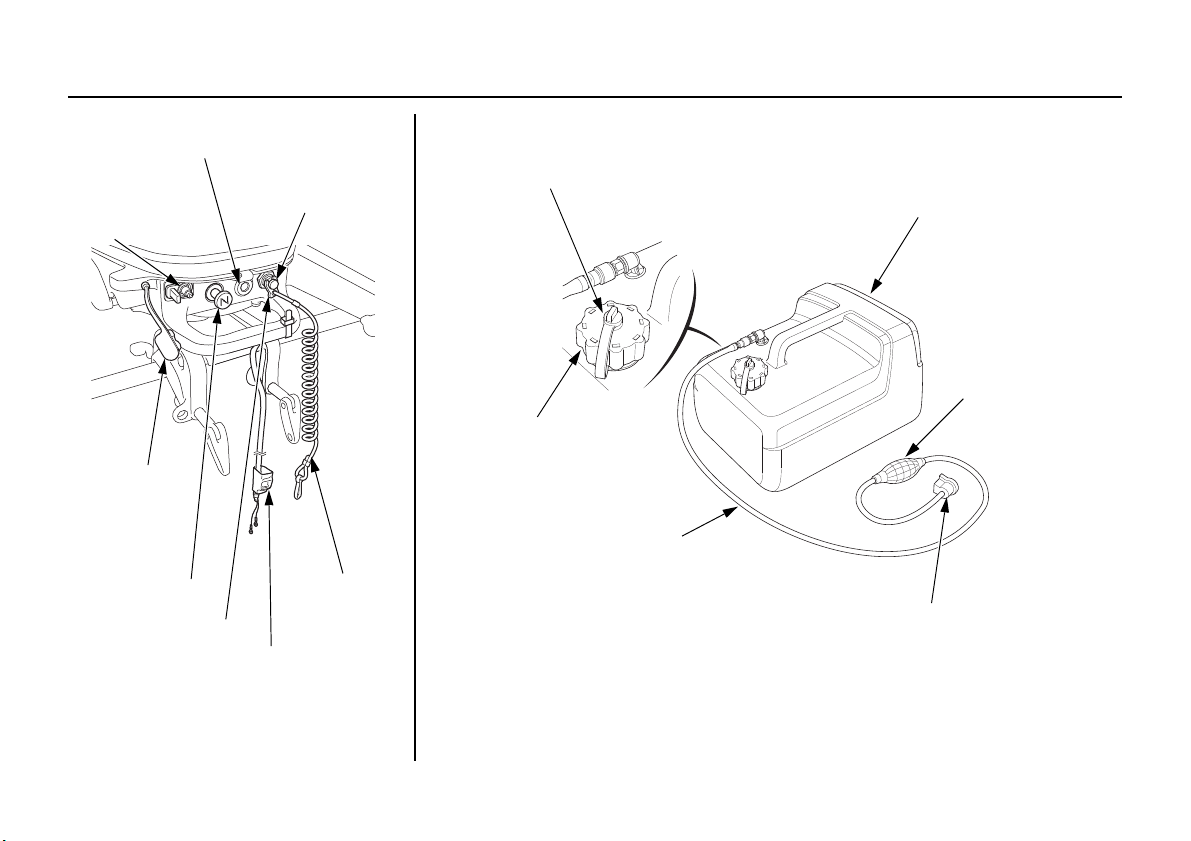
CONTROLS AND FEATURES
OIL PRESSURE
INDICATOR
FUEL HOSE
CONNECTOR
(MALE)
(BF5D and
BF6A only)
EMERGENCY STOP
SWITCH
FUEL HOSE
CONNECTOR
CAP
(BF5D and
BF6A only)
CHOKE KNOB
EMERGENCY STOP
SWITCH CLIP
EMERGENCY
STOP SWITCH
LANYARD
BATTERY
CHARGE CABLE
(equipped type)
VENT KNOB
FUEL FILLER CAP
PORTABLE FUEL TANK
FUEL PRIMING
BULB
FUEL HOSE
FUEL HOSE CONNECTOR
(FEMALE)
Portable Fuel Tank (standard or optionally applicable equipment)
16

CONTROLS AND FEATURES
EMERGENCY STOP
SWITCH LANYARD
EMERGENCY STOP
SWITCH CLIP
EMERGENCY
STOP SWITCH
PUSH
EMERGENCY STOP
SWITCH CLIP
EMERGENCY STOP
SWITCH LANYARD
CHOKE KNOB
OFF
ON
CONTROLS
Emergency Stop Switch Clip and Emergency Stop Switch
The emergency stop switch clip must
be inserted in the emergency stop
switch in order for the engine to start
and run. The emergency stop switch
lanyard must be attached securely to
the operator or to the PFD (Personal
Flotation Device) equipped to an
operator.
When used as described, the
emergency stop switch and
emergency stop switch lanyard
system stops the engine if the
operator falls away from the controls.
A spare emergency stop switch clip is
supplied with the tool kit.
Choke Knob
The choke knob opens and closes the
choke valve in the carburetor.
The ON position enriches the fuel
mixture for starting a cold engine.
The OFF position provides the correct
fuel mixture for operation after starting,
and for restarting a warm engine.
The choke knob is also used to restart
the engine after supplying fuel when
the internal fuel tank is out of fuel. For
more information, refer to page 44.
17

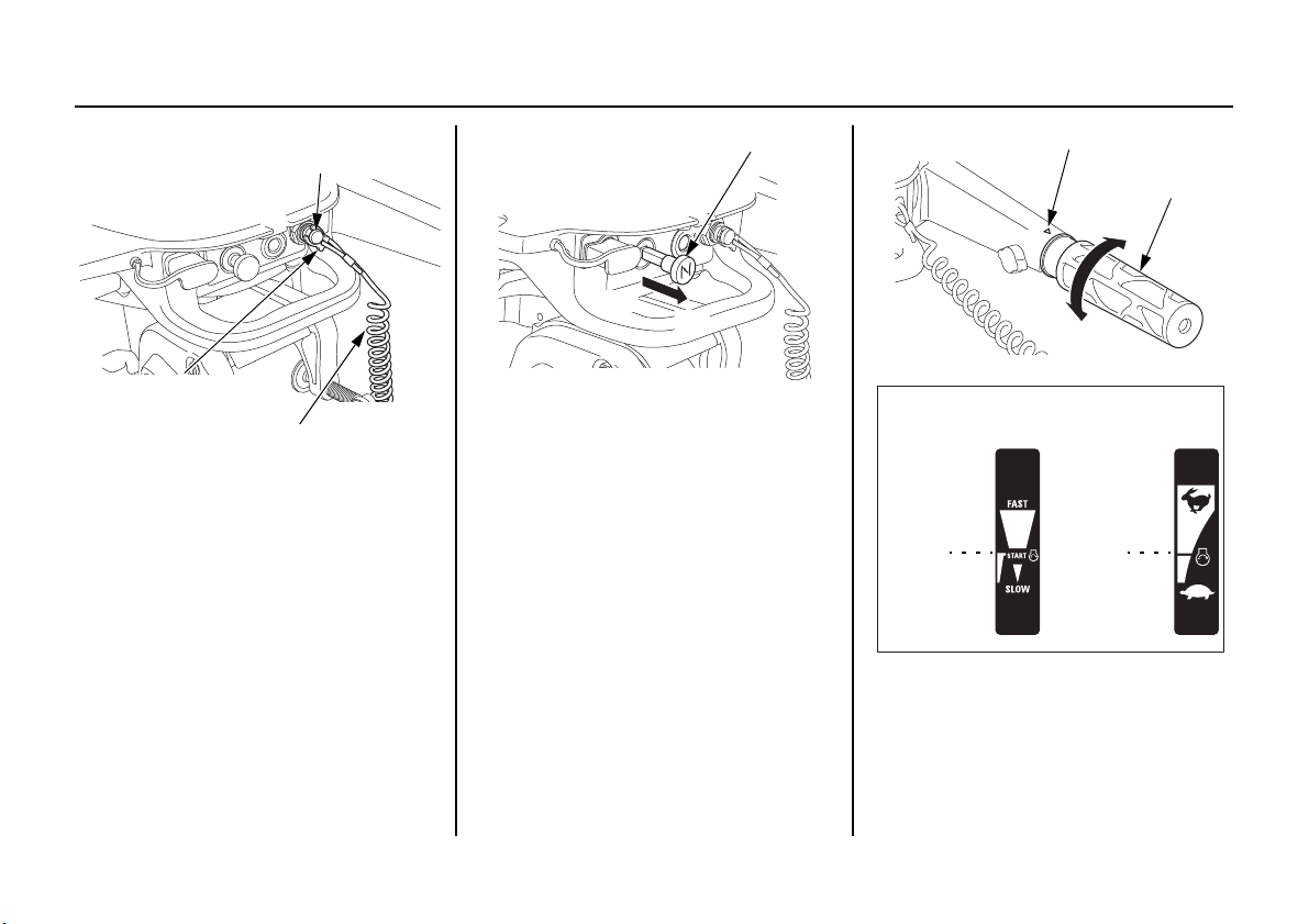
CONTROLS AND FEATURES
INDEX MARK
THROTTLE GRIP
SLOW
FAST
[USA model]
[Canadian model]
FAS T
FAST
SLOW
SLOW
THROTTLE FRICTION KNOB
TO INCREASE
FRICTION
TO DECREASE
FRICTION
Throttle Grip
The throttle grip controls engine
speed.
An index mark on the tiller handle
shows throttle position and is helpful
for setting the throttle correctly when
starting (p. 44).
Throttle Friction Knob
The throttle friction knob adjusts
resistance to throttle grip rotation.
Turn the knob clockwise to increase
friction for holding a throttle setting
while cruising.
Turn the knob counterclockwise to
decrease friction for easy throttle grip
rotation.
18

CONTROLS AND FEATURES
GEARSHIFT LEVER
N (neutral)
R (reverse)
F (forward)
[USA model]
[Canadian model]
N (neutral)
R (reverse)
F (forward)
N (neutral)
R (reverse)
F (forward)
FUEL VALVE LEVER
ON (BF4A)
or
INTERNAL
FUEL TANK
POSITION
(BF5D and
BF6A)
OFF (BF4A) or
PORTABLE FUEL
TANK POSITION
(BF5D and BF6A)
Gearshift Lever
Fuel Valve Lever
The gearshift lever is used to select F
(forward), N (neutral), or R (reverse)
gears.
If the gearshift lever is in the F
(forward) or R (reverse) position, the
recoil starter will not operate.
19

CONTROLS AND FEATURES
[BF4A]
[BF5D and BF6A]
ON
OFF
INTERNAL
FUEL TANK
POSITION
PORTABLE
FUEL TANK
POSITION
(BF4A)
The fuel valve opens and closes the
passage between the internal fuel tank
and the carburetor.
The fuel valve lever must be in the
ON position for the engine to run.
When the engine is not in use, leave
the fuel valve lever in the OFF
position to prevent carburetor
flooding and to reduce the possibility
of fuel leakage.
(BF5D and BF6A)
The fuel valve lever has internal fuel
tank position and portable fuel tank
position.
When using the internal fuel tank,
turn the fuel valve lever to the
internal fuel tank position.
When not connecting the portable
fuel tank, fuel is shut off at the
portable fuel tank position.
When using the portable fuel tank,
turn the fuel valve lever all the way to
the portable fuel tank position.
20

CONTROLS AND FEATURES
CLOSE
VENT KNOB
OPEN
FUEL FILLER CAP
(BF4A)
(BF5D and BF6A)
LEVER POSITION FUNCTION
ON Fuel from the internal fuel tank is supplied.
OFF Fuel supply is shut off.
Set the fuel valve lever to the “OFF”
position during transporting or storing the
outboard motor.
LEVER POSITION FUNCTION
INTERNAL FUEL
TANK
PORTABLE FUEL
TANK
Fuel from the internal fuel tank is supplied.
• Fuel from the portable fuel tank is
supplied.
• If the portable fuel tank is not
connected, fuel supply is shut off.
Set the fuel valve lever to the
“PORTABLE FUEL TANK” position
during transporting or storing the
outboard motor.
Fuel Filler Cap Vent Knob
(Internal Fuel Tank)
The fuel filler cap is provided with a
vent knob to seal the fuel tank. Open
the vent by turning the vent knob
counterclockwise all the way before
starting the engine. Close the vent by
turning the vent knob clockwise all
the way after stopping the engine.
21

CONTROLS AND FEATURES
Direction to pull
STARTER GRIP
ENGINE COVER LATCH
UNLOCK
TRANSOM ANGLE ADJUSTING ROD
Starter Grip
Pulling the starter grip operates the
recoil starter to crank the engine for
starting.
The “Neutral Starting System”
prevents the starter rope from being
pulled out for starting the engine
unless the gearshift lever (P.19) is set
in the N (neutral) position.
The engine will start only when the
emergency stop switch clip is in the
emergency stop switch.
Engine Cover Latch
The engine cover latch fastens the
engine cover to the outboard motor.
Do not remove the engine cover
while the engine is running.
Transom Angle Adjusting Rod
The transom angle adjusting rod
adjusts the transom angle of the
outboard motor when fully lowered.
Proper adjustment prevents the
outboard motor from being adjusted
too low (p. 55).
22

CONTROLS AND FEATURES
STEERING FRICTION BOLT
TO DECREASE
FRICTION
TO INCREASE
FRICTION
ENGINE COVER GRIP
TILT LEVER
HANDLE STOPPER
TILLER HANDLE
Steering Friction Bolt
The steering friction bolt adjusts
steering resistance.
Less friction allows the outboard
motor to turn more easily. More
friction helps to hold a steady course
while cruising or to prevent the
outboard motor from swinging while
trailering the boat.
Tilt Lever
The tilt lever enables the outboard
motor to be raised for shallow water
operation, beaching, launching, or
mooring.
To tilt, raise the outboard motor by
pulling on the engine cover grip until
the tilt mechanism engages at 18°,
34°, or 58° (p. 56 and 57).
Handle Stopper
The tiller handle can be moved to the
bottom direction by turning the
handle stopper.
23

CONTROLS AND FEATURES
OIL PRESSURE INDICATOR
INDICATORS
Oil Pressure Indicator
When the oil pressure indicator is lit,
oil pressure is OK.
If oil pressure becomes low, the oil
pressure indicator will go off, and the
engine protection system will limit
engine speed. Refer to TAKING
CARE OF UNEXPECTED
PROBLEMS, p. 97.
Low oil pressure indicates that the
engine oil level is low or that there is
a problem with the engine lubrication
system.
24

CONTROLS AND FEATURES
COOLING SYSTEM INDICATOR
ANODE
Cooling System Indicator
Water should flow from the cooling
system indicator while the engine is
running. This shows that water is
circulating through the cooling
system.
If water stops flowing while the
engine is running, that indicates a
cooling system problem, such as
clogged water intakes, which will
cause engine overheating.
OTHER FEATURES
Rev Limiter
The engine is equipped with a rev
limiter to prevent the possibility of
mechanical damage from excessive
engine speed.
The rev limiter may be activated
during operation, limiting engine
speed, if the outboard motor is tilted
excessively, or when propeller
ventilation occurs during a sharp turn.
If the rev limiter is activated, check
the tilt angle of the outboard motor.
Improper propeller selection may also
cause the rev limiter to activate.
Check to see if the correct propeller is
installed.
Anode
The anode is made of a sacrificial
material that helps to protect the
outboard motor from corrosion.
There is an anode on the
antiventilation plate.
25

CONTROLS AND FEATURES
FUEL HOSE
CONNECTOR
(MALE)
FUEL HOSE
CONNECTOR
CAP
FUEL HOSE
(standard equipment)
FUEL FILLER CAP
CLOSE
OPEN
VENT KNOB
Fuel Hose Connector Cap and
Fuel Hose Connector
(Male) (BF5D and BF6A only)
Use the fuel hose connector (male) to
attach the portable fuel tank (standard
or optionally applicable equipment).
Always install the fuel hose
connector cap if the fuel hose
connector (female) is not connected.
Be sure the fuel hose connector cap is
securely installed.
Portable Fuel Tank
(standard or optionally
applicable equipment)
The portable fuel tank has a capacity
of 3.2 US gal (12 L, 2.6 Imp gal).
Fuel Filler Cap Vent Knob
(standard or optionally
applicable equipment)
The fuel filler cap is provided with a
vent knob to seal the portable fuel
tank for carrying it to and from the
boat. Open the vent by turning the
vent knob counterclockwise all the
way before starting the engine. Close
the vent by turning the vent knob
clockwise all the way after stopping
the engine.
26

CONTROLS AND FEATURES
INLET END
(portable fuel tank side)
PRIMING BULB
OUTLET END
(outboard motor side)
UP
BATTERY CHARGE CABLE
Fuel Priming Bulb
(standard or optionally
applicable equipment)
A priming bulb is built into the fuel
hose that connects the portable fuel
tank to the outboard motor.
Before starting the engine, hold the
priming bulb up in the direction of the
arrow, then squeeze the priming bulb
until it feels firm. This will ensure
that fuel is supplied to the engine.
Battery Charge Cable
The battery charge cable is included
in the battery charge cable kit
(equipped type).
When removing the outboard motor
or storing it for long periods, you can
remove the battery charge cable from
the outboard motor.
If the battery charge cable kit is
attached, you must attach the battery.
(page 32)
27

CONTROLS AND FEATURES
Battery Charge Cable Connection
1. Remove the covers off the charging
connector and the battery charge
cable connector, and save them in a
secure place for later use if
necessary.
2. Connect the battery charge cable
connector to the charging
receptacle connector.
3. Attach the wire band as shown in
the figure.
Starting the engine with the battery
charge cable not securely connected
to a battery may cause a spark if the
cable terminals touch one another or a
metal surface. Do not start the engine
if the battery charge cable is
connected to the outboard, but not
connected to a battery (p. 32).
WIRE BAND
CHARGING RECEPTACLE
CONNECTOR
CHARGING RECEPTACLE
CONNECTOR
(1) PULL
WIRE BAND
COVER COVER
BATTERY CHARGE
CABLE
BATTERY CHARGE
CABLE CONNECTOR
BATTERY CHARGE
CABLE CONNECTOR
28

CONTROLS AND FEATURES
TILLER
HANDLE
Disconnecting Battery Charge
Cable
1. Steer the tiller handle to the left
with respect to the boat.
2. Remove the wire band by pulling
the wire band tab in the direction
shown and remove the wire band.
3. While pressing the lock on the
connector, remove the battery
charge cable connector from the
charging receptacle connector.
4. Install the covers.
WIRE
BAND TAB
(1) PULL
WIRE
BAND
CHARGING RECEPTACLE
CONNECTOR
CHARGING RECEPTACLE
CONNECTOR
(2) PULL
WIRE BAND
COVER
BATTERY
CHARGE
CABLE
CONNECTOR
COVER
BATTERY
CHARGE CABLE
(2) PULL
(1) PUSH
BATTERY CHARGE
CABLE CONNECTOR
BATTERY CHARGE
CABLE CONNECTOR
29

INSTALLATION
CENTER LINE
ANTIVENTILATION
PLATE
0 – 2 in
(0 – 50 mm)
IDLE
PORT
OUTBOARD
MOTOR
TRANSOM
HEIGHT
BOAT
TRANSOM
HEIGHT
Correct and secure installation is
essential for safe boating and good
performance. Follow the installation
instructions provided in this manual.
POWER REQUIREMENTS
Before installation, check to be sure
that the outboard motor does not
exceed the recommended maximum
horsepower for the boat on which it is
to be installed. Refer to the boat’s
certification plate for recommended
maximum horsepower. If the
certification plate information is not
available, contact the boat dealer or
manufacturer.
For most applications, the outboard
motor should have a horsepower
rating which provides 80% of the
maximum recommended horsepower
for the boat.
INSTALLATION POSITION
Install the outboard motor on the
center of the boat transom.
The antiventilation plate of the
outboard motor should be 0 – 2 in
(0 – 50 mm) below the bottom of the
boat.
The correct dimensions differ
according to the type of boat and the
configuration of the bottom of the
boat. Follow the manufacturer’s
recommended installation height.
Type: Outboard Motor
Transom Height
S: 17.1 in (434 mm)
L: 22.1 in (561 mm)
When the outboard motor is installed
extremely low, the idle port may be
immersed and the engine may
become hard to start or may run
poorly. Check that the idle port is
high enough from the water level
when the engine is stopped with the
boat fully loaded.
30

INSTALLATION
SAFETY
ROPE
CLAMP SCREWS
STERN
BRACKET
If the outboard motor is installed too
low, the boat will squat and be hard to
plane, and the outboard motor will
spray water that may enter the boat. It
will tend to bounce, and high-speed
stability will be reduced.
If the outboard motor is installed too
high, that will cause propeller
ventilation.
Optimum installation height varies
with boat type and bottom shape.
Contact the boat manufacturer for any
special recommendations that are
unique to a specific model of boat.
If the transom needs to be modified to
accommodate the outboard motor,
contact the boat manufacturer and
follow their recommendations for
corrective action.
ATTACHMENT
Attach the stern bracket to the boat
transom by tightening the clamp
screws.
Attach a rope from the boat to the
hole in the stern bracket. This will
help to prevent accidental loss of the
outboard motor.
TRANSOM ANGLE ADJUSTMENT
Use the transom angle adjusting rod
(p. 37) to adjust the angle of the
outboard motor so the propeller is
perpendicular to the surface of the
water.
31

INSTALLATION
BATTERY
- TO ACCESSORIES
BATTERY
CHARGE CABLE
BATTERY CONNECTIONS
The battery contains sulfuric acid
(electrolyte), which is highly
corrosive and poisonous.
Getting electrolyte in your eyes or on
your skin can cause serious burns.
Wear protective clothing and eye
protection when working near the
battery.
KEEP CHILDREN AWAY
FROM THE BATTERY.
An optional accessory charging kit is
available for Honda BF4A, BF5D,
and BF6A outboard motors and can
produce a 12-volt, 6-ampere battery
charging current to charge a 12-volt
battery. The battery charging circuit is
protected by a 15-ampere fuse.
The outboard motor's optional
accessory 12-volt charge kit is
designed to charge a ‘‘starting or
cranking’’ type battery only. It is not
intended to charge a ‘‘deep-cycle’’
type battery. Lights and electrical
accessories for the boat should be
connected to the battery.
The battery should be kept in a
corrosion-resistant battery box that is
securely mounted in a location away
from the fuel tank and protected from
water and direct sunlight.
Battery
For complete information, refer to the
battery manufacturer's instructions.
Minimum Requirements
12V-28Ah/5HR (CCA 265)
32

INSTALLATION
RED
TERMINAL
COVER
(–) BATTERY
TERMINAL
(+) BATTERY TERMINAL
BLACK TERMINAL
COVER
Battery Terminals
WARNING: Battery posts,
terminals, and related accessories
contain lead and lead compounds.
Wash hands after handling.
Connect the positive (+) battery cable
(red terminal cover) to the positive
(+) battery terminal, then connect the
negative (-) battery cable (black
terminal cover) to the negative (-)
battery terminal.
The negative (-) battery cable should
always be removed from the battery
before connecting or disconnecting
the positive (+) battery cable, so tools
cannot cause a short circuit if they
touch a grounded part while being
used on the positive (+) battery
terminal fitting.
• Be careful to avoid connecting the
battery in reverse polarity, as this
will damage the battery-charging
system in the outboard motor.
• Do not disconnect the battery
cables while the engine is running.
Disconnecting the cables while the
engine is running will damage the
outboard motor's electrical system.
• Battery cable extension: Extending
the original battery cable will
cause the battery voltage to drop
due to the increased length of the
cable and number of connections.
The outboard may not start if the
battery voltage reaching the engine
is too low.
33

BEFORE OPERATION
ARE YOU READY TO GET UNDERWAY?
Your safety is your responsibility. A
little time spent in preparation will
significantly reduce your risk of
injury.
Knowledge
Read and understand this manual.
Know what the controls do and how
to operate them.
Familiarize yourself with the
outboard motor and its operation
before you get underway. Know what
to do in case of an emergency.
Familiarize yourself with all laws and
regulations relating to boating and the
use of outboard motors.
Safety
Always wear a PFD (Personal
Flotation Device) while on the boat.
Attach the emergency stop switch
lanyard securely to the operator or to
the PFD worn by the operator.
IS YOUR OUTBOARD MOTOR READY TO GO?
For your safety, and to maximize the
service life of your equipment, it is
very important to take a few moments
before you operate the outboard
motor to check its condition.
Be sure to take care of any problem
you find, or have your authorized
Marine dealer correct it, before you
operate the outboard motor.
Failure to properly maintain this
outboard motor, or failing to
correct a problem before
operation, could result in a
significant malfunction.
Some malfunctions can cause
serious injuries or death.
Always perform a pre-operation
inspection before each operation
and correct any problems.
Before beginning your pre-operation
checks, be sure the emergency stop
switch clip is removed from the
emergency stop switch.
34

BEFORE OPERATION
Safety Inspection
• Before each use, look around and
underneath the engine for signs of
oil or gasoline leaks.
• If you are using the portable fuel
tank, make sure it is in good
condition and properly secured in
the boat (p. 39).
• If you are using the portable fuel
tank, check that the fuel hose is
undamaged and properly connected
(p. 39).
• Wipe up any spills before starting
the engine.
• Check the stern bracket to be sure
the outboard motor is securely
installed.
• Check that all controls are
operating properly.
• Check that all fasteners are in place
and securely tightened.
• Check the emergency stop switch
for proper operation (p. 17, 41).
Start the engine (p. 41). Make sure
the engine stops by pulling the
emergency stop switch clip from
the emergency stop switch (p. 51).
Maintenance Inspection
• Check the engine oil level (p. 64).
Running the engine with a low oil
level can cause engine damage.
• Check to be sure the propeller and
shear pin are undamaged (p. 79).
• Check that the anode is securely
attached to the antiventilation plate
(p. 78) and is not excessively worn.
The anode helps to protect the
outboard motor from corrosion.
• Make sure the tool kit and
emergency starter rope are onboard
(p. 60). Replace any missing items.
• Check the fuel level in the fuel tank
(p. 71).
• If you are using the battery, check
that the battery fluid is between the
upper and lower levels, and the
battery leads are connected
securely.
• Replace any damaged parts.
35

OPERATION
SAFE OPERATING PRECAUTIONS
To safely realize the full potential of
this outboard motor, you need a
complete understanding of its
operation and a certain amount of
practice with its controls.
Before operating the outboard motor
for the first time, please review the
IMPORTANT SAFETY
INFORMATION on page 6 and the
chapter titled BEFORE OPERATION.
For your safety, do not start or run the
engine in a confined or partly
enclosed area. Your engine’s exhaust
contains poisonous carbon monoxide,
a colorless, odorless gas that can
collect rapidly. Breathing carbon
monoxide can cause loss of
consciousness and may lead to death.
Exhaust contains poisonous
carbon monoxide gas that can
build up to dangerous levels in
closed areas.
Breathing carbon monoxide can
cause unconsciousness or death.
Never run this product's engine in
a closed, or even partially closed
area.
BREAK-IN PROCEDURE
Proper break-in procedure allows the
moving parts to wear in smoothly for
best performance and long service life.
• First 15 minutes: Run the outboard
motor at trolling speed. Use the
minimum amount of throttle
opening necessary to operate the
boat at a safe trolling speed.
• Next 45 minutes: Run the outboard
motor up to a maximum of 10% to
30% throttle opening.
• Next 60 minutes: Run the outboard
motor up to maximum of 50% to
80% throttle opening. Short bursts
of full throttle are acceptable but do
not operate the outboard motor
continuously at full throttle.
• Next 8 hours: Avoid continuous
full throttle operation (100%
throttle opening). Do not run the
outboard motor at full throttle for
more than 5 minutes at a time.
36

OPERATION
TO LOCK
LOCKED POSITION
UNLOCKED
POSITION
TRANSOM ANGLE
ADJUSTING ROD
TO CHANGE
TRANSOM ANGLE ADJUSTMENT
The transom angle adjusting rod is
used to adjust the angle of the
outboard motor in the normal
operating position (p. 55).
1. To adjust, first tilt the outboard
motor so it is not resting on the rod.
2. Push the rod in and turn the end of
the rod up, so the latch will fall into
line with the rod.
3. Remove the rod and reinsert it in
the desired position.
4. Push the rod in and turn the end of
the rod down, so the latch will fall
to the locked position. Then release
the rod.
PRIMING THE CARBURETOR WITH GASOLINE (When using the internal fuel tank)
When starting the engine for the first
time, or when starting the engine after
the carburetor has been drained, the
carburetor must be primed with
gasoline before the engine will start.
To prime the carburetor, remove the
emergency stop switch clip from the
outboard motor, and then pull the
starter grip about 10 times.
If you do not fill fuel to the upper
level of the internal fuel tank, fuel
loading to the carburetor may be
insufficient.
37

OPERATION
VENT KNOB
OPEN
ON (BF4A)
or
INTERNAL
FUEL TANK
POSITION
(BF5D and
BF6A)
FUEL VALVE
LEVER
[BF4A]
[BF5D and BF6A]
ON
INTERNAL
FUEL TANK
POSITION
N (neutral)
GEARSHIFT
LEVER
[USA model]
[Canadian model]
N (neutral)
N (neutral)
1. Fill the tank to the maximum fuel
level (p.71).
2. Turn the internal fuel tank vent
knob counterclockwise to the open
position (p. 21).
38
3. Turn the fuel valve lever to the ON
position (BF4A) or internal fuel
tank position (BF5D and BF6A)
(p. 19).

OPERATION
STARTER GRIP
Direction to pull
FUEL HOSE
(standard equipment)
4. Check the position of the gearshift
lever. It must be in the N (neutral)
position for starting.
The recoil starter will not operate if
the gearshift lever is in the F
(forward) or R (reverse) position.
5. Pull the starter grip about 10 times.
Return the starter grip gently.
PORTABLE FUEL TANK
(standard or optionally
applicable equipment)
[When using the portable fuel tank]
Place the portable fuel tank in a
well-ventilated location, away from
direct sunlight, to reduce the
possibility of a gasoline vapor
explosion.
To ensure that the outboard motor
will be able to draw fuel from the
tank, place the tank within 6 feet
(2 m) of the outboard motor and not
more than 3 feet (1 m) below the fuel
connector on the outboard motor.
Secure the portable fuel tank in the
boat so that it won’t move around and
become damaged.
Gasoline is highly flammable and
explosive.
You can be burned or seriously
injured when handling fuel.
• Stop the engine and let it cool
before handling fuel.
• Keep heat, sparks, and flame
away.
• Handle fuel only outdoors.
• Keep away from your vehicle.
• Wipe up spills immediately.
39

OPERATION
FUEL HOSE CONNECTOR (FEMALE)
FUEL HOSE CONNECTOR (FEMALE)
(OUTBOARD MOTOR SIDE)
(FUEL TANK SIDE)
OUTLET END
(outboard motor side)
PRIMING BULB
INLET END
(portable fuel tank side)
UP
FUEL HOSE CONNECTIONS
(standard or optionally
applicable equipment)
[When using the portable fuel tank]
Turn the portable fuel tank vent knob
counterclockwise to the open position
(p. 26) and remove the fuel hose
connector cap.
Connect the fuel hose to the portable
fuel tank and the outboard motor, as
shown. Be sure both connectors snap
securely into place. Always
disconnect the fuel hose and install
fuel inlet cap when tilting up the
outboard motor, storing or
transporting the outboard motor.
FUEL PRIMING
(standard or optionally
applicable equipment)
[When using the portable fuel tank]
Turn the portable fuel tank vent knob
counterclockwise to the open position
(p. 26) and turn the fuel valve lever to
the portable fuel tank position (p. 19).
Hold the priming bulb up in the
direction of the arrow; then squeeze
the priming bulb several times until it
feels firm, indicating that fuel has
reached the carburetor.
Check to be sure there are no fuel
leaks before starting the engine.
40

OPERATION
EMERGENCY
STOP SWITCH
EMERGENCY STOP
SWITCH CLIP
EMERGENCY STOP
SWITCH LANYARD
Do not touch the priming bulb with
the engine running or when tilting up
the outboard motor. The carburetor
could overflow.
INFREQUENT OR OCCASIONAL USE
If your outboard motor will be used
on an infrequent or intermittent basis,
please refer to the fuel section of the
STORAGE chapter (p. 84) for
additional information regarding fuel
deterioration.
STARTING THE ENGINE
Prime the carburetor with gasoline.
(When using the internal fuel tank)
When starting the engine for the first
time after purchasing an outboard
motor, or when starting the engine
after draining the gasoline (p. 37).
(When using the portable fuel tank)
Connect the fuel line (p. 40) and
prime the engine using the priming
bulb (p. 40).
1. Put the emergency stop switch clip
in the emergency stop switch, and
attach the emergency stop switch
lanyard securely to the operator or
to the PFD (Personal Flotation
Device) equipped to an operator.
The engine will not start or run unless
the emergency stop switch clip is in
the emergency stop switch.
The emergency stop switch clip and
emergency stop switch lanyard
system is a safety device that will
stop the engine if you fall away from
the controls while operating the boat.
Always attach the emergency stop
switch lanyard securely to the
operator or to the PFD equipped to an
operator before starting the engine.
2. Connect the battery charge cable
(equipped type) (p. 28).
41

OPERATION
OPEN
VENT KNOB
FUEL VALVE
LEVER
ON (BF4A)
or
INTERNAL
FUEL TANK
POSITION
(BF5D and
BF6A)
OFF (BF4A)
or
PORTABLE FUEL
TANK POSITION
(BF5D and BF6A)
[BF4A]
[BF5D and BF6A]
ON
OFF
INTERNAL
FUEL TANK
POSITION
PORTABLE
FUEL TANK
POSITION
3. Turn the internal fuel tank vent
knob counterclockwise to the open
position (p. 21).
Always open the internal fuel filler
cap vent knob when using the
portable fuel tank.
42

OPERATION
N (neutral)
GEARSHIFT
LEVER
[Canadian model]
N (neutral)
N (neutral)
[USA model]
4. If you are using the internal fuel
tank, turn the fuel valve lever to the
ON position (BF4A) or internal
fuel tank position (BF5D and
BF6A) (p. 19).
If you are using the portable fuel
tank, turn the fuel valve lever to the
portable fuel tank position (BF5D
and BF6A) (p. 19).
5. Check the position of the gearshift
lever. It must be in the N (neutral)
position for starting.
The recoil starter will not operate if
the gearshift lever is in the F
(forward) or R (reverse) position.
43

OPERATION
CHOKE KNOB
OFF
ON
INDEX MARK
THROTTLE GRIP
[Canadian model]
START
POSITION
START
POSITION
[USA model]
STARTER GRIP
Direction to pull
6. Pull the choke knob when the
engine is in any of the following
conditions:
• When the engine is cold or the
outside temperature is low.
• When restarting the engine after
supplying fuel due to the internal
fuel tank running out of fuel.
In this case, when the engine
starts, immediately return the
choke knob to its original
position.
8. Pull the starter grip lightly until
you feel resistance, then pull
briskly in the direction of the arrow
as shown above.
Return the starter grip gently.
7. Align the START position with the
index mark for starting the engine.
44

OPERATION
FUEL VALVE
LEVER
ON (BF4A)
or
INTERNAL
FUEL TANK
POSITION
(BF5D and
BF6A)
OFF (BF4A)
or
PORTABLE FUEL
TANK POSITION
(BF5D and BF6A)
9. If the choke knob was pulled to the
ON position to start the engine,
gradually push it to the OFF
position as the engine warms up.
Also, as the engine warms up, the
throttle grip can be turned to the
SLOW position without stalling.
10.Before getting underway, allow
the engine to warm-up sufficiently
to ensure good performance.
During the warm-up period, check
the oil pressure indicator (p. 24)
and cooling system indicator
(p. 25).
If the indicators show any
abnormal condition, immediately
stop the engine and determine the
cause of the problem. Refer to
TAKING CARE OF
UNEXPECTED PROBLEMS on
p. 94 and 97.
EMERGENCY STARTING
If the recoil starter is inoperative, you
can start the engine using the
emergency starter rope that came
with your outboard motor.
1. Connect the battery charge cable
(equipped type) (p. 28).
2. Turn the internal fuel tank vent
knob counterclockwise to the open
position (p. 21).
Always open the internal fuel filler
cap vent knob when using the
portable fuel tank.
45

OPERATION
[BF4A]
[BF5D and BF6A]
ON
OFF
INTERNAL
FUEL TANK
POSITION
PORTABLE
FUEL TANK
POSITION
N (neutral)
GEARSHIFT
LEVER
3. If you are using the internal fuel
tank, turn the fuel valve lever to the
ON position (BF4A) or internal
fuel tank position (BF5D and
BF6A) (p. 19).
If you are using the portable fuel
tank, turn the fuel valve lever to the
portable fuel tank position (BF5D
and BF6A) (p. 19).
46

[Canadian model]
N (neutral)
N (neutral)
[USA model]
THROTTLE CABLES
COVER HOOK
COVER HOOK
NEUTRAL START CABLE
NEUTRAL START CABLE
RECOIL CASE
6. Release the throttle cables from the
cover hook.
OPERATION
7. Release the neutral start cable
from the cover hook.
4. Move the shift lever to the N
5. Unlock and remove the engine
(neutral) position.
cover (p. 63).
8. Disconnect the neutral start cable
from recoil case.
47

OPERATION
6 mm
FLANGE
BOLTS AND
WA SH E R S
WA S HE R
6 mm FLANGE
BOLT
WA S HE R
6 mm CAP NUT
RECOIL
CASE
6 mm CAP
NUTS AND
WA S HE R S
6 mm FLANGE BOLT
(tighten by hand)
THROTTLE CABLES
CORD HOOK
6 mm FLANGE BOLT
(tighten by hand)
NEUTRAL START
CABLE
9. Remove the two 6 mm cap nuts,
two washers, two 6 mm flange
bolts and two washers, and remove
the recoil case.
Take care not to lose the bolts, nuts
and washers.
48
10.Install and tighten the 6 mm flange
bolts by hand.
11.Hook the throttle cables to the
cord hook.
12.Hook the neutral start cable to the
under case.
13.Make sure the shift lever in the N
(neutral) position.
The ‘‘Neutral Starting System’’ will not
work in emergency starting.
Be sure to set the shift lever into N
(neutral) position to prevent start-in-gear
when starting the engine in emergency.
Sudden unexpected acceleration could
result in serious injury or death.
14.Put the emergency stop switch clip
EMERGENCY STOP
SWITCH
EMERGENCY STOP
SWITCH CLIP
EMERGENCY STOP SWITCH LANYARD
CHOKE KNOB
OFF
ON
INDEX MARK
THROTTLE GRIP
[Canadian model]
START
POSITION
START
POSITION
[USA model]
in the emergency stop switch, and
attach the emergency stop switch
lanyard securely to the operator or
to the PFD (Personal Flotation
Device) worn by the operator.
OPERATION
15.To start a cold engine, pull the
choke knob to the ON position. To
restart a warm engine, leave the
choke knob in the OFF position.
16.Align the START position with the
index mark for starting the engine.
49

OPERATION
NOTCH
STARTER PULLEY
STARTER ROPE
KNOTTED END
17.Set the knotted end of the
emergency starter rope (provided
with the engine) in the notch in the
starter pulley. Wind the rope
clockwise around the starter pulley.
18.Pull the emergency starter rope
slowly until resistance is felt, then
pull briskly.
Keep away from moving parts
while pulling the rope.
If necessary, rewind the rope and
pull again. If the engine does not
start after several attempts, refer to
TAKING CARE OF
UNEXPECTED PROBLEMS,
p. 91.
Exposed moving parts can cause
injury.
• Do not operate the outboard
motor without the engine
cover.
• Use extreme care when
installing the engine cover.
19.If the choke control was used to
start the engine, return the control
to the normal operating position as
the engine warms up.
During the warm-up period, check
the oil pressure indicator (p. 24),
and cooling system indicator
(p. 25).
20.Install the engine cover (p. 63),
and lock it in place by locking the
engine cover lock lever.
21.If it was necessary to remove the
emergency stop switch lanyard
from you to perform the
emergency starting procedure, be
sure the lanyard is attached
securely to the operator before
operating the outboard motor.
22.Have your closest authorized
Marine dealer check your system
and correct the problem, so you
can use the recoil starter.
50

OPERATION
EMERGENCY STOP SWITCH
EMERGENCY
STOP SWITCH
LANYARD
PULL
EMERGENCY STOP
SWITCH CLIP
THROTTLE GRIP
SLOW
[Canadian model]
SLOW
[USA model]
SLOW
STOPPING THE ENGINE
Emergency Engine Stopping
To stop the engine in an emergency,
pull the emergency stop switch clip
out of the emergency stop switch by
pulling the emergency stop switch
lanyard.
If the emergency stop switch is
activated while the engine is running,
the engine will shut down abruptly
and the boat will quickly decelerate,
potentially causing occupants and
objects to be thrown forward and/or
overboard.
If the emergency stop switch is
activated, the emergency stop switch
clip must be reinserted before the
engine can be restarted.
We suggest that you stop the engine
this way occasionally to verify that
the engine and emergency stop switch
are operating properly.
Normal Engine Stopping
51

OPERATION
N (neutral)
GEARSHIFT LEVER
[Canadian model]
N (neutral)
N (neutral)
[USA model]
EMERGENCY
STOP SWITCH
PUSH
1. Move the throttle grip to the
slowest speed and gearshift lever to
the N (neutral) position.
After cruising at full throttle, cool
down the engine by idling for a few
minutes before stopping the engine.
2. Press the emergency stop switch
once to stop the engine.
3. Disconnect the battery charge cable
(equipped type) (p. 29).
4. When the boat is not in use, remove
and store the emergency stop switch
clip and lanyard.
If you are using the internal fuel tank,
turn the fuel valve lever to the OFF
position (BF4A) or portable fuel tank
19
position (BF5D and BF6A) (p.
)
and close the internal fuel tank vent
by turning the vent knob clockwise
21
all the way (p.
).
If you are using a portable fuel tank,
close the internal fuel tank vent by
turning the vent knob clockwise all
21
the way (p.
) and close the portable
fuel tank vent by turning the vent
26
knob clockwise all the way (p.
).
If you will be tilting up the outboard
motor, storing or transporting the
outboard motor, disconnect the fuel
hose connectors from the outboard
40
motor and portable fuel tank (p.
),
install fuel hose connector cap, close
the internal fuel tank vent by turning
the vent knob clockwise all the way
21
) and close the portable fuel
(p.
tank vent by turning the vent knob
26
clockwise all the way (p.
).
52

OPERATION
THROTTLE GRIP
SLOW
[Canadian model]
SLOW
[USA model]
SLOW
R (reverse)
N (neutral)
F (forward)
GEARSHIFT LEVER
[USA model]
[Canadian model]
N (neutral)
R (reverse)
F (forward)
N (neutral)
R (reverse)
F (forward)
GEARSHIFTING AND THROTTLE OPERATION
To shift gears, turn the throttle grip to
the SLOW position; then move the
gearshift lever to select the F
(forward), N (neutral), or R (reverse)
gears.
Do not turn the throttle grip in the
FAST direction in R (reverse) and N
(neutral) gears.
The recoil starter can be operated
with the gearshift lever in the N
(neutral) position only.
53

OPERATION
THROTTLE
FRICTION KNOB
TO DECREASE
FRICTION
TO INCREASE
FRICTION
RIGHT TURN
LEFT TURN
STEERING FRICTION BOLT
TO DECREASE
FRICTION
TO INCREASE
FRICTION
Use the throttle friction knob to help
hold a constant throttle setting while
cruising.
Turn the knob clockwise to increase
throttle grip friction for holding a
constant speed.
Turn the knob counterclockwise to
decrease friction for easy grip
rotation.
STEERING
Steer by moving the tiller handle
opposite the direction you want the
boat to turn.
Use the steering friction bolt to help
hold a steady course while cruising.
Turn the bolt clockwise to increase
steering friction for holding a steady
course.
Turn the bolt counterclockwise to
decrease friction for easy turning.
54

OPERATION
OUTBOARD
MOTOR ANGLE
ADJUSTED TOO
LOW
Transom Angle (Cruising)
OUTBOARD
MOTOR ANGLE
ADJUSTED TOO
HIGH
OUTBOARD MOTOR
ANGLE ADJUSTED
CORRECTLY
CORRECT
GIVES MAXIMUM PERFORMANCE
ROUGH
WAV ES
CRUISING
Engine Speed
For best fuel economy, limit the
throttle opening to 80%. Use the
throttle friction control (p. 53) to help
you hold a steady speed.
For rough water conditions or large
waves, slow down to prevent the
propeller from rising out of the water.
Transom Angle
Install the outboard motor at the best
transom angle for stable cruising and
maximum power.
Transom angle too large: Causes boat
to ‘‘squat.’’
Transom angle too small: Causes boat
to ‘‘bow steer.’’
It is necessary to adjust the transom
angle of the outboard motor to
compensate for changes in boat load,
weight distribution, water conditions,
or propeller selection.
Under normal running conditions, the
boat will perform best when the
antiventilation plate is level with the
water surface.
When cruising into a high wind,
adjust the outboard motor down
slightly to level the boat and improve
stability. With a tail wind, adjust the
outboard motor up slightly (p. 37).
Excessive transom angle during operation
can cause propeller ventilation,
overheating, and water pump damage.
This type of damage is not covered by the
Distributor’s Limited Warranty (U.S.) /
Distributor’s Warranty (CA.) (p. 112).
55

OPERATION
ENGINE COVER GRIP
18°
SHALLOW WATER OPERATION
When operating in shallow water, tilt
the outboard motor, using the tilt
lever, so the propeller and gear case
won’t hit the bottom.
To tilt the outboard motor, raise the
outboard motor to the 18° position by
pulling on the engine cover grip.
Do not use the tiller handle as a lever
to raise the outboard motor. Applying
excessive force to the tiller handle
can damage it.
While the outboard motor is tilted,
proceed at a low speed, and do not
operate the outboard motor in
reverse. The outboard motor will rise
suddenly if operated in reverse.
Monitor water flow from the cooling
system indicator (p. 25) to be sure the
outboard motor is not tilted so high
that the water intakes are out of the
water.
An excessive tilt angle during
operation can cause propeller
ventilation, overheating, and water
pump damage. This type of damage is
not covered by the
Limited Warranty (U.S.) / Distributor’s
Warranty (CA.) (p. 112).
Distributor’s
56

MOORING, BEACHING,
TILT LEVER
ENGINE COVER GRIP
ENGINE COVER GRIP
34°, 58° (when mooring)
LAUNCHING
Before tilting up, leave the outboard
motor in the running position for one
minute after stopping the engine to
drain the water from inside the
engine.
1. Move the shift lever to the N (neutral)
position and stop the engine.
OPERATION
To return the outboard motor to the
normal operating position, raise the
outboard slightly by pulling on the
engine cover grip, then pull the tilt
lever to release the outboard, and then
slowly lower the outboard motor.
2. Turn the fuel valve lever to the OFF
position (BF4A) or portable fuel tank
19
position (BF5D and BF6A) (p.
).
3. When using the portable fuel tank
(BF5D and BF6A), disconnect the
fuel hose connectors from the
outboard motor and portable fuel
tank (p. 40), install fuel hose
connector cap and close the portable
fuel tank vent by turning the vent
knob clockwise all the way (p. 26).
4. Close the internal fuel tank vent by
turning the vent knob clockwise all
the way (p. 21).
To raise the outboard motor out of the
water while the boat is moored, or for
maximum clearance when beaching
or launching, tilt the outboard motor
to the 34° or 58° position.
Stop the engine before tilting the
outboard motor. The 34° or 58°
position is not an operating position.
Raise and lower the outboard motor
as described on p. 56.
57

SERVICING YOUR OUTBOARD MOTOR
THE IMPORTANCE OF MAINTENANCE
Proper maintenance is essential for
safe, economical, and trouble-free
operation. It will also help reduce air
pollution.
Failure to properly maintain this
outboard motor, or failing to
correct a problem before
operation, could result in a
significant malfunction.
Some malfunctions can cause
serious injuries or death.
Always follow the inspection and
maintenance recommendations
and schedules in this owner's
manual.
To help you properly care for your
outboard motor, the following pages
include a maintenance schedule,
routine inspection procedures, and
simple maintenance procedures using
basic hand tools. Other service tasks
that are more difficult or require
special tools are best handled by
professionals and are normally
performed by a Honda technician or
other qualified mechanic.
The maintenance schedule applies to
normal operating conditions. If you
operate your outboard motor under
unusual conditions, consult an
authorized Honda Marine dealer for
recommendations applicable to your
individual needs and use.
Remember that your authorized
Honda Marine dealer knows your
outboard motor best and is fully
equipped to maintain and repair it.
To ensure the best quality and
reliability, use only new, Honda
Genuine parts or their equivalents for
repair and replacement.
Maintenance, replacement, or
repair of the emission control
devices and systems may be
performed by any marine engine
repair establishment or individual,
using parts that are ‘‘certified’’ to
EPA standards.
58

SERVICING YOUR OUTBOARD MOTOR
MAINTENANCE SAFETY
Some of the most important safety
precautions follow. However, we
cannot warn you of every conceivable
hazard that can arise in performing
maintenance. Only you can decide
whether or not you should perform a
given task.
Improper maintenance can cause
an unsafe condition.
Failure to properly follow
maintenance instructions and
precautions can cause serious
injuries or death.
Always follow the procedures
and precautions in this owner’s
manual.
Safety Precautions
• Make sure the engine is off before
you begin any maintenance or
repairs. This will eliminate several
potential hazards:
─ Carbon monoxide poisoning
from engine exhaust.
Do not start or run the engine in
a confined or partly enclosed
area.
─ Burns from hot parts.
Let the engine and exhaust
system cool before touching.
─ Injury from moving parts.
Do not run the engine unless
instructed to do so.
• Read the instructions before you
begin, and make sure you have the
tools and skills required.
• To reduce the possibility of fire or
explosion, be careful when
working around gasoline. Use only
a nonflammable solvent, not
gasoline, to clean parts. Keep
cigarettes, sparks, and flames away
from all fuel-related parts.
• Wear gloves when handling the
propeller to protect your hands
from sharp edges.
59

SERVICING YOUR OUTBOARD MOTOR
EMERGENCY STARTER ROPE
10 × 12 mm WRENCH
SHEAR PIN
SPARK PLUG
WRENCH
COTTER PIN
SPARE EMERGENCY
STOP SWITCH CLIP
GRIP
FLAT SCREWDRIVER
PLIERS
TOOL BAG
TOOL KIT AND EMERGENCY STARTER ROPE
The following tools are supplied with
the outboard motor for simple
maintenance procedures and
emergency repairs. An emergency
starter rope is also supplied. Keep
these items on the boat so that they
will always be available if you need
them.
If your tool kit needs replacement, it
is not available as a kit and each item
must be ordered individually.
60

SERVICING YOUR OUTBOARD MOTOR
REGULAR SERVICE PERIOD (3)
Perform at every indicated month or
operating hour interval, whichever
comes first.
ITEM
MAINTENANCE SCHEDULE
Follow the MAINTENANCE SCHEDULE table and service your outboard motor accordingly. Please note, a claim for
warranty coverage will not be denied simply because the maintenance schedule for your outboard motor was not
followed. However, any part(s) that fails specifically due to lack of maintenance, or improperly performed maintenance,
would not be covered under the Distributor’s Limited Warranty (U.S.) / Distributor’s Warranty (CA.).
Engine oil Check level o 64
Gear case oil Change o o 67
Starter rope Check o78
Carburetor linkage Check-adjust o (2) o (2) Valve clearance Check-adjust o (2) o (2) Spark plug Check-adjust o
Propeller and cotter pin Check o 79
Anode Check o (8) 35
Idling speed Check-adjust o (2) o (2) Lubrication Grease o (1) o (1) 69
(1) Lubricate more frequently when used in salt water.
(2) These items should be serviced by your servicing dealer, unless you have the proper tools and are mechanically proficient. Refer to the
Honda shop manual for service procedures. See “Honda Publications” on page 109 for ordering information.
(3) For professional commercial use, log hours of operation to determine proper maintenance intervals.
(8) When there is 1/3 or more consumption, please exchange.
Each use After use
Change o o 65
Replace o
First month
or
20 hrs.
Every
6 months
or
100 hrs.
Every year
or
200 hrs.
Refer to
page
70
61

SERVICING YOUR OUTBOARD MOTOR
REGULAR SERVICE PERIOD (3)
Perform at every indicated month or
operating hour interval, whichever
comes first.
ITEM
Fuel tank and tank filter (Internal) Clean o (2) Fuel tank and tank filter (Portable) Clean o77
Thermostat Check o (2) Fuel filter Check o
Fuel line Check o (5) 35
Bolts and nuts Check-tightness o (2) o (2) 35
Breather tube Check o (2) Cooling water passages Clean o (4) 81
Water pump Check o (2) Emergency stop switch Check o 35
Engine oil leak Check o Each operation part Check o Engine condition (7) Check o -
(2) These items should be serviced by your servicing dealer, unless you have the proper tools and are mechanically proficient. Refer to the
Honda shop manual for service procedures. See “Honda Publications” on page 109 for ordering information.
(3) For professional commercial use, log hours of operation to determine proper maintenance intervals.
(4) When operating in salt water, turbid or muddy water, the engine should be flushed with clean water after each use.
(5) Check the fuel line for leaks, cracks or damage. If it is leaking, cracked or damaged, take it to your servicing dealer for replacement before
using your outboard motor.
(6) Check the fuel line for leaks, cracks or damage. Replace the fuel line if there are signs of leaks, cracks or damage.
(7) Upon starting, check for unusual engine sounds and cooling water flowing freely from the check hole.
62
First month
Each use After use
Replace o
Replace Every 2 years (If necessary) (2) (6) -
or
20 hrs.
Every
6 months
or
100 hrs.
Every year
or
200 hrs.
Refer to
page
75

ENGINE COVER REMOVAL
ENGINE COVER LATCH
UNLOCK
ENGINE COVER
STARTER GRIP
ENGINE
UNDER
COVER
ENGINE
COVER
HOOK
ENGINE COVER
STARTER GRIP
ENGINE
COVER
HOOK
ENGINE
UNDER
COVER
AND INSTALLATION
SERVICING YOUR OUTBOARD MOTOR
To remove, unlatch the engine cover
latch and slide the engine cover
forward. Unhook the engine cover
hook as shown. Remove the engine
cover while turning a starter grip to
the upward.
To install, lower the engine cover
while turning a starter grip to the
upward. Hook the engine cover hook
as shown, and latch the engine cover
latch.
63

SERVICING YOUR OUTBOARD MOTOR
OIL FILLER CAP/
DIPSTICK
OIL FILLER CAP/
DIPSTICK
UPPER LIMIT
LOWER LIMIT
Engine Oil Level Check
Check the engine oil level with the
engine stopped and the outboard
motor in the vertical position.
To avoid incorrect gauging of the
engine oil level, inspect the oil level
when the engine has cooled.
1. Unlock and remove the engine
cover (p. 63).
2. Remove the oil filler cap/dipstick
and wipe it clean.
3. Insert the dipstick and screw it in,
then remove it and check the oil
level shown on the dipstick.
4. If the oil level is low, add oil to
reach the upper limit mark shown
on the dipstick. Use the oil
recommended on p. 67.
Running the engine with a low oil
level can cause engine damage.
5. Install the oil filler cap/dipstick and
tighten it securely.
6. Install the engine cover (p. 63), and
lock it in place by locking the
engine cover latch.
64

SERVICING YOUR OUTBOARD MOTOR
When you check the oil level with the dipstick, you might notice the engine oil
appears milky or the oil level has increased. If you notice either condition,
change the engine oil. See the following table for an explanation of these
conditions
Operating Method Result Effect
Running the engine below
3,000 rpm for more than
30% of the time so the
engine does not warm up.
Frequent starting and
stopping without allowing
the engine to warm up.
• Water condenses in the
engine and mixes with the
oil, resulting in a milky
appearance.
• Unburned fuel mixes with
the oil, increasing the
volume of oil.
The engine oil deteriorates,
becomes less efficient as a
lubricant, and causes an
engine malfunction.
Engine Oil Change
An engine oil evacuation device may
be used to remove the engine oil.
Drain the used oil into a suitable
container while the engine is warm.
Warm oil drains quickly and
completely.
1. Unlock and remove the engine
cover (p. 63).
65

SERVICING YOUR OUTBOARD MOTOR
DRAIN BOLT
DIPSTICK
UPPER LIMIT
LOWER LIMIT
Improper disposal of engine oil can
be harmful to the environment. If
you change your own oil, please
dispose of the used oil properly. Put
it in a sealed container, and take it
to a recycling center. Do not
discard it in a trash bin, dump it on
the ground, or pour it down a
drain.
2. Remove the oil filler cap, and
remove the engine oil drain bolt
and washer.
3. Allow the used oil to drain
completely, then reinstall the
engine oil drain bolt and a new
washer, and tighten it securely.
Insert the dipstick and screw it in,
then remove it and check that oil
level is shown on the dipstick
upper limit mark.
ENGINE OIL CAPACITY:
18 US oz (0.55 L, 0.48 Imp qt)
5. Install the oil filler cap and tighten
it securely.
ENGINE OIL DRAIN BOLT
TORQUE:
24 lbf·ft (33 N·m, 3.4 kgf·m)
66
4. With the outboard in a vertical
position, using the recommended
oil, fill to the upper limit mark on
the dipstick.
6. Install the engine cover (p. 63), and
lock it in place by locking the
engine cover latch.

SERVICING YOUR OUTBOARD MOTOR
AMBIENT TEMPERATURE
OIL LEVEL
SCREW
Engine Oil Recommendations
Oil is a major factor affecting
performance and service life.
Honda recommends that you use API
service category SG, SH or SJ oil.
The SAE oil viscosity and service
category are in the API label on the
oil container.
Gear Case Oil Change
Change the gear case oil with the
engine stopped and the outboard
motor in the vertical position.
1. Place a suitable container below the
oil drain hole to catch the used oil,
then remove the oil level screw and
oil drain/fill screw.
2. Allow the used oil to drain
completely, then install an oil pump
adapter in the oil drain hole.
If water or contaminated
(milky-colored) oil flows out the
drain hole when the screw is
removed, have the outboard motor
checked by an authorized Marine
dealer.
67

SERVICING YOUR OUTBOARD MOTOR
GEAR OIL BOTTLE
OIL LEVEL
SCREW
3. Add oil through the oil drain hole
until it flows out the oil level hole,
and then install the oil level screw.
Remove the pump adapter and
install the oil drain/fill screw.
GEAR OIL CAPACITY:
3 US oz (0.10 L, 0.09 Imp qt)
Outboard motor SAE 75W-90 or
90 hypoid gear oil API Service
category (GL-4)
OIL LEVEL SCREW TORQUE:
2.6 lbf·ft (3.5 N·m, 0.36 kgf·m)
Avoid losing more than 1 fl oz
3
(30 cm
) while reinstalling the
drain/ fill screw.
OIL DRAIN SCREW TORQUE:
2.6 lbf·ft (3.5 N·m, 0.36 kgf·m)
68

Lubrication Points
Apply Honda Marine waterproof grease to the parts
shown below:
Lubrication interval:
20 operating hours or one month after the date of
purchase or the initial use, then every 100 operating
hours or 6 months (refer to the maintenance schedule on
page 61).
To prevent corrosion, apply anticorrosion oil to pivot
surfaces where grease cannot penetrate.
SHIFT SHAFT
TILLER
HANDLE PIVOT
CLAMP SCREWS
TILT RELEASE
LEVER AND
REVERSE LOCK
ROD
PROPELLER SHAFT
TRANSOM ANGLE
ADJUSTING ROD
SWIVEL CASE
THROTTLE LINK
(LEFT AND RIGHT
INSERTION SECTIONS OF
THE TRANSOM ANGLE
ADJUSTING ROD)
EXTENSION CASE
SERVICING YOUR OUTBOARD MOTOR
Apply Honda Marine Corrosion Inhibitor (or equivalent) to all areas under the engine cover and any exposed metal surfaces.
69

SERVICING YOUR OUTBOARD MOTOR
SPARK PLUG WRENCH
SPARK PLUG CAP
New plug Plug needing
replacement
SIDE ELECTRODE
SEALING WASHER
INSULATOR
0.024 - 0.028 in
(0.6 - 0.7 mm)
Spark Plug Service
RECOMMENDED SPARK PLUG:
BKR6E-E (NGK)
Incorrect spark plug can cause
engine damage.
1. Unlock and remove the engine
cover (p. 63).
2. Disconnect the spark plug cap from
the spark plug.
3. Remove the spark plug with a
spark plug wrench and screwdriver
provided in the tool kit.
70
4. Inspect the spark plug. Replace it if
the electrode is worn, or if the
insulator is cracked or chipped.
5. Measure the spark plug electrode
gap with a wire-type feeler gauge.
Correct the gap, if necessary, by
carefully bending the side
electrode.
The gap should be:
0.024 - 0.028 in (0.6 - 0.7 mm)

SERVICING YOUR OUTBOARD MOTOR
FUEL FILLER CAP
VENT KNOB
MAXIMUM FUEL LEVEL
FUEL TANK
6. Install the spark plug carefully, by
hand, to avoid cross-threading.
7. After the spark plug seats, tighten
with a spark plug wrench to
compress the sealing washer.
SPARK PLUG TORQUE:
13 lbf·ft (18 N·m, 1.8 kgf·m)
If reinstalling the used spark plug,
tighten 1/8 – 1/4 turn after the
spark plug seats.
If installing new spark plug, tighten
1/2 turn after the spark plug seats.
A loose spark plug can overheat
and damage the engine.
Overtightening the spark plug can
damage the threads in the cylinder
head.
8. Attach the spark plug cap.
9. Install the engine cover (p. 63), and
lock it in place by locking the
engine cover latch.
REFUELING
If you do not anticipate using at least
one complete tank of fuel within a 30
day period, we recommend adding
Honda Marine Fuel Stabilizer or
equivalent each time you refuel.
Internal Fuel Tank
FUEL TANK CAPACITY:
0.40 US gal (1.5 L, 0.33 Imp gal)
With the engine stopped, turn the internal
fuel tank vent knob counterclockwise to
the open position (p. 21), and then
remove the fuel filler cap.
Refill the fuel tank if the fuel level is
low.
Refuel in a well-ventilated area. Fill
the tank to the maximum fuel level.
After refueling, install the fuel filler cap
and tighten it securely. Close the
internal fuel tank vent by turning the
vent knob clockwise all the way (p. 21).
Fuel can damage paint and plastic. Be
careful not to spill fuel when filling
your fuel tank. Damage caused by
spilled fuel is not covered under the
Distributor’s Limited Warranty (U.S.) /
Distributor’s Warranty (CA.).
71

SERVICING YOUR OUTBOARD MOTOR
VENT KNOB
OPEN
FUEL FILLER CAP
PRESSURE RELIEF TAB
Gasoline is highly flammable and
explosive.
You can be burned or seriously
injured when handling fuel.
• Stop the engine and let it cool
before handling fuel.
• Keep heat, sparks, and flame
away.
• Handle fuel only outdoors.
• Keep away from your vehicle.
• Wipe up spills immediately.
Never refill the fuel tank inside a
building where gasoline fumes may
reach flames or sparks. Keep gasoline
away from appliance pilot lights,
barbecues, electric appliances, power
tools, etc.
Spilled fuel is not only a fire hazard,
it causes environmental damage.
Wipe up spills immediately.
Portable Fuel Tank
FUEL TANK CAPACITY:
3.2 US gal (12 L, 2.6 Imp gal)
Check the fuel level. Refill the fuel
tank if the fuel level is low.
Remove the fuel tank from the boat
for refueling.
1. Turn the vent knob
counterclockwise all the way to
open the vent.
2. Turn the fuel filler cap
counterclockwise so that it touches
the pressure relief tab.
72

SERVICING YOUR OUTBOARD MOTOR
FUEL FILLER CAP
PRESSURE RELIEF TAB
PRESS
SAFE FILL LEVEL
FUEL FILLER CAP
VENT KNOB
CLOSE
3. Press down the pressure relief tab,
and then turn the fuel filler cap 1/4
counterclockwise. Release the
pressure relief tab. Wait to relieve
pressure.
4. The fuel filler cap will lock again.
Press down the pressure relief tab,
and turn counterclockwise to
remove the fuel filler cap.
Refuel in a well-ventilated area. Fill
the tank to the SAFE FILL LEVEL
line.
After refueling, install the cap and
tighten it until you hear it click. Close
the vent by turning the vent knob
clockwise all the way, and return the
fuel tank to the boat.
Fuel can damage paint and plastic. Be careful
not to spill fuel when filling your fuel tank.
Damage caused by spilled fuel is not covered
under the Distributor’s Limited Warranty
(U.S.) / Distributor’s Warranty (CA.).
Gasoline is highly flammable and
explosive.
You can be burned or seriously
injured when handling fuel.
• Stop the engine and let it cool
before handling fuel.
• Keep heat, sparks, and flame
away.
• Handle fuel only outdoors.
• Keep away from your vehicle.
• Wipe up spills immediately.
Never refill the fuel tank inside a
building where gasoline fumes may
reach flames or sparks. Keep gasoline
away from appliance pilot lights,
barbecues, electric appliances, power
tools, etc.
Spilled fuel is not only a fire hazard,
it causes environmental damage.
Wipe up spills immediately.
73

SERVICING YOUR OUTBOARD MOTOR
FUEL RECOMMENDATIONS
Use unleaded gasoline with a pump
octane rating of 86 or higher.
Your outboard motor is certified to
operate on unleaded gasoline.
Unleaded gasoline produces fewer
engine and spark plug deposits and
extends exhaust system life.
Never use gasoline that is stale,
contaminated, or mixed with oil.
Avoid getting dirt or water in the fuel
tank.
You may use unleaded gasoline
containing no more than 10% ethanol
(E10) or 5% methanol by volume. In
addition, methanol must contain
cosolvents and corrosion inhibitors.
Use of fuels with content of ethanol
or methanol greater than shown
above may cause starting and/or
performance problems. It may also
damage metal, rubber, and plastic
parts of the fuel system.
Engine damage or performance
problems that result from using a fuel
with percentages of ethanol or
methanol greater than shown above
are not covered under warranty.
If your outboard motor will be used
on an infrequent or intermittent basis,
please refer to the fuel section of the
STORAGE chapter (p. 84) for
additional information regarding fuel
deterioration.
74

SERVICING YOUR OUTBOARD MOTOR
UNLOCK
ENGINE COVER LATCH
Fuel Filter Inspection and Replacement
The fuel filter is located under the
engine cover, on the right side of the
engine.
Water or sediment accumulation in
the filter can cause loss of power or
hard starting. To prevent engine
malfunction, inspect the filter and
replace when necessary.
Gasoline is highly flammable and
explosive.
You can be burned or seriously
injured when handling fuel.
• Stop the engine and let it cool
before handling fuel.
• Keep heat, sparks, and flame
away.
• Handle fuel only outdoors.
• Keep away from your vehicle.
• Wipe up spills immediately.
1. Unlock and remove the engine
cover (p. 63).
2. Inspect the fuel filter for water and/
or sediment accumulation.
If the fuel filter is OK, reinstall it.
If water and/or sediment are
present, replace the fuel filter as
described in the following steps.
Always replace the fuel filter at the
scheduled replacement interval (p.
62).
3. Turn the fuel valve lever to the
OFF position (BF4A) or portable
fuel tank position (BF5D and
BF6A) (p. 19).
4. When using the portable fuel tank
(BF5D and BF6A), turn the
portable fuel tank vent knob
counterclockwise to the open
position (p. 26), disconnect the fuel
hose connectors from the outboard
motor and portable fuel tank (p.
40), install fuel hose connector cap
and close the portable fuel tank
vent by turning the vent knob
clockwise all the way (p. 26).
5. Close the internal fuel tank vent by
turning the vent knob clockwise all
the way (p. 21).
75

SERVICING YOUR OUTBOARD MOTOR
FUEL FILTER
FUEL HOSE
HOSE CLAMPS
ARROW
(Fuel Flow Direction)
FUEL HOSE
CLIPS
FUEL PUMP
6. Place commercially available hose
clips on the fuel hoses on each side
of the fuel filter to prevent fuel
leakage when the fuel hoses are
disconnected.
7. Remove the fuel hoses from the
used filter, and discard the filter.
To ease hose removal, release the
hose clamps by squeezing the
clamp ends together with pliers
while pulling off the hoses.
8. Install the new fuel filter on the
fuel hoses, with the fuel flow arrow
pointing toward the fuel pump as
shown. Fuel flow will be impeded
if the fuel filter is installed
backward.
9. Connect the fuel hoses to the fuel
filter securely with the hose
clamps.
10.Remove the fuel hose clips used to
close the fuel hoses.
11.When using the internal fuel tank,
prime the carburetor with gasoline
(p. 37).
When using the portable fuel tank,
connect the fuel line (p. 39) and
prime the engine using the priming
bulb (p. 40).
12.Check for fuel leaks. Repair any
fuel leaks if necessary.
13.Install the engine cover (p. 63),
and lock it in place by locking the
engine cover latch.
If loss of power or hard starting are
found to be caused by excessive
water or sediment accumulation in
the fuel filter, inspect the fuel tank.
Clean the fuel tank and tank filter if
necessary. It may be necessary to
drain the fuel tank completely and
refill with fresh gasoline.
76

SERVICING YOUR OUTBOARD MOTOR
FUEL HOSE
(standard equipment)
CONNECTOR
GASKET
FUEL TANK FILTER JOINT
(Fuel Hose Connector)
FUEL TANK
FILTER
Portable Fuel Tank and Tank Filter Cleaning
(standard or optionally applicable
equipment)
Gasoline is highly flammable and
explosive.
You can be burned or seriously
injured when handling fuel.
• Stop the engine and let it cool
before handling fuel.
• Keep heat, sparks, and flame
away.
• Handle fuel only outdoors.
• Keep away from your vehicle.
• Wipe up spills immediately.
Fuel Tank
Empty the portable fuel tank into an
approved gasoline container. Use a
funnel to avoid spilling fuel. Rinse
the fuel tank with nonflammable
solvent to remove any accumulated
sediment.
Fuel Tank Filter
1. Turn the fuel tank filter joint
counterclockwise and remove the
fuel tank filter.
2. Clean the fuel tank filter in
nonflammable solvent. Inspect the
fuel tank filter and the connector
gasket. Replace them if damaged.
3. After cleaning, reinstall the fuel
tank filter and fuel tank filter joint
securely.
77

SERVICING YOUR OUTBOARD MOTOR
RECOIL STARTER ROPE
BOLT
ANODE
Recoil Starter Rope Inspection
Inspect the recoil starter rope, and
replace it if it becomes frayed.
Always keep the emergency starter
rope on the boat in case the recoil
starter rope fails.
Anode Replacement
The anode is located on the
antiventilation plate. It is made of a
sacrificial material that helps to
protect the outboard motor from
corrosion.
Replace the anode when it has been
reduced to about two-thirds of the
original size, or if it is crumbling.
Painting or coating the anode will
defeat its purpose and will lead to
rust and corrosion damage to the
outboard motor. The anode must be
exposed to the water in order to
protect the outboard motor.
78

SERVICING YOUR OUTBOARD MOTOR
PROPELLER CAP
COTTER PIN
SHEAR PIN
Propeller and Shear Pin Replacement
A shear pin is used to protect the
propeller and drive mechanism from
damage when the propeller strikes an
obstruction.
If the propeller is damaged by
striking a rock, or other obstacle,
replace the propeller.
Before replacing the propeller or the
shear pin, remove the emergency stop
switch clip from the emergency stop
switch to prevent any possibility of
the engine being started while you are
working with the propeller.
The propeller blades may have sharp
edges, so wear heavy gloves to
protect your hands.
Operating the outboard motor at
higher altitudes will reduce available
power. This may require decreasing
the propeller pitch to maintain correct
engine RPM.
Removal
1. Remove the cotter pin, the
propeller cap, and the propeller.
2. Remove the broken shear pin and
replace it with a new one.
79
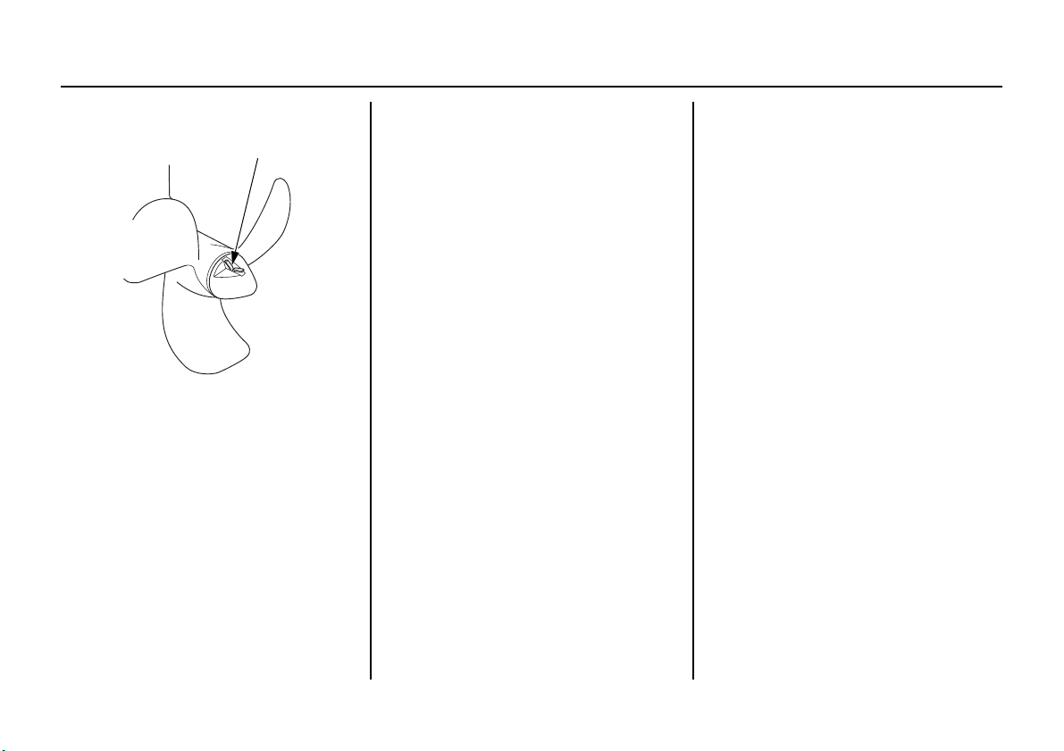
SERVICING YOUR OUTBOARD MOTOR
COTTER PIN
Installation
1. Install the shear pin and the
propeller, then install the propeller
cap finger tight.
2. Be sure to replace the cotter pin
with a new one.
• Use a Honda Genuine stainless
steel cotter pin or equivalent cotter
pin and bend the pin ends as
shown.
Spare shear pin and cotter pin are
provided in the engine compartment
(p. 60).
80

CLEANING AND FLUSHING
FLUSH KIT
(Optional Equipment)
WATER MOUTH
NUT
WATER HOSE
CONNECTOR
WATER
MOUTH
SEAT
Cleaning and Flushing
After each use in salt water or dirty
water, thoroughly clean and flush the
outboard motor with fresh water.
Cleaning
Wash the outside of the outboard
motor with clean, fresh water to
remove mud, salt, seaweed, etc.
Disengage the emergency stop switch
clip from the emergency stop switch,
and pull the recoil starter rope several
times to expel any water remaining in
the water pump.
Touch up any damaged paint, and
coat areas that may rust with Honda
Corrosion Inhibitor, or equivalent.
Lubricate controls with a silicone
spray lubricant.
Flushing With the Honda Water
Hose Connector
1. Tilt down the outboard motor
(p. 56).
2. Remove the flush screw from the
WASH screw hole and install the
water hose connector.
3. Attach a hose from a fresh water
faucet to the water hose connector
of the flush kit.
4. Remove the propeller (p. 79).
5. Turn on the fresh water supply to
hose.
6. Start the engine and run in N
(neutral) for 10 minutes.
81

CLEANING AND FLUSHING
WATER HOSE
WATER HOSE
CONNECTOR
7. After flushing, when using the
internal fuel tank, close the internal
fuel tank vent by turning the vent
knob clockwise all the way (p. 21),
turn the fuel valve lever to the OFF
position (BF4A) or portable fuel
tank position (BF5D and BF6A) (p.
19) and leave the outboard motor in
the running position for one minute
to drain the water from inside the
engine.
After flushing, when using the
portable fuel tank (BF5D and
BF6A), turn the portable fuel tank
vent knob counterclockwise to the
open position (p. 26), disconnect
the fuel hose connectors from the
outboard motor and portable fuel
tank (p. 40), install fuel hose
connector cap, close the internal
fuel tank vent by turning the vent
knob clockwise all the way (p. 21),
close the portable fuel tank vent by
turning the vent knob clockwise all
the way (p. 26) and leave the
outboard motor in the running
position for one minute to drain the
water from inside the engine.
8. Reinstall the flush screw and the
propeller (p. 80).
9. Tilt up the outboard motor (p. 57).
82

CLEANING AND FLUSHING
ANTIVENTILATION PLATE
Flushing Without the Honda
Water Hose Connector
It is necessary to run the engine
during the flushing procedure. For
safety, remove the propeller from the
outboard motor (p. 79).
1. Tilt down the outboard motor
(p. 56).
2. Place a container under the
outboard motor, and fill it with
clean, fresh water. The water level
must be at least 2 inches (5 cm)
above the antiventilation plate.
Running the engine without good
water circulation can cause
overheating and water pump
damage.
Damage caused by running the
outboard motor without sufficient
cooling water is not covered by the
Distributor’s Limited Warranty (U.S.) /
Distributor’s Warranty (CA.)
3. Start the engine and run in the N
(neutral) position at low speed for
at least 10 minutes.
4. After flushing, when using the
internal fuel tank, close the internal
fuel tank vent by turning the vent
knob clockwise all the way (p. 21),
turn the fuel valve lever to the OFF
position (BF4A) or portable fuel
tank position (BF5D and BF6A) (p.
19) and leave the outboard motor in
the running position for one minute
to drain the water from inside the
engine.
(p. 112).
After flushing, when using the
portable fuel tank (BF5D and
BF6A), turn the portable fuel tank
vent knob counterclockwise to the
open position (p. 26), disconnect
the fuel hose connectors from the
outboard motor and portable fuel
tank (p. 40), install fuel hose
connector cap, close the internal
fuel tank vent by turning the vent
knob clockwise all the way (p. 21),
close the portable fuel tank vent by
turning the vent knob clockwise all
the way (p. 26) and leave the
outboard motor in the running
position for one minute to drain the
water from inside the engine.
5. Reinstall the propeller (p. 80).
6. Tilt up the outboard motor (p. 57).
83

STORAGE
Fuel
Depending on the region where you
operate your outboard, fuel
formulations may deteriorate and
oxidize rapidly. Fuel deterioration
and oxidation can occur in as little as
15 days and may cause damage to the
carburetor and fuel system.
Please check with your servicing
dealer for local storage
recommendations.
Gasoline will oxidize and deteriorate
in storage. Deteriorated gasoline will
cause hard starting, and it leaves gum
deposits that clog the fuel system. If
the gasoline in your fuel tank and
carburetor deteriorates during
storage, you may need to have the
carburetor and other fuel system
components serviced or replaced.
The length of time that gasoline can
be left in your fuel tank and
carburetor without causing functional
problems will vary with such factors
as gasoline blend, your storage
temperatures, and whether the fuel
tank is partially or completely filled.
The air in a partially filled fuel tank
promotes fuel deterioration. Very
warm storage temperatures accelerate
fuel deterioration. Fuel deterioration
problems may occur in less than 15
days, if the gasoline was not fresh
when you filled the fuel tank.
You can extend fuel storage life by
adding a gasoline stabilizer that is
formulated for that purpose, or you
can avoid fuel deterioration problems
by draining all the fuel from the fuel
tank and carburetor.
The
Distributor’s Limited Warranty (U.S.)
/ Distributor’s Warranty (CA.)
does not cover fuel system damage or
engine performance problems resulting
from neglected storage preparation.
(p. 112)
Adding a Fuel Stabilizer
When adding a fuel stabilizer, fill the
internal fuel tank with fresh gasoline.
If only partially filled, air in the
internal fuel tank will promote fuel
deterioration during storage. If you
keep an additional container of
gasoline for refueling, be sure that it
contains only fresh gasoline.
1. Add Honda Marine fuel stabilizer
or equivalent following the
instructions on the label.
2. After adding a fuel stabilizer, run
the engine in water for 10 minutes
to be sure that the treated gasoline
has replaced the untreated gasoline
in the carburetor.
3. Stop the engine (p. 51).
84

STORAGE
CARBURETOR
DRAIN PORT
AIR GUIDE
DRAIN
SCREW
DRAIN
TUBE
ENGINE UNDER COVER
Draining the Fuel System
You can avoid fuel deterioration
problems by draining the fuel tank
and carburetor.
1. When using the portable fuel tank
(BF5D and BF6A), turn the portable
fuel tank vent knob
counterclockwise to the open
position (p. 26), disconnect the fuel
hose connectors from the outboard
motor and portable fuel tank (p. 40),
install fuel hose connector cap,
remove the portable fuel filler cap,
drain the gasoline from the portable
fuel tank into a suitable container,
install the portable fuel filler cap
and close the portable fuel tank vent
by turning the vent knob clockwise
all the way (p. 26).
Gasoline is highly flammable and
explosive.
You can be burned or seriously
injured when handling fuel.
• Stop the engine and let it cool
before handling fuel.
• Keep heat, sparks, and flame
away.
• Handle fuel only outdoors.
• Keep away from your vehicle.
• Wipe up spills immediately.
2. Turn the internal fuel tank vent
knob counterclockwise to the open
21
position (p.
), remove the fuel
filler cap, and drain the gasoline
from the internal fuel tank into a
suitable container.
3. Install the fuel filler cap.
4. Turn the fuel valve lever to the
OFF position (BF4A) or portable
fuel tank position (BF5D and
19
BF6A) (p.
).
5. Unlock and remove the engine
cover (p.
63
).
6. Disconnect the drain tube from the
air guide, then connect it to the
carburetor drain port as shown.
7. With the outboard motor in a
vertical position, place an approved
gasoline container below the fuel
drain outlet, and use a funnel to
avoid spilling fuel.
Loosen the drain screw to drain
fuel from the carburetor.
85

STORAGE
8. After the fuel has drained from the
carburetor, tighten the drain screw
securely.
9. Reconnect the drain tube to the air
guide and the engine under cover.
10.Close the internal fuel tank vent
by turning the vent knob
21
clockwise all the way (p.
11.Turn the fuel valve lever to the
OFF position (BF4A) or portable
fuel tank position (BF5D and
19
BF6A) (p.
).
).
12.If you need to store fuel in the fuel
tank, you can extend fuel storage
life by filling the fuel tank with
fresh gasoline and adding Honda
Marine fuel stabilizer or
equivalent following the directions
on the container (p.
Store the portable fuel tank in a cool
dry place out of direct sunlight.
84
).
(When using the internal fuel
tank)
When starting the engine after
draining the gasoline, prime the
37
carburetor with gasoline (p.
).
Engine Oil
Change the engine oil (p. 65).
Engine Cylinder
1. Remove the spark plug (p. 70), and
remove the emergency stop switch
clip from the emergency stop switch.
2. Pour 1 – 2 teaspoons (5 – 10 cm3) of
clean engine oil into the cylinder.
3. Pull the starter grip several times to
distribute the oil in the cylinder.
When cranking the engine with an open
ignition circuit (spark plug removed
from the ignition circuit), remove the
emergency stop switch clip from the
emergency stop switch to prevent
possible damage to the ignition system.
4. Reinstall the spark plug and
connect the spark plug cap (p. 71).
5. Install the engine cover (p. 63), and
lock it in place by locking the
engine cover latch.
86

STORAGE
CARRYING HANDLE
STORAGE PRECAUTIONS
Select a well-ventilated storage area.
If possible, avoid storage areas with
high humidity.
Disconnect the battery charge cable
(equipped type) (p. 29).
To carry the outboard motor, hold it
by the carrying handle, or hold by the
carrying handle and the lug beneath
the engine under cover, as shown.
Lifting the outboard motor by the
engine cover, or using the installed
outboard motor as a handle or lever
to move the boat, can damage the
outboard motor.
If your internal fuel tank and portable
fuel tank contains gasoline, store it
away from any appliance that
operates with a flame, such as a
furnace, water heater, or clothes
dryer. Also avoid any area with a
spark-producing electric motor, or
where power tools are operated.
Store the outboard motor either
vertically or horizontally with the
tiller handle side up and move the
shift lever to the R (reverse) position
to lock the tilt system.
87

STORAGE
CASE PROTECTORS
REMOVAL FROM STORAGE
If storing horizontally, be sure to fold
the tiller handle, and rest the outboard
motor on its case protectors.
Be sure all water has drained from the
outboard motor before placing it on
its side, so no residual water can enter
the engine exhaust port.
• Any other horizontal storage
position may cause damage to the
outboard motor or oil leakage.
• Position the outboard motor so that
the engine side is higher than the
propeller side. Failure to do so may
cause engine oil leakage.
Cover the outboard motor to keep out
dust. Do not use a plastic sheet as a
dust cover. A nonporous cover will
trap moisture, promoting rust and
corrosion.
Check your outboard motor as
described in the
OPERATION
If the cylinder was coated with oil
during storage preparation, the engine
may smoke briefly at startup.
This is normal.
BEFORE
chapter of this manual.
88

TRANSPORTING
OUTBOARD MOTOR SUPPORT BAR
(commercially available)
WITH OUTBOARD MOTOR INSTALLED ON BOAT
When using the portable fuel tank
(BF5D and BF6A), turn the portable
fuel tank vent knob counterclockwise
to the open position (p. 26),
disconnect the fuel hose connectors
from the outboard motor and portable
fuel tank (p. 40), install fuel hose
connector cap and close the portable
fuel tank vent by turning the vent
knob clockwise all the way (p. 26).
Drain the internal fuel tank and
carburetor as described on p. 85, turn
the fuel valve lever to the OFF
position (BF4A) or portable fuel tank
position (BF5D and BF6A) (p. 19),
close the internal fuel tank vent by
turning the vent knob clockwise all
the way (p. 21), move the shift lever
to the R (reverse) position to lock the
tilt system and tighten the steering
friction bolt securely (p. 54).
The preferred method is to leave the
engine in the normal running
position, but if there is insufficient
road clearance, you can tilt the
outboard motor using a commercially
available outboard motor support bar
available through your dealer. Refer
to the manufacturer’s instructions for
using an outboard motor support bar.
89

TRANSPORTING
CARRYING HANDLE
WITH OUTBOARD MOTOR REMOVED FROM BOAT
Disconnect the battery charge cable
(equipped type) (p. 29).
When using the portable fuel tank
(BF5D and BF6A), turn the portable
fuel tank vent knob counterclockwise
to the open position (p. 26),
disconnect the fuel hose connectors
from the outboard motor and portable
fuel tank (p. 40), install fuel hose
connector cap and turn the portable
fuel tank vent knob clockwise all the
way (p. 26).
Drain the internal fuel tank and
carburetor as described on p. 85, turn
the fuel valve lever to the OFF
position (BF4A) or portable fuel tank
position (BF5D and BF6A) (p. 19),
close the internal fuel tank vent by
turning the vent knob clockwise all
the way (p. 21), move the shift lever
to the R (reverse) position to lock the
tilt system and tighten the steering
friction bolt securely (p. 54).
Remove the outboard motor from the
boat and secure the outboard motor in
either the vertical or horizontal
position shown on p. 88.
To carry, hold the outboard motor by
the carrying handle, or hold by the
carrying handle and the lug beneath
the engine under cover, as shown.
Lifting the outboard motor by the
engine cover, or using the installed
outboard motor as a handle or lever
to move the boat, can damage the
outboard motor.
90

TAKING CARE OF UNEXPECTED PROBLEMS
Starting After Starting
18°
ENGINE WILL NOT START
Possible Cause Correction
Clip not inserted in emergency stop switch. Insert clip in emergency stop switch.
Gearshift lever not in neutral position. Shift to neutral (p. 41).
Choke OFF. Pull choke knob to ON position, unless engine is warm
(p. 44).
Throttle grip not in START position. Turn throttle grip to START position (p. 44).
Engine ran out of fuel. Refill fuel tank (p. 71). Perform the priming procedure
after refilling the tank (p. 37). Pull choke knob (p. 44).
Engine is at negative trim angle. Tilt the engine up to the first shallow water drive position
(p. 56).
Return engine to normal operating position after starting
(p. 57).
91

TAKING CARE OF UNEXPECTED PROBLEMS
ENGINE WILL NOT START
Possible Cause Correction
Out of fuel. Refuel (p. 71).
Fuel valve lever is not turned to the appropriate position.
Fuel vent closed (internal fuel tank).
When using the portable fuel tank (BF5D and BF6A), fuel
vent closed (portable fuel tank).
When using the portable fuel tank (BF5D and BF6A), fuel
hose not primed.
Fuel filter or fuel tank f ilter restricted. Replace restricted filters (p. 75 or 77).
Bad fuel; outboard motor stored without treating or
draining gasoline, or refueled with bad gasoline.
Spark plug faulty, fouled, or improperly gapped.
Spark plug wet with fuel (flooded engine). Dry and reinstall spark plug. Start engine with choke and
Carburetor malfunction, fuel pump failure, ignition
malfunction, stuck valves, etc.
Turn the fuel valve lever to the appropriate position
(p. 19).
Turn the internal fuel tank vent knob counterclockwise to
the open position (p. 21).
Turn the portable fuel tank vent knob counterclockwise to
the open position (p. 26).
Squeeze priming bulb (p. 40).
Drain fuel tank and carburetor (p. 85). Refill with fresh
gasoline (p. 71).
Adjust the spark plug electrode gap or replace spark plug
(p. 70).
throttle open.
Take outboard motor to an authorized Marine dealer, or
refer to the shop manual.
92

TAKING CARE OF UNEXPECTED PROBLEMS
HARD STARTING OR STALLS AFTER STARTING
Possible Cause Correction
Choke OFF. Pull choke knob to ON position, unless engine is warm
(p. 44).
Throttle grip not in START position. Turn throttle grip to START position (p. 44).
Fuel valve lever is not turned to the appropriate position.
Fuel vent closed (internal fuel tank).
When using the portable fuel tank (BF5D and BF6A), fuel
vent closed (portable fuel tank).
When using the portable fuel tank (BF5D and BF6A), fuel
hose not primed.
Fuel filter or fuel tank f ilter restricted. Replace restricted filters (p. 75 or 77).
Bad fuel; outboard motor stored without treating or
draining gasoline, or refueled with bad fuel.
Turn the fuel valve lever to the appropriate position
(p. 19).
Turn the internal fuel tank vent knob counterclockwise to
the open position (p. 21).
Turn the portable fuel tank vent knob counterclockwise to
the open position (p. 26).
Squeeze priming bulb (p. 40).
Drain fuel tank and carburetor (p. 85). Refill with fresh
gasoline (p. 71).
93

TAKING CARE OF UNEXPECTED PROBLEMS
HARD STARTING OR STALLS AFTER STARTING
Possible Cause Correction
Spark plug faulty, fouled, or improperly gapped.
Carburetor malfunction, fuel pump failure, ignition
malfunction, etc.
ENGINE OVERHEATS
Possible Cause Correction
Water intakes clogged. Clean water intakes.
Faulty thermostat or water pump. Take outboard motor to an authorized Marine dealer, or
Adjust the spark plug electrode gap or replace spark plug
(p. 70).
Take outboard motor to an authorized Marine dealer, or
refer to the shop manual.
refer to the shop manual.
94

TAKING CARE OF UNEXPECTED PROBLEMS
ENGINE WILL NOT DRIVE THE PROPELLER
Possible Cause Correction
Broken shear pin. Replace shear pin (p. 79).
Damaged gearshift mechanism. Take outboard motor to an authorized Marine dealer, or
refer to the shop manual.
95

TAKING CARE OF UNEXPECTED PROBLEMS
SPARE FUSE
FUSE HOLDER
FUSE
FUSE CASE LID
BLOWN FUSE
BATTERY WILL NOT CHARGE (Equipped type)
The battery-charging circuit is
protected by the 15-ampere fuse.
Fuse Replacement
1. Stop the engine.
2. Remove and inspect the fuse. If a fuse
is burnt out, install a replacement fuse
of the specified rating. The outboard
motor is supplied with a spare fuse in
fuse holder.
DESIGNATED FUSE RATING:
15A
Never use a fuse with a rating greater
than specified. Serious damage to the
electrical system could result.
3. Reinstall the fuse case lid.
Before further operation, try to
determine and correct the electrical
problem that caused the fuse to burn
out. An uncorrected electrical
problem may cause the fuse to burn
out again.
96

TAKING CARE OF UNEXPECTED PROBLEMS
OIL PRESSURE
INDICATOR
OIL PRESSURE INDICATOR GOES OFF AND ENGINE SPEED IS LIMITED
If oil pressure becomes low, the green
indicator will go off. If you are at
cruising speed, engine speed will
decrease gradually.
Low oil pressure may be the result of
a low engine oil level, or there may
be a problem with the engine
lubrication system.
If the throttle is closed suddenly after
full throttle operation, engine speed
may drop below the specified idle
rpm, and that could activate the
engine protection system
momentarily.
If low oil pressure activates the
engine protection system, stop the
engine, check the engine oil level
(p. 64), and add oil if needed.
With the engine oil at the
recommended level, restart the
engine. If the lubrication system is
OK, the green indicator should come
on within 30 seconds, and the engine
will respond normally to throttle grip
operation.
If the engine protection system
remains activated after 30 seconds,
return to the nearest boat landing, and
have the outboard motor inspected by
an authorized Marine dealer.
97

TAKING CARE OF UNEXPECTED PROBLEMS
STARTER GRIP
SUBMERGED OUTBOARD MOTOR
A submerged outboard motor must be
serviced immediately after it is
recovered from the water in order to
minimize corrosion.
If there is a Honda Marine dealership
nearby, take the outboard motor to the
dealer immediately. If you are far
from a dealer, proceed as follows:
1. Unlock and remove the engine
cover (p. 63), and rinse the
outboard motor with fresh water to
remove salt water, sand, mud, etc.
2. Drain the internal fuel tank and
carburetor as described on p. 85.
3. Change the engine oil as described
on p. 65. If there was water in the
engine crankcase, or if the used
engine oil showed signs of water
contamination, then a second
engine oil change should be
performed after running the engine
for half an hour.
4. Remove the spark plug (p. 70), and
remove the emergency stop switch
clip from the emergency stop
switch. Pull the starter grip, rotate
the flywheel a few revolutions to
completely expel any water from
the cylinder.
If the engine was running when it
submerged, there may be
mechanical damage, such as a bent
connecting rod. If the engine binds
when cranked, do not attempt to
run the engine until it has been
repaired.
When cranking the engine with an
open ignition circuit (spark plug
removed from the ignition circuit),
remove the emergency stop switch
clip from the emergency stop switch
to prevent possible damage to the
ignition system.
98
 Loading...