


Owner`s Manual
BF200D • BF225D •
BF250D
Includes US and Canadian Models
© 2022 Honda Motor Co., Ltd. - All Rights Reserved

The engine exhaust from this
product contains chemicals
known to the State of California to
cause cancer, birth defects, or
other reproductive harm.
Keep this Owner’s Manual handy, so you can refer to it at any time. This Owner’s
Manual is considered a permanent part of the outboard motor and should remain with
the outboard motor if resold.
The information and specifications included in this publication were in effect at the
time of approval for printing. Honda Motor Co., Ltd. reserves the right, however, to
discontinue or change specifications or design at any time without notice and without
incurring any obligation whatever. No part of this publication may be reproduced
without written permission.

INTRODUCTION
Congratulations on your selection of
a Honda outboard motor. We are
certain you will be pleased with your
purchase of one of the finest outboard
motors on the market.
We want to help you get the best
results from your new outboard motor
and to operate it safely. This manual
contains information on how to do
that; please read it carefully.
As you read this manual you will find
information preceded by a
symbol. That information is intended
to help you avoid damage to your
outboard motor, other property, or the
environment.
We suggest you read the warranty
policy to fully understand its
coverage and your responsibilities of
ownership.
When your outboard motor needs
scheduled maintenance, keep in mind
that your Honda Marine dealer is
specially trained in servicing Honda
outboard motors. Your Honda Marine
dealer is dedicated to your
satisfaction and will be pleased to
answer your questions and concerns.
1

INTRODUCTION
A FEW WORDS ABOUT
SAFETY
Your safety and the safety of others
are very important. And using this
outboard motor safely is an important
responsibility.
To help you make informed decisions
about safety, we have provided
operating procedures and other
information on labels and in this
manual. This information alerts you
to potential hazards that could hurt
you or others.
Of course, it is not practical or
possible to warn you about all the
hazards associated with operating or
maintaining an outboard motor. You
must use your own good judgment.
You will find important safety information in a variety of forms, including:
•Safety Labels – on the outboard motor.
• Safety Messages – preceded by a safety alert symbol and one of three
signal words, DANGER, WARNING, or CAUTION.
These signal words mean:
You WILL be KILLED or SERIOUSLY
HURT if you don’t follow instructions.
You CAN be KILLED or SERIOUSLY
HURT if you don’t follow instructions.
You CAN be HURT if you don’t follow
instructions.
• Safety Headings – such as IMPORTANT SAFETY INFORMATION.
• Safety Section – such as OUTBOARD MOTOR SAFETY.
• Instructions – how to use this outboard motor correctly and safely.
This entire manual is filled with important safety information – please read it
carefully.
2

CONTENTS
OUTBOARD MOTOR SAFETY ................................... 7
IMPORTANT SAFETY INFORMATION .............. 7
SAFETY LABEL LOCATION ................................ 9
CONTROLS AND FEATURES ................................... 10
CONTROL AND FEATURE IDENTIFICATION
CODES ................................................................ 10
HOW TO DETERMINE WHICH DIRECTION
THE PROPELLER SHAFT ROTATES ............. 11
COMPONENT AND CONTROL LOCATIONS ... 12
CONTROLS ............................................................ 21
Flush-Mount Type/Top-Mount Type
(DBW type) ......................................................... 21
Ignition Switch
(without START/STOP switch) ...................... 21
Power Switch
(with START/STOP switch) ........................... 22
Honda Smart Key ................................................ 22
START/STOP Switch ......................................... 23
Emergency Stop Switch Clip and Emergency
Stop Switch ..................................................... 24
Gearshift/Throttle Control Lever
(Flush-Mount type) ......................................... 25
Gearshift/Throttle Control Lever
(Top-Mount type (DBW type)) ....................... 26
Function Switches
(Flush-Mount type) ......................................... 27
Function Switches
(Single Top-Mount type (DBW type)) ............28
Side-Mount Type .....................................................30
Ignition Switch ....................................................30
Emergency Stop Switch Clip and Emergency
Stop Switch ......................................................31
Gearshift/Throttle Control Lever .........................31
Fast Idle Lever .....................................................33
Flush-Mount Type (Mechanical wire type) .............33
Ignition Switch ....................................................33
Emergency Stop Switch Clip and Emergency
Stop Switch ......................................................34
Gearshift/Throttle Control Lever .........................35
Fast Idle Button ...................................................36
Top-Mount Type (Mechanical wire type) ...............37
Ignition Switch ....................................................37
Emergency Stop Switch Clip and Emergency
Stop Switch ......................................................37
Gearshift/Throttle Control Lever .........................38
Fast Idle Button ...................................................39
Common Controls ....................................................40
Power Trim/Tilt Switch .......................................40
PTT Switch Panel ................................................42
Power Tilt Switch ................................................42
Manual Relief Valve ............................................42
Tilt Lock Lever ....................................................43
Engine Cover Latches ..........................................43
3

CONTENTS
Trim Tab .............................................................. 43
INSTRUMENTS ..................................................... 44
Trim Meter (standard or optionally applicable
equipment) ...................................................... 44
Tachometer (standard or optionally applicable
equipment) ...................................................... 44
NMEA Interface Coupler .................................... 44
Operating Hour Notification System .................. 45
INDICATORS ......................................................... 47
Alternator (ACG) Indicator ................................. 47
Malfunction Indicator .......................................... 48
Oil Pressure Indicator .......................................... 49
Overheat Indicator ............................................... 49
Cooling System Indicator .................................... 50
OTHER FEATURES .............................................. 50
Water Separator Buzzer ...................................... 50
Rev Limiter ......................................................... 51
Anodes ................................................................. 51
Fuel Priming Bulb ............................................... 51
BEFORE OPERATION ................................................ 52
ARE YOU READY TO GET UNDERWAY? ....... 52
IS YOUR OUTBOARD MOTOR
READY TO GO? ................................................ 52
OPERATION ................................................................ 54
SAFE OPERATING PRECAUTIONS ................... 54
BREAK-IN PROCEDURE .....................................54
FUEL PRIMING .....................................................55
INFREQUENT OR OCCASIONAL USE ..............55
STARTING THE ENGINE .....................................56
Flush-Mount Type/Top-Mount Type
(DBW type) .....................................................56
Side-Mount Type .................................................59
Flush-mount type (Mechanical wire type) ...........62
Top-Mount Type (Mechanical wire type) ...........64
Station Select Mode .................................................67
STOPPING THE ENGINE ......................................67
Emergency Engine Stopping ...............................67
Normal Engine Stopping
(Flush-Mount Type, Top-Mount Type
(DBW type)) ....................................................68
Normal Engine Stopping
(Side-Mount Type, Flush-Mount Type,
Top-Mount Type (Mechanical wire type)) ...... 70
GEARSHIFT AND
THROTTLE OPERATION .................................72
STEERING ..............................................................74
CRUISING ..............................................................75
TROLLING MODE .................................................78
ONE-LEVER MODE ..............................................79
SHALLOW WATER OPERATION .......................79
MOORING, BEACHING, LAUNCHING ..............80
MULTIPLE OUTBOARD MOTORS .....................81
4

CONTENTS
SERVICING YOUR OUTBOARD MOTOR ............... 82
THE IMPORTANCE OF MAINTENANCE .......... 82
MAINTENANCE SAFETY ................................... 83
TOOL KIT and OWNER’S MANUAL .................. 84
SPARE EMERGENCY STOP SWITCH CLIP
(applicable types) ................................................ 84
MAINTENANCE SCHEDULE .............................. 85
TRIM TAB ADJUSTMENT ................................... 87
MANUAL RELIEF VALVE .................................. 88
ENGINE COVER REMOVAL AND
INSTALLATION ................................................ 88
Engine Oil Level Check .......................................... 89
Engine Oil Change .................................................. 91
Oil Filter Change ..................................................... 92
Engine Oil Recommendations ................................. 93
Lubrication Points ................................................... 94
Spark Plug Service .................................................. 95
REFUELING ........................................................... 99
FUEL RECOMMENDATIONS ........................... 100
Fuel Filter with Water Separator Inspection and
Replacement ...................................................... 100
Anode Replacement .............................................. 104
Propeller Replacement .......................................... 105
Inspect After Operating ......................................... 106
CLEANING AND FLUSHING ...................................107
Cleaning and Flushing ...........................................107
STORAGE ...................................................................109
Fuel ....................................................................109
Engine Oil ..........................................................111
HOISTING THE OUTBOARD MOTOR .............112
STORAGE PRECAUTIONS ................................112
REMOVAL FROM STORAGE ............................113
TRANSPORTING .......................................................114
WITH OUTBOARD MOTOR
INSTALLED ON BOAT ...................................114
WITH OUTBOARD MOTOR
REMOVED FROM BOAT ...............................114
5

CONTENTS
TAKING CARE OF UNEXPECTED PROBLEMS ... 115
ENGINE WILL NOT START .............................. 115
HARD STARTING OR STALLS AFTER
STARTING ....................................................... 118
ENGINE OVERHEATS ....................................... 119
FUSES ................................................................... 120
Electric Starter Will Not Operate ...................... 120
Battery Will Not Charge ................................... 120
Fuse Replacement ............................................. 120
OIL PRESSURE INDICATOR GOES OFF AND
ENGINE SPEED IS LIMITED ......................... 123
OVERHEAT INDICATOR COMES ON AND
ENGINE SPEED IS LIMITED ......................... 124
WATER SEPARATOR BUZZER SOUNDS ....... 125
SUBMERGED OUTBOARD MOTOR ................ 126
Emergency Gear Shifting (for DBW type) ........... 128
TECHNICAL INFORMATION ................................. 129
Serial Number Locations ....................................... 129
Battery ................................................................... 130
Emission Control System Information .................. 131
Star Label .............................................................. 134
Specifications ........................................................ 136
CONSUMER INFORMATION ..................................142
Dealer Locator Information ...................................142
Honda Publications ............................................142
Customer Service Information ...............................143
Warranty Statements ..............................................145
Distributor’s Limited Warranty .............................145
Emission Control System Warranty ......................150
Distributor’s Warranty ...........................................155
INDEX .........................................................................158
6

OUTBOARD MOTOR SAFETY
IMPORTANT SAFETY INFORMATION
The Honda BF200D, BF225D, and
BF250D outboard motors are
designed for use with boats that have
a suitable manufacturer’s power
recommendation. Other uses can
result in injury to the operator or
damage to the outboard motor and
other property.
Most injuries or property damage can
be prevented if you follow all
instructions in this manual and on the
outboard motor. The most common
hazards are discussed in this chapter,
along with the best way to protect
yourself and others.
Operator Responsibility
• It is the operator’s responsibility to
provide the necessary safeguards to
protect people and property. Know
how to stop the engine quickly in
case of emergency. Understand the
use of all controls.
• Stop the engine immediately if
anyone falls overboard, and do not
run the engine while the boat is
near anyone in the water.
• Always stop the engine if you must
leave the controls for any reason.
• Attach the emergency stop switch
lanyard securely to the operator.
• Always wear a PFD (Personal
Flotation Device) while on the
boat.
• Familiarize yourself with all laws
and regulations relating to boating
and the use of outboard motors.
• Be sure that anyone who operates
the outboard motor receives proper
instruction.
• Be sure the outboard motor is
properly mounted on the boat.
• Do not remove the engine cover
while the engine is running.
7

OUTBOARD MOTOR SAFETY
Refuel With Care
• Gasoline is extremely flammable,
and gasoline vapor can explode.
Refuel outdoors, in a
well-ventilated area, with the
engine stopped. Never smoke near
gasoline, and keep other flames and
sparks away.
• Refuel carefully to avoid spilling
fuel. Avoid overfilling the fuel
tank.
• After refueling, tighten the filler
cap securely. If any fuel is spilled,
make sure the area is dry before
starting the engine.
Carbon Monoxide Hazard
Exhaust contains poisonous carbon
monoxide, a colorless, odorless gas.
Breathing carbon monoxide can
cause loss of consciousness and may
lead to death.
If you run the engine in an area that is
confined, or even partly enclosed, the
air you breathe could contain a
dangerous amount of exhaust gas.
Never run your outboard inside a
garage or other enclosure.
Running the engine of your
outboard while in an enclosed or
partially enclosed area can cause
a rapid build-up of toxic carbon
monoxide gas.
Breathing this colorless, odorless
gas can quickly cause un
consciousness and lead to death.
Only run your outboard engine
when it is located in a well
ventilated area outdoors.
8

OUTBOARD MOTOR SAFETY
Canadian Types
(2) Canadian Types only
*: Canadian types only
(1)
(2)
*
• Honda outboard motor is
designed to give safe and
dependable service if operated
according to instructions.
Read and understand the
Owner’s Manual before
operating the outboard motor.
Failure to do so could result in
personal injury or equipment
damage.
SAFETY LABEL LOCATION
(1) US, Puerto Rico, and US Virgin Islands Types
The labels shown here contain important safety information. Please read them
carefully. These labels are considered permanent parts of your outboard motor.
If a label comes off or becomes hard to read, contact an authorized Marine
dealer for a replacement.
Canadian Types
9

CONTROLS AND FEATURES
TYPE CODE (example)
LCR□
Destination
Remote Control
R: Mechanical wire D: Drive by Wire (DBW)
Rotating direction of propeller shaft
C: Counterrotating propeller shaft
None: Standard rotating propeller shaft
Transom Height
L: 20.0 in (508 mm), X: 25.0 in (635 mm), U: 30.0 in (762 mm)
CONTROL AND FEATURE IDENTIFICATION CODES
Model BF200D BF225D BF250D
Type LR□ LD□ XR□ XD□
XCR□ XCD□
LR□ LD□ XR□ XD□
XCR□ XCD□
UR□ UD□
UCR□ UCD□
LR□ LD□ XR□ XD□
XCR□ XCD□
UR□ UD□
UCR□ UCD□
Transom
Height
Standard Rotating Propeller Shaft
Counterrotating Propeller Shaft
Mechanical wire •••••••••••••
Drive by Wire (DBW) •••••••••••••
Refer to this chart for an explanation of the Type Codes used in this manual to identify control and feature applications.
For the detailed equipment conditions of optional components, consult your Honda dealer.
10
20.0 in (508 mm)
25.0 in (635 mm)
30.0 in (762 mm)
•• •• ••
•••• •••• ••••
•••• •••• •• •••• ••
•• •• •• •• ••
•••• ••••

HOW TO DETERMINE
WITHOUT
GROOVE
WITH
GROOVE
GROOVE
WHICH DIRECTION THE
PROPELLER SHAFT
ROTATES
The direction the propeller shaft
rotates can be determined based on
whether or not the shaft has a groove.
With groove: Counterrotating
Without groove: Standard rotating
CONTROLS AND FEATURES
11

CONTROLS AND FEATURES
ENGINE COVER
ENGINE COVER LATCH
STERN BRACKET
MANUAL RELIEF
VA LV E
ANODE
PROPELLER
ANTIVENTILATION PLATE
ANODE
IDLE PORT
FLUSH PLUG
CONNECTOR
COOLING
SYSTEM
INDICATOR
TRIM TAB
ENGINE COVER LATCH
(each side)
ENGINE OIL
DRAIN BOLT
EXHAUST PORT/
WATER OUTLET PORT
FRAME SERIAL
NUMBER
ANODE
COOLING WATER INTAKE PORT
(each side)
POWER TILT SWITCH
TILT LOCK LEVER
COMPONENT AND CONTROL LOCATIONS
* Illustrations are based on X type
12

SPARK PLUGS
(under coil)
OIL LEVEL DIPSTICK
FUEL FILTER with
WATER SEPARATOR
(Mechanical wire type)
THROTTLE ARM/SHIFT
ARM SHAFT
IGNITION COIL GUARD
CONTROLS AND FEATURES
13

CONTROLS AND FEATURES
NMEA INTERFACE COUPLER
JUNCTION BOX
(FUSES)
OIL FILLER CAP
IGNITION COIL GUARD
(Mechanical wire type)
THROTTLE REEL
14

DBW Remote Control Box (SINGLE TOP-MOUNT REMOTE CONTROL)
GEARSHIFT/
THROTTLE
CONTROL LEVER
NEUTRAL RELEASE
LEVER
POWER TRIM/TILT
SWITCH
POWER TRIM/TILT
SWITCH
FUNCTION SWITCHES
(DUAL TOP-MOUNT REMOTE CONTROL)
POWER TRIM/TILT
SWITCH
FUNCTION SWITCHES
GEARSHIFT/
THROTTLE
CONTROL LEVER
GEARSHIFT/
THROTTLE
CONTROL LEVER
(FLUSH-MOUNT REMOTE CONTROL)
(standard or optionally applicable equipment)
CONTROLS AND FEATURES
15

CONTROLS AND FEATURES
POWER
SWITCH
(Normal Key with START/STOP switch type)
(Horizontal type)
(Honda Smart Key type)
(Horizontal type)
EMERGENCY STOP
SWITCH CLIP
EMERGENCY STOP
SWITCH LANYARD
EMERGENCY
STOP SWITCH
POWER SWITCH
IGNITION SWITCH
START/STOP SWITCH
START/STOP SWITCH
ALL ENGINE START
FOR MULTIPLE
OUTBOARD MOTORS
SINGLE TYPE
OUTBOARD MOTOR
START/STOP SWITCH
START/STOP SWITCH
DUAL TYPE
OUTBOARD MOTOR
TRIPLE TYPE
OUTBOARD MOTOR
BUZZER
(Normal Key without START/STOP switch type)
(Horizontal type)
PORT: Port side engine
CENTER: Center engine
STBD: Starboard side engine
Key Switch Panel START/STOP Switch Panel
(standard or optionally applicable equipment) (standard or optionally applicable equipment)
16
$//
67$57
6723
3257
67%'
67$57
67$57
6723
6723
67$57
6723
3257
&(17(5
67$57
67$57
6723
6723
67%'
67$57
6723

CONTROLS AND FEATURES
POWER TRIM/TILT SWITCH
FUNCTION SWITCHES
DUAL TYPE
Emergency Stop Switch Panel
(standard or optionally applicable equipment)
TRIPLE TYPE
EMERGENCY
STOP SWITCH
EMERGENCY STOP
SWITCH CLIP
EMERGENCY STOP
SWITCH LANYARD
Display Assy (standard or optionally applicable equipment)
POWER TRIM/TILT SWITCH
PORT: Port side engine
CENTER: Center engine
STBD: Starboard side engine
PTT Switch Panel Function Switch Panel
(standard or optionally applicable equipment) (standard or optionally applicable equipment)
(for FLUSH-MOUNT type)
:$50
3257 67%'
㼁㻼
㻰㻺
3257 67%'&(17(5
㼁㻼
㻰㻺
㼁㻼
㻰㻺
17
㼁㻼
㻰㻺
)$67,'/(
752// 752//752// 752//752//
㼁㻼
㻰㻺
$&7
752//
EMERGENCY
STOP
STOP
17

CONTROLS AND FEATURES
(SIDE-MOUNT REMOTE CONTROL)
GEARSHIFT/THROTTLE
CONTROL LEVER
POWER TRIM/TILT
SWITCH
BUZZER
(inside)
CONTROL
LEVER
FRICTION
ADJUSTER
EMERGENCY STOP
SWITCH LANYARD
EMERGENCY STOP
SWITCH CLIP
EMERGENCY
STOP SWITCH
IGNITION
SWITCH
FAST IDL E
LEVER
NEUTRAL RELEASE
LEVER
INDICATORS
(Oil pressure, Overheat,
Alternator, Malfunction)
(FLUSH-MOUNT REMOTE CONTROL)
GEARSHIFT/THROTTLE
CONTROL LEVER
POWER TRIM/TILT
SWITCH
FAST IDLE BUTTON
CONTROL PANEL
(for FLUSH-MOUNT type)
BUZZER
EMERGENCY STOP
SWITCH LANYARD
EMERGENCY STOP
SWITCH CLIP
IGNITION
SWITCH
NEUTRAL RELEASE
LEVER
INDICATORS
(Oil pressure, Overheat,
Alternator, Malfunction)
EMERGENCY
STOP SWITCH
Remote Controls (standard or optionally applicable equipment)
18

CONTROLS AND FEATURES
(SINGLE TOP-MOUNT REMOTE CONTROL)
GEARSHIFT/THROTTLE
CONTROL LEVER
POWER
TRIM/ TILT
SWITCH
CONTROL PANEL
(for TOP-MOUNT SINGLE type)
BUZZER
IGNITION
SWITCH
POWER TRIM/
TILT SWITCH
(Left side
operation only)
GEARSHIFT/THROTTLE
CONTROL LEVERS
POWER TRIM/
TILT SWITCH
(Left and right
operations are
interlocked)
(DUAL TOP-MOUNT REMOTE CONTROL)
EMERGENCY STOP
SWITCH CLIP
EMERGENCY STOP
SWITCH LANYARD
EMERGENCY
STOP SWITCH
INDICATORS
(Oil pressure, Overheat,
Alternator, Malfunction)
FAST IDLE BUTTON
(for TOP-MOUNT DUAL type)
FAST IDLE
BUTTON
POWER TRIM/
TILT SWITCH
(Right side
operation only)
19

CONTROLS AND FEATURES
CONTROL PANEL without indicators type
(standard or optionally applicable equipment)
(FLUSH-MOUNT, TOP-MOUNT SINGLE)
IGNITION
SWITCH
KEY
BUZZER
IGNITION SWITCH
EMERGENCY STOP
SWITCH
EMERGENCY STOP
SWITCH CLIP
EMERGENCY STOP SWITCH LANYARD
(for DUAL OUTBOARD
MOTORS type)
(for TRIPLE OUTBOARD
MOTORS type)
For the switch panel without indicators type, use it along with the
NMEA2000-compatible device.
Trim Meter
(standard or optionally
applicable equipment)
Tachometer
(standard or optionally
applicable equipment)
20

CONTROLS AND FEATURES
OFF
ON
START
IGNITION SWITCH KEY
CONTROLS
Flush-Mount Type/Top-Mount Type (DBW type)
Ignition Switch (without START/STOP switch)
The ignition switch controls the
ignition system and the starter motor.
Turning the ignition switch key to the
START position starts the engine.
The key automatically returns to the
ON position when released from the
START position.
The engine will not start unless the
gearshift/throttle control lever is in
the N (neutral) position (p. 56) and
the emergency stop switch clip is in
the emergency stop switch.
Turning the ignition switch to the
OFF position stops the engine.
21

CONTROLS AND FEATURES
POWER SWITCH
ON
OFF
(normal key type)
POWER SWITCH
ON
(Honda Smart Key type)
LOCK BUTTON
Power Switch (with START/STOP switch)
This remote control is equipped with
the power switch. This switch locates
on the key switch panel.
Key positions (For normal key type):
ON: to run the engine after starting.
OFF: to stop the engine
(IGNITION OFF).
For Honda Smart Key type, turning
the power switch to the right switches
the power. The power is turned ON
when it is OFF, and the power is
turned OFF when it is ON.
Do not leave the power switch
ON when the engine is not running
as the battery will discharge.
For Honda Smart Key type, the
power will not be turned ON unless
the Honda Smart Key is
authenticated.
The power will not be turned OFF if
the engine is running.
Honda Smart Key
Use the Honda Smart Key to
authenticate to your remote control
box.
The Honda Smart Key has an
immobilizer system. The immobilizer
system helps to protect against boat
theft.
22

CONTROLS AND FEATURES
START/STOP Switch
START/STOP SWITCH
INDICATOR
ALL ENGINE START
FOR MULTIPLE
OUTBOARD MOTORS
SINGLE TYPE
OUTBOARD MOTOR
START/STOP SWITCH
DUAL TYPE
OUTBOARD MOTORS
TRIPLE TYPE
OUTBOARD MOTORS
START/STOP SWITCH
INDICATOR
67$57
6723
$//
67$57
6723
3257
&(17(5
3257
67%'
67$57
67$57
6723
6723
67$57
6723
67%'
67$57
67$57
6723
6723
Pushing the start/stop switch when
the power is in ON starts the engine.
For the multiple outboard motors, it is
possible to start all engines at the
same time by using the all engine
start switch.
Also, it is possible to start each
engine individually by using dual or
triple type switch.
At this time, the indicator of the
corresponding switch comes on.
The starter motor will not work
unless the gearshift/throttle control
lever is in the NEUTRAL position,
and the clip is in the emergency stop
switch.
23

CONTROLS AND FEATURES
EMERGENCY
STOP SWITCH
EMERGENCY STOP
SWITCH CLIP
EMERGENCY
STOP SWITCH
CLIP
EMERGENCY
STOP SWITCH
LANYARD
EMERGENCY
STOP SWITCH
LANYARD
SPARE SWITCH CLIP
(optional equipment)
Emergency Stop Switch Clip and Emergency Stop Switch
The emergency stop switch clip must
be inserted in the emergency stop
switch in order for the engine to start
and run. The emergency stop switch
lanyard must be attached securely to
the operator or to the operator’s PFD
(Personal Flotation Device).
When used as described, the
emergency stop switch clip and
emergency stop switch lanyard
system stops the engine if the
operator falls away from the controls.
A spare switch clip (optional
equipment) can be stored in the tool
bag.
24

Gearshift/Throttle Control Lever
GEARSHIFT/THROTTLE
CONTROL LEVER
NEUTRAL RELEASE
LEVER
MAXIMUM
F (FORWARD)
SHIFT
20°
N (NEUTRAL)
THROTTLE OPENING
MINIMUM
20°
R (REVERSE)
SHIFT
MINIMUM
THROTTLE OPENING
MAXIMUM
GEARSHIFT/THROTTLE
CONTROL LEVER
(Flush-Mount type)
CONTROLS AND FEATURES
The gearshift/throttle control lever
controls engine speed and selects F
(forward), N (neutral), or R (reverse)
gears.
Moving the control lever 20° from N
(neutral) selects the gear, and further
movement increases engine speed.
The control lever automatically locks
itself in the N (neutral) position. To
move the lever out of the N (neutral)
position, you must squeeze the
neutral release lever on the underside
of the lever handle.
A friction adjuster near the base of
the control lever adjusts the operating
resistance of the control lever. Refer
to p. 73.
Less friction allows easier control
lever movement. More friction helps
to hold a steady throttle setting while
cruising.
25

CONTROLS AND FEATURES
SINGLE TYPE
GEARSHIFT/
THROTTLE
CONTROL
LEVER
DUAL TYPE
GEARSHIFT/THROTTLE
CONTROL LEVERS
MAXIMUM
SHIFT
F (FORWARD)
20°
N (NEUTRAL)
R (REVERSE)
GEARSHIFT/THROTTLE
CONTROL LEVER
THROTTLE OPENING
MINIMUM
THROTTLE OPENING
MINIMUM
SHIFT
20°
MAXIMUM
Gearshift/Throttle Control Lever (Top-Mount type (DBW type))
The gearshift/throttle control lever(s)
controls engine speed and selects F
(forward), N (neutral), or R (reverse)
gears.
26
Moving the control lever 20° from N
(neutral) selects the gear, and further
movement increases engine speed.
A friction adjuster inside the control
box adjusts the operating resistance
of the control lever(s). Refer to p. 73.
Less friction allows easier control
lever movement. More friction helps
to hold a steady throttle setting while
cruising.

CONTROLS AND FEATURES
[-] SWITCH
[+] SWITCH
752// 752//752// 752//752//
)$67,'/(
752//
17
:$50
$&7
NEUTRAL
FORWARD
REVERSE
GEARSHIFT/
THROTTLE
CONTROL
LEVER
NEUTRAL
RELEASE
LEVER
Pull up
Function Switches (Flush-Mount type)
Function switches are used for
operations in the fast idle mode and
trolling mode.
NT (WARM)
Lights: The shift is in neutral.
Blinks: It is in the fast idle mode.
ACT
Lights: The shift and throttle
operations are possible.
Off: The shift and throttle operations
are not possible.
<Fast Idle Mode>
After the engine starts and if the
outside temperature is below 41°F
(5°C), the fast idle mode can be used
to accelerate engine warm up.
See page 58 for engine warm-up
instructions.
Use the [-] switch and the gearshift/
throttle control lever to adjust the
engine speed without gearshift when
warming up the engine.
Keeping the [-] switch pressed when
the gearshift/throttle control lever is
in the NEUTRAL position, turn the
lever forward. Keep turning the lever
forward. The throttle opens and the
engine speed increases after the lever
passed the shift point.
Note that the gearshift mechanism
does not function when the [-] switch
is pushed once and then released after
the gearshift/throttle control lever is
moved.
The control lever does not operate unless
the neutral release lever is pulled.
27

CONTROLS AND FEATURES
[-] SWITCH [+] SWITCH
<Trolling Mode>
The engine speed can be adjusted
with the [-] switch and [+] switch
when in trolling mode.
If you press and hold the [+] switch
while cruising with the throttle
closed, the mode changes to trolling
mode.
Engine speed adjusting range:
650 rpm – 1,000 rpm (every 50 rpm)
To release the trolling mode, press
and hold the [+] switch.
Function Switches (Single Top-Mount type (DBW type))
Function switches are used for
operations in the fast idle mode,
trolling mode, one-lever mode and
station select mode.
NT (WARM)
Lights: The shift is in neutral.
Blinks: It is in the fast idle mode.
ACT
Lights: The shift and throttle
operations are possible.
Off: The shift and throttle operations
are not possible.
<Fast Idle Mode>
After the engine starts and if the
outside temperature is below 41°F
(5°C), the fast idle mode can be used
to accelerate engine warm up.
See page 58 for engine warm-up
instructions.
28

CONTROLS AND FEATURES
NEUTRAL
FORWARD
REVERSE
GEARSHIFT/
THROTTLE
CONTROL
LEVER
PRESS and HOLD
[-] SWITCH
Use the [-] switch and the gearshift/
throttle control lever to adjust the
engine speed without gearshift when
warming up the engine.
Keeping the [-] switch pressed when
the gearshift/throttle control lever is
in the NEUTRAL position, turn the
lever forward. Keep turning the lever
forward. The throttle opens and the
engine speed increases after the lever
passed the shift point.
Note that the gearshift mechanism does
not function when the [-] switch is
pushed once and then released after the
gearshift/throttle control lever is moved.
<Trolling Mode>
The engine speed can be adjusted
with the [-] switch and [+] switch
when in trolling mode.
If you press and hold the [+] switch
while cruising with the throttle closed,
the mode changes to trolling mode.
Engine speed adjusting range:
650 rpm – 1,000 rpm (every 50 rpm)
To release the trolling mode, press
and hold the [+] switch.
<One-Lever Mode>
(For multiple outboard motors type)
Shifting gear and the engine speed
adjustment of the all outboard motors
can be performed with one gearshift/
throttle control lever when in onelever mode.
If you press and hold the [+] switch
when all gearshift/throttle control
lever is in the NEUTRAL position,
the mode changes to one-lever mode.
<Station Select Mode>
For multiple station type, use the [-]
switch to change the operating
station.
If you press and hold the [-] switch of
the inactive station when all gearshift/
throttle control lever is in the
NEUTRAL position, you can operate
the outboard motors using this
station.
29

CONTROLS AND FEATURES
OFF
ON
START
IGNITION SWITCH
Side-Mount Type
Ignition Switch
The ignition switch controls the
ignition system and the starter motor.
Turning the ignition switch key to the
START position starts the engine.
The key automatically returns to the
ON position when released from the
START position.
The engine will not start unless the
gearshift/throttle control lever is in
the N (neutral) position (p. 59) and
the emergency stop switch clip is in
the emergency stop switch.
Turning the ignition switch to the
OFF position stops the engine.
30

CONTROLS AND FEATURES
EMERGENCY
STOP SWITCH
EMERGENCY STOP
SWITCH CLIP
EMERGENCY
STOP SWITCH
CLIP
EMERGENCY
STOP SWITCH
LANYARD
EMERGENCY
STOP SWITCH
LANYARD
SPARE SWITCH CLIP
(optional equipment)
GEARSHIFT/THROTTLE CONTROL LEVER
NEUTRAL RELEASE
LEVER
Emergency Stop Switch Clip and Emergency Stop Switch
The emergency stop switch clip must
be inserted in the emergency stop
switch in order for the engine to start
and run. The emergency stop switch
lanyard must be attached securely to
the operator or to the operator’s PFD
(Personal Flotation Device).
When used as described, the
emergency stop switch clip and
emergency stop switch lanyard
system stops the engine if the
operator falls away from the controls.
A spare switch clip (optional
equipment) can be stored in the tool
bag.
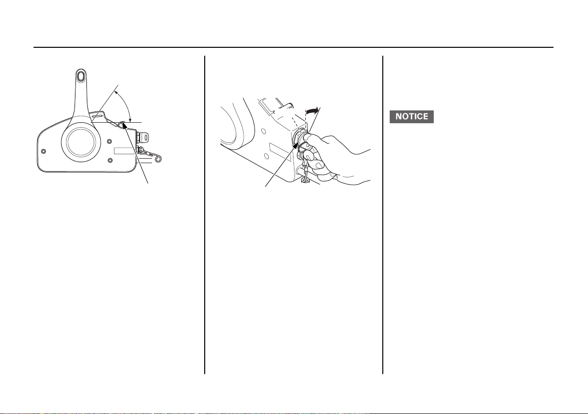
Gearshift/Throttle Control
Lever
The gearshift/throttle control lever
controls engine speed and selects F
(forward), N (neutral), or R (reverse)
gears.
31

CONTROLS AND FEATURES
MAXIMUM
F (FORWARD)
SHIFT
32°
N (NEUTRAL)
R (REVERSE)
GEARSHIFT/THROTTLE
CONTROL LEVER
THROTTLE OPENING
MINIMUM
32°
SHIFT
MINIMUM
THROTTLE OPENING
MAXIMUM
Moving the control lever 32° from N
(neutral) selects the gear, and further
movement increases engine speed.
The control lever automatically locks
itself in the N (neutral) position. To
move the lever out of the N (neutral)
position, you must squeeze the neutral
release lever on the underside of the
lever handle.
A friction adjuster adjusts the
operating resistance of the control
lever(s). Refer to p. 74.
Less friction allows easier control
lever movement. More friction helps
to hold a steady throttle setting while
cruising.
32

CONTROLS AND FEATURES
FAST IDLE LEVER
N (NEUTRAL)
MAXIMUM
FAST IDL E
LOWEST
POSITION
FAST IDLE LEVER
IGNITION SWITCH
OFF
ON
START
Fast Idle Lever
Use the fast idle lever to accelerate
engine warm-up after starting the
engine. Do not use the fast idle lever
when starting the engine.
See page 61 for engine warm-up
instructions.
The fast idle lever allows you to
increase the idle speed only when the
control lever is in the N (neutral)
position. Place the fast idle lever in its
lowest position to cancel the fast idle
and return the control lever to normal
operation.
Flush-Mount Type (Mechanical wire type)
Ignition Switch
The ignition switch controls the
ignition system and the starter motor.
33

CONTROLS AND FEATURES
EMERGENCY
STOP SWITCH
EMERGENCY STOP
SWITCH CLIP
EMERGENCY
STOP SWITCH
LANYARD
EMERGENCY STOP
SWITCH CLIP
EMERGENCY
STOP SWITCH
LANYARD
SPARE SWITCH CLIP
(optional equipment)
Turning the ignition switch key to the
START position starts the engine.
The key automatically returns to the
ON position when released from the
START position.
The engine will not start unless the
gearshift/throttle control lever is in
the N (neutral) position (p. 62) and
the emergency stop switch clip is in
the emergency stop switch.
Turning the ignition switch to the
OFF position stops the engine.
Emergency Stop Switch Clip and Emergency Stop Switch
The emergency stop switch clip must
be inserted in the emergency stop
switch in order for the engine to start
and run. The emergency stop switch
lanyard must be attached securely to
the operator or to the operator’s PFD
(Personal Flotation Device).
When used as described, the
emergency stop switch clip and
emergency stop switch lanyard
system stops the engine if the
operator falls away from the controls.
A spare switch clip (optional
equipment) can be stored in the tool
bag.
34

Gearshift/Throttle Control
GEARSHIFT/THROTTLE CONTROL LEVER
NEUTRAL RELEASE
LEVER
MAXIMUM
F (FORWARD)
SHIFT
35°
N (NEUTRAL)
THROTTLE OPENING
MINIMUM
35°
R (REVERSE)
SHIFT
MINIMUM
THROTTLE OPENING
MAXIMUM
GEARSHIFT/THROTTLE
CONTROL LEVER
Lever
CONTROLS AND FEATURES
The gearshift/throttle control lever
controls engine speed and selects F
(forward), N (neutral), or R (reverse)
gears.
Moving the control lever 35° from N
(neutral) selects the gear, and further
movement increases engine speed.
The control lever automatically locks
itself in the N (neutral) position. To
move the lever out of the N (neutral)
position, you must squeeze the
neutral release lever on the underside
of the lever handle.
A friction adjuster near the base of
the control lever adjusts the operating
resistance of the control lever. Refer
to p. 74.
Less friction allows easier control
lever movement. More friction helps
to hold a steady throttle setting while
cruising.
35

CONTROLS AND FEATURES
FAST IDLE BUTTON
F (FORWARD)
N (NEUTRAL)
R (REVERSE)
NEUTRAL
RELEASE
LEVER
CONTROL
LEVER
Push
FAST IDLE BUTTON
Pull up
Fast Idle Button
Use the fast idle button to accelerate
engine warm-up after starting the
engine. Do not use the fast idle button
when starting the engine.
See page 63 for engine warm-up
instructions.
36
It is necessary to position the control
lever in the N (neutral) position to
push in the fast idle button.
Return the control lever to N (neutral)
position to cancel the fast idle
operation.
The fast idle button allows you to
increase the idle speed without
engaging the drive gears. Move the
control lever forward or reverse after
pushing in the fast idle button to
increase the idle speed.

CONTROLS AND FEATURES
OFF
ON
START
IGNITION SWITCH
EMERGENCY STOP SWITCH
EMERGENCY STOP
SWITCH CLIP
EMERGENCY
STOP SWITCH
LANYARD
EMERGENCY STOP
SWITCH CLIP
EMERGENCY
STOP SWITCH
LANYARD
SPARE SWITCH CLIP
(optional equipment)
Top-Mount Type (Mechanical wire type)
Ignition Switch
The ignition switch controls the
ignition system and the starter motor.
Turning the ignition switch key to the
START position starts the engine. The key
automatically returns to the ON position
when released from the START position.
The engine will not start unless the
gearshift/throttle control lever is in
the N (neutral) position (p. 65) and
the emergency stop switch clip is in
the emergency stop switch.
Emergency Stop Switch Clip and Emergency Stop Switch
The emergency stop switch clip must
be inserted in the emergency stop
switch in order for the engine to start
and run. The emergency stop switch
lanyard must be attached securely to
the operator or to the operator’s PFD
(Personal Flotation Device).
When used as described, the
emergency stop switch clip and
emergency stop switch lanyard
system stops the engine if the
operator falls away from the controls.
A spare switch clip (optional
equipment) can be stored in the tool
bag.
Turning the ignition switch to the
OFF position stops the engine.
37

CONTROLS AND FEATURES
SINGLE TYPE
GEARSHIFT/ THROTTLE CONTROL LEVER
DUAL TYPE
GEARSHIFT/THROTTLE
CONTROL LEVERS
MAXIMUM
SHIFT
F (FORWARD)
35°
N (NEUTRAL)
R (REVERSE)
GEARSHIFT/THROTTLE
CONTROL LEVER
THROTTLE OPENING
MINIMUM
THROTTLE OPENING
MINIMUM
SHIFT
35°
MAXIMUM
Gearshift/Throttle Control
Lever
The gearshift/throttle control lever(s)
controls engine speed and selects F
(forward), N (neutral), or R (reverse)
gears.
38
Moving the control lever 35° from N
(neutral) selects the gear, and further
movement increases engine speed.
A friction adjuster inside the control
box adjusts the operating resistance
of the control lever(s). Refer to p. 74.
Less friction allows easier control
lever movement. More friction helps
to hold a steady throttle setting while
cruising.

CONTROLS AND FEATURES
FAST IDLE BUTTON
F (FORWARD)
N (NEUTRAL)
R (REVERSE)
CONTROL
LEVER
Push
FAST IDLE BUTTON
Fast Idle Button
Use the fast idle button to accelerate
engine warm-up after starting the
engine. Do not use the fast idle button
when starting the engine.
See page 66 for engine warm-up
instructions.
It is necessary to position the control
lever in the N (neutral) position to
push in the fast idle button.
Return the control lever to N (neutral)
position to cancel the fast idle
operation.
The fast idle button allows you to
increase the idle speed without
engaging the drive gears. Move the
control lever forward or reverse after
pushing in the fast idle button to
increase the idle speed.
39

CONTROLS AND FEATURES
(flush-mount type)
CONTROL LEVER
POWER TRIM/TILT SWITCH
(top-mount type
(drive by wire type))
SINGLE TYPE
POWER
TRIM/TILT
SWITCH
CONTROL
LEVER
DUAL TYPE
POWER TRIM/TILT SWITCH
CONTROL LEVERS
POWER
TRIM/TILT
SWITCH
CONTROL
LEVER
(flush-mount type
(mechanical wire type))
POWER TRIM/TILT SWITCH
CONTROL LEVER
(side-mount type)
Common Controls
Power Trim/Tilt Switch
40

(top-mount type
(mechanical wire type))
SINGLE TYPE
POWER TRIM/ TILT SWITCH
CONTROL LEVER
DUAL TYPE
POWER TRIM/TILT SWITCH (Left
and right operations are interlocked)
CONTROL
LEVERS
POWER TRIM/
TILT SWITCH
(Left side
operation only)
POWER TRIM/
TILT SWITCH
(Right side
operation only)
CONTROLS AND FEATURES
You can use the power trim/tilt switch
anytime whether the boat is
underway, stopped, or the ignition
switch is in the OFF position. It is
necessary for the ignition switch to be
in the ON position for the trim meter
to indicate the outboard motor angle.
Trim the outboard motor to obtain the
best performance and stability (p. 75).
Tilt the outboard motor for shallow
water operation, beaching, launching,
or mooring.
For dual mount outboard motors, tilt
them up at the same time.
The power trim/tilt switch is located
on the control lever. It is a rocker
switch with UP and DN (down)
positions for changing the angle of
the outboard motor.
41

CONTROLS AND FEATURES
DUAL TYPE
TRIPLE TYPE
POWER TRIM/TILT SWITCH
POWER TRIM/TILT SWITCH PANEL
㻰㻺
㼁㻼
㻰㻺
㼁㻼
3257 67%'
POWER TILT SWITCH
MANUAL RELIEF VALVE
POWER
(To hold)
MANUAL
(To release)
PTT Switch Panel
3257 67%'&(17(5
㼁㻼
㻰㻺
For multiple outboard motors, the
trim/tilt angle of all outboard motors
is adjusted at the same time by using
the power trim/tilt switch on the
remote control lever and the trim/tilt
angle of each outboard motor is
adjusted by using each power trim/tilt
switch on the panel.
42
Power Tilt Switch
㼁㻼
㻰㻺㼁㻼㻰㻺
The power tilt switch is located on the
engine pan. It is a rocker switch with
UP and DN (down) positions for
changing the angle of the outboard
motor.
Manual Relief Valve
The outboard motor can be tilted
manually after opening the manual
relief valve. This allows the outboard
motor to be tilted up or down when
no battery is connected.
The power tilt switch will operate
without turning the ignition switch
ON.
This switch is used with the engine
stopped to raise the outboard motor
for mooring, trailering, or
maintenance.

CONTROLS AND FEATURES
TILT LOCK LEVER
FREE
LOCK
Front
ENGINE COVER LATCH
Side
ENGINE COVER LATCH (each side)
TIGHTENING
BOLT
TRIM TAB
Tilt Lock Lever
The tilt lock lever is used to support
the outboard motor in the fully-raised
position.
When the boat is to be moored for a
long time, tilt the outboard motor up
as far as it will go. Then move the tilt
lock lever to the LOCK position, and
gently lower the outboard motor until
the lever contacts the stern bracket.
Engine Cover Latches
The engine cover latches fastens the
engine cover to the outboard motor.
Trim Tab
The trim tab compensates for ‘‘torque
steer,’’ which is a reaction of the
outboard motor to propeller rotation.
If uncompensated, torque steer would
make the outboard motor tend to turn
to one side.
When the trim tab is correctly
adjusted (p. 87), steering effort is
equal in either direction.
43

CONTROLS AND FEATURES
TRIM METER
TACHOMETER
NMEA INTERFACE COUPLER
INSTRUMENTS
Trim Meter (standard or optionally applicable equipment)
The trim meter indicates the relative
trim angle of the outboard motor.
Refer to the trim meter when using
the power trim/tilt switch to achieve
the best performance from the boat.
Tachometer (standard or optionally applicable equipment)
The tachometer shows engine speed
in revolutions per minute.
Refer to the tachometer when using
the throttle and power trim/tilt
controls to achieve the best
performance from the boat.
NMEA Interface Coupler
The NMEA2000® interface coupler
can provide information regarding
engine speed, fuel consumption, and
various warnings to an existing
NMEA2000 network via an optional
interface cable. Contact your dealer
for more information.
44

CONTROLS AND FEATURES
Operating Hour Notification System
This outboard motor engine counts
the number of operating hours since
the last periodic maintenance. When
the next periodic maintenance is due,
the engine notifies the NMEA2000
network, and a maintenance
indication is displayed on an
NMEA2000-compatible device.
After periodic maintenance is
performed, reset the hour counter by:
DBW type:
1. Turn ON the power switch or
engine switch. (The buzzer will
sound twice.)
• Wait at least 1 second.
2. With the control lever of the
outboard motor, shift to the "F"
(forward) or "R" (reverse) gear.
3. Turn OFF the power switch or
engine switch.
4. Turn ON the power switch or
engine switch. (The buzzer will
sound twice.)
5. Insert and remove the emergency
stop switch clip five times within
20 seconds.
• When reset, the buzzer will
sound once.
Mechanical wire type:
1. Stop the engine.
2. Set the gearshift at F or R.
3. Turn the ignition switch ON. The
buzzer will sound once.
4. Insert and remove the emergency
stop switch clip five times within
20 seconds.
The buzzer will sound once when
the hour counter is reset.
Periodic maintenance is required
when either the operating hours or the
time since last maintenance reaches
the prescribed limit. Therefore,
periodic maintenance may be
required based on the number of
months since the last maintenance
before the alert based on engine
operating hours displays (see
MAINTENANCE SCHEDULE on
page 85).
Reset the hour counter whenever
maintenance is performed, whether
based on the time interval or the
number of operating hours.
45

CONTROLS AND FEATURES
Every 100 hours
100 hours
after reset
80 hours
after reset
20
hours
Start of
operation
Notify Notify Notify
Maintenance
indication
Maintenance
indication
Maintenance
indication
Maintenance
indication
<Operating hour notification timing>
<Display>
Steps 1 2 3 4
Outboard
motor
Display Switch ON — — —
Maintenance
indication on
display
—
Not shown Shown Shown Not shown
Ignition switch
ON
Start engine Gear at F or R
NMEA2000-compatible display:
• Follow instructions for the display.
• If the display allows selection of
notification to be preset, select
‘‘Notify’’ (or equivalent).
• Turn on the power supply to the
display before turning on the
ignition switch of the outboard
motor.
• The indication may differ,
depending on the type of display.
46

CONTROLS AND FEATURES
(side-mount type)
ACG INDICATOR
(RED)
BUZZER
(flush-mount, top-mount type
(mechanical wire type))
ACG INDICATOR
(RED)
BUZZER
When ‘‘Periodic Maintenance’’ is
indicated:
1. Have the periodic maintenance
performed without delay after
returning to port.
2. Reset the hour counter.
If not reset, the maintenance
indication will remain in the
display, and the hour count until the
next maintenance will be in error.
When the periodic maintenance is
conducted before ‘‘Periodic
Maintenance’’ is indicated, reset the
hour counter.
If not reset, the hour count until the
next maintenance will be in error.
INDICATORS
The indicator lights come on and the
buzzer sounds when you turn the
ignition switch ON, allowing you to
see that they are working. If an
indicator does not light during this
test, it cannot alert you if that system
develops a problem. Have your
Marine dealer check for burned-out
bulbs or other problems. Under
normal conditions, the following
occur when the ignition switch is
turned ON:
1. The ACG, Malfunction, Oil
Pressure, and Overheat indicators
light.
2. The buzzer will beep twice.
3. The Malfunction, Oil Pressure, and
Overheat indicators will go out
after the second beep.
4. The ACG indicator will go out
after the engine starts.
5. The Oil Pressure indicator will
light again after the engine starts
and will stay lit to indicate the oil
pressure is normal.
Alternator (ACG) Indicator
47

CONTROLS AND FEATURES
Display assy
(RED)
ACG INDICATOR
(side-mount type)
MALFUNCTION INDICATOR
(RED)
(flush-mount, top-mount type
(mechanical wire type))
MALFUNCTION
INDICATOR
(RED)
BUZZER
BUZZER
Display assy
(RED)
MALFUNCTION
INDICATOR
Malfunction Indicator
The ACG indicator turns on and the
buzzer sounds in one-second intervals
when the charging system is faulty.
48
When the engine control system
detects an engine control system
malfunction, the malfunction
indicator turns on and the buzzer
sounds at one-second intervals.

CONTROLS AND FEATURES
(side-mount type)
OIL PRESSURE INDICATOR
(GREEN)
OIL PRESSURE
INDICATOR
(GREEN)
BUZZER
BUZZER
(flush-mount, top-mount type
(mechanical wire type))
Display assy
(RED)
OIL PRESSURE
INDICATOR
(side-mount type)
OVERHEAT INDICATOR
(RED)
OVERHEAT
INDICATOR
(RED)
BUZZER
BUZZER
(flush-mount, top-mount type
(mechanical wire type))
Oil Pressure Indicator
Overheat Indicator
When the oil pressure indicator is lit,
oil pressure is OK.
If oil pressure becomes low, the
indicator will go off, and the engine
protection system will limit engine
speed. Refer to TAKING CARE OF
UNEXPECTED PROBLEMS, on
p. 115.
All models are equipped with a
buzzer that sounds continuously
when the oil pressure indicator goes
off.
Low oil pressure indicates that the
engine oil level is low or that there is
a problem with the engine lubrication
system.
49

CONTROLS AND FEATURES
Display assy
(RED)
OVERHEAT
INDICATOR
COOLING SYSTEM INDICATOR
WATER SEPARATOR
When the alert triggers, the overheat
indicator comes on and the buzzer
sounds a steady tone as the engine
speed is reduced to 1,800 rpm. If the
condition persists for another 20
seconds, the engine shuts off. Refer to
TAKING CARE OF
UNEXPECTED PROBLEMS, on
p. 115.
All models are equipped with a
buzzer that sounds continuously
when the red overheat indicator light
comes on.
Engine overheating may be the result
of clogged water intakes.
Cooling System Indicator
Water should flow from the cooling
system indicator while the engine is
running. This shows that water is
circulating through the cooling
system.
If water stops flowing while the
engine is running, it indicates a
cooling system problem, such as
clogged water intakes, which will
cause engine overheating.
OTHER FEATURES
Water Separator Buzzer
The water separator buzzer sounds a
rapid, repeating signal when water
has accumulated in the water
separator.
50

CONTROLS AND FEATURES
ANODE
(each side)
ANODE
(stern bracket)
UP
OUTLET END
(outboard motor side)
PRIMING BULB
INLET END (tank side)
Rev Limiter
The engine is equipped with a rev
limiter to prevent the possibility of
mechanical damage from excessive
engine speed.
The rev limiter may be activated
during operation, limiting engine
speed, if the outboard motor is
trimmed or tilted up excessively, or
when propeller ventilation occurs
during a sharp turn.
If the rev limiter is activated, check
the trim angle of the outboard motor.
Check to see if the correct propeller is
installed.
Anodes
The anodes are made of a sacrificial
material that helps to protect the
outboard motor from corrosion.
There are two anodes on the gear
case, one on the stern bracket and
four small anodes in the water
passages of the engine block.
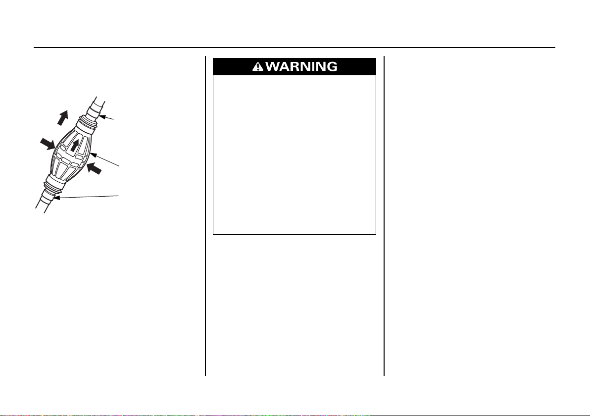
Fuel Priming Bulb
A priming bulb is built into the fuel
hose that connects the fuel tank to the
outboard motor.
Before starting the engine, hold the
priming bulb up in the direction of the
arrow; then squeeze the priming bulb
until it feels firm. This will ensure
that fuel is supplied to the engine
(p. 55).
51

BEFORE OPERATION
ARE YOU READY TO GET UNDERWAY?
Your safety is your responsibility. A
little time spent in preparation will
significantly reduce your risk of
injury.
Knowledge
Read and understand this manual.
Know what the controls do and how
to operate them.
Familiarize yourself with the
outboard motor and its operation
before you get underway. Know what
to do in case of an emergency.
Familiarize yourself with all laws and
regulations relating to boating and the
use of outboard motors.
Safety
Always wear a PFD (Personal
Flotation Device) while on the boat.
Attach the emergency stop switch
lanyard securely to the operator or to
the PFD worn by the operator.
IS YOUR OUTBOARD MOTOR READY TO GO?
For your safety, and to maximize the
service life of your equipment, it is
very important to take a few moments
before you operate the outboard
motor to check its condition.
Be sure to take care of any problem
you find, or have your authorized
Marine dealer correct it, before you
operate the outboard motor.
Failure to properly maintain this
outboard motor, or failing to correct
a problem before operation, could
result in a significant malfunction.
Some malfunctions can cause
serious injuries or death.
Always perform a pre-operation
inspection before each operation
and correct any problems.
(Normal Key without START/
STOP Switch Type)
Before beginning your pre-operation
checks, be sure the IGNITION switch
key is in the OFF position.
(Normal Key with START/
STOP Switch Type)
Before beginning your pre-operation
checks, be sure the power switch is in
the OFF position.
(Honda Smart Key type)
Before beginning your pre-operation
checks, be sure the power switch is in
the power OFF.
52

BEFORE OPERATION
Safety Inspection
• Before each use, look around and
underneath the engine for signs of
oil or gasoline leaks.
• Check that the fuel hose is
undamaged and properly
connected.
• Wipe up any spills before starting
the engine.
• Check the stern bracket to be sure
the outboard motor is securely
installed.
• Check that all controls are
operating properly.
• Replace any damaged parts.
• Check that all fasteners are in place
and securely tightened.
• Check the emergency stop switch
for proper operation. Start the
engine (p. 24, 31, 34 or 37). Make
sure the engine stops by pulling the
emergency stop switch clip from
the emergency stop switch.
Maintenance Inspection
• Check the engine oil level (p. 89).
Running the engine with a low oil
level can cause engine damage.
Overfilling the engine can cause
the engine to smoke or have oil
leaks which can cause engine
damage.
• Check to be sure the propeller is
undamaged and the castle nut is
secured with the cotter pin (p. 105).
• Check that the anodes are securely
attached to the stern bracket and
the gear case (p. 104) and are not
excessively worn. The anodes help
protect the outboard motor from
corrosion.
• Make sure the tool kit is onboard
(p. 84). Replace any missing items.
• Check the fuel level in the fuel tank
(p. 99).
• Check that the battery fluid is
between the upper and lower
levels, and the battery leads are
connected securely.
• Check the fuel filter for water or
sediment accumulated (p. 101).
53

OPERATION
SAFE OPERATING PRECAUTIONS
Exhaust contains poisonous carbon
monoxide gas that can build up to
dangerous levels in closed areas.
Breathing carbon monoxide can
cause unconsciousness or death.
Never run this product's engine in a
closed, or even partly closed area.
To safely realize the full potential of this
outboard motor, you need a complete
understanding of its operation and a certain
amount of practice with its controls.
Before operating the outboard motor for the
first time, please review the
SAFETY INFORMATION
chapter titled
For your safety, do not start or run the
engine in a confined or partly enclosed
area. Your engine’s exhaust contains
poisonous carbon monoxide, a colorless,
odorless gas that can collect rapidly.
Breathing carbon monoxide can cause loss
of consciousness and may lead to death.
BEFORE OPERATION.
IMPORTANT
on page 7 and the
BREAK-IN PROCEDURE
Break-in period: 10 hours
Proper break-in operation allows the
moving parts to wear in smoothly for
best performance and long service
life. Avoid continuous operation at a
steady speed.
First 15 minutes:
Run the engine at trolling speed. Use
the minimum throttle opening
necessary to operate the boat at a safe
trolling speed.
Next 45 minutes:
Run the engine up to a maximum of
2,000 to 3,000 rpm, which is about
10% to 30% of maximum throttle
opening. Operating at maximum
2,000
~3,000 rpm should be limited to
50% of the 45 minutes.
Next 60 minutes:
Run the engine up to a maximum of
4,000 to 5,000 rpm, which is about
50% to 80% of maximum throttle
opening. Operating at maximum
4,000~5,000 rpm should be limited to
50% of the 60 minutes.
30-second full-throttle bursts are OK,
but do not operate the engine
continuously at full throttle.
For boats that plane easily, bring the
boat up on plane, and then reduce the
throttle opening to the recommended
rpm range.
Next 8 hours:
Do not run the engine at full throttle
for more than 5 minutes at a time.
54
OPERATION
UP
OUTLET END
(outboard motor side)
PRIMING BULB
INLET END
(tank side)
FUEL PRIMING
Hold the priming bulb up in the
direction of the arrow; then squeeze
the priming bulb several times until it
feels firm, indicating that fuel has
reached the engine.
Check to be sure there are no fuel
leaks before starting the engine.
Do not touch the priming bulb with
the engine running or when tilting up
the outboard motor. The vapor
separator could overflow.
Gasoline is highly flammable and
explosive.
You can be burned or seriously
injured when handling fuel.
• Stop the engine and let it cool
before handling fuel.
• Keep heat, sparks, and flame
away.
• Handle fuel only outdoors.
• Keep away from your vehicle.
• Wipe up spills immediately.
INFREQUENT OR OCCASIONAL USE
If your outboard motor will be used
on an infrequent or intermittent basis,
please refer to the fuel section of the
STORAGE chapter (p. 109) for
additional information regarding fuel
deterioration.
55

OPERATION
EMERGENCY
STOP SWITCH
EMERGENCY STOP
SWITCH CLIP
EMERGENCY
STOP SWITCH
LANYARD
NEUTRAL
NEUTRAL
REMOTE
CONTROL
LEVER
NEUTRAL
NEUTRAL
REMOTE
CONTROL
LEVER
STARTING THE ENGINE
Control
Flush-Mount Type/
Top-Mount Type (DBW type) ...P. 56
Side-Mount Type ....................... P. 59
Flush-mount type
(Mechanical wire type)..............P. 62
Top-Mount Type
(Mechanical wire type)..............P. 64
Flush-Mount Type/Top-Mount Type (DBW type)
56
1. Put the emergency stop switch clip
in the emergency stop switch, and
attach the emergency stop switch
lanyard securely to the operator or
to the operator’s PFD (Personal
Flotation Device).
The engine will not start or run
unless the emergency stop switch
clip is in the emergency stop
switch.
The emergency stop switch clip
and emergency stop switch lanyard
system is a safety device that will
stop the engine if you fall away
from the controls while operating
the boat.
Always attach the emergency stop
switch lanyard securely to the
operator or to the operator’s PFD
before starting the engine.
Flush-Mount Type (DBW type)
Top-Mount Type (DBW type)
2. Set the control lever in the N
(neutral) position.
The engine will not start if the F
(forward) or R (reverse) gears are
engaged.

OPERATION
IGNITION SWITCH KEY
ON
OFF
START
POWER SWITCH
ON
OFF
START/STOP
SWITCH
POWER SWITCH
ON
(Normal Key without START/
STOP Switch Type)
3. Turn the IGNITION switch key to
the START position and hold it
there until the engine starts.
When the engine starts, release the
key, allowing it to return to the ON
position.
Go to step 5.
• Do not turn the IGNITION
switch key to the START position
while the engine is running.
(Normal Key with START/STOP
Switch Type)
3. Insert the key to the power switch
and turn it to the ON position.
4. Push the start/stop switch.
67$57
6723
(Honda Smart Key Type)
3. Turn the power switch to the right.
The power will not be turned ON
unless the Honda Smart Key is
authenticated.
4. Push the start/stop switch.
When the boat is mounted with the
two outboard motors, push the all
engine start switch.
57

OPERATION
5. Before getting underway, allow the
engine to warm-up sufficiently to
ensure good performance.
Above 41°F (5°C), warm-up the
engine for 2 or 3 minutes.
Below 41°F (5°C), warm-up the
engine for at least 10 minutes at
2,000 rpm. Raise the fast idle lever
to achieve approximately 2,000
rpm.
• If the engine is not properly
warmed up before raising the
engine speed, the buzzer and
overheat indicator may activate
and the engine speed will be
automatically reduced.
• The cooling system may freeze in
areas where the temperature
reaches 32°F (0°C) or below.
Cruising at high speed without
warming the engine up may cause
engine damage.
During the warm-up period, check
the oil pressure indicator (p. 49),
overheat indicator (p. 49), and
cooling system indicator (p. 50).
If the indicators show any
abnormal condition, immediately
stop the engine and determine the
cause of the problem. Refer to
TAKING CARE OF
UNEXPECTED PROBLEMS on
p. 115.
6. If the fast idle lever was used to
warm-up the engine, gradually
lower the lever as the engine
warms up.
58

OPERATION
EMERGENCY
STOP SWITCH
EMERGENCY STOP
SWITCH CLIP
EMERGENCY
STOP SWITCH
LANYARD
N (NEUTRAL)
CONTROL
LEVER
Side-Mount Type
1. Put the emergency stop switch clip
in the emergency stop switch, and
attach the emergency stop switch
lanyard securely to the operator or
to the operator’s PFD (Personal
Flotation Device).
The engine will not start or run
unless the emergency stop switch
clip is in the emergency stop
switch.
The emergency stop switch clip
and emergency stop switch lanyard
system is a safety device that will
stop the engine if you fall away
from the controls while operating
the boat.
Always attach the emergency stop
switch lanyard securely to the
operator or to the operator’s PFD
before starting the engine.
2. Set the control lever in the N
(neutral) position.
The engine will not start if the F
(forward) or R (reverse) gears are
engaged.
59
OPERATION
LOWEST
POSITION
FAST IDLE LEVER
ON
START
IGNITION SWITCH KEY
OFF
3. Leave the fast idle lever in the
OFF (fully lowered) position.
The fast idle lever cannot be raised
unless the control lever is in the N
(neutral) position.
The control lever cannot be moved
away from the N (neutral) position
unless the fast idle lever is lowered.
4. Turn the ignition switch key to the
ON position; the buzzer will sound
twice.
5. Turn the ignition switch key to the
START position and hold it there
until the engine starts.
When the engine starts, release the
key, allowing it to return to the ON
position.
If the engine fails to start within 5
seconds, release the key and wait at
least 10 seconds before operating
the starter again.
• Using the electric starter for more
than 5 seconds at a time will
overheat the starter motor and can
damage it.
• Turning the ignition switch key to
the START position while the
engine is running can damage the
starter motor and flywheel.
60

6. Before getting underway, allow the
MAXIMUM FAST IDLE
FAS T ID LE
RANGE
engine to warm-up sufficiently to
ensure good performance.
• If the engine is not properly
warmed up before raising the
engine speed, the buzzer and
overheat indicator may activate
and the engine speed will be
automatically reduced.
• The cooling system may freeze in
areas where the temperature
reaches 32°F (0°C) or below.
Cruising at high speed without
warming the engine up may cause
engine damage.
OPERATION
During the warm-up period, check
the oil pressure indicator (p. 49),
overheat indicator (p. 49), and
cooling system indicator (p. 50).
If the indicators show any
abnormal condition, immediately
stop the engine and determine the
cause of the problem. Refer to
TAKING CARE OF
UNEXPECTED PROBLEMS on
p. 115.
7. If the fast idle lever was used to
warm-up the engine, gradually
lower the lever as the engine
warms up.
Above 41°F (5°C), warm-up the
engine for 2 or 3 minutes.
Below 41°F (5°C), warm-up the
engine for at least 10 minutes at
2,000 rpm. Raise the fast idle lever
to achieve approximately 2,000
rpm.
When the fast idle lever is fully
lowered, the control lever can be
moved away from the N (neutral)
position.
61

OPERATION
EMERGENCY
STOP SWITCH
EMERGENCY STOP
SWITCH CLIP
EMERGENCY
STOP SWITCH
LANYARD
N (NEUTRAL)
CONTROL
LEVER
Flush-mount type (Mechanical wire type)
1. Put the emergency stop switch clip
in the emergency stop switch, and
attach the emergency stop switch
lanyard securely to the operator or
to the operator’s PFD (Personal
Flotation Device).
The engine will not start or run
unless the emergency stop switch
clip is in the emergency stop
switch.
The emergency stop switch clip
and emergency stop switch lanyard
system is a safety device that will
stop the engine if you fall away
from the controls while operating
the boat.
Always attach the emergency stop
switch lanyard securely to the
operator or to the operator’s PFD
before starting the engine.
2. Set the control lever in the N
(neutral) position.
The engine will not start if the F
(forward) or R (reverse) gears are
engaged.
62

3. Turn the ignition switch key to the
ON
OFF
START
IGNITION
SWITCH
KEY
N (NEUTRAL)
CONTROL
LEVER
FAST IDLE BUTTON
ON position; the buzzer will sound
twice.
4. Turn the ignition switch key to the
START position and hold it there
until the engine starts.
When the engine starts, release the
key, allowing it to return to the ON
position.
If the engine fails to start within 5
seconds, release the key and wait at
least 10 seconds before operating
the starter again.
• Using the electric starter for more
than 5 seconds at a time will
overheat the starter motor and can
damage it.
• Turning the ignition switch key to
the START position while the
engine is running can damage the
starter motor and flywheel.
OPERATION
5. Before getting underway, allow the
engine to warm-up sufficiently to
ensure good performance.
Above 41°F (5°C), warm-up the
engine for 2 or 3 minutes.
Below 41°F (5°C), warm-up the
engine for at least 10 minutes at
2,000 rpm. Push the fast idle
button, and then move the control
lever forward or reverse to open the
throttle and achieve approximately
2,000 rpm.
63

OPERATION
EMERGENCY STOP
SWITCH
EMERGENCY STOP
SWITCH CLIP
EMERGENCY
STOP SWITCH
LANYARD
• If the engine is not properly
warmed up before raising the
engine speed, the buzzer and
overheat indicator may activate
and the engine speed will be
automatically reduced.
• The cooling system may freeze in
areas where the temperature
reaches 32°F (0°C) or below.
Cruising at high speed without
warming the engine up may cause
engine damage.
During the warm-up period, check
the oil pressure indicator (p. 49),
overheat indicator (p. 49), and
cooling system indicator (p. 50).
If the indicators show any
abnormal condition, immediately
stop the engine and determine the
cause of the problem. Refer to
TAKING CARE OF
UNEXPECTED PROBLEMS on
p. 115.
6. If the fast idle control was used to
warm-up the engine, gradually
return the control lever to the N
(neutral) position as the engine
warms up.
Top-Mount Type (Mechanical wire type)
1. Put the emergency stop switch clip
in the emergency stop switch, and
attach the emergency stop switch
lanyard securely to the operator or
to the operator’s PFD (Personal
Flotation Device).
64

The engine will not start or run unless
N (NEUTRAL)
CONTROL
LEVER
IGNITION
SWITCH
KEY
OFF
ON
START
the emergency stop switch clip is in
the emergency stop switch.
The emergency stop switch clip and
emergency stop switch lanyard
system is a safety device that will
stop the engine if you fall away from
the controls while operating the boat.
Always attach the emergency stop
switch lanyard securely to the
operator or to the operator’s PFD
before starting the engine.
2. Set the control lever in the N
(neutral) position.
The engine will not start if the F
(forward) or R (reverse) gears are
engaged.
OPERATION
3. Turn the ignition switch key to the
ON position; the buzzer will sound
twice.
4. Turn the ignition switch key to the
START position and hold it there
until the engine starts.
When the engine starts, release the
key, allowing it to return to the ON
position.
65

OPERATION
N (NEUTRAL)
CONTROL
LEVER
FAST IDLE BUTTON
Push
If the engine fails to start within 5
seconds, release the key and wait at
least 10 seconds before operating
the starter again.
• Using the electric starter for more
than 5 seconds at a time will
overheat the starter motor and can
damage it.
• Turning the ignition switch key to
the START position while the
engine is running can damage the
starter motor and flywheel.
• If the engine is not properly
warmed up before raising the
engine speed, the buzzer and
overheat indicator may activate
and the engine speed will be
automatically reduced.
• The cooling system may freeze in
areas where the temperature
reaches 32°F (0°C) or below.
Cruising at high speed without
warming the engine up may cause
engine damage.
5. Before getting underway, allow the
engine to warm-up sufficiently to
ensure good performance.
66
Above 41°F (5°C), warm-up the
engine for 2 or 3 minutes.
Below 41°F (5°C), warm-up the
engine for at least 10 minutes at
2,000 rpm. Push the fast idle
button, and then move the control
lever forward or reverse to open the
throttle and achieve approximately
2,000 rpm.

OPERATION
ACT INDICATOR
PRESS and HOLD
[-] SWITCH
EMERGENCY
STOP SWITCH
LANYARD
EMERGENCY
STOP SWITCH
CLIP
During the warm-up period, check
the oil pressure indicator (p. 49),
overheat indicator (p. 49), and
cooling system indicator (p. 50).
If the indicators show any
abnormal condition, immediately
stop the engine and determine the
cause of the problem. Refer to
TAKING CARE OF
UNEXPECTED PROBLEMS on
p. 115.
6. If the fast idle control was used to
warm-up the engine, gradually
return the control lever to the N
(neutral) position as the engine
warms up.
Station Select Mode
For multiple station type, use the [-]
switch to change the operating
station.
If you press and hold the [-] switch of
the inactive station when all remote
control lever is in the NEUTRAL
position, you can operate the
outboard motors using this station.
A long buzz sounds once and the
ACT indicator comes on when the
station can be operated.
STOPPING THE ENGINE
Emergency Engine Stopping
Flush-Mount Type, Top-Mount
Type (DBW type)
67

OPERATION
EMERGENCY
STOP SWITCH
EMERGENCY
STOP SWITCH
LANYARD
PULL
EMERGENCY
STOP SWITCH CLIP
Flush-Mount, Top-Mount Type
(Mechanical wire type)
EMERGENCY
STOP SWITCH
CONTROL PANEL
EMERGENCY
STOP SWITCH
LANYARD
PULL
EMERGENCY STOP
SWITCH CLIP
N (NEUTRAL)
N (NEUTRAL)
CONTROL
LEVER
N (NEUTRAL)
CONTROL
LEVER
N (NEUTRAL)
Side-Mount Type
68
To stop the engine in an emergency,
pull the emergency stop switch clip
out of the emergency stop switch by
pulling the emergency stop switch
lanyard.
If the emergency stop switch is
activated while the engine is running,
the engine will shut down abruptly
and the boat will quickly decelerate,
potentially causing occupants and
objects to be thrown forward and/or
overboard.
If the emergency stop switch is
activated, the emergency stop switch
clip must be reinserted before the
engine can be restarted.
We suggest that you stop the engine
this way occasionally to verify that
the engine and emergency stop switch
are operating properly.
Normal Engine Stopping (Flush-Mount Type, Top-Mount Type (DBW type))
Flush-Mount Type
Top-Mount Type (DBW type)

OPERATION
START/STOP
SWITCH
IGNITION SWITCH KEY
OFF
POWER SWITCH
OFF
POWER SWITCH
OFF
1. Move the control lever(s) to the N
(neutral) position.
After cruising at full throttle, cool
down the engine by idling for a few
minutes before stopping the engine.
67$57
6723
(with START/STOP switch)
(without START/STOP switch)
(with START/STOP switch)
2. Push the start/stop switch to stop
the engine.
In the event that the engine does
not stop when the start/stop switch
is pushed, disconnect the fuel line
connector from the outboard motor.
(without START/STOP switch)
2. Turn the ignition switch key to the
OFF position to stop the engine. In
the event that the engine does not
stop when the ignition switch key
is turned to the OFF position, pull
the emergency stop switch clip out
of the emergency stop switch by
pulling the emergency stop switch
lanyard (p. 67).
(Normal Key type)
(Honda Smart Key type)
69

OPERATION
N (NEUTRAL)
CONTROL
LEVER
Flush-Mount Type
(Mechanical wire type)
N (NEUTRAL)
CONTROL
LEVER
(with START/STOP switch)
(Normal Key type)
3. Turn the power switch key to the
OFF position, and then remove and
store it.
(with START/STOP switch)
(Honda Smart Key type)
3. Turn the power switch to the right
or press the lock button on the
Honda Smart Key to turn the power
OFF.
(without START/STOP switch)
3. When the boat is not in use, remove
and store the ignition switch key
and the emergency stop switch clip
and lanyard.
Normal Engine Stopping (Side-Mount Type, Flush-Mount Type, Top-Mount Type (Mechanical wire type))
Side-Mount Type
70

OPERATION
N (NEUTRAL)
CONTROL
LEVER
IGNITION SWITCH KEY
Flush-Mount, Top-Mount Type
(Mechanical wire type)
OFF
IGNITION SWITCH KEY
OFF
Top-Mount Type
(Mechanical wire type)
1. Move the control lever(s) to the N
(neutral) position.
After cruising at full throttle, cool
down the engine by idling for a few
minutes before stopping the engine.
Side-Mount Type
2. Turn the ignition switch key to the
OFF position to stop the engine.
In the event that the engine does
not stop when the ignition switch
key is turned to the OFF position,
pull the emergency stop switch clip
out of the emergency stop switch
by pulling the emergency stop
switch lanyard (p. 67).
3. When the boat is not in use, remove
and store the ignition switch key
and the emergency stop switch clip
and lanyard.
71

OPERATION
N (NEUTRAL)
F (FORWARD)
R (REVERSE)
NEUTRAL
RELEASE
LEVER
CONTROL
LEVER
Top-Mount Type
(DBW type)
N (NEUTRAL)
F (FORWARD)
R (REVERSE)
CONTROL
LEVER
CONTROL LEVER
NEUTRAL
RELEASE LEVER
N (NEUTRAL)
F (FORWARD)
R (REVERSE)
N (NEUTRAL)
F (FORWARD)
R (REVERSE)
NEUTRAL
RELEASE
LEVER
CONTROL
LEVER
Top-Mount Type
(Mechanical wire type)
N (NEUTRAL)
F (FORWARD)
R (REVERSE)
CONTROL
LEVER
GEARSHIFT AND THROTTLE OPERATION
Flush-Mount Type (DBW type)
Side-Mount Type Flush-mount type
(Mechanical wire type)
72

OPERATION
To inc r e ase
friction
Front
side
COVER
Rear
side
To dec r e ase
friction
CONTROL
LEVER
FRICTION
ADJUSTER
BOLT
NUT
To inc re a se
friction
Front
side
COVER
Rear
side
To dec re a se
friction
CONTROL LEVER FRICTION
ADJUSTER BOLT
NUT
To shift gears, move the control lever
to select the F (forward), N (neutral),
or R (reverse) gear.
The control lever cannot be moved
from the N (neutral) position unless
the neutral release lever is squeezed
(flush-mount/side-mount types).
Moving the control lever beyond the
gear selection range increases engine
speed.
Flush-Mount Type (DBW type)
Top-Mount Type (DBW type)
Check whether the control lever moves smoothly.
1. Remove the cover of the control lever.
2. Loosen the nut.
3. Adjust the lever friction when increasing throttle opening and boat speed by
turning the control lever friction adjuster bolt right or left.
4. Tighten the nut to lock the lever friction.
5. Reinstall the cover of the control lever.
73

OPERATION
TO INCREASE
FRICTION
TO DECREASE
FRICTION
CONTROL LEVER
FRICTION ADJUSTER
Flush-mount type
(Mechanical wire type)
CONTROL LEVER
FRICTION ADJUSTER
TO DECREASE
FRICTION
TO INCREASE
FRICTION
PLUG COVER
TO DECREASE
FRICTION
CONTROL LEVER
FRICTION ADJUSTER
SINGLE TYPE
TO INCREASE
FRICTION
PLUG
COVER
TO DECREASE
FRICTION
CONTROL LEVER
FRICTION ADJUSTER
DUAL TYPE
TO INCREASE
FRICTION
Side-Mount Type Top-Mount Type
74
(Mechanical wire type)
Adjust the control lever friction
adjuster so the control lever will hold
a constant throttle setting while
cruising.
STEERING
Steer the boat in the same manner as
an automobile.

OPERATION
CRUISING
Engine Speed
For best fuel economy, limit the
throttle opening to 80%. Use the
throttle friction control (p. 73) to help
you hold a steady speed.
For rough water conditions or large
waves, slow down to prevent the
propeller from rising out of the water.
The engine is equipped with a rev
limiter to prevent the possibility of
mechanical damage from excessive
engine speed.
If, for example, the outboard motor is
tilted excessively or propeller
ventilation occurs during a sharp turn,
the engine may overrev, activating
the rev limiter.
If engine speed becomes unstable at
high speed due to activation of the rev
limiter, reduce speed and check the
trim angle of the outboard motor.
Trim
Use the power trim/tilt switch to trim
the outboard motor for the best
performance and stability.
You can use the power trim/tilt switch
at any time, whether the boat is
underway or stopped.
Press the UP or DN (down) side of
the switch to adjust the angle of the
outboard motor.
Refer to the trim meter (p. 44) for an
indication of whether the outboard
motor is trimmed high or low.
It is necessary to trim the angle of the
outboard motor to compensate for
changes in boat load, weight
distribution, water conditions, or
propeller selection.
Under normal conditions, the boat
will perform best when the
antiventilation plate is level with the
water surface.
When cruising into a high wind, trim
the outboard motor down slightly to
level the boat and improve stability.
With a tail wind, trim the outboard
motor up slightly.
Excessive trim/tilt angle during
operation can cause propeller
ventilation, overheating, and water
pump damage.
75

OPERATION
POWER
TRIM/TILT
SWITCH
POWER
TRIM/TILT
SWITCH
POWER
TRIM/TILT
SWITCH
POWER TRIM/TILT SWITCH
Flush-mount type
(Mechanical wire type)
POWER TRIM/TILT SWITCH
POWER TRIM/ TILT SWITCH
Dual Top-Mount Type
(Mechanical wire type)
POWER TRIM/TILT SWITCH
(LEFT) (RIGHT)
SINGLE TYPE
DUAL TYPE
Flush-Mount Type (DBW type)
Single Top-Mount Type (DBW type)
Dual Top-Mount Type (DBW type)
Side-Mount Type Single Top-Mount Type
(Mechanical wire type)
76

OPERATION
POWER TRIM/TILT SWITCH
DUAL TYPE
Press UP to
raise bow
Press DN to
lower bow.
POWER TRIM/TILT SWITCH
TRIPLE TYPE
Press UP to
raise bow
Press DN to
lower bow.
OUTBOARD
MOTOR
TRIMMED TOO
LOW
OUTBOARD
MOTOR
TRIMMED TOO
HIGH
OUTBOARD MOTOR
TRIMMED CORRECTLY
BOW TOO LOW DUE TO
1. LOAD IN THE FRONT
2. OUTBOARD MOTOR TRIMMED
TOO LOW
BOW TOO HIGH DUE TO
1. LOAD IN THE REAR
2. OUTBOARD MOTOR TRIMMED
TOO HIGH
TRIM TAB BOLT
TRIM TAB
PTT Switch Panel
For multiple outboard motors, the
trim/tilt angle of all outboard motors
is adjusted at the same time by using
the power trim/tilt switch on the
remote control lever and the trim/tilt
angle of each outboard motor is
adjusted by using each power trim/tilt
switch on the panel.
3257 67%'
㼁㻼
㻰㻺
3257 67%'&(17(5
㼁㻼
㼁㻼
㻰㻺
If steering effort is not equal in both
directions, adjust the trim tab to
compensate for ‘‘torque steer,’’ which
is the reaction of the outboard motor
㼁㻼
㻰㻺
㻰㻺㼁㻼㻰㻺
to propeller rotation.
Adjust the trim tab with the engine
stopped. Loosen the bolt above the
trim tab, turn the trim tab, and then
tighten the bolt securely.
When the trim tab is correctly
adjusted, steering effort will be equal
in both directions.
Refer to TRIM TAB ADJUSTMENT
on p. 87.
77
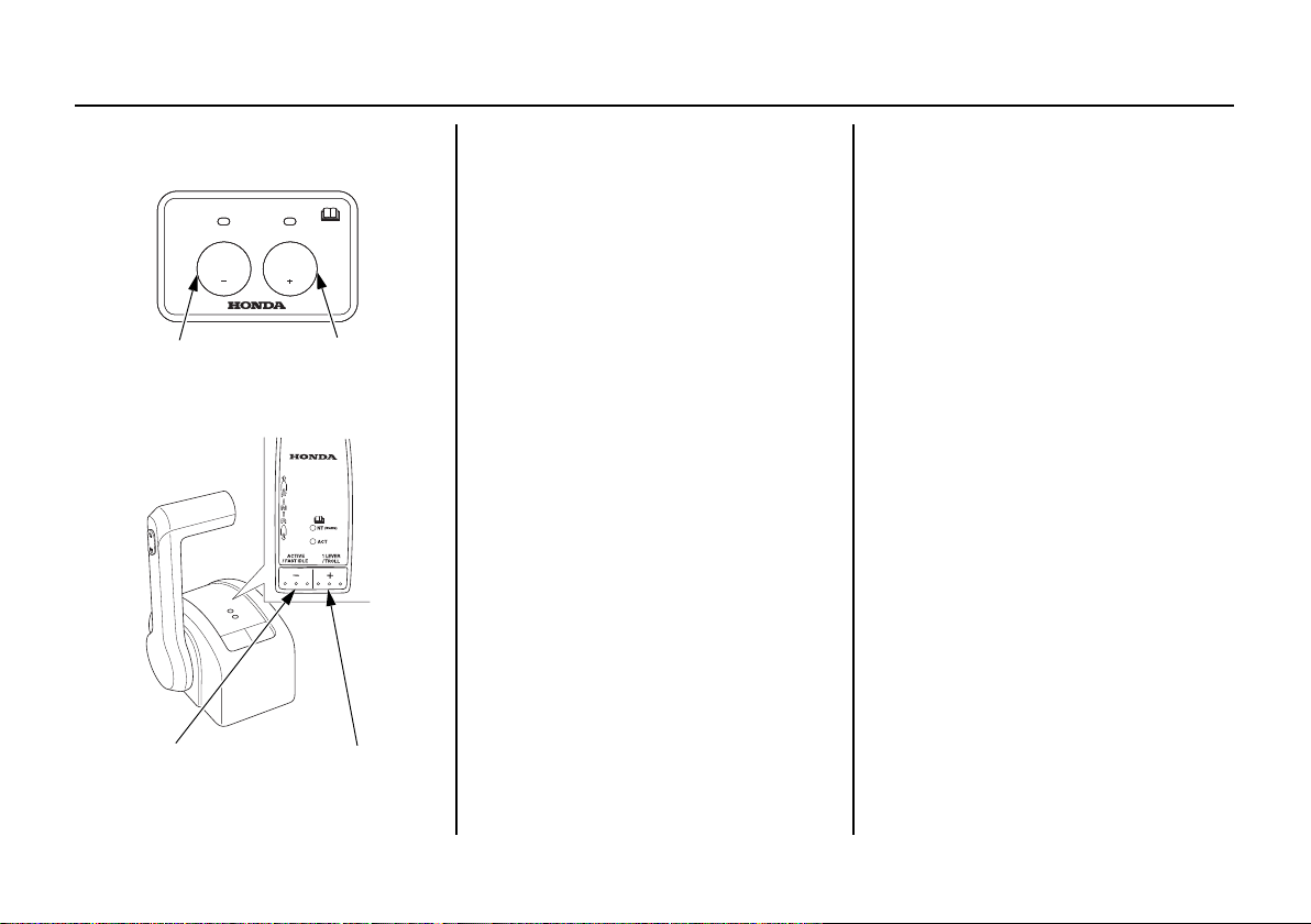
OPERATION
[-] SWITCH [+] SWITCH
(FLUSH-MOUNT type)
[-] SWITCH [+] SWITCH
(Top-Mount Type (DBW type))
TROLLING MODE [-] Switch: Reduce engine speed
[+] Switch: Increase engine speed
:$50
17
)$67,'/(
752// 752//752// 752//752//
$&7
752//
After the engine has warmed up,
keeping [+] switch pushed when
cruising with the throttle fully closed,
changes the mode to trolling mode.
A long buzz sounds once.
When the mode is changed to trolling
mode, the engine speed is 650 min
-1
(rpm).
You can adjust the engine speed by
-1
50 min
(rpm) every time you press
the switch once. You will hear a short
buzz.
The engine speed can be adjusted
within the range of 650 – 1,000 min
-1
(rpm).
Continuing to press the switch will
not decrease or increase the engine
-1
speed beyond the lower (650 min
(rpm)) or higher (1,000 min
-1
(rpm))
limit.
If you try to do this, a short buzz
sounds twice.
The throttle may be operated while in
trolling mode. The trolling mode is
cancelled when you reach 3,000 min
-1
(rpm).
78

OPERATION
[+] SWITCH
SYNC
INDICATOR
ONE-LEVER MODE
(For multiple outboard motors
type)
Shifting gear and the engine speed
adjustment of the all outboard motors
can be performed with one remote
control lever when in one-lever
mode.
If you press and hold the [+] switch
when all remote control lever is in the
NEUTRAL position, the mode
changes to one-lever mode.
A long buzz sounds once and SYNC
indicator comes on.
SHALLOW WATER OPERATION
When operating in shallow water, use
the power trim/tilt switch (p. 75 – 76)
to tilt the outboard motor so that the
propeller and gear case won’t hit the
bottom.
Proceed at low speed, and monitor
water flow from the cooling system
indicator (p. 50) to be sure the
outboard motor is not tilted so high
that the water intakes are out of the
water.
An excessive trim/tilt angle during
operation can cause propeller
ventilation, overheating, and water
pump damage. This type of damage is
not covered by the Distributor’s
Limited Warranty (U.S.) /
Distributor’s Warranty (CA.) (p. 145).
79

OPERATION
TRIM RODS
POWER TILT SWITCH
TILT LOCK LEVER
(Lock position)
STERN BRACKET
FREE
LOCK
MOORING, BEACHING, LAUNCHING
Before tilting up, leave the outboard
motor in the running position for one
minute after stopping the engine to
drain the water from inside the
engine.
Stop the engine and disconnect the
fuel hose from the outboard motor
before tilting the outboard motor.
To raise the outboard motor out of the
water while the engine is stopped and
the boat is moored, or for maximum
clearance when beaching or
launching, use the power tilt switch
on the engine pan to tilt the outboard
motor up as far as it will go.
Move the tilt lock lever to the LOCK
position, and then gently lower the
outboard motor until the lever
contacts the stern bracket. Use the
power tilt switch to fully shorten the
trim rods.
80
If more clearance is needed to swing
the tilt lock lever into the LOCK
position, rock the outboard motor
forward slightly by pulling on the
engine cover grip.
To lower the outboard motor, tilt up,
move the tilt lock lever to the FREE
position, and then lower the outboard
motor to the desired position.

OPERATION
MANUAL RELIEF VALVE
POWER
(To hold)
MANUAL
(To release)
Do not attempt to use the power tilt
switch to tilt the outboard motor
down while the tilt lock lever is in the
LOCK position. Damage to the power
tilt system may occur.
The outboard motor can also be tilted
manually after opening the manual
relief valve. This feature enables the
outboard motor to be tilted up or
down when no battery is connected.
For manual tilting, use a screwdriver
to turn the valve counterclockwise 1
or 2 turns. Close the valve firmly
after positioning the engine.
Be sure the valve is closed before
operating the outboard motor. If the
valve is not closed, the outboard
motor will tilt up when operated in
reverse.
Check that nobody is under the
outboard motor before opening the
manual relief valve. If the manual
relief valve is loosened (turned
counterclockwise) when the outboard
motor is tilted up, the outboard motor
will suddenly tilt down.
MULTIPLE OUTBOARD MOTORS
On boats equipped with more than
one outboard motor, all motors
normally operate at the same time.
If one or more motor(s) is stopped
while the other(s) is running, put the
stopped motor in ‘‘N’’ (neutral) and
tilt it up so its propeller is above the
water’s surface.
If the propeller of the stopped motor
is left in the water, it may turn as the
boat moves through the water,
causing a reverse flow of water from
the exhaust side. This reverse flow
will happen if the stopped engine’s
propeller is in the water, its gearshift
is in ‘‘R’’ (reverse), and the boat is
moving forward. Reverse flow can
cause an engine malfunction.
81

SERVICING YOUR OUTBOARD MOTOR
THE IMPORTANCE OF MAINTENANCE
Proper maintenance is essential for
safe, economical, and trouble-free
operation. It will also help reduce air
pollution.
Failure to properly maintain this
outboard motor, or failing to
correct a problem before
operation, could result in a
significant malfunction.
Some malfunctions can cause
serious injuries or death.
Always follow the inspection and
maintenance recommendations
and schedules in this owner’s
manual.
To help you properly care for your
outboard motor, the following pages
include a maintenance schedule,
routine inspection procedures, and
simple maintenance procedures using
basic hand tools. Other service tasks
that are more difficult or require
special tools are best handled by
professionals and are normally
performed by a Honda technician or
other qualified mechanic.
The maintenance schedule applies to
normal operating conditions. If you
operate your outboard motor under
unusual conditions, consult an
authorized Honda Marine dealer for
recommendations applicable to your
individual needs and use.
Remember that your authorized
Honda Marine dealer knows your
outboard motor best and is fully
equipped to maintain and repair it.
To ensure the best quality and
reliability, use only new, Honda
Genuine parts or their equivalents for
repair and replacement.
Maintenance, replacement, or
repair of the emission control
devices and systems may be
performed by any marine engine
repair establishment or individual,
using parts that are ‘‘certified’’ to
EPA standards.
82

SERVICING YOUR OUTBOARD MOTOR
MAINTENANCE SAFETY
Some of the most important safety
precautions follow. However, we
cannot warn you of every conceivable
hazard that can arise in performing
maintenance. Only you can decide
whether or not you should perform a
given task.
Improper maintenance can cause
an unsafe condition.
Failure to properly follow
maintenance instructions and
precautions can cause serious
injuries or death.
Always follow the procedures
and precautions in this owner’s
manual.
Safety Precautions
• Make sure the engine is off before
you begin any maintenance or
repairs. This will eliminate several
potential hazards:
─ Carbon monoxide poisoning
from engine exhaust.
Do not start or run the engine in
a confined or partly enclosed
area.
─ Burns from hot parts.
Let the engine and exhaust
system cool before touching.
─ Injury from moving parts.
Do not run the engine unless
instructed to do so.
• Read the instructions before you
begin, and make sure you have the
tools and skills required.
• To reduce the possibility of fire or
explosion, be careful when
working around gasoline. Use only
a nonflammable solvent, not
gasoline, to clean parts. Keep
cigarettes, sparks, and flames away
from all fuel-related parts.
• Wear gloves when handling the
propeller to protect your hands
from sharp edges.
83

SERVICING YOUR OUTBOARD MOTOR
10 mm BOX WRENCH
PHILLIPS SCREWDRIVER
19 mm EYE WRENCH
GRIP SPARK PLUG WRENCH
6 mm HEX. WRENCH
TOOL BAG
OWNER’S MANUAL
TOOL KIT and OWNER’S MANUAL
(Tool kit does not come with Counter Rotation Types)
The tool kit can be used for simple maintenance procedures and emergency
repairs. Keep these items on the boat so that they will always be available if you
need them.
SPARE EMERGENCY STOP SWITCH CLIP (applicable types)
Always carry a spare emergency stop
switch clip onboard. The spare clip
may either be stored in the tool bag or
in an easily accessible location on the
boat.
If your tool kit needs replacement, it is not available as a kit and each item must
be ordered individually.
84

SERVICING YOUR OUTBOARD MOTOR
REGULAR SERVICE PERIOD (3)
Perform at every indicated month or operating
hour interval, whichever comes first.
ITEM
MAINTENANCE SCHEDULE
Follow the MAINTENANCE SCHEDULE table and service your outboard motor accordingly. Please note, a claim for
warranty coverage will not be denied simply because the maintenance schedule for your outboard motor was not
followed. However, any part(s) that fails specifically due to lack of maintenance, or improperly performed maintenance,
would not be covered under the Distributor’s Limited Warranty (U.S.) / Distributor’s Warranty (CA.).
Every
3 years
or
or
600 hrs.
1,200 hrs.
Engine oil Check level o
Engine oil filter Replace o (2)
Gear case oil Change o (2) o (2)
Timing belt Check-adjust o (2)
ACG belt Check-adjust o (2)
Throttle linkage and Control Cable (9) Check-adjust o (2) o (2)
Valve clearance Check-adjust o (2)
Spark plug (nickel) Check-adjust/Replace o
Spark plug (iridium) (Optional part) Check o
Propeller and Cotter pin Check o o
Anode metal (Outside engine) (6) Check o o
Anode metal (Inside engine) Sleeve Check o (2)
(6) Exhaust manifold Check o (2)
V bank bottom Replace o (2)
Idling speed Check-adjust o (2) o (2)
Lubrication Grease o (1) o (1)
Note:
(1) Lubricate more frequently when used in salt water.
(2) These items should be serviced by your servicing dealer, unless you have the proper tools and are mechanically proficient.
Refer to the Honda Shop Manual for service procedures. See “Honda Publications” on page 142 for ordering information.
(3) For professional commercial use, log hours of operation to determine proper maintenance intervals.
(6) Replace the anodes when they have been reduced to about two-thirds of their original size, or if they are crumling.
(9) Mechanical Remote Control type only.
(Optional part) Replace o
First
Each use After use
Change o o
month
or
20 hrs.
Every
6 months
100 hrs.
Every
year
or
200 hrs.
Every
2 years
or
400 hrs.
Every
6 years
or
85

SERVICING YOUR OUTBOARD MOTOR
REGULAR SERVICE PERIOD (3)
Perform at every indicated month or operating
hour interval, whichever comes first.
ITEM
Fuel filter with water separator
(Low pressure side)
Fuel filter
(High pressure side)
Thermostat and thermostat cover Check/Replace o (2)
Fuel line Check o (7)
Battery and cable connection Check level-tightness o
Bolts and Nuts Check-tightness o (2) o (2)
Crankcase breather tube Check o (2)
Cooling water passages Clean o (4) o (4)
Coolant leak Check o
Water pump and Woodruff Key Check o (2)
Housing, Impeller Check o (2)
Emergency stop switch Check o
Engine oil leak Check o
Each operation part Check o
Engine condition (5) Check o
Power Trim/Tilt Check o (2)
Shift Cable (9) Check-adjust o (2)
Note:
(2) These items should be serviced by your servicing dealer, unless you have the proper tools and are mechanically proficient.
Refer to the Honda Shop Manual for service procedures. See “Honda Publications” on page 142 for ordering information.
(3) For professional commercial use, log hours of operation to determine proper maintenance intervals.
(4) When operating in salt water, turbid or muddy water, the engine should be flushed with clean water after each use.
(5) Upon starting, check for unusual engine sounds and cooling water flowing freely from the check hole.
(7) Check the fuel line for leaks, cracks, or damage. If it is leaking, cracked, or damaged, take it to your servicing dealer for replacement before using your
outboard.
(8) Replace the fuel line if there are signs of leaks, cracks, or damage.
(9) Mechanical Remote Control type only.
86
First
Each use After use
Check o o
Replace o
Replace
Replace Every 2 years (If necessary) (2) (8)
month
20 hrs.
Every
6 months
or
100 hrs.
Every
year
or
200 hrs.
Every
2 years
or
400 hrs.
o (2)
Every
3 years
or
600 hrs.
Every
6 years
or
or
1,200 hrs.

TRIM TAB ADJUSTMENT
TRIM TAB BOLT
TRIM TAB
LEFT
TRIM TAB BOLT
TRIM TAB
RIGHT
The trim tab compensates for ‘‘torque
steer,’’ which is a reaction of the
outboard motor to propeller rotation.
If uncompensated, torque steer would
make the outboard motor tend to turn
to one side.
When the trim tab is correctly
adjusted, steering effort is equal in
either direction.
If steering effort is unequal, loosen
the trim tab bolt and adjust the angle
of the trim tab. Retighten the trim tab
bolt securely.
SERVICING YOUR OUTBOARD MOTOR
If less effort is required to make left
turns, move the back of the trim tab
left.
If less effort is required to make right
turns, move the back of the trim tab
right.
Adjust the trim tab in small
increments, and retest steering effort
with the boat evenly loaded and
running at cruising speed.
87

SERVICING YOUR OUTBOARD MOTOR
MANUAL RELIEF VALVE
POWER
(To hold)
MANUAL
(To release)
Front
ENGINE COVER LATCH
Side
ENGINE COVER LATCH (each side)
COVER SIDE
COVER LOCKS
MAIN BODY SIDE
Side
Front
ENGINE COVER LATCH
MANUAL RELIEF VALVE
The outboard motor can be tilted
manually after opening the manual
relief valve. This feature enables the
outboard motor to be tilted up or
down when no battery is connected.
For manual tilting, use a screwdriver
to turn the valve counterclockwise 1
or 2 turns. Close the valve firmly
after positioning the outboard motor.
Be sure the valve is closed before
operating the outboard motor. If the
valve is not closed, the outboard
motor will tilt up when operated in
reverse.
88
ENGINE COVER REMOVAL AND INSTALLATION
Removal
1. Pull all the engine cover latches.
2. Remove the engine cover by lifting it
straight up from the outboard motor.
Installation
1. Place the engine cover on the main body.
2. Slide the engine cover so that the
cover lock on the cover aligns with
the lock in the main body.

Side
ENGINE COVER LATCH (each side)
OIL LEVEL DIPSTICK
UPPER
LIMIT
LOWER
LIMIT
OIL FILLER CAP
3. Push the engine cover until any gap
between the engine cover and main
body is eliminated.
4. Push all the engine cover latches to
lock them.
Lubricate the engine cover rubber
sealing ring with silicone spray to
make installation easier.
The cover should be tight at the
mid-case point. If the cover is loose
or difficult to secure, an adjustment
may be necessary. Please see the shop
manual or your Marine dealer for
adjustment.
SERVICING YOUR OUTBOARD MOTOR
Engine Oil Level Check
Check the engine oil level with the
engine stopped and the outboard
motor in the vertical position.
1. Unlock and remove the engine
cover (p. 88).
2. Remove the dipstick and wipe it
clean.
3. Insert the dipstick all the way in,
then remove it and check the oil
level shown on the dipstick.
4. If the oil level is low, remove the
oil filler cap, and add oil to reach
the upper limit mark shown on the
dipstick. Use the oil recommended
on p. 93.
• Running the engine with a low
oil level can cause engine
damage.
• Do not overfill. Overfilling the
engine will cause it to smoke or
have oil leaks.
89

SERVICING YOUR OUTBOARD MOTOR
5. Insert the dipstick all the way in.
Install the oil filler cap and tighten
it securely. Do not overtighten.
6. Install and lock the engine cover
(p. 88).
When you check the oil level with the dipstick, you might notice the engine oil
appears milky or the oil level has increased. If you notice either condition,
change the engine oil. See the following table for an explanation of these
conditions.
Operating Method Result Effect
Running the engine below
3,000 rpm for more than 30%
of the time so the engine does
not warm up.
Frequent starting and stopping
without allowing the engine to
warm up.
• Water condenses in the
engine and mixes with the oil,
resulting in a milky
appearance.
• Unburned fuel mixes with the
oil, increasing the volume of
oil.
The engine oil deteriorates,
becomes less efficient as a
lubricant, and causes an
engine malfunction.
90

SERVICING YOUR OUTBOARD MOTOR
SEALING WASHER
(Replace)
OIL DRAIN
GUIDE
DRAIN BOLT
Engine Oil Change
An engine oil evacuation/filling
device may be used to remove/add
the engine oil.
Drain the used oil while the engine is
warm. Warm oil drains quickly and
completely.
1. Unlock and remove the engine
cover (p. 88).
2. Place a suitable container below the
oil drain guide to catch the used oil,
and then remove the oil filler cap,
drain bolt, and sealing washer.
3. Allow the used oil to drain
completely. Use a new sealing
washer, and then reinstall the
engine oil drain bolt and washer.
Tighten the drain bolt securely.
TIGHTENING TORQUE:
17 lbf·ft (23 N·m, 2.3 kgf·m)
Improper disposal of engine oil can
be harmful to the environment.
If you change your own oil, please
dispose of the used oil properly.
Put it in a sealed container, and
take it to a recycling center. Do not
throw it in the trash, pour it on the
ground or down a drain.
4. Install the drain bolt cover and
secure it with the screw.
5. With the outboard motor in a
vertical position, fill to the upper
limit mark on the dipstick (p. 89)
with the recommended oil.
Engine oil refill capacity:
Without oil filter change:
8.0 US qt (7.6 L)
With oil filter change:
8.2 US qt (7.8 L)
6. Install the oil filler cap and tighten
it securely.
91

SERVICING YOUR OUTBOARD MOTOR
USE A SUITABLE TOOL
OIL FILTER
OIL DRAIN GUIDE
RUBBER SEAL
7. Install and lock the engine cover
(p. 88).
Oil Filter Change
1. Drain the engine oil, and reinstall
the drain bolt, washer, and drain
bolt cover (see Engine Oil Change
on p. 91).
2. Tilt the outboard motor, and place a
suitable container below the oil
drain guide to catch the used oil.
3. Use a suitable tool to remove the
oil filter, and thoroughly drain the
filter into the used oil container.
4. Clean the oil filter mounting base,
and coat the rubber seal of the new
oil filter with clean engine oil.
Use only a Honda Genuine oil
filter or a filter of equivalent
quality specified for your model.
Using the wrong filter, or a
non-Honda filter which is not of
equivalent quality, may cause
engine damage.
5. Screw on the new filter by hand
until it contacts the engine, then use
a suitable tool to tighten the filter
an additional 7/8 turn.
TIGHTENING TORQUE:
9 lbf·ft (12 N·m, 1.2 kgf·m)
92

SERVICING YOUR OUTBOARD MOTOR
AMBIENT TEMPERATURE
6. Return the outboard motor to the
vertical position, and fill the
crankcase with the specified
amount (p. 91) of the
recommended oil.
Do not overfill. Overfilling the
engine will cause it to smoke or
have oil leaks.
7. Start the engine and check for leaks.
Running the engine without water
can cause serious engine damage.
If you are changing the oil filter
while the outboard motor is out of
the water, use commercially
available earmuffs and a hose to
supply water.
8. Stop the engine, and check the oil
level as described on page 89. If
necessary, add oil to bring the oil
level to the upper limit mark on the
dipstick.
Engine Oil Recommendations
Oil is a major factor affecting
performance and service life. Use
4-stroke detergent oil.
®
Honda 10W-30 FC-W
motor oil is recommended for general
use.
®
FC-W
is a registered trademark of
the National Marine Manufacturers
Association.
outboard
If Honda 10W-30 FC-W oil is not
available, Honda recommends that
you use API service category SG,
SH, SJ or SL oil. The SAE oil
viscosity and service category are in
the API label on the oil container.
93
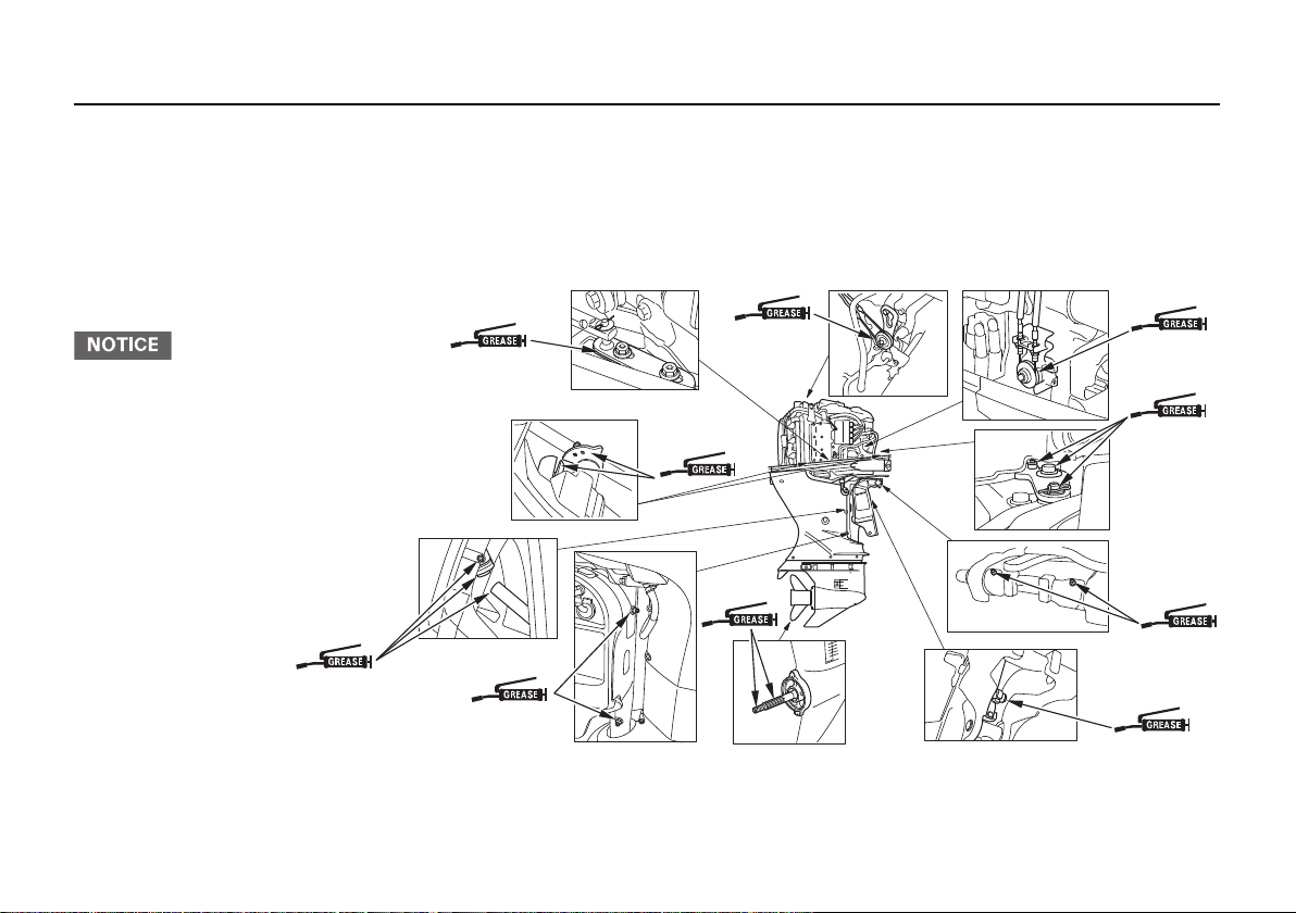
SERVICING YOUR OUTBOARD MOTOR
PTT THRUST
RECEIVER
(each side)
SWIVEL
PROPELLER
SHAFT
TILT LOCK LEVER/
SHAFT CAM
SHIFT ARM/
CLICK
ROLLER/
NEUTRAL
SWITCH
TILT SHAFT
THROTTLE ARM/
SHIFT ARM SHAFT
(flush-mount type,
top-mount type
(mechanical wire
type))
THROTTLE REEL
(flush-mount type,
top-mount type
(mechanical wire
type))
ENGINE
COVER
LATCH/LOCK
(each side)
SHIFT LINK
PIVOT/SHIFT
LINK GUIDE
(DBW type)
Lubrication Points
Apply Honda Marine waterproof grease to the parts
shown below:
Lubrication interval:
After the first 20 hours or 1 month, then every 100
hours or 6 months (refer to the MAINTENANCE
SCHEDULE on page 85).
Apply anticorrosion oil to pivot
surfaces where grease cannot
penetrate.
Apply corrosion inhibitor to all areas under the engine cover and any exposed metal surfaces except the belts.
94

SERVICING YOUR OUTBOARD MOTOR
WIRE CONNECTOR
BOLT
IGNITION COIL GUARD
IGNITION COIL
Spark Plug Service
<Standard Spark Plug>
RECOMMENDED SPARK PLUGS:
ZFR6K-11E (NGK)
Incorrect spark plugs can cause
engine damage.
See page 98 for instructions of
handling the Iridium spark plugs
(optional parts).
1. Disconnect the battery negative (–)
terminal.
2. Unlock and remove the engine
cover (p. 88).
3. Disconnect the wire connector
from the ignition coil by pushing
on the lock tab and pulling on the
connector. Pull on the plastic
connector, not the wires.
4. Use a 10 mm wrench to remove all
three bolts holding the ignition
coils, and then remove the ignition
coil guard. Remove the ignition
coil by pulling it up slightly.
Do not strike or drop the ignition coil,
or it may be damaged and require
replacement.
95

SERVICING YOUR OUTBOARD MOTOR
SPARK PLUG WRENCH
19 mm EYE
WRENCH
New plug Plug needing
replacement
SIDE ELECTRODE
SEALING
WA S HE R
INSULATOR
0.039 – 0.043 in
(1.0 – 1.1 mm)
5. Remove the spark plugs with a
spark plug wrench and 19 mm eye
wrench.
96
6. Inspect the spark plugs. Replace
them if the electrodes are worn, or
if the insulators are cracked or
chipped.
7. Measure the spark plug electrode
gap with a wire-type feeler gauge.
Correct the gap, if necessary, by
carefully bending the side
electrode.
The gap should be:
0.039 – 0.043 in (1.0 – 1.1 mm)
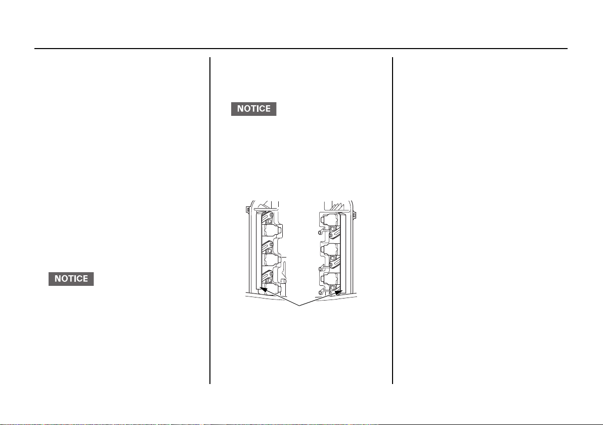
SERVICING YOUR OUTBOARD MOTOR
Left side
IGNITION COIL GUARD
Right side
8. Install the spark plugs carefully, by
hand, to avoid cross-threading.
9. After each spark plug seats, tighten
with the spark plug wrench
supplied in the tool kit to compress
the sealing washer.
If reinstalling used spark plugs,
tighten 1/8 – 1/4 turn after the
spark plugs seat.
If installing new spark plugs,
tighten 1/2 turn after the spark
plugs seat.
TIGHTENING TORQUE:
13 lbf·ft (18 N·m, 1.8 kgf·m)
Loose spark plugs can overheat
and damage the engine.
Overtightening the spark plugs
can damage the threads in the
cylinder head.
10. Install the ignition coil and the
ignition coil guard. Reinstall the
bolts.
Check the left and right side of the
ignition coil guard before
installing them. If you install the
wrong side, the ignition coil may
be damaged.
11. Push the wire connector onto the
ignition coil. Make sure it locks in
place.
12. Repeat this procedure for the
other five spark plugs.
13. Reinstall the engine cover.
97

SERVICING YOUR OUTBOARD MOTOR
<Optional Parts: Iridium Spark
Plug>
RECOMMENDED SPARK PLUGS:
IZFR6K-11E (NGK)
Incorrect spark plugs can cause
engine damage.
Installation and removal procedure of
the Iridium spark plugs are the same
as the standard spark plugs.
These spark plugs have an iridium
coated center electrode.
Be sure to observe the following
when servicing iridium spark plugs.
• Do not clean the spark plugs. If an
electrode is contaminated with
accumulated objects or dirt, replace
the spark plug with a new one.
• Use only a ‘‘wire-type feeler
gauge’’ to check the spark plug gap
if necessary. To prevent damaging
the iridium coating of the center
electrode, never use a ‘‘leaf-type
feeler gauge.’’
The gap should be 0.039 – 0.043
inches (1.0 – 1.1 mm).
• Do not adjust the spark plug gap.
If the gap is out of specification,
replace the spark plug with a new
one.
98
 Loading...