

Page 1
T
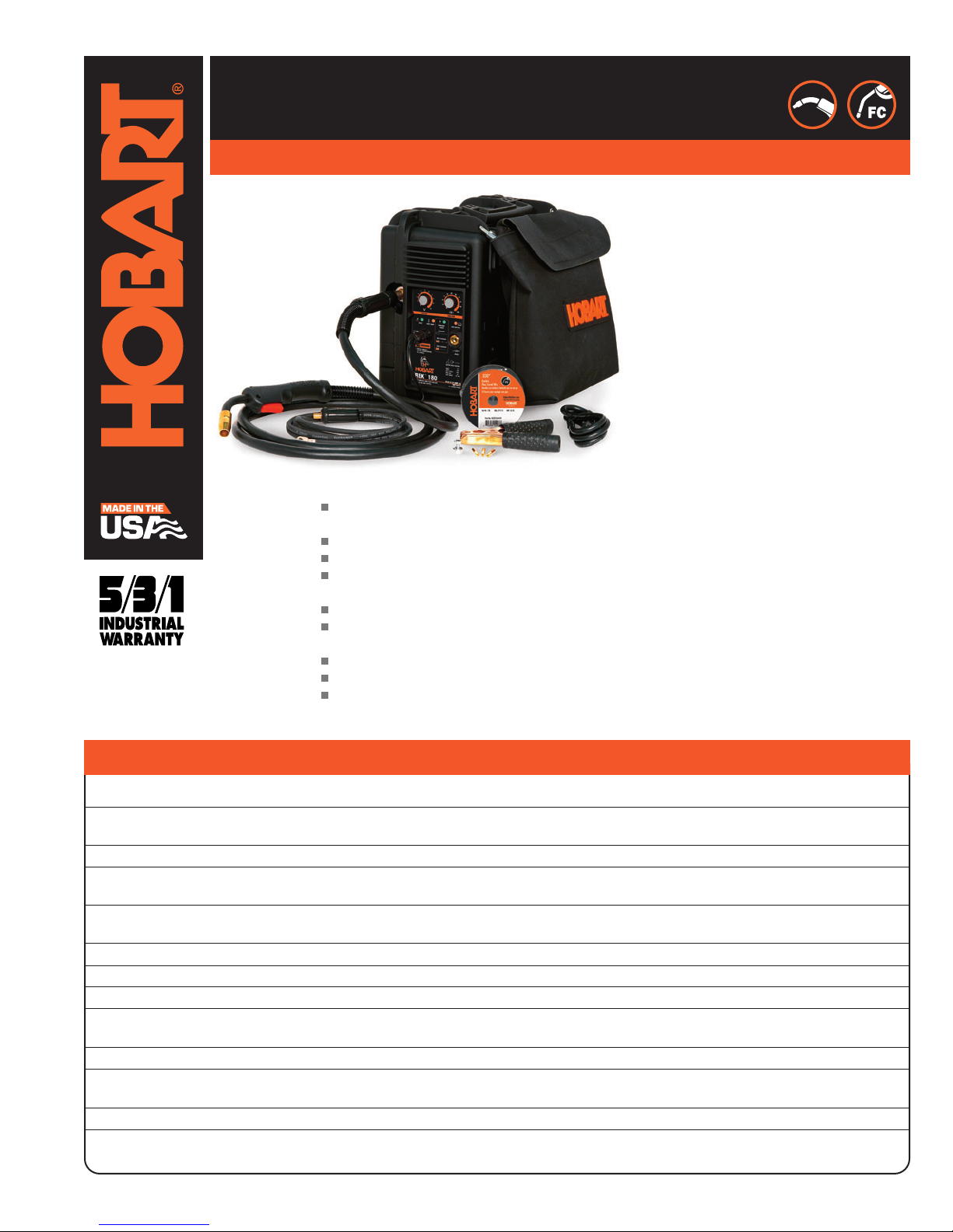
he TREK 180 battery-powered, inverter-based
wire welder is the first professional system on
the market for MIG welding “off the power grid.”
No matter where your hobby or job takes you, the
TREK delivers heavy-duty weld power to fabricate or
repair 24 ga. up to 1/4 in. mild steel in a single pass.
Powered by two internal, premium high-performance,
sealed lead-acid batteries, the high-purity energy
storage technology enables the TREK to be charged
complete in about 90 minutes and quickly recharged
in about 20 minutes. The unit delivers approx. 100
inches of weld bead when fully charged (using .030
diameter flux-cored wire on 1/8 in. mild steel.)
The integrated charging system is powered by a
standard 115 volt household receptacle. The machine
can operate while plugged in or completely cordless.
The TREK delivers 180 amps (approx. 12% duty cycle)
on 115 volt standard power… a weld output which,
until TREK, has been limited to 230 volt welders.
The TREK 180 can be charged inside a vehicle using
an automotive power inverter (400 continuous watt
minimum/charging times increase slightly.) The weld
output is regulated to provide consistent welding
voltage regardless of battery level. The unit is setup
for both self-shielded flux-cored and solid gasshielded wires from .024 to the .035 diameter. A
removable storage bag provides cable management
of standard MIG gun, work cable, clamp and
removable power cord. Impact-resistant case
provides strength and durability, protecting the
internal components and welding wire.
TREK™180
Battery-Powered MIG Welding Package
245164
Nov. 2010
Features Benefits
Includes:
Pouch for storage of MIG gun and work lead during
transportation
Comfortable 10 ft. H100L4-10 MIG torch
10 ft. work lead with clamp
2 premium high-performance sealed lead-acid
batteries
Spare .030 in. (0.8 mm) contact tips
Sample spool of .030 in. (0.8 mm) self-shielded
flux cored welding wire
Weld set-up and information chart
Removable power/recharging cord with plug
Owner’s Manual with parts lists, installation,
operation, maintenance and MIG welding guidelines
#500539
Inverter arc control technology for a smooth and stable arc.
Provides positive feed with adjustable tension. Easy access for threading wire.
Disables the welder when the battery runs low to protect the life of the battery.
Scans the available input charging power to compensate line draw for low capacity devices such as
small automotive inverters.
Provides a broader operating window for each wire with quick and easy adjustment for different materials
and thicknesses.
Quick and easy polarity change access for solid or tubular wire.
Easy to change from one wire size to another .023/.025 in. (0.6 mm) or .030–.035 in. (0.8–0.9 mm).
Diagnostic lights for quick information on the temperature, charging and battery status.
Thin plate pure lead (TPPL) technology allows for fast recharge (only 20 minutes).
Protects unit against current overload.
Protects power circuitry against thermal overload to ensure reliability.
Protects wire feed system from overload, no fuses to change or circuit breaker buttons to press.
Five-year warranty on transformers, stabilizers and generators; three years on electronics (drive motors,
rectifiers); and one year on guns (MIG and plasma torches).
Excellent arc performance
Proven built-in wire feeder with
quick-release tension lever
Low battery shutdown
“AutoPower
™
” technology
Infinite voltage and wire control
Convenient polarity changeover
Quick-change, dual-groove drive roll
LED indicators
High-performance sealed
lead batteries
Short circuit protection
Self-resetting thermal overload
protection
Self-resetting motor protection
Hobart’s 5/3/1 Industrial Warranty
Page 2
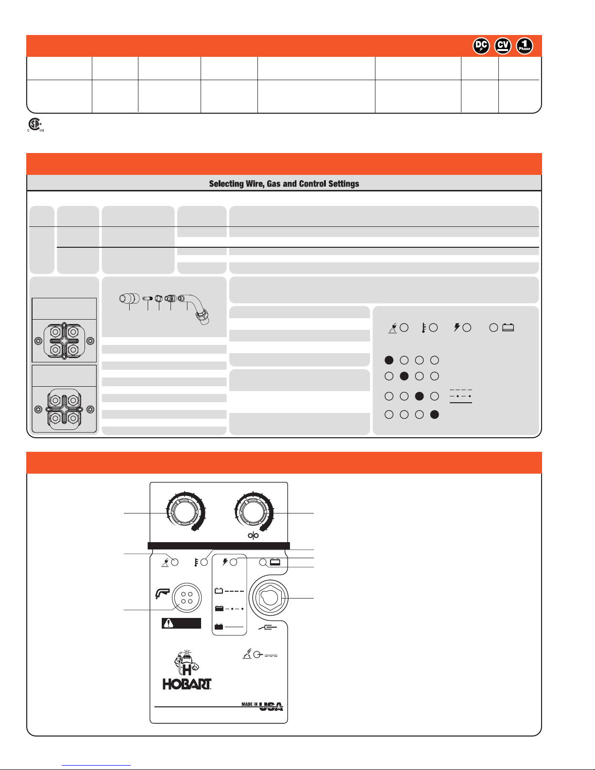
Control Panel
C25 Gas Mixture
75% Ar / 25% CO
2
Produces Less Spatter
Better Appearance
No Shielding Gas Required
Good for Windy or
Outdoor Applications
Flux Core
E71T-GS
(DCEN)
Solid Wire
ER70S-6
(DCEP)
Steel
Welding Gun Consumables
169715
226190
Stock No.
170470
169716
242831
194011
194010
000068
087299
000067
.500” orf flush
Flux Cored
A) Nozzles
C) Retaining Ring
D) Contact Tip Adaptor
Liners
.030” / .035”
.023” / .025”
E) Head Tube
.035” ( 0.9mm )
B) Tips
.023” ( 0.6mm )
.030” ( 0.8mm )
A
B C D E
LED Status
See Owner’s Manual for Other LED Combinations
READY LOW BATTERYOVER TEMP CHARGING
STATUS
Unit is charged, ready to weld
Batteries Charging
Batteries 80% Charged
Batteries Fully Charged
Low Battery, plug in welder to charge
Over Temp has occurred, stop welding
and allow unit to cool down
Changing
Polarity
DCEN
Electrode Negative
For Flux Cored Wire
DCEP
Electrode Positive
For Solid Wire
Drive Rolls
V – Groove
.024” - .030” / .035”
( 0.6mm - 0.8mm / 0.9mm )
237338
VK – Groove
.030” / .035” - .045”
( 0.8mm / 0.9mm - 1.2mm )
202926
Dual Grooved
Groove
Wire
Size
Stock
No.
See Owner’s Manual
Match drive roll groove to diameter of wire being used.
Settings are approximate. Adjust as required. Thicker materials can be
welded using proper technique, joint preparation and multiple passes.
Recommended Voltage and Wire Speed Settings for Thickness of Metal Being Welded
Number on Left is Voltage Setting / Number on Right is Wire Feed Setting
Diameter
of Wire
Being Used
Suggested
Shielding Gases
20–30 cfh Flow Rate
Wire Type,
and
Polarity Setting
Material
Being
Welded
24 gauge
.024 inch
( 0.6 mm )
22 gauge
.030 inch
( 0.8 mm )
20 gauge
.036 inch
( 0.9 mm )
18 gauge
.048 inch
( 1.2 mm )
16 gauge
.060 inch
( 1.5 mm )
14 gauge
.075 inch
( 1.9 mm )
12 gauge
.105 inch
( 2.7 mm )
1/8 inch
( 3.2 mm )
3/16 inch
( 4.8 mm )
1/4 inch
( 6.4 mm )
5/16 inch
( 7.9 mm )
.030” ( 0.8 mm ) — — — 1 / 0 2 / 5 3 / 10 5 / 30 6 / 40 8 / 70 10 / 100 —
.024” ( 0.6 mm )
0 / 20 0 / 30 2 / 40 4 / 40 7 / 60 8 / 80 10 / 100 10 / 100 — — —
.030” ( 0.8 mm ) — 0 / 10 1 / 10 2 / 20 3 / 30 3 / 40 5 / 50 7 / 50 10 / 60 10 / 60 —
.035” ( 0.9 mm ) — — — — 3 / 10 5 / 20 6 / 25 7 / 30 9 / 35 10 / 40 —
• Set Tension Knob Setting to 3 at start. Adjust tension per instructions in the manual.
• Wire Speed listed is a starting value only. Wire speed setting can be fine-tuned while welding. Wire speed
also depends on other variables such as stick out, travel speed, weld angle, cleanliness of metal, etc.
232680-A
.035” ( 0.9 mm )
— — — — — — — 5 / 20 8 / 40 10 / 50 10 / 60
For Maximum Battery Life, Unit Should Be
Plugged In When Not In Use
Battery Must Be Recharged After Each Use.
USE ONLY FACTORY AUTHORIZED BATTERIES
Stock No. 232612
TREK 180 Welding Guide
2
Rated Output
120 A, 17 VDC at
20% Duty Cycle
Max. Open
Circuit Voltage
30 V
Current
Range
25–180 A
Dimensions
H: 13-5/16 in. (338 mm)
W: 17 in. (433 mm)
D: 7-7/8 in. (200 mm)
Wire Feed
Speed Range
40–400 IPM
Net
Weight
51.87 lb.
(23.5 kg)
Shipping
Weight
61 lb.
(27.7 kg)
Amps Input at Rated Load, 60 Hz
115 V KVA KW
12* 1.38 0.75
*
Auto Power™ technology will adjust as low as 3.5 A based on input power available.
Specifications
(SUBJECT TO CHANGE WITHOUT NOTICE.)
V
1
2
3
4
5
6
7
8
9
10
10
20
30
40
50
60
70
80
90
100
READY LOW BATTERYOVER TEMP CHARGING
STATUS
TRIGGER
WORK
CHARGING
80% CHARGED
100% CHARGED
TREK TM 180
BATTERY POWERED WIRE FEED WELDER
25-180 AMP OUTPUT
WARNING
• UNPLUG TRIGGER
BEFORE TRANSPORTING
OR STORING.
VOLTAGE WIRE FEED
VOLTS
AMPS
DUTY CYCLE
MAX OCV
AMP RANGE
17
120
20%
30
25-180
RATED WELD OUTPUT
1
3
7
4
5
6
2
8
1. Voltage Control
2. Welder Ready Light
3. Trigger Receptacle
4. Wire Speed Control
5. Over Temperature Light
6. Charging Status Light
7. Battery Status Light
8. Work Lead Receptacle
Certified by Canadian Standards Association to both Canadian and U.S. Standards.
Page 3

Performance Data
Accessories
3
DUTY CYCLE CHART
(WHILE OPERATING CONNECTED TO A 115V SUPPLY)
0
20
40
60
80
100
120
140
160
180
200
0 10 20 30 40 50 60 70 80 90 100
% DUTY CYCLE
DC AMPERES
TREK 180 VA CURVES
0
5
10
15
20
25
30
0 20 40 60 80 100 120 140 160 180 200
DC AMPERES
DC VOLTS
Minimum
Maximum
WELD TIME WHILE OPERATING FROM BATTERIES ONLY
1
2
3
4
5
10
20
30
100
0 20 40 60 80 100 120 140 160 180 200
DC AMPERES
WELD TIME (MINUTES)
20 Ga. 18 Ga. 16 Ga. 1/8" 3/16" 1/4"
H100L4-10 Replacement MIG Torch
#243864
For .030–.035 in. (0.8–0.9 mm) wire.
Includes 10 ft. (3 m) cable.
Drive Rolls
Dual-Groove, V-Smooth #237338
For .023/.025 in. (0.6 mm) and .030 –.035 in.
(0.8–0.9 mm) wire.
Dual-Groove, V-Knurled #202926
For .030–.035 in. (0.8–0.9 mm) and .045 in.
(1.2 mm) flux-cored wire.
Contact Tips
(See chart on back page.)
MIG Nozzle
(See chart on back page.)
Protects tip adapter and
focuses gas coverage.
Gasless Flux-cored
Nozzle
(See chart on back page.)
For use with self-shielding
flux-cored wires. Improves
visibility, eases access in
tight corners, protects tip adapter/gas diffuser
from spatter and from shorting to the work piece.
For use with H9, H10, M10, and M15 torches.
Tip Adapter
(See chart on back page.)
Replacement Liners
(See chart on back page.)
Page 4

Hobart Welders An Illinois Tool Works Company hobartwelders.com
Hobart Welding Products Service 800-332-3281 Sales 800-626-9420
Litho in USA
Item Hobart Package Part #* Miller Package Part #**
Contact Tips
.023/.025 in. (0.6 mm) #770174 (5 per package) #087 299 (10 per package)
.030 in. (0.8 mm) #770177 (5 per package) #000 067 (10 per package)
.035 in. (0.9 mm) #770180 (5 per package) #000 068 (10 per package)
MIG Nozzle (Standard) #770404 #169 715
Gasless Flux Cored Nozzle #770487 #226 190
Tip Adapter #770402 #169 716
Replacement Liners
.023/.025 in. (0.6 mm) #196139 #194 010
.030/.035 in. (0.8/0.9 mm) #196139 #194 011
.035/.045 in. (0.9/1.2 mm) #196140 #194 012
*Available at farm and tool supply retailers. **Available at Hobart/Miller welding distributors.
Consumables
 Loading...