


WJ200

WJ200
Series Inverter
Quick Reference Guide
• Single-phase Input 200V class
• Three-phase Input 200V class
• Three-phase Input 400V class
Hitachi Industrial Equipment Systems Co., Ltd.
Manual Number: NT3251X
May 2010
Refer to the user manual for detail


1
UL Cautions, Warnings and Instructions xii
Warnings and Cautions for Troubleshooting and Maintenance
The warnings and instructions in this section summarizes the procedures necessary to ensure an
inverter installation complies with Underwriters Laboratories
guidelines.
WARNING: Use 60/75C Cu wire only. (for models: WJ200-001L, 002L, 004L, 007L, 015S, 022S,
004H, 007H, 015H, 022H, 030H)
WARNING: Use 75C Cu wire only. (for models: WJ200-001S, -002S, -004S, -007S, -015L, -022L,
-037L, -055L, -075L, -110L, -150L, -040H, -055H, -075H, -110H and -150H)
WARNING: Suitable for use on a circuit capable of delivering not more than 100,000 rms
Symmetrical Amperes, 240 or 480V maximum.
WARNING: When protected by CC, G, J, or R class Fuses, or when Protected By A Circuit Breaker
Having An Interrupting Rating Not Less Than 100,000 rms Symmetrical Amperes, 240 or 480 Volts
Maximum.
WARNING: Install device in pollution degree 2 environment.
WARNING: Maximum Surrounding Air Temperature 50C
WARNING: Solid state motor overload protection is provided in each model
WARNING: Integral solid state short circuit protection does not provide branch circuit protection.
Branch circuit protection must be provided in accordance with the National Electric Code and any
additional local codes

2
Terminal symbols and Screw size
Inverter Model Screw Size
Required
Torque (N-m)
Wire range
WJ200-001S
WJ200-002S
WJ200-004S
M3.5 1.0 AWG16 (1.3mm
2
)
WJ200-007S M4 1.4 AWG12 (3.3mm
2
)
WJ200-015S
WJ200-022S
M4 1.4 AWG10 (5.3mm
2
)
WJ200-001L
WJ200-002L
WJ200-004L
WJ200-007L
M3.5 1.0 AWG16 (1.3mm
2
)
WJ200-015L M4 1.4 AWG14 (2.1mm
2
)
WJ200-022L M4 1.4 AWG12 (3.3mm
2
)
WJ200-037L M4 1.4 AWG10 (5.3mm
2
)
WJ200-055L
WJ200-075L
M5 3.0 AWG6 (13mm
2
)
WJ200-110L M6 3.9 to 5.1 AWG4 (21mm
2
)
WJ200-150L M8 5.9 to 8.8 AWG2 (34mm
2
)
WJ200-004H
WJ200-007H
WJ200-015H
M4 1.4 AWG16 (1.3mm
2
)
WJ200-022H
WJ200-030H
M4 1.4 AWG14 (2.1mm
2
)
WJ200-040H M4 1.4 AWG12 (3.3mm
2
)
WJ200-055H
WJ200-075H
M5 3.0 AWG10 (5.3mm
2
)
WJ200-110H
WJ200-150H
M6 3.9 to 5.1 AWG6 (13mm
2
)

3
Fuse Sizes
The inverter shall be connected with a UL Listed Cartridge Nonrenewable fuse, rated
600Vac with the current ratings as shown in the table below.
Inverter Model Type Rating
WJ200-001S
WJ200-002S
WJ200-004S
10A, AIC 200kA
WJ200-007S 15A, AIC 200kA
WJ200-015S
WJ200-022S
30A, AIC 200kA
WJ200-001L
WJ200-002L
WJ200-004L
10A, AIC 200kA
WJ200-007L
WJ200-015L
15A, AIC 200kA
WJ200-022L 20A, AIC 200kA
WJ200-037L 30A, AIC 200kA
WJ200-055L
WJ200-075L
40A, AIC 200kA
WJ200-110L
WJ200-150L
80A, AIC 200kA
WJ200-004H
WJ200-007H
WJ200-015H
WJ200-022H
10A, AIC 200kA
WJ200-030H
WJ200-040H
15A, AIC 200kA
WJ200-055H
WJ200-075H
20A, AIC 200kA
WJ200-110H
WJ200-150H
Class J
40A, AIC 200kA
4
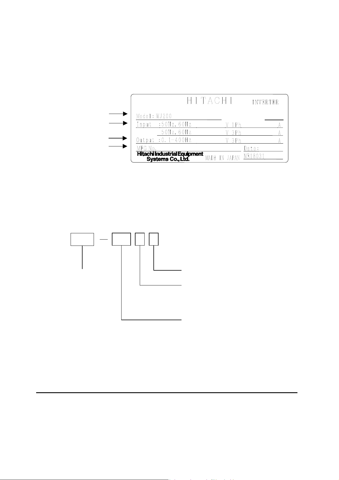
Inverter Specification Label
The Hitachi WJ200 inverters have product labels located on the right side of the housing,
as pictured below. Be sure to verify that the specifications on the labels match your power
source, and application safety requirements.
Inverter Specification Label
The model number for a specific inverter contains useful information about its operating
characteristics. Refer to the model number legend below:
WJ200
001 S F
Series name
Configuration type
F=with keypad
Input voltage:
S=Single-phase 200V class
L=Three-phase 200V class
H=Three-phase 400V class
A
pplicable motor capacity in kW
001=0.1kW 037=3.7kW
002=0.2kW 040=4.0kW
004=0.4kW 055=5.5kW
007=0.75kW 075=7.5kW
015=1.5kW 110=11kW
022=2.2kW 150=15kW
030=3.0kW
200-240
200-240
2.0/1.3
1.2
/
1. 0
1005
05A
_
T12345
_
A
_
-001
-001SF
Model name
Input ratings
Output ratings
MFG number
Ver:2.0

5
WJ200 Inverter Specifications
Model-specific tables for 200V and 400V class inverters
The following tables are specific to WJ200 inverters for the 200V and 400V class model
groups. Note that “General Specifications” on page in this chapter
apply to both voltage
class groups. Footnotes for all specification tables follow the table below.
Item Single-phase 200V class Specifications
WJ200 inverters, 200V models 001SF 002SF 004SF 007SF 015SF 022SF
VT 0.2 0.4 0.55 1.1 2.2 3.0 kW
CT 0.1 0.2 0.4 0.75 1.5 2.2
VT
1/4 1/2 3/4 1.5 3 4
Applicable motor size
*2
HP
CT
1/8 1/4 1/2 1 2 3
VT 0.4 0.6 1.2 2.0 3.3 4.1 200V
CT 0.2 0.5 1.0 1.7 2.7 3.8
VT 0.4 0.7 1.4 2.4 3.9 4.9
Rated capacity (kVA)
240V
CT 0.3 0.6 1.2 2.0 3.3 4.5
Rated input voltage
Single-phase: 200V-15% to 240V +10%, 50/60Hz 5%
Rated output voltage *3 3-phase: 200 to 240V (proportional to input voltage)
VT 1.2 1.9 3.5 6.0 9.6 12.0 Rated output current (A)
CT 1.0 1.6 3.0 5.0 8.0 11.0
Starting torque *6 200% at 0.5Hz
Without resistor
100%:
50Hz
50%:
60Hz
70%:
50Hz
50%:
60Hz
20%:
50Hz
20%:
60Hz
Braking
With resistor 150% 100%
DC braking Variable operating frequency, time, and braking force
kg 1.0 1.0 1.1 1.6 1.8 1.8 Weight
lb 2.2 2.2 2.4 3.5 4.0 4.0

6
WJ200 Inverter Specifications, continued…
Item Three-phase 200V class Specifications
WJ200 inverters, 200V models
001LF 002LF 004LF 007LF 015LF 022LF
VT 0.2 0.4 0.75 1.1 2.2 3.0 kW
CT 0.1 0.2 0.4 0.75 1.5 2.2
VT
1/4 1/2 1 1.5 3 4
Applicable motor size *2
HP
CT
1/8 1/4 1/2 1 2 3
VT 0.4 0.6 1.2 2.0 3.3 4.1 200V
CT 0.2 0.5 1.0 1.7 2.7 3.8
VT 0.4 0.7 1.4 2.4 3.9 4.9
Rated capacity (kVA)
240V
CT 0.3 0.6 1.2 2.0 3.3 4.5
Rated input voltage
Three-phase: 200V-15% to 240V +10%, 50/60Hz 5%
Rated output voltage *3 Three-phase: 200 to 240V (proportional to input voltage)
VT 1.2 1.9 3.5 6.0 9.6 12.0 Rated output current (A)
CT 1.0 1.6 3.0 5.0 8.0 11.0
Starting torque *6 200% at 0.5Hz
Without resistor
100%:
50Hz
50%:
60Hz
70%:
50Hz
50%:
60Hz
20%:
50Hz
20%:
60Hz
Braking
With resistor 150% 100%
DC braking Variable operating frequency, time, and braking force
kg 1.0 1.0 1.1 1.2 1.6 1.8 Weight
lb 2.2 2.2 2.4 2.6 3.5 4.0
Item Three-phase 200V class Specifications
WJ200 inverters, 200V models
037LF 055LF 075LF 110LF 150LF
VT 5.5 7.5 11 15 18.5 kW
CT 3.7 5.5 7.5 11 15
VT
7.5 10 15 20 25
Applicable motor size *2
HP
CT
5 7.5 10 15 20
VT 6.7 10.3 13.8 19.3 20.7 200V
CT 6.0 8.6 11.4 16.2 20.7
VT 8.1 12.4 16.6 23.2 24.9
Rated capacity (kVA)
240V
CT 7.2 10.3 13.7 19.5 24.9
Rated input voltage
Single-phase: 200V-15% to 240V +10%, 50/60Hz 5%
Rated output voltage *3 3-phase: 200 to 240V (proportional to input voltage)
VT 19.6 30.0 40.0 56.0 69.0 Rated output current (A)
CT 17.5 25.0 33.0 47.0 60.0
Starting torque *6 200% at 0.5Hz
Without resistor
100%:
50Hz
50%:
60Hz
70%:
50Hz
50%:
60Hz
Braking
With resistor 150%
DC braking Variable operating frequency, time, and braking force
Kg 2.0 3.3 3.4 5.1 7.4 Weight
lb 4.4 7.3 7.5 11.2 16.3
7
WJ200 Inverter Specifications, continued…
Item Three-phase 400V class Specifications
WJ200 inverters, 400V models
004HF 007HF 015HF 022HF 030HF 040HF
VT 0.75 1.5 2.2 3.0 4.0 5.5 kW
CT 0.4 0.75 1.5 2.2 3.0 4.0
VT 1 2 3 4 5 7.5
Applicable motor size *2
HP
CT 1/2 1 2 3 4 5
VT 1.3 2.6 3.5 4.5 5.7 7.3 380V
CT 1.1 2.2 3.1 3.6 4.7 6.0
VT 1.7 3.4 4.4 5.7 7.3 9.2
Rated capacity (kVA)
480V
CT 1.4 2.8 3.9 4.5 5.9 7.6
Rated input voltage
Three-phase: 200V-15% to 240V +10%, 50/60Hz 5%
Rated output voltage *3 Three-phase: 200 to 240V (proportional to input voltage)
VT 2.1 4.1 5.4 6.9 8.8 11.1 Rated output current (A)
CT 1.8 3.4 4.8 5.5 7.2 9.2
Starting torque *6 200% at 0.5Hz
Without resistor
100%:
50Hz
50%:
60Hz
70%:
50Hz
50%:
60Hz
Braking
With resistor 150%
DC braking Variable operating frequency, time, and braking force
kg 1.5 1.6 1.8 1.9 1.9 2.1 Weight
lb 3.3 3.5 4.0 4.2 4.2 4.6
Item Three-phase 400V class Specifications
WJ200 inverters, 400V models
055HF 075HF 110HF 150HF
VT 7.5 11 15 18.5 kW
CT 5.5 7.5 11 15
VT 10 15 20 25
Applicable motor size *2
HP
CT 7.5 10 15 20
VT 11.5 15.1 20.4 25.0 380V
CT 9.7 11.8 15.7 20.4
VT 14.5 19.1 25.7 31.5
Rated capacity (kVA)
480V
CT 12.3 14.9 19.9 25.7
Rated input voltage
Single-phase: 200V-15% to 240V +10%, 50/60Hz 5%
Rated output voltage *3 3-phase: 200 to 240V (proportional to input voltage)
VT 17.5 23.0 31.0 38.0 Rated output current (A)
CT 14.8 18.0 24.0 31.0
Starting torque *6 200% at 0.5Hz
Without resistor
100%:
50Hz
50%:
60Hz
Braking
With resistor 150%
DC braking Variable operating frequency, time, and braking force
kg 3.5 3.5 4.7 5.2 Weight
lb 7.7 7.7 10.4 11.5

8
The following table shows which models need derating.
1-ph 200V class Need
derating
3-ph 200V class Need
derating
3-ph 400V class Need
derating
WJ200-001S
−
WJ200-001L
−
WJ200-004H
9
WJ200-002S
−
WJ200-002L
9
WJ200-007H
9
WJ200-004S
9
WJ200-004L
9
WJ200-015H
−
WJ200-007S
9
WJ200-007L
−
WJ200-022H
−
WJ200-015S
−
WJ200-015L
−
WJ200-030H
−
WJ200-022S
−
WJ200-022L
−
WJ200-040H
9
− −
WJ200-037L
9
WJ200-055H
−
− −
WJ200-055L
−
WJ200-075H
9
− −
WJ200-075L
9
WJ200-110H
9
− −
WJ200-110L
9
WJ200-150H
9
− −
WJ200-150L
9
− −
9:need derating
−:need no derating
Use the following derating curves to help determine the optimal carrier frequency setting
for your inverter and find the output current derating. Be sure to use the proper curve for
your particular WJ200 inverter model number.
9
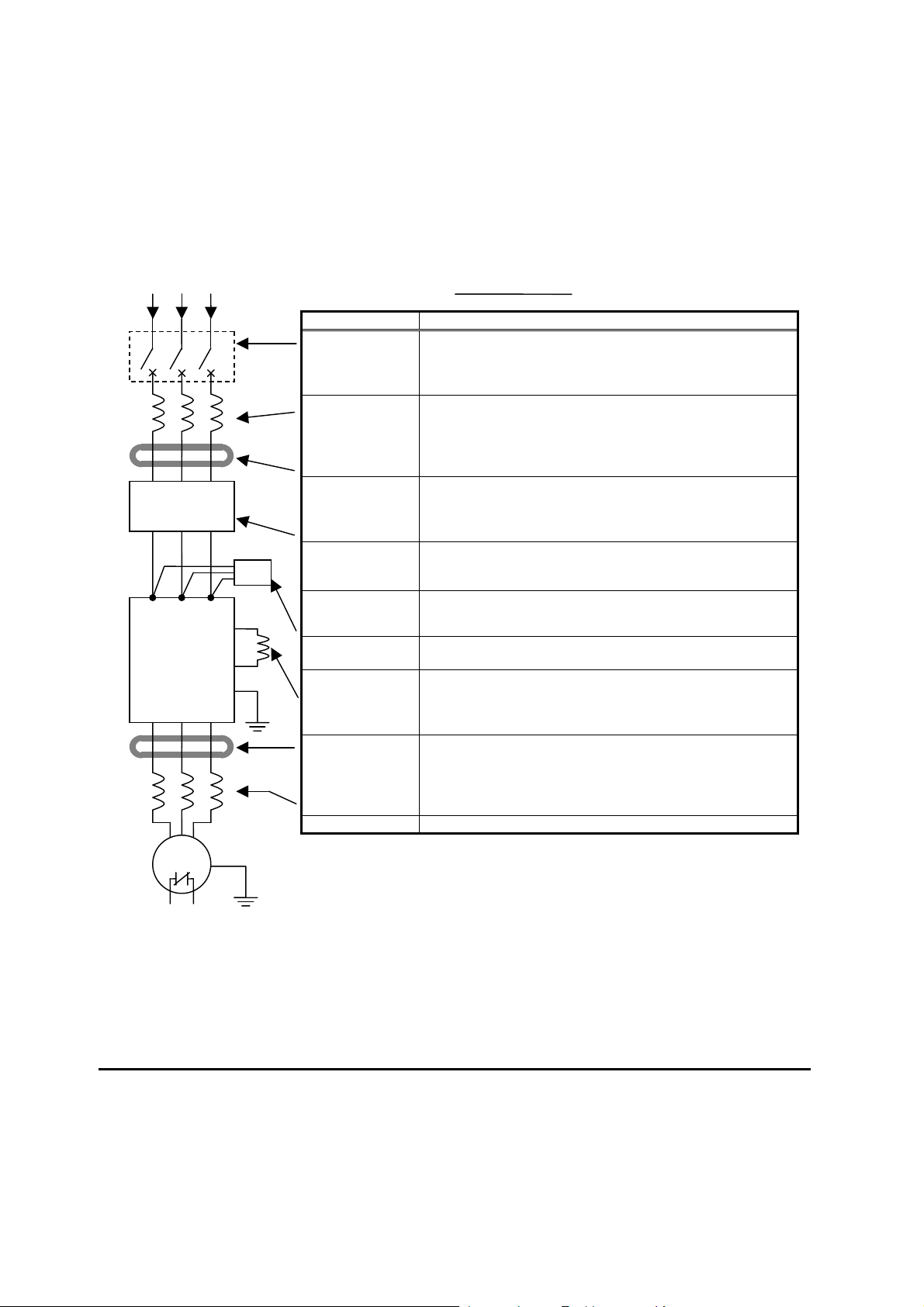
Basic System Description
A motor control system will obviously include a motor and inverter, as well as a circuit
breaker or fuses for safety. If you are connecting a motor to the inverter on a test bench
just to get started, that’s all you may need for now. But a system can also have a variety of
additional components. Some can be for noise suppression, while others may enhance the
inverter’s braking performance. The figure and table below show a system with all the
optional components you might need in your finished application.
Name Function
Breaker /
disconnect
A molded-case circuit breaker (MCCB), ground fault
interrupter (GFI), or a fused disconnect device. NOTE: The
installer must refer to the NEC and local codes to ensure
safety and compliance.
Input-side
AC Reactor
This is useful in suppressing harmonics induced on the
power supply lines and for improving the power factor.
WARNING: Some applications must use an input-side AC
Reactor to prevent inverter damage. See Warning on next
page.
Radio noise filter
Electrical noise interference may occur on nearby
equipment such as a radio receiver. This magnetic choke
filter helps reduce radiated noise (can also be used on
output).
EMC filter (for
CE applications,
see Appendix D)
Reduces the conducted noise on the power supply wiring
between the inverter and the power distribution system.
Connect to the inverter primary (input) side.
Radio noise filter
(use in non-CE
applications)
This capacitive filter reduces radiated noise from the main
power wires in the inverter input side.
DC link choke
Suppress harmonics generated by the inverter. However, it
will not protect the input diode bridge rectifier.
Radio noise filter
Electrical noise interference may occur on nearby
equipment such as a radio receiver. This magnetic choke
filter helps reduce radiated noise (can also be used on
input).
Output-side
AC Reactor
This reactor reduces the vibration in the motor caused by
the inverter’s switching waveforms, by smoothing the
waveform to approximate commercial power quality. It is
also useful to reduce harmonics when wiring from the
inverter to the motor is more than 10m in length.
LCR filter
Sine wave shaping filter for output side.
Breaker,
MCCB or
GFI
From power supply
Motor
Thermal
switch
L1 L2 L3
T1 T2 T3
Inverter
+1
+
GND

10
Determining Wire and Fuse Sizes
The maximum motor currents in your application determines the recommended wore size.
The following table gives the wire size in AWG. The “Power Lines” column applies to the
inverter input power, output wires to the motor, the earth ground connection, and any other
components shown in the “Basic System Description” on page 2-7. The “Signal Lines”
column applies to any wire connecting to the two green connectors just inside the front
cover panel.
Motor Output Wiring
Applicable
equipment
kW HP
VT CT VT CT
Inverter Model
Power Lines Signal Lines
Fuse (UL-rated,
class J, 600V ,
Maximum
allowable current)
0.2 0.1 ¼ 1/8
WJ200-001SF
0.4 0.2 ½ ¼
WJ200-002SF
0.55
0.4 ¾ ½
WJ200-004SF
AWG16 / 1.3mm
2
(75C only)
10A
1.1
0.75
1.5 1
WJ200-007SF
AWG12 / 3.3mm
2
(75C only)
20A
2.2 1.5 3 2
WJ200-015SF
3.0 2.2 4 3
WJ200-022SF
AWG10 / 5.3mm
2
30A
0.2 0.1 ¼ 1/8
WJ200-001LF
0.4 0.2 ½ ¼
WJ200-002LF
0.75
0.4 1 ½
WJ200-004LF
10A
1.1
0.75
1.5 1
WJ200-007LF
AWG16 / 1.3mm
2
2.2 1.5 3 2
WJ200-015LF
AWG14 / 2.1mm
2
(75C only)
15A
3.0 2.2 4 3
WJ200-022LF
AWG12 / 3.3mm
2
(75C only)
20A
5.5 3.7 7.5 5
WJ200-037LF
AWG10 / 5.3mm
2
(75C only)
30A
7.5 5.5 10 7.5
WJ200-055LF
11 7.5 15 10
WJ200-075LF
AWG6 / 13mm
2
(75C only)
60A
15 11 20 15
WJ200-110LF
AWG4 / 21mm
2
(75C only)
80A
18.5
15 25 20
WJ200-150LF
AWG2 / 34mm
2
(75C only)
80A
0.75
0.4 1 ½
WJ200-004HF
1.5
0.75
2 1
WJ200-007HF
2.2 1.5 3 2
WJ200-015HF
AWG16 / 1.3mm
2
3.0 2.2 4 3
WJ200-022HF
10A
4.0 3.0 5 4
WJ200-030HF
AWG14 / 2.1mm
2
5.5 4.0 7.5 5
WJ200-040HF
AWG12 / 3.3mm
2
(75C only)
15A
7.5 5.5 10 7.5
WJ200-055HF
11 7.5 15 10
WJ200-075HF
AWG10/ 5.3mm
2
(75C only)
30A
15 11 20 15
WJ200-110HF
AWG6 / 13mm
2
(75C only)
50A
18.5
15 25 20
WJ200-150HF
AWG6 / 13mm
2
(75C only)
18 to 28
AWG / 0.14
to 0.75 mm
2
shielded wire
(see Note 4)
50A
Note 1: Field wiring must be made by a UL-Listed and CSA-certified closed-loop terminal
connector sized for the wire gauge involved. Connector must be fixed by using
the crimping tool specified by the connector manufacturer.
Note 2: Be sure to consider the capacity of the circuit breaker to be used.
Note 3: Be sure to use a larger wire gauge if power line length exceeds 66ft. (20m).
Note 4: Use 18 AWG / 0.75mm
2
wire for the alarm signal wire ([AL0], [AL1], [AL2]
terminals).
11
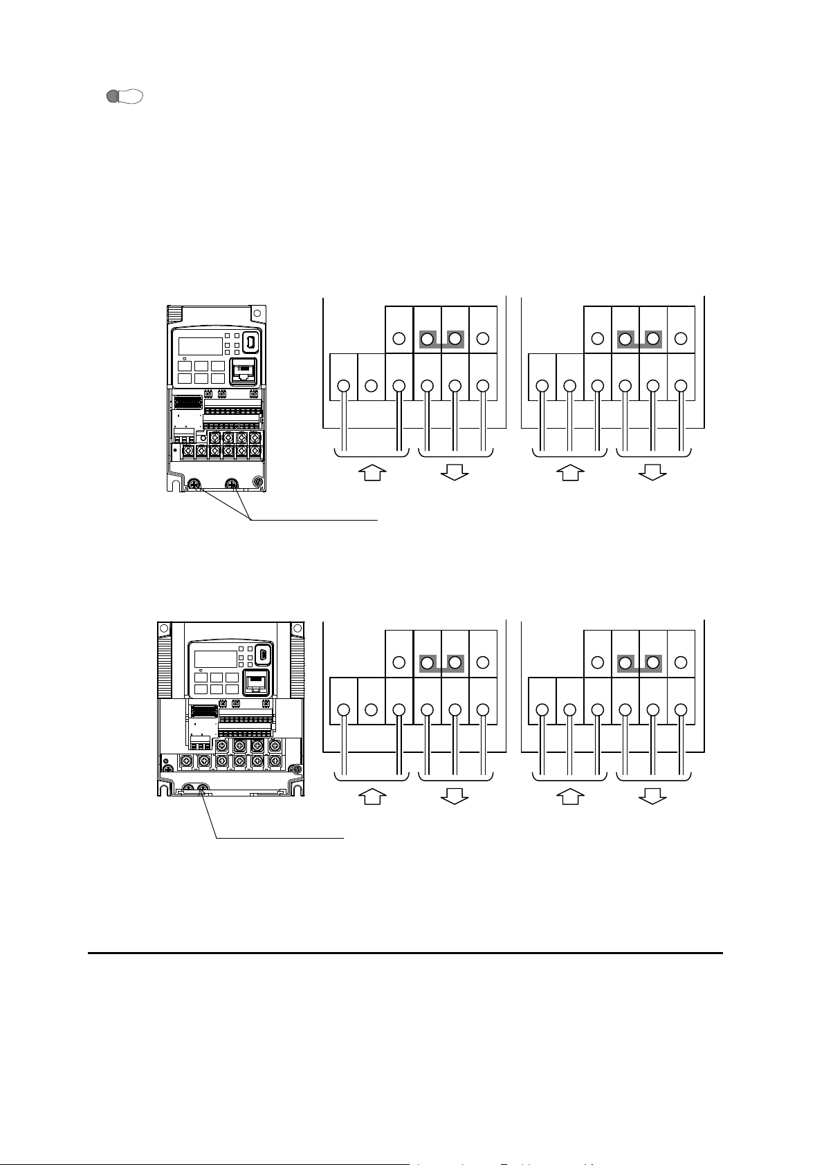
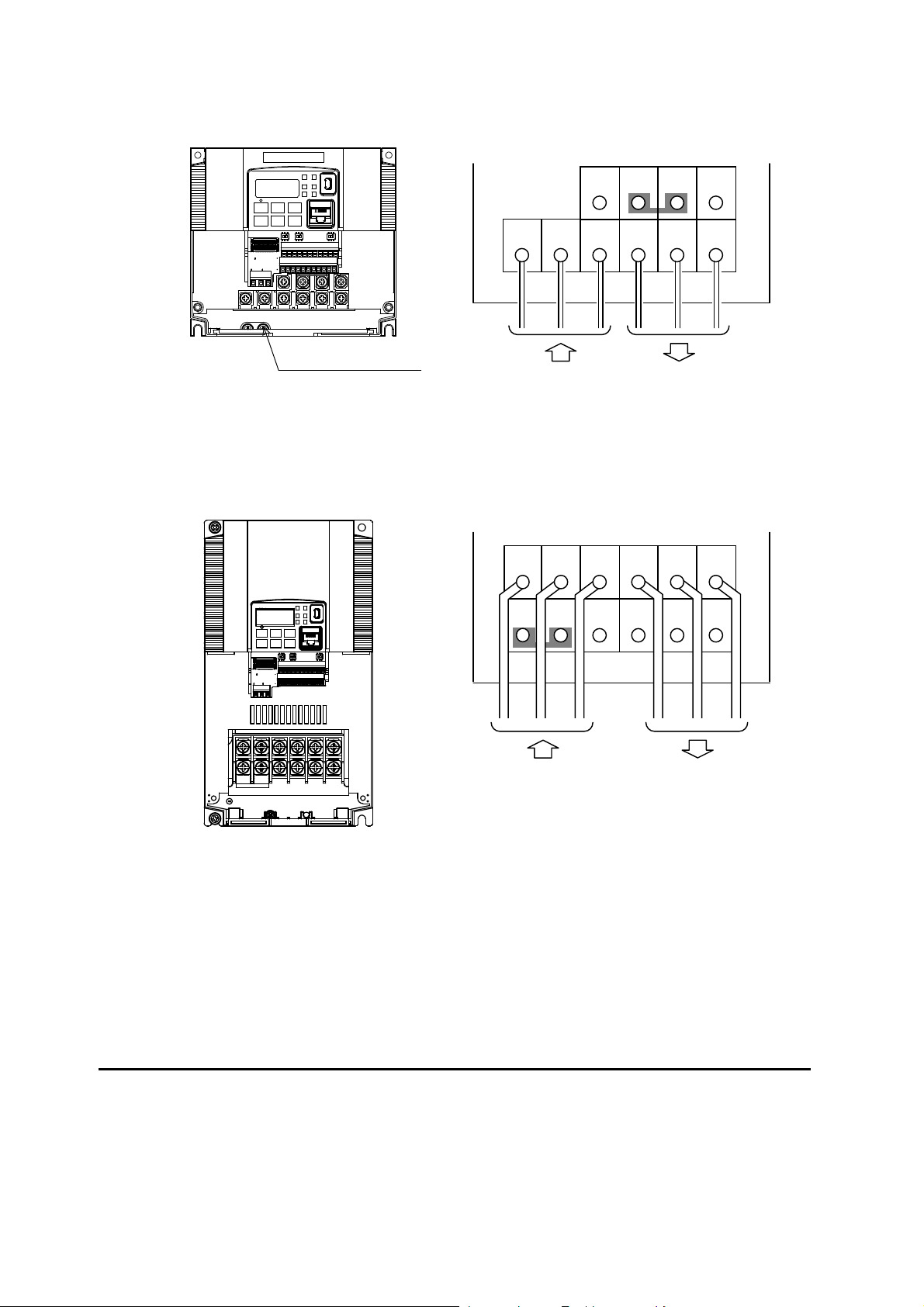
Wire the Inverter Input to a Supply
Step 6: In this step, you will connect wiring to the input of the inverter. First, you must
determine whether the inverter model you have required three-phase power only, or
single-phase power only. All models have the same power connection terminals [R/L1],
[S/L2], and [T/L3]. So you must refer to the specifications label (on the side of the
inverter) for the acceptable power source types! For inverters that can accept
single-phase power and are connected that way, terminal [S/L2] will remain
unconnected.
Note the use of ring lug connectors for a secure connection.
Single-phase 200V 0.1 to 0.4kW
Three-phase 200V 0.1 to 0.75kW
Single-phase 200V 0.75 to 2.2kW
Three-phase 200V 1.5, 2.2kW
Three-phase 400V 0.4 to 3.0kW
6
Chassis Ground (M4)
L1
Power input Output to Motor
N
U/T1
V/T2
W/T3
RB
+1
+
-
Single-phase Three-phase
R/L1
Power input Output to Motor
S/L2
T/L3 U/T1 V/T2 W/T3
RB
PD/+1
P/+ N/
-
Chassis Ground (M4)
L1
Power input Output to Motor
N
U/T1
V/T2
W/T3
RB
+1
+
-
Single-phase Three-phase
R/L1
Power input Output to Motor
S/L2
T/L3 U/T1 V/T2 W/T3
RB
PD/+1
P/+ N/
-
12
Three-phase 200V 3.7kW
Three-phase 400V 4.0kW
Three-phase 200V 5.5, 7.5kW
Three-phase 400V 5.5, 7.5kW
W/T3 V/T2 U/T1
T/L3
S/L2
R/L1
N/
-
P/+
PD/+1
RB
Power input Output to Motor
Chassis Ground (M4)
G G RB
N/
-
P/+
PD/+1
W/T3 V/T2 U/T1
T/L3
S/L2
R/L1
Power input Output to Motor
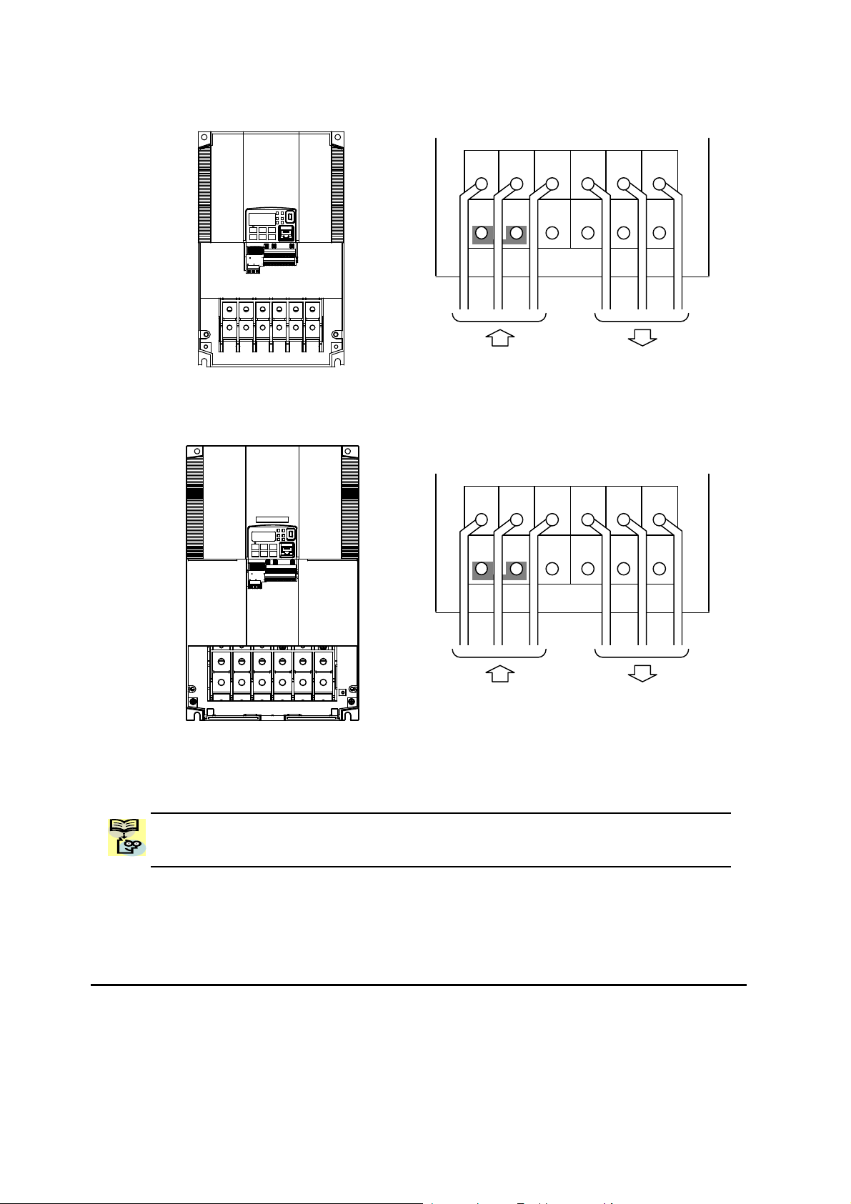
13
Three-phase 200V 11kW
Three-phase 400V 11, 15kW
Three-phase 200V 15kW
NOTE: An inverter powered by a portable power generator may receive a distorted power
waveform, overheating the generator. In general, the generator capacity should be five
times that of the inverter (kVA).
G G RB
N/
-
P/+
PD/+1
W/T3 V/T2 U/T1
T/L3
S/L2
R/L1
Power input Output to Motor
G G RB
N/
-
P/+
PD/+1
W/T3 V/T2 U/T1
T/L3
S/L2
R/L1
Power input Output to Motor
14
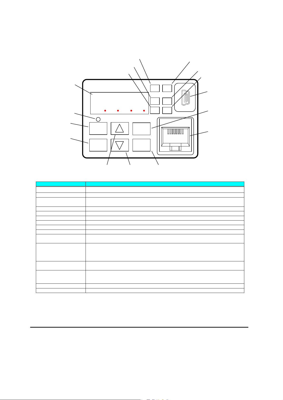
Using the Front Panel Keypad
Please take a moment to familiarize yourself with the keypad layout shown in the figure
below. The display is used in programming the inverter’s parameters, as well as monitoring
specific parameter values during operation.
Key and Indicator Legend
Items Contents
(1) POWER LED Turns ON (Green) while the inverter is powered up.
(2) ALARM LED Turns ON (Red) when the inverter trips.
(3) Program LED
¾ Turns ON (Green) when the display shows changeable parameter.
¾ Blinks when there is a mismatch in setting.
(4) RUN LED Turns ON (Green) when the inverter is driving the motor.
(5) Monitor LED [Hz] Turns ON (Green) when the displayed data is frequency related.
(6) Monitor LED [A] Turns ON (Green) when the displayed data is current related.
(7) Run command LED Turns ON (Green) when a Run command is set to the operator. (Run key is effective.)
(8) 7-seg LED Shows each parameter, monitors etc.
(9) Run key Makes inverter run.
(10) Stop/reset key
¾ Makes inverter decelerates to a stop.
¾ Reset the inverter when it is in trip situation
(11) ESC key
¾ Go to the top of next function group, when a function mode is shown
¾ Cancel the setting and return to the function code, when a data is shown
¾ Moves the cursor to a digit left, when it is in digit-to-digit setting mode
¾ Pressing for 1 second leads to display data of d001, regardless of current display.
(12) Up key
(13) Down key
¾ Increase or decrease the data.
¾ Pressing the both keys at the same time gives you the digit-to-digit edit.
(14) SET key
¾ Go to the data display mode when a function code is shown
¾ Stores the data and go back to show the function code, when data is shown.
¾ Moves the cursor to a digit right, when it is in digit-to-digit display mode
(15) USB connector Connect USB connector (mini-B) for using PC communication
(16) RJ45 connector Connect RJ45 jack for remote operator
1
2
RUN
ESC
STOP/
RESET
SET
8888
RUN
Hz
A
PWR
ALM
PRG
(1) POWER LED
(2) ALARM LED
(8) 7-seg LED
(4) RUN LED
(10) Stop/reset key
(15) USB connector
(3) Program LED
(16) RJ45 connector
(14) Set key
(13) Down key (12) Up key
(11) Escape key
(9) RUN key
(7) Run command LED
(5) Monitor LED [Hz]
(6) Monitor LED [A]
15
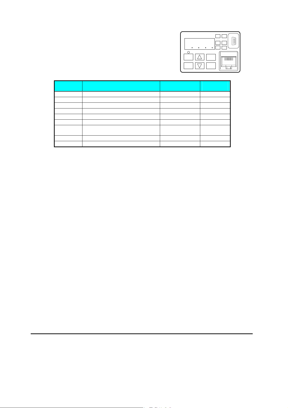
Keys, Modes, and Parameters
The purpose of the keypad is to provide a way to
change modes and parameters. The term function
applies to both monitoring modes and parameters.
These are all accessible through function codes that are
primary 4-character codes. The various functions are
separated into related groups identifiable by the
left-most character, as the table shows.
Function
Group
Type (Category) of Function Mode to Access
PRG LED
Indicator
“D” Monitoring functions Monitor
“F” Main profile parameters
Program
z
“A” Standard functions
Program
z
“B” Fine tuning functions
Program
z
“C” Intelligent terminal functions
Program
z
“H” Motor constant related functions
Program
z
“P” Pulse train input, torque, EzSQ, and
communication related functions
Program
z
“U” User selected parameters
Program
z
“E” Error codes
You can see from the following page how to monitor and/or program the parameters.
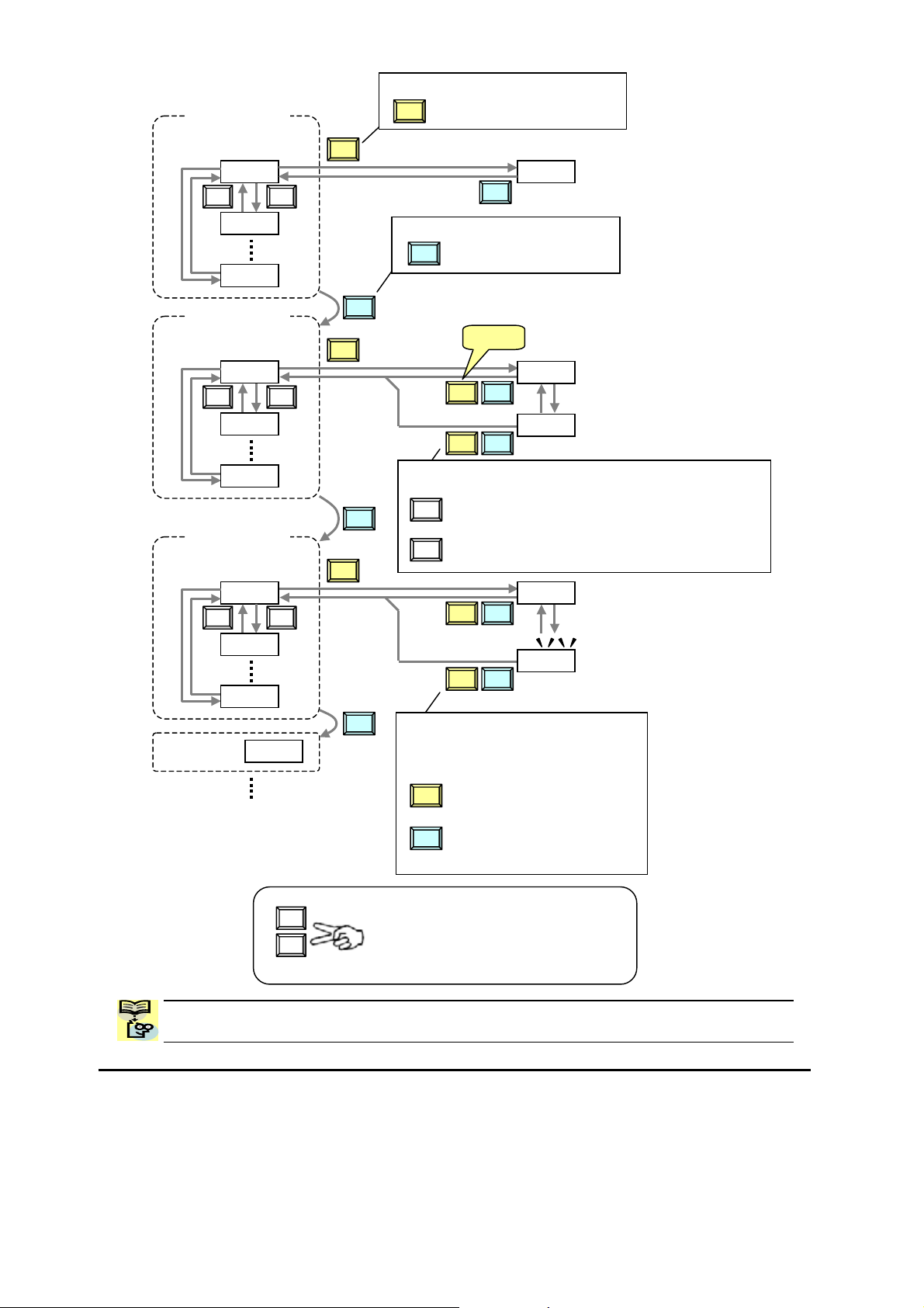
Keypad Navigation Map
The WJ200 Series inverter drives have many programmable functions and parameters.
Chapter 3 will cover these in detail, but you need to access just a few items to perform the
powerup test. The menu structure makes use of function codes and parameter codes to
allow programming and monitoring with only a 4-digit display and keys and LEDs. So, it is
important to become familiar with the basic navigation map of parameters and functions in
the diagram below. You may later use this map as a reference.
1
2
RUN
ESC
STOP/
RESET
SET
8888
RUN
Hz
A
PWR
ALM
PRG
16
NOTE: Pressing the [ESC] key will make the display go to the top of next function group,
regardless the display contents. (e.g. A021 Æ [ESC] Æ b001)
U
V
Press the both up and down key at the same
time in func. code or data display, then
single-digit edit mode will be enabled.
Refer to 2-34 for further information.
d001
V U
ESC
SET
Group "d"
Func. code display
0.00
d002
d104
F001
V U
Group "F"
Func. code display
F002
F004
50.00
50.01
SET
SET
ESC
SET
ESC
Save
A001
V U
Group "A"
Func. code display
A002
A165
00
01
SET
SET
ESC
SET
ESC
Data display
When data is changed, the display
starts blinking, which means that
new data has not been activated yet.
: Saves the data in EEPROM and
returns to func. code display.
: Cancels the data change and
returns to func. code display.
SET
ESC
Group "b"
b001
ESC
Func. code display
: Jumps to the next group
ESC
Func. code display
: Moves to data display
SET
ESC
ESC
Data display (F001 to F003)
Data does not blink because of real time synchronizing
: Saves the data in EEPROM
and returns to func. code display.
: Returns to func. code display without saving data.
SET
ESC
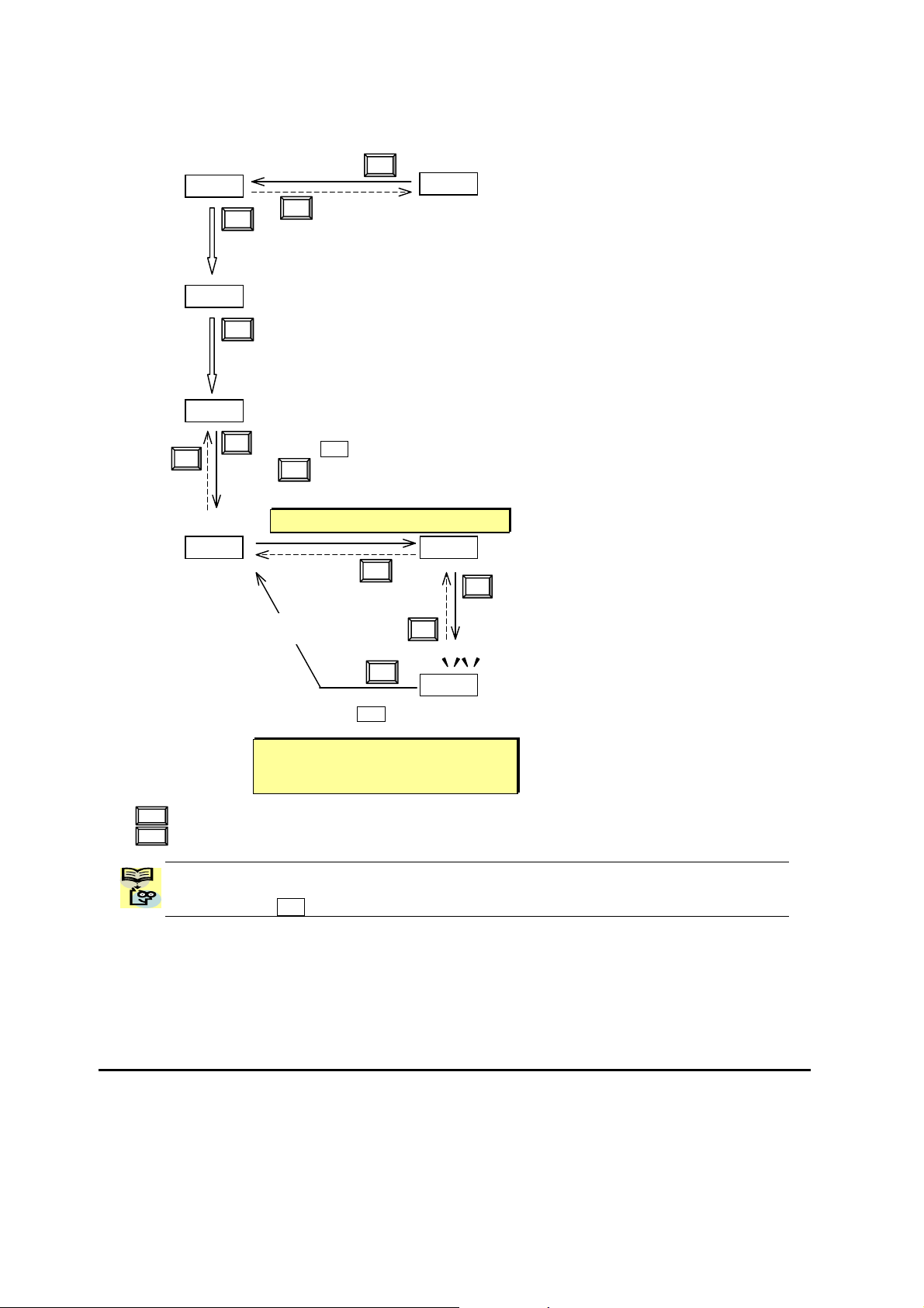
17
[Setting example]
After power ON, changing from 0.00 display to change the b083 (carrier frequency) data.
Function code dxxx are for monitor and not possible to change.
Function codes Fxxx other than F004 are reflected on the performance just after changing the data
(before pressing SET key), and there will be no blinking.
b001
b083
5.0
Display is solid lighting.
12.0
F001
d001
0.00
c Data of d001 will be shown on the
display after the first power ON
d Press [ESC] key to show
the function code
e Press [ESC] key to move
on to the function group F001
f Press [ESC] key twice to move
on to the function group b001.
g Press Up key to change increase
function code (b001
Æ b083)
h Press SET key to display the data of b083
i Press SET key to set
and save the data
When data is changed, the display
starts blinking, which means that new
data has not been activated yet.
ESC
U
V
SET
ESC
ESC
SET
ESC
U
V
:Fix and stores the data and moves back to the function code
:Cancels the change and moves back to the function code
SET
ESC
SET
i Press up key to increase the
data (5.0 Æ 12.0)

18
When a function
code is shown…
When a data is shown…
ESC key
Move on to the next
function group
Cancels the change and
moves back to the function
code
SET key
Move on to the data
display
Fix and stores the data and
moves back to the function
code
U key
Increase function
code
Increase data value
V key
Decrease function
code
Decrease data value
Note
Keep pressing for more than 1 second leads to d001 display, regardless the display situation. But note that
the display will circulates while keep pressing the [ESC] key because of the original function of the key.
(e.g. F001 Æ A001 Æ b001 Æ C001 Æ …Æ displays 50.00 after 1 second)
19
Connecting to PLCs and Other Devices
Hitachi inverters (drives) are useful in many types of applications. During installation, the
inverter keypad (or other programming device) will facilitate the initial configuration. After
installation, the inverter will generally receive its control commands through the control
logic connector or serial interface from another controlling device. In a simple application
such as single-conveyor speed control, a Run/Stop switch and potentiometer will give the
operator all the required control. In a sophisticated application, you may have a
programmable logic controller (PLC) as the system controller, with several connections to
the inverter.
It is not possible to cover all the possible types of application in this manual. It will be
necessary for you to know the electrical characteristics of the devices you want to connect
to the inverter. Then, this section and the following sections on I/O terminal functions can
help you quickly and safely connect those devices to the inverter.
CAUTION: It is possible to damage the inverter or other devices if your application
exceeds the maximum current or voltage characteristics of a connection point.
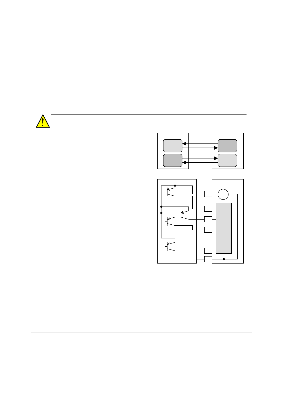
The connections between the inverter and
other devices rely on the electrical input/output
characteristics at both ends of each connection,
shown in the diagram to the right. The
inverter’s configurable inputs accept either a
sourcing or sinking output from an external
device (such as PLC). This chapter shows the
inverter’s internal electrical component(s) at
each I/O terminal. In some cases, you will
need to insert a power source in the interface
wiring.
In order to avoid equipment damage and get
your application running smoothly, we
recommend drawing a schematic of each
connection between the inverter and the other
device. Include the internal components of
each device in the schematic, so that it makes
a complete circuit loop.
After making the schematic, then:
1. Verify that the current and voltage for each
connection is within the operating limits of
each device.
2. Make sure that the logic sense (active high or active low) of any ON/OFF connection is
correct.
3. Check the zero and span (curve end points) for analog connections, and be sure the
scale factor from input to output is correct.
4. Understand what will happen at the system level if any particular device suddenly
loses power, or powers up after other devices.
Other device
Input
circuit
Output
circuit
WJ200 inverter
Input
circuit
Output
circuit
signal
return
signal
return
Other device WJ200 inverter
Input
circuits
P24
1
2
3
7
L
24V
+ -
GND
…
…
20
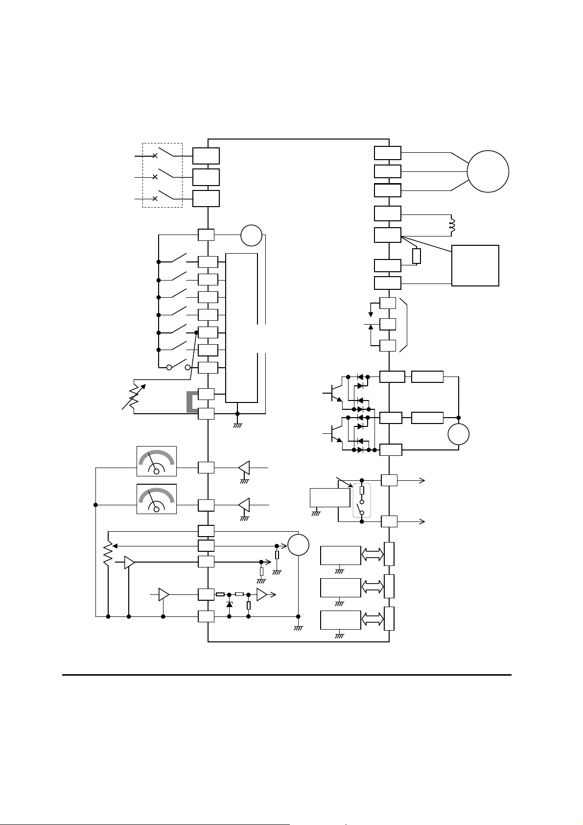
Example Wiring Diagram
The schematic diagram below provides a general example of logic connector wiring, in
addition to basic power and motor wiring converted in Chapter 2. The goal of this chapter
is to help you determine the proper connections for the various terminals shown below for
your application needs.
Breaker, MCCB
or GFI
Power source,
3-phase or
1-phase, per
inverter model
Input
circuits
24V
P24
+ -
1
2
3/GS1
4/GS2
5/PTC
Forward
Thermistor
Intelligent inputs,
7 terminals
GND for logic inputs
NOTE: For the wiring
of intelligent I/O and
analog inputs, be sure
to use twisted pair /
shielded cable. Attach
the shielded wire for
each signal to its
respective common
terminal at the inverter
end only.
Input impedance of
each intelligent input is
4.7k
[5] configurable as
discrete input or
thermistor input
AM
Meter
H
L
A
nalog reference
0~10VDC
4~20mA
GND for analog signals
WJ200
Moto
r
PD/+1
P/+
R
(
L1
)
S
(
L2
)
T
N
(
L3
)
U(T1)
V(T2)
W(T3)
N/-
DC reactor
(optional)
AL1
AL0
AL2
Relay contacts,
type 1 Form C
6
7/EB
EO
Meter
Pulse train input
24Vdc 32kHz max.
RB
Brake
resistor
(optional)
11/EDM
Load
Freq. arrival signal
Open collector output
Output circuit
GND for logic outputs
12
Load
+
CM2
L
L
+
O
OI
EA
A
pprx.10k
10Vdc
A
pprx.100
RS485
transceiver
RJ45 port
(Optional operator port)
USB
transceiver
USB (mini-B) port
(PC communication port)
USB power: Self power
L
L
Option port
controller
Option port connector
L
L
L
L
L
SP
SN
RS485
transceiver
Termination resistor (200
)
(Change by slide switch)
Serial communication port
(RS485/ModBus)
L
PLC
Short bar
(Source type)
NOTE: Common for
RS485 is “L”.
Braking
unit (optional)
21
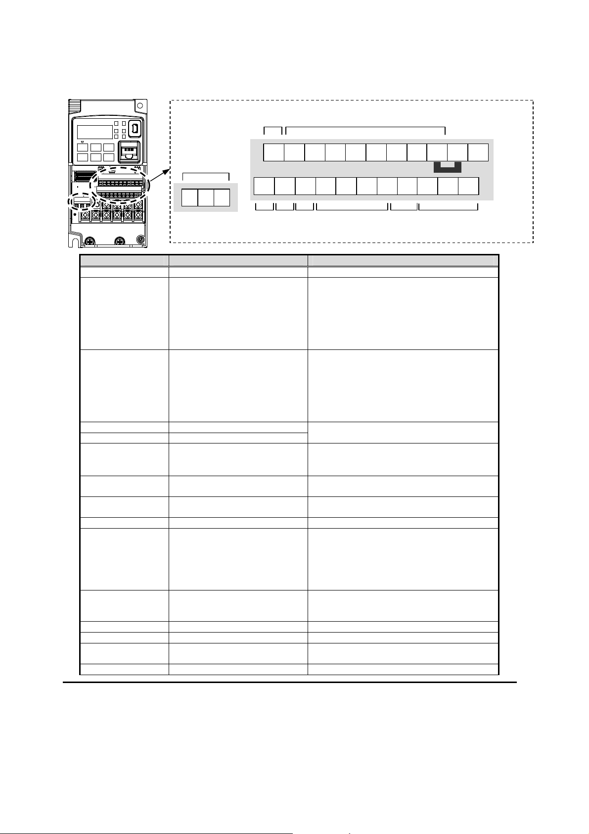
Control Logic Signal Specifications
The control logic connectors are located just behind the front housing cover. The relay
contacts are just to the left of the logic connectors. Connector labeling is shown below.
Terminal Name Description Ratings
P24 +24V for logic inputs 24VDC, 100mA. (do not short to terminal L)
PLC Intelligent input common Factory set: Source type for –FE and –FU
models (connecting [P24] to [1]~[7] turns
each input ON). To change to sink type,
remove the short bar between [PLC] and [L],
and connect it between [P24] and [L]. In this
case, connecting [L] to [1]~[7] makes each
input ON.
1
2
3/GS1
4/GS2
5/PTC
6
7/EB
Discrete logic inputs
(Terminal [3],[4],[5] and [7]
have dual function. See
following description and
related pages for the details.)
27VDC max. (use PLC or an external supply
referenced to terminal L)
GS1(3) Safe stop input GS1
GS2(4) Safe stop input GS2
Functionality is based on ISO13849-1
See appendix for the details.
PTC(5) Motor thermistor input Connect motor thermistor between PTC and
L terminal to detect the motor temperature.
Set 19 in C005.
EB(7) Pulse train input B 2kHz max.
Common is [PLC]
EA Pulse train input A 32kHz max.
Common is [L]
L (in upper row) *1 GND for logic inputs Sum of input [1]~[7] currents (return)
11/EDM Discrete logic outputs [11]
(Terminal [11] has dual
function. See following
description and related pages
for the details.)
50mA max. ON state current,
27 VDC max. OFF state voltage
Common is CM2
In case the EDM is selected, the functionality
is based on ISO13849-1
4VDC max. ON state voltage depression
12 Discrete logic outputs [12] 50mA max. ON state current,
27 VDC max. OFF state voltage
Common is CM2
CM2 GND for logic output 100 mA: [11], [12] current return
AM Analog voltage output 0~10VDC 2mA maximum
EO Pulse train output 10VDC 2mA maximum
32kHz maximum
L (in bottom row) *2 GND for analog signals Sum of [OI], [O], and [H] currents (return)
Analog
out
p
ut
Logic inputs
Logic
out
p
ut
Short bar
PLC
Analog
in
p
ut
Pulse
Train
in
p
ut
Pulse
Train
out
p
ut
RS485
comm.
RS485
comm.
P24 1 L 3
2
5
4
6
SN
7
12 11 AM
CM2
OI
L
H
O
EA
SP
EO
A
L2
A
L1
A
L0
Relay
contacts
22
Terminal Name Description Ratings
OI Analog current input 4 to 19.6 mA range, 20 mA nominal,
input impedance 100
O Analog voltage input 0 to 9.8 VDC range, 10 VDC nominal,
input impedance 10 k
H +10V analog reference 10VDC nominal, 10mA max.
SP, SN Serial communication terminal
For RS485 Modbus communication.
AL0, AL1, AL2 *3 Relay common contact 250VAC, 2.5A (R load) max.
250VAC, 0.2A (I load, P.F.=0.4) max.
100VAC, 10mA min.
30VDC, 3.0A (R load) max.
30VDC, 0.7A (I load, P.F.=0.4) max.
5VDC, 100mA min.
Note 1: The two terminals [L] are electrically connected together inside the inverter.
Note 2: We recommend using [L] logic GND (to the right) for logic input circuits and [L]
analog GND (to the left) for analog I/O circuits.
Note 3: Refer to page 39 for details of trip signals.
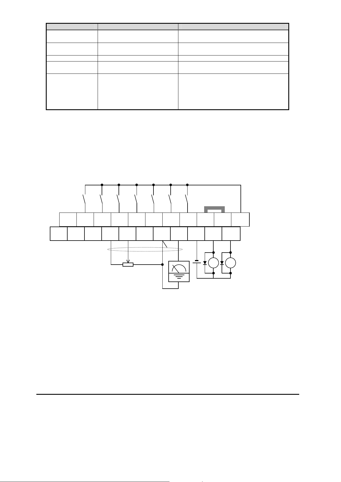
Wiring sample of control logic terminal (source logic)
Note: If relay is connected to intelligent output, install a diode across the relay coil
(reverse-biased) in order to suppress the turn-off spike.
SP EO EA H O OI L AM
CM2
12 11/EDM
Freq. meter
Variable resistor
for freq. setting
(
1k-2k
)
Short bar
(
source lo
g
ic
)
RY
SN 7/EB 6 5/PTC 4/GS2
3/GS1
1 L PLC
P24
RY
23
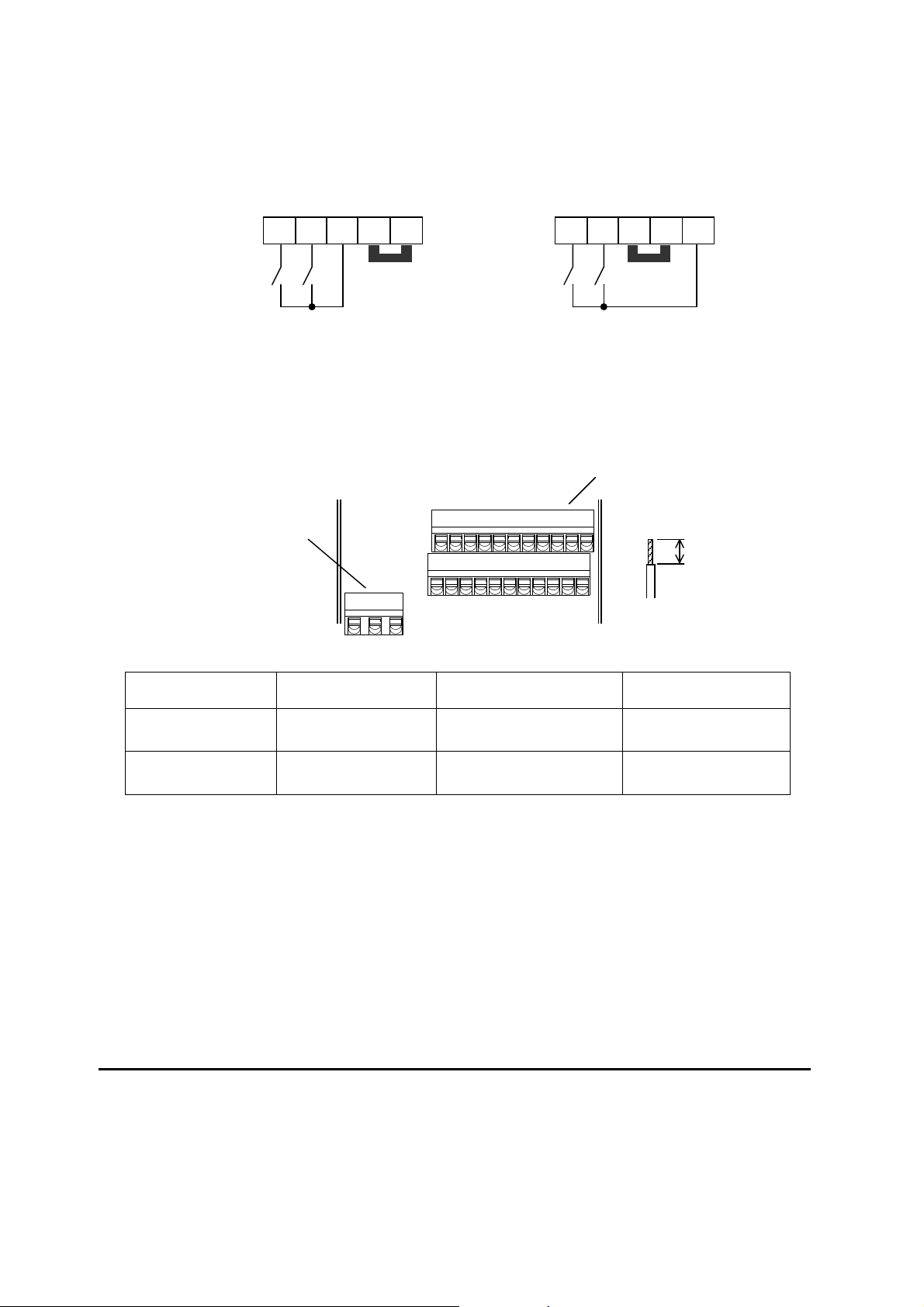
Sink/source logic of intelligent input terminals
Sink or source logic is switched by a short bar as below.
Wire size for control and relay terminals
Use wires within the specifications listed below. For safe wiring and reliabi li ty, it is
recommended to use ferrules, but if solid or stranded wire is used, stripping length should be
8mm.
Solid
mm
2
(AWG)
Stranded
mm
2
(AWG)
Ferrule
mm
2
(AWG)
Control logic
terminal
0.2 to 1.5
(AWG 24 to 16)
0.2 to 1.0
(AWG 24 to 17)
0.25 to 0.75
(AWG 24 to 18)
Relay terminal
0.2 to 1.5
(AWG 24 to 16)
0.2 to 1.0
(AWG 24 to 17)
0.25 to 0.75
(AWG 24 to 18)
Control lo
g
ic terminal
Relay output terminal
8mm
Short bar
PLC
P24
L 1 2
Sink lo
g
ic
Short bar
PLC
P24 L
1
2
Source lo
g
ic
24
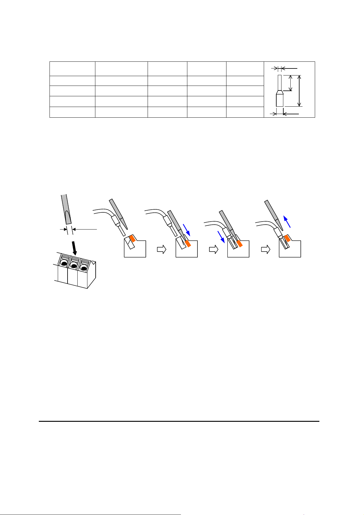
Recommendedferrule
For safe wiring and reliability, it is recommended to use following ferrules.
Wire size
mm
2
(AWG)
Model name of
ferrule *
L [mm] Φd [mm] ΦD [mm]
0.25 (24) AI 0.25-8YE 12.5 0.8 2.0
0.34 (22) AI 0.34-8TQ 12.5 0.8 2.0
0.5 (20) AI 0.5-8WH 14 1.1 2.5
0.75 (18) AI 0.75-8GY 14 1.3 2.8
* Supplier: Phoenix contact
Crimping pliers: CRIPMFOX UD 6-4 or CRIMPFOX ZA 3
Howtoconnect?
(1) Push down an orange actuating lever by a slotted screwdriver (width 2.5mm max.).
(2) Plug in the conductor.
(3) Pull out the screwdriver then the conductor is fixed.
8
L
Φd
ΦD
Push down an
orange actuating
lever.
Plug in the
conductor.
Pull out the
screwdriver to fix
the conductor.

25
Intelligent Terminal Listing
Intelligent Inputs
Use the following table to locate pages for intelligent input material in this chapter.
Input Function Summary Table
Symbol Code Function Name Page
FW 00 Forward Run/Stop
RV 01 Reverse Run/Stop
CF1 02 Multi-speed Select, Bit 0 (LSB)
CF2 03 Multi-speed Select, Bit 1
CF3 04 Multi-speed Select, Bit 2
CF4 05 Multi-speed Select, Bit 3 (MSB)
JG 06 Jogging
DB 07 External DC braking
SET 08 Set (select) 2nd Motor Data
2CH 09 2-stage Acceleration and Deceleration
FRS 11 Free-run Stop
EXT 12 External Trip
USP 13 Unattended Start Protection
CS 14 Commercial power source switchover
SFT 15 Software Lock
AT 16 Analog Input Voltage/Current Select
RS 18 Reset Inverter
PTC 19 PTC thermistor Thermal Protection
STA 20 Start (3-wire interface)
STP 21 Stop (3-wire interface)
F/R 22 FWD, REV (3-wire interface)
PID 23 PID Disable
PIDC 24 PID Reset
UP 27 Remote Control UP Function
DWN 28 Remote Control Down Function
UDC 29 Remote Control Data Clearing
OPE 31 Operator Control
SF1~SF7 32~38 Multi-speed Select,Bit operation Bit 1~7
OLR 39 Overload Restriction Source Changeover
TL 40 Torque Limit Selection
TRQ1 41 Torque limit switch 1
TRQ2 42 Torque limit switch 2
BOK 44 Brake confirmation
LAC 46 LAD cancellation
PCLR 47 Pulse counter clear
ADD 50 ADD frequency enable
F-TM 51 Force Terminal Mode
ATR 52 Permission for torque command input
KHC 53 Clear watt-hour data
MI1~MI7 56~62 General purpose input (1)~(7)
AHD 65 Analog command hold
CP1~CP3 66~68 Multistage-position switch (1)~(3)
ORL 69 Limit signal of zero-return
ORG 70 Trigger signal of zero-return
SPD 73 Speed/position changeover
GS1 77 STO1 input (Safety related signal)
GS2 78 STO2 input (Safety related signal)
485 81 Starting communication signal
PRG 82 Executing EzSQ program
HLD 83 Retain output frequency
ROK 84 Permission of Run command
EB 85 Rotation direction detection (phase B)

26
Use the following table to locate pages for intelligent input material in this chapter.
Input Function Summary Table
Symbol Code Function Name Page
DISP 86 Display limitation
NO 255 No assign
Intelligent Outputs
Use the following table to locate pages for intelligent output material in this chapter.
Input Function Summary Table
Symbol Code Function Name Page
RUN 00 Run Signal
FA1 01 Frequency Arrival Type 1–Constant Speed
FA2 02 Frequency Arrival Type 2–Over frequency
OL 03 Overload Advance Notice Signal
OD 04 PID Deviation error signal
AL 05 Alarm Signal
FA3 06 Frequency Arrival Type 3–Set frequency
OTQ 07 Over/under Torque Threshold
UV 09 Undervoltage
TRQ 10 Torque Limited Signal
RNT 11 Run Time Expired
ONT 12 Power ON time Expired
THM 13 Thermal Warning
BRK 19 Brake Release Signal
BER 20 Brake Error Signal
ZS 21 Zero Hz Speed Detection Signal
DSE 22 Speed Deviation Excessive
POK 23 Positioning Completion
FA4 24 Frequency Arrival Type 4–Over frequency
FA5 25 Frequency Arrival Type 5–Set frequency
OL2 26 Overload Advance Notice Signal 2
ODc 27 Analog Voltage Input Disconnect Detection
OIDc 28 Analog Voltage Output Disconnect Detection
FBV 31 PID Second Stage Output
NDc 32 Network Disconnect Detection
LOG1~3 33~35 Logic Output Function 1~3
WAC 39 Capacitor Life Warning Signal
WAF 40 Cooling Fan Warning Signal
FR 41 Starting Contact Signal
OHF 42 Heat Sink Overheat Warning
LOC 43 Low load detection
MO1~3 44~46 General Output 1~3
IRDY 50 Inverter Ready Signal
FWR 51 Forward Operation
RVR 52 Reverse Operation
MJA 53 Major Failure Signal
WCO 54 Window Comparator for Analog Voltage Input
WCOI 55 Window Comparator for Analog Current Input
FREF 58 Frequency Command Source
REF 59 Run Command Source
SETM 60 2
nd
Motor in operation
EDM 62 STO (Safe Torque Off) Performance Monitor
(Output terminal 11 only)
OP 63 Option control signal
no 255 Not used
27
Using Intelligent Input Terminals
Terminals [1], [2], [3], [4], [5], [6] and [7] are identical, programmable inputs for general use.
The input circuits can use the inverter’s internal (isolated) +24V field supply or an external
power supply. This section describes input circuits operation and how to connect them
properly to switches or transistor outputs on field devices.
The WJ200 inverter features selectable sinking or sourcing inputs. These terms refer to the
connection to the external switching device–it either sinks current (from the input to GND)
or sources current (from a power source) into the input. Note that the sink/source naming
convention may be different in your particular country or industry. In any case, just follow
the wiring diagrams in this section for your application.
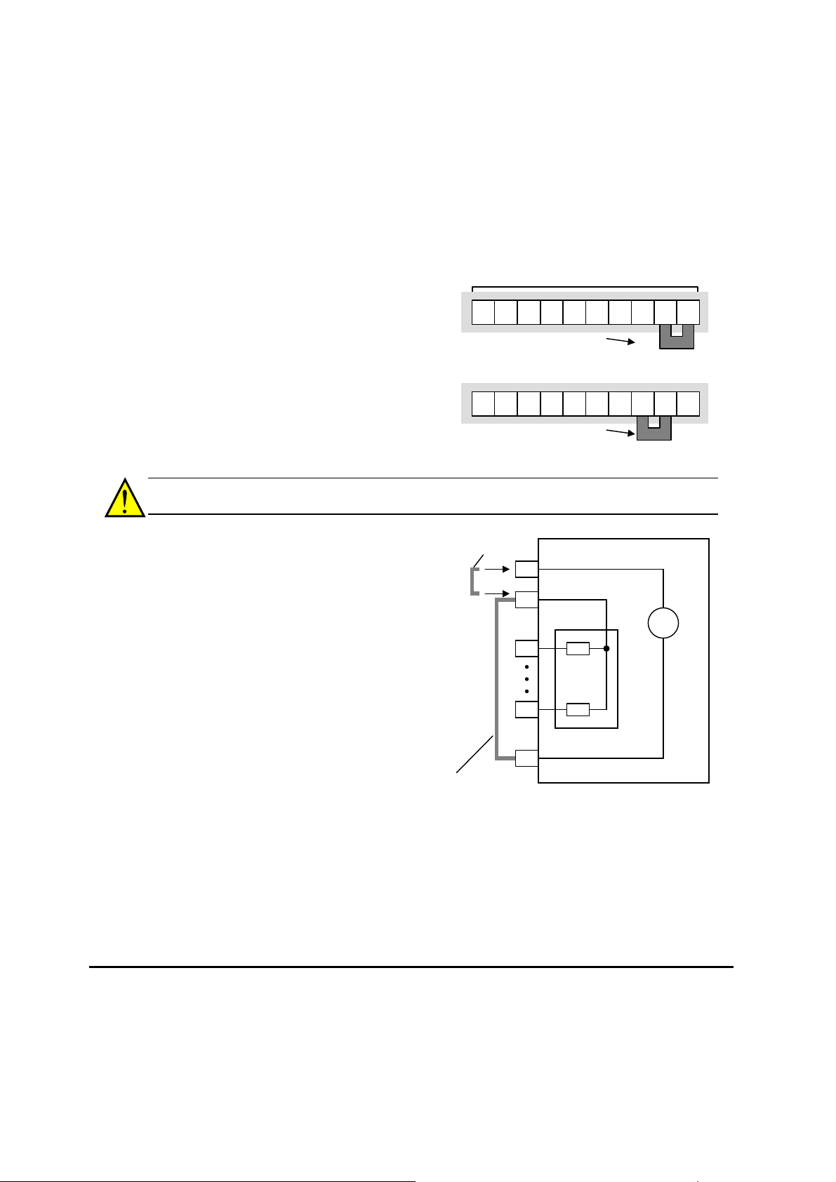
The inverter has a short bar (jumper) for
configuring the choice of sinking or sourcing
inputs. To access it, you must remove the
front cover of the inverter housing. In the
figure to the top right, the short bar is shown
as attached to the logic terminal block
(connector). For EU and US version (suffix
–xFE, and –xFU), it is originally located as
source type logic. If you need to change to
the sink type connection, remove the short
bar and connect it as shown in the figure at
the bottom right.
CAUTION: Be sure to turn OFF power to the inverter before changing the short circuit bar
position. Otherwise, damage to the inverter circuitry may occur.
[PLC] Terminal Wiring – The [PLC]
terminal (Programmable Logic Control
terminal) is named to include various
devices that can connect to the inverter’s
logic inputs. In the figure to the right, note
the [PLC] terminal and the short bar
(jumper). Locating the short bar between
[PLC] and [L] sets the input logic source
type, which is the default setting for EU
and US versions. In this case, you
connect input terminal to [P24] to make it
active. If instead you locate the short bar
between [PLC] and [P24], the input logic
will be sink type. In this case, you
connect the input terminal to [L] to make
it active.
The wiring diagram on the following pages show the four combinations of using sourcing or
sinking inputs, and using the internal or an external DC supply.
WJ200 inverter
P24
1
7
L
24V
PLC
Input
circuits
+
-
Logic GND
Input common
Short bar for
sink logic
Short bar for
source logic
Lo
g
ic in
p
uts
5 4 3 2 1 L
PLC
P24
Source lo
g
ic connection
Short ba
r
7 6
5 4 3 2 1 L
PLC
P24
Sink lo
g
ic connection
Short ba
r
7 6
 Loading...