


VME578LEAU
SERVICE MANUAL
MANUEL D'ENTRETIEN
WARTUNGSHANDBUCH
CAUTION:
Before servicing this chassis, it is important that the service technician read the “Safety
Precautions” and “Product Safety Notices” in this service manual.
SM7103
VMH775LE
VME578LEAU
VME578LESW
VME575LE
AC Adapter
VMACE5E
VMACE5EAU
Data contained within this Service
manual is subject to alteration for
improvement.
ATTENTION:
Avant d’effectuer l’entretien du châassis, le technicien doit lire les «Précautions de sécurité»
et les «Notices de sécurité du produit» présentés dans le présent manuel.
VORSICHT:
Vor Öffnen des Gehäuses hat der Service-Ingenieur die „Sicherheitshinweise“ und „Hinweise
zur Produktsicherheit“ in diesem Wartungshandbuch zu lesen.
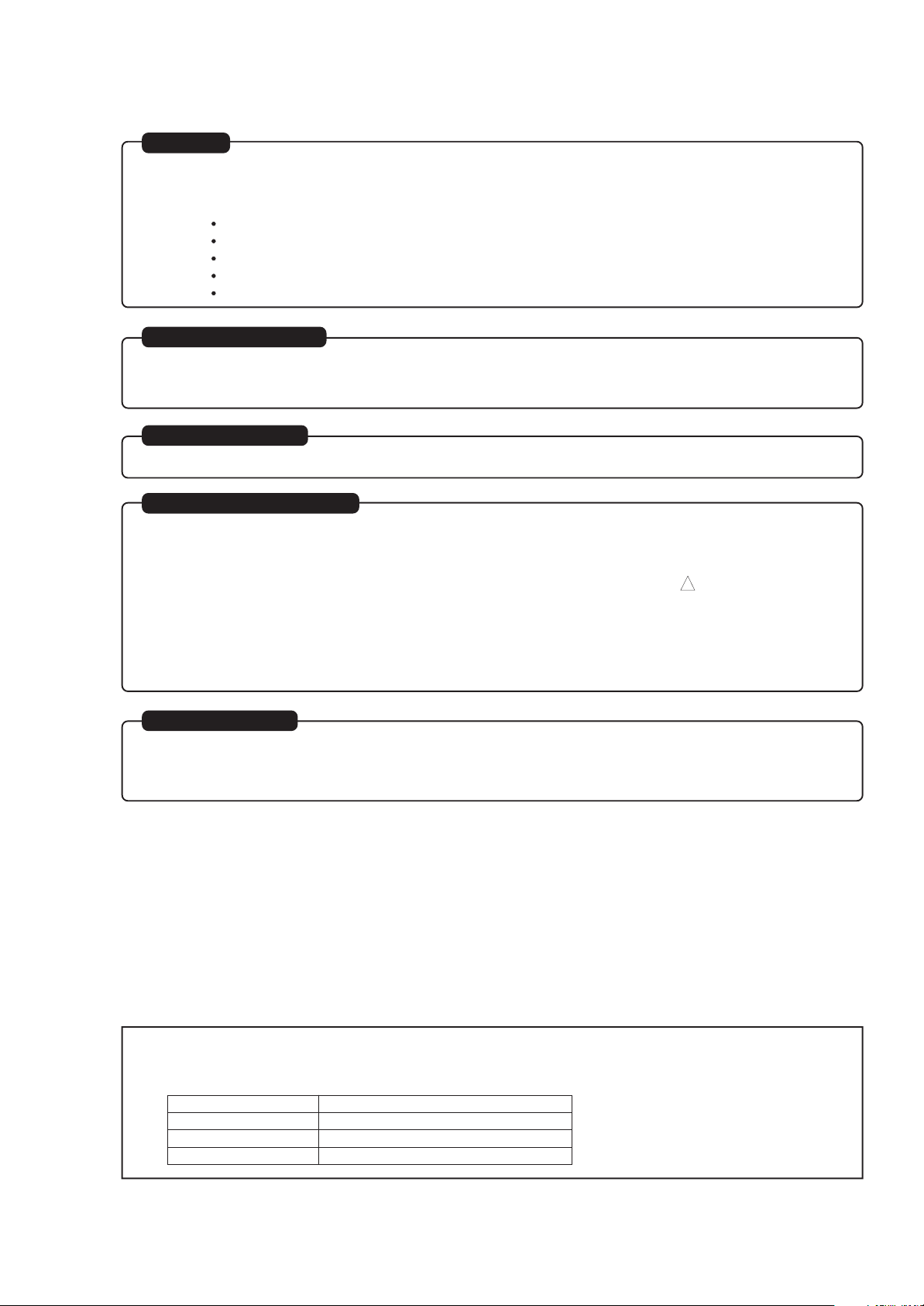
When Servicing the Mechanism:
This camera/recorder uses a UH mechanism.
When servicing the UH mechanism, refer to the
following service manuals:
Item Manuals to be referred to
Disassembly UH Mechanism (No. 6811E)
Mechanical UH Mechanism Supplement
Adjustment (No. 6811E-1)
Maintenance/
Inspection UH mechanism (No. 6811E)
Procedure
Exploded View Chapter 4 in this manual
Les données fournies dans le présent
manuel d’entretien peuvent faire l’objet
de modifications en vue de perfectionner
le produit.
Die in diesem Wartungshandbuch
enthaltenen Spezifikationen können sich
zwecks Verbesserungen ändern.
SPECIFICATIONS AND PARTS ARE SUBJECT TO CHANGE FOR IMPROVEMENT
8mm VIDEO CAMERA/RECORDER
FEBRUARY 2001

CONTENTS
CHAPTER 1 GENERAL INFORMATION
SPECIFICATIONS
COMPARISON OF FEATURES
COMPARISON OF MAIN CONTROL ICs
JIGS AND TAPES FOR SERVICE
HOW TO USE THE EXTENSION CABLE AND JIG..1-6
SERVICE POSITION
SERVICE MANUAL ABBREVIATION LIST
EXTRACT FROM THE INSTRUCTION MANUAL
IDENTIFYING CONTROLS
DATE/TIME SETTING
CHARGING THE BATTERY
ITEMS SELECTABLE WITH MENU DISPLAY
.....................................................
................................
.................
............................
.................................................
...............
.....
..................................
..........................................
................................
....
1-1
1-2
1-4
1-5
1-6
1-7
1-9
1-9
1-10
1-11
1-12
CHAPTER 2 DISASSEMBLY
1. BEFORE STARTING DISASSEMBLY
1.1 Disassembly Procedure
2. CASES AND CIRCUIT BOARDS REMOVAL
2.1 Jack Cover, Front Cover Assembly,
Lens Cover,
2.2 PSW Circuit Board, Microphone Unit,
DC Light, Front Cover
2.3 LCD Case-U, LCD Block, Cassette Lid,
Top Cover
2.4 L-Case Assembly, R-Case Assembly
2.5 Electronic Viewfinder (EVF) Assembly,
Speaker, CON Circuit Board, Fulcrum,
L-Case
2.6 Camera Chassis Assembly [Lens Frame,
Lens, SE Circuit Board, CCD Sensor],
VCR Chassis Assembly, Jack Unit, Rear
Cover, Power Terminal Unit
2.7 VCA Circuit Board, Mechanism Frame,
UH Mechanism
2.8 Hand Strap, TW/PW Switch, R-Case
2.9 LCD Circuit Board, Back light,
LCD Module, LCD Case-B
2.10 EVF Case-R, EVF Case-L, Eye Piece
3. HOW TO OPERATE THE
MECHANISM MANUALLY
..................................................
....................................................
..........................................................
.............................................
...............................
..................................
................................
.................
......
..........
.........................
..........
...........................
.........
2-1
2-1
2-2
2-2
2-2
2-3
2-4
2-5
2-6
2-7
2-7
2-8
2-8
2-9
CHAPTER 3 ELECTRIC CIRCUIT
ADJUSTMENT
1. CONNECTION FOR ADJUSTMENT
1.1 Before Starting Adjustment
2. CAMERA SECTION ADJUSTMENT
2.1 Test Equipment Necessary for
Adjustment
2.2 List of Charts for Camera Adjustment
2.3 Adjustment Conditions
2.4 Preset Positions of Switches and
Controls During Adjustment
...................................................
.................................
...................
..........................
....................
..........
.........................
3-1
3-1
3-2
3-2
3-2
3-2
3-2
2.5 Check After Replacing Major Components
in the Camera Section
2.6 Adjustment Procedure
2.6.1 Connections for Adjustment
2.6.2 How to Start the MAP
2.6.3 Initial Setting by Model
2.6.4 Digital Adjustment Procedure
(1) Auto Iris Contorl Adjustment
(2) White Balance Adjustment
(3) Chroma Gain Adjustment
2.6.5 Autofocus Adjustment Procedure
(1) Zoom Trace Adjustment
(2) AF Noise Level Adjustment
2.6.6 Stabilizer Adjustment Procedure
2.6.7 Spot Noise Adjustment
2.7 Color LCD Monitor Adjustment
2.7.1 Adjustment Procedure
(1) Flicker Adjustment
3. VCR SECTION ADJUSTMENT
3.1 Test Equipment and Alignment Tapes
Necessary for Adjustment
3.2 Adjustment Conditions
3.3 Preset Positions of Switches and
Controls During Adjustment
3.4 Check After Replacing Major Components
in the VCR Section
3.5 System Control/Servo Circuits
Adjustment
(1) Power Shut Off Level (ODC: Over
(2) Head Switching Point Adjustment
4. ERROR MESSAGES
4.1 Digital Adjustment
4.2 Autofocus Adjustment
4.3 Stabilizer Adjustment
4.4 Spot Noise Adjustment
4.5 VCR Adjustment
5. TROUBLESHOOTING OF AUTOFOCUS
(1) No Zoom and Focus Operation
(2) No Focus Lens Operation
(3) No Zoom Operation
(4) No Autofocus Operation
(5) Subject is Greatly Out-of-Focus
When Zoomed
...................................................
Discharge Control) Adjustment
.................................
.................................
..................
............................
..........................
.................
....................
......................
........................
...................
..........................
....................
...........................
.................................
............................
............................
.................................
.........................
.......................................
...........................................
........................................
..................................
...................................
................................
..........................................
...................
............................
.....................................
...............................
.............................................
CHAPTER 4 EXPLODED VIEW
CABINET (1)
CABINET (2)
UH MECHANISM
ACCESSORIES
..............................................................
..............................................................
.......................................................
.........................................................
...............
.........
...........
.............
.........
............
3-3
3-3
3-3
3-4
3-4
3-5
3-5
3-5
3-6
3-7
3-7
3-7
3-8
3-8
3-9
3-9
3-9
3-10
3-10
3-10
3-10
3-10
3-10
3-11
3-11
3-12
3-12
3-13
3-13
3-13
3-14
3-15
3-15
3-17
3-18
3-19
3-21
4-1
4-2
4-3
4-4
CONTENTS-1

CHAPTER 5 REPLACEMENT
P ARTS LIST
1. MECHANICAL PARTS LIST
2. ELECTRICAL PARTS LIST
CHAPTER 6
SCHEMATIC, CIRCUIT BOARD
................................
.................................
AND BLOCK DIAGRAMS/
MICROPROCESSOR PIN
FUNCTION TABLE
INTERNAL WIRING DIAGRAM
SENSOR/GYRO [SE]
CAMERA PROCESS [VCA]
SYSTEM CONTROL [VCA]
MECHA. STATE SWITCH/
MECHA. SENSOR
POWER SW [PSW]
SERVO [VCA]
AUDIO -STEREO- [VCA]
AUDIO -MONAURAL- [VCA]
REGULATOR [VCA]
VIDEO PROCESS [VCA]
CHARGE [VCA]
CONTROL [CON]
LCD DRIVE [LCD]
...................................
....................................
......................................
...............................................
.....................................
............................................
.........................................
........................................
................................
Schematic / Circuit
..........................
..........................
..............................
........................
..............................
5-1
5-2
6-1
Board
6-3 / 6-33,35
6-5 / 6-37,43
6-7 / 6-37,43
6-9 / ----6-10/ 6-33,35
6-11/ 6-37,43
6-13/ 6-37,43
6-15/ 6-37,43
6-17/ 6-37,43
6-21/ 6-37,43
6-24/ 6-37,43
6-25/ 6-33,35
6-27/ 6-31
CHAPTER 7 APPENDIX
1. SELF-DIAGNOSTIC FUNCTION
1.1 Overview
1.2 Details of Display/
Detection and Applications
1.3 Setting Procedure and
Details of Diagnosis
1.3.1 Occasional Defect Self-Diagnostic
1.3.2 Mechanical Block Self-Diagnostic
2. DEMONSTRATION (DEMO) MODE
2.1 Setting the Demo Mode
2.2 Exiting the Demo Mode
2.3 Contents of Demonstration
......................................................
Function (Mode A)
Function (Mode B)
.........................
..........................
.....................................
.................................
.................................
...............................
................................
..........................
CHAPTER 8 AC ADAPTER
VM-ACE5E
................................................................
.................
7-1
7-1
7-2
7-3
7-3
7-4
7-6
7-6
7-6
7-6
8-1
WAVEFORM
SENSOR/GYRO
SYSTEM CONTROL
SERVO
VIDEO PROCESS
BLOCK DIAGRAMS
1. OVERALL BLOCK DIAGRAM
2. MAIN CONTROL BLOCK DIAGRAM
3. SERVO BLOCK DIAGRAM
4. CAMERA & VIDEO PROCESS
5. AUDIO -STEREO- BLOCK DIAGRAM
6. AUDIO -MONAURAL- BLOCK DIAGRAM
7. POWER BLOCK DIAGRAM
MICROPROCESSOR PIN FUNCTION TABLE
1. Digital Microprocessor (IC1104: D-µP)
2. System Control Microprocessor
................................................................
BLOCK DIAGRAM
(IC0901: S-µP)
.................................................
...........................................
..............................................
......................
..........................
.......................................
.........................
.............................................
...........
.........
........
6-3
6-9
6-11
6-19
6-49
6-51
6-53
6-55
6-57
...
6-59
6-61
6-63
6-65
CONTENTS-2
CAUTION
Lithium battery; danger of explosion if battery is incorrectly replaced. Replace only with the same or equivalent type
recommended by the equipment manufacturer. Discard used batteries according to manufacuturer's instructions.
When replacing the lithium battery it is important to use the same type and connect it correctly.
WARNING:
Lithium batteries contain dangerous chemicals.
Handle and dispose of with great care.
Do not throw in a fire.
Do not short circuit it.
For disposal place in a plastic bag and put in waste bin.
CAUTION (COLOR LCD)
LCD display; the liquid crystal display (LCD) panel is mode by highly precise technology.
More than 99.99% of its picture elements (pixels) are effective, but some (less than 0.01%) may appear as colored
bright dots. This mode not indicate a fault as the LCD panel stretches the limits of current technology.
CAUTION (CRT EVF)
Be careful of the section painted in white on the electronic viewfinder circuit board as it generates a high voltage.
PRODUCT SAFETY NOTICE
Many electrical and mechanical parts have special safety-related characteristics. These are often not evident from
visual inspection nor can the protection afforded by them necessarily be obtained by using replacement components rated
for a higher voltage, wattage, etc. Replacement parts which have these special safety characteristics are identified in this
Service Manual. Electrical components having such features are identified by marking with a on the schematics and the
parts list in this Service Manual. The use of a substitute replacement component which does not have the same safety
characteristics as the HITACHI recommended replacement one, shown in the parts list in this Service Manual, may create
shock, fire, or other hazards. Product safety is continuously under review and new instructions are issued from time to time.
For the latest information, always consult the current HITACHI Service Manual. A subscription to, or additional copies for,
HITACHI Service Manual may be obtained at a nominal charge from HITACHI SALES CORPORATION.
!
X-RAY RADIATION
The primary source of X-ray radiation in this viewfinder is the picture tube. The tube used in this viewfinder is specially
constructed to limit X-ray radiation emission. For continued X-ray radiation protection, the replacement tube must be
same type as the original, Hitachi approved one.
How to discriminate the "TYPE" identifications in the manual
The parts and circuits are identified by "TYPE" in this manual to discriminate the differences between models. The
TYPE numbers are the same as the model numbers. The table below shows how to read the type identifications.
TYPE identification Model name
TYPE 775 VM-H775LE
TYPE 578 VM-E578LE(AU)/E578LE(SW)
TYPE 575 VM-E575LE
CAUTION-1

Notes When Using Service Manual
The following shows the contents to be noted when using service manual:
1. Value units used in parts list
Certain symbols are indicated below for value units of
resistors, capacitors and coils in parts list. When you read
them note the following regular indications:
Parts
Resistor
Capacitor
Coil
Indication in list Regular indication
...........................................
KOHM
................................................
UF
................................................
PF
................................................
UH
...............................................
MH
2. Values in schematic diagrams
The values, dielectric strength (power capacitance) and
tolerances of the resistors (excluding variable resistors)
and capacitors are indicated in the schematic diagrams
using abbreviations.
[Resistors]
Item
Value
Tolerance
Power
capacitance
Indication
No indication
................................................
K
...............................................
M
No indication
(All tolerances other than ±5% are
indicated in schematic diagrams)
No indication
(1/16W for leadless resistors without
indication)
All capacitances other than the above
are indicated in schematic diagrams.
...................................
.............................
............................
±5%
1/8W
k
M
k
µF
pF
µH
mH
3. Identifications of sides A/B in
circuit board diagrams
1) Board having a pattern on one side and parts on both
sides.
Side A: Shows discrete parts, viewed from the pattern
side.
Side B: Shows leadless parts, viewed from the
pattern side.
2) Board having patterns on both sides and parts on
both sides.
Side A: Shows parts and patterns which can be seen
when the case is opened.
Side B: Shows parts and the pattern on the back of
side A.
4. Table for indexing locations of parts
This table shows locations of each part on circuit board
diagrams. The locations are indicated using the guide
scales on the external lines of diagrams.
1) One diagram indicated for each board
Symbol
No.
IC
IC1201
Circuit No.
2) Two diagrams indicated for each board
Parts
Location
Type of part
2 A
Zone "A" on board diagram
Zone "2" on board diagram
[Capacitors]
Item
Value
Dielectric
strength
[Coils]
Item
Value
CAUTION-2
Indication
No indication
................................................
P
No indication
(All dielectric strengths other than 50V
are indicated in schematic diagrams)
Indication
................................................
µ
...............................................
m
.................................
..............................
µF
pF
50V
µH
mH
Symbol
No.
IC
IC1201
Circuit No.
Parts
Location
A - 2 A
A: Shows side A
B: Shows side B
Type of
part
Zone "A" on board
diagram
Zone "2" on board
diagram

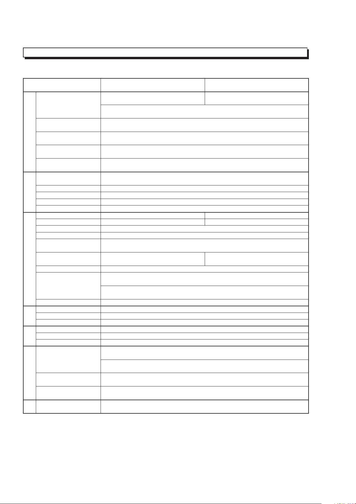
CHAPTER 1 GENERAL INFORMATION
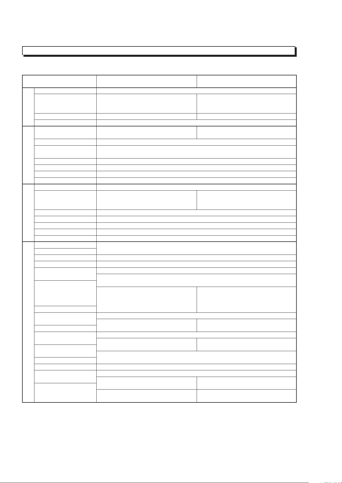
SPECIFICATIONS
General Specifications
Power requirements 7.2V DC
Power consumption VM-H775LE:
3.6W (when recording/LCD monitor OFF)
4.1W (when recording/LCD monitor ON)
VM-E578LE(AU)/E578LE(SW):
3.4W (when recording/LCD monitor OFF)
3.8W (when recording/LCD monitor ON)
VM-E575LE:
3.4W (when recording/LCD monitor OFF)
3.8W (when recording/LCD monitor ON)
Operating temperature 0°C to 40°C
Operating humidity < 80 %
Storage temperature -20°C to 60°C
Dimensions 111.5 (W) mm × 111.5 (H) mm × 200 (D) mm
Weight Approx. 836 g
Video Recorder Specifications
Format 8 mm
Record/playback system Two video record/playback heads
Video signal PAL colour & CCIR monochrome signals 625 lines
Tape speed SP: 20.05 mm/s
Video output 1.0 Vp-p, 75 ohm
Audio output -8 dBs, less than 1k ohm
Fast forward/rewind time Approx. 6 minutes with P5-90 cassette
Camera Specifications
Scanning 625 lines/50 fields/25 frames
Required minimum illumination VM-H775LE: 0.5 lx
VM-E578LE(AU)/E578LE(SW): 0.1 lx
VM-E575LE: 0.3 lx
Camera device 1/4 inch C.C.D.
Lens F1.6 to 3.8 (4 to 88 mm) 22:1 power zoom lens with auto focus
and auto iris functions
Lens diameter 46 mm
1 - 1
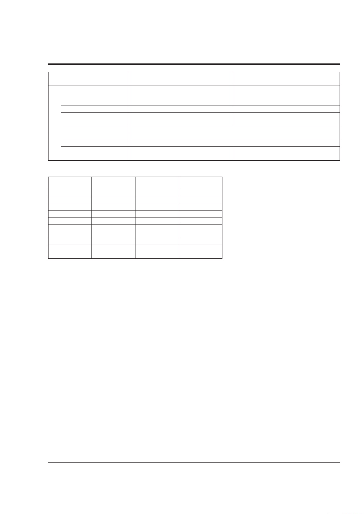
COMPARISON OF FEATURES
Note: Destinations normally added at the end of model names, (AU), (SW), (UK), etc. are omitted in this table.
ITEM
Power Requirements
Power Consumption
(when recording/LCD
monitor ON)
GENERAL
Dimensions (W × H × D )
Weight
Format
Record/Playback System
Video Signal
VIDEO
Tape Speed
F.F/Rew Time
Head Weel
Basic Chassis Type
Scanning
Required Minimum
Illumination
Camera Device
Lens Diameter
CAMERA
Zoom Ratio
Aperture
Zoom Speed
Electronic Viewfinder (EVF)
Electrical Zoom Function
INST. ZOOM Function
Autofocus System
Program AE
(Shutter Speed)
Selective Program AE
AV Input Function
S-Connector Output
AV Dubbing
FEATURES
Audio System &
Microphone
Multi Playback
(PAL 60 Conversion)
Digital Effect & Fade
Date Search
Tape Analyzer ATRS
TAPE+ Function
VM-H775LE/E578LE/E575LE
7.2 V DC
VM-H775LE: 4.1 W
VM-E578LE/E575LE: 3.8 W
111.5 mm × 111.5 mm × 200 mm
Approx. 836 g
VM-H775LE: 8 mm (Hi-8)
VM-E578LE/E575LE: 8 mm
Two video record/playback heads
PAL colour & CCIR monochrome signal
625 line
SP: 20.05 mm/s
Less than 6 minutes with P5-90 cassette
40 mm
UH
625 lines/50 fields/25 frame
VM-H775LE: 0.5 lx
VM-E578LE:0.1 lx
VM-E575LE:0.3 lx
1/4 inch C.C.D
46 mm
22 : 1 (4.0 - 88.0 mm)
F1.6 - 3.8
Adjustable speed
CRT (Black & White)
Yes [× 500 (22 × 22)]
No
Video AF System
Yes
(Program AE only)
VM-H775LE/E575LE: Yes
(AUTO, SPORTS, PORTRAIT,
SPOTLIGHT, GAIN UP)
VM-E578LE: No
No
VM-H775LE: Yes
VM-E578LE/E575LE: No
Yes (Using the remote controller)
VM-H775LE: Stereo
VM-E578LE/E575LE: Monaural
Yes (Selective)
Yse
Yes
VM-H775LE: Yes
VM-E578LE/E575LE: No
VM-H775LE: Yes
VM-E578LE/E575LE: No
VM-H765LE/E568LE/E565LE
VM-H765LE: 4.1 W
VM-E568LE/E565LE: 3.8 W
111.5 mm × 111.5 mm × 202 mm
VM-H765LE: 8 mm (Hi-8)
VM-E568/E565LE: 8 mm
VM-H765LE: 0.5 lx
VM-E568LE/E565LE: 0.3 lx
VM-H765LE/E565LE: Yes
(AUTO, SPORTS, PORTRAIT,
SPOTLIGHT, GAIN UP)
VM-E568LE: No
VM-H765LE: Yes
VM-E568LE/E565LE: No
VM-H765LE: Stereo
VM-E568LE/E565LE: Monaural
VM-H765LE: Yes
VM-E568LE/E565LE: No
VM-H765LE: Yes
VM-E568LE/E565LE: No
1 - 2
ITEM
VM-H775LE/E578LE/E575LE
VM-H765LE/E568LE/E565LE
Electronic Image Stabilizer
(EIS)
[Picture element system]
LCD Display
Internal DC Light
FEATURES
Internal Battery Charge
AC Adapter/Charger
Battery Pack
Remote Controller
ACCE-
SSORY
System
Audio
Built-in DC light
EIS function
Tape +
Programme AE
Remote control
Microphone
jack
VM-H775LE
Hi-8
Stereo
Yes
Yes
Yes
Auto/Mode
select
Provided
Yes
VM-H775LE/E575LE: Yes
VM-E578LE: No
Yes (2.5 inch)
VM-H775LE/E578LE: Yes
VM-E575LE: No
Yes
VM-ACE5E
VM-BPL13
VM-H775LE/E575LE: VM-RME611A
VM-E578LE: Not provided
VM-E578LE(AU)
VM-E578LE(SW)
Normal 8
Monaural
Yes
No
No
Auto
Not provided
No
VM-E575LE
Normal 8
Monaural
No
Yes
No
Auto/Mode
select
Provided
Yes
VM-H765LE/E565LE: Yes
VM-E568LE: No
VM-H765LE: Yes
VM-E568LE/E565LE: No
VM-H765LE/E565LE: VM-RME611A
VM-E568LE: Not provided
Memo
1 - 3
COMPARISON OF MAIN CONTROL ICs
Note: Destinations normally added at the end of model names, (AU), (SW), (UK), etc. are omitted in this table.
ITEM
CCD Sensor
V-Move (Vertical Gyro)
H-Move (Horizontal Gyro)
Gyro Amp
CCD SENSOR & GYRO
Sensor Drive (Drive Pulse
Generator)
Video DSP
(Digital Process)
CDS/AGC & A/D Conv.
Video Head Switch
VIDEO
Video Amp
PROCESS
RGB Amp
Digital µP (D-µP)
EEPROM
D/A Conv.
F Det./Iris Drive
Zoom Motor/Focus Motor
Driver
System Control µP (S-µP)
Back-up Det.
Character Gen.
SYSTEM CONTROL
CAMERA CONTROL &
IR Receiver
Cylinder Motor Drive
Capstan Motor Drive
SERVO
Loading Motor Drive
PWM
5V Reg.
CHG Current Cont.
POWER
Audio Process
Speaker Amp
AUDIOLCD
Audio Matrix
LCD SWR.
VM-H775LE/E578LE/E575LE
MN39242FT (IC1001)
[For VM-H775LE]
ICX207AK (IC1001)
[For VM-E578LE/E575LE]
ENC-03JA-07 (IC1401)
[For VM-H775LE/E575LE]
ENC-03JB-07 (IC1402)
[For VM-H775LE/E575LE]
NJU7018M (IC1403)
[For VM-H775LE/E575LE]
µPD16510GR (IC0203)
MB87L1551PMT2 (IC0201)
HD49323AF (IC0202)
HA118189MP (IC0101)
µPC5020GS129 (IC0301)
µPC5020GR-125-8JG (IC0350)
HD6432237M10TE (IC1104)
X25170S8I-2.5T3 (IC1105)
MB88347PFV (IC1111)
µPC5023GS-147-GJG (IC1201)
µPD16833AG3 (IC1301)
CXP87360-133R (IC0901)
NJU7285BV (IC0902)
µPD6461GS-947-E1 (IC0904)
[For VM-H775LE/E575LE]
µPD6461GS-941-E1 (IC0904)
[For VM-E578LE]
GP1U101X (IC0701)
LB1950V-TLR (IC0631)
LB1991V-TLR (IC0651)
BA6417F (IC0671)
BA9736KV (IC0551)
PQ20WZ51 (IC0553)
MM6564XFBE (IC0001)
HA118193F (IC0401)
[For VM-H775LE]
LA7458W (IC0401)
[For VM-E578LE/E575LE]
TDA7052AT (IC0461S)
[For VM-H775LE]
NJM2112V-TE1 (IC0471S)
[For VM-H775LE]
TL5001CD (IC5501)
VM-H765LE/E568LE/E565LE
ICX211AK (IC1001)
[For VM-H765LE]
[For VM-E568LE/E565LE]
[For VM-H765LE/E565LE]
[For VM-H765LE/E565LE]
[For VM-H765LE/E565LE]
HD6432237M08TE (IC1104)
AT25160N (IC1105)
CXP87360-132R
CXP87360-133R
[For VM-H765LE/E565LE]
[For VM-E568LE]
[For VM-H765LE]
[For VM-E568LE/E565LE]
[For VM-H765LE]
[For VM-H765LE]
(IC0901)
1 - 4
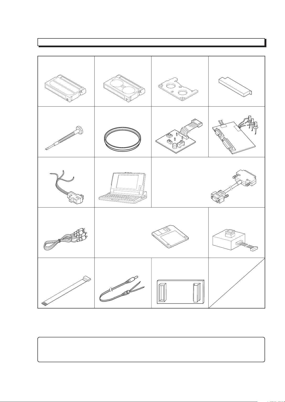
JIGS AND TAPES FOR SERVICE
1. Alignment Tape 2. Cassette Torque Meter 3. Master Plane 4. Reel Disk Height Jig
20HSC-3: No. 7099232 SRK-8T-232: No. 7099236 No.7099237 No. 7099238
SRK-8T-212: No. 7099402
5. Special Driver 6. C12 Light Balance 7. ATF-R Jig (*1,*2) 8. DSP-R jig
No. 7099239 Filter No. 7099461 No. 7099448
No. 7099369
9. DSP AV Output Jig 10.Presonal Computer 11. Personal Computer Cable
No. 7099456 [Goods on the market] RS-232C (9-pin or 25-pin)
Straight Type Cable
[Goods on the market]
12.AVOutput Cable (*3) 13.Adjustment Floppy Disk [New Jig] 14. 8 - 20 Pin Extention
[Accessory] No. TP12115 Cable
No. TS15411
15.4-Pin Extension Cable 16. ODC DC CORD 17.80-Pin Extention Board
No.7069203 No. TE13171 No. JP25461
Caution for jigs
*1. Always set SW3 on the ATF-R jig to ON.
*2. The ATF jig (No.7099386) can also be used in place of ATF-R jig to adjust this model.
*3. Either the monaural or stereo AV output cable can be used.
1 - 5
HOW TO USE THE EXTENSION CABLE AND JIG
Name of Jig Parts No. How to Use
8 - 20 Pin Extention TS15411 Used for electrical adjustment. Connected between PG905 on the VCA circuit board
Cable and DSP Output Jig (20 pins). Refer to Fig. 1-1 on the page 3-1.
4-Pin Extension Cable 7069203 Installed between the VCA circuit board and mode switch (mechanism state switch).
ODC DC Cord TE13171 Power supply cable for power shut off level (ODC) adjustment. Refer to Fig. 1-1 on the
page 3-1.
Positive: Black
Negative: Black & White
80-Pin Extension Board JP25461 Installed between the VCA circuit board and CON circuit board.
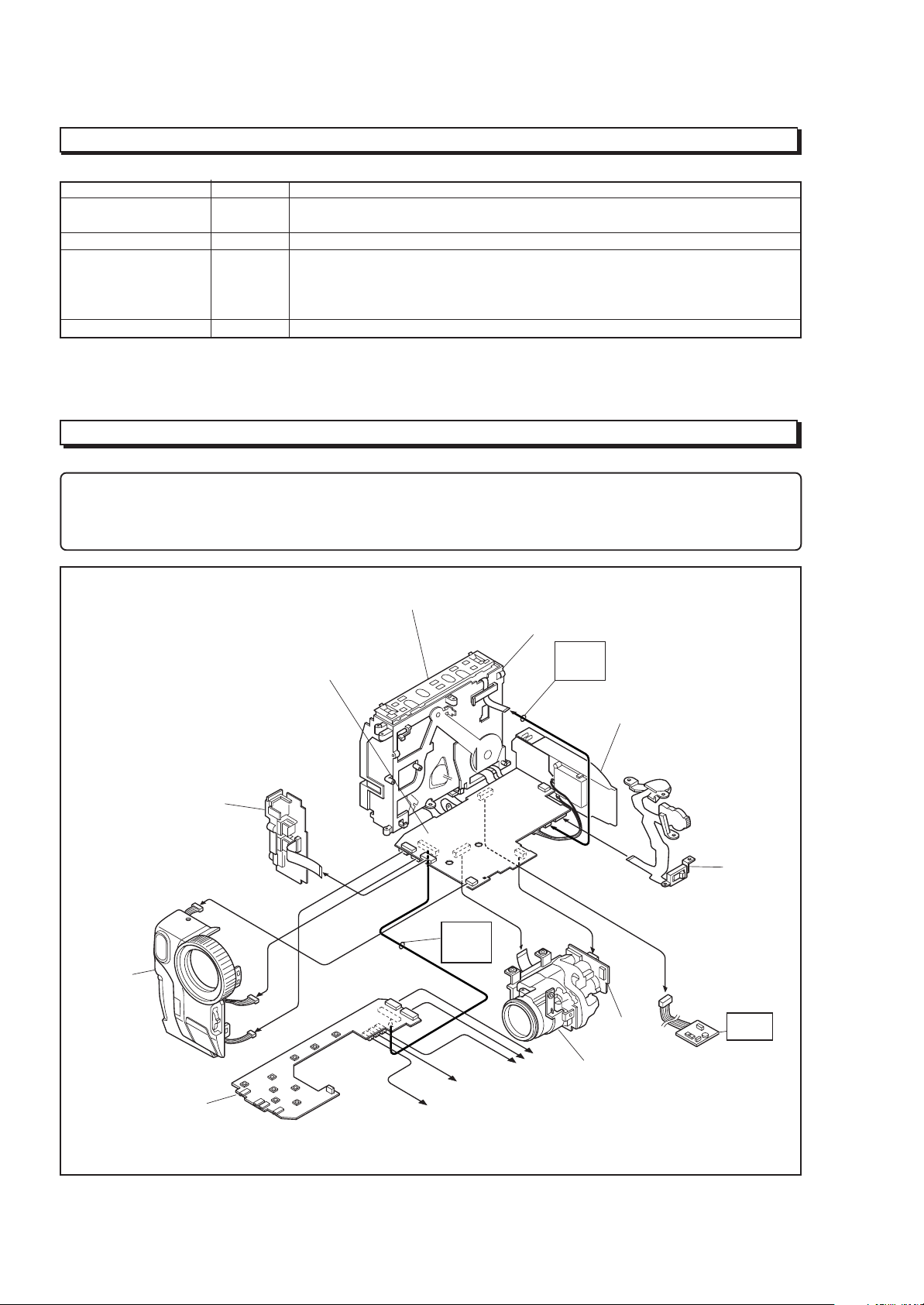
SERVICE POSITION
NOTE
1. If the front cover assembly is connected to the VCA circuit board, the provided remote control can be used to operate
the camera/recorder without connecting the CON circuit board.
2. The VCR block can be operated with the camera chassis assembly removed.
FRONT
COVER
ASSEMBLY
JACK
UNIT
CON
CIRCUIT
BOARD
VCA
CIRCUIT
BOARD
UH MECHANISM
80-PIN
EXT.
BOARD
To SPEAKER
To EVF
MECHANISM
FRAME
4-PIN
EXT.
CABLE
To LCD
REAR
UNIT
SE
CIRCUIT
BOARD
CAMERA
CHASSIS
ASSEMBLY
TW/PW
SWITCH
ATF-R
JIG
1 - 6
Fig.1-1 Service Position
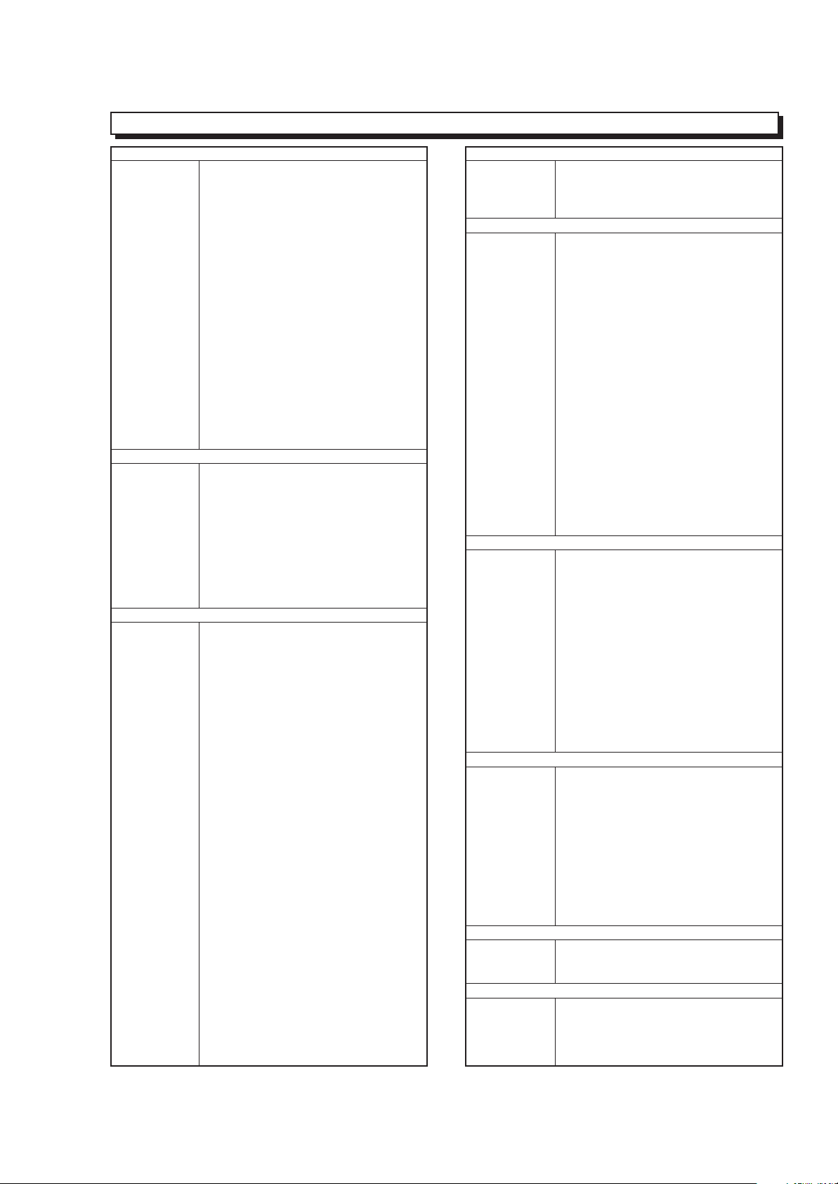
SERVICE MANUAL ABBREVIATION LIST
A
A (A-) Analog
ACC Automatic Color Control
A/D Analog-to-Digital Converter
ADD Adder
ADP. Adapter (AC Adapter)
ADRS Address
A.DUB Audio Dubbing
AF Automatic focus (Autofocus)
AFC Automatic Frequency Control
AGC Automatic Gain Control
AGC KILLER AGC Killer Voltage
AI Automatic Intelligence
AIC Automatic Iris Control
ALC Automatic Level Conrol
AMP Amplifier
APC Automatic Phase Control
ASBL Assemle (Phase Matching)
ATRS Auto Tape Recording System
AUD. Audio
AUX Auxiliary
B
B (BLU) Color Signal Blue
BATT. Battery
BF Burst Flag
BG Burst Gate or Back Ground
BGP Burst Gate Pulse
BLC Backlight Compensation
BLK Blanking
BPF Bandpass Filter
BUF. Buffer Amplifier
B-YL Color Difference Signal B-YL
C
C (CHROMA) Chrominance Signal
CAM Camera
CAPST. Capstan
CARRI. Carrier
CATV Cable TV
C.BLK Composite Blanking
CCD Charge Coupled Device
CDS Correlated Double Sampling
C.FG (CFG) Capstan Frequency Generater
C.FREE RUN Capstan Free Run
CG Character Generator
CH (Ch or ch) Channel
CHARA. Character
CHD Camera Horizontal Drive Pulse
C.MEMORY Counter Memory
CNR Chroma Noise Reducer
COM. Common
COMPA. Comparator
COMPE. Compensator
COMP-EXP Compressor-Expander
COMPO Composite
CONT. Control
CONV. Converter
COUNT. Counter
CP CP
C.PAUSE Camp Pulse
C/R Capacitor/Resistor
C.RESET Countor Reset or Camera Reset
C.REVERSE Count Reverse
CS Communication Signal
C
CST Cassette
C.SYNC Composite Synchronizing Signal
CTL Control Track Pulse (Control)
CYL Cylinder
D
D (D-) Digital
DA Double Azimuth
D/A Digital to Analog Converter
D-D Direct Drive
DEEMPHA. Deephasis
DEF Deflefction
DEMOD. Demodulator
DET Detector
DIFF. AMP Differential Amplifier
Digital 8 (D8) Digital 8 mm
DISP. Display
DL Delay Line
DO Dropout
DOC Dropout Compensator
DSP Digital Signal Processor
DUB Dubbing
DV Digital Video
DVD Digital Versatile Disc
D-VHS Digital VHS
D/W Dark/White
D.ZOOM (DZ) Digital Zoom
E
EAROM Electrically Alterable Read Only
Memory
E-E Electronic-to-Electronic
EEPROM Electrical Erasable Proframmed
Memory
EIS (E.I.S.) Electronic Image Stabilizer
EMPHA. Emphasis (EMPH)
EQ Equalizer
ESS End Sensor Supply (Supply End Sensor)
EST End Sensor Take-up
(Take-up End Sensor)
EVF Electronic Viewfinder
EXT. External
E.ZOOM Electrolical Zoom
F
F.ADV Frame Advance
FB Feed back
FE Full Erase
FF (F/F) Flip Flop
F.FWD Fast Forward
FG Frequency Generator
FM Frequency Modulation
FREQ. Frequency
fsc Sub Carrier Frequency
F/V Frequency-to-Voltage Converter
FWD Forward
G
G (GRN) Color Signal Green
GEN. Generator
GND Ground
H
H (HORIZ.) Horizontal
HB Hi-Band
HBF Horizontal Burst Flag
HD Horizontal Drive
1 - 7
H
Hi-Fi High Fidelity
HPF High-pass Filter
HSW Head Switch
I
IF Intermediate Frequency or Interface
INDI. Indicator
INST. Instant
INT. Internal
INV. Inverter
I/O In/Out (Input/Output)
IR Infrared Rays
L
LB Low-Band
LCD Liquid Crystal Dissplay
LIN. Linear
LM Loading Motor
LNC Line Noise Canceller
LOG Logarithm
LP Long Play
LPF Low-pass Filter
L/R Left/Right
LUMA Luminance
M
MAN Manual
M.BRAKE Main Brake
M.CUT Monitor Cut
MEM. Memory
MIC Microphone
MIX Mixer
MMV Monostable Multivibator
MOD. Modulator
MPEG Noving Picture coding Experts Group
M.STATE Mechanism State
M.STOP Memory Stop
N
NEG Negative
NFB Negative Feed Back
NOR. (NORM) Normal
NR Noise Reduction
O
OB Optial Black
OSC Oscillator
OSD On-Screen Display
P
PB (PLAY) Playback
PCM Pulse Code Modulation
PG Pulse Generator
PLL Phase Locked Loop
POS. Positive
PROG. Program
PROT. Protector
PWM Pulse Width Modulation
R
R (RED) Color Signal Red
RAM Random Access Memory
REC Record
RECT. Rectifier
REF. Reference
REG. Regulator
REV Review
REW Rewind
RF Radio Frequency
R
ROM Read Only Memory
RSS Reel Sensor Supply
(Supply Reel Sensor)
RST Reel Sensor Take-up
(Take-up Reel Sensor)
R-YL Color Difference Signal R-YL
S
SAW Sawtooth Signal
SC1 (0°) 3.58MHz Subcarrier Signal 1
(0-degree Phase Shifted)
SC2 (90°) 3.58MHz Subcarrier Signal 2
(90-degree Phase Shifted)
SEPA. (SEP) Separator
S/H Samle and Hold
SP Standard Play or Speaker
S.REEL Supply Reel Sensor
SRCH Search
SRV Servo
STABI. Stabilizer
S.TRACK Slow Tracking
STBY Standby Mode
S-VHS Super VHS
SW Switch
SW30Hz 30Hz Head Switching Pulse
(15 or 25Hz) (15 or 25Hz Head Switching Pulse)
SYNC Synchronizing signal
SYS.CON System Control
T
T (TELE) Telephoto Angle
TAPE + Recording Hi-8 Quality Image on Normal
Tape
TBC Time Base Corrector
T.BRAKE Take-up Brake
TP Test Point
T.REEL Take-up Reel Sensor
TRS Transfer
V
V (VERT.) Vertical
V.AGC AGC Voltage
VCO Voltage Controlled Oscillator
VCXO Voltage Controlled Crystal Oscillator
VD Vertical Drive
V.DUB Video Dubbing
VHS Video Home System
VOL. Volume
VP Voltage Pulse
W
W (WIDE) Wide Angle
WHD Wide Horizontal Drive
WHT Color Sifnal White
WHT BAL. White Balance
Y
Y Luminance Signal
Y/C Luminance/Chrominance
YEL (Ye) Color Signal Yellow
YL Luminance Signal (Low Component)
1 - 8

EXTRACT FROM THE INSTRUCTION MANUAL
VM-H775LE VM-E575LE
6
ENGLISH
IDENTIFYING CONTROLS
18. LCD Brightness Controls (p9)
19. 2.5-inch LCD Monitor (p9)
20. Speaker (p9)
21. Power Supply Attachment Section
(p16)
22. Clock Battery Compartment (p8)
23. Sub Power Switch (p24)
STANDBY: Pressing the Start/Stop button
will start recording.
LOCK: The camera/recorder will not
enter the record mode even if
the Start/Stop button is
pressed.
24. Start/Stop Button (p24, 28)
This works as a recording Start/Stop
button in the CAM mode and as a playback
pause button in the VIDEO mode.
25. BATT. EJECT Lever (p14)
Sliding, and then holding, this switch,
remove the battery from the camera/
recorder.
26. Shoulder Strap Slot (p12)
27. LCD Monitor OPEN Button (p14)
To open the LCD monitor.
28. DATE Button (p29)
To set the date or display it.
29. TITLE Button (p43)
To select or create a title, or display one.
30. EFFECT Button (p34)
To record digitally processed image or play
back picture with digital effect added.
31. FOCUS Control Buttons (p26, 32)
CAM mode: To switch between auto
focus and manual focus, or
to control focus while in
manual focus mode.
VIDEO mode: To control playback volume.
32. BLC (Backlight Compensation) Button
(p40)
When recording a subject in bright light,
hold this button down to compensate for
lighting on tape.
33. M ENU Button (p20)
To display the menu.
34. DC IN Jack (p17)
Use this jack to power the camera/recorder
from the AC adapter or from battery in
your vehicle.
19 20 21 23 24 25 262218
27
32 343328 29 30 31
[For VM-H775LE/E575LE]
IDENTIFYING CONTROLS
2 3 4 5 11 12 136
1
ENGLISH
jack cover) (p49)
16. Microphone Jack
Connect external microphone (not
supplied) here.
17. Audio/Video Output Jacks (Behind the
9 10 14 15 16 177
8
1. Built-in DC Light (p54) (for VM-H775LE)
2. Lens Door (p24)
The lens door will open automatically
when the camera/recorder is set to the
camera (CAM) mode.
Connect the provided AV cable from this
jack to the AV input jack of your TV or VCR.
The jacks on camera/recorder differ for
each model as follows:
VM-H775LE has S-VIDEO jack and stereo
audio output jacks.
VM-E575LE has monaural audio output
jack.
3. Power Zoom Control (p32)
4. Cassette Eject Switch (p18)
5. Shoulder Strap Slot (p12)
6. Charge Indicator (p13)
7. Record Indicator (p24)
8. Infrared Receiver (p24)
9. Microphone
tape.
10. CAM/OFF/VIDEO Power Switch (p24)
CAM: Set to this position to record.
VIDEO: Set to this position to play back a
11. Diopter Control (p11)
To adjust the viewfinder eyepiece to suit
your eyesight.
12. Electronic Viewfinder (p11)
13. DC Light Switch (p54) (for VM-H775LE)
To switch the DC light between ON, OFF
and AUTO.
14. Hand Strap (p12)
15. Cassette Holder (p18)
Insert cassette here.
5
1 - 9
29
ENGLISH
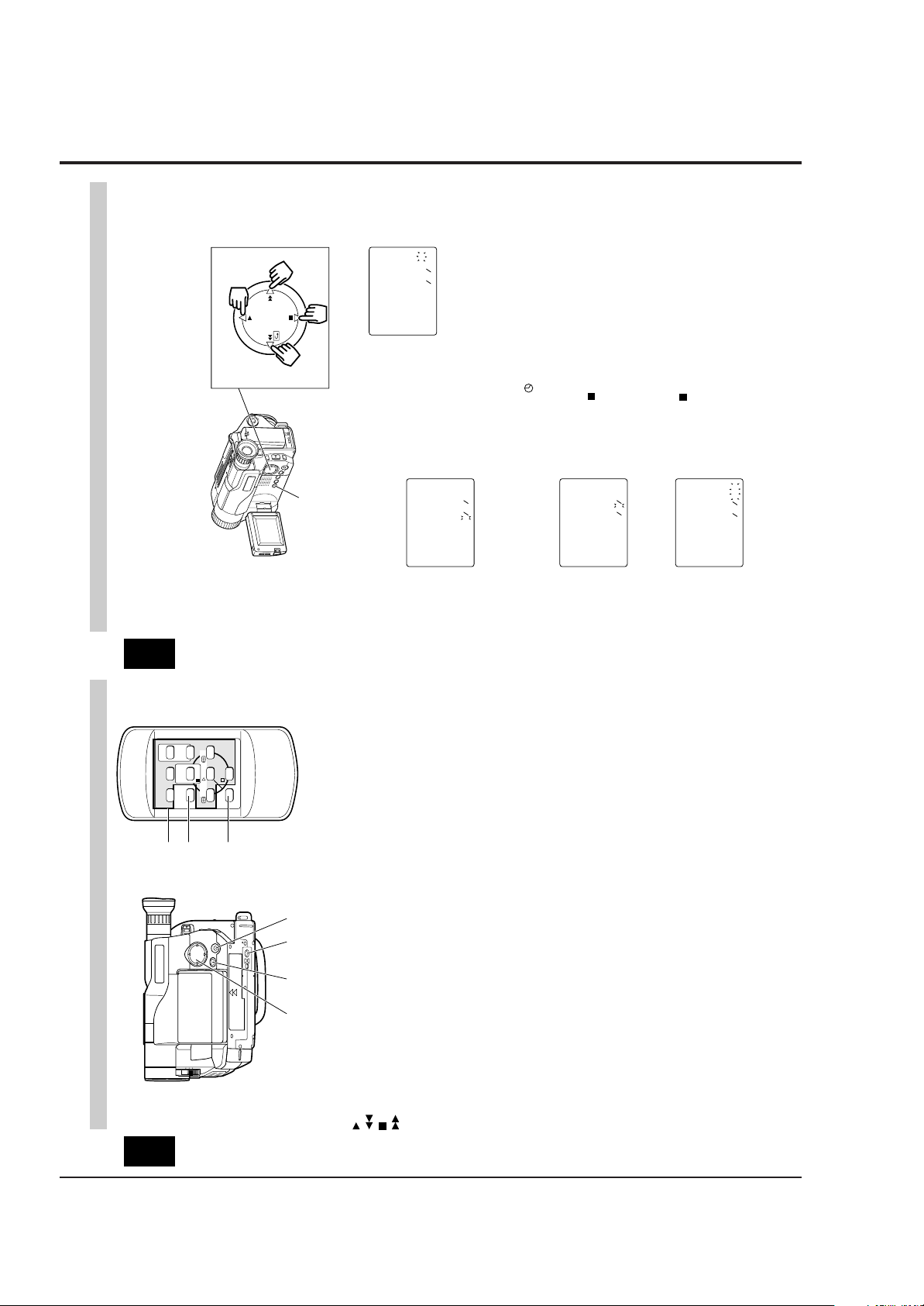
DATE/TIME SETTING
The date and time can be recorded on your tapes to act as a handy reference when
viewing them at a later time. Use the following procedure to set up this display for the
current date and time.
Make sure that the current time is displayed correctly before you start recording.
NOTE: Be sure to insert the clock battery before setting the date and time. Although the
date and time can be set without the clock battery inserted, they will disappear when the
battery providing power to the camera/recorder is removed.
1. Slide the CAM/OFF/VIDEO switch to
“CAM ” .
2. Press the DATE button.
“0:00” and “1/1/2000” appears on the
monitor screen and “ 1” flashes.
3. Press the PLAY or STOP button to select
correct date. Pressing the PLAY button
gives you higher numbers while the
STOP button gives you lower numbers.
When the correct date appears, press
the FF button.
4. Press the PLAY or STOP button to select
correct month. When the correct month
appears, press the FF button.
5. Use the PLAY, STOP and FF buttons to
select the correct year, hour and minute.
6. After setting to the correct minute, press
the DATE button to change the display
and start the internal clock.
It is recommended that you press the
DATE button to match the time signal.
NOTE: After the date and time are set,
“ AUTO” appears and the camera/
recorder enters the automatic date
recording mode. See “DATE RECORDING”
on page 30.
DATE Button
PLAY
STOP
REW FF
Date Select Buttons
000211
00:0
01021
30:6
511
0002
00:0
511
00021
00:0
511
To correct date/time after starting the
date/time
1. Hold down the DATE button for at least
3 seconds: The flashing cursor will
appear at the date.
2. Correct the incorrect digit by using the
PLAY, STOP and FF buttons.
To correct date/time during
programming
1. Press the FF button repeatedly until the
digit that is incorrect flashes.
2. Correct the incorrect digit by using the
PLAY, STOP and FF buttons.
1 - 10
T
W
ZOOM
PLAY F.FWDREW
STOP
PAUSE
TITLE
/STOP
START
ON/OFF
RESET
DISPLAY
COUNTER
A/V DUB
41
40
39
IDENTIFYING CONTROLS
ENGLISH
REMOTE CONTROL
remote control) (p48)
control) (p52)
39. Recorder Remote Control
Same functions as the corresponding
buttons on the camera/recorder.
40. COUNTER RESET Button (only on the
To reset the time counter to 0:00:00.
41. A/V DUB Button (only on the remote
To dub audio and video.
35 36 37 38
35. Tape Transport and Menu Setting
Buttons (p20, 26)
PLAY: To play back tape.
Tape Transport Buttons:
REW: To rewind tape.
FWD: To fast forward tape.
STOP: To stop tape.
Menu Setting Buttons:
To select menu items and set details.
36. FADE Button (p36)
To select the desired fade mode.
37. Tripod Mounting Threaded Socket
38. PROGRAM AE Button (p39)
To change the exposure.
7
To AC Outlet
ENGLISH
Removing the battery pack
Slide the BATT. EJECT lever in the
direction of the arrow and hold it; then
slide the battery to the upper side and
remove.
BATT. EJECT Lever
Operating time
The camera/recorder operating time
depends on how often you turn power on/
off and use start/stop and zoom.
Continuous recording
EVF: when using the viewfinder
LCD: when using the LCD monitor
14
However, if recording pause
continues for more than 5 minutes in
the CAM mode, the camera/recorder
will automatically turn off, after which
charging will start.
If the sub-power switch is set to
LOCK, charging will take place even
when the CAM/OFF/VIDEO switch is
set to CAM.
• If the DC plug is disconnected when
the battery is attached and the
CAM/OFF/VIDEO switch is set to CAM
or VIDEO, the camera/recorder will
turn off once, but then automatically
turn on again. Note that the battery
will discharge if the camera/recorder
is left as it is.
Charging time
Battery
Charging
VM-
BPL13
Full charge
75% charge
3h
1h 50 min.
VM-
BPL30
5h 30 min.
3h 40 min.
VM-
BPL60
9h 50 min.
7h
Reference of charged level
You can know the approximate charge
level of battery by observing how the
BATT. CHARGE indicator of camera/
recorder flashes or lights:
Charge level BATT. CHARGE indicator
0-50% charge
50-75% charge
More than
75% charge
Full charge
Flashes once at approx. one-
second intervals.
Flashes twice at approx. one-
second intervals.
Flashes three times at approx.
one-second intervals.
Steady light
Typical recording
EVF: when using the viewfinder
LCD: when using the LCD monitor
Notes on the battery
• It is recommended that the battery
always be left in the discharged state
when not in use, and charged before
you use it.
• Avoid storing a fully charged battery,
and do not store it in a place where the
temperature is high: this will damage
the battery.
• Do not operate the battery at
temperature below – 10 C or above 45 C.
At extremely low temperatures
operation time decreases, while at high
temperature the battery may be
damaged.
• Do not attach a hot battery to the
camera/recorder. Allow it to cool.
• There are no user-serviceable parts
inside the battery or AC adaptor.
• Throwing the battery into fire or
exposing it to excessive heat (above
60¡C) may cause injury.
• Shorting the battery’s terminal
increases risk of fire or electrical shock.
Battery
VM-BPL13 VM-BPL30 VM-BPL60
EVF
LCD
2h 40 min
2h 15 min
5h 55 min
5h
12h
10h 20 min
VM-H775LE
EVF
LCD
2h 50 min
2h 25 min
6h 15 min
5h 30 min
12h 40 min
11h 10 min
VM-E575LE
Battery
VM-BPL13 VM-BPL30 VM-BPL60
EVF
LCD
1h 35 min
1h 20 min
3h 30 min
3h
7h 10 min
6h 10 min
VM-H775LE
EVF
LCD
1h 45 min
1h 30 min
3h 45 min
3h 15 min
7h 35 min
6h 40 min
VM-E575LE
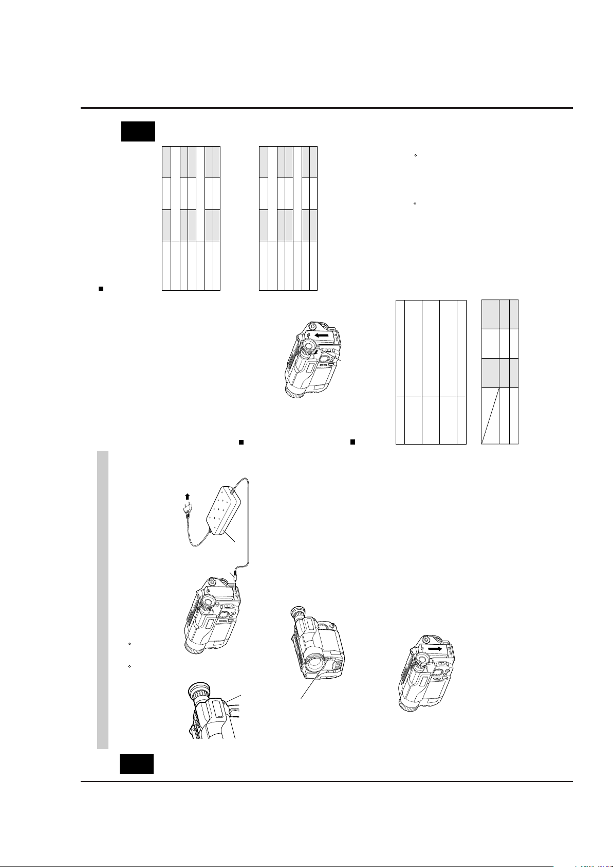
CHARGING THE BATTERY
AC Adaptor
DC Plug
indicator of the camera/recorder will
flash or light to give you a reference of
To DC IN Jack
flashes once every two seconds, the
battery could be defective.
light at all when the AC adaptor is
defective.
the charged level.
NOTES:
• If the BATT. CHARGE indicator
• The BATT. CHARGE indicator will not
completely charged.
• You can use the battery before it is
• When charging is complete, the
BATT. CHARGE Indicator
BPL30/VM-BPL60.
The first step is to set the battery for charging. To charge the battery, attach it to the
when you use battery packs other than those specified.
camera/recorder, and connect the VM-ACE5E AC adaptor. Charge the battery at a
temperature range of 10 C – 30 C to prevent damage to the battery.
NOTES:
• This camera/recorder operates with a lithium ion battery such as VM-BPL13/VM-
• We cannot be responsible for any malfunctions of the camera/recorder which occur
ENGLISH
set to OFF position.
CAM/OFF/VIDEO
Charge the battery on a flat surface that is
free of vibration.
Switch
1. Make sure the CAM/OFF/VIDEO switch is
2. Attach the battery pack to the camera/
BATT. CHARGE indicator on the
camera/recorder will light. If the fully
charged battery is removed and then
re-attached, the camera/recorder will
again enter the charge mode, and the
BATT. CHARGE indicator will flash. It
will take a few minutes for the
camera/recorder to enter the charge
complete status.
decrease charge capacity.
• Charging at low temperatures will
the AC adaptor DC plug from the
5. After charging is complete, disconnect
platform and slide it down so that it
fits into the camera/recorder.
recorder.
• Place the battery on the guide
camera/recorder after use.
OFF/VIDEO switch of the camera/
camera/recorder.
outlet.
recorder.
NOTES:
6. Disconnect the AC plug from the AC
NOTE: Always attach a battery only by
the procedure described here.
Attaching a battery forcibly could
• Always remove the battery from the
7. Detach the battery from the camera/
damage it.
AC outlet.
3. Plug the AC adaptor power cord into an
4. Connect the AC adaptor DC plug to the
recorder is set to CAM or VIDEO.
• Charging is not done when the CAM/
DC IN jack of the camera/recorder.
Charging will start within five seconds.
During charging, the BATT. CHARGE
13
1 - 11

20
ENGLISH
ITEMS SELECTABLE WITH MENU DISPLAY S
The items that can be selected depend on the position of CAM/OFF/VIDEO switch.
NOTE: The VM-H775LE menu displays are used for the following explanation. Some
items do not appear, depending on the model.
Menu selectable in the CAM mode
When the MENU button is pressed, the following menu display will appear:
M
ENU
EIS
W
H I T E BA L . AUTO
D.ZOO
M
X100
TAPE+ OFF
ATRS OFF
DISPLAY LCD
DE
M
O.
<>
END
AUTO
OFF
M
ENU
To correct camera shake (p41).
To lock the white balance
(p40).
To record in optimum status
to match tape being used
(p23) (only for VM-H775LE).
To turn the on-screen display
on or off (p22).
To select the demonstration
mode (p22).
To select the digital zoom
mode (p33).
To upgrade normal tape
(p23) (only for VM-H775LE).
Menu selectable in the VIDEO mode
Pressing the MENU button will display the following:
M
ENU
TBC
PAL CONV . OFF
DISPLAY LCD
<>
END
ON
M
ENU
To ensure playback of
stable pictures (p42).
To view NTSC tape
recorded in SP mode (p53).
To turn the on-screen
display on or off (p22).
How to select items and set them
1. Press the MENU button.
2. Press the PLAY or STOP button to select
the desired item.
3. Use the FF or REW button to select the
desired mode.
4. Press the MENU button again to
determine the mode.
PLAY
STOP
REW FF
To select an item whose
mode you wish to change.
Press PLAY to move the
cursor up.
To select the mode of the
item you have chosen.
To select an item whose
mode you wish to change.
Press STOP to move the
cursor down.
Memo
1 - 12

CHAPTER 2 DISASSEMBLY
1. BEFORE STARTING DISASSEMBLY
(1) Dismantle and reassemble the mechanism in loading
stop status, except for the following components:
Cassette Lid
Top Cover
Parts on the UH mechanism
Note: After dismantling or resembling the cassette lid
or top cover, return the mechanism to loading
stop status.
(2) For manually operating the mechanism (unloading or
loading), refer to: "How to Operate the Mechanism
Manually".
(3) Dismantle each component according to "1.1
Disassembly Procedure".
(4) For reassembly, perform the reverse procedure to
disassembly when not otherwise specified.
(5) Disconnect flat cables from connectors by the proce
dure shown in Fig. 1-1. Since many circuit boards in
the camera/recorder are connected by in-board
connectors, be sure to follow DISASSEMBLY when
removing the circuit boards.
(1) Release the lock of the connector on the left and right
simultaneously.
(2) Pull out the flat cable.
(1)
(1)
(2)
Fig. 1-1
1.1 Disassembly Procedure
Jack Cover,
Front Cover
Assembly [2.1]
Lens Cover [2.1]
Eye Piece [2.10]
LCD Case-U,
LCD Block [2.3]
PSW Circuit Board,
Microphone Unit,
DC Light,
Front Cover [2.2]
L-Case Assembly,
R-Case Assembly
[2.4]
LCD Circuit Board,
Back Light,
LCD Module,
LCD Case-B [2.9]
EVF Assembly
[2.5]
Speaker,
CON Circuit Board
[2.5]
Fulcrum [2.5]
Camera Chassis
Assembly [2.6]
EVF Case-R,
EVF Case L,
[2.10]
L-Case [2.5]
Lens Frame, Lens,
SE Circuit Board,
CCD Sensor [2.6]
Power Terminal
Unit [2.6]
Cassette Lid,
Top Cover [2.3]
(Note 1)
Note 1: Dismantle or reassemble these parts in loading
stop status; after finishing, return the mechanism
to loading stop status.
VCR Chassis
Assembly,
Jack Unit,
Rear Cover [2.6]
VCA Circuit Board,
Mechanism Frame,
UH Mechanism
[2.7]
Hand Strap,
TW/PW Switch,
R-Case [2.8]
2 - 1
2. CASES AND CIRCUIT BOARDS REMOVAL
A
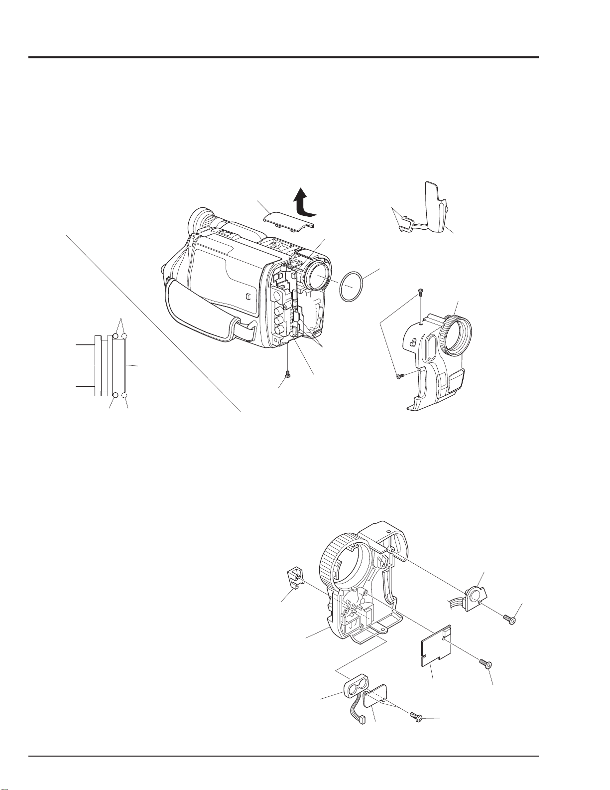
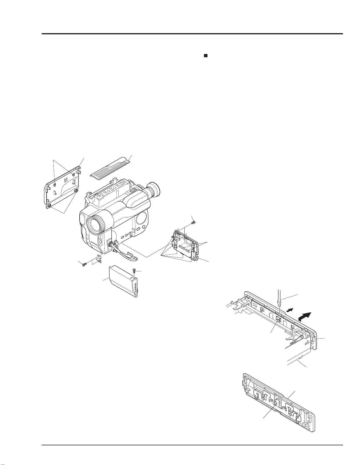
2.1 Jack Cover, Front Cover Assembly, Lens Cover (Fig. 2-1)
Note:Some models are not equipped with the DC light.
Cautions:
Be careful not to damage the cables of the microphone.
LENS
COVER
Reinstallation procedure and caution:
The O-ring must be installed in the position shown in Fig.
2-1.
DISCONNECT
CONNECTOR
[For DC LIGHT]
RELEASE
TWO
TABS
O-RING
JACK
COVER
FRONT COVER
ASSMBLY
GOOD
O-RING
NO GOOD
LENS
SURFACE
REMOVE
ONE
SCREW
VCA
CIRCUIT
BOARD
REMOVE
TWO
SCREWS
DISCONNECT
TWO
CONNECTORS
Fig. 2-1
2.2 PSW Circuit Board, Microphone Unit, DC Light, Front Cover (Fig. 2-2)
Note:Some models are not equipped with the DC light.
Reinstallation procedure and caution:
Take care with the orientation of the microphone when
reinstalling it: The red wire is for the left side; the white
lead is for the right side.
DJ. LID
DC
LIGHT
REMOVE
ONE
SCREW
FRONT
COVER
MICROPHONE
(MIC)
MIC
PLATE
PSW CIRCUIT
BOARD
REMOVE
TWO
SCREWS
REMOVE
ONE
SCREW
Fig. 2-2
2 - 2
2.3 LCD Case-U, LCD Block, Cassette Lid, Top Cover (Figs. 2-3-1, 2-3-2)
(C)
(B)
FLAT-BLADED
SCREW DRIVER
REMOVE
TOP
COVER
TOP
COVER
SUB CHASSIS
PLATE
SPRING
Cautions:
1. Dismantle and reassemble only the cassette lid and top
cover in loading stop status. After work is completed,
return the mechanism to loading stop status.
2. Be careful that the LCD screen is not damaged or
smudged. (If dirt adheres to it, use a soft cloth to wipe it
off.)
3. Handle the LCD module and backlight with extreme
care.
(A)
RELEASE
TWO T ABS
CASSETTE
LID
TOP COVER
REMOVE
TWO
SCREWS
Advise of Top Cover Removal
Insert a flat-bladed screwdriver between the top cover and
sub chassis, and push section (B) of the plate spring in the
direction of arrow (C), to remove the top cover in the
direction of the arrow. (See Fig. 2-3-2)
Reinstallation procedure and caution:
To install the cassette lid, first engage sections (A) with the
cassette holder.
REMOVE
TWO
SCREWS
LCD
CASE-U
REMOVE
ONE
SCREW
Fig. 2-3-1
RELEASE
FIVE T ABS
DISCONNECT
TWO
CONNECTORS
LCD BLOCK
Fig. 2-3-2
2 - 3

2.4 L-Case Assembly, R-Case Assembly (Fig. 2-4)
Caution:
Be careful so as not to damage the connectors (PG951
and PG731) between the VCA and CON circuit boards.
L-CASE
ASSEMBLY
R-CASE
ASSEMBLY
Reinstallation procedure and caution:
Connect connectors PG951 and PG731 securely.
REMOVE
TWO
SCREWS
2 - 4
PG731
CON
CIRCUIT
BOARD
REMOVE
FOUR
SCREWS
PG951
Fig. 2-4
VCA
CIRCUIT
BOARD
2.5 Electronic Viewfinder (EVF) Assembly, Speaker, CON Circuit Board, Fulcrum, L-Case
(Figs. 2-5-1, 2-5-2)
Cautions:
Be careful not to damage the LCD Open/Close switch on
the CON circuit board.
REMOVE
FULCRUM
L-CASE
TWO
SCREWS
DISCONNECT
CONNECTOR
[To SPEAKER]
EVF
ASSEMBLY
Reinstallation procedure and caution:
When reinstalling the EVF assembly, speaker, CON
circuit board and fulcrum, lay out each cable as shown
in Fig. 2-5-2.
DISCONNECT
THREE
CONNECTOR
[To LCD]
S
DISCONNECT
CONNECTOR
[To EVF]
REMOVE
THREE
SCREWS
CON
CIRCUIT
BOARD
REMOVE
THREE
SCREWS
Fig. 2-5-1
SPEAKER
EVF
ASSEMBLY
REMOVE
TWO
SCREWS
SP
BRACKET
SPEAKER
BOSS
CLOTH TAPE
CON CIRCUIT
BOARD
L-CASE
FULCRUM
Fig. 2-5-2
2 - 5
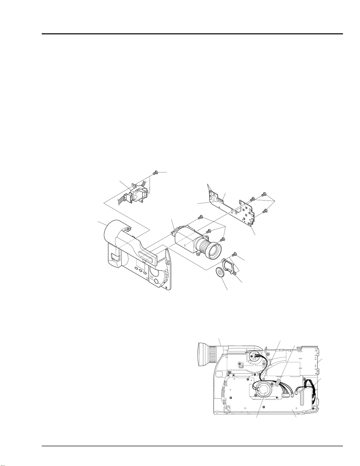
2.6 Camera Chassis Assembly (Lens Frame, Lens, SE Circuit Board, CCD Sensor),
VCR Chassis Assembly, Jack Unit, Rear Cover, Power Terminal Unit (Fig. 2-6)
Cautions:
1. Be careful so as not to damage the connectors (PG201
and PG1001) between the VCA and SE circuit boards.
2. Be careful so as not to damage the connectors
between the VCA circuit board (PG0001) and rear
cover (power terminal unit).
3. Be careful not to damage the crystal filter and CCD
sensor.
REMOVE
ONE
SCREW
VTR CHASSIS
ASSEMBLY
DISCONNECT
FLAT CABLE
DISCONNECT
CAMERA
CHASSIS
ASSEMBLY
FLAT CABLE
Reinstallation procedure and caution:
1. Connect connectors PG201 and PG1001 securely.
2. Connect connectors PG0001 and rear cover (power
terminal unit) securely.
3. The crystal filter is non-directional.
4. Fit in the CCD sensor parallel to the SE circuit board,
fix it with screws, and then solder it.
JACK
UNIT
A
R-CASE
RELEASE
PG201
DISCONNECT
CONNECTOR
ONE T AB
A
REMOVE
THREE
SCREWS
LENS
CRYSTAL
FILTER
SHADING
RUBBER
REMOVE
THREE
SCREWS
LENS
FRAME
CCD
SENSOR
UNSOLDER
FOURTEEN
POINTS
SE
CIRCUIT
BOARD
PG1001
Fig. 2-6
VCA
CIRCUIT
BOARD
REMOVE
TWO
SCREWS
REMOVE
TWO
SCREWS
DISCONNECT
FLAT CABLE
PG0001
REMOVE
ONE
SCREW
POWER
TERMINAL
UNIT
RELEASE
THREE
TABS
REAR
COVER
REMOVE
ONE
SCREW
2 - 6
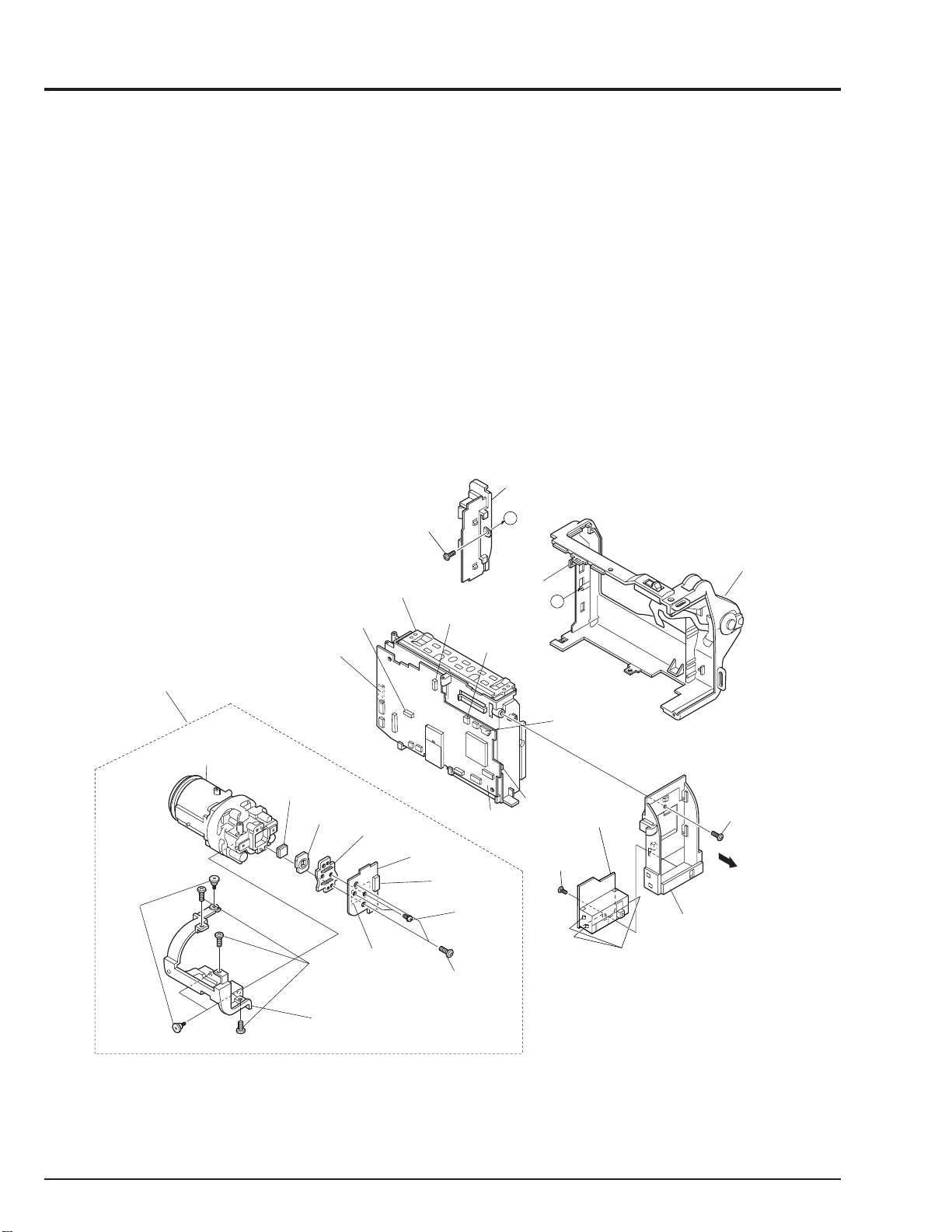
2.7 VCA Circuit Board, Meacanism Frame, UH Mechanism (Fig. 2-7)
D
C
UH
MECHANISM
VCA CIRCUIT
BOARD
ISCONNECT
ONNECTOR
DISCONNECT
TWO
FLAT CABLES
REMOVE
ONE
SCREW
MECHANISM
FRAME
DISCONNECT
THREE
FLAT CABLES
HEAD
SHIELD
RELEASE
TWO T ABS
REMOVE
THREE
SCREWS
Fig. 2-7
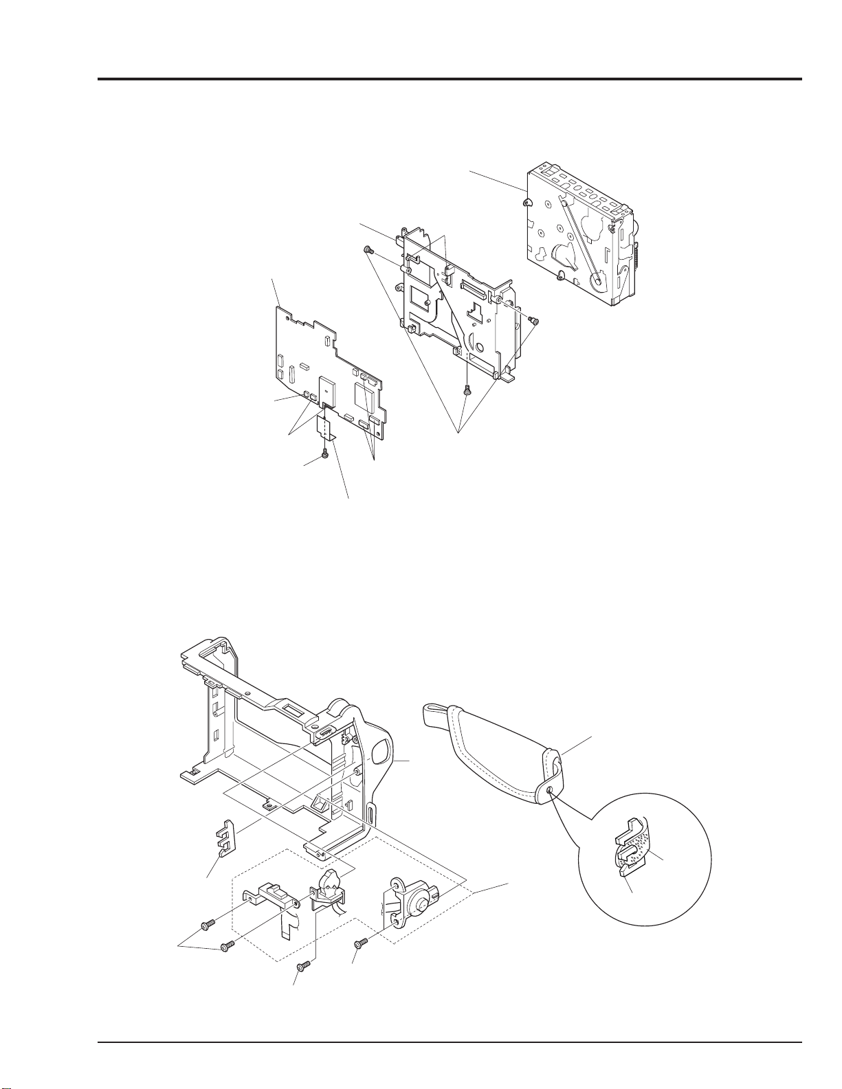
2.8 Hand Strap, TW/PW Switch, R-Case (Fig. 2-8)
Cautions:
Be careful not to damage the flat cable of the TW/PW
switch.
HAND
STRAP
R-CASE
TW/PW
HOLDER
REMOVE
TWO
SCREWS
REMOVE
ONE
SCREW
REMOVE
TWO
SCREWS
SWITCH
HOLDER
HAND
STRAP
Fig. 2-8
2 - 7
 Loading...