


WJ200-007SF
Hitachi WJ200-007SF, WJ200-002SF, WJ200-0015SF, WJ200-0022SF, WJ200-001LF Manual
...
Pursuing the Ideal Compact Inverter
Stöwer Antriebstechnik GmbH, Enneststrasse 3, 51702 Bergneustadt, tel: 02261-40970, Fax: 02261-41309
Pursuing the Ideal Compact Inverter
Series
Designed for excellent performance and user friendliness
2 3
3
4
5
0.5
1 3
6 10 20 30 40 50 60Hz
-100
-200
200
100
0
Speed (min-1)
(%)
Torque
Deceleration Time:
4.2 sec.
Deceleration Time:
1.9 sec.
OFF ON
Motor Current
DC Voltage
Output Frequency
DC Voltage
Output Frequency
Motor Current
Pursuing the Ideal Compact Inverter
Designed for excellent performance and user friendliness
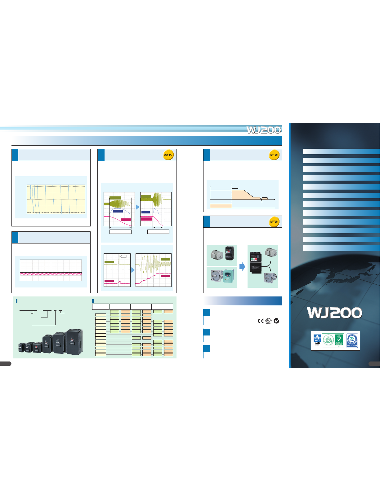
Industry-leading Levels of Performance
High starting torque of 200% or greater achieved
by sensorless vector control
(when sized for heavy duty
).
Speed regulation at low-speed is greatly impro ved.
–
Fluctuation is 1/2* compar ed with the previous model.
–
Trip avoidance functions
Conformity to global st andards
Sink / source logic is standard
Wide input power voltage range
Simple positioning contr ol
(when feedbac k signal is used.)
Induction motor & Permanent magnetic motor *
control with one inverter
(corresponds more than Ver.2.0)
1
2
1
2
3
Integrated auto-tuning function for easy sensorless vector cont rol
realizes high torque suit able for applications requiring it s uch as crane
hoists, lifts, elev ators, etc.
Minimum time deceleration function, over-current suppress function
and DC bus AVR function are incorporated. The functions reduce
nuisance t ripping. Improv ed torque limiting/current limiting function
enables a load limit to prot ect machine and equipment.
Speed regulation at low spe ed has been dras tically improve d to
enhance proce ss stability and precision.
CE, UL, c-UL, c-Tick approvals.
Logic input and output terminal can be congured for sink or source logic.
Input voltage 240V for 200V class and 480V for 40 0V class as standard.
When simple positioning function is activated, speed control operation or
positioning contr ol operation is select able via intellient input. W hile the [SPD]
input is ON, the current position counter is held at 0. When [SPD] is OFF, the
inverter enters positioning control operation and the position counter is active.
The WJ 200 inverter can drive both induc tion motors (IM) and permanent
magnetic mot ors (PM). Energy conservat ion and miniaturi zation can be
achieved using PM motors. Moreover, one inverter used for two types of motor.
Output Frequency
Start position counting
Speed control Position control
Target position
DB
Time
SPD input
ON
Example of Torque Char acteristic s
Model ConfigurationModel Name Indication
WJ200 – 001 L F
with Digit al Operator
Power Source
S: 1-phase 200V class
L: 3-phase 200V class
H: 3-phase 4 00V class
Applied Mot or Capacity
001: 0.1k W – 150 : 15kW
Series Name
PM
WJ200
IM
IM + Inverter
PM + Dedicat ed Contro ller
Auto-tuning to perform sensorles s vector control can now be easily done.
Model Name
WJ200-xxx
1-phase 2 00V clas s 3-phase 200V cla ss 3-phas e 400V c lass
VT CT VT CT VT CT
001 0.2 0.1 0.2 0.1
002 0.4 0.2 0.4 0.2
004 0.55 0.4 0.75 0.4 0.75 0.4
007 1.1 0.75 1.1 0.75 1. 5 0.75
015 2.2 1.5 2.2 1. 5 2.2 1.5
022 3.0 2.2 3.0 2.2 3.0 2.2
030 4.0 3.0
037 5.5 3.7
040 5.5 4.0
055 7.5 5.5 7. 5 5.5
075 11 7.5 11 7. 5
110 15 11 15 11
150 18.5 15 18.5 15
(Example of WJ20 0-055 LF)
• Frequency c ommanded by t he invert er: 0.5H z.
• Motor: H itachi's st andard 3- phase 5.5 kW 4-pol e totally en closed ty pe motor.
Example of Hi tachi's standar d motor. (7.5k W 4-pole)
2.3 sec. re duction of decelera tion time wit hout a braking
resistor i s achieved when the func tion is active.
Over-current Suppress Func tion*
Minimum time deceleration Funct ion
(Example of W J200- 075LF)
* WJ200: 5mi n-1, Previous mo del: 13min
-1
*Turn off this f unction for li fting equip ment.
*Permanen t magnet mot or control f unction of WJ 200 is for va riable torqu e applicatio n such as fan and p ump.
EC97J1095
Features P2–5
Standard Specicatio ns P6
General Specications P7
Dimensions P8
Operation and Programming P9
Termin al (Arrangements /Functions) P 1 0 – 11
Functi on List P 12– 2 0
Protectiv e Functions P 21
Connecting Diagram P 22– 23
OFF ON
Motor Current
Output Frequency
Motor Current
Output Frequency
Trip
Connecting to PLC P24
Wiring and Accessories P 25
For Correct Operation P 26 –27
Global standards
Index
3
Stöwer Antriebstechnik GmbH, Enneststrasse 3, 51702 Bergneustadt, tel: 02261-40970, Fax: 02261-41309

4 5
2
3
3
Watt-hour monitor
Output monitor ing
(2 terminals)
Improvement
of environmen t
2
EU RoHS
compliant
Environment-fr iendly
inverter meet s RoHS
requirements
(ordered items).
Energy consump tion is displayed in kwh.
Two monit or outpu t terminals
(A nal og 0 –10 VDC
(10-bit), pulse train (0–10VDC, max 32kHz))
.
5
EzCOM (Peer-to-Peer communication)
WJ200 supports Peer-to-Peer communication between multiple
inverters. One administrator inver ter is necessary in the networ k, and
the other inverters act as master or slave.
Varnish coating of
internal PC boar d is
standard.
(Logic PCB an d I/ F PCB ar e
excluded.)
Dual rating
1
WJ200 can be used for both heavy and
normal duty. One-frame-size smaller WJ200
can be applicable to cer tain applications.
Built-in BRD circuit
4
Built-in BRD circuit for all models (Op tional resist or).
1
6
5 7
4
Network compatibility & Ex ternal port s
2
3
Safe stop fun ction
(planning)
Password function
1
Easy sequence [EzS Q]
programming function
Pursuit of Ease of Use
Ease of Maintenance Environmental Friendliness
Long life time components
(Design life time 10 years or more*)
Easy-removable
cooling fan
Micro surge voltage suppress
function
(Patent re gistered)
Life time warning function
1 3
2
Sequence oper ation is realized by dow nloading to an inverter a
program crea ted with Hitachi's Ez SQ software. Us er program can
be compiled on E zSQ software on a PC. Exter nal components can
be simplied or eliminat ed, resulting in cost-sa vings.
Design lifetime 10 Years or more for D C bus
capacitors and c ooling fan.
Cooling fan ON /O FF control function fo r longer
fan life.
*Ambient temp erature : Av erage 40ºC (
no corrosiv e gases, oil mis t or dust
)
Design lifet ime is calculat ed, and not gua ranteed.
The cooler fan can b e exchanged
without special t ools.
Hitachi original P WM control method
limits motor termin al voltage to less than
twice inver ter DC bus voltage.
Lower than Hit achi motor max. insulation
voltage (1,250V )
(During rege neration, t he motor ter minal volta ge may exceed
the motor ma ximum insulat ion voltage (1, 250V))
WJ200 diagnoses lif etime of DC bus capacitors
and cooling fan(s).
The WJ200 inverter has a pas sword function t o prevent changing
parameters or to hide some or all par ameters.
Only one MC is enough
•Reduction in costs.
•Miniaturization
Safety Module
ST01 (GS1)
ST02 (GS2)
EDM
Safety terminal
(In/ output)
Emergency output
shut-down
via hardware
Safety SW
(Emergency Stop)
Top cover can
be removed
with nger tips.
Remove cooling
fan after
disconnect ing
power plug.
Motor ter minal voltag e
Easy to maintain
Easy select ion of displayed par ameters
●
Data compar ison function
Display paramete rs changed from def ault setting.
●
Basic display
Display most fre quently used parame ters.
●
Quick display
Display 32 user-selec ted parameters.
●
User-changed parameter display
Store automa tically and display the par ameters changed by
the user (Up to 32 sets); can also be used as change histor y.
●
Active pa rameter display
Display those par ameters which are en abled.
Inverters can be ins talled
with no space between them
to save space in the panel.
*Ambient temp erature 4 0ºC max.,
individual mounting.
Side-by-side ins tallation
6
Automatic r eturn to the initial display: 10 min. a fter the last
key operation , display returns to th e initial parameter se t.
Display limitatio n:
Show only the con tents of display par ameter.
Dual monitor: Two arbi trary monitor it ems can be set. Par ameters
are switche d by up/down keys.
Flexible display funct ions
Various Versatile Functions
Ease of wiring
Screw-less t erminals (control circuit
terminals) spring-lo aded, for use with
solid or strande d wire with ferrules.
Screw-less terminals
(Control circui t terminals)
E=625V cable:100m
A serial RS-4 85 Modbus/RT U port is stand ard. The WJ200 can
communicate via DeviceNet, CompoNe t, PROFIBUS and C ANopen
with optional e xpansion card
(planned) . USB (Mini-B c onnector) port
and RS-42 2 (RJ45 connect or) port are stan dard.
USB port
RS42 2 port
1st 2nd 3rd 4th 5th 6th 7th
Night time
Standard driving
(Frequency is constant.)
WJ200 driving
Motor Speed
date
●
EzSQ E xample: Energy cos t saving by speed r eduction.
■Daytime: Motor speed is automatically reduced to reduce demand during peak hours.
■Nighttime: Motor spee d is increased to t ake a advantag e of off-peak p ower rates.
Example of d riving progra m
Operation panel
(Switc h/tim er etc.)
Panel lead
Standard Inverter WJ200 U sing EzSQ
RUN
STOP
RESET
POWER
Hz
A
RUN
PRG
MAX
MIN
WJ200 confor ms to the applicable safet y standards and cor responds
to Machinery Dire ctive of Europe. Shut s down the inverter b y
hardware, byp assing the CPU, to achieve r eliable safe stop function.
The safet y standard can be met at a low cost.
(ISO13849 -1 Category 3 / IE C60204 -1 Stop Categor y 0)
One network ex pansion card can
be installed ins ide the WJ2 00.
Inverter
WJ200
Operation panel
(Switc h/tim er etc.)
Rely seque nce
Conventional
Inverter
Panel lead
Stöwer Antriebstechnik GmbH, Enneststrasse 3, 51702 Bergneustadt, tel: 02261-40970, Fax: 02261-41309

Standard Specications
Stöwer Antriebstechnik GmbH, Enneststrasse 3, 51702 Bergneustadt, tel: 02261-40970, Fax: 02261-41309
1-phase 200V class
Models WJ2 00- 00 1SF 002SF 004SF 007SF 0 15 S F 022SF
VT 0.2 0.4 0.55 1.1 2.2 3.0
kW
Applicable mot or size *
Rated capaci ty (kVA)
Input
Rating
Output
Rating
Minimum value of r esistor (Ω) 10 0 100 100 50 50 35
Weight
Rated input volt age (V ) 1-phase: 20 0V-15% to 240 V +10%, 50 / 60Hz ±5%
Rated inpu t current (A)
Rated output voltage (V) *
Rated output current (A)
1
3-phase 200V class
Models WJ2 00- 001L F 002LF 004LF 007LF 015 LF 022LF 037LF 055LF 075LF 110 LF 150 LF
Applicable mot or size *
Rated capaci ty (kVA)
Input
Rating
Output
Rating
Minimum value of r esistor (Ω) 100 10 0 100 50 50 35 35 20 17 17 10
Weight
Rated input volt age (V ) 3-phase: 200V-15% to 240V +10%, 5 0/ 60Hz ±5%
Rated inpu t current (A)
Rated output voltage (V) *
Rated output current (A)
1
CT 0.1 0.2 0.4 0.75 1.5 2.2
VT 1/4 1/2 3/4 1.5 3 4
HP
CT 1/8 1/4 1/2 1 2 3
VT 0.4 0.6 1. 2 2.0 3.3 4 .1
200V
CT 0.2 0.5 1.0 1.7 2.7 3.8
VT 0.4 0.7 1.4 2.4 3.9 4.9
240V
CT 0.3 0.6 1.2 2.0 3.3 4.5
VT 2.0 3.6 7.3 13.8 20.2 24.0
CT 1.3 3.0 6.3 11.5 16 .8 22.0
2
VT 1.2 1.9 3.5 6.0 9.6 12. 0
CT 1.0 1.6 3.0 5.0 8.0 11.0
kg 1.0 1.0 1.1 1.6 1.8 1. 8
lb 2.2 2.2 2.4 3.5 4.0 4.0
VT 0.2 0.4 0.75 1.1 2.2 3.0 5.5 7.5 11 15 18.5
kW
CT 0.1 0.2 0.4 0.75 1.5 2.2 3.7 5.5 7. 5 11 15
VT 1/4 1/2 1 1.5 3 4 7. 5 10 15 20 25
HP
CT 1/8 1/4 1/2 1 2 3 5 7. 5 10 15 20
VT 0.4 0.6 1.2 2.0 3.3 4.1 6.7 10. 3 13.8 19.3 23.9
200V
CT 0.2 0.5 1.0 1.7 2.7 3.8 6.0 8.6 11. 4 16. 2 20.7
VT 0.4 0.7 1.4 2.4 3.9 4.9 8.1 12.4 16.6 23.2 28.6
240V
CT 0.3 0.6 1.2 2.0 3.3 4.5 7.2 10.3 13.7 19.5 24.9
VT 1.2 1.9 3.9 7.2 10.8 13.9 23.0 3 7.0 48.0 68.0 72.0
CT 1.0 1.6 3.3 6.0 9.0 12 .7 20.5 30.8 39.6 57.1 62.6
2
VT 1.2 1.9 3.5 6.0 9.6 12. 0 19.6 30.0 40.0 56.0 69.0
CT 1.0 1.6 3.0 5.0 8.0 11.0 17.5 25.0 33.0 47. 0 60.0
kg 1.0 1.0 1.1 1.2 1.6 1.8 2.0 3.3 3.4 5.1 7.4
lb 2.2 2.2 2.4 2.6 3.5 4.0 4.4 7.3 7. 5 11. 2 16.3
3-phase: 200 to 240V (proportional to input voltage)
3-phase: 200 to 240V (proportional to input voltage)
3-phase 400V class
Models WJ2 00- 004HF 007HF 015HF 022HF 030HF 040HF 05 5HF 075HF 110HF 15 0HF
VT 0.75 1. 5 2.2 3.0 4.0 5.5 7. 5 11 15 18 .5
kW
Applicable mot or size *
Rated capaci ty (kVA)
Input
Rating
Output
Rating
Minimum value of r esistor (Ω) 180 180 180 100 100 100 70 70 70 35
Weight
*1: The ap plicable mot or refers t o Hitachi st andard 3- phase mot or (4p). Whe n using other motors, ca re must be ta ken to prev ent the rat ed motor cur rent (50/ 60Hz) fr om exceedi ng the rate d output cu rrent of th e inverte r.
*2: Th e output vo ltage vari es as the main s upply volt age varies (e xcept when using the AVR f unction). In any case, t he output v oltage can not exceed the input po wer supply v oltage.
6
Rated input volt age (V ) 3-phase: 380V-15% to 480 V +10%, 50 / 60Hz ±5%
Rated inpu t current (A)
Rated output voltage (V) *
Rated output current (A)
1
CT 0.4 0.75 1.5 2.2 3.0 4.0 5.5 7.5 11 15
VT 1 2 3 4 5 7. 5 10 15 20 25
HP
CT 1/2 1 2 3 4 5 7. 5 10 15 20
VT 1. 3 2.6 3.5 4.5 5.7 7.3 11.5 15.1 20.4 25.0
200V
CT 1.1 2.2 3.1 3.6 4.7 6.0 9.7 11. 8 15.7 20.4
VT 1. 7 3.4 4.4 5.7 7.3 9.2 14.5 19.1 25.7 3 1.5
240V
CT 1.4 2.8 3.9 4.5 5.9 7. 6 12.3 14.9 19.9 25.7
VT 2.1 4.3 5.9 8.1 9.4 13.3 20.0 24.0 38.0 44.0
CT 1.8 3.6 5.2 6.5 7.7 11.0 16.9 18.8 29.4 35.9
2
VT 2.1 4.1 5.4 6.9 8.8 11.1 17.5 23.0 31.0 38.0
CT 1.8 3.4 4.8 5.5 7.2 9.2 14.8 18. 0 24.0 31.0
kg 1.5 1.6 1.8 1.9 1. 9 2.1 3.5 3.5 4.7 5.2
lb 3.3 3.5 4.0 4.2 4.2 4.6 7.7 7. 7 10.4 11. 5
3-phase: 380 to 480 V (proportional to input voltage)
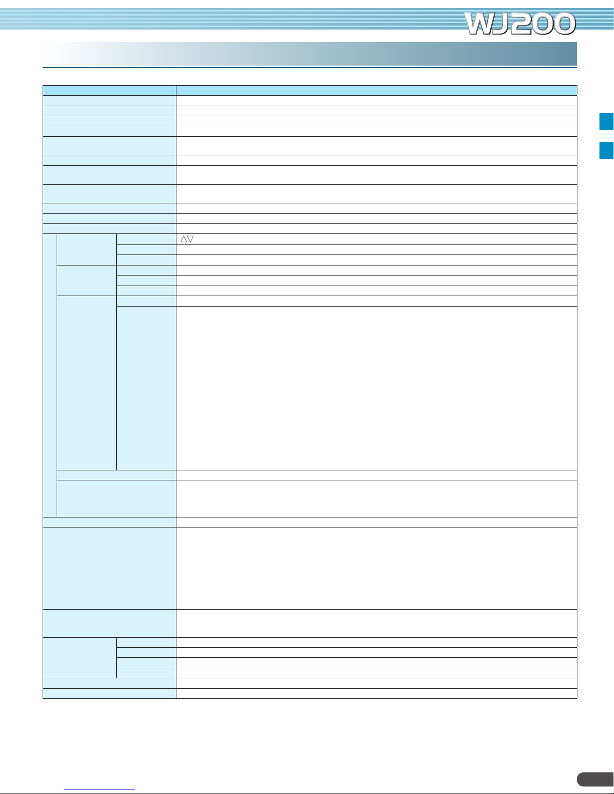
General Specications
Stöwer Antriebstechnik GmbH, Enneststrasse 3, 51702 Bergneustadt, tel: 02261-40970, Fax: 02261-41309
Item General Specications
Protect ive housing *
3
Control method Sinusoidal Pulse Width Modulation (PW M) control
Carrier frequency 2kHz to 15kHz (derating required depending on the model)
Output f requency range *
4
Frequency accuracy
Frequency set ting resolut ion Digital: 0.01Hz; Analog: max . frequency / 1000
Volt ./ Freq. character istic
Overload capacity
Acceleration /deceleration time 0.01 to 3600 seconds, linear and S-curve accel /decel, second accel /decel setting available
Start ing torque 200% @0.5Hz (sensorless ve ctor control)
DC braking Variable operating f requency, time, and braking force
Operator panel
Freq . setting
Ex ternal signal *
Via network RS485 ModBus RT U, other net work option
Operator panel Run / Stop (For ward /Reverse run change by command)
FW D/ REV run
Ex ternal signal *
Via network RS485 ModBus RT U, other net work option
Terminals 7 terminals, sink / source changeable by a short bar
Intelligent input
Input signal
terminal
68 funct ions
Functions
assignable
Intelligent output
terminal
Functions
48 f unctions
assignable
Output signal
Moni tor output (analog) Output freq., output current, output torque, output voltage, input power, thermal load ratio, L AD freq., heat sink temperature, general ou tput (EzSQ)
Pulse train output
(0 – 10VDC, 32 kHz max.)
Alar m output cont act ON for inverter alar m (1c contacts, both normally open or closed available.)
Other functions
Protect ive funct ion
Temperature Op erating (ambient): -10 to 50
Operating environment
Humidity 20 to 90% humidity (non-condensing)
Vibration *
Location Altitude 1,000m or less, indoors (no corrosive gasses or dust)
Coat ing color Black
Options Remote operator unit, cables for the units, braking unit, braking resistor, AC reactor, DC reactor, EMC lter
IP20
0.1 to 400Hz
Digital command: ±0.01% of the maximum frequency
Analog command: ±0.2% of the maximum frequency (25
°
C ±10°C)
V/f control (constant torque, reduced torque, free-V /F): b ase freq. 3 0Hz – 400Hz adjustable,
Sensorless vector control, Closed loop control with motor encoder feedback (only V/f control).
Dual rating: CT (Heavy duty): 60 sec. @150%
VT (Normal dut y): 60 sec. @120%
2
1
keys / Value set tings
6
0 to 10 VDC (input impedance 10kΩ), 4 to 20mA (input imp edance 100Ω), Potentiometer (1k to 2kΩ, 2W )
6
Forward r un /stop, Reverse run / stop
FW (forward run command), RV (reverse run command), CF1 – CF4 (multi-stage speed setting), JG (jog command), DB (external braking), SET (set second
motor), 2CH (2-stage accel. /decel. command), FRS (free run stop command), E XT (exter nal trip), USP (st artup function), CS (commercial power switchover),
SFT (soft lock), AT (analog input selection), RS (reset), P TC (thermistor thermal protection), STA (start), STP (stop), F /R (forward /reverse), PID (PID
disable), PIDC (PID reset), UP (remote control up function), DWN (remote control down function), UDC (remote control data clear), OPE (operator control),
SF1– SF7 (multi-stage speed setting; bit operation), OLR (overload restriction), TL (torque limit enable), TRQ1 (torque limit changeover1), TRQ2 (torque
limit changeover2), BOK (Braking conrmation), L AC (LAD cancellation), PCLR (position deviation clear), ADD (add frequency enable), F-TM (force terminal
mode), ATR (permission of torque command input), KHC (Cumulative power clear), MI1– MI7 (general purpose inputs for EzSQ), AHD (analog command hold),
CP1– CP3 (multistage-position switches), ORL (limit signal of zero-return), ORG (trigger signal of zero-return), SPD (speed/position changeover), GS1,GS2 (STO
inputs, safety related signals), 485 (Starting communication signal), PRG (executing EzSQ program), HLD (retain output frequency), ROK (permission of run
command), EB (rotation direction detection of B-phase), DISP (display limitation), NO (no function)
RUN (run signal), FA1 –FA 5 (frequency arrival signal), OL,OL2 (overload advance notice signal), OD (PID deviation error signal), A L (alarm signal),
OTQ (over / under torque thre shold), UV (under-voltage), TRQ (torque limit signal), RNT (run time expired), ONT (power ON time expired), THM (thermal
warning), BRK (brake release), BER (brake error), ZS (0Hz detection), DSE (speed deviation excessive), POK (positioning completion), ODc (analog
voltage input disconnection), OIDc (analog cur rent input disconnection), FB V (PID second stage output), NDc (network disconnec t detection), LOG1 –
LOG3 (Logic output signals), WAC (capacitor life warning), WA F (cooling fan warning), FR (st arting contact), OHF (heat sink overheat warning), LOC
(Low load), MO1 –MO3 (general outputs for EzSQ), IRDY (inver ter ready), FWR (forward operation), RVR (reverse operation), M JA (major failure),
WCO (window comparator O), WCOI (window comparator OI), FREF (frequency command source), REF (run command sour ce), SETM (second motor in
operation), EDM (STO (safe torque off ) per formance monitor), OP (option control signal), NO (no function)
[PW M output]
Output fre q., output current, output torque, output voltage, input power, thermal load ratio, LAD freq., heat sink temperature, general output (EzSQ)
[Pulse train output]
Output frequency, output cur rent , pulse train input monitor
Free-V/f, manual / automatic torque boost, output voltage gain adjustment, AVR function, reduced voltage start, motor data selection, autotuning, motor stabilization control, reverse r unning protection, simple position control, simple torque control, torque limiting, automatic carrier
frequency r educ tion, energy saving operation, PID function, non-stop operation at instantaneous power failure, brake control, DC inje ction
braking, dynamic braking (BRD), f requency upper and lower limiters, jump frequencies, curve accel and decel (S, U, inversed U,EL-S), 16-stage
speed prole, ne adjustment of st art frequency, accel and decel stop, process jogging, frequency calculation, frequency addition, 2-stage
accel/decel, stop mode selection, start /end freq., analog input lter, window comparators, input terminal response time, output signal delay/
hold function, rotation direction restriction, stop key sele ction, sof tware lock, safe stop function, scaling function, display restriction, passwor d
function, user p arameter, initialization, initial display selection, cooling fan control, warning, trip retry, frequency pull-in r estart, frequency
matching, overload restriction, over current restriction, DC bus voltage AVR
Over-current, over-voltage, under-voltage, overload, brake resistor overload, CPU error, memory error, external trip, USP error, ground fault detection
at power on, temperature error, internal communication error, driver error, thermistor error, brake error, safe stop, overload at low speed, modbus
communication error, option error, encoder disconnection, speed excessive, EzSQ command error, EzSQ nesting error, EzSQ execution error, EzSQ user trip
°
C / Stor age: -2 0 to 65°C *
8
5.9m/s2 (0.6G), 10 to 55 Hz
7
*3: Th e protect ion method conforms t o JEM 1030.
*4: To operat e the motor b eyond 50 / 60Hz, c onsult the m otor manuf acturer f or the maxim um allowable r otation sp eed.
*5: Th e brakin g torque via ca pacitive feedbac k is th e averag e decele ration t orque at the sh ortest deceler ation (st opping f rom 50 / 60Hz as indic ated). I t is no t continu ous rege nerative braking torque. The a verage d ecelerati on
torqu e varies wit h motor los s. This value d ecreases w hen opera ting beyon d 50Hz. If a large rege nerative t orque is req uired, the o ptional reg enerativ e braking uni t and a resis tor should be u sed.
*6: T he frequenc y command is t he maximum f requency a t 9.8V for inp ut voltage 0 t o 10VDC , or at 19.6mA fo r input curr ent 4 to 20mA . If this char acterist ic is not satis factory f or your applic ation, cont act your Hit achi repre sentativ e.
*7: The stora ge tempera ture refe rs to the sho rt-term t emperatur e during tr ansport ation.
*8: Co nforms to t he test met hod speci ed in JIS C0 040 (1999) . For the mo del types excluded in t he standar d specic ations, con tact your H itachi sale s represe ntative.
7

Dimensions
Stöwer Antriebstechnik GmbH, Enneststrasse 3, 51702 Bergneustadt, tel: 02261-40970, Fax: 02261-41309
• WJ200-001LF – 007LF
• WJ200-001SF – 004SF
68 (2.68)
WJ200 INVERTER
PWR
RUN
Hz
ALM
A PRG
STOP
RUN
1
RESET
ESC
2 SET
128 (5.04)
118 (4.65)
5 (0.20)
56 (2.20)
D
Ø4.5 (0.18)
Model D
001LF, 002LF
001SF, 00 2SF
109 (4. 29)
004 LF, 004SF 122. 5 (4.82)
007LF 145.5 ( 5.73)
• WJ200-055LF
• WJ200-075LF
• WJ200-055HF
• WJ200-075HF
248 (9.76)
260 (10.24)
155 (6.10)
140 (5.51)
6 (0.24)
122 (4.80)
[Unit : mm(inch)]
Inche s for refere nce only
Ø6 (0.24)
WJ200 INVERTER
PWR
RUN
Hz
ALM
A
PRG
STOP
RUN
1
RESET
ESC
2 SET
• WJ200-015LF, 022LF
• WJ200-007SF – 022SF
• WJ200-004HF – 030HF
108 (4.25)
WJ200 INVERTER
RUN
Hz
A PRG
STOP
RUN
1
RESET
ESC2SET
128 (5.04)
118 (4.65)
5 (0.20)
96 (3.78)
D
• WJ200-037LF
• WJ200-040HF
140 (5.51)
WJ200 INVERTER
RUN
1
ESC2SET
128 (5.04)
118 (4.65)
• WJ200-110LF
• WJ200-110HF
• WJ200-150HF
Ø4.5 (0.18)
PWR
ALM
296 (11.65)
Model D
004HF 143.5 ( 5.65)
Other 170.5 (6.7 1)
175 (6.89)
284 (11.18)
7 (0.28)
180 (7.09)
WJ200 INVERTER
STOP
RUN
1
RESET
ESC2SET
160 (6.30)
Ø7 (0.28)
RUN
PWR
Hz
ALM
A
PRG
• WJ200-150LF
220 (8.66)
Ø7 (0.28)
WJ200 INVERTER
RUN
PWR
Hz
ALM
A
PRG
STOP
RUN
PWR
RUN
Hz
ALM
A PRG
STOP
RESET
Ø4.5 (0.18)
336 (13.23)
350 (13.78)
ESC2SET
1
RESET
5 (0.20)
128 (5.04)
170.5 (6.71)
8
175 (6.89)
7 (0.28)
192 (7.56)

Operation and Programming
Stöwer Antriebstechnik GmbH, Enneststrasse 3, 51702 Bergneustadt, tel: 02261-40970, Fax: 02261-41309
Operation Panel
WJ200 Series can be easily operated with the digital operator provided as standard.
( 4 ) Run LED
ON when inverter is in RUN mode.
( 5 ) Monitor L ED [Hz]
ON (Green) when the displayed data is
frequency related.
( 6 ) Monitor LED [A]
ON (Green) when the displayed dat a is
current related.
( 8 ) 7-segment L ED
Shows each parame ter, monitors etc.
( 7 ) Run command LED
ON (Green) when the Run command is set to the
operator. (Run key is enabled.)
( 9 ) RUN key
Makes inver ter run.
(11) Escape key
Go to the top of next function group,
when function mode is displayed.
(12) Up key (13) Down key
Press up or down to sequence through parameters and functions
shown on the display, and increment/decrement values.
(1 ) POWER LED
ON (Green) while t he inverter is receiving
input power.
( 2 ) AL ARM LED
ON (Red) when the inver ter trips.
( 3 ) Program L ED
ON (Green) when the display shows
editable parameter.
(15) USB port
USB connector (mini-B) for PC communication.
(10) Stop /reset key
Makes inverter stop.
(16) RS-422 port
RJ4 5 jack for remote operator.
(14) Set key
Function code: Moves to the data display.
Data code: Press to write the new value
to EEPROM.
Keypad Navigation Map Single-Digit Edit Mode
If a target function code or data is far from current
posit ion, using the single-digit edit mode makes it
quicker to navigate there. Pressing the up key and
down key at the same time brings you into the
digit-by-digi t navigation mode.
Press both up key and down key at
Step1:
the same.
1st digit will be blinking.
Group "d"
Function co de
Group "F "
Function co de
Func tion code di splay
:
Moves to dat a display
Data display
Func tion code di splay
: Chang e the value of fun ction code.
Pressing the up key at the bot tom of the group returns to the top of the group.
Func tion code di splay
: Jumps t o the next gr oup
Save
Data display
d001: Output frequency monitoring
F001: Output frequency setting
Function group "d" is a monitor,
data c annot be changed.
Data display (F001 to F003)
Data d oes not blink becaus e of real time s ynchronizing
Save s the data in EE PROM and re turns to functio n code display.
Group "A"
Function co de
Group "b"
Group " C"
Group " H"
Group " P"
Group " U"
Group "d"
return to d 001
)
Data display
Function group "U" return to function group "d" next.
A001: Frequency source setting
Data display
When data is changed, the display starts blinking, which
means that new data has not been stored yet.
: Saves the data in EEPROM and returns to function code display.
: Cancels the data change and returns to function code display.
The blinking digit is moved by the
Step2:
ESC
and
SET
key right and left.
Use up/down keys to change the value
of the digit.
+1
SETESC
Move cursor to left. Move cursor to right.
Step3:
-1
When the least signicant digit is
blinking, the
SET
key selects
that parameter.
SET
9
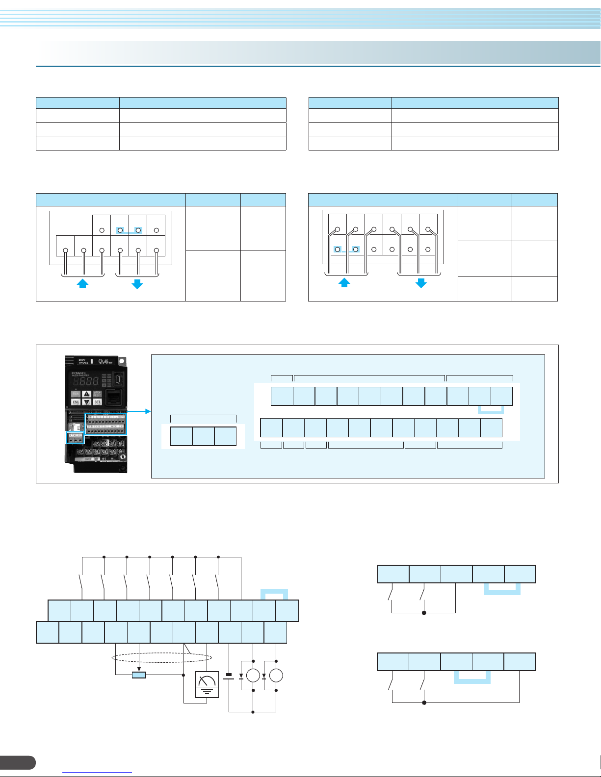
Terminal (
Stöwer Antriebstechnik GmbH, Enneststrasse 3, 51702 Bergneustadt, tel: 02261-40970, Fax: 02261-41309
Arrangements / Functions
Terminal Description
Symbol Terminal Name
R/L1, S/L 2, T/L3 Main power supply input terminals
U/T1, V/T2, W/T3 Inver ter output terminals
PD/+1, P/+ DC reactor connection terminals
Terminal Arrangement and Screw Diameter
Terminal Model
Screw Diameter
)
Symbol Terminal Name
P/+, RB External braking resistor connection terminals
P/+, N/- External braking unit connection terminals
G Ground connection terminal
Terminal Model
Screw Diameter
RB
PD/+1
P/+ N/-
R/L1 S/L2 T/L3 U/T1 V/T2 W/T3
001 – 007LF
001 – 004SF
M3.5
015 – 037LF
007– 022SF
Power input Output to motor
004 –040HF
Terminal Arrangement of Control Circuit Terminals
Relay contacts
AL2 AL1 AL0
M4
RS-485
comm.
R/L1 S/L2
PD/+ P/+
Power input Output to motor
RS-485
comm.
SN
7 6 5 4 3 2 1 L PLC P24
SP
EO EA H O OI L AM CM2 12 11
Pulse
Pulse
Train
Train
output
input
T/L3 U/T1 V/T2 W/T3
N/-
RB G G
Logic inputs
Analog input A nalog output Logic outputs
055 – 075LF
055 – 075HF
110LF
110 – 150HF
150 LF M8
Logic common
and power supply
M5
M6
Short bar
Wiring sample of control logic terminal (Sink logic)
Sink /source logic of intelligent input terminals
Sink or source logic is switched by a short bar as below.
Sink logic
Short bar
(Sink logic)
SN 7 6 5 4 3 2 1 L PLC P24
SP EO EA H O OI L AM CM2 12 11
Variable resistor
for freq. set tting
(1kΩ –2kΩ)
10
Freq. meter
(27Vdc 50m A max.)
RYRY
Source logic
2 1 L PLC P24
Short bar
2 1 L PLC P24
Short bar
 Loading...