

Page 1

Diesel Injection Pump
SERVICE MANUAL
New Common Rail System for HINO
E13C Type Engine
OPERATION
February, 2004
00400061E
Page 2

TABLE OF CONTENTS
1. Outline . . . . . . . . . . . . . . . . . . . . . . . . . . . . . . . . . . . . . . . . . . . . . . . . . . . . . . . . . . . . . . . . . . . . . . . . . . . . . . . . . . . . . . . . . . . . . . . 1
1-1. Product Application . . . . . . . . . . . . . . . . . . . . . . . . . . . . . . . . . . . . . . . . . . . . . . . . . . . . . . . . . . . . . . . . . . . . . . . . . . . . . . . . 1
1-2. Outline . . . . . . . . . . . . . . . . . . . . . . . . . . . . . . . . . . . . . . . . . . . . . . . . . . . . . . . . . . . . . . . . . . . . . . . . . . . . . . . . . . . . . . . . . . . 1
2. Outline of The Main New Features . . . . . . . . . . . . . . . . . . . . . . . . . . . . . . . . . . . . . . . . . . . . . . . . . . . . . . . . . . . . . . . . . . . . . . . . 2
2-1. Common Rail Specifications and Engine Features . . . . . . . . . . . . . . . . . . . . . . . . . . . . . . . . . . . . . . . . . . . . . . . . . . . . . . 2
2-2. System Construction . . . . . . . . . . . . . . . . . . . . . . . . . . . . . . . . . . . . . . . . . . . . . . . . . . . . . . . . . . . . . . . . . . . . . . . . . . . . . . . 3
3. Outline of Changes in Main Functional Parts . . . . . . . . . . . . . . . . . . . . . . . . . . . . . . . . . . . . . . . . . . . . . . . . . . . . . . . . . . . . . . . 4
3-1. Supply Pump . . . . . . . . . . . . . . . . . . . . . . . . . . . . . . . . . . . . . . . . . . . . . . . . . . . . . . . . . . . . . . . . . . . . . . . . . . . . . . . . . . . . . 4
3-2. Rail . . . . . . . . . . . . . . . . . . . . . . . . . . . . . . . . . . . . . . . . . . . . . . . . . . . . . . . . . . . . . . . . . . . . . . . . . . . . . . . . . . . . . . . . . . . . . . 5
3-3. Injector . . . . . . . . . . . . . . . . . . . . . . . . . . . . . . . . . . . . . . . . . . . . . . . . . . . . . . . . . . . . . . . . . . . . . . . . . . . . . . . . . . . . . . . . . . 6
3-4. Sensors (Only sensors that were changed.) . . . . . . . . . . . . . . . . . . . . . . . . . . . . . . . . . . . . . . . . . . . . . . . . . . . . . . . . . . . 10
3-5. ECU . . . . . . . . . . . . . . . . . . . . . . . . . . . . . . . . . . . . . . . . . . . . . . . . . . . . . . . . . . . . . . . . . . . . . . . . . . . . . . . . . . . . . . . . . . . . 12
3-6. Various Types of Control . . . . . . . . . . . . . . . . . . . . . . . . . . . . . . . . . . . . . . . . . . . . . . . . . . . . . . . . . . . . . . . . . . . . . . . . . . . 12
4. Diagnosis . . . . . . . . . . . . . . . . . . . . . . . . . . . . . . . . . . . . . . . . . . . . . . . . . . . . . . . . . . . . . . . . . . . . . . . . . . . . . . . . . . . . . . . . . . . 13
4-1. DTC (Diagnostic Trouble Code) Table . . . . . . . . . . . . . . . . . . . . . . . . . . . . . . . . . . . . . . . . . . . . . . . . . . . . . . . . . . . . . . . . 13
Page 3
1. Outline
1-1. Product Application
A. Application
Manufacturer Engine Model Destination
HINO E13C General countries
B. System Components Parts Number
Parts Name DENSO Parts Number
Supply pump 094000-0421 22730-1231A HP0 type
Injector 095000-5223 23910-1242A With QR code
Rail 095440-0460 22760-1150A
Engine ECU 102758-3001 89560-6530A With EDU inside
Accelerator position sensor 198300-8160 89441-6950A
Crankshaft position sensor 029600-0570 89411-1280A
Cylinder recognition sensor 949979-1300 — Included in the supply pump
Fuel temperature sensor 179730-0090 22790-1010A
Coolant temperature sensor 071560-0110 83420-1250A
Intake air temperature sensor 072800-0350 89441-6230A
Intake air pressure sensor 079800-5890 89390-1080A
Manufacturer Parts
Number
Remarks
1-2. Outline
•
This Service Manual describes the new common rail system installed on the E13C engine of large Hino trucks. The big-
gest difference compared with conventional common rail systems is that it uses an injector with a QR code. The basic
construction and operation of the system is about the same as for systems installed on the P11C engine, so this Service
Manual will only give a general outline of the E13C system and describe its unique features. For details on the common
rail system, refer to Service Bulletin ECD 01-08 "New Common Rail System (ECD-U2) for HINO" published in December
2001, and Service Manual "Common Rail System for HINO J05D/J08E Type Engine" published in October 2003.
-1-
Page 4
2. Outline of The Main New Features
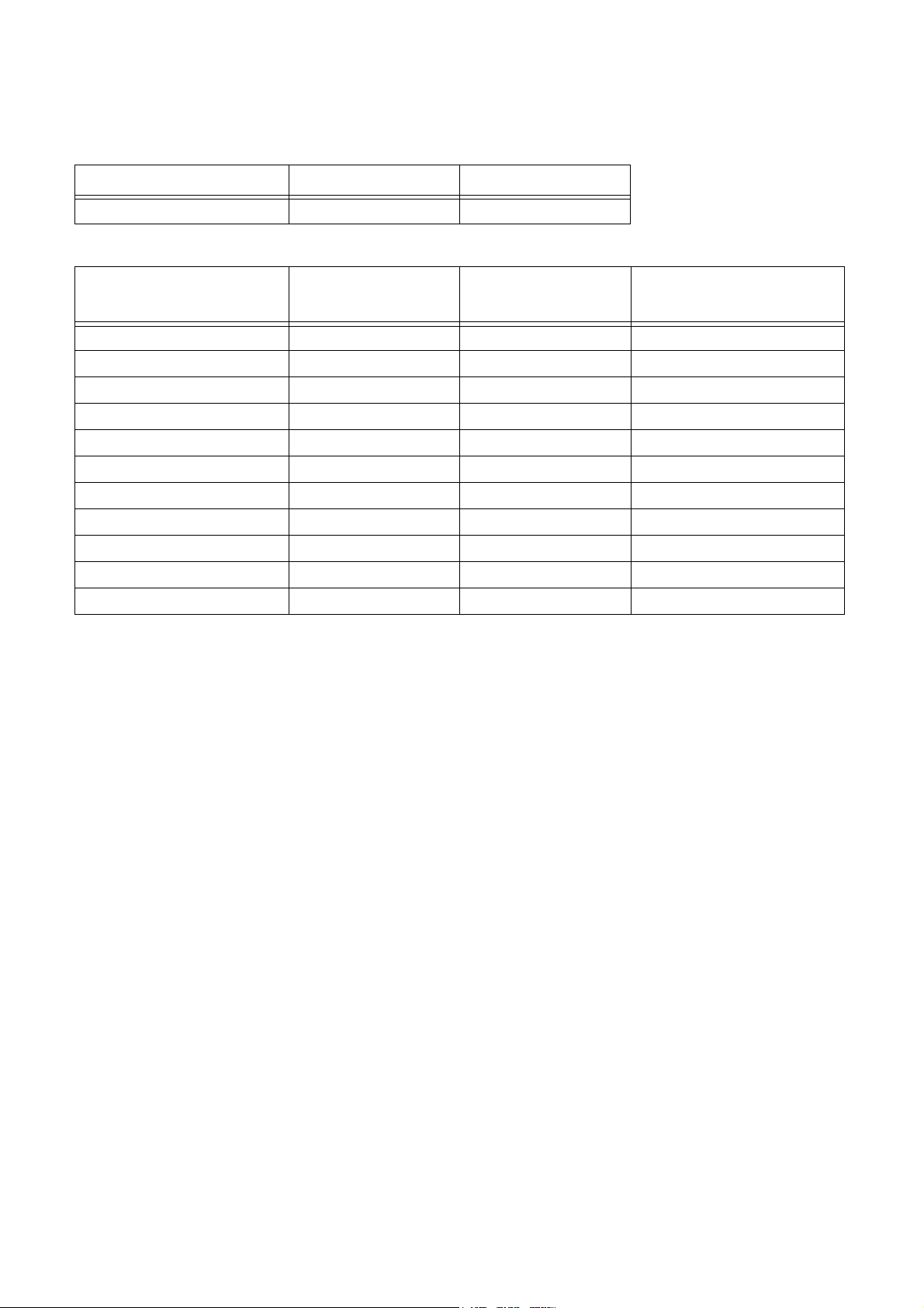
2-1. Common Rail Specifications and Engine Features
E13C K13C (Current Model)
Common Rail
Specifications
Engine Features
Main Features HP-0 + G2 HP-0 + X1
Pressure 160 MPa 120 MPa
Type L6, TI, 4 valves L6, TI, 4 valves
Displacement 13 L 13 L
Variation 5 Output Settings Low Output High Output
Output 265-382 kW/1800-2200 rpm 272 kW/2000 rpm 294 kW/2000 rpm
Torque 1764-2156 N•m/900 rpm
Vehicle Cargo and Dump Trucks, Tractors Cargo and Dump Trucks, Tractors
1520 N•m/1100 rpm 1667 N•m/1100 rpm
-2-
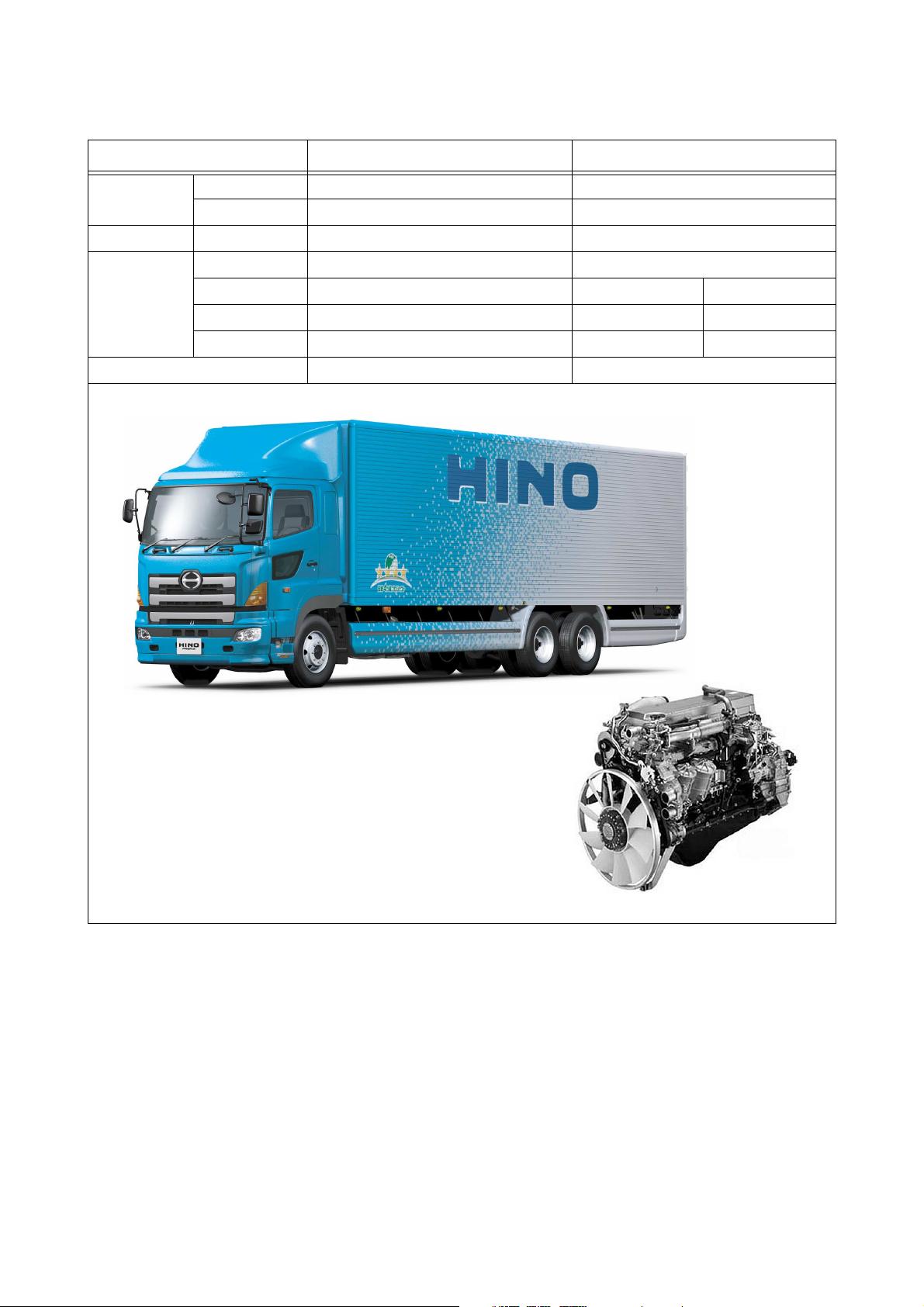
E13C Engine
Q000649E
Page 5
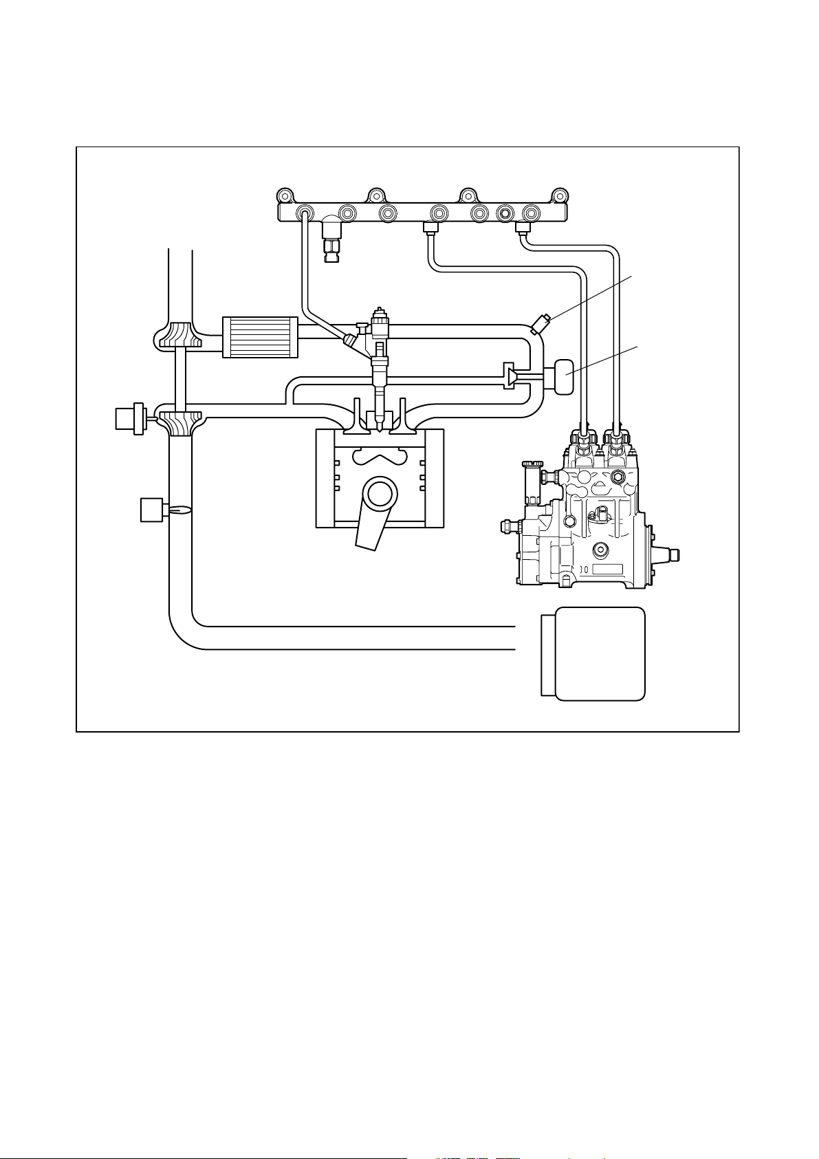
2-2. System Construction
< NOTE >
• For details on sensors such as the NE sensor and G sensor (sub-NE sensor), refer to Page 3,4 in Service Bulletin 01-08.
Rail
Intake air pressure
sensor
VNT actuator
Exhaust brake
actuator
Intercooler
G2 injector
EGR valve
HP-0 pump
ECU & EDU
-3-
Q000650E
Page 6
3. Outline of Changes in Main Functional Parts
Only the functional parts with significant changes are described.
3-1. Supply Pump
A. Changes
The items that have changed significantly are shown in the table below.
Item Conventional System New System Reason for Change
Installation method Saddle type Flange type Easier installation
Driving method Coupling Gear Easier installation
G sensor MPU MRE Reduced cost
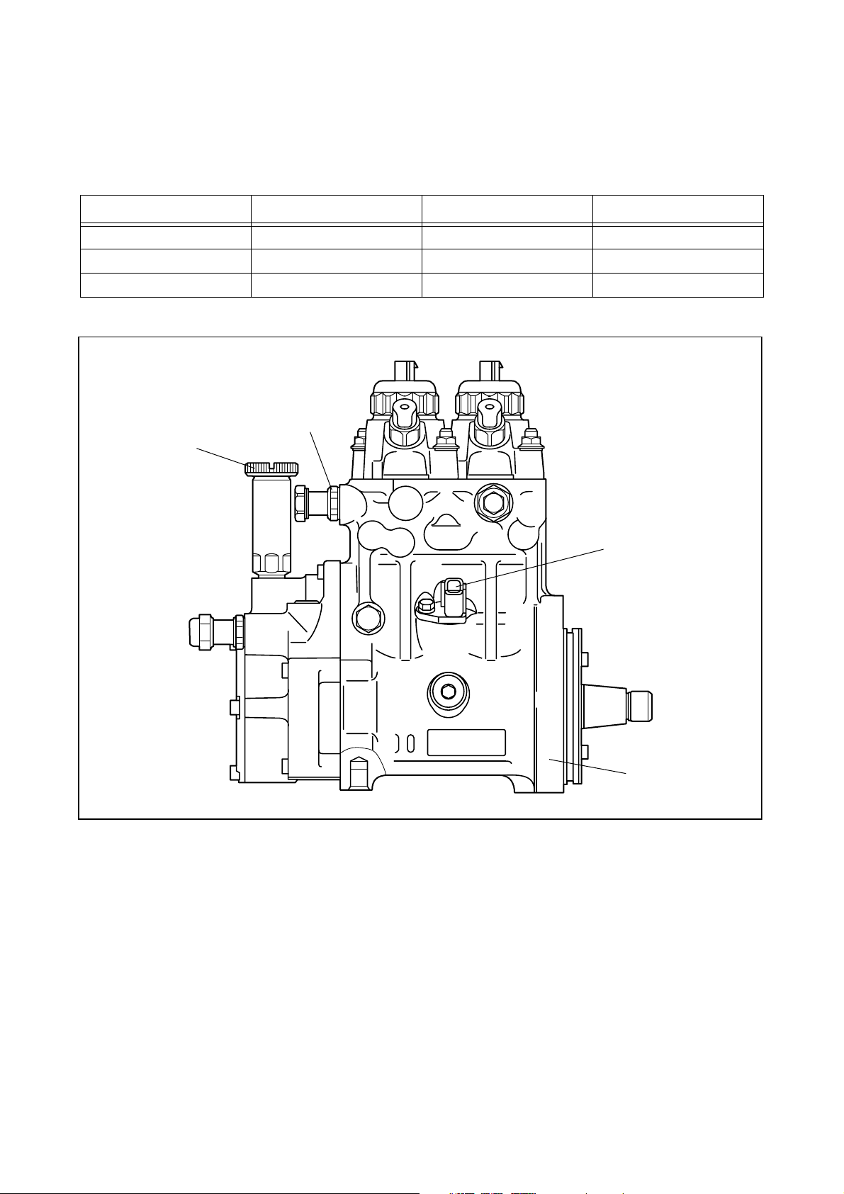
B. Construction
Air bleeder
Priming pump
G (sub-NE) sensor
Flange installation
C. Operation
For details on the operation, refer to page 12 - 15 in Service Manual "Common Rail System for HINO J05D/J08E Type
Engine".
Q000639E
-4-
Page 7
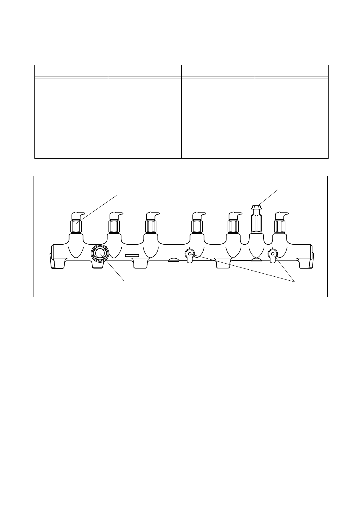
3-2. Rail
A. Changes
The items that have changed significantly are shown in the table below.
Item Conventional System New System Reason for Change
System pressure 120 MPa 160 MPa Improves performance
Highest pressure during
normal use
Pressure limiter valve open-
ing pressure
PC sensor specification 180 MPa 120 MPa To deal with the system
Installation position Outside engine head Inside engine head Easier installation
130 MPa 176 MPa Improves performance
140 ± 5 MPa 200 ± 9 MPa To deal with the system
pressure
pressure
B. Construction
Pressure limiter
Flow damper
PC sensor
C. Operation
For details on construction and operation, refer to page 10 in Service Bulletin 01-08.
Fuel inlet
Q000640E
-5-
Page 8

3-3. Injector
A. Changes
• Uses a compact and power-saving TWV (Two-Way Valve) for electromagnetic control of the injector.
• Conventional systems use adjusted resistance to correct the injection volume, but to improve the accuracy of correction,
the new system uses a QR (Quick Response) code. The QR code greatly increases the correction points of the injection
volume, improving correction accuracy. The properties of the engine cylinders are made more equal than before, which
increases fuel efficiency and decreases exhaust gas emissions. The ID code (30 base 16 characters) for injection volume
correction information is stamped on the injector head.
B. Construction
Cover
High pressure fuel
(from the rail)
Command piston
Nozzle spring
'
'
'
#
#
#
$
'
%
%
'
'
$
$
QR code
With cover removed
30 base 16 characters
Cover (With cover in place)
Solenoid valve
Control chamber
Pressure pin
Nozzle needle
Seat
Leak passage
High pressure fuel
Q000641E
-6-
Page 9

C. Operation
The TWV (solenoid valve) controls the pressure in the chamber by opening and closing the outlet orifice passage, which
in turn controls the start and end of injection.
a. When not injecting
When the solenoid is not energized, the outlet orifice passage is closed by the downward force of the TWV (solenoid
valve) spring. From this, the control chamber pressure trying to push down the command piston and the pressure trying
to push up the nozzle needle is the same. The differences in the areas receiving pressure and the force of the nozzle
spring closes the nozzle needle, so there is no injection.
b. During injection
When the solenoid is energized, the TMV (solenoid valve) is pulled up by the force of the solenoid, which opens the outlet
orifice, discharging the fuel from the control chamber. When fuel is discharged, the pressure in the control chamber is
reduced, which pulls up the command piston. This raises the nozzle needle, and injection is started.
c. End of injection
As the solenoid continues to be energized, the nozzle reaches its maximum lift point, creating the maximum injection
rate. When the energization of the solenoid is turned OFF, the TWV (solenoid valve) lowers, closing the outlet orifice.
Because of this, fuel enters the control chamber from the inlet orifice, which increases the pressure. The makes the noz-
zle needle close abruptly, stopping the injection.
Solenoid
TWV
Outlet orifice
Inlet orifice
Command piston
Nozzle
No Injection
Actuating
current
Rail
Control chamber
pressure
Injection rate
Injection
Actuating
current
Control chamber
pressure
Injection rate
Actuating
current
Control chamber
pressure
Injection rate
End of Injection
QD0717E
-7-
Page 10

D. Servicing injectors with QR code (Reference)
When replacing the injector or engine ECU, a HINO diagnostic tool must be used to register ID code in the engine ECU.
< NOTE >
• If the ID code of the installed injector is not correctly registered, it could cause engine malfunctions such as rough idling
or noise.
a. QR code location
b. QR code correction points
Injection volume Q
Cover
'
'
'
#
#
#
$%
'%
'
'
$
$
QR code (9mm square)
ID code (30 base 16 characters)
Base 16 characters noting fuel injection quantity correction
information for market service use.
QR code
Pressure parameters
Q000642E
Actuating pulse width TQ
-8-
Q000468E
Page 11

c. When replacing the injector
"No correction resistance, cannot be detected electrically"
Replaced injector
d. When replacing the engine ECU
"No correction resistance, cannot be detected electrically"
Vehicle injectors
Engine ECU
* Injector ID code must be registered with the engine ECU
QD1536E
Replaced engine ECU
* Injector ID code must be registered with the engine ECU
QD1537E
-9-
Page 12

3-4. Sensors (Only sensors that were changed.)
A. G Sensor (Cylinder Recognition Sensor)
The G sensor is an MRE (electromagnetic resistance element) type. When the hole on the flywheel passes the sensor,
the electromagnetic resistance flowing through the sensor changes. This variation in current is amplified by the internal
IC circuit, and a signal is output to the engine ECU. A cylinder recognition pulsar is installed to the supply pump camshaft,
and a cylinder recognition signal is output. 7 pulses are output for every revolution of the supply pump, or for every 2
revolutions of the engine. Cylinder recognition is inferred by combining the NE signal and the G signal. The irregular 7th
pulse is used to recognize the first cylinder.
a. External View and Terminal Positions
The MRE type differs to the conventional type in that a pulse of constant amplification is generated so that the OUT ter-
minal does not affect engine speed changes when constant amplitude (5V) is applied to the VCC.
OUT
G (sub-NE) Sensor
GND
VCC
VCC
GND
OUT
b. Output Signal
The OUT terminal outputs the following in synchronization with the pulsar missing teeth (pump camshaft). For each one
rotation of the pump camshaft, there are 6 pulses at 60° intervals, and 1 extra pulse used for recognition of the number
one cylinder.
approx. 5V
approx. 1V
0V
Q000738E
15° 60° 60° 60° 60° 60°
-10-
Q000739E
Page 13

c. NE/G Sensor wiring diagram
VCC
ECU
VCC
d. NE/G pulse chart
0°CA 120°CA 240°CA 360°CA 480°CA 600°CA 720°CA
NE+
(NE- standard)
G
(G-GND standard)
11 12 13 14 15 16 17 18 19 20 21 22 23 24 25 26 27 28 29 30 31 32 33 34 35 36 37 38 39 40 41 42 43 44 45 46 47 48 49 50 51 52 53 54 55 56 1 2 3 4 5 6 7 8 9 10 11 12 13 14 15 16 17 18 19 20 21 22 23 24 25 26 27 28 29 30 31 32 33 34 35 36 37 38 39 40 41 42 43 44 45 46 47 48 49 50 51 52 53 54 55 56
G
Input circuit
GND
NE
Input circuit
GND
#5TDC
78°CA 78°CA 78°CA 78°CA 78°CA 78°CA
#3TDC
4h missing tooth
3°CA
#6TDC
3°CA
#2TDC
Extra tooth
#4TDC
1 2 3 4 5 6 7 8 9 10 11 12 13 14 15
30°CA
Q000643E
#1TDC
The angle TDC (top dead center) is the engine piston top dead center of compression.
Q000740E
-11-
Page 14

B. Accelerator Sensor
The accelerator sensor is a non-contact type. It is linked to the movement of the accelerator pedal, which rotates the
lever, and the voltage of the output terminal changes according to the rotational position of the lever. There are hole el-
ements on the sensor. A magnet is installed on the shaft, which moves together with the accelerator pedal, so the mag-
netic field changes with the rotation of the shaft. A voltage is generated from these changes in the magnetic field.
VCVA VA SIDL EC
Sensor ECU
Hole elements (×2)
Amp
No.1
Amp
Magnets
LED
No.2
Light screen
Photo
IC
VC
VA
VAS
IDL
EC
S/W
Output Voltage (V)
VC
+5V
VA
VAS
IDL
EC
4.0
2.0
1.05
0
0- 42
Accelerator Position (%)
10050
Q000741E
3-5. ECU
• The ECU has 32 bits, compared to the 16 bits of conventional systems, so processing is faster. As in previous systems,
it is integrated with the EDU.
A. ECU External Wiring Diagram
B. ECU Connector Diagram
< NOTE >
• For the above details, refer to page 44 - 47 in Service Manual "Common Rail System for HINO J05D/J08E Type Engine",
published in October 2003.
3-6. Various Types of Control
< NOTE >
• Refer to page 20 - 24 in Service Bulletin ECD 01-08.
3.5
-12-
Page 15

4. Diagnosis
4-1. DTC (Diagnostic Trouble Code) Table
• A HINO PC tester can be used at the HINO dealership to display DTCs and perform diagnostic troubleshooting on the
significantly changed items. The DTCs (to be dealt with at the HINO dealership) are shown below for reference.
DTC P_Code DST-1 display Code explanation Reference
31 P0047 VNT solenoid valve 1 malfunction VNT solenoid valve 1 is abnormal. There could
be a solenoid valve malfunction, harness open
circuit, or ground short.
31 P0048 VNT solenoid valve 1 malfunction VNT solenoid valve 1 is abnormal. There could
be a harness +B short.
39 P0049 Turbo speed overrun An abnormally high turbo speed is detected. Detected by turbine
rotation sensor
76 P0088 Abnormally high rail pressure An abnormally high fuel pressure is detected.
78 P0093 Fuel leak There could be a fuel leak. Perform a fuel leak
check.
88 P0096 EGR valve seizure malfunction The EGR system is abnormal Valve is detected
18 P0097 EGR gas temperature sensor
malfunction (LO)
18 P0098 EGR gas temperature sensor
malfunction (HI)
17 P0102 Air flow sensor malfunction (LO) The air flow sensor is abnormal. There could
17 P0103 Air flow sensor malfunction (HI) The air flow sensor is abnormal. There could
37 P0108 Boost pressure sensor malfunc-
tion (HI)
16 P0112 Intake air temperature sensor
malfunction (LO)
16 P0113 Intake air temperature sensor
malfunction (HI)
11 P0117 Coolant temperature sensor mal-
function (LO)
Cannot detect the temperature normally.
There could be a sensor malfunction or a har-
ness ground short.
Cannot detect the temperature normally.
There could be a sensor malfunction, harness
open circuit or +B short.
be a sensor malfunction, harness open circuit
or GND short.
be a sensor malfunction or a harness +B short.
Cannot detect the boost pressure normally.
There could be a sensor malfunction or har-
ness short.
Cannot detect the temperature normally.
There could be a sensor malfunction or a har-
ness ground short.
Cannot detect the temperature normally.
There could be a sensor malfunction, harness
open circuit or +B short.
Cannot detect the temperature normally.
There could be a sensor malfunction or a har-
ness ground short.
Conventional pump
cannot pump (fuel
discharge)
through EGR gas
temperature to have
seized in the fully
closed position
Air flow sensor inter-
nal sensor
Air flow sensor inter-
nal sensor
-13-
Page 16

DTC P_Code DST-1 display Code explanation Reference
11 P0118 Coolant temperature sensor mal-
function (HI)
14 P0187 Fuel temperature sensor mal-
function (LO)
14 P0188 Fuel temperature sensor mal-
function (HI)
67 P0191 Rail pressure sensor malfunction Cannot detect the rail pressure normally.
67 P0192 Rail pressure sensor malfunction
(LO)
67 P0193 Rail pressure sensor malfunction
(HI)
59 P0200 ECU charge circuit fault (HI) The voltage for actuating the injector is too
51 P0201 Injector 1 open circuit There could be an injector 1 malfunction or
Cannot detect the temperature normally.
There could be a sensor malfunction, harness
open circuit or +B short.
Cannot detect the temperature normally.
There could be a sensor malfunction or a har-
ness ground short.
Cannot detect the temperature normally.
There could be a sensor malfunction, harness
open circuit or +B short.
There could be a sensor malfunction.
Cannot detect the rail pressure normally.
There could be a sensor malfunction or har-
ness ground short.
Cannot detect the rail pressure normally.
There could be a sensor malfunction, harness
open circuit or +B short.
high. Replace the ECU.
harness open circuit.
Leakage tempera-
ture
Leakage tempera-
ture
Characteristic
abnormality
52 P0202 Injector 2 open circuit There could be an injector 2 malfunction or
harness open circuit.
53 P0203 Injector 3 open circuit There could be an injector 3 malfunction or
harness open circuit.
54 P0204 Injector 4 open circuit There could be an injector 4 malfunction or
harness open circuit.
55 P0205 Injector 5 open circuit There could be an injector 5 malfunction or
harness open circuit.
56 P0206 Injector 6 open circuit There could be an injector 6 malfunction or
harness open circuit.
6 P0217 Overheating Overheating is detected. Inspect the cooling
system.
7 P0219 Engine overrun The engine speed is above the rated value.
34 P0234 Turbo over boost The boost pressure is higher than the stan-
dard.
37 P0237 Boost pressure sensor malfunc-
tion
Cannot detect the intake air pressure normally.
There could be a sensor malfunction, harness
open circuit or short.
-14-
Page 17

DTC P_Code DST-1 display Code explanation Reference
61 P0263 Cylinder correction error #1 The speed variations of the first cylinder are
larger than those of the other cylinders. The
flow damper could be operating.
62 P0266 Cylinder correction error #2 The speed variations of the second cylinder
are larger than those of the other cylinders.
The flow damper could be operating.
63 P0269 Cylinder correction error #3 The speed variations of the third cylinder are
larger than those of the other cylinders. The
flow damper could be operating.
64 P0272 Cylinder correction error #4 The speed variations of the fourth cylinder are
larger than those of the other cylinders. The
flow damper could be operating.
Conventional prod-
uct flow damper
operation judgment
and new speed vari-
ation judgment
Conventional prod-
uct flow damper
operation judgment
and new speed vari-
ation judgment
Conventional prod-
uct flow damper
operation judgment
and new speed vari-
ation judgment
Conventional prod-
uct flow damper
operation judgment
and new speed vari-
ation judgment
65 P0275 Cylinder correction error #5 The speed variations of the fifth cylinder are
larger than those of the other cylinders. The
flow damper could be operating.
66 P0278 Cylinder correction error #6 The speed variations of the sixth cylinder are
larger than those of the other cylinders. The
flow damper could be operating.
13 P0335 NE sensor malfunction Cannot detect the pulses from the NE sensor.
There could be a sensor malfunction or har-
ness abnormality.
12 P0340 G sensor malfunction Cannot detect the pulses from the G sensor.
There could be a sensor malfunction or har-
ness abnormality.
88 P0401 Insufficient EGR rate The EGR system is abnormal. The EGR rate
is lower than the standard value.
Conventional prod-
uct flow damper
operation judgment
and new speed vari-
ation judgment
Conventional prod-
uct flow damper
operation judgment
and new speed vari-
ation judgment
This code is also
output if both the NE
and G sensors are
malfunctioning
Valve is detected
through Air flow sen-
sor to have seized in
the fully closed posi-
tion
-15-
Page 18

DTC P_Code DST-1 display Code explanation Reference
88 P0402 Excessive EGR rate The EGR system is abnormal. The EGR rate
is higher than the standard value.
81 P0489 EGR solenoid valve 1 malfunc-
tion
81 P0490 EGR solenoid valve 1 malfunc-
tion
21 P0500 Vehicle speed sensor malfunction
(LO)
21 P0501 Vehicle speed sensor malfunction
(HI)
42 P0510 Idling switch malfunction The idling switch is not functioning normally.
EGR solenoid valve 1 is abnormal. There
could be a solenoid valve malfunction, har-
ness open circuit or ground short.
EGR solenoid valve 1 is abnormal. There
could be a solenoid valve malfunction or +B
harness short
Cannot detect the pulses from the vehicle
speed sensor. There could be a sensor mal-
function or harness abnormality.
The pulses from the vehicle speed sensor are
abnormal. There could be a sensor malfunc-
tion or harness abnormality.
While monitoring the vehicle conditions, check
the ON/OFF judgment.
Valve is detected
through Air flow sen-
sor to have seized in
the fully open posi-
tion
Open circuit
Noise
25 P0540 Pre-heat device malfunction The intake heater relay is abnormal. There
could be a relay malfunction or harness abnor-
mality.
97 P0545 Exhaust temperature sensor 1
malfunction (LO)
97 P0546 Exhaust temperature sensor 1
malfunction (HI)
3 P0605 Flash ROM abnormality ECU internal malfunction. Please replace the
3 P0606 CPU malfunction (hardware
detection)
3 P0907 CPU surveillance IC malfunction ECU internal malfunction. Please replace the
59 P0611 ECU charge circuit fault The voltage for actuating the injector is too
45 P0617 Starter switch malfunction The starter switch has shorted. While monitor-
73 P0628 Supply pump solenoid valve 1
malfunction
Cannot detect the temperature normally.
There could be a sensor malfunction or a har-
ness ground short.
Cannot detect the temperature normally.
There could be a sensor malfunction, harness
open circuit or +B short.
ECU.
ECU internal malfunction. Please replace the
ECU.
ECU.
low. Replace the ECU.
ing the vehicle conditions, check the ON/OFF
judgment.
The supply pump solenoid valve 1 has a volt-
age abnormality. There could be an open cir-
cuit or ground short.
PCV1, PCV1 &
PCV2 (large)
-16-
Page 19

DTC P_Code DST-1 display Code explanation Reference
73 P0629 Supply pump solenoid valve 1
malfunction
5 P0686 Main relay malfunction The main relay cannot be switched OFF.
41 P0704 Clutch switch malfunction Cannot detect the clutch switch normally.
47 P0850 Neutral switch malfunction Cannot detect the neutral switch normally.
32 P1062 VNT solenoid valve 2 malfunction VNT solenoid valve 2 is abnormal. There cold
32 P1063 VNT solenoid valve 2 malfunction VNT solenoid valve 2 is abnormal. There could
33 P1067 VNT solenoid valve 3 malfunction VNT solenoid valve 3 is abnormal. There cold
33 P1068 VNT solenoid valve 3 malfunction VNT solenoid valve 3 is abnormal. There could
38 P1071 Turbo speed sensor malfunction
(HI)
38 P1072 Turbo speed sensor malfunction
(LO)
23 P1132 Operation accelerator sensor
(LO)
23 P1133 Operation accelerator sensor (HI) Cannot detect the operation accelerator sen-
44 P1142 Idling volume (LO) Cannot detect the idling volume normally.
44 P1143 Idling volume (HI) Cannot detect the idling volume normally.
57 P1211 Injector common 1 malfunction There could be a ground short. Check the
The supply pump solenoid valve 1 has a volt-
age abnormality. There could be a +B short.
Inspect the relay.
While monitoring the vehicle conditions, check
the ON/OFF judgment.
While monitoring the vehicle conditions, check
the ON/OFF judgment.
be a solenoid valve malfunction, harness open
circuit, or ground short.
be a solenoid valve malfunction or harness +B
short.
be a solenoid valve malfunction, harness open
circuit, or ground short.
be a solenoid valve malfunction or harness +B
short.
The pulses from the turbine speed sensor are
abnormal. There could be a sensor malfunc-
tion or harness abnormality.
Cannot detect the pulses from the turbo speed
sensor. There could be a sensor malfunction
or harness abnormality.
Cannot detect the operation accelerator sen-
sor normally. Check the sensor voltage. There
could be an open circuit or a ground short.
sor normally. Check the sensor voltage. There
could be a +B short.
Check the sensor voltage. There could be an
open circuit or a ground short.
Check the sensor voltage. There could be a
+B short.
injector and the wiring.
PCV1, PCV1 &
PCV2 (large)
-17-
Page 20

DTC P_Code DST-1 display Code explanation Reference
57 P1212 Injector common 1 malfunction There could be an open circuit or +B short.
Check the injector and the wiring.
58 P1214 Injector common 2 malfunction There could be a ground short. Check the
injector and the wiring.
58 P1215 Injector common 2 malfunction There could be an open circuit or +B short.
Check the injector and the wiring.
76 P1229 Supply pump excessive pumping An abnormally high fuel pressure is detected.
Inspect the pump system.
77 P1266 Supply pump pumping fault An abnormally high fuel pressure is detected.
Inspect the pump system.
82 P1402 EGR solenoid valve 2 malfunc-
tion
82 P1403 EGR solenoid valve 2 malfunc-
tion
83 P1407 EGR solenoid valve 3 malfunc-
tion
83 P1408 EGR solenoid valve 3 malfunc-
tion
84 P1412 Pulse EGR solenoid valve mal-
function
EGR solenoid valve 2 is abnormal. There
could be a solenoid valve malfunction, har-
ness open circuit or ground short.
EGR solenoid valve 2 is abnormal. There
could be a solenoid valve malfunction or har-
ness +B short.
EGR solenoid valve 3 is abnormal. There
could be a solenoid valve malfunction, har-
ness open circuit or ground short.
EGR solenoid valve 3 is abnormal. There
could be a solenoid valve malfunction or har-
ness +B short.
The pulse EGR solenoid valve is abnormal.
There could be a solenoid valve malfunction,
harness open circuit or ground short.
Conventional pumps
cannot pump or
pressure limiter
operation
84 P1413 Pulse EGR solenoid valve mal-
function
85 P1416 EGR cooler overheat Overheating of the EGR cooler is detected.
19 P1417 EGR cooler coolant temperature
sensor malfunction (LO)
19 P1418 EGR cooler coolant temperature
sensor malfunction (HI)
96 P1427 Exhaust pressure sensor mal-
function (LO)
The pulse EGR solenoid valve is abnormal.
There could be a solenoid valve malfunction or
harness +B short.
Inspect the EGR cooler.
Cannot detect the temperature normally.
There could be a sensor malfunction or a har-
ness ground short.
Cannot detect the temperature normally.
There could be a sensor malfunction, harness
open circuit or +B short.
Cannot detect the exhaust pressure normally.
There could be a sensor malfunction, harness
open circuit or ground short.
-18-
Page 21

DTC P_Code DST-1 display Code explanation Reference
96 P1428 Exhaust pressure sensor mal-
function (HI)
26 P1462 Engine retarder 1 malfunction Engine retarder solenoid valve 1 is abnormal.
26 P1463 Engine retarder 1 malfunction Engine retarder solenoid valve 1 is abnormal.
27 P1467 Engine retarder 2 malfunction Engine retarder solenoid valve 2 is abnormal.
27 P1468 Engine retarder 2 malfunction Engine retarder solenoid valve 2 is abnormal.
27 P1472 T/M retarder relay malfunction The T/M retarder relay is abnormal. There
Cannot detect the exhaust pressure normally.
There could be a sensor malfunction or har-
ness +B short.
There could be a solenoid valve malfunction,
harness open circuit or ground short.
There could be a solenoid valve malfunction or
harness +B short
There could be a solenoid valve malfunction,
harness open circuit or ground short.
There could be a solenoid valve malfunction or
harness +B short
could be a relay malfunction, harness open cir-
cuit or ground short.
#4 to #6 side
retarder
#4 to #6 side
retarder
#1 to #3 side
retarder
#1 to #3 side
retarder
T/M retarder relay
for interlocked cruise
control in large and
medium sized vehi-
cles
29 P1473 T/M retarder relay malfunction The T/M retarder relay is abnormal. There
could be a relay malfunction or harness +B
short.
46 P1530 Engine stop switch closing mal-
function
43 P1565 Cruise switch malfunction The cruise switch has an ON malfunction.
2 P1601 QR code malfunction The QR code is abnormal. Check the QR
48 P1676 PCS switch malfunction Cannot detect the PCS switch normally. While
28 P1681 Exhaust brake solenoid valve
malfunction
28 P1682 Exhaust brake solenoid valve
malfunction
The engine stop switch is malfunctioning, or
the wiring has shorted. While monitoring the
vehicle conditions, check the ON/OFF judg-
ment.
While monitoring the vehicle conditions, check
the ON/OFF judgment.
code.
monitoring the vehicle conditions, check the
ON/OFF judgment.
The exhaust brake solenoid valve is abnormal.
There could be a solenoid valve malfunction,
harness open circuit or ground short.
The exhaust brake solenoid valve is abnormal.
There could be a solenoid valve malfunction or
harness +B short.
T/M retarder relay
for interlocked cruise
control in large and
medium sized vehi-
cles
-19-
Page 22

DTC P_Code DST-1 display Code explanation Reference
91 P2002 DPF system malfunction The DPF system is abnormal. There could be
welding damage or clogging. Perform a DPF
system check.
98 P2032 Exhaust temperature sensor 2
malfunction (LO)
98 P2033 Exhaust temperature sensor 2
malfunction (HI)
Cannot detect the temperature normally.
There could be a sensor malfunction or a har-
ness ground short.
Cannot detect the temperature normally.
There could be a sensor malfunction, harness
open circuit or +B short.
22 P2120 Malfunction of both accelerator
sensors
22 P2121 Accelerator sensor 1 malfunction Cannot detect accelerator sensor 1 normally.
22 P2122 Accelerator sensor 1 malfunction
(LO)
22 P2123 Accelerator sensor 1 malfunction
(HI)
22 P2126 Accelerator sensor 2 malfunction Cannot detect accelerator sensor 2 normally.
22 P2127 Accelerator sensor 2 malfunction
(LO)
22 P2128 Accelerator sensor 2 malfunction
(HI)
15 P2228 Atmospheric pressure sensor
malfunction (LO)
15 P2229 Atmospheric pressure sensor
malfunction (HI)
72 P2633 Supply pump solenoid valve 2
malfunction
72 P2634 Supply pump solenoid valve 2
malfunction
Both accelerator sensor systems are malfunc-
tioning. There could be a sensor abnormality
or harness abnormality.
Check the sensor voltage.
Cannot detect accelerator sensor 1 normally.
Check the sensor voltage. There could be an
open circuit or ground short.
Cannot detect accelerator sensor 1 normally.
Check the sensor voltage. There could be a
+B short.
Check the sensor voltage.
Cannot detect accelerator sensor 2 normally.
Check the sensor voltage. There could be an
open circuit or ground short.
Cannot detect accelerator sensor 2 normally.
Check the sensor voltage. There could be a
+B short.
The atmospheric pressure sensor (inside the
ECU) is abnormal. If it occurs frequently, the
ECU must be repaired or replaced.
The atmospheric pressure sensor (inside the
ECU) is abnormal. If it occurs frequently, the
ECU must be repaired or replaced.
Supply pump solenoid valve 2 has abnormal
voltage. There could be an open circuit or
ground short.
Supply pump solenoid valve 2 has abnormal
voltage. There could be a +B short.
PCV2 for large vehi-
cles
PCV2 for large vehi-
cles
9 U0101 Communication obstruction
(transmission)
Communication with the transmission ECU is
obstructed.
-20-
Abnormal communi-
cation with AT-ECU
Page 23

DTC P_Code DST-1 display Code explanation Reference
9 U0104 Communication obstruction
(cruise)
9 U0121 Communication obstruction
(ABS)
9 U0132 Communication obstruction (air
suspension)
9 U0155 Communication obstruction
(meter)
9 U1001 CAN communication obstruction
(vehicle)
Communication with the vehicle cruise ECU is
obstructed.
Communication with the ABS ECU is
obstructed.
Communication with the air suspension ECU
is obstructed.
Communication with the meter ECU is
obstructed.
The communication with the other computers
installed in the vehicle is abnormal.
CAN communica-
tion bus OFF judg-
ment
-21-
 Loading...