

Page 1

MENU
FOREWORD
This workshop manual has been prepared to provide information regarding repair procedures on Hino Trucks.
Applicable for HINO 238, 258LP, 268, 338 series, equipped with J08E-VB and J08E-VC engine
When making any repairs on your vehicle, be careful not to be injured through improper procedures.
As for maintenance items, refer to the Driver’s / Owner’s Manual.
All information and specifications in this manual are based upon the latest product information available at the time of printing.
Hino Motors Sales U.S.A., Inc. reserves the right to make changes at any time without prior notice.
Please note that the publications below have also been prepared as relevant workshop manuals for the components and systems in these vehicles.
Manual Name Pub. No.
Chassis Workshop Manual S1-UNAE11A 2/2
J08E-VB, VC Engine Workshop Manual S5-UJ08E11A
S7-UNAE11A 1/3
Trouble Shooting Workshop Manual
S7-UNAE11A 2/3
S7-UNAE11A 3/3
Page 2

CHAPTER REFERENCES REGARDING THIS WORKSHOP MANUAL
Use this chart to the appropriate chapter numbers for servicing your particular vehicle.
MANUAL NO. S1-UNAE11A 1/2 (U.S.A.), S1-CNAE11A 1/2 (CANADA)
CHAPTER
GENERAL INTRODUCTION GN02-001
CLUTCH MAIN UNIT CL02-001 CL02-002
CLUTCH CONTROL CL03-001
TRANSMISSION MAIN UNIT TR02-001
AUTOMATIC TRANSMISSION
TRANSMISSION/TRANSFER CONTROL
PROPELLER SHAFT
DIFFERENTIAL CARRIER
BRAKE EQUIPMENT BR01-001 BR01-002
SERVICE BRAKE BR02-001 BR02-002
ABS (ANTI-LOCK BRAKE SYSTEM) BR03-001 BR03-002
EXHAUST BRAKE BR05-001
PARKING BRAKE BR07-001
MODELS HINO 238, 258LP, 268, 338, 358
Production Model
Code
TR04-001
TR06-001
NE8J, NF8J, NJ8J, NV8J
PP02-001
DF02-001
TR04-002
TR06-002
STEERING EQUIPMENT SR01-001
STEERING UNIT SR02-001
POWER STEERING SR03-001
FRONT AXLE AX02-001
REAR AXLE
WHEEL & TIRE AX04-001
SUSPENSION SU02-001
CHASSIS FRAME FC02-001
CAB CA02-001
ELECTRICAL EQUIPMENT EL01-001
ELECTRIC WIRE EL02-001
This manual does not contain items on half-tone dot meshing.
AX03-001
Page 3

INDEX: CHASSIS GROUP 1/4
GENERAL INTRODUCTION
CLUTCH EQUIPMENT
CLUTCH MAIN UNIT
WORKSHOP
MANUAL
CLUTCH CONTROL
TRANSMISSION EQUIPMENT
TRANSMISSION MAIN UNIT
TRANSFER MAIN UNIT
AUTOMATIC TRANSMISSION
PTO (POWER TAKE-OFF)
TRANSMISSION / TRANSFER CONTROL
PROPELLER SHAFT EQUIPMENT
PROPELLER SHAFT
DIFFERENTIAL EQUIPMENT
DIFFERENTIAL CARRIER
BRAKE EQUIPMENT
SERVICE BRAKE
ABS
Page 4

INDEX: CHASSIS GROUP 2/4
ES START (EASY & SMOOTH START) SYSTEM
EXHAUST BRAKE
RETARDER BRAKE
PARKING BRAKE
STEERING EQUIPMENT
STEERING UNIT
POWER STEERING
AXLE EQUIPMENT
FRONT AXLE
REAR AXLE
WHEEL & TIRE
SUSPENSION EQUIPMENT
SUSPENSION
CHASSIS EQUIPMENT
CHASSIS FRAME
COUPLER (5TH WHEEL)
PINTLE HOOK
Page 5

INDEX: CHASSIS GROUP 3/4
CAB EQUIPMENT
CAB
ELECTRICAL EQUIPMENT
ELECTRIC WIRE
HYBRID SYSTEM
Page 6

INDEX: CHASSIS GROUP 4/4
ENGINE CONTROL
FUEL CONTROL
BRAKE CONTROL
SUSPENSION CONTROL
CAB EQUIPMENT CONTROL
OTHERS
Page 7

GENERAL INTRODUCTION (CHASSIS) GN02–1
GN0 2
GENERAL INTRODUCTION (CHASSIS)
GENERAL INTRODUCTION.....................GN02-2
GENERAL PRECAUTIONS.............................GN02-2
IDENTIFICATION INFORMATION ...................GN02-5
HOW TO USE
THIS WORKSHOP MANUAL.........................GN02-12
PRECAUTIONS.............................................GN02-15
SEALANT ON THE TAPERED SCREW
FOR PIPING ..................................................GN02-18
NYLON TUBE REPLACEMENT METHOD ...GN02-19
METRIC INFORMATION ...............................GN02-21
SPECIFIED TORQUE
FOR STANDARD BOLTS AND NUTS ...........GN02-23
SPECIFIED TORQUE
FOR FLANGE BOLTS AND NUTS ................GN02-23
RECOMMENDED LUBRICANTS ..................GN02-25
VEHICLE LIFT
AND SUPPORT LOCATIONS........................GN02-27
INFORMATION DISPLAY ..............................GN02-29
SYMPTOM SIMULATION ..............................GN02-34
GLOSSARY ...................................................GN02-36
GLOSSARY OF SAE AND HINO TERMS.....GN02-39
GN02-001
Page 8

GENERAL INTRODUCTION (CHASSIS)GN02–2
GENERAL INTRODUCTION
GENERAL PRECAUTIONS
EN00Z00020100001
Some recommended and standard maintenance services for your vehicle are included in this section. When performing maintenance on your vehicle be careful not to get injured by improper work. Improper or incomplete work can cause a malfunction
of the vehicle which may result in personal injury and/or property damage. If you have any question about performing maintenance, please consult your Hino dealer.
WARNING
When working on your vehicle, observe the following general precautions to prevent death, personal injury and/or
property damage in addition to the particular DANGERS, WARNINGS, CAUTIONS and NOTICES in each chapter.
• Always wear safety glasses or goggles to protect your eyes.
• Remove rings, watches, ties, loose hanging jewelry and loose clothing before starting work on the vehicle.
• Bind long hair securely behind the head.
• When working on the vehicle, apply the parking brake firmly, place the gear shift lever in "Neutral" or "N" and
block the wheels.
• Always turn off the starter switch to stop the engine, unless the operation requires the engine running. Remov-
ing the key from the switch is recommended.
• To avoid serious burns, keep yourself away from hot metal parts such as the engine, exhaust manifold, radia-
tor, muffler, exhaust pipe and tail pipe.
• Do not smoke while working on the vehicle since fuel, and gas from battery are flammable.
• Take utmost care when working on the battery. It contains corrosive sulfuric acid.
• Large electric current flows through the battery cable and starter cable. Be careful not to cause a short which
can result in personal injury and/or property damage.
• Read carefully and observe the instructions specified on the jack before using it.
• Use safety stands to support the vehicle whenever you need to work under it. It is dangerous to work under a
vehicle supported only by a jack.
• If it is necessary to run the engine after the hood is raised (tilted), make sure that the parking brake is firmly
applied, the wheels are blocked, and the gear shift lever is positioned in "Neutral" before staring the engine.
• Run the engine only in a well-ventilated area to avoid inhalation of carbon monoxide.
• Keep yourself, your clothing and your tools away from moving parts such as the cooling fan and V-belts when
the engine is running.
• Be careful not to damage lines and hoses by stepping or holding your feet on them.
• Be careful not to leave any tool in the engine compartment. The tool may be hit by moving parts, which can
cause personal injury.
DEFINITION OF SAFETY TERMS
Indicates an extremely hazardous situation if proper procedures are not followed and could
result in death or serious injury.
Indicates a potential hazardous situation if proper procedures are not followed and could
result in death or serious injury.
Indicates a hazardous situation if proper procedures are not followed and could result in
serious injury or damage to parts/equipment.
Indicates the need to follow proper procedures and to pay attention to precautions so that
efficient service is provided.
Provides additional information to help you to perform the repair efficiently.
Page 9

GENERAL INTRODUCTION (CHASSIS) GN02–3
TOWING
• When being towed, always place the gear shift lever in "Neutral" and release the parking brake completely. In order to
protect the bumper, fit a protection bar against the lower edge of the bumper and put a wood block under the frame near
the No. 1 cross member when attaching the towing chain. Never lift or tow the vehicle if the chain is in direct contact with
the bumper.
1. Towing procedures
(1) Make sure that the propeller shaft of the vehicle to be towed is removed. When the differential gear or rear axle shaft is
defective, remove both right and left rear axle shafts, then cover the hub opening to prevent loss of axle lubricant and
entry of dirt or foreign matter.
(2) Use a heavy duty cable or rope when towing the vehicle. Fasten the cable securely to the towing hook on the frame.
(3) The angle of pulling direction of the cable fastened to the towing hook must not exceed 15 in horizontal and vertical
directions from the straight ahead, level direction. Avoid using the hook in a way that subjects it to jerk, as in towing a
vehicle trapped in a gutter.
(4) Keep the gear shift lever in Neutral.
(5) Make sure that the starter switch is kept in the "ON" position, if the engine is not running.
(6) Make sure that the engine of the towed vehicle is kept running. If the engine is off, no compressed air/ no vacuum will be
available for the brake. This is dangerous, as the brake system does not function if the engine is not running.
In addition, the power steering system will not function. The steering wheel, therefore, will become unusually hard to turn,
making it impossible to control the vehicle.
(7) Note that the engine brake and exhaust brake cannot be applied, if the propeller shaft is removed.
(8) Make a slow start to minimize shock. Towing speed should be less than 30 km/h {18 mile/h}.
2. If the engine of the towed vehicle is defective, make sure that the vehicle is towed only by a tow truck designed
for that purpose.
(1) Front end towing (with front wheels raised off the ground)
When towing from the front end with the front wheels raised off the ground, remove the rear axle shafts to protect the
transmission and differential gears from being damaged. The hub openings should be covered to prevent the loss of axle
lubricant or the entry of dirt or foreign matter. The above-mentioned precautions should be observed for vehicles
equipped with either manual or automatic transmission, and for even short distance towing. After being towed, check and
refill the rear axle housing with lubricant if necessary.
(2) Rear end towing
When being towed with the rear wheels raised off the ground, fasten and secure the steering wheel in a straight-ahead
position.
CLEAN AIR ACT
1. Heavy-duty engine rebuilding practices.
§ 86.004-40
• The provisions of this section are applicable to heavy-duty engines subject to model year 2004 or later standards and are
applicable to the process of engine rebuilding (or rebuilding a portion of an engine or engine system). The process of
engine rebuilding generally includes disassembly, replacement of multiple parts due to wear, and reassembly, and also
may include the removal of the engine from the vehicle and other acts associated with rebuilding an engine. Any deviation
from the provisions contained in this section is a prohibited act under section 203(a) (3) of the Clean Air Act (42 U.S.C.
7522(a) (3)).
(1) When rebuilding an engine, portions of an engine, or an engine system, there must be a reasonable technical basis for
knowing that the resultant engine is equivalent, from an emissions standpoint, to a certified configuration (i.e., tolerances,
calibrations, specifications) and the model year(s) of the resulting engine configuration must be identified. A reasonable
basis would exist if:
a. Parts installed, whether the parts are new, used, or rebuilt, are such that a person familiar with the design and func-
tion of motor vehicle engines would reasonably believe that the parts perform the same function with respect to emissions control as the original parts; and
b. Any parameter adjustment or design element change is made only:
In accordance with the original engine manufacturer's instructions; or
Where data or other reasonable technical basis exists that such parameter adjustment or design element change,
when performed on the engine or similar engines, is not expected to adversely affect in-use emissions.
(2) When an engine is being rebuilt and remains installed or is reinstalled in the same vehicle, it must be rebuilt to a configu-
ration of the same or later model year as the original engine. When an engine is being replaced, the replacement engine
must be an engine of (or rebuilt to) a configuration of the same or later model year as the original engine.
Page 10

GENERAL INTRODUCTION (CHASSIS)GN02–4
(3) At time of rebuild, emissions-related codes or signals from on-board monitoring systems may not be erased or reset with-
out diagnosing and responding appropriately to the diagnostic codes, regardless of whether the systems are installed to
satisfy requirements in § 86.004-25 or for other reasons and regardless of form or interface. Diagnostic systems must be
free of all such codes when the rebuilt engine is returned to service. Such signals may not be rendered inoperative during
the rebuilding process.
(4) When conducting a rebuild without removing the engine from the vehicle, or during the installation of a rebuilt engine, all
critical emissions-related components listed in § 86.004-25(2) not otherwise addressed by paragraphs (1) through (3) of
this section must be checked and cleaned, adjusted, repaired, or replaced as necessary, following manufacturer recommended practices.
(5) Records shall be kept by parties conducting activities included in paragraphs (1) through (4) of this section. The records
shall include at minimum the mileage and/or hours at time of rebuild, a listing of work performed on the engine and emissions-related control components including a listing of parts and components used, engine parameter adjustments, emissions-related codes or signals responded to and reset, and work performed under paragraph (4) of this section.
a. Parties may keep records in whatever format or system they choose as long as the records are understandable to an
EPA enforcement officer or can be otherwise provided to an EPA enforcement officer in an understandable format
when requested.
b. Parties are not required to keep records of information that is not reasonably available through normal business prac-
tices including information on activities not conducted by themselves or information that they cannot reasonably
access.
c. Parties may keep records of their rebuilding practices for an engine family rather than on each individual engine
rebuilt in cases where those rebuild practices are followed routinely.
d. Records must be kept for a minimum of two years after the engine is rebuilt.
2. Maintenance instructions.
§ 86.010-38
(1) For each new diesel-fueled engine subject to the standards prescribed in § 86.007-11, as applicable, the manufacturer
shall furnish or cause to be furnished to the ultimate purchaser a statement that
"This engine must be operated only with ultra low-sulfur diesel fuel (meeting EPA specifications for highway diesel fuel, including a 15 ppm sulfur cap)."
Page 11

GENERAL INTRODUCTION (CHASSIS) GN02–5
VIN
label
IDENTIFICATION INFORMATION
EN00Z00020200001
1. VEHICLE IDENTIFICATION NUMBER
• VEHICLE IDENTIFICATION NUMBER (VIN) is comprised of 17 digits and letters. The VIN label is affixed to the left pillar
of the cab.
These numbers are used for identification purposes when you have a vehicle registered or inspected. Please quote these
numbers when ordering spare parts or reporting technical matter to receive prompt service attention.
• The following is an explanation of the items that are listed on the VIN label.
Page 12

GENERAL INTRODUCTION (CHASSIS)GN02–6
(1) VIN
See VEHICLE IDENTIFICATION NUMBER (VIN) STRUCTURE on the following page.
(2) P.S. (PRODUCTION SERIES) AND VEHICLE COMPONENTS
MODEL
(CLASS)
HINO238
(6)
HINO258
(6)
PRODUC-
TION CODE
MODEL SERIES
CLUTCH
NE8J HBC -
GBC 350mm FS5406 9.01 5.27 3.22 2.04 1.36 1.00 8.63
NE8J
HBC
JBC 350mm FS5406 9.01 5.27 3.22 2.04 1.36 1.00 8.63
SIZE
TRANS-
MIS-
SION
SERIES
TRANSMISSION RATIO REAR
1st 2nd 3rd 4th 5th 6th Rev.
2200HS 3.10 1.81 1.41 1.00 0.71 0.61 4.49
2200RDS 3.10 1.81 1.41 1.00 0.71 0.61 4.49
2500RDS 3.51 1.90 1.44 1.00 0.74 0.64 5.09
- 2200HS 3.10 1.81 1.41 1.00 0.71 0.61 4.49
- 2200RDS 3.10 1.81 1.41 1.00 0.71 0.61 4.49
- 2500RDS 3.51 1.90 1.44 1.00 0.74 0.64 5.09
AXLE
SERIES
RS17-145
RS19-145
RS17-145
RS19-145
RS17-145
RS19-145
RS17-145
RS19-145
RS17-145
RS19-145
RS17-145
RS19-145
RS17-145
RS19-145
RS17-145
RS19-145
SERVICE
BRAKE
PARK-
ING
BRAKE
SUSPEN-
SION
HDLor
A
HDLor
A
FWA
HINO268
(6)
NJ8J
NE8J
- 2200HS 3.10 1.81 1.41 1.00 0.71 0.61 4.49
KBC
- 2200RDS 3.10 1.81 1.41 1.00 0.71 0.61 4.49
- 2500RDS 3.51 1.90 1.44 1.00 0.74 0.64 5.09
GBC 350mm FS5406 9.01 5.27 3.22 2.04 1.36 1.00 8.63
- 2200HS 3.10 1.81 1.41 1.00 0.71 0.61 4.49
HBC
- 2200RDS 3.10 1.81 1.41 1.00 0.71 0.61 4.49
- 2500RDS 3.51 1.90 1.44 1.00 0.74 0.64 5.09
RS17-145
RS19-145
RS17-145
RS19-145
RS17-145
RS19-145
RS17-145
RS19-145
RS17-145
RS19-145
RS17-145
RS19-145
RS17-145
RS19-145
FWLor
A
HDLor
A
Page 13

GENERAL INTRODUCTION (CHASSIS) GN02–7
MODEL
(CLASS)
HINO268
(6)
PRODUC-
TION CODE
MODEL SERIES
JBC 350mm FS5406 9.01 5.27 3.22 2.04 1.36 1.00 8.63
NJ8J
KBC
NBC 350mm FS6406 9.01 5.27 3.22 2.04 1.36 1.00 8.63
PBC
CLUTCH
SIZE
TRANS-
MIS-
SION
SERIES
TRANSMISSION RATIO REAR
1st 2nd 3rd 4th 5th 6th Rev.
- 2200HS 3.10 1.81 1.41 1.00 0.71 0.61 4.49
- 2200RDS 3.10 1.81 1.41 1.00 0.71 0.61 4.49
- 2500RDS 3.51 1.90 1.44 1.00 0.74 0.64 5.09
- 2500RDS 3.51 1.90 1.44 1.00 0.74 0.64 5.09
- 3000RDS 3.49 1.86 1.41 1.00 0.75 0.65 5.03
AXLE
SERIES
RS17-145
RS19-145
RS17-145
RS19-145
RS17-145
RS19-145
RS17-145
RS19-145
RS21-145
RS23-160
RS21-145
RS23-160
RS21-145
RS23-160
SER-
VICE
BRAKE
PARK-
ING
BRAKE
FW
SUSPEN-
SION
L
or
A
HINO268
(7)
HINO338
(7)
- 3500RDS 4.59 2.25 1.54 1.00 0.75 0.65 5.00
NV8J
TBC 350mm FS6406 9.01 5.27 3.22 2.04 1.36 1.00 8.63
- 2500RDS 3.51 1.90 1.44 1.00 0.74 0.64 5.09
SBC
- 3000RDS 3.49 1.86 1.41 1.00 0.75 0.65 5.03
- 3500RDS 4.59 2.25 1.54 1.00 0.75 0.65 5.00
DBC 350mm FS6406 9.01 5.27 3.22 2.04 1.36 1.00 8.63 RS21-145
NF8J
EBC - 2500RDS 3.51 1.90 1.44 1.00 0.74 0.64 5.09 RS21-145
NV8J NBC 350mm FS6406 9.01 5.27 3.22 2.04 1.36 1.00 8.63
RS21-145
RS23-160
RS21-145
RS23-160
RS21-145
RS23-160
RS21-145
RS23-160
RS21-145
RS23-160
RS21-145
RS23-160
FWLor
HD
or
FW
A
L
A
Page 14

GENERAL INTRODUCTION (CHASSIS)GN02–8
MODEL
(CLASS)
HINO338
(7)
PRODUC-
TION CODE
MODEL SERIES
PBC
NV8J
TBC 350mm FS6406 9.01 5.27 3.22 2.04 1.36 1.00 8.63
SBC
CLUTCH
SIZE
TRANS-
MIS-
SION
SERIES
TRANSMISSION RATIO REAR
1st 2nd 3rd 4th 5th 6th Rev.
- 2500RDS 3.51 1.90 1.44 1.00 0.74 0.64 5.09
- 3000RDS 3.49 1.86 1.41 1.00 0.75 0.65 5.03
- 3500RDS 4.59 2.25 1.54 1.00 0.75 0.65 5.00
- 2500RDS 3.51 1.90 1.44 1.00 0.74 0.64 5.09
- 3000RDS 3.49 1.86 1.41 1.00 0.75 0.65 5.03
- 3500RDS 4.59 2.25 1.54 1.00 0.75 0.65 5.00
AXLE
SERIES
RS21-145
RS23-160
RS21-145
RS23-160
RS21-145
RS23-160
RS21-145
RS23-160
RS21-145
RS23-160
RS21-145
RS23-160
RS21-145
RS23-160
SERVICE
BRAKE
PARK-
ING
BRAKE
FWLor
SUSPEN-
SION
A
NBC 350mm FS6406 9.01 5.27 3.22 2.04 1.36 1.00 8.63 RS23-160
PBC
HINO358
(8)
NH8J
TBC 350mm FS6406 9.01 5.27 3.22 2.04 1.36 1.00 8.63 RS23-160
SBC
CODE SERVICE BRAKE
H: Hydraulic
F: Full air
- 3000RDS 3.49 1.86 1.41 1.00 0.75 0.65 5.03 RS23-160
- 3500RDS 4.59 2.25 1.54 1.00 0.75 0.65 5.00 RS23-160
- 3000RDS 3.49 1.86 1.41 1.00 0.75 0.65 5.03 RS23-160
- 3500RDS 4.59 2.25 1.54 1.00 0.75 0.65 5.00 RS23-160
PARKING BRAKE CONTROL CODE
D: ACTING ON DIFFERENTIAL
W: ACTING ON REAR WHEEL
FWLor
A
FWLor
A
SUSPENSION
L: LEAF
A: AIR
Page 15

GENERAL INTRODUCTION (CHASSIS) GN02–9
HINO VEHICLE IDENTIFICATION NUMBER (VIN) STRUCTURE FOR U.S.A. and CANADA (2015MY)
WMI VDS CD VIS
12 3 4 56 78 9 10111213141516
5P V NJ 8 J T 4 F4S10 0 0
17
1
MANUFACTURER TYPE
MAKE, MODEL
LINE & CAB/BODY TYPE,
SERIES, BRAKE SYSTEM
MODEL YEAR
ASSEMBLY PLANT
ENGINE MODEL
WHEEL BASE
CHECK DIGIT
MODIFICATION
SEQUENTIAL NUMBER
CODE
JHA
JHB
TRUCK
INCOMPLETE VEHICLE
TYPEMANUFACTURER
HINO MOTORS, LTD.
HINO MOTORS, LTD.
5PV INCOMPLETE VEHICLE
HINO MOTORS
MANUFACTURING
U.S.A., INC.
2AY INCOMPLETE VEHICLE
HINO MOTORS
CANADA, LTD.
CODE
P
CODE
2023
YEARYEAR
R 2024
S 2025
T 2026L 2020
M 2021
N 2022
H 2017
J 2018
K 2019
F 2015
G 2016
CODE
8J
J08E-VC
MODEL
7.6 LITERS, DIESEL 220HP
J08E-VB 7.6 LITERS, DIESEL 260HP
DESCRIPTIONMANUFACTURER
HINO MOTORS, LTD.
CODE
G 3,861
LENGTH
NE - NV
mm in.
J
4,445L4,750M5,207N5,385P5,512R5,969T6,426V6,883
152
175
187
205
212
217
235
253
271
CODE
S
DESCRIPTION
A NEW LETTER
T WILL BE ALLOTTED
U AT EVERY MAJOR
...
MODIFICATION
Z
CODE
1
ASSEMBLY PLANT
HINO MOTORS, LTD.
HINO PLANT IN JAPAN
3 Canada Plant
4 W.V Plant
MODEL
CODE
MAKE
NF
HYDRAULIC
LINE & CAB/BODY TYPE
INCOMPLETE VEHICLE
Intended GVWR and Vehicle Class
and Class
BRAKE
SYSTEMS
NV
FULL AIR
FULL AIR
INCOMPLETE VEHICLE
INCOMPLETE VEHICLE
INCOMPLETE VEHICLE
INCOMPLETE VEHICLE
NJ
10434 kg. - 11793 kg or less
[23,001 - 26,000 (lbs.)] (CLASS 6)
13609 kg. - 14968 kg or less
[30,001 - 33,000 (lbs.)] (CLASS 7)
13609 kg. - 14968 kg or less
[30,001 - 33,000 (lbs.)] (CLASS 7)
14969 kg - 15875 kg or less
[33,001 - 35,000 (lbs.) ] (CLASS 8)
NE
HINO
HINO
NHHINO
HINO
HINO
8846 kg. - 11793 kg or less
[19,501 - 26,000 (lbs.)] (CLASS 6)
HYDRAULIC
FULL AIR
SHTS00Z000200007
Page 16

GENERAL INTRODUCTION (CHASSIS)GN02–10
VEHICLE NOISE EMISSION CONTROL INFORMATION
THIS VEHICLE CONFORMS TO U.S. EPA REGULATIONS FOR NOISE
EMISSION APPLICABLE TO MEDIUM AND HEAVY TRUCKS.
THE FOLLOWING ACTS OR THE CAUSING THEREOF BY ANY PERSON ARE
PROHIBITED BY THE NOISE CONTROL ACT OF 1972.
(A)THE REMOVAL OR RENDERING INOPERATIVE. OTHER THAN FOR
PURPOSES OF MAINTENANCE, REPAIR, OR REPLACEMENT, OF ANY
NOISE CONTROL DEVICE OR ELEMENT OF DESIGN (LISTED IN THE
OWNER' S MANUAL) INCORPORATED INTO THIS VEHICLE IN
COMPLIANCE WITH THE NOISE CONTROL ACT.
(B)THE USE OF THIS VEHICLE AFTER SUCH DEVICE OR ELEMENT OF
DESIGN HAS BEEN REMOVED OR RENDERED INOPERATIVE.
MFD BY:HINO MOTORS, LTD. DATE OF MANUFACTURE 03/2009
For all models
SHTS00Z000200010
SHTS00Z000200011
SHTS00Z000200012
SHTS00Z000200013-C
2. VEHICLE NOISE EMISSION CONTROL INFORMATION
• The Vehicle Noise Emission Control Information is affixed to the side
of the left door. The name of manufacturer, production year and
month, and noise emission applicable to medium and heavy trucks in
conformity with U.S. EPA Regulations are displayed.
3. ENGINE SERIAL NUMBERS.
• Please quote these numbers when ordering spare parts or reporting
technical matter to receive prompt service attention.
The engine serial number is engraved on the engine cylinder block.
4. CHASSIS SERIAL NUMBER
• Chassis serial number is engraved on the left side frame near the
front wheel.
5. CLEAN IDLE CERTIFIED LABEL FOR U.S.
• Make sure that the following clean engine idling certified label is
affixed to the outside of the left door.
By the CARB below, the label must be affixed there to prove that the
new vehicle with diesel engine manufactured from Jan., 2008 conforms to this low.
CARB § 1956.8. Exhaust Emission Standard and Test Procedure
(a) (b) Heavy-Duty Diesel Engine Idling Requirements
Page 17

GENERAL INTRODUCTION (CHASSIS) GN02–11
GN02-13-1-0
For example
GN02-13-1-1
VIN
label
Vehicle emission
control information
6. VEHICLE EMISSION CONTROL INFORMATION
• The Vehicle Emission Control Information is affixed to the side of the
left door. The name of manufacturer, production year and month, and
emission applicable to medium and heavy trucks in conformity with
U.S. EPA Regulations are displayed.
Page 18

GENERAL INTRODUCTION (CHASSIS)GN02–12
HOW TO USE THIS WORKSHOP MANUAL
EN00Z00020200002
This workshop manual is designed as a guide for servicing the vehicle.
An INDEX is provided on the first page of each chapter.
TROUBLESHOOTING is dealt with in each chapter.
When beginning operations, refer to the TROUBLESHOOTING section for
a guide to appropriate diagnosis.
SPECIAL TOOL is dealt with in each chapter.
When ordering a special tool, confirm the part number with the applicable
parts catalog.
• RERAIR PROCEDURES
Repair procedures when self-explanatory, such as simple installation
and removal of parts, have been omitted. Illustrations, such as the
one below, have been provided to make such simple procedures
clear. Only essential procedures requiring specific directions have
been dealt with explicitly.
Page 19

GENERAL INTRODUCTION (CHASSIS) GN02–13
SHTS00Z000200014
MAIN CYLINDER
EXAMPLE:
1 Clevis 8 Return spring
2 Lock nut 9 Body
3 Push rod 10 Hose joint
4 Boot 11 O-ring
5 Retainer ring 12 Soft washer
6 Thrust washer 13 Bolt
7Piston
Tightening torque Unit: Nm {kgfcm, lbfft}
A 2.5-4.4 {25-45, 1.8-3.2}
In some cases, illustrations may be of parts which differ in some nonessential way from the parts found on your particular vehicle. In such cases, the
principle or procedure being illustrated applies regardless of such nonessential differences.
• DEFINITION OF TERMS
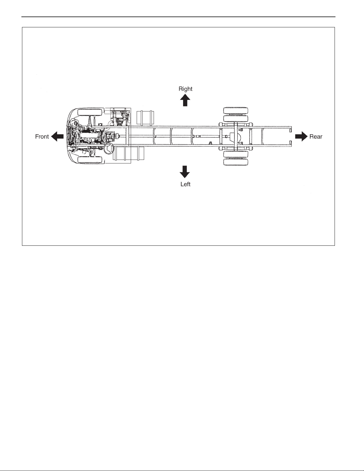
Definition of vehicle right and left.
Right and left refers to the left and right sides of the vehicle as seen
while looking down the center line from the rear towards the front.
Page 20
GENERAL INTRODUCTION (CHASSIS)GN02–14
SHTS00Z000200015C
Page 21

GENERAL INTRODUCTION (CHASSIS) GN02–15
! WARNING
Loosen
saph00z000200008
Incorrect
saph00z000200009
Incorrect
Incorrect
Incorrect
saph00z000200010
PRECAUTIONS
EN00Z0002C100001
PRECAUTIONS FOR ELECTRICAL SYSTEM
1. REMOVING THE BATTERY CABLE
• Be sure to wait for at least ten minutes after the starter key is
turned to "LOCK" position before you disconnect the battery terminals from the battery, as the vehicle data is recorded on ECU
and DCU starts working for the exhaust gas after treatment after
the starter key is turned to "LOCK" position. Otherwise, the vehicle data will not be recorded on ECU properly and DCU will not
complete working properly, which may result in the malfunction
of DPR system and DEF-SCR system.
• The MIL (malfunction indicator light) may come on when the
starter key is turned to "ON" position again, even if you wait for
at least ten minutes before disconnecting the battery terminals
from the battery after the starter key is turned to "LOCK" position. In this case, use HINO DX Ⅱ to clear the DTC (P204F and
P068A), to turn off the MIL and to conduct DPR regeneration
manually.
(1) Before electrical system work, remove the cable from the minus termi-
nal of the battery in order to avoid burning caused by short-circuiting.
(2) To remove the battery cable, fully release the nut to avoid damage to
the battery terminal. Never twist the terminal.
2. HANDLING OF ELECTRONIC PARTS
(1) Never give an impact to electronic parts of a computer or relay.
(2) Keep electronic parts away from high temperatures and humidity.
(3) Never splash water onto electronic parts in washing the vehicle.
(4) Do not remove the harness connector, electric component box, and
cover except for repair and inspection.
If removal is necessary, pay attention that water and foreign matters
do not attach or enter to the connector, terminals, electric component
box, and cover.
In restoration, make sure there is no attachment or entry of water and
foreign matters and mount them properly, because it causes degradation of waterproof function.
3. HANDLING OF WIRE HARNESS
(1) Perform marking on a clamp and a clip and secure then in original
position so that the wire harness will not interfere with the end and
acute angle section of the body and a bolt.
(2) To attach a part, take care not to bite the wire harness.
Page 22

GENERAL INTRODUCTION (CHASSIS)GN02–16
! WARNING
! WARNING
Incorrect
Incorrect
Correct
saph00z000200011
4. HANDLING OF CONNECTOR
(1) To remove a connector, hold the connector (indicated by an arrow in
the figure) to pull it out. Never pull the harness.
(2) To remove a connector with lock, release the lock then pull it out.
(3) To connect a connector with lock, insert it until it clicks.
(4) To insert a test lead into the connector, insert it from behind the con-
nector.
(5) In case it is difficult to insert a test lead from behind the connector,
prepare a harness for inspection and perform inspection.
5. INSTALLATION OF BATTERY DISCONNECT SWITCH
• Installation of the battery disconnect switch on the power supply
circuit for the dosing control unit of DEF-SCR (DCU) may dam-
age or result in the malfunction of DEF-SCR system.
• Be sure to read and follow the procedures and instructions on
the service bulletin before the installation of the battery discon-
nect switch.
6. HANDLING OF BATTERY DISCONNECT SWITCH
• Wait for at least one minute before using the battery disconnect
switch after the starter key is turned to "LOCK" position.
Otherwise, the vehicle data will not be recorded on ECU properly,
which may result in the malfunction of DPR system.
Page 23

GENERAL INTRODUCTION (CHASSIS) GN02–17
saph00z000200012
PRECAUTIONS FOR ELECTRIC WELDING
1. PRECAUTION FOR ELECTRIC WELDING
Electrical components such as the alternator and tachograph are
directly connected to the battery and one end is earthed to the
chassis frame. Under these conditions, welding current will flow
back along the earth circuit if electric welding is carried out and
damage may be caused to the alternator, tachograph, electrical
components, etc. Consequently, the following precautions are
always to be taken during welding.
(1) Disconnect the earth terminal of the battery at the frame fitment and
earth the welding equipment securely to the frame itself. (Do not fit the
welding equipment earth to such things as the tire rims, brake pipes
or fuel pipes and leaf spring, etc.)
a. Turn the starter switch off.
b. Disconnect the negative terminal of the battery.
c. Earth welding equipment securely, near to the area to be welded.
d. Put back battery negative ground as original condition.
e. Finally check the functioning of all instruments.
Alternator
etc.
ARC welding
machine
Computer
Battery
Disconnect the ground terminal for
battery at the connecting point on the
frame and disconnect the ground for
computer as well.
Chassis frame Chassis frame
Connect the ground of the ARC welding
machine near the place on the frame to be
welded but not connect it to plated parts such
as fuel pipes, brake pipes and leaf spring.
(2) In order to prevent damage to ancillary equipment components from
sparks during welding, take steps such as putting fire-resistant covers
over things like the engine, meters, steering wheel, hoses, tubes, leaf
spring and tires.
Page 24
GENERAL INTRODUCTION (CHASSIS)GN02–18
! WARNING
SHTS00Z000200021
SHTS00Z000200022
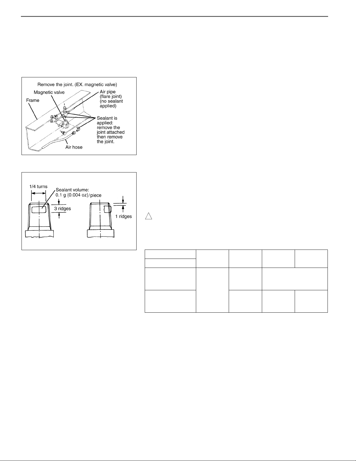
SEALANT ON THE TAPERED SCREW FOR PIPING
EN00Z00020200003
To the tapered thread of the air pipe joint is applied the sealant "LOC-TITE
#575". Follow the procedure below to remove/attach the piping.
1. REMOVAL
(1) The sealant (LOCTITE #575) has a high sealing capability. The return
torque of taper joint is about 1.5 times as high as the initial tightening
torque. To remove the joint, use a longer wrench.
(2) For replacement of joint in a place with poor workability, remove the
auxiliaries with the joint attached then remove the joint.
2. ATTACHING
(1) To apply sealant (LOCTITE #575), use waste and thinner to wipe the
dirt off the sealing section, directly apply the sealant by a quarter turn
(three ridges) starting from the second ridge from the tip, then assemble in accordance with the tightening torque table below.
Wipe dirt off the mating part (female screw) before tightening it.
In case the sealant has entered your eye or attached to your skin,
wash it away in running water.
Tightening torque of tapered joint Unit: Nm {kgfcm, lbfft}
Screw diameter
Material
1/8 1/4 3/8 1/2
4910
Steel
Aluminum, brass
205
{20050,
14.43.6}
{500100,
36.27.2}
255
{25050,
18.13.6}
6415 {650150, 4710}
345
{35050,
25.33.6}
445
{45050,
32.53.6}
(2) To replace vulcanized tape with sealant, remove the tape before-
hand, same as (1).
NOTICE
Take special care not to let dirt and foreign matters enter the piping.
(3) In the event of air leakage after sealant is applied and piping attached,
retightening cannot check the air leakage. Follow the steps (1) and (2)
to reassemble the piping.
Page 25

GENERAL INTRODUCTION (CHASSIS) GN02–19
One-touch joint
Caulking joint
SHTS00Z000200023
Insertion length
Nylon tube
SHTS00Z000200024
SHTS00Z000200025
Less than 5˚
SHTS00Z000200026
NYLON TUBE REPLACEMENT METHOD
EN00Z00020200004
NYLON TUBE REPLACEMENT METHOD
• In this vehicle, nylon tubes are used for all the air tubes except those
on the charge line and the rear axle, the tubing for the wheel power
signal, a portion of the accessory system tubing, and for the unloader
tubing, and it is also used in joints, depending on the connection conditions of the two types of joints; one-touch joints and caulking joints.
NOTICE
Since the function and quality of nylon tubes and joints are guaranteed as tube and joint sets, the use of parts other than Hino Genuine
Parts must be avoided.
1. ONE-TOUCH JOINT NYLON TUBE INSERTION LENGTH
DIAMETER
(Outside diameter x inside diam-
eter)
1/4 in. 14-19 {0.55-0.75}
3/8 in. 18-23 {0.71-0.91}
1/2 in. 21-26 {0.83-1.02}
INSERTION LENGTH
mm {in.}
2. REMOVAL OF A ONE-TOUCH JOINT
(1) Make sure there is no dirt or grease stuck to the connector end. If the
end is dirty, clean it thoroughly by air blowing or other means.
(2) Using the special tool for removing the nylon tube to push the connec-
tor end, pull off the nylon tube with your hand in one stroke, without
stopping partway, pulling the tube in the connector axial direction.
SST:
Puller (S0942-11490)
INSTALLATION OF A ONE-TOUCH JOINT AND CAULKING JOINT
• Make sure the joint interior is free of dirt grease. If the interior is dirty,
clean it thoroughly by air blowing or other means.
• Cut off the tube end where the tube surface is scarred by the joint
pinch marks, and make sure that the part of the tube inserted into the
joint has no surface damage. If the tube is damaged, cut off the damaged part (provided that the tube length is more than sufficient).
NOTICE
Use the special nylon tube cutter when cutting the nylon tube, and cut
the tube so that the angle of the cut end to the axial center is 85-95.
1. INSTALLATION OF A ONE-TOUCH JOINT
Page 26

GENERAL INTRODUCTION (CHASSIS)GN02–20
Aligning marks
SHTS00Z000200027
•
Before inserting the tube, mark the insertion length on the tube with a
white-out pen or similar implement, in accordance with the dimensions, "ONE-TOUCH JOINT NYLON TUBE INSERTION LENGTH."
Then insert the tube firmly in place as far as the marked point.
2. INSTALLATION OF A CAULKING JOINT
• Press in the tube so that it does not move (will not come out), and
tighten the sleeve nut with the tightening tool to the torque shown in
the following table.
3. NYLON TUBE NUT TIGHTENING TORQUE
Unit: Nm {kgfcm, lbfft}
NUT DIAMETERS TIGHTENING TORQUE
1/4 in. 20-26 {200-270, 15-19}
3.8 in. 35-45 {350-460, 26-33}
1/2 in. 50-60 {500-610, 37-44}
NOTICE
Nuts must be tightened to 5- 35C.
4. ASSEMBLING THE CAULKING JOINT (AFTER THE TUBE HAS
FIRST BEEN REMOVED FROM THE JOINT AND THEN REINSTALLED IN THE SAME PLACE)
(1) Make aligning marks on the connector and union to mark their posi-
tions before loosening the nut.
(2) When re-assembling the joint, tighten the nut until the pre-disassem-
bly position (position of aligning marks) is reached, and then tighten
the nut 60 more.
(3) Always check air leakage after assembling the joint. If air is leaking
from the joint, continue tightening the sleeve nut until the leak stops.
(4) If the air leak does not stop, replace the tube, sleeve, and insert with
new parts. If the air leak still continues, replace the nut and connector
/ union.
NOTICE
• During repair or other work, make sure the temperature limit of
the nylon tube is within -40-90C, especially during paint drying
work.
• During boring, welding, sanding, and other work, protect nylon
tubes from tools, cuts, heat sources, and sparks, or remove the
nylon tubes beforehand.
• Do not attach a welding equipment clamp near the nylon tube.
• Do not pour battery fluid or other acidic fluid on the nylon tube.
• Do not bend the nylon tube beyond the nylon tube bending
radius R values shown in the following table. Also, do not use
the remaining portion of a tube that has broken due to overbending.
OUTSIDE DIAMETER OF
TUBE
MINIMUM BENDING RADIUS DURING
HANDLING: R mm {in.}
1/2 in. 30 {1.18}
3/8 in. 65 {2.56}
1/2 in. 70 {2.76}
Page 27

GENERAL INTRODUCTION (CHASSIS) GN02–21
Metric system
M12-1.75 25
DT L
P
7
T
L
D
7
9
D- Nominal Diameter P- Property Class
(millimeters) (bolt strength)
L- Length (millimeters) T- Thread Pitch (thread
width crest to crest
millimeters)
Metric Bolts P Identification class numbers correspond to bolt strength. Increasing numbers represent increasing strength.
Nomenclature for bolts
Bolt strength identification
Bolt
SHTS00Z000200028
METRIC INFORMATION
EN00Z00021200001
METRIC FASTENERS
1. Most threaded fasteners on the Hino trucks series are metric.
Be careful not to mix them up with threaded fasteners using the
inch system.
Mismatched or incorrect bolts, nuts and screws can cause damage or malfunction, resulting in personal injury and/or property
damage.
2. When bolts, nuts and screws are removed from the vehicle, they
should be kept for reuse whenever possible.
If they are not re-usable, parts that are equivalent to the original
parts in dimensions, strength, and thread pitch must be
selected.
3. Most original bolts are marked with identification numbers indicating the strength of the bolts. The markings are shown below.
4. When replacing bolts, be careful to use bolts with the same
markings as the original bolts.
Page 28

GENERAL INTRODUCTION (CHASSIS)GN02–22
DECIMAL AND METRIC EQUIVALENTS
Fractions Decimal In. Metric mm. Fractions Decimal In. Metric mm.
1/64 0.015625 0.397 33/64 0.515625 13.097
1/32 0.03125 0.794 17/32 0.53125 13.494
3/64 0.046875 1.191 35/64 0.546875 13.891
1/16 0.0625 1.588 9/16 0.5625 14.288
5/64 0.078125 1.984 37/64 0.578125 14.684
3/32 0.09375 2.381 19/32 0.59375 15.081
7/64 0.109375 2.778 39/64 0.609375 15.478
1/8 0.125 3.175 5/8 0.625 15.875
9/64 0.140625 3.572 41/64 0.640625 16.272
5/32 0.15625 3.969 21/32 0.65625 16.669
11/64 0.171875 4.366 43/64 0.671875 17.066
3/16 0.1875 4.763 11/16 0.6875 17.463
13/64 0.203125 5.159 45/64 0.703125 17.859
7/32 0.21875 5.556 23/32 0.71875 18.256
15/64 0.234375 5.953 47/64 0.734375 18.653
1/4 0.250 6.35 3/4 0.750 19.05
17/64 0.265625 6.747 49/64 0.765625 19.447
9/32 0.28125 7.144 25/32 0.78125 19.844
19/64 0.296875 7.54 51/64 0.796875 20.241
5/16 0.3125 7.938 13/16 0.8125 20.638
21/64 0.328125 8.334 53/64 0.828125 21.034
11/32 0.34375 8.731 27/32 0.84375 21.431
23/64 0.359375 9.128 55/64 0.859375 21.828
3/8 0.375 9.525 7/8 0.875 22.225
25/64 0.390625 9.922 57/64 0.890625 22.622
13/32 0.40625 10.319 29/32 0.90625 23.019
27/64 0.421875 10.716 59/64 0.921875 23.416
7/16 0.4375 11.113 15/16 0.9375 23.813
29/64 0.453125 11.509 61/64 0.953125 24.209
15/32 0.46875 11.906 31/32 0.96875 24.606
31/64 0.484375 12.303 63/64 0.984375 25.003
1/2 0.500 12.7 1 1.00 25.4
Page 29

GENERAL INTRODUCTION (CHASSIS) GN02–23
No Mark
7
q
SPECIFIED TORQUE FOR STANDARD BOLTS AND NUTS
Class 4T 7T 9T
Representation
Diameter
M6
M8 11.5-16.5 {114-172, 8.3-12.4}
M10
M12
M14
M16
{976-1,464, 70.6-105.8}
4.4-6.6
{45-67, 3.3-4.8}
22.0-32.0
{221-331, 16.0-23.9}
38.5-57.5
{392-588, 28.4-42.5}
62.0-92.0
{629-943, 45.5-68.1}
96.0-144.0
{976-1,464, 70.6-105.8}
{1,552-2,328, 112.3-168.3}
7.2-10.8
{74-110, 5.4-7.9}
18.0-26.0
{179-269, 13.0-19.4}
34.5-51.5
{351-527, 25.4-38.1}
61.0-91.0
{621-931, 44.9-67.3}
96.0-144.0
152.0-228.0
{816-1,224, 59.0-88.5}
{1,304-1,956, 94.3-141.4}
{2,040-3,060, 147.5-221.2}
EN00Z00023200001
Unit: Nm {kgfcm, lbfft.}
9.5-13.5
{94-140, 6.8-10.1}
23.5-34.5
{237-355, 17.2-25.6}
46.0-68.0
{466-698, 33.7-50.4}
80.0-120.0
128.0-192.0
200.0-300.0
M18
M20
M22
M24
132.0-198.0
{1,344-2,016, 97.2-145.7}
188.0-282.0
{1,920-2,880, 138.8-208.2}
256.0-384.0
{2,616-3,924, 189.2-283.7}
324.0-486.0
{3,304-4,956, 238.9-358.3}
{2,120-3,180, 153.3-229.9}
{3,024-4,536, 218.7-327.9}
{4,120-6,180, 297.9-446.8}
{5,220-7,840, 377.5-566.8}
208.0-312.0
296.0-444.0
405.0-605.0
515.0-765.0
SPECIFIED TORQUE FOR FLANGE BOLTS AND NUTS
Diameter
M8
M10
M12
Class
{184-265, 13.3-19.2}
{421-631, 30.5-45.6}
{744-1,116, 53.8-80.7}
7T 9T 12T Shape
18.0-26.0
41.5-61.5
{560-840, 40.5-60.7}
73.0-109.0
{979-1,469, 70.8-106.2}
——
55.0-82.0
96.0-114.0
—
—
276.0-414.0
{2,816-4,224, 203.6-305.4}
392.0-588.0
{4,000-6,000, 289.3-433.8}
540.0-800.0
{5,470-8,210, 395.5-593.6}
680.0-1,010.0
{6,900-10,340, 499.0-747.6}
EN00Z0002C100002
Unit: Nm {kgfcm, lbfft.}
M14 — —
86.0-142.0
{877-1,448, 63.4-104.7}
Page 30

GENERAL INTRODUCTION (CHASSIS)GN02–24
With new flange (w/o grooves)
Unit: Nm {kgfcm, lbfft.}
Diameter
Class
M8
M10
M12
M14 —
{221-411, 16.0-29.7}
{250-464, 18.1-33.6}
{450-835, 32.5-60.4}
8.8T 10.9T Shape
21.7-40.3
24.5-45.5
44.1-81.9
27.3-50.7
{278-517, 20.1-37.4}
32.7-60.3
{333-615, 24.1-44.5}
57.4-106.6
{585-1087, 42.3-78.6}
91-169
{928-1723, 67.1-124.6}
104-156*
{106-1590, 76.7-115.1}
Page 31

GENERAL INTRODUCTION (CHASSIS) GN02–25
RECOMMENDED LUBRICANTS
EN00Z0002H600001
No. LUBRICANTS POSITONS VISCOSITY RECOMENDATIONS (SAE)
Engine oil
A.P.I.: CJ-4
1
JASO: DH-2
ACEA: E–6, E-9
No. LUBRICANTS POSITONS ATMOSPHERIC TEMP. S.A.E. No
Heavy duty engine oil
MIL-L-2104D, API-CD, or Cat
TO-4
2
Automotive gear oil API-MT-1
Mobil Delvac Synthetic
Transmission Fluid 50,
Shell SPIRAX GSX SAE 50,
EATON Roadranger SAE 50,
3
EATON Approved Synthetic
Transmission oil,
or equivalent (See Eaton
Lubrication Manual for detail)
Automatic transmission fluid;
TES 389-approved fluid
4
Automatic transmission fluid;
TES 295-approved fluid
Axle lubricant
Non- Extended Drain Lubricants
(Petroleum with EP Additives)
(A.P.I. GL-5) (MIL-PRF-2105E
and SAE J2360)
5
Axle lubricant
Extended Drain Lubricants
(Petroleum with EP Additives)
(A.P.I. GL-5) (MIL-PRF-2105E
and SAE J2360)
Cylinder Block
EATON Fuller
FS-5406A,FS-6406A
EATON Fuller
FS-5406A, FS-6406A
Allison 2200HS, 2200RDS,
2500RDS, 3000RDS,
3500RDS
Allison 2200HS, 2200RDS,
2500RDS, 3000RDS,
3500RDS
Rear axle
Above 10F (–12C) 50
Above 10F (–12C) 40
Below 10F (–12C) 30
Above 10F (–12C) 80W-90
Below 10F (–12C) 75W
All 50
——
Above 10F (–12C) 85W/140
Above –15F (–26C) 80W/140
Above –15F (–26C) 80W/90
Above –40F (–40C) 75W/90
From –40F (–40C) to –35F (2C) 75W
Above –40F (–40C) 75W/140
Above –15F (–26C) 80W/90
Above –15F (–26C) 80W/90
Above –40F (–40C) 75W/140
Above –40F (–40C) 75W/90
Page 32

GENERAL INTRODUCTION (CHASSIS)GN02–26
No. LUBRICANTS POSITONS
6 POWER STEERING FLUID (ATF DEXRON 2 or 3) Integral Power Steering Gear
7 BRAKE AND CLUTCH FLUID (DOT-3) or (DOT-4) Brake & Clutch
WHEEL BEARING GREASE
8
(MIL-G-10924B/18709A) (N.L.G.I.'s No.2 LITHIUMSOAP)
HEAT RESISTANCE GREASE
9
(MIL-G-22615/23549/21164) (N.L.G.I.'s No.2 or No.3)
10 SPECIAL GREASE (KLUBER GLKO) B-Frame Disc Brake (Guide buss, Caliper body, Piston)
11 STARTER GREASE (N.L.G.I.'s No.2 LITHIUM-SOAP)
12 BEARING GREASE (N.L.G.I.'s No.2 LITHIUM-SOAP)
CHASSIS GREASE (MIL-G-17740) (N.L.G.I.'s No.1
13
CALCIUM or LITHIUM-SOAP)
14 LONG LIFE COOLANT Engine, Radiator
15 Mobil Synthetic 75W-90 Front Wheel Hub (Oil Lubricated Bearings)
Propeller Shaft Universal Joint and Slip Joint
Clutch Disc Hub Spline
T/M Main Drive Shaft Spline
Q-Plus Brake (Retainer Clip, Anchor Pin, Roller (Journal only), Camshaft, Automatic Slack Adjuster, Clevis
Pin) Parking Brake (Camshaft, Anchor Pin, Shoe web)
Bushing, Clutch, Drive Shaft, Pinion Shaft Lever &
Reduction Gear
Clutch Release Sleeve
Clutch Release Shaft
Alternator Bearing
Starter Bearing
Chassis Grease Fitting
No. LUBRICANTS POSITONS SHEEL MOBIL EXXON
LITHIUM BASE DISULFIDE
16
MOLYBDENUM GREASE
Drag Link & Tie
Rod Ball Joint
Retinax AM
Mobil Grease
Special
Beacon Q2
Page 33

GENERAL INTRODUCTION (CHASSIS) GN02–27
VEHICLE LIFT AND SUPPORT LOCATIONS
EN00Z0002A200001
1. NOTICE ABOUT VEHICLE CONDITION WHEN JACKING UP
(1) As a rule, vehicle must be in an unloaded condition and never jack up
or lift up the vehicle with things of heavy weight.
(2) If removing any things of heavy weight like the engine and transmis-
sion, the center of gravity of the vehicle moves. Therefore, place a balance weight so as to keep it from rolling, or hold the jacking support
location using the transmission jack.
2. NOTICE FOR USING 4 POST LIFT
(1) Follow the instruction manual for a safety operation.
(2) Do not damage tires or wheels with a free wheel beam.
(3) Using a wheel stopper, fix the vehicle.
3. NOTICE FOR USING JACK AND SAFETY STAND
(1) Work in a flat place using a wheel stopper all the time.
(2) Support the specified location with a jack and safety stand accurately.
(3) Do not work or leave the vehicle supported only by a jack. Be sure to
support the vehicle together with a safety stand.
(4) Be careful and accurate in jacking up and down the vehicle.
(5) Care must be taken when jacking up and supporting the vehicle. Be
sure to lift and support the vehicle at the proper locations.
• Cancel the parking brake on a level place and shift the transmission in
Neutral.
• When jacking up the front wheels of the vehicle at first place stoppers
behind the rear wheels.
• When jacking up the rear wheels of the vehicle at first place stoppers
behind the front wheels.
• When either the front or rear wheels only should be jacked up, set
safety stands and place stoppers in front and behind the other wheels
on the ground.
• After the vehicle is jacked up, be sure to support it on the safety
stands. It is extremely dangerous to perform any work on a vehicle
raised on a jack alone, even for a small job that can be finished
quickly.
Page 34

GENERAL INTRODUCTION (CHASSIS)GN02–28
Front Rear
Leaf suspension
Air suspension
Air spring
Front
Rear
Center of front axle beam
Center of rear axle housing
Garage jack position
Safety stand
If necessary, remove the front bumper.
Support position
Oil jack position
SHTS00Z000200034
Page 35

GENERAL INTRODUCTION (CHASSIS) GN02–29
Information display control switch
Information display
SHTS00Z000200035C
MODE
SELECT
SET/RESET
SHTS00Z000200036
INFORMATION DISPLAY
EN00Z0002A200002
1. INFORMATION DISPLAY ITEMS
• Information display shows following items.
(1) Ordinary display
Trip meter, voltage, date, fuel consumption, average speed and
engine or vehicle maintenance information etc.
(2) Warning display
The warning display is automatically displayed and shows messages.
NOTICE
• When turn the key to "ON" position, display shows last message.
But in case of device operating, the warning display is prior to
ordinary display.
2. INFORMATION DISPLAY CONTROL SWITCH
• The following information is shown with the key turned on. Each time
you push the "MODE" button, the displayed information is changed.
NOTICE
• Diagram on the next page shows the operation method of the
information display.
• If you push and hold "SET/RESET" button, as the display case,
data may be reset.
• Press the "MODE" button more than 1 second to release the
warning information.
Page 36

GENERAL INTRODUCTION (CHASSIS)GN02–30
Push and hold
for at least 1sec.
Push down "MODE " button
The system remembers last display at each function.
Push button "SET/RESET" at the same time
Push up "SELECT " button
Other : Those displays are broken in automatically
Secondary
Setting
Maintenance
Self check
Self check
Normal display item
Operation menu Control menu
Secondary
Setting
Maintenance
Returns to last display automatically
Fuel consumption monitor
Trip data
Operation time
DPR
Water temperature
Voltage meter
Setting cannot be made while driving.
Push and hold
for at least 1sec.
(Starter key ON)
Interruption display
Water temp
Voltage
DPR
Current
Average
Main menu
Clock
Language
Units
Display
Conversion rate
Engine oil
T/M oil
Diff oil
Coolant
Fuel filter
Belt
DPR
Tu rb o
Starter
Alternator
Radiator
Battery
Air dryer
Customize 1
Customize 2
Customize 3
SHTS00Z000200037
Page 37

GENERAL INTRODUCTION (CHASSIS) GN02–31
3. WARNING DISPLAY
(1) Warning display
Display Warning Display remarks
Engine control system has malfunction. This is
important and must be addressed immediately.
DPR cleaner needs to be manually regenerated.
NOTICE
• The display shows DPR MANUAL REGENERATE REQUIRED with
the buzzer sound when DPR cleaner needs to be manually regen-
erated.
(2) Information display
Display Display remarks
Appears when idling is stopped due to emergency.
DPR regenerate on time.
DPR remaining for few minute.
DPR regenerate completed.
DPR regeneration interrupted, push DPR button to resume.
NOTICE
• The DPR system automatically regenerates when the quantity of
soot collected in the DPR cleaner exceeds a specific quantity.
This prevents an abnormal accumulation of soot and keeps the
DPR cleaner in good condition. Use of high-performance catalyst
and an electronically controlled common rail fuel injection sys-
tem has made it possible to burn (regenerate) the soot while
driving.
Page 38

GENERAL INTRODUCTION (CHASSIS)GN02–32
SHTS00Z000200044
599999
599000
Disable
SHTS00Z000200049
4. SELF DIAGNOSIS SYSTEM
If the vehicle has fault, display shows the trouble.
(1) Select to "Self check" and push "SET/RESET" button.
(2) Select to "System check" and push "SET/RESET" button, display
shows "No fault" in case of no trouble. If it has trouble, display shows
fault item.
(3) If display shows trouble warning, Immediately get the vehicle checked
and repaired at an authorized Hino dealer.
(4) In case of "Engine malfunction" displayed, push and hold "SELECT"
button for more than 1 sec. until the display shows trouble code.
Push "SELECT" button, display shows another trouble codes, if there
are.
(5) Push and hold "SELECT" button for longer than 1 sec. to display the
"Inactive".
(6) Trouble code display
Initial Display Remarks
It has no trouble.
It has trouble.
Yellow background.
It has trouble code, now.
Get the vehicle checked and repaired.
It had trouble code, previously.
5. RESETTING PROCEDURE
EX.Differential oil change period
(1) Scroll up and select "Maintenance" and push "SET/RESET" button.
(2) Scroll up and select the preferred setting item and push "SET/
RESET" button.
(3) Push and hold "SET/RESET" button for longer than 1 sec.
NOTICE
• In the case of the other item on trouble code, data may be reset
as the same procedure.
• But, especially in the case of "DPR", push and hold "MODE" and
"SET/RESET" button at the same time for more than 20sec. to
reset. (Following to the low, use only at an authorized Hino
dealer.)
Page 39

GENERAL INTRODUCTION (CHASSIS) GN02–33
6. AVAILABLE SETTING ITEMS
• Engine oil
• T/M oil
• Diff oil
• Coolant
• Fuel filter
• Belt
• DPR
• Tu rbo
• Starter
• Alternator
• Radiator
• Battery
• Air dryer
• Customize1
• Customize2
• Customize3
Page 40

GENERAL INTRODUCTION (CHASSIS)GN02–34
Vibrate slightly
Vibrate
slightly
Shake slightly
SHTS00Z000200050
SYMPTOM SIMULATION
EN00Z0002A200003
HINT
The most difficult case in troubleshooting is when no problem symptoms occur. In such a case, a thorough problem analysis must be carried out. A simulation of the same or similar conditions and
environment in which the problem occurred in the customer's vehicle
should be carried out. No matter how much skill or experience a technician has, troubleshooting without confirming the problem symptoms will lead to important repairs being overlooked and mistakes or
delays.
For example:
With a problem that only occurs when the engine is cold or as a result
of vibration caused by the road during driving, the problem can never
be determined if the symptoms are being checked on a stationary
vehicle or a vehicle with a warmed-up engine. Vibration, heat or water
penetration (moisture) is difficult to reproduce. The symptom simulation tests below are effective substitutes for the conditions and can
be applied on a stationary vehicle. Important points in the symptom
simulation test: In the symptom simulation test, the problem symptoms as well as the problem area or parts must be confirmed. First,
narrow down the possible problem circuits according to the symptoms. Then, connect the tester and carry out the symptom simulation
test, judging whether the circuit being tested is defective or normal.
Also, confirm the problem symptoms at the same time. Refer to the
problem symptoms table for each system to narrow down the possible causes.
1. VIBRATION METHOD: When malfunction seems to occur as a
result of vibration.
(1) PART AND SENSOR
Apply slight vibration with a finger to the part of the sensor suspected
to be the cause of the problem, and check whether or not the malfunc-
tion occurs.
NOTICE
Applying strong vibration to relays may open relays
(2) CONNECTORS
Slightly shake the connector vertically and horizontally.
(3) WIRE HARNESS
Slightly shake the wire harness vertically and horizontally.
HINT
The connector joint and fulcrum of the vibration are the major areas
that should be checked thoroughly.
2. HEAT METHOD: When a malfunction seems to occur when the
area in question is heated.
(1) Heat the component that is the possible cause of the malfunction with
a hair dryer or similar device. Check if the malfunction occurs.
NOTICE
• Do not heat to more than 60C (140F). Exceeding this tempera-
ture may damage components.
• Do not apply heat directly to the parts in the ECU.
Page 41

GENERAL INTRODUCTION (CHASSIS) GN02–35
SHTS00Z000200051
3. WATER SPRINKLING METHOD: When a malfunction seems to
occur on a rainy day or in high-humidity.
(1) Sprinkle water onto the vehicle and check if the malfunction occurs.
NOTICE
• Never sprinkle water directly into the engine compartment. Indi-
rectly change the temperature and humidity by spraying water
onto the front of the radiator.
• Never apply water directly onto the electronic components.
HINT
If the vehicle has or had a water leakage problem, the leakage may
have damaged the ECU or connections. Look for evidence of corrosion or short circuits. Proceed with caution during water tests.
4. HIGH ELECTRICAL LOAD METHOD: When a malfunction seems
to occur when electrical load is excessive.
(1) Turn on the heater blower, headlight, rear window defogger and all
other electrical loads. Check if the malfunction reoccurs.
Page 42

GENERAL INTRODUCTION (CHASSIS)GN02–36
GLOSSARY
DEFINITION OF ABBREVIATION IN THIS MANUAL
LIST OF ABBREVIATION
SAE
ABBREVIATIONS
A/C Air conditioner
ABS Anti-lock Brake System
ACC Accessory
AMT Automated Manual Type
ATC After Turbo catalyst
ATF Automatic Transmission Fluid
CA Crank Angle
CAN Controller Area Network
CD-ROM Compact Disc Read Only Memory
CPU Central Processing Unit
dB Decibel
DC Direct Current
D-CAT Diesel-Clean Advanced Technology System
DC motor Direct Current Motor
SAE TERMS
DCU Dosing Control Unit
DEF Diesel Exhaust Fluid
DPR Diesel Particulate active Reduction System
DSS Driving Support System
ECU Electronic Control Unit
EEPROM Electronically Erasable and Programmable Read Only Memory
EGR Exhaust Gas Recirculation
ELR Emergency Locking Retractor
ENG Engine
ES START Easy and Smooth start system
F/A Front axle
FCCB Fuel Control Cylinder Balance
FCV Fuel Cutoff Valve
FF Shift Feather touch & Finger shift
FL Fusible link
Fr Front
FRP Fiber Reinforces Plastic
Page 43

GENERAL INTRODUCTION (CHASSIS) GN02–37
SAE
ABBREVIATIONS
FUP Front Underrun Protector
GND Ground
GVW Gross Vehicle Weight
Hi High
HINO DX Ⅱ Hino Diagnostic eXplorer Ⅱ
HVAC Heating, Ventilating and Air-Conditioning unit
I.S.C. Idle Speed Control
IC Integrated Circuits
ID Identification
IPD Intelligent Power Device
IS Idle Stop
ISO International Organization for Standardization
JIS Japanese Industrial Standards
LED Light Emitting Diode
SAE TERMS
LEV Low Emission Vehicle
LH Left Hand
LLC Long Life Coolant
Lo Low
MAX Maximum
MIN Minimum
MS evaporator Multi-rank and Super slim structure evaporator
No Number
NOx Nitrogen Oxide
NMR No load Maximum Revolution
OHC Over Head Camshaft
PC Personal Computer
PCD Pitch Circle Diameter
PCS Pre-Crash Safety
PCV Pump Control Valve
PCV valve Positive Crankcase Ventilation valve
PM Particulate Matter
PPG Glass-fiber-reinforced Polypropylene
PPm Parts Per Million
PS pump Power Steering Pump
Page 44

GENERAL INTRODUCTION (CHASSIS)GN02–38
SAE
ABBREVIATIONS
PVD Physical Vapor Deposit
PWR Power
QE code Quick Response Code
R/A Rear axle
RH Right Hand
SCR Selective Catalytic Reduction
SW Switch
T/M Transmission
SAE TERMS
Page 45

GENERAL INTRODUCTION (CHASSIS) GN02–39
GLOSSARY OF SAE AND HINO TERMS
EN00Z00020200005
This glossary lists all SAE-J2403 terms and abbreviations used in this manual in compliance with SAE recommendation, as
well as their HINO equivalents.
SAE
ABBREVIATIONS
A/T AUTOMATIC TRANSMISSION Automatic transmission
AAT AMBIENT AIR TEMPERATURE Ambient Air Temperature
ACL AIR CLEANER Air cleaner
ACL Element ACL (Air Cleaner) Element Air Cleaner element
ACL Element AIR CLEANER Element Air Cleaner element
ACL Housing AIR CLEANER Housing Air cleaner body assembly
ACL Housing Cover AIR CLEANER Housing Cover Air Cleaner Housing Cover
AFTDEF
AFTDEFDU
AFTDOC
AFTERTREATMENT DIESEL EXHAUST
FLUID
AFTERTREATMENT DIESEL EXHAUST
FLUID DOSING UNIT
AFTERTREATMENT DIESEL OXIDATION
CATALYST
SAE TERMS
DEF
DCU
DOC (Diesel Oxidation Catalyst)
HINO TERMS
( )--ABBREVIATIONS
AFTDOS AFTERTREATMENT DOSER AFTDOS DEF injector
AFTDPF
AFTDPFDP
AFTEGT
AP ACCELERATOR PEDAL Accelerator pedal
AP Sensor ACCELERATOR PEDAL Sensor Accelerator Pedal Position Sensor
APP ACCELERATOR PEDAL POSITION Accelerator Pedal Position
CAC CHARGE AIR COOLER Intercooler
CPP Switch CLUTCH PEDAL POSITION Switch Clutch Switch
DCC DIAGNOSTIC CONNECTOR, Cab Diagnosis connector
DCU DIAGNOSTIC CONNECTOR, Underhood Diagnosis connector
DRIVER DRIVER driver
DTC DIAGNOSTIC TROUBLE CODE Diagnosis Trouble Code
DTM Switch DIAGNOSTIC TEST MODE Switch Diagnosis switch
AFTERTREATMENT DIESEL PARTICULATE
FILTER
Aftertreatment Diesel Particulate Filter Differential Pressure
AFTERTREATMENT EXHAUST GAS TEMPERATURE
DPR filter
DPR differential pressure
Exhaust gas temperature
EBP EXHAUST BACK PRESSURE Backpressure
EBP EXHAUST BACK PRESSURE Exhaust backpressure
EBP Sensor EXHAUST BACK PRESSURE Sensor Back Pressure Sensor
Page 46

GENERAL INTRODUCTION (CHASSIS)GN02–40
SAE
ABBREVIATIONS
EBPR Valve
EC ENGINE CONTROL Engine control
ECT ENGINE COOLANT TEMPERATURE Coolant Temperature
ECT ENGINE COOLANT TEMPERATURE Water Temperature
EFT ENGINE FUEL TEMPERATURE Fuel temperature
EFT Sensor ENGINE FUEL TEMPERATURE Sensor Fuel temperature sensor
EGR EXHAUST GAS RECIRCULATION EGR
EGR Valve EXHAUST GAS RECIRCULATION Valve EGR valve
EGRT
EGRT Sensor
EGT EXHAUST GAS TEMPERATURE Exhaust gas temperature
EI ELECTRONIC IGNITION Ignition coil
EXHAUST BACK PRESSURE REGULATOR
Val ve
EXHAUST GAS RECIRCULATION TEMPERAT UR E
EXHAUST GAS RECIRCULATION TEMPERATURE Sensor
SAE TERMS
Exhaust control valve
EGR temperature
EGR exit temperature sensor
HINO TERMS
( )--ABBREVIATIONS
EOP ENGINE OIL PRESSURE Oil Pressure
EOT ENGINE OIL TEMPERATURE Oil Temperature
FP FUEL PUMP Fuel pump
FUEL PRESSURE Sensor FUEL PRESSURE Sensor Fuel Pressure sensor
GLOW PLUG GLOW PLUG Glow plug
GND GROUND GROUND
IA INTAKE AIR Air Intake
IA System INTAKE AIR System Air Intake System
IAT INTAKE AIR TEMPERATURE Intake temperature
IAT Sensor INTAKE AIR TEMPERATURE Sensor Intake temperature sensor
IDLE IDLE idle
IMAT INTAKE MANIFOLD AIR TEMPERATURE Intake manifold Air temperature sensor
IMAT INTAKE MANIFOLD TEMPERATURE Intake manifold temperature sensor
INJ INJECTOR Injector
MAF Sensor MASS AIR FLOW Sensor Air flow sensor
MIL MALFUNCTION INDICATOR LIGHT MIL (Malfunction Indicator Light)
OSS Sensor OUTPUT SHAFT SPEED Sensor Output Speed Sensor
OSS Sensor OUTPUT SHAFT SPEED Sensor Speed Sensor
PC Solenoid Valve PRESSURE CONTROL Solenoid Valve Solenoid control valves
PCV POS CRANKCASE VENTILATION PCV (Positive Crankcase Vent)
PCV Valve POS CRANKCASE VENTILATION Valve PCV (Positive Crankcase Vent) Valve
Page 47

GENERAL INTRODUCTION (CHASSIS) GN02–41
SAE
ABBREVIATIONS
PCV Valve POS CRANKCASE VENTILATION Valve PCV Valve
PCV Valve POSITIVE CRANKCASE VENT Valve PCV Valve
PNP PARK/NEUTRAL POSITION Neutral position
PNP Switch PARK/NEUTRAL POSITION Switch Neutral switch
RFP RAIL FUEL PRESSURE Common rail Pressure
RFP Sensor RAIL FUEL PRESSURE Sensor Common rail pressure sensor
SPARK PLUG SPARK PLUG Spark plug
SRI SERVICE REMINDER INDICATOR Check engine
ST SCAN TOOL Diagnostic tool
TC TURBOCHARGER Turbocharger
TCC TORQUE CONVERTER CLUTCH Torque Converter
TP Sensor THROTTLE POSITION Sensor Throttle Sensor
TSS Sensor TURBINE SHAFT SPEED Sensor Turbine Speed Sensor
VAF Sensor VOLUME AIR FLOW Sensor Air flow sensor
SAE TERMS
HINO TERMS
( )--ABBREVIATIONS
VLS VEHICLE LIMITING SPEED Speed Limiter Upper Limit
VSS VEHICLE SPEED SENSOR Vehicle Speed sensor
Page 48

CLUTCH MAIN UNIT (EATON 1401) CL02–1
CL02
CLUTCH MAIN UNIT (EATON 1401)
CLUTCH ASSEMBLY
(EATON SAS1401).................................... CL02-2
DATA AND SPECIFICATIONS..........................CL02-2
DESCRIPTION .................................................CL02-2
TROUBLESHOOTING......................................CL02-3
SPECIAL TOOL................................................CL02-5
COMPONENT LOCATOR.................................CL02-6
OVERHAUL ......................................................CL02-7
CLUTCH ASSEMBLY
(EATON SOLO1401) ............................... CL02-14
DATA AND SPECIFICATIONS........................CL02-14
COMPONENT LOCATOR...............................CL02-14
OVERHAUL ....................................................CL02-15
INSPECTION AND REPAIR ...........................CL02-22
CL02-001
Page 49

CLUTCH MAIN UNIT (EATON 1401)CL02–2
1
2
SHTS02Z020200001
CLUTCH ASSEMBLY (EATON SAS1401)
DATA AND SPECIFICATIONS
EN02Z0202I200001
CLUTCH FACING Unit: mm {in.}
Material Sintered metal (Ceramic metal)
Type Dry single plate with damper spring
Inside diameter 222 {8.8}
Outside diameter 350 {13.8}
Thickness 11.5 {0.45}
DESCRIPTION
EN02Z0202C100001
1 Clutch disc 2 Clutch cover
Page 50

CLUTCH MAIN UNIT (EATON 1401) CL02–3
TROUBLESHOOTING
Symptom Possible cause Remedy/Prevention
Clutch dragging. Clutch disc distorted or warped. Replace clutch disc.
Transmission input shaft worn. Replace input shaft and check clutch
hub for excessive wear. If worn,
replace disc. Check flywheel housing
alignment.
Excessive clutch control parts wear. Replace control parts.
Clutch control parts not functioning
properly.
Improper clutch control adjustment. Adjust clutch control.
Clutch disc assembly too thick. Replace clutch disc.
Clutch slipping. Release lever and release bearing
clearance incorrectly adjusted.
Clutch disc facing gummed with oil or
grease.
Release bearing worn. Replace bearing.
Clutch pedal free-play incorrectly
adjusted.
Compression spring weak. Replace cover assembly.
Clutch facing worn. Replace disc assembly.
Failing to remove plate from the clutch
pressure plate assembly.
Driver riding clutch pedal. Do not ride the clutch pedal.
Vehicle vibrates when starting. Improper engine idling. Adjust idling.
Clutch control incorrectly adjusted. Adjust clutch control
Clutch disc facing gummed with oil or
grease.
Glazed flywheel friction surface. Deglaze flywheel surface with coarse
Clutch disc distorted or warped. Replace disc.
Improper clutch cover tightening. Tighten bolts.
Flywheel housing misalignment. Replace flywheel housing.
Abnormal noise in transmission. Malfunction of engine. Tune up engine.
Improper clutch disc used. Replace proper clutch disc.
Trouble in transmission. Check transmission.
The engine idle speed is low. Increase the idle speed.
Replace control parts.
Adjust clearance.
Replace disc assembly.
Adjust free-play.
Remove plate.
Replace disc assembly.
emery cloth, stroking parallel to
machining lines.
EN02Z0202F300001
Page 51

CLUTCH MAIN UNIT (EATON 1401)CL02–4
Symptom Possible cause Remedy/Prevention
Noisy clutch. Release bearing worn or dried. Replace release bearing.
Pilot bearing worn or dried. Replace pilot bearing.
Clutch disc distorted or warped. Replace clutch disc.
Flywheel housing misalignment. Replace flywheel housing.
Transmission input shaft or clutch disc
spline worn.
Insufficient lubrication of pedal and its
accessories.
Insufficient lubrication of release shaft
and release bearing hub.
Transmission input shaft retainer
rusted or soiled.
Clutch pedal free-play incorrectly
adjusted.
Clutch pedal cannot be depressed. Clutch control incorrectly adjusted. Adjust clutch control.
Insufficient lubricant release shaft and
release bearing hub.
Change in clutch pedal give. Air trapped in clutch fluid. Bleed air.
Clean and lubricate or replace.
Lubricate.
Lubricate.
Clean or replace if rusted.
Adjust free-Play.
Lubricate.
Page 52

CLUTCH MAIN UNIT (EATON 1401) CL02–5
SPECIAL TOOL
Prior to starting a clutch overhaul, it is necessary to have these special tools.
Illustration Part number Tool name Remarks
S0965-01970
S0942-01442 SLIDING HAMMER
CLUTCH PILOT BEARING
PULLER
EN02Z0202K100001
S0966-21410 CLUTCH ALIGNING ARBOR
S0940-91200 CRANKING TOOL
Page 53

CLUTCH MAIN UNIT (EATON 1401)CL02–6
SHTS02Z020200006
COMPONENT LOCATOR
EN02Z0202D100001
1 Clutch cover 3 Adjusting screw
2Clutch disc 4Bolt
Tightening torque Unit: Nm {kgfcm, lbfft}
A 50-64 {510-655, 37-47}
Page 54

CLUTCH MAIN UNIT (EATON 1401) CL02–7
1.Remove the
transmission
SHTS02Z020200007
SHTS02Z020200008
SHTS02Z020200009
A.
Check cross-shafts
and bushings
SHTS02Z020200010
OVERHAUL
EN02Z0202H200001
IMPORTANT POINT - DISMOUNTING
1. REMOVE THE TRANSMISSION, SUPPORTING ITS WEIGHT TO
PREVENT DAMAGE TO THE BEARING AND DISCS.
2. INSTALL TWO WOODEN SPACERS 1"-1-1/2" THICK BETWEEN
RELEASE BEARING AND COVER ASSEMBLY.
3. REMOVE THE CLUTCH FROM THE FLYWHEEL.
IMPORTANT POINT - INSPECTION AND REPLACEMENT
1. REPLACE THE PILOT BEARING.
(1) Remove the pilot bearing.
SST:
Pilot Bearing Puller (S0965-01970)
Sliding Hammer (S0942-01442)
(2) Using a suitable tapping rod, install the pilot bearing.
NOTICE
After installing the pilot bearing, ensure that it rotates smoothly.
2. CHECK THE FOLLOWING ITEMS FOR WEAR REPLACE ANY
WORN COMPONENTS:
(1) Cross-shafts and bushings
NOTICE
Excessive wear at these points can cause a side loading condition.
Also, inspect the remaining pivot points of the linkage for excessive
wear.
Page 55

CLUTCH MAIN UNIT (EATON 1401)CL02–8
B.
Check release yoke
fingers
SHTS02Z020200011
D.
Check splines on the
input shaft
SHTS02Z020200012
E.
Check smooth
area of input
shaft for wear /
roughness
SAPH02Z080200001
(2) Release yoke fingers
(3) Splines on the input shaft
NOTICE
Any wear on the splines will prevent the newly installed driven discs
from sliding freely, thus causing poor release (clutch drag). Select a
disc out of the new installation and slide it full length on the transmission splines. This will detect a twisted input shaft. Replace input shaft
if disc does not freely slide.
(4) Smooth area of input shaft
(5) Mating surfaces
NOTICE
Inspect the mating surfaces of both the transmission bell housing and
the flywheel housing. Any appreciable wear on either housing will
cause misalignment. Most wear will occur between the 3 and 8 o'clock
positions.
Replace housings if worn.
Page 56

CLUTCH MAIN UNIT (EATON 1401) CL02–9
! CAUTION
1.
Insert 2 guide studs
Guide studs
SHTS02Z020200014
2.
Insert the aligning
tool through release
bearing sleeve
Aligning tool
SHTS02Z020200015
8
1
5
3
7
2
6
4
4.
Place disc on aligning
tool properly
orientated
SHTS02Z020200016
IMPORTANT POINT - MOUNTING
1. INSERT TWO (2) 3/8" x 16 UNC x 3" (76 MM) LONG GUIDE STUDS
INTO THE TWO UPPER MOUNTING HOLES OF THE FLYWHEEL.
2. INSTALL THE DISC BY INSERTING THE ALIGNING TOOL
THROUGH THE DISC SPLINES AND THEN INTO THE PILOT
BEARING.
SST:
Clutch Aligning Arbor (S0966-21410)
NOTICE
Make sure the side marked "Pressure Plate Side" faces the pressure
plate.
3. WITH THE ALIGNING TOOL STILL IN PLACE, CAREFULLY SLIDE
THE CLUTCH ASSEMBLY OVER THE ALIGNING TOOL AND THE
TWO (2) GUIDE STUDS WITH THE KWIK-ADJUST ALIGNED WITH
THE ACCESS HOLE IN THE BELL HOUSING.
4. INSTALL LOCKWASHER AND SIX (6) 3/8" x 16 UNC GRADE 5 OR
BETTER MOUNTING BOLTS AND HAND TIGHTEN.
(1) Remove the two (2) guide studs and replace with the remaining
mounting bolts with lockwasher. Using a torque wrench, progressively
tighten the eight (8) mounting bolts using the following crisis-cross
pattern. Starting at lower left.
Remove the shipping blocks from between the release bearing and
the cover assembly.
Tightening Torque:
50-64 Nm{510-665 kgfcm, 37-47 lbfft}
Failure to tighten these bolts in this manner can:
• Prevent the clutch cover from "centering" into the pilot area of
the flywheel.
• Cause permanent damage to the clutch cover (i.e. become
cracked or broken).
• Cause the clutch assembly to be out-of balance with the fly-
wheel.
Page 57

CLUTCH MAIN UNIT (EATON 1401)CL02–10
5.
Remove aligning tool
SHTS02Z020200017
6.
Shift transmission into gear
Shift into gear
SHTS02Z020200018
7.
Align the transmission
to the engine
SHTS02Z020200019
5. REMOVE THE ALIGNING TOOL.
6. SHIFT THE TRANSMISSION INTO GEAR.
7. POSITION THE TRANSMISSION SO THAT IT IS BOTH SQUARE
TO AND ALIGNED WITH THE ENGINE.
Page 58

CLUTCH MAIN UNIT (EATON 1401) CL02–11
! CAUTION
8.
Mesh input shaft and
disc (s) by rotating
output shaft
SHTS02Z020200020
SHTS02Z020200021
Socket wrench
Kwik-adjuster
SHTS02Z020200022
8. WHILE MOVING THE TRANSMISSION FORWARD, ROTATE THE
OUTPUT SHAFT OF THE TRANSMISSION UNTIL THE SPLINES
OF BOTH THE INPUT SHAFT AND THE DISC(S) MESH WITH
EACH OTHER. WHILE PERFORMING THIS TASK, YOU MUST
ALSO ENSURE THAT THE YOKE FINGERS REMAIN IN THE UP
POSITION UNTIL THEY CAN BE ROTATED OVER THE RELEASE
BEARING HOUSING INTO THEIR FINAL POSITION.
• Do not use the cross-shaft release lever (or a pipe over it) to pull
the transmission into its final position.
• Do not excessively force the transmission into the clutch assem-
bly or engine housing. If it does not enter freely, investigate the
cause of the problem and make any necessary changes.
• If the input shaft will not slide into the discs, they may need to be
repositioned. Do not let the transmission drop or hang unsupported in the driven discs.
This can cause the discs to become distorted and the clutch will
not release.
9. INSTALL THE TRANSMISSION MOUNTING BOLTS AND TORQUE
TO THE PROPER SPECIFICATION.
Tightening Torque:
37.5-48.5 Nm{382-494 kgfcm, 28-35 lbfft}
IMPORTANT POINT - ADJUSTMENT
1. CHECK LOCATION OF THE KWIK-ADJUSTER
(1) Remove the cover of inspection hole at the bottom of the clutch hous-
ing.
(2) If the Kwik-Adjuster exists in approachable position, adjustment can
be performed.
If position of the Kwik-Adjuster cannot be identified, perform following
procedure.
Page 59

CLUTCH MAIN UNIT (EATON 1401)CL02–12
SST
Crank
pulley
Torque
wrench
SHTS02Z020200023
Kwik-adjuster
SHTS02Z020200024
1 STEP: Master cylinder
push rod play
2 STEP:
Release cylinder
push rod play
Clutch pedal play
SHTS02Z020200025
SAPH02Z080200006
2. ARRANGE THE KWIK-ADJUSTER
(1) Set SST the crank pulley.
SST:
Cranking Tool (S0940-91200)
(2) Turn the crank pulley till the Kwik-Adjuster matches the inspection
hole.
Adjausting bolt
(push toward
clutch)
Kwik-adjust
3. ADJUSTING PROCEDURES
(1) Adjust the release bearing position;
• When the clutch disc is worn (pedal play less than limit)
Pedal play limit: 35 mm {1.38 in.}
• When the clutch disc replaced.
(2) Adjust the free travel by release cylinder push rod only;
• When the clutch disc or control linkage is replaced.
NOTICE
The above adjusting should be made after adjusting the release bearing position.
(3) Manual Adjust: Kwik-Adjust
• Depress adjusting bolt and rotate.
Kwik-Adjust will re-engage at 1/3 of a turn.
NOTICE
• Open-end wrenches are not recommended.
• Internal adjustments are performed with pedal down (clutch
released).
Page 60

CLUTCH MAIN UNIT (EATON 1401) CL02–13
Pedal
UP
Pedal
DOWN
SHTS02Z020200027
Master cylinder
Push rod
0
SHTS02Z020200028
Lock nut
3.18
SHTS02Z020200029
4. ADJUST THE RELEASE BEARING POSITION
(1) Set 1.75" (44 mm) dimension: With pedal down, turn adjusting ring to
obtain approximately 1.75" (44 mm). Turning the adjusting ring clockwise moves the release bearing toward the transmission. Turning the
adjusting ring counterclockwise moves the release bearing toward the
engine.
(2) Check release travel dimensions with release yoke rotated toward
release bearing, eliminating excess play in system. Having set this,
depress pedal down fully releasing clutch and check release travel to
settings shown.
NOTICE
It may be necessary to reduce the 1.75" (44 mm) settings to be able to
achieve 0.500"-0.562" (13-14 mm) travel on some models of transmissions.
5. ADJUST THE FREE TRAVEL
(1) Remove the return spring.
(2) Loosen the lock nut and turn the push rod counterclockwise until the
release bearing contacts the release lever plate or release lever.
(3) Turn the push rod clockwise about 3 1/3 turns.
Standard: Clearance between release bearing and
release yoke: 3.18 mm {0.125 in.}
(4) Tighten the lock nut.
Page 61

CLUTCH MAIN UNIT (EATON 1401)CL02–14
SHTS02Z020200030
CLUTCH ASSEMBLY (EATON SOLO1401)
DATA AND SPECIFICATIONS
EN02Z0202I200002
CLUTCH FACING Unit: mm {in.}
Material Sintered metal (Ceramic metal)
Type Dry single plate with damper spring
Inside diameter 222 {8.8}
Outside diameter 350 {13.8}
Thickness 11.5 {0.45} Adjustment-Free
COMPONENT LOCATOR
EN02Z0202D100002
Shipping bolts (4)
to be removed
at installation
Wear indicator
Section B-B
1 Clutch cover 3 Bolt
2Clutch disc
Tightening torque Unit: Nm {kgfcm, lbfft}
A 50-64 {510-655, 37-47}
Page 62

CLUTCH MAIN UNIT (EATON 1401) CL02–15
1.
Remove the
transmission
SHTS02Z020200031
2.
Located 4 hex head
machine screws
(4) 3/8" x 16 x 1-1/4" UNC
SHTS02Z020200032
SHTS02Z020200033
OVERHAUL
EN02Z0202H200002
IMPORTANT POINT - DISMOUNTING
1. REMOVE THE TRANSMISSION, SUPPORTING ITS WEIGHT TO
PREVENT DAMAGE TO THE BEARING AND DISCS.
NOTICE
If a SOLO Clutch is to be removed and reinstalled on the flywheel, four
(4) shipping bolts must be installed prior to unbolting the clutch (3/8"
x 16 UNC x 1-1/4").
2. LOCATE FOUR (4) 3/8" x 16 UNC x 1 - 1/4", HEX HEAD MACHINE
SCREWS. INSTALL THEM IN THE 4 COVER HOLES, TURNING
THEM ONE COMPLETE TURN AFTER THEY CONTACT THE
COVER.
3. REMOVE THE CLUTCH FROM THE FLYWHEEL.
IMPORTANT POINT - INSPECTION AND REPLACEMENT
1. REPLACE THE PILOT BEARING.
(1) Remove the pilot bearing.
SST:
Pilot Bearing Puller (S0965-01970)
Sliding Hammer (S0942-01442)
Page 63

CLUTCH MAIN UNIT (EATON 1401)CL02–16
SHTS02Z020200034
A.
Check cross-shaftsand
and bushings
SAPH02Z080200002
B.
Check release
yoke fingers
SAPH02Z080200003
D.
Check sptrings on the
input shaft
SAPH02Z080200004
(2) Using a suitable tapping rod, install the pilot bearing.
NOTICE
After installing the pilot bearing, ensure that it rotates smoothly.
2. CHECK THE FOLLOWING ITEMS FOR WEAR REPLACE ANY
WORN COMPONENTS.
(1) Cross-shafts and bushings
NOTICE
Excessive wear at these points can cause a side loading condition.
Also, inspect the remaining pivot points of the linkage for excessive
wear.
(2) Release yoke fingers
(3) Splines on the input shaft
NOTICE
Any wear on the splines will prevent the newly installed driven discs
from sliding freely, thus causing poor release (clutch drag). Select a
disc out of the new installation and slide it full length on the transmission splines. This will detect a twisted input shaft. Replace input shaft
if disc does not freely slide.
Page 64

! CAUTION
E.
SAPH02Z080200005
1.
Insert 2 guide studs
Guide studs
SHTS02Z020200039
2.
Insert the aligning
tool through release
bearing sleeve
Aligning tool
SHTS02Z020200040
8
1
5
3
7
2
6
4
4.
Place disc on aligning
tool properly
orientated
SHTS02Z020200041
Check smooth
area of input
shaft for wear /
roughness
CLUTCH MAIN UNIT (EATON 1401) CL02–17
(4) Smooth area of input shaft
(5) Mating surfaces
NOTICE
Inspect the mating surfaces of both the transmission bell housing and
the flywheel housing. Any appreciable wear on either housing will
cause misalignment. Most wear will occur between the 3 and 8 o'clock
positions.
Replace housings if worn.
IMPORTANT POINT - MOUNTING
1. INSERT TWO (2) 3/8" x 16 UNC x 3" (76 MM) LONG GUIDE STUDS
INTO THE TWO UPPER MOUNTING HOLES OF THE FLYWHEEL.
2. INSTALL THE DISC BY INSERTING THE ALIGNING TOOL
THROUGH THE DISC SPLINES AND THEN INTO THE PILOT
BEARING.
SST:
Clutch Aligning Arbor (S0966-21410)
NOTICE
Make sure the side marked "Pressure Plate Side" faces the pressure
plate.
3. WITH THE ALIGNING TOOL STILL IN PLACE, CAREFULLY SLIDE
THE CLUTCH ASSEMBLY OVER THE ALIGNING TOOL AND THE
TWO (2) GUIDE STUDS.
4. INSTALL LOCKWASHER AND SIX (6) 3/8" x 16 UNC MOUNTING
BOLTS HAND TIGHTEN.
(1) Remove the two (2) guide studs and replace with the remaining
mounting bolts with lockwasher. Using a torque wrench, progressively
tighten the eight (8) mounting bolts using the following crisis-cross
pattern. Starting at lower left.
Tightening Torque:
50-64 Nm{510-665 kgfcm, 37-47 lbfft}
Failure to tighten these bolts in this manner can:
• Prevent the clutch cover from "centering" into the pilot area of
the flywheel.
• Cause permanent damage to the clutch cover (i.e. become
cracked or broken).
• Cause the clutch assembly to be out-of balance with the fly-
wheel.
Page 65

CLUTCH MAIN UNIT (EATON 1401)CL02–18
5.
Remove aligning tool
SHTS02Z020200042
6.
Shift transmission into gear
Shift into gear
SHTS02Z020200043
7.
Align the transmission
to the engine
SHTS02Z020200044
(2) Remove the four (4) gold colored shipping bolts in a criss-cross pat-
tern.
NOTICE
Save these four (4) bolts for future use in case you need to remove,
then reinstall the SOLO Clutch.
5. REMOVE THE ALIGNING TOOL.
6. SHIFT THE TRANSMISSION INTO GEAR.
7. POSITION THE TRANSMISSION SO THAT IT IS BOTH SQUARE
TO AND ALIGNED WITH THE ENGINE.
Page 66

CLUTCH MAIN UNIT (EATON 1401) CL02–19
! CAUTION
8.
Mesh input shaft and
disc (s) by rotating
output shaft
SHTS02Z020200045
8. WHILE MOVING THE TRANSMISSION FORWARD, ROTATE THE
OUTPUT SHAFT OF THE TRANSMISSION UNTIL THE SPLINES
OF BOTH THE INPUT SHAFT AND THE DISC(S) MESH WITH
EACH OTHER. WHILE PERFORMING THIS TASK, YOU MUST
ALSO ENSURE THAT THE YOKE FINGERS REMAIN IN THE UP
POSITION UNTIL THEY CAN BE ROTATED OVER THE RELEASE
BEARING HOUSING INTO THEIR FINAL POSITION.
• Do not use the cross-shaft release lever (or a pipe over it) to pull
the transmission into its final position. Doing so may release the
clutch and "overstroke" the release bearing. The SOLO will
incorrectly "set" the release bearing position too close to the
transmission and cause the wear indication tab to move to 1/3-1/
2 the distance towards the "REPLACE" position.
• Do not excessively force the transmission into the clutch assem-
bly or engine housing. If it does not enter freely, investigate the
cause of the problem and make any necessary changes.
• If the input shaft will not slide into the discs, they may need to be
repositioned. If the clutch is to be unbolted from the flywheel, reinstall the shipping bolts and tighten one turn past contact with
the clutch. Now the installation shaft can be installed to reposition the discs and the clutch bolts re-torqued. Remove the shipping bolts to clamp the discs.
• Do not let the transmission drop or hang unsupported in the
driven discs.
This can cause the discs to become distorted and the clutch will
not release.
9. INSTALL THE TRANSMISSION MOUNTING BOLTS AND TORQUE
TO THE PROPER SPECIFICATION.
Tightening Torque:
37.5-48.5 Nm{382-494 kgfcm, 28-35 lbfft}
Page 67

CLUTCH MAIN UNIT (EATON 1401)CL02–20
Master cylinder
Push rod
0
SHTS02Z020200046
Stroke
pedal
5 times
SHTS02Z020200047
Master cylinder
Push rod
0
SHTS02Z020200046
Lock nut
3.18
SHTS02Z020200048
IMPORTANT POINT-SET-UP
1. ADJUST LINKAGE
(1) Remove the return spring.
(2) Loosen the lock nut and turn the push rod counterclockwise until the
release bearing contacts the release lever plate or release lever.
(3) Fully press the pedal up to 5 times to move the release bearing
slightly closer to the transmission and gain free-play in the cab.
2. ADJUST THE FREE TRAVEL
(1) Turn the push rod counterclockwise until the release bearing contacts
the release lever plate or release lever.
(2) Turn the push rod clockwise about 3 1/3 turns.
Standard: Clearance between release bearing and
release yoke: 3.18 mm {0.125 in.}
(3) Tighten the lock nut.
Page 68

CLUTCH MAIN UNIT (EATON 1401) CL02–21
SAPH02Z080200007
IMPORTANT POINT-CHECK WEAR INDICATOR
1. REMOVE THE COVER OF INSPECTION HOLE AT THE BOTTOM
OF THE CLUTCH HOUSING.
2. CHECK WEAR INDICATOR
• Reflects clutch wear and indicates when it is time to replace clutch.
• When replacing clutch, should change clutch disc together with clutch
cover.
New
Replace
Page 69

CLUTCH MAIN UNIT (EATON 1401)CL02–22
INSPECTION AND REPAIR
EATON SAS1401 and SOLO1401 Unit: mm {in.}
Inspection item Standard Limit Remedy Inspection procedure
Clutch facing thickness 11.43
{0.45}
Clutch disc misalignment 0-0.38
{0-0.0149}
Oily facings, Loose rivets,
— — Replace disc
Broken or loose damper
springs
Clearance between clutch
disc hub and transmission
0.05-0.15
{0.0020-0.0059}
input shaft spline
8.26
{0.33}
0.38
{0.0149}
0.5
{0.020}
Replace disc
Measure
assembly.
Replace. Measure
Visual check
assembly, if necessary.
Replace the
clutch disc or the
transmission
Measure
Clutch disk
input shaft.
EN02Z0202H300001
Clearance
Pressure plate misalignment
Pressure plate friction sur-
0-0.102
{0-0.040}
— — Replace the
face scoring or heat cracking
Flywheel misalignment 0.05
{0.0020}
or less
0.76
{0.029}
Replace the
clutch cover
Measure
assembly
Visual check
clutch cover
assembly.
NOTICE
Regrinding of the
pressure plate is
not possible.
1.0 {0.039} Replace. Measure
Input
Shaft
Page 70

CLUTCH MAIN UNIT (EATON 1401) CL02–23
Inspection item Standard Limit Remedy Inspection procedure
Flywheel friction surface
scoring or heat cracking
Flywheel misalignment — 0.15
Pilot bearing improper
rotation
— Grind limit
1.0 {0.039}
Deflection
limit
0.04
{0.00157}
{0.0059}
— — Replace, if neces-
Regrind the friction surface or
replace, if necessary.
NOTICE
Do not grind the
flywheel over the
limit.
Regrind the friction surface or
replace.
sary.
Visual check
Measure
Visual check
Page 71

CLUTCH MAIN UNIT (EATON 1401)CL02–24
! CAUTION
LUBRICATION (EATON SAS1401 and SOLO1401)
1. RELEASE BEARING
(1) The cast iron bearing housing will be equipped with either a standard
grease fitting or a lube tube extension. If a lube tube is not present, it
is necessary to remove the inspection cover to gain access to the
grease fitting. Apply grease until it purges from the rear of the housing.
2. RELEASE BEARING WEAR PADS
(1) Where the release fork contacts the bearing housing; there are small
hardened steel pads. Apply a small amount of grease to the wear
pads where the clutch release fork contacts.
3. CROSS-SHAFT BUSHINGS
(1) Lubricate both the left and the right cross-shaft bushings.
4. PILOT BEARING
(1) The pilot bearing inside the flywheel is a sealed for life bearing and
requires no lubrication.
RECOMMENDED LUBRICATION
Use a lithium soap base E.P. (Extreme Pressure) grease with a minimum of
+325 degree F operating range. It must meet the N.L.G.I.'s Grade 2 or 3
specs.
Incorrect grease and improper lube procedures will cause bearing
failures, bushing wearout, yoke tip and bearing wear pad wear.
Recommended Lubrication
Supplier Product Supplier Product
American Oil Co. Amoco Uthium-M.P. Grease Texaco Multifak #2
City Service Co. Citgo Premium Lithium Grease #2 Shell Oil Co. Retinax A
Fiske Refining Co. Lubriplate 630-2 Shell Oil Co. Aivania #2
Keystone Lubricating Co. #81 Ught *Chevron Oil Co. S.R.I. 1~
Mobil Mobilgrease M.P. *Texaco Premium RB
Humble Oil Co. Udok 2 *Exxon Unirex N3
Atlantic Richfield Co. Arco M.P.
* Approved for vendor prepack, other greases listed are for service only.
Page 72

CLUTCH MAIN UNIT (EATON 1402) CL02–1
CL02
CLUTCH MAIN UNIT (EATON 1402)
CLUTCH ASSEMBLY
(EATON SAS1402).................................... CL02-2
DATA AND SPECIFICATIONS..........................CL02-2
DESCRIPTION .................................................CL02-2
TROUBLESHOOTING......................................CL02-3
SPECIAL TOOL................................................CL02-5
COMPONENT LOCATOR.................................CL02-6
OVERHAUL ......................................................CL02-7
CLUTCH ASSEMBLY
(EATON SOLO1402) ............................... CL02-16
DATA AND SPECIFICATIONS........................CL02-16
COMPONENT LOCATOR...............................CL02-16
OVERHAUL ....................................................CL02-17
INSPECTION AND REPAIR ...........................CL02-27
CL02-002
Page 73

CLUTCH MAIN UNIT (EATON 1402)CL02–2
1 1
3
2
SHTS02Z020200001
CLUTCH ASSEMBLY (EATON SAS1402)
DATA AND SPECIFICATIONS
EN02Z0202I200001
CLUTCH FACING Unit: mm {in.}
Material Sintered metal (Ceramic metal)
Type Dry two plate with damper spring
Inside diameter 222 {8.8}
Outside diameter 350 {13.8}
Thickness 11.5 {0.45}
DESCRIPTION
EN02Z0202C100001
1 Clutch disc 3 Clutch cover
2 Intermediate plate
Page 74

CLUTCH MAIN UNIT (EATON 1402) CL02–3
TROUBLESHOOTING
Symptom Possible cause Remedy/Prevention
Clutch dragging. Clutch disc distorted or warped. Replace clutch disc.
Transmission input shaft worn. Replace input shaft and check clutch
hub for excessive wear. If worn,
replace disc. Check flywheel housing
alignment.
Excessive clutch control parts wear. Replace control parts.
Clutch control parts not functioning
properly.
Improper clutch control adjustment. Adjust clutch control.
Clutch disc assembly too thick. Replace clutch disc.
Clutch slipping. Release lever and release bearing
clearance incorrectly adjusted.
Clutch disc facing gummed with oil or
grease.
Release bearing worn. Replace bearing.
Clutch pedal free-play incorrectly
adjusted.
Compression spring weak. Replace cover assembly.
Clutch facing worn. Replace disc assembly.
Failing to remove plate from the clutch
pressure plate assembly.
Driver riding clutch pedal. Do not ride the clutch pedal.
Vehicle vibrates when starting. Improper engine idling. Adjust idling.
Clutch control incorrectly adjusted. Adjust clutch control.
Clutch disc facing gummed with oil or
grease.
Glazed flywheel friction surface. Deglaze flywheel surface with coarse
Clutch disc distorted or warped. Replace disc.
Improper clutch cover tightening. Tighten bolts.
Flywheel housing misalignment. Replace flywheel housing.
Abnormal noise in transmission. Malfunction of engine. Tune up engine.
Improper clutch disc used. Replace proper clutch disc.
Trouble in transmission. Check transmission.
The engine idle speed is low. Increase the idle speed.
Replace control parts.
Adjust clearance.
Replace disc assembly.
Adjust free-play.
Remove plate.
Replace disc assembly.
emery cloth, stroking parallel to
machining lines.
EN02Z0202F300001
Page 75

CLUTCH MAIN UNIT (EATON 1402)CL02–4
Symptom Possible cause Remedy/Prevention
Noisy clutch. Release bearing worn or dried. Replace release bearing.
Pilot bearing worn or dried. Replace pilot bearing.
Clutch disc distorted or warped. Replace clutch disc.
Flywheel housing misalignment. Replace flywheel housing.
Transmission input shaft or clutch disc
spline worn.
Insufficient lubrication of pedal and its
accessories.
Insufficient lubrication of release shaft
and release bearing hub.
Transmission input shaft retainer
rusted or soiled.
Clutch pedal free-play incorrectly
adjusted.
Clutch pedal cannot be depressed. Clutch control incorrectly adjusted. Adjust clutch control.
Insufficient lubricant release shaft and
release bearing hub.
Change in clutch pedal give. Air trapped in clutch fluid. Bleed air.
Clean and lubricate or replace.
Lubricate.
Lubricate.
Clean or replace if rusted.
Adjust free-Play.
Lubricate.
Page 76

CLUTCH MAIN UNIT (EATON 1402) CL02–5
SPECIAL TOOL
Prior to starting a clutch overhaul, it is necessary to have these special tools.
Illustration Part number Tool name Remarks
S0965-01970
S0942-01442 SLIDING HAMMER
CLUTCH PILOT BEARING
PULLER
EN02Z0202K100001
S0966-21420 CLUTCH ALIGNING ARBOR
S0940-91200 CRANKING TOOL
Page 77

CLUTCH MAIN UNIT (EATON 1402)CL02–6
5-A
1
4
2
3
SHTS02Z020200006
COMPONENT LOCATOR
EN02Z0202D100001
1 Clutch cover 4 Adjusting screw
2Clutch disc 5Bolt
3 Intermediate plate
Tightening torque Unit: Nm {kgfcm, lbfft}
A 50-64 {510-655, 37-47}
Page 78

CLUTCH MAIN UNIT (EATON 1402) CL02–7
1.
Remove the
transmission
SHTS02Z020200007
SHTS02Z020200008
SHTS02Z020200009
A.
Check cross-shafts
and bushings
SAPH02Z080200001
OVERHAUL
EN02Z0202H200001
IMPORTANT POINT - DISMOUNTING
1. REMOVE THE TRANSMISSION, SUPPORTING ITS WEIGHT TO
PREVENT DAMAGE TO THE BEARING AND DISCS.
2. INSTALL TWO WOODEN SPACERS 1"-1-1/2" THICK BETWEEN
RELEASE BEARING AND COVER ASSEMBLY.
3. REMOVE THE CLUTCH FROM THE FLYWHEEL.
IMPORTANT POINT - INSPECTION AND REPLACEMENT
1. REPLACE THE PILOT BEARING.
(1) Remove the pilot bearing.
SST:
Pilot Bearing Puller (S0965-01970)
Sliding Hammer (S0942-01442)
(2) Using a suitable tapping rod, install the pilot bearing.
NOTICE
After installing the pilot bearing, ensure that it rotates smoothly.
2. CHECK THE FOLLOWING ITEMS FOR WEAR REPLACE ANY
WORN COMPONENTS:
(1) Cross-shafts and bushings
NOTICE
Excessive wear at these points can cause a side loading condition.
Also, inspect the remaining pivot points of the linkage for excessive
wear.
Page 79

CLUTCH MAIN UNIT (EATON 1402)CL02–8
B.
Check release yoke
fingers
SAPH02Z080200002
D.
Check splines on the
input shaft
SAPH02Z080200003
SAPH02Z080200004
(2) Release yoke fingers
(3) Splines on the input shaft
NOTICE
Any wear on the splines will prevent the newly installed driven discs
from sliding freely, thus causing poor release (clutch drag). Select a
disc out of the new installation and slide it full length on the transmission splines. This will detect a twisted input shaft. Replace input shaft
if disc does not freely slide.
E.
Check smooth
area of input
shaft for wear /
roughness
(4) Smooth area of input shaft
(5) Mating surfaces
NOTICE
Inspect the mating surfaces of both the transmission bell housing and
the flywheel housing. Any appreciable wear on either housing will
cause misalignment. Most wear will occur between the 3 and 8 o'clock
positions.
Replace housings if worn.
Page 80

CLUTCH MAIN UNIT (EATON 1402) CL02–9
1.
Insert 2 guide studs
Guide studs
SHTS02Z020200014
2.
Insert the aligning
tool through release
bearing sleeve
Aligning tool
SHTS02Z020200015
3.
Place intermediate
plate properly
orientated
SHTS02Z020200016
IMPORTANT POINT - MOUNTING
1. INSERT TWO (2) 3/8" x 16 UNC x 3" (76 MM) LONG GUIDE STUDS
INTO THE TWO UPPER MOUNTING HOLES OF THE FLYWHEEL.
2. INSTALL THE FRONT DISC BY INSERTING THE ALIGNING TOOL
THROUGH THE DISC SPLINES AND THEN INTO THE PILOT
BEARING.
SST:
Clutch Aligning Arbor (S0966-21420)
NOTICE
Make sure the side marked "Flywheel" faces the flywheel.
3. INSTALL THE INTERMEDIATE PLATE ASSEMBLY OVER THE
TWO (2) GUIDE STUDS AND SLIDE IT FORWARD UNTIL IT
TOUCHES THE FLYWHEEL.
NOTICE
Make sure the side marked "Pressure Plate Side" is facing the pressure plate (the drive straps must face the pressure plate).
Page 81

CLUTCH MAIN UNIT (EATON 1402)CL02–10
4.
Remove aligning tool
Buttons
SHTS02Z020200017
5.
Slide cover assembly
over aligning tool
and guide studs
SHTS02Z020200018
4. REMOVE THE ALIGNING TOOL AND INSTALL IT THROUGH THE
SPLINES OF THE REAR DISC, AND INSERT THE ALIGNING
TOOL THROUGH THE FRONT DISC AND ALSO THE PILOT
BEARING.
NOTICE
Make sure the side of the disc marked "Pressure Plate Side" is facing
the pressure plate. As you complete this step, ensure that the ceramic
buttons align with each other as closely as possible. Doing so will aid
the function of the positive separator pins (roll pins).
5. WITH THE ALIGNING TOOL STILL IN PLACE, SLIDE THE COVER
ASSEMBLY OVER BOTH THE ALIGNING TOOL AND THE TWO (2)
GUIDE STUDS UNTIL IT RESTS AGAINST THE INTERMEDIATE
PLATE ASSEMBLY.
Page 82

CLUTCH MAIN UNIT (EATON 1402) CL02–11
! CAUTION
! CAUTION
8
1
5
3
7
2
6
4
6.
Place disc on aligning
tool properly orientated
SHTS02Z020200019
7.
Remove aligning tool
SHTS02Z020200020
SHTS02Z020200021
6. INSTALL LOCKWASHER AND SIX (6) 3/8" x 16 UNC MOUNTING
BOLTS HAND TIGHTEN.
(1) Remove the two (2) guide studs and replace with the remaining
mounting bolts with lockwasher. Using a torque wrench, progressively
tighten the eight (8) mounting bolts using the following criss-cross pattern. Starting at lower left.
Tightening Torque:
50-64 Nm{510-665 kgfcm, 37-47 lbfft}
Failure to tighten these bolts in this manner can:
• Prevent the clutch cover from "centering" into the pilot area of
the flywheel.
• Cause permanent damage to the clutch cover (i.e. become
cracked or broken).
• Cause the clutch assembly to be out-of balance with the fly-
wheel.
7. REMOVE THE ALIGNING TOOL.
8. USING A 1/4" (6 mm) DIAMETER FLAT NOSE PUNCH, LIGHTLY
TAP EACH OF THE FOUR (4) POSITIVE SEPARATOR PINS
TOWARD THE FLYWHEEL. PERFORMING THIS STEP WILL VERIFY THAT ALL FOUR (4) PINS ARE FLUSH AGAINST THE FLYWHEEL.
Failure to perform this step properly may cause the clutch to drag
(clutch does not release). Excessive force can damage the pins and
cause a release problem
NOTICE
The four (4) pins can also be set through the inspection opening of
the transmission bell housing if they were not to set prior to transmission installation.
Page 83

CLUTCH MAIN UNIT (EATON 1402)CL02–12
Top view
Roll pin
Clutch cover
Access hole
SHTS02Z020200022
Side view
Gap
0.20"-0.30"
(0.5-0.8mm)
Flywheel
Clutch cover
Roll pin (Qty.4)
Access hole
SHTS02Z020200023
9.
Shift transmission into gear
Shift into gear
SHTS02Z020200024
10.
Align the transmission
to the engine
SHTS02Z020200025
9. SHIFT THE TRANSMISSION INTO GEAR.
10. POSITION THE TRANSMISSION SO THAT IT IS BOTH SQUARE
TO AND ALIGNED WITH THE ENGINE.
Page 84

CLUTCH MAIN UNIT (EATON 1402) CL02–13
! CAUTION
11.
Mesh input shaft and
disc (s) by rotating
output shaft
SHTS02Z020200026
SHTS02Z020200027
Socket wrench
Kwik-adjuster
SHTS02Z020200028
11. WHILE MOVING THE TRANSMISSION FORWARD, ROTATE THE
OUTPUT SHAFT OF THE TRANSMISSION UNTIL THE SPLINES
OF BOTH THE INPUT SHAFT AND THE DISC(S) MESH WITH
EACH OTHER. WHILE PERFORMING THIS TASK, YOU MUST
ALSO ENSURE THAT THE YOKE FINGERS REMAIN IN THE UP
POSITION UNTIL THEY CAN BE ROTATED OVER THE RELEASE
BEARING HOUSING INTO THEIR FINAL POSITION.
• Do not use the cross-shaft release lever (or a pipe over it) to pull
the transmission into its final position.
• Do not excessively force the transmission into the clutch assem-
bly or engine housing. If it does not enter freely, investigate the
cause of the problem and make any necessary changes.
• If the input shaft will not slide into the discs, they may need to be
repositioned. Do not let the transmission drop or hang unsupported in the driven discs.
This can cause the discs to become distorted and the clutch will
not release.
12. INSTALL THE TRANSMISSION MOUNTING BOLTS AND TORQUE
TO THE PROPER SPECIFICATION.
Tightening Torque:
37.5-48.5 Nm{382-494 kgfcm, 28-35 lbfft}
IMPORTANT POINT - ADJUSTMENT
1. CHECK LOCATION OF THE KWIK-ADJUSTER
(1) Remove the cover of inspection hole at the bottom of the clutch hous-
ing.
(2) If the Kwik-Adjuster exists in approachable position, adjustment can
be performed.
If position of the Kwik-Adjuster cannot be identified, perform following
procedure.
Page 85

CLUTCH MAIN UNIT (EATON 1402)CL02–14
SST
Crank pulley
Torque
wrench
SHTS02Z020200029
Kwik-adjuster
SHTS02Z020200030
1 STEP: Master cylinder
push rod play
2 STEP:
Release cylinder
push rod play
Clutch pedal play
SHTS02Z020200031
Adjusting
bolt (push
toward
clutch)
Kwikadjust
SAPH02Z080200005
2. ARRANGE THE KWIK-ADJUSTER
(1) Set SST the crank pulley.
SST:
Cranking Tool (S0940-91200)
(2) Turn the crank pulley till the Kwik-Adjuster matches the inspection
hole.
3. ADJUSTING PROCEDURES
(1) Adjust the release bearing position;
• When the clutch disc is worn (pedal play less than limit)
Pedal play limit; 35 mm {1.38 in.}
• When the clutch disc replaced.
(2) Adjust the free travel by release cylinder push rod only;
• When the clutch disc or control linkage is replaced.
NOTICE
The above adjusting should be made after adjusting the release bearing position.
(3) Manual Adjust: Kwik-Adjust
• Depress adjusting bolt and rotate.
Kwik-Adjust will re-engage at 1/3 of a turn.
NOTICE
• Open-end wrenches are not recommended.
• Internal adjustments are performed with pedal down (clutch
released).
Page 86

CLUTCH MAIN UNIT (EATON 1402) CL02–15
0.75" (19mm)
Clutch
Transmission
MIN. 1.25
(32mm)
MAX. 1.32
(33mm)
Pedal
UP
Pedal
DOWN
SHTS02Z020200033
Master cylinder
Push rod
0
SHTS02Z020200034
Lock nut
3.18
SHTS02Z020200035
4. ADJUST THE RELEASE BEARING POSITION
(1) Set 0.75" (19 mm) dimension: With pedal down, turn adjusting ring to
obtain approximately 0.75" (19 mm). Turning the adjusting ring clockwise moves the release bearing toward the transmission. Turning the
adjusting ring counterclockwise moves the release bearing toward the
engine.
(2) Check release travel dimensions with release yoke rotated toward
release bearing, eliminating excess play in system. Having set this,
depress pedal down fully releasing clutch and check release travel to
settings shown.
NOTICE
It may be necessary to reduce the 0.75" (19 mm) settings to be able to
achieve 0.500"-0.562" (13-14 mm) travel on some models of transmissions.
5. ADJUST THE FREE TRAVEL
(1) Remove the return spring.
(2) Loosen the lock nut and turn the push rod counterclockwise until the
release bearing contacts the release lever plate or release lever.
(3) Turn the push rod clockwise about 3 1/3 turns.
Standard: Clearance between release bearing and
release yoke: 3.18 mm {0.125 in.}
(4) Tighten the lock nut.
Page 87

CLUTCH MAIN UNIT (EATON 1402)CL02–16
Wear indicator
Shipping bolts (4)
to be removed
at installation
SHTS02Z020200036
CLUTCH ASSEMBLY (EATON SOLO1402)
DATA AND SPECIFICATIONS
EN02Z0202I200002
CLUTCH FACING Unit: mm {in.}
Material Sintered metal (Ceramic metal)
Type Dry two plate with damper spring
Inside diameter 222 {8.8}
Outside diameter 350 {13.8}
Thickness 11.5 {0.45} Adjustment-Free
COMPONENT LOCATOR
EN02Z0202D100002
1 Clutch cover 3 Intermediate plate
2Clutch disc 4Bolt
Tightening torque Unit: Nm {kgfcm, lbfft}
A 50-64 {510-655, 37-47}
Page 88

CLUTCH MAIN UNIT (EATON 1402) CL02–17
1.
Remove the
transmission
SHTS02Z020200037
2.
Located 4 hex head
machine screws
(4) 3/8" x 16 x 1-1/4" UNC
SHTS02Z020200038
SHTS02Z020200039
OVERHAUL
EN02Z0202H200002
IMPORTANT POINT - DISMOUNTING
1. REMOVE THE TRANSMISSION, SUPPORTING ITS WEIGHT TO
PREVENT DAMAGE TO THE BEARING AND DISCS.
NOTICE
If a SOLO Clutch is to be removed and reinstalled on the flywheel, four
(4) shipping bolts must be installed prior to unbolting the clutch (3/8"
x 16 UNC x 1-1/4").
2. LOCATE FOUR (4) 3/8" x 16 x 1 - 1/4" UNC, HEX HEAD MACHINE
SCREWS. INSTALL THEM IN THE 4 COVER HOLES, TURNING
THEM ONE COMPLETE TURN AFTER THEY CONTACT THE
COVER.
3. REMOVE THE CLUTCH FROM THE FLYWHEEL.
NOTICE
Mark the proper position of the discs and intermediate plate adapter
ring (for reinstallation).
IMPORTANT POINT - INSPECTION AND REPLACEMENT
1. REPLACE THE PILOT BEARING.
(1) Remove the pilot bearing.
SST:
Pilot Bearing Puller (S0965-01970)
Sliding Hammer (S0942-01442)
Page 89

CLUTCH MAIN UNIT (EATON 1402)CL02–18
SHTS02Z020200040
A.
Check cross-shafts
and bushings
SAPH02Z080200006
B.
Check release yoke
fingers
SAPH02Z080200007
D.
Check splines on the
input shaft
SAPH02Z080200008
(2) Using a suitable tapping rod, install the pilot bearing.
NOTICE
After installing the pilot bearing, ensure that it rotates smoothly.
2. CHECK THE FOLLOWING ITEMS FOR WEAR REPLACE ANY
WORN COMPONENTS:
(1) Cross-shafts and bushings
NOTICE
Excessive wear at these points can cause a side loading condition.
Also, inspect the remaining pivot points of the linkage for excessive
wear.
(2) Release yoke fingers
(3) Splines on the input shaft
NOTICE
Any wear on the splines will prevent the newly installed driven discs
from sliding freely, thus causing poor release (clutch drag). Select a
disc out of the new installation and slide it full length on the transmission splines. This will detect a twisted input shaft. Replace input shaft
if disc does not freely slide.
Page 90

E.
SAPH02Z080200009
1.
Insert 2 guide studs
Guide studs
SHTS02Z020200045
2.
Insert the aligning
tool through release
bearing sleeve
Aligning tool
SHTS02Z020200015
Check smooth
area of input
shaft for wear /
roughness
CLUTCH MAIN UNIT (EATON 1402) CL02–19
(4) Smooth area of input shaft
(5) Mating surfaces
NOTICE
Inspect the mating surfaces of both the transmission bell housing and
the flywheel housing. Any appreciable wear on either housing will
cause misalignment. Most wear will occur between the 3 and 8 o'clock
positions.
Replace housings if worn.
IMPORTANT POINT - MOUNTING
1. INSERT TWO (2) 3/8" x 16 UNC x 3" (76 MM) LONG GUIDE STUDS
INTO THE TWO UPPER MOUNTING HOLES OF THE FLYWHEEL.
2. INSTALL THE FRONT DISC BY INSERTING THE ALIGNING TOOL
THROUGH THE DISC SPLINES AND THEN INTO THE PILOT
BEARING.
SST:
Clutch Aligning Arbor (S0966-21420)
NOTICE
Make sure the side marked "Flywheel" faces the flywheel.
Page 91

CLUTCH MAIN UNIT (EATON 1402)CL02–20
3.
Place intermediate
plate properly
orientated
SHTS02Z020200046
4.
Remove aligning tool
Buttons
SHTS02Z020200017
3. INSTALL THE INTERMEDIATE PLATE ASSEMBLY OVER THE
TWO (2) GUIDE STUDS AND SLIDE IT FORWARD UNTIL IT
TOUCHES THE FLYWHEEL.
NOTICE
Make sure the side marked "Pressure Plate Side" is facing the pressure plate (the drive straps must face the pressure plate).
4. REMOVE THE ALIGNING TOOL AND INSTALL IT THROUGH THE
SPLINES OF THE REAR DISC, AND INSERT THE ALIGNING
TOOL THROUGH THE FRONT DISC AND ALSO THE PILOT
BEARING.
NOTICE
Make sure the side of the disc marked "Pressure Plate Side" is facing
the pressure plate. As you complete this step, ensure that the ceramic
buttons align with each other as closely as possible. Doing so will aid
the function of the positive separator pins (roll pins).
Page 92

CLUTCH MAIN UNIT (EATON 1402) CL02–21
! CAUTION
5.
Slide cover assembly
over aligning tool
and guide studs
SHTS02Z020200018
8
1
5
3
7
2
6
4
6.
Place disc on aligning
tool properly orientated
SHTS02Z020200019
5. WITH THE ALIGNING TOOL STILL IN PLACE, SLIDE THE COVER
ASSEMBLY OVER BOTH THE ALIGNING TOOL AND THE TWO (2)
GUIDE STUDS UNTIL IT RESTS AGAINST THE INTERMEDIATE
PLATE ASSEMBLY.
6. INSTALL LOCKWASHER AND SIX (6) 3/8" x 16 UNC MOUNTING
BOLTS HAND TIGHTEN.
(1) Remove the two (2) guide studs and replace with the remaining
mounting bolts with lockwasher. Using a torque wrench, progressively
tighten the eight (8) mounting bolts using the following criss-cross pattern. Starting at lower left.
Tightening Torque:
50-64 Nm{510-665 kgfcm, 37-47 lbfft}
Failure to tighten these bolts in this manner can:
• Prevent the clutch cover from "centering" into the pilot area of
the flywheel.
• Cause permanent damage to the clutch cover (i.e. become
cracked or broken).
• Cause the clutch assembly to be out-of balance with the fly-
wheel.
Page 93

CLUTCH MAIN UNIT (EATON 1402)CL02–22
! CAUTION
7.
Remove the 4
shipping bolts
SHTS02Z020200047
8.
Remove aligning tool
SHTS02Z020200048
SHTS02Z020200049
7. REMOVE THE FOUR (4) GOLD COLORED SHIPPING BOLTS IN A
CRISS-CROSS PATTERN.
NOTICE
Save these four (4) bolts for future use in case you need to remove,
then reinstall the SOLO Clutch.
8. REMOVE THE ALIGNING TOOL.
9. USING A 1/4" (6 mm) DIAMETER FLAT NOSE PUNCH, LIGHTLY
TAP EACH OF THE FOUR (4) POSITIVE SEPARATOR PINS
TOWARD THE FLYWHEEL. PERFORMING THIS STEP WILL VERIFY THAT ALL FOUR (4) PINS ARE FLUSH AGAINST THE FLYWHEEL.
Failure to perform this step properly may cause the clutch to drag
(clutch does not release). Excessive force can damage the pins and
cause a release problem
NOTICE
The four (4) pins can also be set through the inspection opening of
the transmission bell housing if they were not to set prior to transmission installation.
Page 94

CLUTCH MAIN UNIT (EATON 1402) CL02–23
Top view
Roll pin
Clutch cover
Access hole
SHTS02Z020200050
Side view
Gap
0.20"-0.30"
(0.5-0.8mm)
Flywheel
Clutch cover
Roll Pin (Qty.4)
Access hole
SHTS02Z020200051
10.
Shift transmission into gear
Shift into gear
SHTS02Z020200052
11.
Align the transmission
to the engine
SHTS02Z020200053
10. SHIFT THE TRANSMISSION INTO GEAR.
11. POSITION THE TRANSMISSION SO THAT IT IS BOTH SQUARE
TO AND ALIGNED WITH THE ENGINE.
Page 95

CLUTCH MAIN UNIT (EATON 1402)CL02–24
! CAUTION
12.
Mesh input shaft and
disc (s) by rotating
output shaft
SHTS02Z020200054
12. WHILE MOVING THE TRANSMISSION FORWARD, ROTATE THE
OUTPUT SHAFT OF THE TRANSMISSION UNTIL THE SPLINES
OF BOTH THE INPUT SHAFT AND THE DISC(S) MESH WITH
EACH OTHER. WHILE PERFORMING THIS TASK, YOU MUST
ALSO ENSURE THAT THE YOKE FINGERS REMAIN IN THE UP
POSITION UNTIL THEY CAN BE ROTATED OVER THE RELEASE
BEARING HOUSING INTO THEIR FINAL POSITION.
• Do not use the cross-shaft release lever (or a pipe over it) to pull
the transmission into its final position. Doing so may release the
clutch and "overstroke" the release bearing. The SOLO will
incorrectly "set" the release bearing position too close to the
transmission and cause the wear indication tab to move to 1/3-1/
2 the distance towards the "REPLACE" position.
• Do not excessively force the transmission into the clutch assem-
bly or engine housing. If it does not enter freely, investigate the
cause of the problem and make any necessary changes.
• If the input shaft will not slide into the discs, they may need to be
repositioned. If the clutch is to be unbolted from the flywheel, reinstall the shipping bolts and tighten one turn past contact with
the clutch. Now the installation shaft can be installed to reposition the discs and the clutch bolts re-torqued. Remove the shipping bolts to clamp the discs.
• Do not let the transmission drop or hang unsupported in the
driven discs.
This can cause the discs to become distorted and the clutch will
not release.
Page 96

CLUTCH MAIN UNIT (EATON 1402) CL02–25
SHTS02Z020200055
Stroke
pedal
5 times
SHTS02Z020200056
Master cylinder
Push rod
0
SHTS02Z020200057
Lock nut
3.18
SHTS02Z020200058
13. INSTALL THE TRANSMISSION MOUNTING BOLTS AND TORQUE
TO THE PROPER SPECIFICATION.
Tightening Torque:
37.5-48.5 Nm{382-494 kgfcm, 28-35 lbfft}
IMPORTANT POINT-SET-UP
1. ADJUST LINKAGE
(1) Adjust the clutch linkage until the yoke fingers contact the release
bearing (zero free-play in the cab).
(2) Loosen the lock nut and turn the push rod counterclockwise until the
release bearing contacts the release lever plate or release lever.
(3) Fully press the pedal up to 5 times to move the release bearing
slightly closer to the transmission and gain free-play in the cab.
2. ADJUST THE FREE TRAVEL
(1) Turn the push rod counterclockwise until the release bearing contacts
the release lever plate or release lever.
(2) Turn the push rod clockwise about 3 1/3 turns.
Standard: Clearance between release bearing and
release yoke: 3.18 mm {0.125 in.}
(3) Tighten the lock nut.
Page 97

CLUTCH MAIN UNIT (EATON 1402)CL02–26
SAPH02Z080200010
IMPORTANT POINT-CHECK WEAR INDICATOR
1. REMOVE THE COVER OF INSPECTION HOLE AT THE BOTTOM
OF THE CLUTCH HOUSING.
2. CHECK WEAR INDICATOR
• Reflects clutch wear and indicates when it is time to replace clutch.
• When replacing clutch, should change clutch disc together with clutch
cover.
New
Replace
Page 98

CLUTCH MAIN UNIT (EATON 1402) CL02–27
INSPECTION AND REPAIR
EATON SAS1402 and SOLO1402 Unit: mm {in.}
Inspection item Standard Limit Remedy Inspection procedure
Clutch facing thickness 11.43
{0.45}
Clutch disc misalignment 0-0.38
{0-0.0149}
Oily facings, Loose rivets,
— — Replace disc
Broken or loose damper
springs
Clearance between clutch
disc hub and transmission
0.05-0.15
{0.0020-0.0059}
input shaft spline
8.26
{0.33}
0.38
{0.0149}
0.5
{0.020}
Replace disc
Measure
assembly.
Replace. Measure
Visual check
assembly, if necessary.
Replace the
clutch disc or the
transmission
Measure
Clutch disc
input shaft.
EN02Z0202H300001
Clearance
Pressure plate misalignment
Pressure plate friction sur-
0-0.102
{0-0.040}
— — Replace the
face scoring or heat cracking
Flywheel misalignment 0.05
{0.0020}
or less
0.76
{0.029}
Replace the
clutch cover
Measure
assembly
Visual check
clutch cover
assembly.
NOTICE
Regrinding of the
pressure plate is
not possible.
1.0 {0.039} Replace. Measure
Input
shafe
Page 99

CLUTCH MAIN UNIT (EATON 1402)CL02–28
Inspection item Standard Limit Remedy Inspection procedure
Flywheel friction surface
scoring or heat cracking
Flywheel misalignment — 0.15
Pilot bearing improper
rotation
— Grind limit
1.0 {0.039}
Deflection
limit
0.04
{0.00157}
{0.0059}
— — Replace, if neces-
Regrind the friction surface or
replace, if necessary.
NOTICE
Do not grind the
flywheel over the
limit.
Regrind the friction surface or
replace.
sary.
Visual check
Measure
Visual check
Page 100

CLUTCH MAIN UNIT (EATON 1402) CL02–29
! CAUTION
LUBRICATION (EATON SAS1402 and SOLO1402)
1. RELEASE BEARING
(1) The cast iron bearing housing will be equipped with either a standard
grease fitting or a lube tube extension. If a lube tube is not present, it
is necessary to remove the inspection cover to gain access to the
grease fitting. Apply grease until it purges from the rear of the housing.
2. RELEASE BEARING WEAR PADS
(1) Where the release fork contacts the bearing housing; there are small
hardened steel pads. Apply a small amount of grease to the wear
pads where the clutch release fork contacts.
3. CROSS-SHAFT BUSHINGS
(1) Lubricate both the left and the right cross-shaft bushings.
4. PILOT BEARING
(1) The pilot bearing inside the flywheel is a sealed for life bearing and
requires no lubrication.
RECOMMENDED LUBRICATION
Use a lithium soap base E.P. (Extreme Pressure) grease with a minimum of
+325 degree F operating range. It must meet the N.L.G.I.'s Grade 2 or 3
specs.
Incorrect grease and improper lube procedures will cause bearing
failures, bushing wearout, yoke tip and bearing wear pad wear.
Recommended Lubrication
Supplier Product Supplier Product
American Oil Co. Amoco Uthium-M.P. Grease Texaco Multifak #2
City Service Co. Citgo Premium Lithium Grease #2 Shell Oil Co. Retinax A
Fiske Refining Co. Lubriplate 630-2 Shell Oil Co. Aivania #2
Keystone Lubricating Co. #81 Ught *Chevron Oil Co. S.R.I. 1~
Mobil Mobilgrease M.P. *Texaco Premium RB
Humble Oil Co. Udok 2 *Exxon Unirex N3
Atlantic Richfield Co. Arco M.P.
* Approved for vendor prepack, other greases listed are for service only.
 Loading...