

Page 1
MENU
FOREWORD
This workshop manual has been prepared to provide information regarding repair procedures on Hino Trucks.
Applicable for HINO 238, 258LP, 268, 338 series, equipped with J08E-VB and J08E-VC engine
When making any repairs on your vehicle, be careful not to be injured through improper procedures.
As for maintenance items, refer to the Driver’s / Owner
All information and specifications in this manual are based upon the latest product information available at the time of printing.
Hino Motors Sales U.S.A., Inc. reserves the right to make changes at any time without prior notice.
Please note that the publications below have also been prepared as relevant workshop manuals for the components and
systems in these vehicles.
Manual Name Pub. No.
Chassis Workshop Manual
J08E-VB, VC Engine Workshop Manual S5-UJ08E10A
Trouble Shooting Workshop Manual
's Manual.
S1-UNAE10A 1/2
S1-UNAE10A 2/2
S7-UNAE10C 1/4
S7-UNAE10C 3/4
S7-UNAE10C 4/4
Page 2

CHAPTER REFERENCES REGARDING THIS WORKSHOP MANUAL
Use this chart to the appropriate chapter numbers for servicing your particular vehicle.
MANUAL NO. S7-UNAE10C 2/4 (U.S.A.), S7-CNAE10C 2/4 (CANADA)
CHAPTER
GENERAL INTRODUCTION 1-001
TROUBLE SHOOTING - COMPONENTS 2-001
TROUBLE SHOOTING ELECTRICAL CONTROL SYSTEM
ENGINE CONTROL SYSTEM (J08E) 4-001
DEF SCR SYSTEM (DCU) 5-001
BURNER CONTROL SYSTEM (BCU) 6-001
BRAKE CONTROL SYSTEM
VEHICLE CONTROL SYSTEM (VCS) 11-001
CAN COMMUNICATION 12-001
DX MANUAL DX01-001 DX02-001 DX03-001 DX04-001 DX06-001 DX07-001
This manual does not contain items on half-tone dot meshing.
MODELS HINO 238, 258LP, 268, 338, 358
Production Code NE8J, NF8J, NJ8J, NV8J
3-001
9-001
(ABS:HYDRAULIC (E VERSION))
(ABS:FULL AIR)
9-002
Page 3

INDEX: TROUBLE SHOOTING
GENERAL INTRODUCTION
TROUBLE SHOOTING - COMPONENTS
TROUBLE SHOOTING ELECTRICAL CONTROL SYSTEM
WORKSHOP
MANUAL
ENGINE CONTROL SYSTEM (J08E)
DEF SCR SYSTEM (DCU)
BURNER CONTROL SYSTEM (BCU)
BRAKE CONTROL SYSTEM
VEHICLE CONTROL SYSTEM (VCS)
CAN COMMUNICATION
Page 4

ENGINE CONTROL SYSTEM (J08E) 4–1
ENGINE CONTROL SYSTEM (J08E)
4
ENGINE CONTROL SYSTEM......................................4-3
PRECAUTIONS FOR DIAGNOSIS.........................4-3
SYSTEM BLOCK DIAGRAM...................................4-5
SYSTEM DIAGRAM................................................4-6
PRECAUTIONS ......................................................4-8
SENSOR LOCATION ............................................4-11
COMPUTER (ECU) PIN ASSIGNMENT............... 4-20
ENGINE ECU CONNECTOR................................4-24
INSPECTION ........................................................ 4-28
DIAGNOSIS USING THE PC DIAGNOSIS
TOOL.....................................................................4-29
DIAGNOSTIC TROUBLE CODE (DTC)
TABLE ...................................................................4-30
GROUP SHARING THE SENSOR POWER SUPPLY
TERMINAL ............................................................4-45
GROUP SHARING THE SENSOR GND
TERMINAL ............................................................4-46
ENGINE BASIC INSPECTION SHEET
(ENGINE INSPECTION CHECK SHEET) ............4-47
NO DTC ................................................................4-50
DTC: P0016 ..........................................................4-53
DTC: P003A ..........................................................4-57
DTC: P0045 ..........................................................4-64
DTC: P0047 ..........................................................4-71
DTC: P0048 ..........................................................4-78
DTC: P006E ..........................................................4-85
DTC: P006F ..........................................................4-90
DTC: P007B ..........................................................4-95
DTC: P007C and P007D.....................................4-113
DTC: P0088 ........................................................4-122
DTC: P0096 ........................................................4-146
DTC: P0097 and P0098 ......................................4-161
DTC: P00AF........................................................4-170
DTC: P0101 ........................................................4-175
DTC: P0104 ........................................................4-187
DTC: P0106 ........................................................4-195
DTC: P0108 ........................................................4-202
DTC: P0112 and P0113 ......................................4-210
DTC: P0115 ........................................................4-219
DTC: P0117 and P0118 ......................................4-231
DTC: P011A ........................................................4-241
DTC: P011C........................................................4-252
DTC: P0122 and P0123 ......................................4-260
DTC: P0128 ........................................................4-273
DTC: P016E and P016F .....................................4-280
DTC: P0182 and P0183 ......................................4-304
4-001
DTC: P0191 ........................................................4-313
DTC: P0192 and P0193 ......................................4-335
DTC: P01A5 ........................................................4-346
DTC: P01A6 ........................................................4-355
DTC: P0200 ........................................................4-364
DTC: P0201, P0202, P0203, P0204, P0205 and
P0206..................................................................4-367
DTC: P0217 ........................................................4-376
DTC: P0219 ........................................................4-383
DTC: P0222 and P0223 ......................................4-390
DTC: P0234 ........................................................4-402
DTC: P0237 ........................................................4-409
DTC: P0263, P0266, P0269, P0272, P0275 and
P0278..................................................................4-418
DTC: P026C and P026D.....................................4-434
DTC: P0299 ........................................................4-452
DTC: P0300 ........................................................4-459
DTC: P0301, P0302, P0303, P0304, P0305 and
P0306..................................................................4-469
DTC: P0335 ........................................................4-481
DTC: P0336 ........................................................4-489
DTC: P0340 ........................................................4-497
DTC: P0341 ........................................................4-504
DTC: P0381 ........................................................4-512
DTC: P0401 ........................................................4-519
DTC: P0402 ........................................................4-537
DTC: P0404 ........................................................4-550
DTC: P0405 and P0406 ......................................4-557
DTC: P041B ........................................................4-564
DTC: P041C and P041D.....................................4-579
DTC: P0420 ........................................................4-589
DTC: P0489 and P0490 ......................................4-596
DTC: P049D........................................................4-603
DTC: P04D5 and P04D6.....................................4-610
DTC: P0500 and P0501 ......................................4-619
DTC: P0504 ........................................................4-627
DTC: P0519 ........................................................4-635
DTC: P0524 ........................................................4-639
DTC: P0562 and P0563 ......................................4-646
DTC: P05F1 ........................................................4-654
DTC: P0605 ........................................................4-664
DTC: P0606 ........................................................4-667
DTC: P0607 ........................................................4-670
DTC: P0610 ........................................................4-673
DTC: P0611 ........................................................4-677
DTC: P0617 ........................................................4-680
Page 5

ENGINE CONTROL SYSTEM (J08E)4–2
DTC: P0628 and P0629 ......................................4-685
DTC: P062F ........................................................4-694
DTC: P0630.........................................................4-699
DTC: P0642.........................................................4-703
DTC: P0643.........................................................4-710
DTC: P064C ........................................................4-718
DTC: P0652.........................................................4-725
DTC: P0653.........................................................4-731
DTC: P0671, P0672, P0675 and P0676 .............4-738
DTC: P0683.........................................................4-750
DTC: P0686.........................................................4-757
DTC: P06D3 and P06D4 .....................................4-762
DTC: P0704.........................................................4-770
DTC: P073D ........................................................4-776
DTC: P081A ........................................................4-783
DTC: P081B ........................................................4-788
DTC: P0850.........................................................4-793
DTC: P1133.........................................................4-800
DTC: P119F ........................................................4-808
DTC: P141F ........................................................4-815
DTC: P1426.........................................................4-818
DTC: P1427.........................................................4-826
DTC: P1428.........................................................4-834
DTC: P1458.........................................................4-843
DTC: P1459.........................................................4-850
DTC: P14B0 ........................................................4-857
DTC: P14B2 ........................................................4-862
DTC: P14B3 and P14B4 .....................................4-867
DTC: P14B7 and P14B8 .....................................4-874
DTC: P14BC and P14BD ....................................4-881
DTC: P14BF ........................................................4-888
DTC: P1515.........................................................4-895
DTC: P1530.........................................................4-901
DTC: P1601.........................................................4-906
DTC: P200C ........................................................4-911
DTC: P203F ........................................................4-922
DTC: P204F ........................................................4-927
DTC: P207F ........................................................4-931
DTC: P20EE........................................................4-943
DTC: P2100.........................................................4-955
DTC: P2101.........................................................4-962
DTC: P2103.........................................................4-970
DTC: P2120.........................................................4-977
DTC: P2122 and P2123 ......................................4-982
DTC: P2127 and P2128 ......................................4-991
DTC: P2135.......................................................4-1002
DTC: P2138.......................................................4-1009
DTC: P2146.......................................................4-1015
DTC: P2147 and P2148 ....................................4-1023
DTC: P2149.......................................................4-1032
DTC: P2150 and P2151 ....................................4-1040
DTC: P2184 and P2185 ....................................4-1049
DTC: P2214.......................................................4-1058
DTC: P2227.......................................................4-1072
DTC: P2228 and P2229 ....................................4-1077
DTC: P2269.......................................................4-1082
DTC: P226C ......................................................4-1088
DTC: P22D3 ......................................................4-1097
DTC: P240F ......................................................4-1102
DTC: P242B ......................................................4-1115
DTC: P242C and P242D ...................................4-1125
DTC: P244A ......................................................4-1135
DTC: P244B ......................................................4-1161
DTC: P2457.......................................................4-1190
DTC: P2459.......................................................4-1207
DTC: P2463.......................................................4-1210
DTC: P246F ......................................................4-1224
DTC: P2470 and P2471 ....................................4-1234
DTC: P2563.......................................................4-1244
DTC: P2564 and P2565 ....................................4-1251
DTC: P259E ......................................................4-1260
DTC: P259F ......................................................4-1267
DTC: P2635.......................................................4-1274
DTC: P268A and P2696....................................4-1296
DTC: P2BA9......................................................4-1303
DTC: U0073 ......................................................4-1309
DTC: U010A ......................................................4-1313
DTC: U010C......................................................4-1316
DTC: U010E ......................................................4-1319
DTC: U029D......................................................4-1322
DTC: U029E ......................................................4-1325
DTC: U02A2 ......................................................4-1328
DTC: U0301 ......................................................4-1331
DTC: U1001 ......................................................4-1335
DTC: U110A ......................................................4-1338
DTC: U111E ......................................................4-1341
Page 6
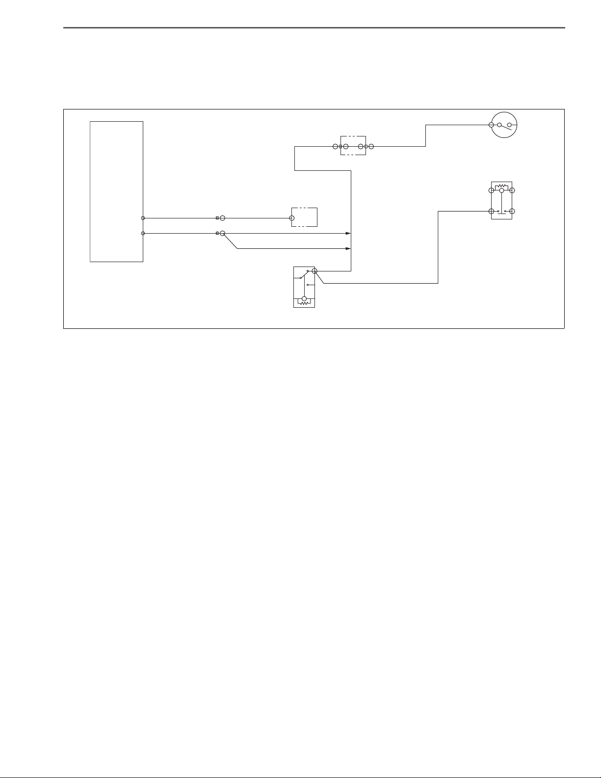
ENGINE CONTROL SYSTEM (J08E) 4–783
%L9
(STA)
K01
(S+)
K04
(NC)
NK0
(NO)
(ST)
N6E
(CL2-)
%L7
(STA)
ATM starter relay
Starter cut relay
Starter cut relay
LL1K01
K0G%D7
K0G
(STCR)
LL1
Engine
ECU
SAPH16F010300632
DTC: P081A
P081A: Starter Disable Circuit Low
INFORMATION
EN01H16F01030F03001098
1. Technical description
• The starter cut relay prevents further rotations of the starter when the starter switch is turned after start of the engine.
<Description of malfunction>
• Harness GND short-circuit or disconnection and relay unit failure are detected.
2. DTC set condition
(1) Check conditions
• Engine speed of 500 r/min or more. (Request starter cut relay operation)
• Starter switch ON.
• Battery voltage is in the range of 10 V to 16 V.
The conditions described above remain for 5 seconds or longer.
(2) Judgement criteria
• Output of the starter cut relay remains at 10 V or less for 3 seconds or longer.
3. Reset condition
• Just after restoration to normal condition.
4. Indication, warning or system control regulation when the DTC is set.
• MIL: OFF
• Diag lamp: OFF
5. Symptoms on the vehicle when the DTC is set
<Symptoms on the vehicle due to backup control (fail safe function)>
• –
<Symptoms on the vehicle due to malfunction>
• Starter operates even when the engine is running.
6. Pre-inspection work
• Check that the battery voltage is in the normal range.
Page 7

ENGINE CONTROL SYSTEM (J08E)4–784
7. After-inspection work
• Clear all past DTCs.
• Check that no DTC is stored after test drive.
8. Estimated failure factors
• Harness disconnection or short-circuit
• Looseness or poor contact of connector
• starter cut relay failure
• Engine ECU failure
Page 8

ENGINE CONTROL SYSTEM (J08E) 4–785
NOYES
NOYES
Select
Engine
SAPH16F010300633
INSPECTION PROCEDURE: P081A
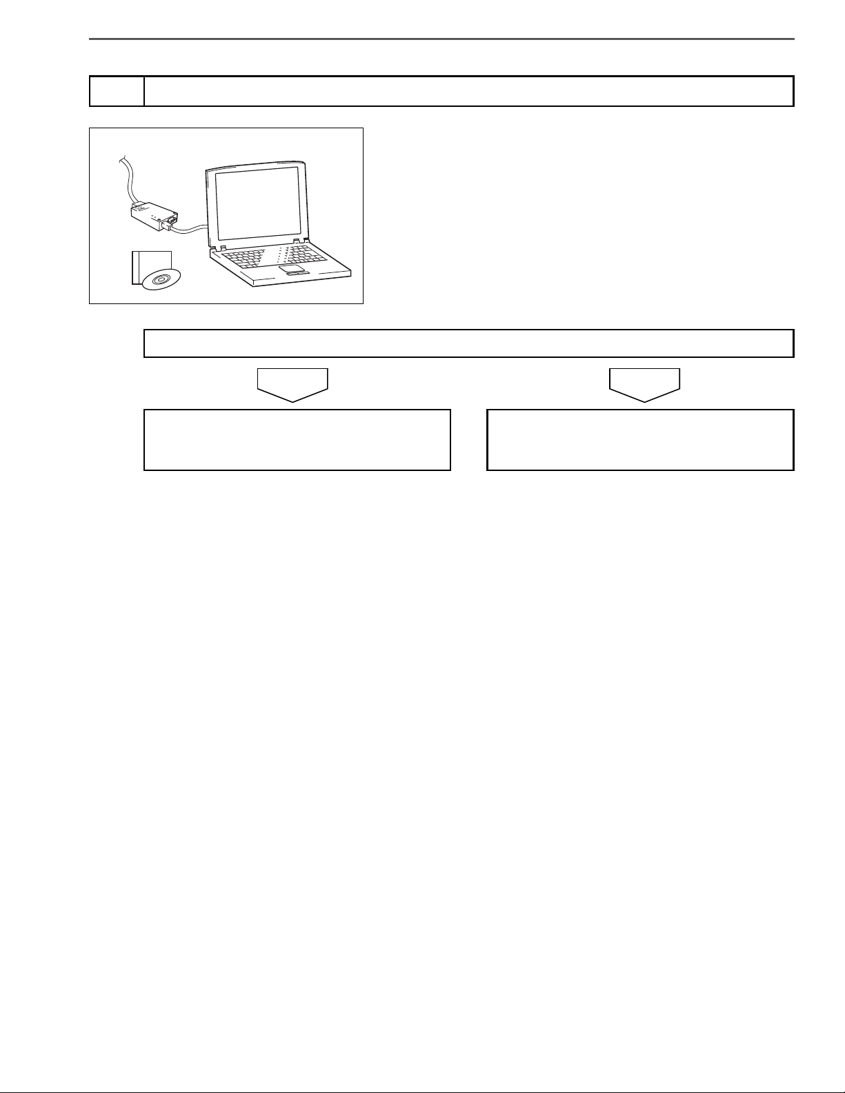
Check the DTC detected (Engine ECU) [Hino-DX]
1
Has DTC P081A been detected?
1. Set the starter switch to the "LOCK" position.
2. Disconnect the starter cut relay.
3. Set the starter switch to the "ON" position.
4. Select [Engine] and check if P081A has been detected in [Fault
Information].
Go to step 2. Replace the starter cut relay.
Perform "After-inspection work" of INFORMATION section.
Inspect the starter cut relay connector
2
1. Check the connection of the starter cut relay connector (Looseness and poor contact).
Was any failure found?
Connect securely, repair if needed.
Go to step 3.
Perform "After-inspection work" of INFORMATION section.
Page 9

ENGINE CONTROL SYSTEM (J08E)4–786
NOYES
NOYES
A B
V2
V80
SAPH16F010300634
SAPH16F010300635
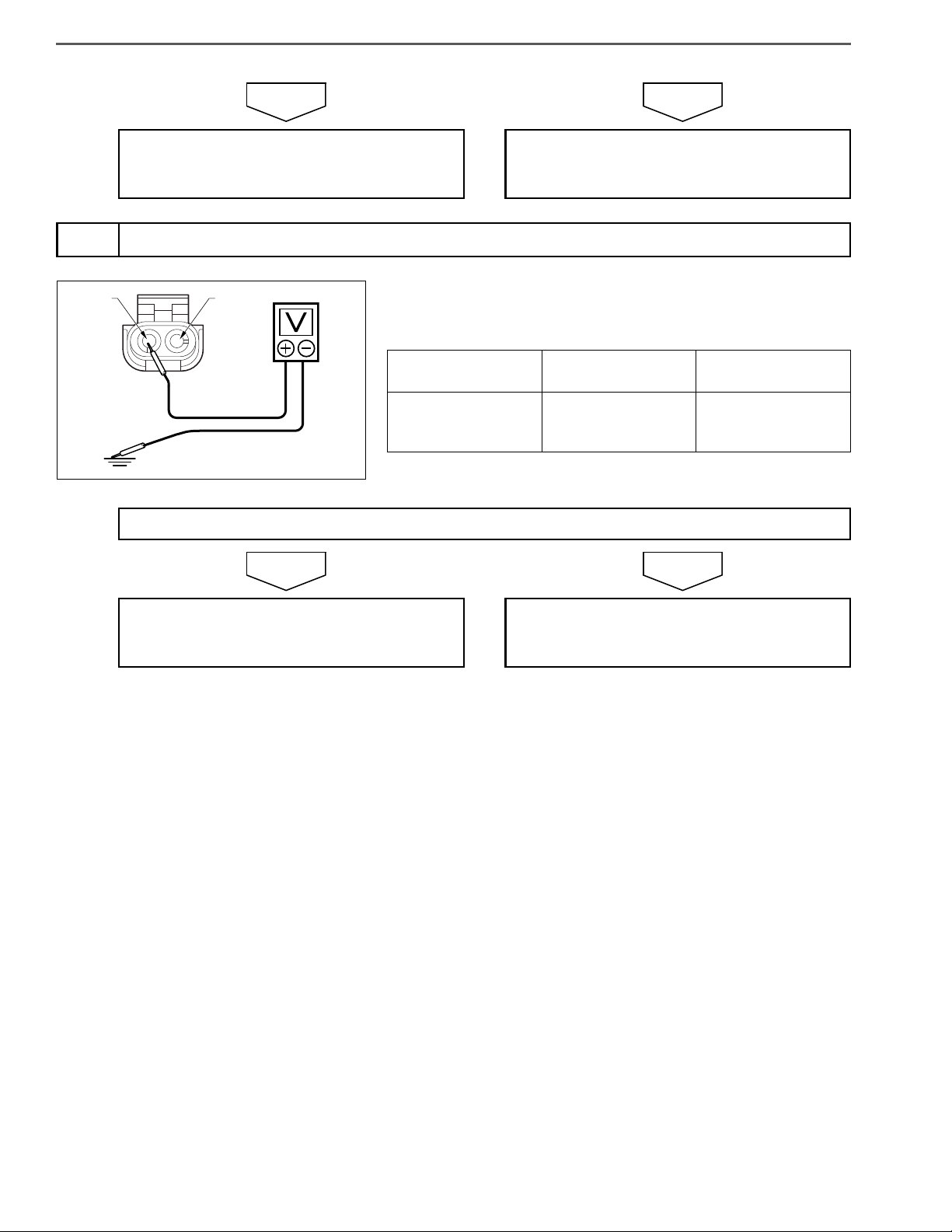
Inspect for disconnection in wire harness of starter cut relay
3
1. Set the starter switch to the "LOCK" position.
2. Connect the signal check harness to the engine ECU.
3. Set the starter switch to the "ON" position.
4. Use the electrical tester to measure the resistance between the
terminals of the engine ECU (signal check harness).
Measurement
conditions
Starter switch:
ON
Tester connections Standard values
Engine ECU (signal
check harness)
STCR(V2) – PGD4(V80)
Do the measurements meet the standard value?
Go to step 4. Repair or replace the harness.
Perform "After-inspection work" of INFORMATION section.
Check the DTC detected (Engine ECU) [Hino-DX]
4
1. Set the starter switch to the "ON" position.
2. Select [Engine] and check if P081A has been detected in [Fault
Information].
Has DTC P081A been detected?
Replace the engine ECU.
Perform "After-inspection work" of INFORMATION section.
Select
Engine
Procedure completed.
Perform "After-inspection work" of INFORMATION section.
Page 10

ENGINE CONTROL SYSTEM (J08E) 4–787
CHECKLIST: P081A
DTC: P081A Starter Disable Circuit Low Inspection procedure
Step Action Description Judgement
DTC P081A
has been
detected: Go
to YES.
No DTC has
Check the
DTC detected
1
(Engine ECU)
[Hino-DX]
1. Disconnect the starter cut
relay.
2. Check if P081A has been
detected in [Engine].
been detected:
Go to NO.
Failure found:
Inspect the
starter cut
2
relay connector
Check the connection of the
starter cut relay connector
(Looseness and poor contact).
Go to YES.
No failure
found: Go to
NO.
Inspect for disconnection in
3
wire harness
of starter cut
relay
Connect the signal check harness
to the engine ECU and measure
the resistance between the terminals of the engine ECU (signal
check harness).
<Tester connections>
Engine ECU (signal check harness)
STCR(V2) – PGD4(V80)
<Standard values>
The measure-
ments meet
the standard
value: Go to
YES.
The measure-
ments do not
meet the stan-
dard value: Go
to NO.
Check
(Yes/No)
Yes No
Go to step 2.
Connect
securely,
repair if
needed.
Perform "Afterinspection
work" of
INFORMATION section.
Go to step 4.
Replace the
starter cut
relay.
Perform "Afterinspection
work" of
INFORMATION section.
Go to step 3.
Repair or
replace the
harness.
Perform "Afterinspection
work" of
INFORMATION section.
Check the
DTC detected
4
(Engine ECU)
[Hino-DX]
Check if P081A has been
detected in [Engine].
DTC P081A
has been
detected. Go
to YES.
No DTC has
been detected.
Go to NO.
Replace the
engine ECU.
Perform "Afterinspection
work" of
INFORMATION section.
Procedure
completed.
Perform "Afterinspection
work" of
INFORMATION section.
Page 11

ENGINE CONTROL SYSTEM (J08E)4–788
%L9
(STA)
K01
(S+)
K04
(NC)
NK0
(NO)
(ST)
N6E
(CL2-)
%L7
(STA)
ATM starter relay
Starter cut relay
Starter cut relay
LL1K01
K0G%D7
K0G
(STCR)
LL1
Engine
ECU
SAPH16F010300636
DTC: P081B
P081B: Starter Disable Circuit High
INFORMATION
EN01H16F01030F03001099
1. Technical description
• The starter cut relay prevents further rotations of the starter when the starter switch is turned after start of the engine.
<Description of malfunction>
• Harness +B short-circuit is detected.
2. DTC set condition
(1) DTC detection condition
• Request for deactivation of starter block is in progress (while engine is stopped).
• Starter switch ON.
• Battery voltage is 10 V – 16 V.
Above conditions continue for at least 5 seconds.
(2) Judgement criteria
• Output of the starter cut relay remains at 10 V or more for 3 seconds or longer.
3. Reset condition
• After restoration to normal condition.
4. Indication, warning or system control regulation when the DTC is set.
• MIL: OFF
• Diag lamp: OFF
5. Symptoms on the vehicle when the DTC is set
<Symptoms on the vehicle due to backup control (fail safe function)>
• –
<Symptoms on the vehicle due to malfunction>
• Starter may not turn over. (If the starter turns over it will not interfere with engine operation.)
6. Pre-inspection work
• Check that the battery voltage is in the normal range.
Page 12

ENGINE CONTROL SYSTEM (J08E) 4–789
7. After-inspection work
• Clear all past DTCs.
• Check that no DTC is stored after test drive.
8. Estimated failure factors
• Harness disconnection or short-circuit
• Looseness or poor contact of connector
• Starter cut relay failure
• Engine ECU failure
Page 13

ENGINE CONTROL SYSTEM (J08E)4–790
NOYES
NOYES
A B
V2
V80
SAPH16F010300637
INSPECTION PROCEDURE: P081B
Inspect the starter cut relay connector
1
Was any failure found?
1. Check the connection of the starter cut relay connector (Looseness and poor contact).
Connect securely, repair if needed.
Perform "After-inspection work" of INFORMATION section.
Inspect for disconnection in wire harness of starter cut relay
2
1. Set the starter switch to the "LOCK" position.
2. Connect the signal check harness to the engine ECU.
3. Set the starter switch to the "ON" position.
4. Use the electrical tester to measure the resistance between the
terminals of the engine ECU (signal check harness).
Measurement
conditions
Starter switch:
ON
Do the measurements meet the standard value?
Go to step 2.
Tester connections Standard values
Engine ECU (signal
check harness)
STCR(V2) – PGD4(V80)
3 V or less
Go to step 3. Repair or replace the harness.
Perform "After-inspection work" of INFORMATION section.
Page 14
ENGINE CONTROL SYSTEM (J08E) 4–791
NOYES
Select
Engine
SAPH16F010300638
Check the DTC detected (Engine ECU) [Hino-DX]
3
1. Set the starter switch to the "ON" position.
2. Select [Engine] and check if P081B has been detected in [Fault
Has DTC P081B been detected?
Information].
Replace the engine ECU.
Perform "After-inspection work" of INFORMATION section.
Procedure completed.
Perform "After-inspection work" of INFORMATION section.
Page 15

ENGINE CONTROL SYSTEM (J08E)4–792
CHECKLIST: P081B
DTC: P081B Starter Disable Circuit High Inspection procedure
Step Action Description Judgement
Failure found:
Inspect the
starter cut
1
relay connector
Inspect for disconnection in
2
wire harness
of starter cut
relay
Check the
DTC detected
3
(Engine ECU)
[Hino-DX]
Check the connection of the
starter cut relay connector
(Looseness and poor contact).
Connect the signal check harness
to the engine ECU and measure
the resistance between the terminals of the engine ECU (signal
check harness).
<Tester connections>
Engine ECU (signal check harness)
STCR(V2) – PGD4(V80)
<Standard values>
3 V or less
Check if P081B has been
detected in [Engine].
Go to YES.
No failure
found: Go to
NO.
The measure-
ments meet
the standard
value: Go to
YES.
The measure-
ments do not
meet the stan-
dard value: Go
to NO.
DTC P081B
has been
detected: Go
to YES.
No DTC has
been detected:
Go to NO.
Check
(Yes/No)
Yes No
Connect
securely,
repair if
needed.
Perform "Afterinspection
work" of
INFORMATION section.
Go to step 3.
Replace the
engine ECU.
Perform "Afterinspection
work" of
INFORMATION section.
Go to step 2.
Repair or
replace the
harness.
Perform "Afterinspection
work" of
INFORMATION section.
Procedure
completed.
Perform "Afterinspection
work" of
INFORMATION section.
Page 16

ENGINE CONTROL SYSTEM (J08E) 4–793
SAPH16F010300639
DTC: P0850
P850: Neutral switch - rationality
INFORMATION
K45NRF
N1N
(NUSW)
Engine
ECU
K45
NRF
(-)
Neutral switch
#LH#LH
%DW
(NTSW)
NRE
(+)
NRE NRF
%G1
(NSIG)
%DX
(NTSW)
ON
OFF
#D4#D4
KSM
(SW+)
EN01H16F01030F03001100
Neutral switch
%17
(SIG)
Vehicle control ECU
L98
(NUSW)
A1J
(33LD)
DPR refresh switch
1. Technical description
• Through the neutral switch, the ECU senses neutral signals when the transmission lever is in the P or N range.
<Description of malfunction>
• The neutral switch cannot correctly sense.
2. DTC set condition
(1) Check conditions
After the starter switch is set to ON position, the status described below remains for 10 seconds.
• Vehicle speed is 31.25 miles/h or higher.
• Battery voltage is in the range of 10 V to 16 V.
• After that, vehicle speed is 0 miles/h.
(2) Judgement criteria
• The neutral switch cannot be switched twice.
3. Reset condition
• Immediately after normal operation is restored.
4. Indication, warning or system control regulation when the DTC is set.
• MIL: ON
• Diag lamp: OFF
• Cruise control is not available.
Page 17

ENGINE CONTROL SYSTEM (J08E)4–794
5. Symptoms on the vehicle when the DTC is set
<Symptoms on the vehicle due to backup control (fail safe function)>
• Cruise control does not work.
<Symptoms on the vehicle due to malfunction>
• –
6. Pre-inspection work
• Check that the battery voltage is in the normal range.
7. After-inspection work
• Clear all past DTCs.
• Check that no DTC is stored after test drive.
8. Estimated failure factors
• Harness disconnection or short-circuit
• Malfunction of neutral switch
• Malfunction of ECU
Page 18

ENGINE CONTROL SYSTEM (J08E) 4–795
NOYES
NOYES
NRF(-) NRE(+)
SAPH16F010300640
INSPECTION PROCEDURE: P0850
Inspect the neutral switch
1
Was any failure found?
1. Check if the neutral switch is properly adjusted.
Adjust the neutral switch.
Perform "After-inspection work" of INFORMATION section.
Inspect the neutral switch connector
2
Was any failure found?
Connect securely, repair if needed.
Perform "After-inspection work" of INFORMATION section.
Inspect the neutral switch unit
3
Go to step 2.
1. Check the connection of the neutral switch connector (Looseness
and poor contact).
Go to step 3.
1. Set the starter switch to the "LOCK" position.
Do the measurements meet the standard value?
2. Disconnect the neutral switch connector.
3. Use the electrical tester to measure the resistance between the
terminals of the neutral switch.
Measurement
conditions
Starter switch:
LOCK
Tester connections Standard values
Shift lever in N posiNeutral switch
NRE – NRF
tion: < 1
Shift lever in any
other position:
Page 19
ENGINE CONTROL SYSTEM (J08E)4–796
NOYES
NOYES
NRE(+) NRF(-)
SAPH16F010300641
Go to step 4. Replace the neutral switch.
Perform "After-inspection work" of INFORMATION section.
Inspect the power supply of the neutral switch
4
1. Set the starter switch to the "ON" position.
2. Use the electrical tester to measure the voltage between the NRE
terminal in the neutral switch vehicle-side connector and ground.
Measurement
conditions
Starter switch: ON
Tester connections Standard values
Neutral switch vehicle-side connector
NRE – Ground
More than 10 V
Do the measurements meet the standard value?
Go to step 5. Repair the neutral switch power circuit.
Perform "After-inspection work" of INFORMATION section.
Page 20

NOYES
Inspect the neutral switch harness
A
V11
SAPH16F010300642
5
ENGINE CONTROL SYSTEM (J08E) 4–797
1. Set the starter switch to the "LOCK" position.
2. Connect the neutral switch connector.
3. Connect the signal check harness to the engine ECU vehicle-side
harness. (Do not connect the harness to the ECU.)
4. Set the starter switch to the "ON" position.
5. Use the electrical tester to measure the voltage between the terminals of the engine ECU (signal check harness) and ground.
Measurement
conditions
Starter switch:
ON
Do the measurements meet the standard value?
Replace the engine ECU.
Perform "After-inspection work" of INFORMATION section.
Tester connections Standard values
Engine ECU (signal
check harness)
NUSW(V11) – Ground
Shift lever in N position: ≥ 10 V
Shift lever in any
other position: ≤ 0.5 V
Repair or replace the harness.
Perform "After-inspection work" of INFORMATION section.
Page 21

ENGINE CONTROL SYSTEM (J08E)4–798
CHECKLIST: P0850
DTC: P0850 Neutral switch - rationality Inspection procedure
Step Action Description Judgement
Failure found:
Go to YES.
Inspect the
1
neutral switch
Inspect the
2
neutral switch
connector
Inspect the
3
neutral switch
unit
Check if the neutral switch is
properly adjusted.
Check the connection of the neutral switch connector (Looseness
and poor contact).
Measure the resistance between
the terminals of the neutral
switch.
<Tester connections>
Neutral switch
NRE – NRF
<Standard values>
Shift lever in N position: < 1
Shift lever in any other position:
No failure
found: Go to
NO.
Failure found:
Go to YES.
No failure
found: Go to
NO.
The measurements meet
the standard
value: Go to
YES.
The measurements do not
meet the standard value: Go
to NO.
Check
(Yes/No)
Yes No
Adjust the
neutral switch.
Perform "Afterinspection
work" of
INFORMATION section.
Connect
securely.
repair if
needed.
Perform "Afterinspection
work" of
INFORMATION section.
Go to step 4.
Go to step 2.
Go to step 3.
Replace the
neutral switch.
Perform "Afterinspection
work" of
INFORMATION section.
Inspect the
power supply
4
of the neutral
switch
Measure the voltage between the
NRE terminal in the neutral switch
vehicle-side connector and
ground.
<Tester connections>
Neutral switch vehicle-side connector
NRE – Ground
<Standard values>
More than 10 V
The measurements meet
the standard
value: Go to
YES.
The measurements do not
meet the standard value: Go
to NO.
Go to step 5.
Repair the
neutral switch
power circuit.
Perform "Afterinspection
work" of
INFORMATION section.
Page 22

ENGINE CONTROL SYSTEM (J08E) 4–799
DTC: P0850 Neutral switch - rationality Inspection procedure
Step Action Description Judgement
1. Connect the neutral switch
connector.
Inspect the
5
neutral switch
harness
2. Connect the signal check
harness, and measure the
voltage between the terminals of the engine ECU (signal check harness) and
ground.
<Tester connections>
Engine ECU (signal check harness)
NUSW(V11) – Ground
<Standard values>
The measurements meet
the standard
value: Go to
YES.
The measurements do not
meet the standard value: Go
to NO.
Shift lever in N position: ≥ 10 V
Shift lever in any other position: ≤
0.5 V
Check
(Yes/No)
Yes No
Replace the
engine ECU.
Perform "Afterinspection
work" of
INFORMATION section.
Repair or
replace the
harness.
Perform "Afterinspection
work" of
INFORMATION section.
Page 23

ENGINE CONTROL SYSTEM (J08E)4–800
SAPH16F010300643
DTC: P1133
P1133: PTO accelerator sensor (Hi)
INFORMATION
PTO
accelerator sensor
(VCC)
K95
Exhaust gas
temperature
sensor
(DOC outlet)
KSE
(TEX1)
KSF
(GND1)
Differential
pressure
sensor
KSJ
(VCC)
KSK
(VOUT)
KSL
(GND)
EN01H16F01030F03001101
Exhaust gas
temperature
sensor
(DOC inlet)
LCY
(TEX3)
LCZ
(GND3)
KSE KR4
KSE KR4
LCG
(ET4+)
KSJ KUQ
KSJ KUQ
KUQ
(AVC5)
KSK KUH
KSK KUH
KUH
(EXPS)
KSF LCT
KSF LCT
LCT
(ADG9)
Engine
ECU
LCY LCG
LCY LCG
KR4
(ET2+)
1. Technical description
• The operational accelerator sensor measures accelerator opening if PTO (power take off) is used. (This applies only
to PTO-equipped vehicles.)
<Description of malfunction>
• The operational accelerator sensor cannot correctly sense.
• +B short-circuit is likely to have occurred.
2. DTC set condition
(1) Check conditions
• Starter switch ON.
• Battery voltage is in the range of 10 V to 16 V.
The conditions described above remain for 5 seconds or longer.
(2) Judgement criteria
• Sensor voltage remains at 4.82 V or higher for 3 seconds or longer.
3. Reset condition
• After normal operation is restored and starter switch is turned LOCK.
Page 24

ENGINE CONTROL SYSTEM (J08E) 4–801
4. Indication, warning or system control regulation when the DTC is set.
• MIL: OFF
• Diag lamp: OFF
• Body mounting control is not available.
5. Symptoms on the vehicle when the DTC is set
<Symptoms on the vehicle due to backup control (fail safe function)>
• Body mounting control is not working.
<Symptoms on the vehicle due to malfunction>
• –
6. Pre-inspection work
• Check that the battery voltage is in the normal range.
7. After-inspection work
• Clear all past DTCs.
• Check that no DTC is stored after test drive.
8. Estimated failure factors
• Faulty harness (+B short-circuit)
• Malfunction of sensor
• Failure in engine ECU sensor power supply or internal circuit
Page 25

ENGINE CONTROL SYSTEM (J08E)4–802
NOYES
NOYES
INSPECTION PROCEDURE: P1133
Inspect the PTO accelerator sensor connector
1
Was any failure found?
1. Check the connection of the PTO accelerator sensor connector
(Looseness and poor contact).
Connect securely, repair if needed.
Perform "After-inspection work" of INFORMATION section.
Inspect the PTO accelerator sensor
2
Was any failure found?
Clean the PTO accelerator sensor and install
it properly.
If damaged, replace the sensor.
Perform "After-inspection work" of INFORMATION section.
Go to step 2.
1. Check the installation of the PTO accelerator sensor.
2. Make sure there is no dirt or damage to the PTO accelerator sensor.
Go to step 3.
Page 26

ENGINE CONTROL SYSTEM (J08E) 4–803
NOYES
VCCSIG
GND
SIG
SAPH16F010300644
Inspect the PTO accelerator sensor unit
3
1. Set the starter switch to the "LOCK" position.
2. Disconnect the PTO accelerator sensor connector.
3. Use the electrical tester to measure the resistance between the
terminals of the PTO accelerator sensor.
Measurement
conditions
Tester connections Standard values
PTO accelerator
Starter switch:
LOCK
sensor
SIG – VCC
More than 2
SIG – GND
Do the measurements meet the standard value?
Go to step 4. Replace the PTO accelerator sensor.
Perform "After-inspection work" of INFORMATION section.
Page 27

ENGINE CONTROL SYSTEM (J08E)4–804
NOYES
B
B
V71
V68
V45
SAPH16F010300645
Inspect for short-circuit of the PTO accelerator sensor harness
4
1. Connect the signal check harness to the engine ECU. (Do not connect the harness to the ECU.)
2. Use the electrical tester to measure the resistance between the
terminals of the engine ECU (signal check harness) and ground.
Measurement
conditions
Starter switch:
LOCK
Tester connections Standard values
Engine ECU (signal
check harness)
ASCS(V68) – Ground
AVC5(V71) – Ground
ADG7(V45) – Ground
Do the measurements meet the standard value?
Go to step 5. Repair or replace the harness.
Perform "After-inspection work" of INFORMATION section.
Page 28

ENGINE CONTROL SYSTEM (J08E) 4–805
NOYES
NOYES
B
B
V45
V68
V71
V68
SAPH16F010300646
Select
Engine
SAPH16F010300647
Inspect disconnection of the PTO accelerator sensor harness
5
1. Connect the PTO accelerator sensor connector.
2. Use the electrical tester to measure the resistance between the
terminals of the engine ECU (signal check harness).
Measurement
conditions
Starter switch:
LOCK
Tester connections Standard values
Engine ECU (signal
check harness)
ASCS(V68) – AVC5(V71)
ASCS(V68) – ADG7(V45)
More than 2
Do the measurements meet the standard value?
Go to step 6. Repair or replace the harness.
Perform "After-inspection work" of INFORMATION section.
Check the DTC detected (Engine ECU) [Hino-DX]
6
1. Connect the vehicle to Hino-DX.
2. Set the starter switch to the "ON" position.
3. Select [Engine] and check if P1133 has been detected in [Fault
Has DTC P1133 been detected?
Replace the engine ECU.
Perform "After-inspection work" of INFORMATION section.
Information].
Procedure completed.
Perform "After-inspection work" of INFORMATION section.
Page 29

ENGINE CONTROL SYSTEM (J08E)4–806
CHECKLIST: P1133
DTC: P1133 PTO accelerator sensor (Hi) Inspection procedure
Step Action Description Judgement
Failure found:
Inspect the
PTO accelera-
1
tor sensor connector
Check the connection of the PTO
accelerator sensor connector
(Looseness and poor contact).
Go to YES.
No failure
found: Go to
NO.
Inspect the
2
PTO accelerator sensor
1. Check the installation of the
PTO accelerator sensor.
2. Make sure there is no dirt or
damage to the PTO accelerator sensor.
Failure found:
Go to YES.
No failure
found: Go to
NO.
Check
(Yes/No)
Yes No
Connect
securely,
repair if
needed.
Perform "Afterinspection
work" of
INFORMATION section.
Clean the PTO
accelerator
sensor and
install it properly.
If damaged,
replace the
sensor.
Perform "Afterinspection
work" of
INFORMATION section.
Go to step 2.
Go to step 3.
Inspect the
3
PTO accelerator sensor unit
Inspect for
short-circuit of
4
the PTO accelerator sensor
harness
Disconnect the PTO accelerator
sensor connector and measure
the resistance between the terminals of the PTO accelerator sensor.
<Tester connections>
PTO accelerator sensor
SIG – VCC
SIG – GND
<Standard values>
More than 2
Connect the signal check harness
to the engine ECU. (Do not connect harness to the ECU.)
Measure the resistance between
the terminals of the engine ECU
(signal check harness) and
ground.
<Tester connections>
Engine ECU (signal check harness)
ASCS(V68) – Ground
AVC5(V71) – Ground
<Standard values>
The measurements meet
the standard
value: Go to
YES.
The measurements meet
the standard
value: Go to
YES.
The measurements do not
meet the standard value: Go
to NO.
Go to step 4.
Go to step 5.
Replace the
sensor.
Perform "Afterinspection
work" of
INFORMATION section.
Repair or
replace the
harness.
Perform "Afterinspection
work" of
INFORMATION section.
Page 30

ENGINE CONTROL SYSTEM (J08E) 4–807
DTC: P1133 PTO accelerator sensor (Hi) Inspection procedure
Step Action Description Judgement
The measurements meet
the standard
value: Go to
YES.
The measurements do not
meet the standard value: Go
to NO.
DTC P1133
has been
detected: Go
to YES.
No DTC has
been detected:
Go to NO.
Inspect disconnection of
5
the PTO accelerator sensor
harness
Check the
DTC detected
6
(Engine ECU)
[Hino-DX]
Connect the PTO accelerator
sensor connector and measure
the resistance between the terminals of the engine ECU (signal
check harness).
<Tester connections>
ASCS(V68) – AVC5(V71)
ASCS(V68) – ADG7(V45)
<Standard values>
More than 2
Check if P1133 has been
detected in [Engine].
Check
(Yes/No)
Yes No
Go to step 6.
Replace the
engine ECU.
Perform "Afterinspection
work" of
INFORMATION section.
Repair or
replace the
harness.
Perform "Afterinspection
work" of
INFORMATION section.
Procedure
completed.
Perform "Afterinspection
work" of
INFORMATION section.
Page 31

ENGINE CONTROL SYSTEM (J08E)4–808
SAPH16F010300648
DTC: P119F
P119F: Fuel rail pressure sensor - rationality
INFORMATION
K8N (PCR-)
GND1
K8P (PCR)
Common rail
pressure sensor
PCR-
PCR-
K8N
PCR-
K8N
K8N
PCR-
K8N
PCR-
K8N
PCR-
K8N
SIG1
VCC1
GND2
SIG2
VCC2
K8M (PCR+)
LLK (PCR-)
LLH (PCR)
LLJ (PCR+)
Common rail
Pressure limiter
Flow damper
K6D
KRX
K6E
KRP
KRY
LL3
KRQ
LCE
Pressure sensor
(PCR1)
(AGD1)
(PCR2)
(AVC1)
(AGD2)
(PCR4)
(AVC2)
(PCR3)
EN01H16F01030F03001102
Engine
ECU
1. Technical description
• The common rail pressure sensor consistently measures common rail pressure.
<Description of malfunction>
• Common rail pressure cannot be correctly sensed.
• Malfunction is likely to have occurred in the common rail pressure sensor.
2. DTC set condition
(1) Check conditions
• Starter switch ON.
• Battery voltage is in the range of 10 V to 16 V.
• The conditions described above remain for 5 seconds or longer.
• Common rail pressure is 220 MPa or less.
• No other diagnosis codes are present (the monitor disable DTC table can be referred to)
(2) Judgement criteria
P119F is detected under the conditions described below. 1 and 2 represent the order of priority.
1. A difference in voltage remains higher than 1.06 V for 3 seconds or longer.
2. A difference in voltage remains less than 0.04 V for 3 seconds or longer.
3. Reset condition
• After normal operation is restored and starter switch LOCK.
4. Indication, warning or system control regulation when the DTC is set.
• MIL: ON
• Diag lamp: OFF
5. Symptoms on the vehicle when the DTC is set
<Symptoms on the vehicle due to backup control (fail safe function)>
• –
Page 32

ENGINE CONTROL SYSTEM (J08E) 4–809
<Symptoms on the vehicle due to malfunction>
• –
6. Pre-inspection work
• Check that the battery voltage is in the normal range.
7. After-inspection work
• Clear all past DTCs.
• Check that no DTC is stored after test drive.
8. Estimated failure factors
• Sensor disconnected from measuring site
• Harness disconnection or short-circuit
• Abnormal resistance of sensor
• Malfunction of ECU
Page 33

ENGINE CONTROL SYSTEM (J08E)4–810
NOYES
NOYES
SAPH16F010300649
INSPECTION PROCEDURE: P119F
Check the DTC detected 1 (Engine ECU) [Hino-DX]
1
1. Set the starter switch to the "LOCK" position.
2. Connect the vehicle to Hino-DX.
Select
Engine
3. Set the starter switch to the "ON" position.
4. Select [Engine] and check if any DTC other than P119F (for example, P0192, P0193) have been detected in [Fault Information].
Has a DTC other than P119F been detected?
Go to the diagnostic procedure of a related
DTC.
Inspect the common rail pressure sensor connector
2
1. Check the connection of the common rail pressure sensor connector (Looseness and poor contact).
Go to step 2.
Was any failure found?
Connect securely, repair if needed.
Perform "After-inspection work" of INFORMATION section.
Go to step 3.
Page 34

NOYES
Inspect the sensor power supply
C D
D
E13
E33 E76
E56
E49
E56
E68
E64
E76
E65
SAPH16F010300650
3
ENGINE CONTROL SYSTEM (J08E) 4–811
1. Set the starter switch to the "LOCK" position.
2. Connect the signal check harness to the engine ECU.
3. Disconnect the common rail pressure sensor connector.
4. Set the starter switch to the "ON" position.
5. Use the electrical tester to measure the voltage between the terminals of the engine ECU (signal check harness).
Measurement
conditions
Tester connections Standard values
Engine ECU (signal
check harness)
AVC1(E13) – AGD1(E56)
Starter switch:
ON
PCR1(E49) – AGD1(E56)
PCR2(E68) – AGD1(E56)
AVC2(E33) – AGD2(E76)
PCR3(E64) – AGD2(E76)
PCR4(E65) – AGD2(E76)
Do the measurements meet the standard value?
Go to step 4. Replace the engine ECU.
Perform "After-inspection work" of INFORMATION section.
4.5 – 5.5 V
Page 35

ENGINE CONTROL SYSTEM (J08E)4–812
NOYES
NOYES
D
E49
E68
E65
E64
SAPH16F010300651
Select
Engine
SAPH16F010300652
Inspect the signal of the common rail pressure sensor
4
1. Set the starter switch to the "LOCK" position.
2. Connect the common rail pressure sensor connector.
3. Set the starter switch to the "ON" position.
4. Use the electrical tester to measure the voltage between the terminals of the engine ECU (signal check harness).
Measurement
conditions
Tester connections Standard values
Engine ECU (signal
check harness)
Starter switch:
ON
PCR1(E49) – PCR3(E64)
PCR1(E49) – PCR4(E65)
0.3 – 0.7 V
PCR2(E68) – PCR3(E64)
PCR2(E68) – PCR4(E65)
Do the measurements meet the standard value?
Go to step 5. Replace the common rail pressure sensor.
Perform "After-inspection work" of INFORMATION section.
Check the DTC detected 2(Engine ECU) [Hino-DX]
5
1. Perform engine warm-up. (engine coolant temperature: 60 C {140
F} or more)
Has DTC P119F been detected?
Replace the engine ECU.
Perform "After-inspection work" of INFORMATION section.
2. Stop the engine and set the starter switch to the "ON" position.
3. Select [Engine] and check if P119F has been detected in [Fault
Information].
Procedure completed.
Perform "After-inspection work" of INFORMATION section.
Page 36

ENGINE CONTROL SYSTEM (J08E) 4–813
CHECKLIST: P119F
DTC: P119F Fuel rail pressure sensor - rationality Inspection procedure
Step Action Description Judgement
DTC other
than P119F
has been
Check the
DTC detected
1
1 (Engine
ECU) [HinoDX]
Check if any DTC other than
P119F (for example P0192,
P0193) has not been detected in
[Engine].
detected: Go
to YES.
DTC other
than P119F
has not been
detected: Go
to NO.
Failure found:
Inspect the
common rail
2
pressure sensor connector
Check the connection of the common rail pressure sensor connector (Looseness and poor contact).
Go to YES.
No failure
found: Go to
NO.
1. Connect the signal check
harness to the engine and
disconnect the common rail
pressure sensor connector.
The measurements meet
the standard
value: Go to
YES.
The measurements do not
meet the standard value: Go
to NO.
Inspect the
3
sensor power
supply
2. Measure the voltage
between the terminals of the
engine ECU (signal check
harness).
<Tester connections>
Engine ECU (signal check harness)
AVC1(E13) – AGD1(E56)
PCR1(E49) – AGD1(E56)
PCR2(E68) – AGD1(E56)
AVC2(E33) – AGD2(E76)
PCR3(E64) – AGD2(E76)
PCR4(E65) – AGD2(E76)
<Standard values>
4.5 – 5.5 V
Check
(Yes/No)
Yes No
Go to the diagnostic procedure of a
related DTC.
Connect
securely,
repair if
needed.
Perform "Afterinspection
work" of
INFORMATION section.
Go to step 4.
Go to step 2.
Go to step 3.
Replace the
engine ECU.
Perform "Afterinspection
work" of
INFORMATION section.
Page 37

ENGINE CONTROL SYSTEM (J08E)4–814
DTC: P119F Fuel rail pressure sensor - rationality Inspection procedure
Step Action Description Judgement
Connect the common rail pres-
Inspect the
signal of the
4
common rail
pressure sensor
sure sensor connector and measure the voltage between the
terminals of the engine ECU (signal check harness).
<Tester connections>
Engine ECU (signal check harness)
PCR1(E49) – PCR3(E64)
PCR1(E49) – PCR4(E65)
PCR2(E68) – PCR3(E64)
PCR2(E68) – PCR4(E65)
<Standard values>
The measurements meet
the standard
value: Go to
YES.
The measurements do not
meet the standard value: Go
to NO.
0.3 – 0.7 V
DTC P119F
has been
detected: Go
to YES.
No DTC has
been detected:
Check the
DTC detected
5
2 (Engine
ECU) [HinoDX]
1. Perform engine warm-up.
(engine coolant temperature: 60 C {140 F} or more)
2. Check if P119F has been
detected in [Engine].
Go to NO.
Check
(Yes/No)
Yes No
Go to step 5.
Replace the
engine ECU.
Perform "Afterinspection
work" of
INFORMATION section.
Replace the
sensor.
Perform "Afterinspection
work" of
INFORMATION section.
Procedure
completed.
Perform "Afterinspection
work" of
INFORMATION section.
Page 38

ENGINE CONTROL SYSTEM (J08E) 4–815
DTC: P141F
P141F: Burner system malfunction
INFORMATION
1. Technical description
• Malfunction in the burner system is diagnosed by BCU.
• Determine system in the BCU and diagnose malfunction on Hino-DX.
<Description of malfunction>
• BCU detects burner system failure.
2. DTC set condition
(1) Check conditions
• –
(2) Judgement criteria
• –
3. Reset condition
• Immediately after normal operation is restored.
4. Indication, warning or system control regulation when the DTC is set.
• MIL: ON
• Diag lamp: OFF
• Engine output is restricted.
EN01H16F01030F03001103
5. Symptoms on the vehicle when the DTC is set
<Symptoms on the vehicle due to backup control (fail safe function)>
• Engine output is insufficient.
<Symptoms on the vehicle due to malfunction>
• –
6. Pre-inspection work
• Check that the battery voltage is in the normal range.
7. After-inspection work
• Clear all past DTCs.
• Check that no DTC is detected after test drive.
8. Estimated failure factors
• –
Page 39

ENGINE CONTROL SYSTEM (J08E)4–816
NOYES
Select
Engine
SAPH16F010300653
INSPECTION PROCEDURE: P141F
Check the DTC detected (Engine ECU) [Hino-DX]
1
Has DTC P141F been detected?
1. Set the starter switch to the "LOCK" position.
2. Connect the vehicle to Hino-DX.
3. Set the starter switch to the "ON" position.
4. Select [Engine] and check if P141F has been detected in [Fault
Information].
Go to DTC separate trouble diagnosis of the
burner system (BCU).
Procedure completed.
Perform "After-inspection work" of INFORMATION section.
Page 40

ENGINE CONTROL SYSTEM (J08E) 4–817
CHECKLIST: P141F
DTC: P141F Burner system malfunction Inspection procedure
Step Action Description Judgement
DTC P141F
has been
Check the
DTC detected
1
(Engine ECU)
[Hino-DX]
Check if P141F has been
detected in [Engine].
detected: Go
to YES.
No DTC has
been detected:
Go to NO.
Check
(Yes/No)
Yes No
Go to DTC
separate trouble diagnosis
of the burner
system (BCU).
Procedure
completed.
Perform "Afterinspection
work" of
INFORMATION section.
Page 41

ENGINE CONTROL SYSTEM (J08E)4–818
(ET4+)
(ET2+)
(EXPS)
(ADG9)
(AVC5)
KR4
(GND3)
(TEX3)
KUH
LCT
KUQ
(VOUT)
(GND)
KSK
KSL
(VCC)
KSJ
LCY
LCZ
LCY LCG
KSF LCT
KSK KUH
KSJ KUQ
KSE KR4
LCY LCG
KSF LCT
KSK KUH
KSJ KUQ
KSE KR4
(GND1)
(TEX1)
KSE
KSF
Differential
pressure
sensor
LCG
Exhaust gas
temperature
sensor
(DOC outlet)
Exhaust gas
temperature
sensor
(DOC inlet)
Engine
ECU
SAPH16F010300654
DTC: P1426
P1426: Differential pressure sensor - rationality
INFORMATION
EN01H16F01030F03001104
1. Technical description
• It detects a difference between pressure at the inlet of the muffler and atmospheric pressure and monitors any failure
or malfunction of the DPR.
<Description of malfunction>
• DPR differential pressure sensor is recognized as being stuck or in characteristics failure condition.
2. DTC set condition
(1) Check conditions
• Elapse of at least 2 seconds after engine stop
• No other DTCs are present.
(2) Judgement criteria
• Differential pressure remains less than -2 kPa {-0.3 psi} or higher than +2 kPa {+0.3 psi} for 2 seconds.
3. Reset condition
• Immediately after normal operation is restored.
4. Indication, warning or system control regulation when the DTC is set.
• MIL: ON
• Diag lamp: OFF
5. Symptoms on the vehicle when the DTC is set
<Symptoms on the vehicle due to backup control (fail safe function)>
• –
Page 42

ENGINE CONTROL SYSTEM (J08E) 4–819
<Symptoms on the vehicle due to malfunction>
• –
6. Pre-inspection work
• Check that the battery voltage is in the normal range.
7. After-inspection work
• Clear all past DTCs.
• Check that no DTC is stored after test drive.
8. Estimated failure factors
• Loose/disconnected sensor and failure in sensing area (contamination or clogging)
• Abnormality in resistance of sensor
• Malfunction of engine ECU sensor power supply or internal circuit
Page 43

ENGINE CONTROL SYSTEM (J08E)4–820
NOYES
NOYES
NOYES
INSPECTION PROCEDURE: P1426
Check the differential pressure hose and pipe
1
Was any failure found?
1. Check if the differential pressure hose and pipe are cracked, bent,
ruptured, or clogged.
Clean or replace the differential pressure
hose and pipe.
Perform "After-inspection work" of INFORMATION section.
Inspect the differential pressure sensor connector
2
1. Check the connection of the differential pressure sensor connector
Was any failure found?
Connect securely, repair if needed.
Perform "After-inspection work" of INFORMATION section.
Inspect the differential pressure sensor
3
Go to step 2.
(Looseness and poor contact).
Go to step 3.
1. Check the installation of the differential pressure sensor.
2. Make sure there is no dirt or damage to the differential pressure
sensor.
Was any failure found?
Clean the differential pressure sensor and
install it properly.
If damaged, replace the differential pressure
sensor.
Perform "After-inspection work" of INFORMATION section.
Go to step 4.
Page 44

ENGINE CONTROL SYSTEM (J08E) 4–821
NOYES
GND
VCC
GND
VOUT
SAPH16F010300655
B
V70
V71
V46
SAPH16F010300656
Inspect the differential pressure sensor unit
4
1. Set the starter switch to the "LOCK" position.
2. Disconnect the DPR differential pressure sensor connector.
3. Use the electrical tester to measure the resistance between the
terminals of the differential pressure sensor.
Measurement
conditions
Tester connections Standard values
Differential presStarter switch:
LOCK
sure sensor
VCC – GND
2 – 15 k
VOUT – GND
Do the measurements meet the standard value?
Go to step 5. Replace the differential pressure sensor.
Perform "After-inspection work" of INFORMATION section.
Inspect for short-circuit of the differential pressure sensor harness
5
1. Set the starter switch to the "LOCK" position.
2. Connect the signal check harness to the engine ECU vehicle-side
harness. (Do not connect the harness to the ECU.)
3. Use the electrical tester to measure the resistance between the
terminals of the engine ECU (signal check harness) and ground.
Measurement
conditions
Engine ECU (signal
Starter switch:
LOCK
check harness)
AVC5(V71) – Ground
EXPS(V70) – Ground
AGD9(V46) – Ground
Do the measurements meet the standard value?
Tester connections Standard values
Page 45

ENGINE CONTROL SYSTEM (J08E)4–822
NOYES
NOYES
B
B
V70
V71
V70
V46
SAPH16F010300657
Go to step 6. Repair or replace the harness.
Perform "After-inspection work" of INFORMATION section.
Inspect disconnection of the differential pressure sensor harness
6
1. Connect the differential pressure sensor connector.
2. Use the electrical tester to measure the resistance between the
terminals of the engine ECU (signal check harness).
Measurement
conditions
Starter switch:
LOCK
Tester connections Standard values
Engine ECU (signal
check harness)
AVC5(V71) – EXPS(V70)
AGD9(V46) – EXPS(V70)
2 – 15 k
Do the measurements meet the standard value?
Go to step 7. Repair or replace the harness.
Perform "After-inspection work" of INFORMATION section.
Page 46

ENGINE CONTROL SYSTEM (J08E) 4–823
NOYES
Select
Engine
SAPH16F010300658
Check the DTC detected (Engine ECU) [Hino-DX]
7
1. Perform engine warm-up. (engine coolant temperature: 60 C {140
2. Stop the engine and set the starter switch to the "LOCK" position.
3. Connect the vehicle to Hino-DX.
4. Set the starter switch to the "ON" position.
5. Select [Engine] and check if P1426 has been detected in [Fault
Has DTC P1426 been detected?
F} or more)
Information].
Replace the engine ECU.
Perform "After-inspection work" of INFORMATION section.
Procedure completed.
Perform "After-inspection work" of INFORMATION section.
Page 47

ENGINE CONTROL SYSTEM (J08E)4–824
CHECKLIST: P1426
DTC: P1426 Differential pressure sensor - rationality Inspection procedure
Step Action Description Judgement
Failure found:
Check the differential pres-
1
sure hose and
pipe
Check if the differential pressure
hose and pipe are cracked, bent,
ruptured, or clogged.
Go to YES.
No failure
found: Go to
NO.
Failure found:
Inspect the differential pres-
2
sure sensor
connector
Check the connection of the differential pressure sensor connector (Looseness and poor contact).
Go to YES.
No failure
found: Go to
NO.
Inspect the dif-
3
ferential pressure sensor
1. Check the installation of the
differential pressure sensor.
2. Make sure there is no dirt or
damage to the differential
pressure sensor.
Failure found:
Go to YES.
No failure
found: Go to
NO.
Check
(Yes/No)
Yes No
Clean or
replace the differential pressure hose and
pipe.
Perform "Afterinspection
work" of
INFORMATION section.
Connect
securely,
repair if
needed.
Perform "Afterinspection
work" of
INFORMATION section.
Clean the differential pressure sensor
and install it
properly.
If damaged,
replace the
sensor.
Perform "Afterinspection
work" of
INFORMATION section.
Go to step 2.
Go to step 3.
Go to step 4.
Inspect the differential pres-
4
sure sensor
unit
Disconnect the DPR differential
pressure sensor connector and
measure the resistance between
the terminals of the differential
pressure sensor.
<Tester connections>
Differential pressure sensor
VCC – GND
VOUT – GND
<Standard values>
2 – 15 k
The measurements meet
the standard
value: Go to
YES.
The measurements do not
meet the standard value: Go
to NO.
Go to step 5.
Replace the
sensor.
Perform "Afterinspection
work" of
INFORMATION section.
Page 48

ENGINE CONTROL SYSTEM (J08E) 4–825
DTC: P1426 Differential pressure sensor - rationality Inspection procedure
Step Action Description Judgement
Connect the signal check harness
to the engine ECU. (Do not con-
Inspect for
short-circuit of
5
the differential
pressure sensor harness
nect harness to the ECU.) and
measure the resistance between
the terminals of the engine ECU
(signal check harness) and
ground.
<Tester connections>
Engine ECU (signal check harness)
AVC5(V71) – Ground
EXPS(V70) – Ground
AGD9(V46) – Ground
The measurements meet
the standard
value: Go to
YES.
The measurements do not
meet the standard value: Go
to NO.
<Standard values>
Inspect disconnection of
6
the differential
pressure sensor harness
Connect the differential pressure
sensor connector and measure
the resistance between the terminals of the engine ECU (signal
check harness).
<Tester connections>
Engine ECU (signal check harness)
AVC5(V71) – EXPS(V70)
AGD9(V46) – EXPS(V70)
<Standard values>
2 – 15 k
The measurements meet
the standard
value: Go to
YES.
The measurements do not
meet the standard value: Go
to NO.
Check
(Yes/No)
Yes No
Go to step 6.
Go to step 7.
Repair or
replace the
harness.
Perform "Afterinspection
work" of
INFORMATION section.
Repair or
replace the
harness.
Perform "Afterinspection
work" of
INFORMATION section.
Check the
DTC detected.
7
(Engine ECU)
[Hino-DX]
1. Perform engine warm-up.
(engine coolant temperature: 60 C {140 F} or more)
2. Check if P1426 has been
detected in [Engine].
DTC P1426
has been
detected: Go
to YES.
No DTC has
been detected:
Go to NO.
Replace the
engine ECU.
Perform "Afterinspection
work" of
INFORMATION section.
Procedure
completed.
Perform "Afterinspection
work" of
INFORMATION section.
Page 49

ENGINE CONTROL SYSTEM (J08E)4–826
(ET4+)
(ET2+)
(EXPS)
(ADG9)
(AVC5)
KR4
(GND3)
(TEX3)
KUH
LCT
KUQ
(VOUT)
(GND)
KSK
KSL
(VCC)
KSJ
LCY
LCZ
LCY LCG
KSF LCT
KSK KUH
KSJ KUQ
KSE KR4
LCY LCG
KSF LCT
KSK KUH
KSJ KUQ
KSE KR4
(GND1)
(TEX1)
KSE
KSF
Differential
pressure
sensor
LCG
Exhaust gas
temperature
sensor
(DOC outlet)
Exhaust gas
temperature
sensor
(DOC inlet)
Engine
ECU
SAPH16F010300659
DTC: P1427
P1427: Differential pressure sensor - out of range (Out of range low)
INFORMATION
EN01H16F01030F03001105
1. Technical description
• It detects a difference between pressure at the inlet of the muffler and atmospheric pressure and monitors any failure
or malfunction of the DPR.
<Description of malfunction>
• Exhaust pressure cannot be correctly recognized.
• Possible DPR differential pressure sensor failure, harness disconnection, or GND short-circuit
2. DTC set condition
(1) Check conditions
• Starter switch ON.
• Battery voltage is in the range of 10 V to 16 V.
The conditions described above remain for 5 seconds or longer.
(2) Judgement criteria
• Output of the sensor remains less than 0.5 V (-6.41 kPa {-0.93 psi}) for 3 seconds.
3. Reset condition
• Immediately after normal operation is restored.
4. Indication, warning or system control regulation when the DTC is set.
• MIL: ON
• Diag lamp: OFF
Page 50

ENGINE CONTROL SYSTEM (J08E) 4–827
5. Symptoms on the vehicle when the DTC is set
<Symptoms on the vehicle due to backup control (fail safe function)>
• –
<Symptoms on the vehicle due to malfunction>
• –
6. Pre-inspection work
• Check that the battery voltage is in the normal range.
7. After-inspection work
• Clear all past DTCs.
• Check that no DTC is stored after test drive.
8. Estimated failure factors
• Abnormal resistance of sensor
• Harness disconnection or short-circuit
• Looseness or poor contact of connector.
• Malfunction of engine ECU sensor power supply or internal circuit.
Page 51

ENGINE CONTROL SYSTEM (J08E)4–828
NOYES
NOYES
INSPECTION PROCEDURE: P1427
Inspect the differential pressure sensor connector
1
Was any failure found?
1. Check the connection of the differential pressure sensor connector
(Looseness and poor contact).
Connect securely, repair if needed.
Perform "After-inspection work" of INFORMATION section.
Inspect the differential pressure sensor
2
Was any failure found?
Clean the differential pressure sensor and
install it properly.
If damaged, replace the differential pressure
sensor.
Perform "After-inspection work" of INFORMATION section.
Go to step 2.
1. Check the installation of the differential pressure sensor.
2. Make sure there is no dirt or damage to the differential pressure
sensor.
Go to step 3.
Page 52

ENGINE CONTROL SYSTEM (J08E) 4–829
NOYES
NOYES
GND
VCC
GND
VOUT
SAPH16F010300660
VCC
GND
SAPH16F010300661
Inspect the differential pressure sensor unit
3
1. Set the starter switch to the "LOCK" position.
2. Disconnect the DPR differential pressure sensor connector.
3. Use the electrical tester to measure the resistance between the
terminals of the differential pressure sensor.
Measurement
conditions
Tester connections Standard values
Differential presStarter switch:
LOCK
sure sensor
VCC – GND
2 – 15 k
VOUT – GND
Do the measurements meet the standard value?
Go to step 4. Replace the differential pressure sensor.
Perform "After-inspection work" of INFORMATION section.
4
Inspect the power supply of the differential pressure sensor
1. Set the starter switch to the "ON" position.
2. Use the electrical tester to measure the voltage between the terminals of the differential pressure sensor vehicle-side connector.
Measurement
conditions
Tester connections Standard values
Differential pres-
Starter switch: ON
sure sensor vehicleside connector
VCC – GND
Do the measurements meet the standard value?
Go to step 5. Go to step 7.
4.5 – 5.5 V
Page 53

ENGINE CONTROL SYSTEM (J08E)4–830
NOYES
B
V70
V71
V46
SAPH16F010300662
Inspect for short-circuit of the differential pressure sensor harness
5
1. Set the starter switch to the "LOCK" position.
2. Connect the signal check harness to the engine ECU vehicle-side
harness. (Do not connect the harness to the ECU.)
3. Use the electrical tester to measure the resistance between the
terminals of the engine ECU (signal check harness) and ground.
Measurement
conditions
Starter switch:
LOCK
Tester connections Standard values
Engine ECU (signal
check harness)
AVC5(V71) – Ground
EXPS(V70) – Ground
ADG9(V46) – Ground
Do the measurements meet the standard value?
Go to step 6. Repair or replace the harness.
Perform "After-inspection work" of INFORMATION section.
Page 54

ENGINE CONTROL SYSTEM (J08E) 4–831
NOYES
NOYES
B
B
V70
V71
V70
V46
SAPH16F010300663
Select
Engine
SAPH16F010300664
Inspect disconnection of the differential pressure sensor harness
6
1. Connect the differential pressure sensor connector.
2. Use the electrical tester to measure the resistance between the
terminals of the engine ECU (signal check harness).
Measurement
conditions
Starter switch:
LOCK
Tester connections Standard values
Engine ECU (signal
check harness)
AVC5(V71) – EXPS(V70)
ADG9(V46) – EXPS(V70)
2 – 15 k
Do the measurements meet the standard value?
Go to step 7. Repair or replace the harness.
Perform "After-inspection work" of INFORMATION section.
Check the DTC detected (Engine ECU) [Hino-DX]
7
1. Perform engine warm-up. (engine coolant temperature: 60 C {140
2. Stop the engine and set the starter switch to the "LOCK" position.
3. Connect the vehicle to Hino-DX.
4. Set the starter switch to the "ON" position.
5. Select [Engine] and check if P1427 have been detected in [Fault
Has DTC P1427 been detected?
Replace the engine ECU.
Perform "After-inspection work" of INFORMATION section.
F} or more)
Information].
Procedure completed.
Perform "After-inspection work" of INFORMATION section.
Page 55

CHECKLIST: P1427
ENGINE CONTROL SYSTEM (J08E)4–832
DTC: P1427
Differential pressure sensor - out of range
(Out of range low)
Step Action Description Judgement
Failure found:
Inspect the differential pres-
1
sure sensor
connector
Check the connection of the differential pressure sensor connector (Looseness and poor contact).
Go to YES.
No failure
found: Go to
NO.
Inspect the dif-
2
ferential pressure sensor
1. Check the installation of the
differential pressure sensor.
2. Make sure there is no dirt or
damage to the differential
pressure sensor.
Failure found:
Go to YES.
No failure
found: Go to
NO.
Check
(Yes/No)
Inspection procedure
Yes No
Connect
securely.
repair if
needed.
Perform "After-
Go to step 2.
inspection
work" of
INFORMATION section.
Clean the differential pressure sensor
and install it
properly.
If damaged,
replace the
Go to step 3.
sensor.
Perform "Afterinspection
work" of
INFORMATION section.
Inspect the differential pres-
3
sure sensor
unit
Inspect the
power supply
4
of the differential pressure
sensor
Measure the resistance between
the terminals of the differential
pressure sensor.
<Tester connections>
Differential pressure sensor
VCC – GND
VOUT – GND
<Standard values>
2 – 15 k
Measure the voltage between the
terminals of the differential pressure sensor vehicle-side connector.
<Tester connections>
Differential pressure sensor vehicle-side connector
VCC – GND
<Standard values>
4.5 – 5.5 V
The measurements meet
the standard
value: Go to
YES.
The measurements do not
meet the standard value: Go
to NO.
The measurements meet
the standard
value: Go to
YES.
The measurements do not
meet the standard value: Go
to NO.
Replace the
sensor.
Perform "AfterGo to step 4.
inspection
work" of
INFORMA-
TION section.
Go to step 5. Go to step 7.
Page 56

ENGINE CONTROL SYSTEM (J08E) 4–833
DTC: P1427
Step Action Description Judgement
Inspect for
short-circuit in
wire harness
5
of common rail
pressure sensor
Inspect disconnection of
the common
6
rail pressure
sensor harness
Differential pressure sensor - out of range
(Out of range low)
Connect the signal check harness, and measure the resistance
between the terminals of the
engine ECU (signal check harness) and ground.
<Tester connections>
Engine ECU (signal check harness)
AVC5(V71) – Ground
EXPS(V70) – Ground
AGD9(V46) – Ground
<Standard values>
Connect the differential pressure
sensor connector, and measure
the resistance between the terminals of the engine ECU (signal
check harness).
<Tester connections>
Engine ECU (signal check harness)
AVC5(V71) – XPS(V70)
ADG9(V46) – EXPS(V70)
<Standard values>
2 – 15 k
The measurements meet
the standard
value: Go to
YES.
The measurements do not
meet the standard value: Go
to NO.
The measurements meet
the standard
value: Go to
YES.
The measurements do not
meet the standard value: Go
to NO.
Check
(Yes/No)
Inspection procedure
Yes No
Repair or
replace the
harness.
Go to step 6.
Go to step 7.
Perform "Afterinspection
work" of
INFORMATION section.
Repair or
replace the
harness.
Perform "Afterinspection
work" of
INFORMATION section.
Check the
DTC detected
7
(Engine ECU)
[Hino-DX]
Perform engine warm-up (engine
coolant temperature: 60 C {140
F} or more), and check if P1427
has been detected in [Engine].
DTC P1427
has been
detected: Go
to YES.
No DTC has
been detected:
Go to NO.
Replace the
engine ECU.
Perform "Afterinspection
work" of
INFORMATION section.
Procedure
completed.
Perform "Afterinspection
work" of
INFORMATION section.
Page 57

ENGINE CONTROL SYSTEM (J08E)4–834
(ET4+)
(ET2+)
(EXPS)
(ADG9)
(AVC5)
LCG
KR4
(GND3)
(TEX3)
KUH
LCT
KUQ
(VOUT)
(GND)
KSK
KSL
(VCC)
KSJ
LCY
LCZ
LCY LCG
KSF LCT
KSK KUH
KSJ KUQ
KSE KR4
LCY LCG
KSF LCT
KSK KUH
KSJ KUQ
KSE KR4
(GND1)
(TEX1)
KSE
KSF
Exhaust gas
temperature
sensor
(DOC outlet)
Exhaust gas
temperature
sensor
(DOC inlet)
Differential
pressure
sensor
Engine
ECU
SAPH16F010300665
DTC: P1428
P1428: Differential pressure sensor - out of range (Out of range high)
INFORMATION
EN01H16F01030F03001106
1. Technical description
• It detects a difference between pressure at the inlet of the muffler and atmospheric pressure and monitors any failure
or malfunction of the DPR.
<Description of malfunction>
• Exhaust pressure cannot be correctly recognized.
• Possible DPR differential pressure sensor failure or harness +B short
2. DTC set condition
(1) Check conditions
• Starter switch ON.
• Battery voltage is in the range of 10 V to 16 V.
The conditions described above remain for 5 seconds or longer.
(2) Judgement criteria
• Output of the sensor remains greater than 4.46 V (95.1 kPa {13.8 psi}) for 3 seconds.
3. Reset condition
• Immediately after normal operation is restored.
4. Indication, warning or system control regulation when the DTC is set.
• MIL: ON
• Diag lamp: OFF
Page 58

ENGINE CONTROL SYSTEM (J08E) 4–835
5. Symptoms on the vehicle when the DTC is set
<Symptoms on the vehicle due to backup control (fail safe function)>
• –
<Symptoms on the vehicle due to malfunction>
• –
6. Pre-inspection work
• Check that the battery voltage is in the normal range.
7. After-inspection work
• Clear all past DTCs.
• Check that no DTC is stored after test drive.
8. Estimated failure factors
• Abnormal resistance of sensor
• Harness disconnection or short-circuit
• Looseness or poor contact of connector.
• Malfunction of engine ECU sensor power supply or internal circuit
Page 59

ENGINE CONTROL SYSTEM (J08E)4–836
NOYES
NOYES
INSPECTION PROCEDURE: P1428
Inspect the differential pressure sensor connector
1
Was any failure found?
1. Check the connection of the differential pressure sensor connector
(Looseness and poor contact).
Connect securely, repair if needed.
Perform "After-inspection work" of INFORMATION section.
Inspect the differential pressure sensor
2
Was any failure found?
Clean the differential pressure sensor and
install it properly.
If damaged, replace the differential pressure
sensor.
Perform "After-inspection work" of INFORMATION section.
Go to step 2.
1. Check the installation of the differential pressure sensor.
2. Make sure there is no dirt or damage to the differential pressure
sensor.
Go to step 3.
Page 60

ENGINE CONTROL SYSTEM (J08E) 4–837
NOYES
VCC
GND
GND
VOUT
SAPH16F010300666
Inspect the differential pressure sensor power supply
3
1. Set the starter switch to the "ON" position.
2. Use the electrical tester to measure the voltage between the terminals of the differential pressure sensor vehicle-side connector.
Measurement
conditions
Tester connections Standard values
Differential pressure sensor vehicle-
Starter switch: ON
side connector
VCC – GND
VOUT – GND
Do the measurements meet the standard value?
Go to step 7. Go to step 4.
4.5 – 5.5 V
Page 61

ENGINE CONTROL SYSTEM (J08E)4–838
NOYES
VOUT
VCC
GND
VOUT
SAPH16F010300667
Inspect the differential pressure sensor unit
4
1. Set the starter switch to the "LOCK" position.
2. Disconnect the differential pressure sensor connector.
3. Use the electrical tester to measure the resistance between the
terminals of the differential pressure sensor.
Measurement
conditions
Tester connections Standard values
Differential pres-
Starter switch:
LOCK
sure sensor connector
VCC – VOUT
2 – 15 k
VOUT – GND
Do the measurements meet the standard value?
Go to step 5. Replace the differential pressure sensor.
Perform "After-inspection work" of INFORMATION section.
Page 62

ENGINE CONTROL SYSTEM (J08E) 4–839
NOYES
B
V70
V71
V46
SAPH16F010300668
Inspect for short-circuit of the differential pressure sensor harness
5
1. Set the starter switch to the "LOCK" position.
2. Connect the signal check harness to the engine ECU vehicle-side
harness. (Do not connect the harness to the ECU.)
3. Use the electrical tester to measure the resistance between the
terminals of the engine ECU (signal check harness) and ground.
Measurement
conditions
Starter switch:
LOCK
Tester connections Standard values
Engine ECU (signal
check harness)
AVC5(V71) – Ground
EXPS(V70) – Ground
AGD9(V46) – Ground
Do the measurements meet the standard value?
Go to step 6. Repair or replace the harness.
Perform "After-inspection work" of INFORMATION section.
Page 63

ENGINE CONTROL SYSTEM (J08E)4–840
NOYES
NOYES
B
B
V70
V71
V70
V46
SAPH16F010300669
Select
Engine
SAPH16F010300670
Inspect disconnection of the differential pressure sensor harness
6
1. Connect the differential pressure sensor connector.
2. Use the electrical tester to measure the resistance between the
terminals of the engine ECU (signal check harness).
Measurement
conditions
Starter switch:
LOCK
Tester connections Standard values
Engine ECU (signal
check harness)
AVC5(V71) – EXPS(V70)
AGD9(V46) – EXPS(V70)
2 – 15 k
Do the measurements meet the standard value?
Go to step 7. Repair or replace the harness.
Perform "After-inspection work" of INFORMATION section.
Check the DTC detected (Engine ECU) [Hino-DX]
7
1. Perform engine warm-up. (engine coolant temperature: 60 C {140
2. Stop the engine and set the starter switch to the "LOCK" position.
3. Connect the vehicle to Hino-DX.
4. Set the starter switch to the "ON" position.
5. Select [Engine] and check if P1428 has been detected in [Fault
Has DTC P1428 been detected?
Replace the engine ECU.
Perform "After-inspection work" of INFORMATION section.
F} or more)
Information].
Procedure completed.
Perform "After-inspection work" of INFORMATION section.
Page 64

CHECKLIST: P1428
ENGINE CONTROL SYSTEM (J08E) 4–841
DTC: P1428
Differential pressure sensor - out of range
(Out of range high)
Step Action Description Judgement
Failure found:
Inspect the differential pres-
1
sure sensor
connector
Check the connection of the differential pressure sensor connector (Looseness and poor contact).
Go to YES.
No failure
found: Go to
NO.
Inspect the dif-
2
ferential pressure sensor
1. Check the installation of the
differential pressure sensor.
2. Make sure there is no dirt or
damage to the differential
pressure sensor.
Failure found:
Go to YES.
No failure
found: Go to
NO.
Check
(Yes/No)
Inspection procedure
Yes No
Connect
securely,
repair if
needed.
Perform "After-
Go to step 2.
inspection
work" of
INFORMATION section.
Clean the differential pressure sensor
and install it
properly.
If damaged,
replace the
Go to step 3.
sensor.
Perform "Afterinspection
work" of
INFORMATION section.
Inspect of the
differential
3
pressure
power supply
Inspect the differential pres-
4
sure sensor
unit
Measure the voltage between the
terminals of the differential pressure sensor vehicle-side connector.
<Tester connections>
Differential sensor vehicle-side
connector.
VCC – GND
VOUT – GND
<Standard values>
4.5 – 5.5 V
Disconnect the differential pressure sensor connector and measure the resistance between the
terminals of the sensor.
<Tester connections>
DPR differential pressure sensor
connector
VCC – VOUT
VOUT – GND
<Standard values>
2 – 15 k
The measurements meet
the standard
value: Go to
YES.
The measurements do not
meet the standard value: Go
to NO.
The measurements meet
the standard
value: Go to
YES.
The measurements do not
meet the standard value: Go
to NO.
Go to step 7. Go to step 4.
Replace the
sensor.
Perform "AfterGo to step 5.
inspection
work" of
INFORMA-
TION section.
Page 65

ENGINE CONTROL SYSTEM (J08E)4–842
DTC: P1428
Differential pressure sensor - out of range
(Out of range high)
Step Action Description Judgement
Connect the signal check harness
to the engine ECU vehicle-side
Inspect for
short-circuit of
5
the differential
pressure sensor harness
harness. (Do not connect harness
to the ECU.) and measure the
resistance between the terminals
of the engine ECU (signal check
harness) and ground.
<Tester connections>
Engine ECU (signal check harness)
AVC5(V71) – Ground
EXPS(V70) – Ground
AGD9(V46) – Ground
The measurements meet
the standard
value: Go to
YES.
The measurements do not
meet the standard value: Go
to NO.
<Standard values>
Inspect disconnection of
6
the differential
pressure sensor harness
Connect the differential pressure
sensor connector and measure
the resistance between the terminals of the engine ECU (signal
check harness).
<Tester connections>
Engine ECU (signal check harness)
AVC5(V71) – EXPS(V70)
AGD9(V46) – EXPS(V70)
<Standard values>
2 – 15 k
The measurements meet
the standard
value: Go to
YES.
The measurements do not
meet the standard value: Go
to NO.
Check
(Yes/No)
Inspection procedure
Yes No
Repair or
replace the
harness.
Go to step 6.
Perform "Afterinspection
work" of
INFORMATION section.
Repair or
replace the
harness.
Go to step 7.
Perform "Afterinspection
work" of
INFORMATION section.
Check the
DTC detected
7
(Engine ECU)
[Hino-DX]
1. Perform engine warm-up.
(engine coolant temperature: 60 C {140 F} or more)
2. Check if P1428 have been
detected in [Engine].
DTC P1428
has been
detected: Go
to YES.
No DTC has
been detected:
Go to NO.
Replace the
engine ECU.
Perform "Afterinspection
work" of
INFORMATION section.
Procedure
completed.
Perform "Afterinspection
work" of
INFORMATION section.
Page 66

ENGINE CONTROL SYSTEM (J08E) 4–843
VNT
controller
VNT
actuator
ENG No.1 SUB W/H ENG No.1 W/H
LM8
(AMPU)
LMY
LMZ
(HSPW)
(MPU)
LM4
(AHOU)
LM3
(AHOV)
(HOV)
LM2 LMU
(AHOW)
(HOW)
%KQ
(ENG)
%KV
(VNTC)
%KW
(VNTA)
LM5
LMW
LMV
(AHSG)
(SLGD)
(HSGD)
LM1 LMX
(AHSP)
(AMPW)
(AMPV)
LMT
(MPV)
LM0
(MPW)
KV0
(VNTV)
KVA
(VNTG)
KV8
(VNTH)
KV9
(VNTL)
L4T
(EGRV)
L4U
(EGRG)
L4S (EGRL)
L4R (EGRH)
(CANH)
K6W
K6V
(CANL)
(HOU)
LMSLM4LMS
LM3LMT
LM2LMU
%Z3LMW
LM5LMV
LM1LMX
LM8LMY
LM7LMZ
LM6LM0
LM7
LM6
%Z3
(ENG)
To CAN circuit (DPR) (BA-1)
EGR
controller
(BA-1)
To CAN circuit (DPR)
EGRL
L4S
EGRH
L4R
EGRV
L4T
EGRG
L4U
Engine
ECU
SAPH16F010300671
DTC: P1458
EN01H16F01030F03001107
P1458: Valve position control failure - DC motor out of range, functional (EGR actuator
over temp warning level)
INFORMATION
1. Technical description
• EGR valve is a butterfly type.
• EGR valve opening is controlled by engine speed and amount of intake air.
• EGR valve opening is adjusted by engine ECU and CAN communication.
• EGR valve will not operate when engine coolant temperature is low (≤ 40 C {104 F}).
• DTC is issued when failure message is received from EGR actuator unit.
<Description of malfunction>
• EGR actuator system is malfunctioning.
2. DTC set condition
(1) DTC detection condition
• Battery voltage is in the range of 8 V to 16 V.
• There is no disconnection in harness connected to EGR valve.
• Starter switch ON. (Not related to engine speed)
(2) Judgement criteria
• Actual actuator temperature is 165 C {329 F}, and this condition continues for 0.6 sec.
3. Reset condition
• Normal operation is restored and accelerator is not being operated.
4. Indication, warning or system control regulation when the DTC is set.
• MIL: ON
• Diag lamp: OFF
• Engine output is restricted.
Page 67

ENGINE CONTROL SYSTEM (J08E)4–844
5. Symptoms on the vehicle when the DTC is set
<Symptoms on the vehicle due to backup control (fail safe function)>
• Engine output is insufficient.
<Symptoms on the vehicle due to malfunction>
• –
6. Pre-inspection work
• Check that the battery voltage is in the normal range.
7. After-inspection work
• Clear all past DTCs.
• Check that no DTC is detected after test drive.
8. Estimated failure factors
• Abnormal engine room interior temperature
• Abnormal heat rise in motor or element inside EGR actuator.
• Soot adhesion and damage due to hard foreign substances on EGR valve sealing face and gas passageway.
(Hardened carbon may peel off from EGR cooler upstream of EGR valve.)
Page 68

ENGINE CONTROL SYSTEM (J08E) 4–845
NOYES
NOYES
SAPH16F010300672
INSPECTION PROCEDURE: P1458
Check the DTC detected (Engine ECU) [Hino-DX]
1
1. Set the starter switch to the "LOCK" position.
2. Connect the vehicle to Hino-DX.
Select
Engine
Has a DTC other than P1458 been detected?
Go to the diagnostic procedure of a related
DTC.
Inspect the EGR valve
2
3. Set the starter switch to the "ON" position.
4. Select [Engine] and check if any DTC other than P1458 have been
detected in [Fault Information].
Go to step 2.
1. Check the valve sealing face and gas passageway for soot accumulation and damage due to foreign substances.
2. Check if there is soot obstructing the exhaust gas passageway
inlet or outlet.
Was any failure found?
Remove foreign substances and clean the
EGR valve.
Replace the EGR valve if it is damaged.
Perform "After-inspection work" of INFORMATION section.
Go to step 3.
Page 69

NOYES
NOYES
Inspect the EGR valve connector
EGRV
EGRG
SAPH16F010300673
3
Was any failure found?
ENGINE CONTROL SYSTEM (J08E)4–846
1. Check the connection of the EGR valve connector (Looseness and
poor contact).
Connect securely, repair if needed.
Perform "After-inspection work" of INFORMATION section.
Inspect the EGR power supply
4
Do the measurements meet the standard value?
Go to step 4.
1. Set the starter switch to the "LOCK" position.
2. Disconnect the EGR valve connector.
3. Set the starter switch to the "ON" position.
4. Use the electrical tester to measure the voltage between the terminals of the EGR valve vehicle-side connector.
Measurement
conditions
Starter switch: ON
Tester connections Standard values
EGR valve vehicleside connector
EGRV – EGRG
8 – 16 V
Go to step 5. Check the wire harness (actuator power sup-
ply and ground) and battery voltage. Repair
or replace parts as needed.
Perform "After-inspection work" of INFORMATION section.
Page 70

ENGINE CONTROL SYSTEM (J08E) 4–847
! CAUTION
NOYES
SAPH16F010300674
Inspect the response delay of the EGR valve [Hino-DX]
5
1. Select [Check functions] and then [EGR check] from the menu,
(1)
then inspect the response delay at the Target EGR position and
Actual EGR position.
(2)
(4)
(3)
(5)
• Perform the inspection while the engine is stopped to avoid
damages.
<Inspection procedure>
(1) Select [Check functions].
(2) Select [EGR check].
(3) Click [Check start].
(4) Select [EGR opening UP]:
Inspect the response delay at each step of the Target EGR position and Actual EGR position from 0 to 100 %.
(5) Select [EGR opening DOWN]:
Inspect the response delay at each step of the Target EGR position and Actual EGR position from 100 to 0 %.
HINT
• The EGR opening position changes of around 10 % per step
between 0 – 100 %.
Standard values
From the Target EGR position to the Actual EGR position, the
response delay should be within 5 seconds.
Do the measurements meet the standard value?
Replace the engine ECU.
Perform "After-inspection work" of INFORMATION section.
Replace the EGR valve.
Perform "After-inspection work" of INFORMATION section.
Page 71

CHECKLIST: P1458
DTC: P1458
ENGINE CONTROL SYSTEM (J08E)4–848
Valve position control failure - DC motor out of
range, functional
(EGR actuator over temp warning level)
Inspection procedure
Step Action Description Judgement
DTC other
than P1458
Check the
DTC detected
1
(Engine ECU)
[Hino-DX]
Check if any DTC other than
P1458 has been detected in
[Engine].
has been
detected: Go
to YES.
No DTC has
been detected:
Go to NO.
1. Check the valve sealing face
Failure found:
Go to YES.
No failure
found: Go to
NO.
2
Inspect the
EGR valve
and gas passageway for
soot accumulation and damage due to foreign substances.
2. Check if there is soot
obstructing the exhaust gas
passageway inlet or outlet.
Check
(Yes/No)
Yes No
Go to diagnosis procedure
of a related
DTC.
Remove foreign substances and
clean the
valve.
Replace the
EGR valve if it
is damaged.
Perform "Afterinspection
work" of
INFORMATION section.
Go to step 2.
Go to step 3.
Inspect the
3
EGR valve
connector
Inspect the
4
EGR power
supply
Check the connection of the EGR
valve connector (Looseness and
poor contact).
Disconnect the EGR valve connector, and measure the voltage
between the terminals of the EGR
valve vehicle-side connector.
<Tester connections>
EGR valve vehicle-side connector
EGRV – EGRG
<Standard values>
8 – 16 V
Failure found:
Go to YES.
No failure
found: Go to
NO.
The measurements meet
the standard
value: Go to
YES.
The measurements do not
meet the standard value: Go
to NO.
Connect
securely.
repair if
needed.
Perform "Afterinspection
work" of
INFORMATION section.
Go to step 5.
Go to step 4.
Check the wire
harness (actuator power
supply and
ground) and
battery voltage. Repair or
replace parts
as needed.
Perform "Afterinspection
work" of
INFORMATION section.
Page 72

!CAUTION
DTC: P1458
ENGINE CONTROL SYSTEM (J08E) 4–849
Valve position control failure - DC motor out of
range, functional
(EGR actuator over temp warning level)
Inspection procedure
Step Action Description Judgement
Select [Check functions] and then
[EGR check] from the menu, then
inspect the response delay at the
Target EGR position and Actual
EGR position.
Perform the inspection while
the engine is stopped to avoid
damages.
<Inspection procedure>
(1) Select [Check functions].
Inspect the
response
5
delay of the
EGR valve
[Hino-DX]
(2) Select [EGR check].
(3) Click [Check start].
(4) Select [EGR opening UP]:
• Inspect the response delay
at each step of the Target
EGR position and Actual
EGR position from 0 to 100
%.
(5) Select [EGR opening DOWN]:
• Inspect the response delay
at each step of the Target
The measurements meet
the standard
value: Go to
YES.
The measurements do not
meet the standard value: Go
to NO.
EGR position and Actual
EGR position from 100 to 0
%.
HINT
The EGR opening position
changes of around 10 % per
step between 0 – 100 %.
Check
(Yes/No)
Yes No
Replace the
engine ECU.
Perform "Afterinspection
work" of
INFORMATION section.
Replace the
EGR valve.
Perform "Afterinspection
work" of
INFORMATION section.
<Standard values>
From the Target EGR position to
the Actual EGR position, the
response delay should be within 5
seconds.
Page 73

ENGINE CONTROL SYSTEM (J08E)4–850
VNT
controller
VNT
actuator
ENG No.1 SUB W/H ENG No.1 W/H
LM8
(AMPU)
LMY
LMZ
(HSPW)
(MPU)
LM4
(AHOU)
LM3
(AHOV)
(HOV)
LM2 LMU
(AHOW)
(HOW)
%KQ
(ENG)
%KV
(VNTC)
%KW
(VNTA)
LM5
LMW
LMV
(AHSG)
(SLGD)
(HSGD)
LM1 LMX
(AHSP)
(AMPW)
(AMPV)
LMT
(MPV)
LM0
(MPW)
KV0
(VNTV)
KVA
(VNTG)
KV8
(VNTH)
KV9
(VNTL)
L4T
(EGRV)
L4U
(EGRG)
L4S (EGRL)
L4R (EGRH)
(CANH)
K6W
K6V
(CANL)
(HOU)
LMSLM4LMS
LM3LMT
LM2LMU
%Z3LMW
LM5LMV
LM1LMX
LM8LMY
LM7LMZ
LM6LM0
LM7
LM6
%Z3
(ENG)
To CAN circuit (DPR) (BA-1)
EGR
controller
(BA-1)
To CAN circuit (DPR)
EGRL
L4S
EGRH
L4R
EGRV
L4T
EGRG
L4U
Engine
ECU
SAPH16F010300675
DTC: P1459
P1459: Controller high temperature (EGR actuator over temp severe level)
INFORMATION
EN01H16F01030F03001108
1. Technical description
• EGR valve is a butterfly type.
• EGR valve opening is controlled by engine speed and amount of intake air.
• EGR valve opening is adjusted by engine ECU and CAN communication.
• EGR valve will not operate when engine coolant temperature is low (≤ 40 C {104 F}).
• DTC is issued when failure message is received from EGR actuator unit.
<Description of malfunction>
• EGR actuator system is malfunctioning.
2. DTC set condition
(1) DTC detection condition
• Battery voltage is in the range of 8 V to 16 V.
• There is no disconnection in harness connected to EGR valve.
• Starter switch ON. (Not related to engine speed)
(2) Judgement criteria
• Actual actuator temperature is 150 C {302 F} or greater and under 165 C {329 F}, and this condition continues
for 0.6 sec.
3. Reset condition
• Normal operation is restored and accelerator is not being operated.
4. Indication, warning or system control regulation when the DTC is set.
• MIL: ON
• Diag lamp: OFF
• Engine output is restricted.
Page 74

ENGINE CONTROL SYSTEM (J08E) 4–851
5. Symptoms on the vehicle when the DTC is set
<Symptoms on the vehicle due to backup control (fail safe function)>
• Engine output is insufficient.
<Symptoms on the vehicle due to malfunction>
• –
6. Pre-inspection work
• Check that the battery voltage is in the normal range.
7. After-inspection work
• Clear all past DTCs.
• Check that no DTC is detected after test drive.
8. Estimated failure factors
• Abnormal engine room interior temperature.
• Abnormal heat rise in motor or element inside EGR actuator.
• Soot adhesion and damage due to hard foreign substances on EGR valve sealing face and gas passageway (Hard-
ened carbon may peel off from EGR cooler upstream of EGR valve.)
Page 75

ENGINE CONTROL SYSTEM (J08E)4–852
NOYES
NOYES
SAPH16F010300676
INSPECTION PROCEDURE: P1459
Check the DTC detected (Engine ECU) [Hino-DX]
1
1. Set the starter switch to the "LOCK" position.
2. Connect the vehicle to Hino-DX.
Select
Engine
Has a DTC other than P1459 been detected?
Go to the diagnostic procedure of a related
DTC.
Inspect the EGR valve
2
3. Set the starter switch to the "ON" position.
4. Select [Engine] and check if any DTC other than P1459 has been
detected in [Fault Information].
Go to step 2.
1. Check the valve sealing face and gas passageway for soot accumulation and damage due to foreign substances.
2. Check if there is soot obstructing the exhaust gas passageway
inlet or outlet.
Was any failure found?
Remove foreign substances and clean the
EGR valve.
Replace the EGR valve if it is damaged.
Perform "After-inspection work" of INFORMATION section.
Go to step 3.
Page 76

NOYES
NOYES
Inspect the EGR valve connector
EGRV
EGRG
SAPH16F010300677
3
Was any failure found?
ENGINE CONTROL SYSTEM (J08E) 4–853
1. Check the connection of the EGR valve connector (Looseness and
poor contact).
Connect securely, repair if needed.
Perform "After-inspection work" of INFORMATION section.
Check the EGR valve power supply
4
Do the measurements meet the standard value?
Go to step 4.
1. Set the starter switch to the "LOCK" position.
2. Disconnect the EGR valve connector.
3. Set the starter switch to the "ON" position.
4. Use the electrical tester to measure the voltage between the terminals of the EGR valve vehicle-side connector.
Measurement
conditions
Starter switch: ON
Tester connections Standard values
EGR valve vehicleside connector
EGRV – EGRG
8 – 16 V
Go to step 5. Check the wire harness (actuator power sup-
ply and ground) and battery voltage. Repair
or replace parts as needed.
Perform "After-inspection work" of INFORMATION section.
Page 77

ENGINE CONTROL SYSTEM (J08E)4–854
!CAUTION
NOYES
(4)
(5)
(3)
(1)
(2)
SAPH16F010300678
Inspect the response delay of the EGR valve [Hino-DX]
5
1. Select [Check functions] and then [EGR check] from the menu,
then inspect the response delay at the Target EGR position and
Actual EGR position.
• Perform the inspection while the engine is stopped to avoid
damages.
<Inspection procedure>
(1) Select [Check functions].
(2) Select [EGR check].
(3) Click [Check start].
(4) Select [EGR opening UP]:
Inspect the response delay at each step of the Target EGR position and Actual EGR position from 0 to 100 %.
(5) Select [EGR opening DOWN]:
Inspect the response delay at each step of the Target EGR position and Actual EGR position from 100 to 0 %.
HINT
• The EGR opening position changes of around 10 % per step
between 0 – 100 %.
From the Target EGR position to the Actual EGR position, the
response delay should be within 5 seconds.
Do the measurements meet the standard value?
Replace the engine ECU.
Perform "After-inspection work" of INFORMATION section.
Standard values
Replace the EGR valve.
Perform "After-inspection work" of INFORMATION section.
Page 78

CHECKLIST: P1459
ENGINE CONTROL SYSTEM (J08E) 4–855
DTC: P1459
Controller high temperature
(EGR actuator over temp severe level)
Step Action Description Judgement
DTC other
than P1459
Check the
DTC detected
1
(Engine ECU)
[Hino-DX]
Check if any DTC other than
P1459 has been detected in
[Engine].
has been
detected: Go
to YES.
No DTC has
been detected:
Go to NO.
1. Check the valve sealing face
Failure found:
Go to YES.
No failure
found: Go to
NO.
2
Inspect the
EGR valve
and gas passageway for
soot accumulation and damage due to foreign substances.
2. Check if there is soot
obstructing the exhaust gas
passageway inlet or outlet.
Check
(Yes/No)
Inspection procedure
Yes No
Go to diagnosis procedure
of a related
Go to step 2.
DTC.
Remove foreign substances and
clean the
valve.
Replace the
EGR valve if it
Go to step 3.
is damaged.
Perform "Afterinspection
work" of
INFORMATION section.
Inspect the
3
EGR valve
connector
Check the
4
EGR valve
power supply
Check the connection of the EGR
valve connector (Looseness and
poor contact).
Disconnect the EGR valve connector, and measure the voltage
between the terminals of the EGR
valve vehicle-side connector.
<Tester connections>
EGR valve vehicle-side connector
EGRV – EGRG
<Standard values>
8 – 16 V
Failure found:
Go to YES.
No failure
found: Go to
NO.
The measurements meet
the standard
value: Go to
YES.
The measurements do not
meet the standard value: Go
to NO.
Connect
securely.
repair if
needed.
Perform "Afterinspection
work" of
INFORMATION section.
Go to step 5.
Go to step 4.
Check the wire
harness (actu-
ator power
supply and
ground) and
battery volt-
age. Repair or
replace parts
as needed.
Perform "After-
inspection
work" of
INFORMA-
TION section.
Page 79

ENGINE CONTROL SYSTEM (J08E)4–856
!CAUTION
DTC: P1459
Controller high temperature
(EGR actuator over temp severe level)
Step Action Description Judgement
Select [Check functions] and then
[EGR check] from the menu, then
inspect the response delay at the
Target EGR position and Actual
EGR position.
Perform the inspection while
the engine is stopped to avoid
damages.
<Inspection procedure>
(1) Select [Check functions].
Inspect the
response
5
delay of the
EGR valve
[Hino-DX]
(2) Select [EGR check].
(3) Click [Check start].
(4) Select [EGR opening UP]:
• Inspect the response delay
at each step of the Target
EGR position and Actual
EGR position from 0 to 100
%.
(5) Select [EGR opening DOWN]:
• Inspect the response delay
at each step of the Target
The measurements meet
the standard
value: Go to
YES.
The measurements do not
meet the standard value: Go
to NO.
EGR position and Actual
EGR position from 100 to 0
%.
HINT
The EGR opening position
changes of around 10 % per
step between 0 – 100 %.
Check
(Yes/No)
Inspection procedure
Yes No
Replace the
engine ECU.
Perform "Afterinspection
work" of
INFORMATION section.
Replace the
EGR valve.
Perform "Afterinspection
work" of
INFORMATION section.
<Standard values>
From the Target EGR position to
the Actual EGR position, the
response delay should be within 5
seconds.
Page 80

ENGINE CONTROL SYSTEM (J08E) 4–857
VNT
controller
VNT
actuator
ENG No.1 SUB W/H ENG No.1 W/H
LM8
(AMPU)
LMY
LMZ
(HSPW)
(MPU)
LM4
(AHOU)
LM3
(AHOV)
(HOV)
LM2 LMU
(AHOW)
(HOW)
%KQ
(ENG)
%KV
(VNTC)
%KW
(VNTA)
LM5
LMW
LMV
(AHSG)
(SLGD)
(HSGD)
LM1 LMX
(AHSP)
(AMPW)
(AMPV)
LMT
(MPV)
LM0
(MPW)
KV0
(VNTV)
KVA
(VNTG)
KV8
(VNTH)
KV9
(VNTL)
L4T
(EGRV)
L4U
(EGRG)
L4S (EGRL)
L4R (EGRH)
(CANH)
K6W
K6V
(CANL)
(HOU)
LMSLM4LMS
LM3LMT
LM2LMU
%Z3LMW
LM5LMV
LM1LMX
LM8LMY
LM7LMZ
LM6LM0
LM7
LM6
%Z3
(ENG)
To CAN circuit (DPR) (BA-1)
EGR
controller
(BA-1)
To CAN circuit (DPR)
EGRL
L4S
EGRH
L4R
EGRV
L4T
EGRG
L4U
Engine
ECU
SAPH16F010300679
DTC: P14B0
EN01H16F01030F03001109
P14B0: Controller store data error (EGR actuator abnormal information reading)
INFORMATION
1. Technical description
• EGR valve is a butterfly type.
• EGR valve opening is controlled by engine speed and amount of intake air.
• EGR valve opening is adjusted by engine ECU and CAN communication.
• EGR valve will not operate when engine coolant temperature is low (≤ 40 C {104 F})
• DTC is issued when failure message is received from EGR actuator unit.
<Description of malfunction>
• EGR actuator system is malfunctioning.
2. DTC set condition
(1) DTC detection condition
• Battery voltage is in the range of 8 V to 16 V.
• There is no disconnection in harness connected to EGR valve.
• Starter switch ON. (Not related to engine speed.)
(2) Judgement criteria
• When data stored in actuator cannot be correctly read.
3. Reset condition
• When power is supplied again and judgment criteria are resolved.
4. Indication, warning or system control regulation when the DTC is set.
• MIL: ON
• Diag lamp: OFF
• Engine output is restricted.
Page 81

ENGINE CONTROL SYSTEM (J08E)4–858
5. Symptoms on the vehicle when the DTC is set
<Symptoms on the vehicle due to backup control (fail safe function)>
• Engine output is insufficient.
<Symptoms on the vehicle due to malfunction>
• –
6. Pre-inspection work
• Check that the battery voltage is in the normal range.
7. After-inspection work
• Clear all past DTCs.
• Check that no DTC is detected after test drive.
8. Estimated failure factors
• Damaged element inside EGR valve actuator
Page 82

ENGINE CONTROL SYSTEM (J08E) 4–859
NOYES
NOYES
Select
Engine
SAPH16F010300680
INSPECTION PROCEDURE: P14B0
Check the DTC detected 1 (Engine ECU) [Hino-DX]
1
Has a DTC other than P14B0 been detected?
1. Set the starter switch to the "LOCK" position.
2. Connect the vehicle to Hino-DX.
3. Set the starter switch to the "ON" position.
4. Select [Engine] and check if any DTC other than P14B0 have been
detected in [Fault Information].
Go to the diagnostic procedure of a related
DTC.
Inspect the EGR valve connector
2
Was any failure found?
Connect securely, repair if needed.
Perform "After-inspection work" of INFORMATION section.
Go to step 2.
1. Check the connection of the EGR valve connector (Looseness and
poor contact).
Go to step 3.
Page 83

NOYES
NOYES
Inspect the EGR valve power supply
EGRV
EGRG
SAPH16F010300681
SAPH16F010300682
3
ENGINE CONTROL SYSTEM (J08E)4–860
1. Set the starter switch to the "LOCK" position.
2. Disconnect the EGR valve connector.
3. Set the starter switch to the "ON" position.
4. Use the electrical tester to measure the voltage between the terminals of the EGR valve vehicle-side connector.
Measurement
conditions
Starter switch: ON
Tester connections Standard values
EGR valve vehicleside connector
EGRV – EGRG
8 – 16 V
Do the measurements meet the standard value?
Replace the EGR valve, go to step 4. Check the wire harness (actuator power sup-
ply and ground) and battery voltage. Repair
or replace parts as needed.
Perform "After-inspection work" of INFORMATION section.
Check the DTC detected 2 (Engine ECU) [Hino-DX]
4
1. Set the starter switch to the "ON" position.
2. Select [Engine] and check if P14B0 have been detected in [Fault
Select
Engine
Has DTC P14B0 been detected?
Replace the engine ECU.
Perform "After-inspection work" of INFORMATION section.
Information].
Procedure completed.
Perform "After-inspection work" of INFORMATION section.
Page 84

CHECKLIST: P14B0
ENGINE CONTROL SYSTEM (J08E) 4–861
DTC: P14B0
Step Action Description Judgement
Check the
DTC detected
1
1 (Engine
ECU) [HinoDX]
Inspect the
2
EGR valve
connector
Inspect the
3
EGR valve
power supply
(EGR actuator abnormal information reading)
Check if any DTC other than
P14B0 has been detected in
[Engine].
Check the connection of the EGR
valve connector (Looseness and
poor contact).
Disconnect the EGR valve connector and measure the voltage
between the terminals of the EGR
valve vehicle-side connector.
<Tester connections>
EGR valve vehicle-side connector
EGRV – EGRG
<Standard values>
8 – 16 V
Controller store data error
DTC other
than P14B0
has been
detected: Go
to YES.
No DTC has
been detected.
Go to NO.
Failure found:
Go to YES.
No failure
found: Go to
NO.
The measurements meet
the standard
value: Go to
YES.
The measurements do not
meet the standard value: Go
to NO.
Check
(Yes/No)
Inspection procedure
Yes No
Go to the diagnostic procedure of a
related DTC.
Connect
securely,
repair if
needed.
Perform "Afterinspection
work" of
INFORMATION section.
Replace the
EGR valve, go
to step 4.
Go to step 2.
Go to step 3.
Check the wire
harness (actuator power
supply and
ground) and
battery voltage. Repair or
replace parts
as needed.
Perform "Afterinspection
work" of
INFORMATION section.
Check the
DTC detected
4
2 (Engine
ECU) [HinoDX]
Check if P14B0 has been
detected in [Engine].
DTC P14B0
has been
detected: Go
to YES.
No DTC has
been detected:
Go to NO.
Replace the
engine ECU.
Perform "Afterinspection
work" of
INFORMATION section.
Procedure
completed.
Perform "Afterinspection
work" of
INFORMATION section.
Page 85

ENGINE CONTROL SYSTEM (J08E)4–862
VNT
controller
VNT
actuator
ENG No.1 SUB W/H ENG No.1 W/H
LM8
(AMPU)
LMY
LMZ
(HSPW)
(MPU)
LM4
(AHOU)
LM3
(AHOV)
(HOV)
LM2 LMU
(AHOW)
(HOW)
%KQ
(ENG)
%KV
(VNTC)
%KW
(VNTA)
LM5
LMW
LMV
(AHSG)
(SLGD)
(HSGD)
LM1 LMX
(AHSP)
(AMPW)
(AMPV)
LMT
(MPV)
LM0
(MPW)
KV0
(VNTV)
KVA
(VNTG)
KV8
(VNTH)
KV9
(VNTL)
L4T
(EGRV)
L4U
(EGRG)
L4S (EGRL)
L4R (EGRH)
(CANH)
K6W
K6V
(CANL)
(HOU)
LMSLM4LMS
LM3LMT
LM2LMU
%Z3LMW
LM5LMV
LM1LMX
LM8LMY
LM7LMZ
LM6LM0
LM7
LM6
%Z3
(ENG)
To CAN circuit (DPR) (BA-1)
EGR
controller
(BA-1)
To CAN circuit (DPR)
EGRL
L4S
EGRH
L4R
EGRV
L4T
EGRG
L4U
Engine
ECU
SAPH16F010300683
DTC: P14B2
EN01H16F01030F03001110
P14B2: EGR controller power supply open circuit (EGR actuator power supply open circuit)
INFORMATION
1. Technical description
• EGR valve is a butterfly type.
• EGR valve opening is controlled by engine speed and amount of intake air.
• EGR valve opening is adjusted by engine ECU and CAN communication.
• EGR valve will not operate when engine coolant temperature is low (≤ 40 C {104 F})
• DTC is issued when failure message is received from EGR actuator unit.
<Description of malfunction>
• EGR actuator system is malfunctioning.
2. DTC set condition
(1) DTC detection condition
• Battery voltage is in the range of 8 V to 16 V.
• There is no disconnection in harness connected to EGR valve.
• Starter switch ON. (Not related to engine speed.)
(2) Judgement criteria
• When difference in power supply voltage input with 2 systems is at least 1 V, and this condition continues for 1
second.
3. Reset condition
• Normal operation is restored and accelerator is not being operated.
4. Indication, warning or system control regulation when the DTC is set.
• MIL: ON
• Diag lamp: OFF
Page 86

ENGINE CONTROL SYSTEM (J08E) 4–863
•
Engine output is restricted.
5. Symptoms on the vehicle when the DTC is set
<Symptoms on the vehicle due to backup control (fail safe function)>
• Engine output is insufficient.
<Symptoms on the vehicle due to malfunction>
• –
6. Pre-inspection work
• Check that the battery voltage is in the normal range.
7. After-inspection work
• Clear all past DTCs.
• Check that no DTC is detected after test drive.
8. Estimated failure factors
• Damaged substrate or element inside EGR valve actuator
• Abnormal battery voltage
• Faulty contact in EGR actuator connector
• Disconnection or short-circuit in sensor harness
Page 87

ENGINE CONTROL SYSTEM (J08E)4–864
NOYES
NOYES
SAPH16F010300684
INSPECTION PROCEDURE: P14B2
Check the DTC detected 1 (Engine ECU) [Hino-DX]
1
1. Set the starter switch to the "LOCK" position.
2. Connect the vehicle to Hino-DX.
Select
Engine
Has a DTC other than P14B2 been detected?
Go to the diagnostic procedure of a related
DTC.
Inspect the EGR valve connector
2
3. Set the starter switch to the "ON" position.
4. Select [Engine] and check if any DTC other than P14B2 has been
detected in [Fault Information].
Go to step 2.
1. Check the connection of the EGR valve connector (Looseness and
poor contact).
Was any failure found?
Connect securely, repair if needed.
Perform "After-inspection work" of INFORMATION section.
Go to step 3.
Page 88

NOYES
NOYES
Inspect the EGR valve power supply
EGRV
EGRG
SAPH16F010300685
Select
Engine
SAPH16F010300686
3
ENGINE CONTROL SYSTEM (J08E) 4–865
1. Set the starter switch to the "LOCK" position.
2. Disconnect the EGR valve connector.
3. Set the starter switch to the "ON" position.
4. Use the electrical tester to measure the voltage between the terminals of the EGR valve vehicle-side connector.
Measurement
conditions
Starter switch: ON
Tester connections Standard values
EGR valve vehicleside connector
EGRV – EGRG
8 – 16 V
Do the measurements meet the standard value?
Replace the EGR valve, go to step 4. Check the wire harness (actuator power sup-
ply and ground) and battery voltage. Repair
or replace parts as needed.
Perform "After-inspection work" of INFORMATION section.
Check the DTC detected 2 (Engine ECU) [Hino-DX]
4
1. Set the starter switch to the "ON" position.
2. Select [Engine] and check if P14B2 has been detected in [Fault
Information].
Has DTC P14B2 been detected?
Replace the engine ECU.
Perform "After-inspection work" of INFORMATION section.
Procedure completed.
Perform "After-inspection work" of INFORMATION section.
Page 89

CHECKLIST: P14B2
ENGINE CONTROL SYSTEM (J08E)4–866
DTC: P14B2
Step Action Description Judgement
Check the
DTC detected
1
1 (Engine
ECU) [HinoDX]
Inspect the
2
EGR valve
connector
Inspect the
3
EGR valve
power supply
EGR controller power supply open circuit
(EGR actuator power supply open circuit)
DTC other
than P14B2
has been
Check if any DTC other than
P14B2 has been detected in
[Engine].
Check the connection of the EGR
valve connector (Looseness and
poor contact).
Disconnect the EGR valve connector and measure the voltage
between the terminals of the EGR
valve vehicle-side connector.
<Tester connections>
EGR valve vehicle-side connector
EGRV – EGRG
<Standard values>
8 – 16 V
detected: Go
to YES.
No DTC has
been detected.
Go to NO.
Failure found:
Go to YES.
No failure
found: Go to
NO.
The measure-
ments meet
the standard
value: Go to
YES.
The measure-
ments do not
meet the stan-
dard value: Go
to NO.
Check
(Yes/No)
Inspection procedure
Yes No
Go to the diagnostic procedure of a
related DTC.
Connect
securely,
repair if
needed.
Perform "Afterinspection
work" of
INFORMATION section.
Replace the
EGR valve, go
to step 4.
Go to step 2.
Go to step 3.
Check the wire
harness (actuator power
supply and
ground) and
battery voltage. Repair or
replace parts
as needed.
Perform "Afterinspection
work" of
INFORMATION section.
Check the
DTC detected
4
2 (Engine
ECU) [HinoDX]
Check if P14B2 has been
detected in [Engine].
DTC P14B2
has been
detected: Go
to YES.
No DTC has
been detected:
Go to NO.
Replace the
engine ECU.
Perform "Afterinspection
work" of
INFORMATION section.
Procedure
completed.
Perform "Afterinspection
work" of
INFORMATION section.
Page 90

ENGINE CONTROL SYSTEM (J08E) 4–867
VNT
controller
VNT
actuator
ENG No.1 SUB W/H ENG No.1 W/H
LM8
(AMPU)
LMY
LMZ
(HSPW)
(MPU)
LM4
(AHOU)
LM3
(AHOV)
(HOV)
LM2 LMU
(AHOW)
(HOW)
%KQ
(ENG)
%KV
(VNTC)
%KW
(VNTA)
LM5
LMW
LMV
(AHSG)
(SLGD)
(HSGD)
LM1 LMX
(AHSP)
(AMPW)
(AMPV)
LMT
(MPV)
LM0
(MPW)
KV0
(VNTV)
KVA
(VNTG)
KV8
(VNTH)
KV9
(VNTL)
L4T
(EGRV)
L4U
(EGRG)
L4S (EGRL)
L4R (EGRH)
(CANH)
K6W
K6V
(CANL)
(HOU)
LMSLM4LMS
LM3LMT
LM2LMU
%Z3LMW
LM5LMV
LM1LMX
LM8LMY
LM7LMZ
LM6LM0
LM7
LM6
%Z3
(ENG)
To CAN circuit (DPR) (BA-1)
EGR
controller
(BA-1)
To CAN circuit (DPR)
EGRL
L4S
EGRH
L4R
EGRV
L4T
EGRG
L4U
Engine
ECU
SAPH16F010300687
DTC: P14B3 and P14B4
P14B3: Battery voltage (high) (EGR actuator power supply too high)
INFORMATION
EN01H16F01030F03001111
1. Technical description
• EGR valve is a butterfly type.
• EGR valve opening is controlled by engine speed and amount of intake air.
• EGR valve opening is adjusted by engine ECU and CAN communication.
• EGR valve will not operate when engine coolant temperature is low (≤ 40 C {104 F})
• Wiping operation from "fully open fully closed" is conducted as an EGR valve surface cleaning operation when the
starter switch is LOCK.
<Description of malfunction>
• Failure message is received from EGR controller.
2. DTC set condition
(1) DTC detection condition
• Battery voltage is in the range of 8 V to 16 V.
• There is no disconnection in harness connected to EGR valve.
• Starter switch ON. (Not related to engine speed.)
(2) Judgement criteria
• When power supply voltage is 7 V or less, and this condition continues for 1 second.
3. Reset condition
• After restoration to normal condition.
4. Indication, warning or system control regulation when the DTC is set.
• MIL: ON
• Diag lamp: OFF
• Engine output is restricted.
Page 91

ENGINE CONTROL SYSTEM (J08E)4–868
5. Symptoms on the vehicle when the DTC is set
<Symptoms on the vehicle due to backup control (fail safe function)>
• Engine output is insufficient.
<Symptoms on the vehicle due to malfunction>
• –
6. Pre-inspection work
• Check that the battery voltage is in the normal range.
7. After-inspection work
• Clear all past DTCs.
• Check that no DTC is detected after test drive.
8. Estimated failure factors
• Abnormal battery voltage.
• Faulty contact in EGR actuator connector.
• Harness disconnection or short-circuit.
Page 92

ENGINE CONTROL SYSTEM (J08E) 4–869
VNT
controller
VNT
actuator
ENG No.1 SUB W/H ENG No.1 W/H
LM8
(AMPU)
LMY
LMZ
(HSPW)
(MPU)
LM4
(AHOU)
LM3
(AHOV)
(HOV)
LM2 LMU
(AHOW)
(HOW)
%KQ
(ENG)
%KV
(VNTC)
%KW
(VNTA)
LM5
LMW
LMV
(AHSG)
(SLGD)
(HSGD)
LM1 LMX
(AHSP)
(AMPW)
(AMPV)
LMT
(MPV)
LM0
(MPW)
KV0
(VNTV)
KVA
(VNTG)
KV8
(VNTH)
KV9
(VNTL)
L4T
(EGRV)
L4U
(EGRG)
L4S (EGRL)
L4R (EGRH)
(CANH)
K6W
K6V
(CANL)
(HOU)
LMSLM4LMS
LM3LMT
LM2LMU
%Z3LMW
LM5LMV
LM1LMX
LM8LMY
LM7LMZ
LM6LM0
LM7
LM6
%Z3
(ENG)
To CAN circuit (DPR) (BA-1)
EGR
controller
(BA-1)
To CAN circuit (DPR)
EGRL
L4S
EGRH
L4R
EGRV
L4T
EGRG
L4U
Engine
ECU
SAPH16F010300688
P14B4: Battery voltage (low) (EGR actuator power supply too low)
INFORMATION
1. Technical description
• EGR valve is a butterfly type.
• EGR valve opening is controlled by engine speed and amount of intake air.
• EGR valve opening is adjusted by engine ECU and CAN communication.
• EGR valve will not operate when engine coolant temperature is low (≤ 40 C {104 F})
• Wiping operation from "fully open fully closed" is conducted as an EGR valve surface cleaning operation when the
starter switch is LOCK.
<Description of malfunction>
• Failure message is received from EGR controller.
2. DTC set condition
(1) DTC detection condition
• Battery voltage is in the range of 8 V to 16 V.
• There is no disconnection in harness connected to EGR valve.
• Starter switch ON. (Not related to engine speed.)
(2) Judgement criteria
• When power supply voltage is 7 V or less, and this condition continues for 60 ms.
3. Reset condition
• Immediately after normal operation is restored.
4. Indication, warning or system control regulation when the DTC is set.
• MIL: ON
• Diag lamp: OFF
• Engine output is restricted.
Page 93

ENGINE CONTROL SYSTEM (J08E)4–870
5. Symptoms on the vehicle when the DTC is set
<Symptoms on the vehicle due to backup control (fail safe function)>
• Engine output is insufficient.
<Symptoms on the vehicle due to malfunction>
• –
6. Pre-inspection work
• Check that the battery voltage is in the normal range.
7. After-inspection work
• Clear all past DTCs.
• Check that no DTC is detected after test drive.
8. Estimated failure factors
• Abnormal battery voltage.
• Faulty contact in EGR actuator connector.
• Disconnection or short-circuit in sensor harness.
Page 94

ENGINE CONTROL SYSTEM (J08E) 4–871
NOYES
NOYES
Select
Engine
SAPH16F010300689
INSPECTION PROCEDURE: P14B3 and P14B4
Check the DTC detected 1 (Engine ECU) [Hino-DX]
1
1. Set the starter switch to the "LOCK" position.
2. Connect the vehicle to Hino-DX.
3. Set the starter switch to the "ON" position.
4. Select [Engine] and check if any DTC other than DTC (P14B3 or
P14B4) has been detected in [Fault Information].
Has a DTC other than DTC (P14B3 or P14B4) been detected?
Go to diagnosis procedure of a related DTC. Go to step 2.
Inspect the EGR valve connector
2
1. Check the connection of the EGR valve connector (Looseness and
poor contact).
Was any failure found?
Connect securely, repair if needed.
Perform "After-inspection work" of INFORMATION section.
Go to step 3.
Page 95

NOYES
NOYES
Inspect the EGR valve power supply
EGRV
EGRG
SAPH16F010300690
SAPH16F010300691
3
ENGINE CONTROL SYSTEM (J08E)4–872
1. Set the starter switch to the "LOCK" position.
2. Disconnect the EGR valve connector.
3. Set the starter switch to the "ON" position.
4. Use the electrical tester to measure the voltage between the terminals of the EGR valve vehicle-side connector.
Measurement
conditions
Starter switch: ON
Tester connections Standard values
EGR valve vehicleside connector
EGRV – EGRG
8 – 16 V
Do the measurements meet the standard value?
Replace the EGR valve, and go to step 4. Check the wire harness (actuator power sup-
ply and ground). Repair or replace parts as
needed.
Perform "After-inspection work" of INFORMATION section.
Check the DTC detected 2 (Engine ECU) [Hino-DX]
4
1. Set the starter switch to the "ON" position.
2. Select [Engine] and check if the DTC (P14B3 or P14B4) has been
Select
Engine
Has DTC (P14B3 or P14B4) been detected?
Replace the ECU.
Perform "After-inspection work" of INFORMATION section.
detected in [Fault Information].
Procedure completed.
Perform "After-inspection work" of INFORMATION section.
Page 96

CHECKLIST: P14B3 and P14B4
ENGINE CONTROL SYSTEM (J08E) 4–873
DTC: P14B3
DTC: P14B4
Step Action Description Judgement
Check the
DTC detected
1
1 (Engine
ECU) [HinoDX]
Inspect the
2
EGR valve
connector
(EGR actuator power supply too high)
(EGR actuator power supply too low)
Check if any DTC other than DTC
(P14B3 or P14B4) has been
detected in [Engine].
Check the connection of the EGR
valve connector (Looseness and
poor contact).
Battery voltage (high)
Battery voltage (low)
DTC other
than DTC
(P14B3 or
P14B4) has
been detected:
Go to YES.
No DTC has
been detected.
Go to NO.
Failure found:
Go to YES.
No failure
found: Go to
NO.
Check
(Yes/No)
Inspection procedure
Yes No
Go to diagnosis procedure
of a related
DTC.
Connect
securely,
repair if
needed.
Perform "Afterinspection
work" of
INFORMATION section.
Go to step 2.
Go to step 3.
Inspect the
3
EGR valve
power supply
Check the
DTC detected
4
2 (Engine
ECU) [HinoDX]
Disconnect the EGR valve connector and measure the voltage
between the terminals of the EGR
valve vehicle-side connector.
<Tester connections>
EGR valve vehicle-side connector
EGRV – EGRG
<Standard values>
8 – 16 V
Check if the DTC (P14B3 or
P14B4) has been detected in
[Engine].
The measurements meet
the standard
value: Go to
YES.
The measurements do not
meet the standard value: Go
to NO.
DTC (P14B3
or P14B4) has
been detected:
Go to YES.
No DTC has
been detected:
Go to NO.
Replace the
EGR valve,
and go to step
4.
Replace the
engine ECU.
Perform "Afterinspection
work" of
INFORMATION section.
Check the wire
harness (actuator power
supply and
ground).
Repair or
replace parts
as needed.
Perform "Afterinspection
work" of
INFORMATION section.
Procedure
completed.
Perform "Afterinspection
work" of
INFORMATION section.
Page 97

ENGINE CONTROL SYSTEM (J08E)4–874
VNT
controller
VNT
actuator
ENG No.1 SUB W/H ENG No.1 W/H
LM8
(AMPU)
LMY
LMZ
(HSPW)
(MPU)
LM4
(AHOU)
LM3
(AHOV)
(HOV)
LM2 LMU
(AHOW)
(HOW)
%KQ
(ENG)
%KV
(VNTC)
%KW
(VNTA)
LM5
LMW
LMV
(AHSG)
(SLGD)
(HSGD)
LM1 LMX
(AHSP)
(AMPW)
(AMPV)
LMT
(MPV)
LM0
(MPW)
KV0
(VNTV)
KVA
(VNTG)
KV8
(VNTH)
KV9
(VNTL)
L4T
(EGRV)
L4U
(EGRG)
L4S (EGRL)
L4R (EGRH)
(CANH)
K6W
K6V
(CANL)
(HOU)
LMSLM4LMS
LM3LMT
LM2LMU
%Z3LMW
LM5LMV
LM1LMX
LM8LMY
LM7LMZ
LM6LM0
LM7
LM6
%Z3
(ENG)
To CAN circuit (DPR) (BA-1)
EGR
controller
(BA-1)
To CAN circuit (DPR)
EGRL
L4S
EGRH
L4R
EGRV
L4T
EGRG
L4U
Engine
ECU
SAPH16F010300692
DTC: P14B7 and P14B8
EN01H16F01030F03001112
P14B7: EGR valve controller temperature sensor 1 (Signal too low) (EGR actuator temp.
sensor 1 signal too low)
INFORMATION
1. Technical description
• EGR valve is a butterfly type.
• EGR valve opening is controlled by engine speed and amount of intake air.
• EGR valve opening is adjusted by engine ECU and CAN communication.
• EGR valve will not operate when engine coolant temperature is low (≤ 40 C {104 F})
• DTC is issued when failure message is received from EGR actuator unit.
<Description of malfunction>
• EGR actuator system is malfunctioning.
2. DTC set condition
(1) DTC detection condition
• Battery voltage is in the range of 8 V to 16 V.
• There is no disconnection in harness connected to EGR valve.
• Starter switch ON. (Not related to engine speed.)
(2) Judgement criteria
• When temperature of temperature sensor 1 (FET side) inside actuator is -50 C {-58 F} or less, and this condi-
tion continues for 1 second.
3. Reset condition
• Normal operation is restored and accelerator is not being operated.
4. Indication, warning or system control regulation when the DTC is set.
• MIL: ON
• Diag lamp: OFF
Page 98

ENGINE CONTROL SYSTEM (J08E) 4–875
•
Engine output is restricted.
5. Symptoms on the vehicle when the DTC is set
<Symptoms on the vehicle due to backup control (fail safe function)>
• Engine output is insufficient.
<Symptoms on the vehicle due to malfunction>
• –
6. Pre-inspection work
• Check that the battery voltage is in the normal range.
7. After-inspection work
• Clear all past DTCs.
• Check that no DTC is detected after test drive.
8. Estimated failure factors
• Damaged element inside EGR valve actuator
Page 99

ENGINE CONTROL SYSTEM (J08E)4–876
VNT
controller
VNT
actuator
ENG No.1 SUB W/H ENG No.1 W/H
LM8
(AMPU)
LMY
LMZ
(HSPW)
(MPU)
LM4
(AHOU)
LM3
(AHOV)
(HOV)
LM2 LMU
(AHOW)
(HOW)
%KQ
(ENG)
%KV
(VNTC)
%KW
(VNTA)
LM5
LMW
LMV
(AHSG)
(SLGD)
(HSGD)
LM1 LMX
(AHSP)
(AMPW)
(AMPV)
LMT
(MPV)
LM0
(MPW)
KV0
(VNTV)
KVA
(VNTG)
KV8
(VNTH)
KV9
(VNTL)
L4T
(EGRV)
L4U
(EGRG)
L4S (EGRL)
L4R (EGRH)
(CANH)
K6W
K6V
(CANL)
(HOU)
LMSLM4LMS
LM3LMT
LM2LMU
%Z3LMW
LM5LMV
LM1LMX
LM8LMY
LM7LMZ
LM6LM0
LM7
LM6
%Z3
(ENG)
To CAN circuit (DPR) (BA-1)
EGR
controller
(BA-1)
To CAN circuit (DPR)
EGRL
L4S
EGRH
L4R
EGRV
L4T
EGRG
L4U
Engine
ECU
SAPH16F010300693
P14B8: EGR valve controller temperature sensor 1 (Signal too high) (EGR actuator temp.
sensor 1 signal too high)
INFORMATION
1. Technical description
• EGR valve is a butterfly type.
• EGR valve opening is controlled by engine speed and amount of intake air.
• EGR valve opening is adjusted by engine ECU and CAN communication.
• EGR valve will not operate when engine coolant temperature is low (≤ 40 C {104 F})
• DTC is issued when failure message is received from EGR actuator unit.
<Description of malfunction>
• EGR actuator system is malfunctioning.
2. DTC set condition
(1) DTC detection condition
• Battery voltage is in the range of 8 V to 16 V.
• There is no disconnection in harness connected to EGR valve.
• Starter switch ON. (Not related to engine speed.)
(2) Judgement criteria
• When temperature of temperature sensor 1 (FET side) inside actuator is at least 200 C {392 F}, and this condi-
3. Reset condition
tion continues for 1 second.
• Normal operation is restored and accelerator is not being operated.
4. Indication, warning or system control regulation when the DTC is set.
• MIL: ON
• Diag lamp: OFF
• Engine output is restricted.
Page 100

ENGINE CONTROL SYSTEM (J08E) 4–877
5. Symptoms on the vehicle when the DTC is set
<Symptoms on the vehicle due to backup control (fail safe function)>
• Engine output is insufficient.
<Symptoms on the vehicle due to malfunction>
• –
6. Pre-inspection work
• Check that the battery voltage is in the normal range.
7. After-inspection work
• Clear all past DTCs.
• Check that no DTC is detected after test drive.
8. Estimated failure factors
• Damaged element inside EGR valve actuator
 Loading...