

Page 1

PR 26
Bedienungsanleitung de
Operating instructions en
Mode d’emploi fr
Istruzioni d’uso it
Gebruiksaanwijzing nl
Manual de instruções pt
Manual de instrucciones es
Brugsanvisning da
Käyttöohje fi
Bruksanvisning no
Bruksanvisning sv
Instrukcja obsługi pl
Инструкция по зксплуатации ru
Page 2
x
+
x
-
y
-
y
+
X
+
X
-
Y
-
Y+
1
햲
햳
햵
햴
햶
햷
햵
햹
헁
햸
햿헀
햽
햽
햻
햺
헂
햾
헃
x
+
x
-
y
-
y
+
햲
햳
햴
2
Page 3
3
4
5
Y
X
-
-
X
Y
+
+
X
+
Y
-
Y
+
X
-
20 m
20 m
180˚
Page 4
6
7
B
]
30 feet
[
A
]
Y
X
-
-
X
Y
+
+
60 feet
[
10 m
20 m
R
max. 1.5 mm
[1/16"]
C
B
A
R
+
+
Y
X
-
-
X
Y
Page 5
13
en
It is essential that the operating instructions
are read before the tool is used the first
time.
Always keep these operating instructions
together with the tool.
Ensure that the operating instructions are
with the tool when it is given to other
persons.
PR 26 rotating laser
1. General information
1.1 Safety notices and their meaning
-WARNING-
The word WARNING is used to draw attention to a potentially dangerous situation which could lead to severe
personal injury of death.
-CAUTION-
Draws attention to a potentially dangerous situation that
could lead to minor personal injury or damage to the
equipment or other property.
-NOTE-
Draws attention to instructions and other useful information.
1.2 Pictograms
Contents Page
1. General information 13
2. Description 14
3. Accessories 15
4. Technical data 15
5. Safety precautions 16
6. Before use 17
7. Operation 18
8. Checks/adjustment 21
9. Care and maintenance 21
10. Disposal 22
11. Manufacturer's warranty – tools 22
12. FCC statement 23
13. EC declaration of conformity 23
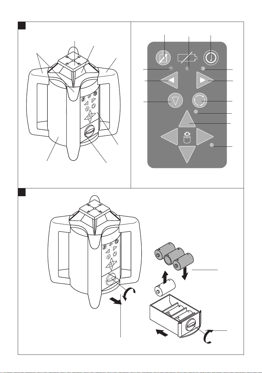
Component parts
PR 26 rotating laser
Laser beam (plane of rotation)
Rotating head
Control panel
Grip
Battery compartment
Base plate with
5
/8″ thread
Control panel
On/off button
Shock warning deactivation key
Rotation speed control key
Line function key
Direction keys (left/right)
Servo keys (set X/Y inclination/direction)
Auto leveling LED
Shock warning deactivation LED
Battery LED
X-inclination/direction LED
Y-inclination/direction LED
PRA 26 laser receiver
These numbers refer to the corresponding illustrations. The illustrations can be found on the fold-out cover
pages. Keep these pages open when studying the operating instructions.
In these operating instructions, the PR 26 rotating laser
is referred to as “the tool”.
Location of identification data on the tool
The type designation and serial number can be found
on the type plate on the tool. Make a note of this data in
your operating instructions and always refer to it when
making an enquiry to your Hilti representative or service department.
Type: PR 26
Serial no.:
Warning signs
Read the operating
instructions before use.
Symbols
General warning
Return waste
material for
recycling
Do not stare into the beam.
Laser class 3R in a accordance with EN 60825-1:2007
3R
DANGER
LASER RADIATION - AVOID DIRECT
EYE EXPOSURE
532nm < 4.5mW, max.
CLASS IIIa LASER PRODUCT
Page 6

14
en
2. Description
2.1 PR 26 rotating laser
The PR 26 is a rotating laser featuring a visible rotating
laser beam plus a point laser beam set at 90°to the rotating beam, which can be used to indicate the vertical,
horizontal or inclined planes.
2.2 Features
The tool allows a single person to level or align in any
plane quickly and with great accuracy.
Automatic leveling (within 10°): The tool levels itself
automatically after switching on. The laser beam is emitted only when the specified accuracy has been achieved.
LEDs indicate the tool's operating status.
Speed of rotation
The tool features 4 speeds of rotation. These are: stationary spot (zero rotation), slow rotation, mediumspeed rotation and fast rotation.
It is possible to switch between functions such as “Rotating laser” and “Line laser”. This can be done from the
PR 26 rotating laser or by way of the PRA 26 (combined
laser receiver and remote control unit).
Shock warning
The built-in shock warning function becomes active two
minutes after switching on: The tool switches to warning
mode (all LEDs blink, laser stops rotating) when brought
out of level as a result of vibration or an impact during
operation. All LEDs blink and the laser stops rotating.
Automatic cut-out
If movement of the mechanism is physically impeded
or the tool is set up outside its self-leveling range, the
laser remains switched off and all LEDs blink.
The tool can be set up on a tripod with a
5
/8″ thread or
stood directly on some other steady surface (free of
vibration).
-NOTE-
In some versions sold, the PRA 26 is not supplied as
standard with the PR 26. In this case, the functions can
be controlled directly from the PR 26 rotating laser itself
(excluding auto alignment/surveillance, which is possible only in conjunction with the PRA 26).
2.3 Description of functions
2.3.1 Horizontal plane (automatic leveling)
When switched on, the tool levels itself automatically by
way of the 2 built-in servo motors for the X- and Y-directions.
2.3.2 Inclined plane (any desired inclination)
Inclination can be set up in alignment with given marks
by pressing the X- and Y-keys on the PRA 26 or PR 26.
2.3.3 Automatic cut-out
During automatic leveling in one or both directions, the
servo system monitors compliance with the specified
accuracy.
The tool switches itself off in the following situations:
– Leveling is not accomplished (tool set up outside
its leveling range or the mechanism is physically
impeded).
– The tool is brought out of level (due to vibration or im-
pact).
After automatic cut-out, rotation of the laser beam stops
and all LEDs blink.
Items supplied
1 PR 26 rotating laser
1 PRA 26 laser receiver*
1 PR 26 operating instructions
1 PRA 26 operating instructions*
1 PR 25/PRA 25 operating instructions*
2 PRA 54 target plates
1 producer certificate
2 batteries (size AA cells)
1 PUA 80 battery charger
1 PUA 80 operating instructions
1 PRA 801 NiMH rechargeable battery
1 Region specific power cord for PUA 80
1 Hilti case
* Depending on the version purchased, this may not be
included in the items supplied.
Page 7

15
en
4. T echnical data for the PR 26
Range (diameter)
Range of remote control
Accuracy (at 24 °C/+75 °F)
Plumb beam
Laser product class
Speeds of rotation
Self-leveling range
Automatic cut-out
Operating status indicators
Power supply
Battery life at 20 °C [+68 °F]
Operating temperature
Storage temperature
Protection class
Tripod thread
Weight
Dimensions
Beam diameter 1/e
2
Right of technical changes reserved.
2 to 300 m [6 to 975 ft.] typically with the PRA 26
0 to 100 m [0 to 325 ft.] typically with the PRA 26
±1.0 mm @ 10 m [±
3
/32" @ 60 ft]
Continuously at right angles to plane of rotation
Class 3R, visible, 532 nm, < 4.5 mW
(IEC 825-1 / EN 60825-1:2007)
Class IIIa, visible, 532 nm, < 4,5 mW
[CFR 21; § 1040 (FDA)]
Zero, slow, medium, fast
(operating speed)
10°, LED indicator
When the laser is brought out of level (unless both
axes set to inclined mode):
– Rotation stops
– All LEDs blink
– Auto leveling LED
– Battery condition LED
– Shock warning LED
– X and Y inclination/direction LED
NiMH rechargeable battery (recommended) for
charging with PUA 80 or 3 size D alkaline batteries
NiMh batteries: 22 h typically
Alkaline batteries: 22 h typically
–20 °C to +45 °C [–4 °F to +110 °F]
–30 °C to +60 °C dry [–22 °F to +140 °F]
IP 56 (as per IEC 529)
5
/8″ x 18
Approx. 2.4 kg (5.3 lbs.) including NiMH battery
186 (L) x 186 (W) x 213 (H) mm
[7.3″ (L) x 7.3″ (W) x 8.4″ (H) inches]
< 2.8 mm at 10 m [
1
⁄8" @ 30ft] distance
3. Accessories
3.1 Accessories for the PR 26
Many tasks can be carried out much more efficiently
when the appropriate accessories for the PR 26 are used.
The following accessories are available:
– PRA 26 laser receiver
– PRA 54 target plate
– PRA 52 slope calculator
– PRA 70 and PRA 71 wall mounts
– PRA 76 slope adapter
– PRA 75 laser receiver holder
– PUA 80 charger and PRA 801 battery pack
– PA 375 batter board adapter , P A 377 tripod and facade
adapter
– PA 910, PA 911, PA 921 and PA 931/2, PUA 30 / 32
tripods
– PA 950/960 and PA 951/961 telescopic staffs
Page 8

● Use the tool only within its specified limits.
● Check that your PR 26 is being controlled by your
PRA 26 and that it is not reacting to commands from
any other PRA 26 in use on the construction site.
5.3.1 Electromagnetic compatibility
Although the tool complies with the strict requirements
of the relevant directives, Hilti cannot entirely rule out
the following possibilities:
● The tool may cause interference to other equipment,
e.g. aircraft navigational equipment.
● The tool may be subject to interference caused by
powerful radiation, possibly leading to incorrect operation. Check the readings for plausibility when measuring under these conditions or if you are unsure of
the results.
5.3.2 Laser classification for laser class IIIa / 3R
products
Depending on the version purchased, the tool conforms
to laser class IIIa / 3R based on the CFR 21 § 1040 (FDA)
and IEC825/EN60825-1:2007 standard.
Do not look into the laser beam and do not direct the
laser beam toward persons.
Laser warning plate based on IEC825/EN60825-1:2007
Laser warning plate for the US based on CFR 21 § 1040
(FDA)
This laser product complies with CFR 21 § 1040 (FDA)
as applicable.
-NOTE-
● Laser class IIIa / 3R tools should be operated only by
trained personnel.
● The area in which the tool is in use should be marked
with laser warning signs.
● The plane of the laser beam should be well above or
well below eye level.
● Precautionary measures must be taken to avoid inad-
vertent reflection of the laser beam from potentially
reflective surfaces.
● Precautionary measures must be taken to ensure that
persons do not look directly into the beam.
● The laser beam should not be projected into unsu-
pervised areas.
● When not in use, laser tools should be stored in a
place inaccessible to unauthorized persons.
16
en
5. Safety precautions
5.1 Basic information concerning safety
In addition to the information relevant to safety given in
each of the sections of these operating instructions, the
following points must be strictly observed at all times.
5.2 Intended use
The tool is designed to be used for determining, transferring or checking alignment in the horizontal plane,
inclined planes and right angles, e.g.
– Transferring datum and height marks
– Marking out right angles for walls
– Vertical alignment with a reference point
– Setting out inclines
Hilti offers various accessories that allow the tool to be
used with maximum efficiency.
● The tool and its accessories may present hazards when
used incorrectly by untrained personnel or when used
not as directed.
● To avoid the risk of injury, use only genuine Hilti acces-
sories and additional equipment.
● Tampering with or modification of the tool is not per-
missible.
● Observe the information printed in the operating instruc-
tions concerning operation, care and maintenance.
● Do not render safety devices ineffective and do not
remove information and warning notices.
● Keep laser tools out of reach of children.
● Have the tool repaired only at a Hilti service center.
Failure to follow the correct procedures when opening the tool may cause emission of laser radiation in
excess of class IIIa or, respectively, class 3R.
● Take the surrounding conditions into account. Do not
use the tool where there is a risk of fire or explosion.
* (Requested by FCC §15.21): Changes or modifications
not expressly approved by the party responsible for
compliance could void the user’s authority to operate
the equipment.
5.3 Proper organization of the workplace
● Secure the area in which you are working. When set-
ting up the tool, take care to avoid directing the beam
toward yourself or other people.
● Avoid unfavorable body positions when working on
ladders. Work from a stable stance and stay in balance at all times.
● Measurements taken through panes of glass or other
objects may be inaccurate.
● Ensure that the tool is set up on a steady surface (not
subject to vibration).
3R
DANGER
LASER RADIATION - AVOID DIRECT
EYE EXPOSURE
532nm < 4.5mW, max.
CLASS IIIa LASER PRODUCT
Page 9

17
en
5.4 General safety precautions
● Check the tool before use. If the tool is found to be
damaged, have it repaired at a Hilti service center.
● The accuracy of the tool must be checked after it has
been dropped or subjected to other mechanical stress.
● When the tool is brought into a warm environment
from very cold conditions, or vice versa, allow it to
become acclimatized before use.
● If mounting on an adapter, ensure that the tool is
screwed on securely.
● Keep the laser exit aperture clean to avoid measure-
ment errors.
● Although the tool is designed for the tough conditions
of jobsite use, as with other optical instruments (binoculars, spectacles, cameras) it should be treated with
care.
● Although the tool is designed to prevent entry of damp-
ness, it should be wiped dry each time before being
put away in its transport container.
● Check the tool before using it for important measur-
ing work.
● Check the accuracy of the tool regularly while in use.
5.4.1 Electrical
● Do not allow the batteries to fall into children's hands.
● Do not overheat or incinerate the batteries. They may
explode or release toxic substances.
● Do not attempt to recharge alkaline batteries.
● Do not solder the batteries into the tool.
● Do not discharge the batteries by short circuiting. This
may cause the batteries to overheat and swell up.
● Do not attempt to open the batteries and do not sub-
ject them to excessive mechanical stress.
6. Before use
-NOTE-
– The tool is powered by the PRA 801 battery pack.
Restricted operation:is possible with batteries, manufactured in accordance with the IEC 285 standard.
PR 801 battery pack
– The performance of the battery drops at low tempera-
tures.
– Store the battery at room temperature.
– Never store the battery where it is exposed to direct
sunlight, on a radiator or heater, or behind glass (win-
dows, motor vehicle windscreens, etc).
Batteries
– Do not use damaged batteries.
– Do not mix old and new batteries. Do not mix batter-
ies of different types or batteries from various manu-
facturers.
6.1 Switching on the tool
Press the on/off key.
-NOTE-
After switching on, the tool begins the automatic leveling process (max. 40 seconds). Once fully leveled, rotation of the tool head at the medium speed begins. Once
the operational temperature is reached (up to 1 minute)
the tool activates the laser beam in the rotational plane
and in the beam perpendicular to this.
Page 10

18
en
7. Operation
7.1 Switching the tool on
Press the on/off key.
7.2 Selecting the speed of rotation
The speed of rotation can be adjusted by pressing the
rotation speed control key (PR 26 or PRA 26). After
switching on, the PR 26 is set to rotate at medium speed,
as standard.
– Press the key once to set rotation to medium speed.
– Press the key again to set rotation to high speed.
– Press the key once more to return to medium speed.
– Press the key yet again to set rotation to low speed.
– A further press of the key stops rotation (spot).
– The next press of the key sets rotation to low speed.
– This procedure repeats itself.
7.2.1 Selecting the line function
After pressing the line function key, the PR 26 projects
a laser line. The line can be lengthened or shortened by
pressing the key again.
– Press the key once to project a short line.
– Press the key again to project a medium-length line.
– Press the key once more to project a long line.
– Press the key yet again to project an extra-long line.
– A further press of the key switches the tool back to the
long line.
– The next press of the key switches the tool back to the
medium-length line.
– This procedure repeats itself.
7.2.2 Moving the laser line and spot
The laser line or laser spot can be moved to the left or
right by pressing the direction keys (PR 26 or PRA 26).
Holding down the direction keys increases the speed of
movement and the laser line or spot then move continuously.
6.2 LED indicators
Auto leveling LED
The LED blinks rapidly.
The LED lights constantly.
Shock warning LED
All LEDs blink.
The shock warning LED lights red.
Battery voltage LED
The LED lights.
Inclination LED
The X and Y LEDs do not light.
The X LED does not light and the Y LED lights red.
The X LED lights red and the Y LED does not light.
The X LED lights red and the Y LED lights red.
The tool is leveling itself automatically.
The tool has leveled itself/is operating normally.
The tool has been bumped or brought out of level temporarily.
The shock warning LED lights red after deactivation of
the shock warning.
The battery pack is almost exhausted.
Operation in the horizontal plane.
The Y-direction has been aligned manually or by way
of auto alignment. X-direction is still under automatic
control.
The X-direction has been aligned manually or by way
of auto alignment. Y axis is still under automatic control.
The X- and Y-directions have been aligned manually or
by way of auto alignment. The shock warning system
is deactivated.
6.3 Inserting new batteries
1. Open the battery compartment by turning the lock-
ing button.
2. Insert the batteries in the battery compartment. Take
care to ensure correct polarity.
3. Close the battery compartment by turning the locking button.
Page 11

19
en
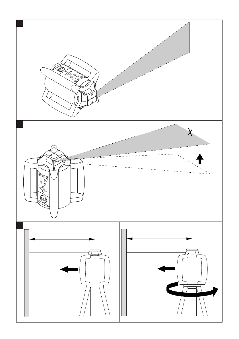
7.2.3 Working in the horizontal plane
– Mount the tool suitably, depending on the application,
e.g. on a tripod.
– Press the on/off key.
-NOTE-
The laser beam switches on and begins to rotate as soon
as the tool has leveled itself.
7.2.4 Working in the vertical plane
– Stand the tool on a level surface in a suitable position
for the application.*
– Press the on/off button.
-NOTE-
*In order to obtaine the specified accuracy , the tool
should be stood on an approximately level surface.
-NOTE-
The X LED does not light (the X-direction is brought into
vertical alignment automatically and monitored).
The Y LED lights red (the Y-direction can be aligned manually by way of the servo keys, the laser plane remains
perpendicular).
7.2.5 Automatic alignment
A basic prerequisite for auto alignment is that the PR 26
is set up accurately. The PR 26 must be set up so that
the correct axis (X or Y) is positioned in the direction in
which alignment is to be performed. This can only be
done in conjunction with the PRA 26.
Procedure:
– Position the PR 26 at the reference point and with the
correct axis in the direction in which alignment is to
be performed (the operating range for auto alignment
is a radius of 5-50 m).
– Position the PRA 26 laser receiver at the desired point.
– Check that no obstacles prevent communication between
the PR 26 and the PRA 26.
– Activate the auto alignment function by pressing the
X or Y key three times within one second. It is impor-
tant that the axes correspond correctly, i.e. when X (Y)
is to be aligned with the reference point, auto align-
ment of the X (Y) axis must be enabled by way of the
PRA 26.
– As long as the PR 26 is not in line laser mode, it then
switches automatically to medium rotation speed and
begins the search process. The auto align function is
indicated in the display by the axis currently being
aligned and by blinking arrows. An audible signal is
emitted continuously during the search process.
– The direction of the search process can be changed
by pressing the direction arrows.
– The beam moves to the zero point (reference plane)
as soon as the laser beam strikes the detection area
on the PRA 26 laser receiver.
– After reaching this point (finding the reference plane),a
signal sounds briefly indicating that the process is
complete. Only the axis that has been aligned is then
shown in the display.
If the process cannot be completed within a certain period
of time, an error is indicated in the display.
-NOTE- If an error is displayed
Please check that the PRA 26 is positioned within the
inclination range (10°) and that no obstacles are located
between the rotating laser and the laser receiver.
7.2.6 Manual alignment with the PR 26
A basic prerequisite for manual alignment is that the
PR 26 is set up accurately. The PR 26 must be set up so
that the correct axis (X or Y) is positioned in the direction in which alignment is to be performed.
Procedure:
– Position the PR 26 at the reference point and with the
correct axis in the direction in which alignment is to
be performed (the operating range for manual alignment is a radius of 5–50 m).
Setting the X-direction manually
– Press one of the X-servo keys twice within 2 seconds.
– The X-servo keys can then be used to perform man-
ual alignment.
-NOTE-
The X LED lights red.
Setting the Y-direction manually
– Press one of the Y-servo keys twice within 2 seconds.
– The Y -servo keys can then be used to perform man-
ual alignment.
-NOTE-
The Y LED lights red.
7.2.7 Manual alignment using the PRA 26
A basic prerequisite for manual alignment is that the
PR 26 is set up accurately. The PR 26 must be set up so
that the correct axis (X or Y) is positioned in the direction in which alignment is to be performed.
Procedure:
– Position the PR 26 at the reference point and with the
correct axis in the direction in which alignment is to
be performed (the operating range for manual alignment is a radius of 5–50 m).
– Check that no obstacles prevent communication
between the PR 26 and the PRA 26.
– Activate the manual alignment function by pressing the
X or Y key twice within 1 second. It is important that
the axes correspond correctly, i.e. when X (Y) is to be
aligned with the reference point, auto alignment of the
X (Y) axis must be enabled by way of the PRA 26.
– The laser beam can be moved to the desired position
by pressing the direction keys. Holding down the direction keys increases the speed of movement and the
laser line or spot then move continuously.
– The manual alignment function is indicated in the dis-
play by the axis currently being aligned and by stationary (constantly lit) arrows. An audible signal is also
emitted continuously during the search process.
Page 12

20
en
– The system switches to normal operation when no key
is pressed within 5 seconds. Only the axis that has
been aligned is then indicated in the display.
7.2.8 Surveillance
The surveillance function checks to ensure that no displacement of the aligned plane has occurred (e.g. due
to vibration). If displacement has occurred, the laser
plane is realigned to the zero point (as long as it is still
within the detection area). An additional laser receiver
is required for working with the surveillance function. A
PRA 26 may be used to detect the laser beam.
As surveillance begins by way of the auto alignment
function, the PR 26 must be set up accurately. The
PR 26 must be set up so that the correct axis (X or Y)
is positioned in the direction in which alignment is to be
performed.
Procedure:
– Position the PR 26 at the reference point and with the
correct axis in the direction in which alignment is to
be performed (the operating range for auto alignment
is a radius of 5–50 m).
– Position the PRA 26 laser receiver at the desired point.
– Check that no obstacles prevent communication between
the PR 26 and the PRA 26.
– Activation of this function requires the PRA 26 to be
switched off. While pressing and holding the X or Y
key (the key for the axis you wish to align), switch on
the laser receiver by pressing the on/off key.
– The system is then in surveillance mode. The moni-
toring function is indicated in the display – the LEDs
for the axis to be aligned and the arrows blink alter-
nately.
– The auto alignment process then begins as previously
described.
– The auto alignment process stops as soon as the zero
point has been found. In contrast to full auto align-
ment, no audible signal is emitted at the end of the
process.
– A check is carried out at regular intervals to ensure
that laser the plane has not been displaced. If it is found
to have been displaced, the laser plane is again brought
into alignment with the zero point (as long as the laser
beam is still within the detection area and line of sight
between the rotating laser and the laser receiver has
not been interrupted for a long period). In the event of
prolonged interruption of the line of sight between the
two devices, an error is indicated after 30 seconds.
-NOTE- If an error is displayed
Please check that the PRA 26 is positioned within the
self levelling range (10°) and that no obstacles are located
between the rotating laser and the laser receiver.
After successfully setting to the zero point, take care to
ensure that the line of sight between the two devices is
not interrupted.
7.2.9 Pairing
It is possible to configure the PR 26 and the PRA 26 as
a pair. When the two devices are paired, the rotating laser
and the detector are assigned to each other. The rotating laser then receives commands only from its “own”
detector/remote control unit. The devices can be paired
by pressing and holding down the on/off keys on both
devices simultaneously.
-NOTE-
The PR 26 and PRA 26 are not paired when supplied.
Each unpaired rotating laser receives commands from
any unpaired laser receiver.
Pairing procedure:
– The devices can be paired by pressing and holding
down the on/off keys on the PR 26 and PRA 26 simultaneously, as previously described, for more than 3
seconds. Successful pairing is confirmed by an audible signal emitted by the PRA 26 and by the LEDs on
the PR 26 blinking.
Cancelling pairing:
– Pairing can be cancelled by pressing and holding down
the on/off keys for more than 3 seconds. Cancellation
of pairing can only be successful when the on/off keys
on the PR 26 and PRA 26 are not pressed simultaneously. Successful cancellation of pairing is confirmed
by the PRA 26 by the emission of an audible signal
and by the symbol “!” displayed. The PR 26 confirms
cancellation of pairing by causing all LEDs to blink.
7.2.10 Working with the target plate
The target plate improves visibility of the laser beam.
The target plate for the PR 26 is particularly useful in
bright conditions or wherever better visibility of the laser
beam is required.
7.2.11 Working with the laser receiver
Please refer to the PRA 26 operating instructions for
information about the laser receiver.
7.2.12 Continuing work in manual mode after a
restart
In order to continue working in manual mode after a
restart, it is necessary to press one of the “servo” keys
on the PR 26 within 3 seconds.
7.2.13 Returning to standard mode
To return to standard mode, switch the tool off and then
restart it.
Page 13

8. Hilti calibration service
We recommend that the tool is checked by the Hilti
Calibration Service at regular intervals in order to verify
its reliability in accordance with standards and legal
requirements.
Use can be made of the Hilti Calibration Service at any
time, but checking at least once a year is recommended.
The Calibration Service provides confirmation that the
tool is in conformance, on the day it is tested, with the
specifications given in the operating instructions.
The tool will be re-adjusted if deviations from the manufacturer's specification are found. After checking and
adjustment, a calibration sticker applied to the tool and
a calibration certificate provide written verification that
the tool operates in accordance with the manufacturer's
specification.
Calibration certificates are always required by companies certified according to ISO 900x.
Your local Hilti Center or representative will be pleased
to provide further information.
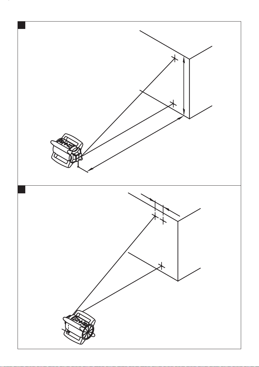
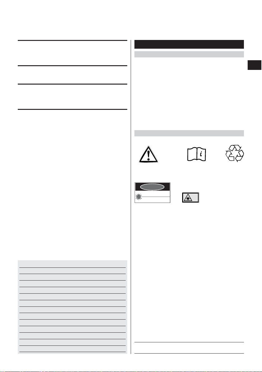
8.1 Accuracy
The accuracy of the tool in the X- or Y-directions can be
checked as described below.
8.1.1 Checking procedure
1. Set up the tool in the horizontal plane at a distance of
about 20 m (60 ft) from a wall (can also be carried
out with the tool set up on a tripod).
2. Make a mark on the wall with the aid of the laser receiver
(select medium speed of rotation).
3. Pivot the tool through 180° about its own axis (check
the same laser axis).
4. With the aid of the laser receiver, make a second mark
on the wall.
If the check has been carried out carefully, the distance
between the marks A and B should be less than 6 mm
(
7
/32 inch; at 20 m from the wall).
⇒ In the event of a deviation in excess of this, please
return the tool to a Hilti Service Center.
9. Care and maintenance
9.1 Cleaning and drying
● Blow dust off the lenses.
● Do not touch the glass with your fingers.
● Use only a clean, soft cloth for cleaning. If necessary,
slightly moisten the cloth with pure alcohol or a little
water.
-NOTE-
● Do not use any other liquids as these may damage
the plastic parts.
● Observe the temperature limits when storing your
equipment. This is particularly important in winter or
summer, especially if the equipment is kept inside a
vehicle (storage temperatures: –30 °C to +60 °C/
–22 °F to +140 °F).
9.2 Storage
Remove the tool from its case if it has become wet. Clean
and dry the tool, its carrying case and accessories
(at max. temperature of 40 °C/108 °F). Re-pack the equipment only when it is completely dry.
Check the accuracy of the equipment before it is used
after a long period of storage or transportation.
Remove the batteries if the tool is to be stored for a long
period.
9.3 Transportation
Use either the original Hilti case or packaging of equivalent quality for transporting or shipping your equipment.
-CAUTION-
Always remove the battery pack or batteries before shipping the tool.
21
en
Page 14

22
en
11. Manufacturer's warranty – tools
Hilti warrants that the tool supplied is free of defects
in material and workmanship. This warranty is valid
so long as the tool is operated and handled correctly,
cleaned and serviced properly and in accordance with
the Hilti Operating Instructions, and the technical
system is maintained. This means that only original
Hilti consumables, components and spare parts may
be used in the tool.
This warranty provides the free-of-charge repair or
replacement of defective parts only over the entire lifespan of the tool. Parts requiring repair or replacement
as a result of normal wear and tear are not covered by
this warranty.
Additional claims are excluded, unless stringent
national rules prohibit such exclusion. In particular,
Hilti is not obligated for direct, indirect, incidental
or consequential damages, losses or expenses in
connection with, or by reason of, the use of, or inability to use the tool for any purpose. Implied warranties of merchantability or fitness for a particular
purpose are specifically excluded.
For repair or replacement, send tool or related parts
immediately upon discovery of the defect to the address
of the local Hilti marketing organization provided.
This constitutes Hilti's entire obligation with regard to
warranty and supersedes all prior or contemporaneous
comments and oral or written agreements concerning
warranties.
10. Disposal
-CAUTION-
Improper disposal of the equipment may have serious consequences:
● The burning of plastic components generates toxic fumes which may present a health hazard.
● Batteries may explode if damaged or exposed to very high temperatures and thus cause poisoning, burns, acid
burns or environmental pollution.
● Careless disposal may permit unauthorized and improper use of the equipment, possibly leading to serious
personal injury, injury to third parties and pollution of the environment.
Most of the materials from which Hilti tools or appliances are manufactured can be recycled. The materials must
be properly separated before they can be recycled. In many countries, Hilti has already made arrangements for
taking back old tools and appliances for recycling. Ask Hilti Customer Service or your Hilti Representative for further information.
Only for EU countries
Disposal of electric tools together with household waste is not permissible!
In observance of European Directive 2002/96/EC on waste electrical and electronic equipment and
its implementation in accordance with national law, electric tools that have reached the end of their life
must be collected separately and returned to an environmentally compatible recycling facility.
Dispose of batteries in accordance with national regulations
Page 15

23
en
This device complies with Part 15 of the FCC Rules and
RSS-210 of IC. Operation is subject to the following two
conditions:
(1) this device may not cause harmful interference, and
(2) this device must accept any interference received,
including interference that may cause undesired
operation.
Information plates on the product:
-CAUTION-
This equipment has been tested and found to comply
with the limits for a class B digital device, pursuant to
part 15 of the FCC rules. These limits are designed to
provide reasonable protection against harmful interference
in a residential installation. This equipment generates,
uses, and can radiate radio frequency energy and, if not
installed and used in accordance with the instructions,
may cause harmful interference to radio communications.
However, there is no guarantee that interference will not
occur in a particular installation.
If this equipment does cause harmful interference to
radio or television reception, which can be determined
by turning the equipment on and off, the user is encouraged to try to correct the interference by one or more of
the following measures:
● Re-orient or re-locate the receiving antenna.
● Increase the distance between the equipment and
receiver.
● Connect the equipment to an outlet on a circuit dif-
ferent from that to which the receiver is connected.
● Consult the dealer or an experienced TV/radio tech-
nician for assistance.
Changes or modifications not expressly approved by
Hilti could restrict the user's right to operate the equipment.
12. FCC statement (applicable in US) / IC statement (applicable in Canada)
13. EC conformity
In conformance with CE
We declare, on our own responsibility, that this product
complies with the following directives and standards:
EN 300 440-2, EN 301 489-3 V1.4.1, EN 60950-1:2006 /
IEC 60950-1:2006 (DIN), EN 61000-6-2, EN 61000-6-3.
Designation: Rotating laser
Type: PR 26
Year of design: 2008
364390
PR 26
Power:
3.6V=nom./ 1,6 A
CLASS IIIa LASER PRODUCT
532nm < 4.5mW, max.
LASER RADIATION - AVOID DIRECT
EYE EXPOSURE
3R
EN 60825-1:2007
01
Hilti=trademark of Hilti Corp., Schaan, LI Made in Germany
DANGER
Hilti Corporation
Tassilo Deinzer Reinhard Waibel
Head Head of Development
Measuring Systems BU Measuring Systems BU
02/2008 02/2008
Page 16

Hilti Corporation
LI-9494 Schaan
Tel.:+423 /234 2111
Fax: +423/2342965
www.hilti.com
Hilti = registered trademark of Hilti Corp., Schaan W3505 0308 10-Pos. 1 1 Printed in Liechtenstein © 2008
Right of technical and programme changes reserved S. E. & O.
388027 / A
*388027*
388027
 Loading...