

Hellwig 7555 User Manual
559-734-7451 800-367-5480 FAX 559-734-7460
INSTALLATION INSTRUCTIONS
1988-98 C/K 1500-2500-3500 Single Wheel
Rear Stabilizer Bar
Thank you for purchasing a quality Hellwig Product.
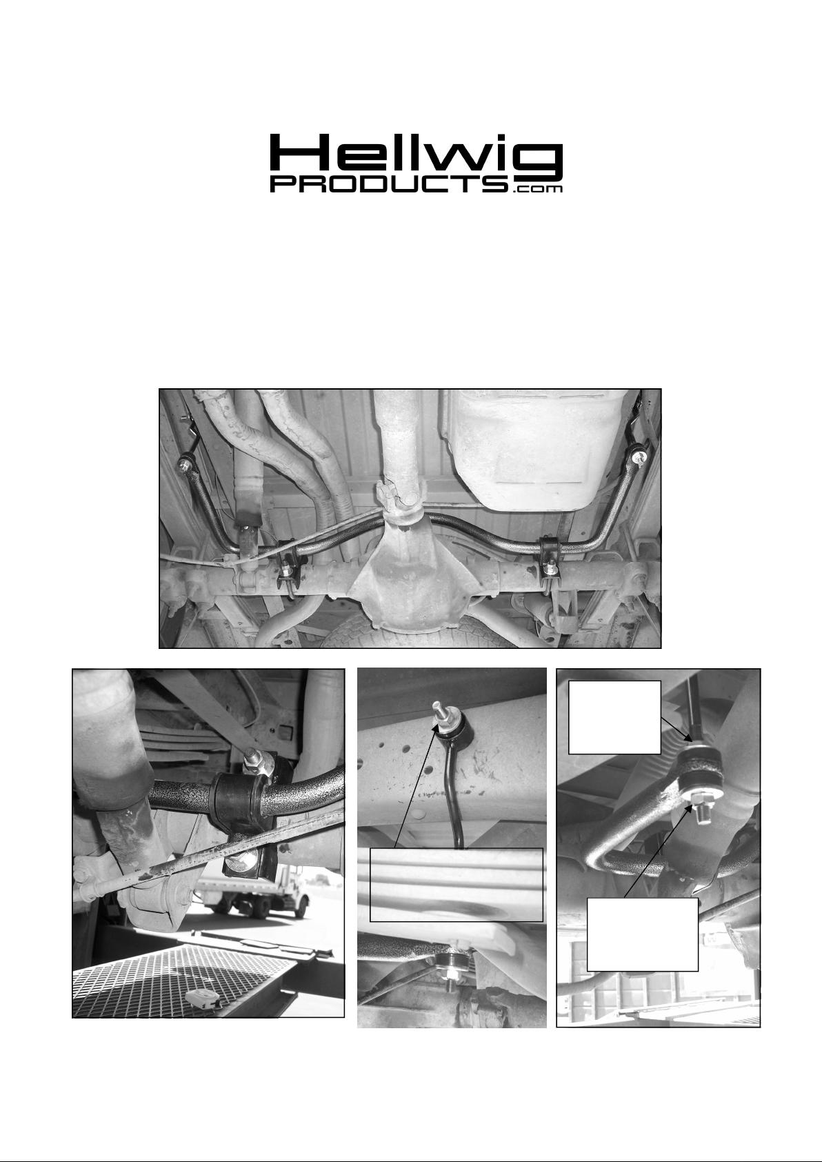
Install jamnut
and hexnut on
top of bushing
assembly
Align endlinks for best fit
and drill 17/32 (.531”) hole
in frame to attach end link to
frame with 1/2” bolt.
R-7555 5/30/2008
Install lock nut on
bottom of bushing
assembly.

559-734-7451 800-367-5480 FAX 559-734-7460
TORQUE TABLE
Bolt Size 3/8”— 25 ft lbs * Bolt Size 7/16”— 35 ft lbs* Bolt Size 1/2”—55 ft lbs
SAFETY: BEFORE BEGINNING INSTALLATION BE SURE TO SET THE PARKINGBRAKE ANDCHOCK THE
WHEELS.
NOTE: TO EASE INSTALLATIONAND PROPERLY ADJUST THE BAR, THE WEIGHT OF THE VEHICLE MUST
BE ON THE SUSPENSION AS IF DRIVING DOWN THE ROAD.DO NOT RAISETHE VEHICLEBY THE FRAME.
1. Lubricate the D-bushings and place them onto the straight areas of the bar on each side of the center hump
as shown in the photos.
2. Position sway bar on axle as shown in photos and locate the position on the axle tubes to mount the ubolts. Be sure to put the U-Bolts Under Any Brake Lines, Wires or Hoses on the Axle to Avoid Any
Possible Damage.
3. Place saddle brackets onto the U-Bolts on the axle tubes. Place the U-Plates over the D shaped bushings on
the bar and attach the sway bar to the U-Bolts and saddle brackets with the flat washers and locknuts provided. LEAVE LOOSE AT THIS TIME to allow for adjustment later.
4. Assemble end links by installing the hourglass bushing and then the spacer into the loop of the end link.
Lubricate bushing and spacer before assembly.
5. Assemble bushings, washers and nuts on end link as shown in photos. The lock nut is installed on the bottom of the end link bushing assembly. Adjust jam nut and hex nut on upper portion of end link to raise or
lower assembly to align arms of sway bar to be as parallel with ground as possible.
6. Tighten lock nut on bottom of end link until bushings begin to bulge slightly. Tighten jam nut against upper hex nut to lock adjustment.
7. Align end links for best fit as shown in photos so that end links are perpendicular to the sway bar and the
arms of the sway bar are parallel with the ground. .When satisfied with the location and alignment of the
end links, mark location of holes for the end links on frame rail.
8. Drill a 17/32 (.531) hole in the frame at marked locations. BEFORE DRILLING ANY HOLES IN THE
RAIL—RELOCATE AND/OR PROTECT FUEL TANK AND ANY WIRES, FUEL, OR BRAKE
LINES THAT MAY INTERFERE WITH THE DRILL BIT OR SWAY BAR INSTALLATION.
9. Attach end links to hole in frame rail using the 1/2” X 2-1/2” bolt, washers and 1/2” locknut. Install bolt
through end link with a flat washer mounted to the inside of the frame rail and the outside of the bushing.
Tighten to 60 ft-lb.
10. Adjust sway bar on axle so that there is at least 1/2” clearance between the bar and the axle. Ensure adequate clearance between the sway bar and all shock absorbers, brake lines, hoses, cables and electrical connections. When all clearances are confirmed, tighten U-bolts to 30-35 ft-lb. Double nut and tighten.
11. Bounce vehicle and check for clearance on all undercarriage components. Recheck installation, look for
clearance on gas lines, exhaust pipes, brake lines, wiring, etc.
12. Drive vehicle for a few miles, then recheck for position and tightness, readjust and retorque as needed.
Then recheck periodically thereafter.
ATTENTION INSTALLER: PLEASE MAKE SURE CUSTOMER RECEIVES THIS INSTRUCTION SHEET,
ALL IMPORTANT NOTE CARDS, WARNING CARDS AND THE WARRANTY
FORM
R-7555 5/30/2008
 Loading...