

559-734-7451 800-367-5480 FAX 559-734-7460
INSTALLATION INSTRUCTIONS
REAR STABILIZER BAR
03-06 Dodge Sprinter
1 2
3
4
7239 ( R-7239 ) 06/24/07

559-734-7451 800-367-5480 FAX 559-734-7460
TORQUE TABLE
BOLT SIZE: 3/8” = 20-30 ft. lbs. – 7/16” = 35-45 ft. lbs. – ½” = 50-70 ft. lbs. – 9/16” = 70-90 ft. lbs
SAFETY: BEFORE STARTING YOUR INSTALLATION, BE SURE TO SET PARKING BRAKE AND CHOCK TIRES.
NOTE: TO EASE INSTALLATION AND TO PROPERLY ADJUST THE BAR, THE WEIGHT OF THE VEHICLE MUST BE
ON THE SUSPENSION, AS IF DRIVING DOWN THE ROAD. DO NOT RAISE VEHICLE BY FRAME.
NOTE: THIS KIT INCLUDES LOCK NUTS WHICH REQUIRE TIGHTENINGWITH A WRENCH AFTER BEING STARTED
BY HAND.
NOTE: THIS ANTI-SWAY BAR MOUNTS ON THE REAR OF THE AXLE WITH THE ARMS POINTINGTOWARDSTHE
REAR OF THE VEHICLE.
1. Remove factory installed sway bar.
2. Install the U-bolts on the rear axle with the legs towards the rear of the vehicle. Be sure that the brake lines
are outside of the U-bolt legs and will not be damaged when tightening the U-bolts.
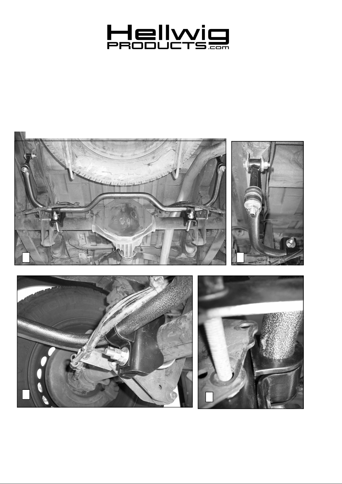
3. Install the D-shaped poly bushings on the sway bar as close as possible to match the U-bolts that are
mounted on the axle. SEE PHOTOS ONE (1) AND THREE (3).
4. Place the saddle brackets on the axle and insert the legs of the u-bolts through the holes in the saddles.
Raise the sway bar up to the axle. Position the U-plates over the D-bushings. Using the 1/2” nuts and washers provided tighten enough to support the sway bar on the axle. Leave loose at this time to allow for ad-
justment later.
5. Insert bushing halves first and then the sleeve into loop of the end link assembly. Lubricate the bushing
and sleeve to ease assembly.
6. Attach the end links to the factory brackets using the 7/16-2-1/4” bolts washers and locknuts. Tighten to 30
ft-lb.
7. Assemble end links as shown in PHOTO TWO placing the spacer on first and then the washers and bushings. Raise the sway bar arms up to the end link assemblies and attach the arms of the sway bar to the end
links. Tighten the nuts until the bushings start to bulge slightly. Over tightening will cause damage to
the bushings.
8. With the sway bar centered on the axle the sway bar will be positioned as shown in photos ONE, THREE
AND FOUR. Tighten the U-bolts to 75 ft-lb and double nut.
9. Check your installation check for clearance on undercarriage components; wires, exhaust, brake and fuel
lines.
10. After one week of driving recheck your installation readjust if necessary. Recheck your installation on a
monthly regular basis thereafter.
ATTENTION INSTALLER: BE SURE THAT THE CUSTOMER RECEIVES THIS INSTRUCTION SHEET,
ALL IMORTANT NOTE CARDS AND THE WARRANTY FORM
7239 ( R-7239 ) 06/24/07
 Loading...