

Hellwig 7218 User Manual
559-734-7451 800-367-5480 FAX 559-734-7460
INSTALLATION INSTRUCTIONS
Front Stabilizer Bar
Workhorse W20,W22 Models
Thank you for purchasing a quality Hellwig Product.
PLEASE READ THIS INSTRUCTION SHEET COMPLETELY BEFORE STARTING YOUR INSTALLATION
TORQUE TABLE
BOLT SIZE: 3/8” = 20-30 ft. lbs. – 7/16” = 35-45 ft. lbs. – ½” = 50-70 ft. lbs. – 9/16” = 70-90 ft. lbs.
SAFETY: BEFORE STARTING YOUR INSTALLATION, BE SURE TO SET PARKING BRAKE AND CHOCK TIRES.
NOTE: TO EASE INSTALLATION AND TO PROPERLY ADJUST BAR, THE WEIGHT OF THE VEHICLE MUST BE
ON THE SUSPENSION, AS IF DRIVING DOWN THE ROAD. DO NOT RAISE VEHICLE BY FRAME.
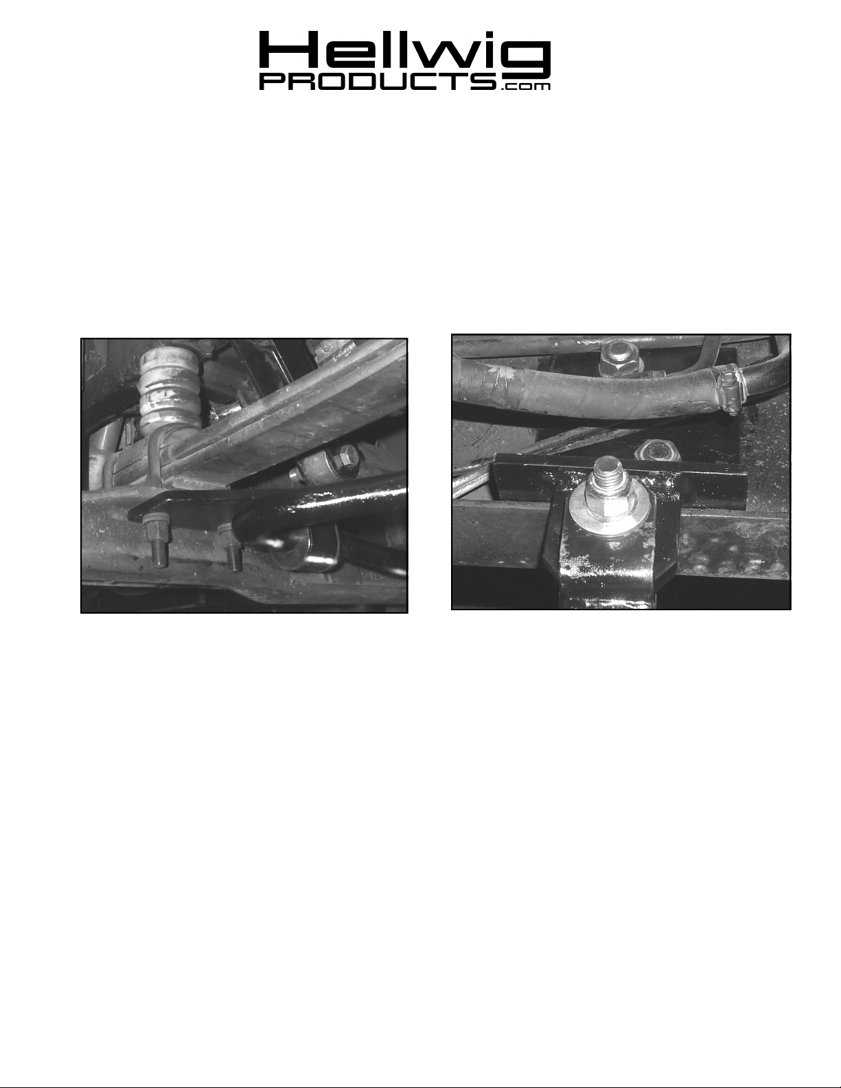
1. Remove the two most forward U-bolts on the front axle.
2. Install the Hellwig axle plate on the bottom of the axle with U-plate mounting holes facing inboard on the vehicle. Secure the
axle plates with O.E. hardware and torque to factory specifications. (See picture 1)
3. Locate frame brackets using the holes in the side of the frame rail forward of the axle. The holes on the driver side are used
for the steering box mount and on the passenger side the two holes are open. Remove two steering box bolts to mount drivers
side frame bracket. The frame bracket mounts to the inside of frame rail with the bushing tab inboar d of the rail flange. (See
picture 2) Use caution when installing frame bracket on driver’s side. Install bracket under or behind all electrical and hard
lines. Secure frame bracket with hardware provided and torque to factory spec’s.
4. Repeat process on passenger side. Fra me holes are open on passenger side.
5. Install endlinks to frame brackets. Leave loose at this time.
7218 (R-7218) 07/08/03
22 1
.
ATTENTION INSTALLER: PLEASE MAKE SURE CUSTOMER RECEIVES THIS INSTRUCTION SHEET,
3
559-734-7451 800-367-5480 FAX 559-734-7460
4
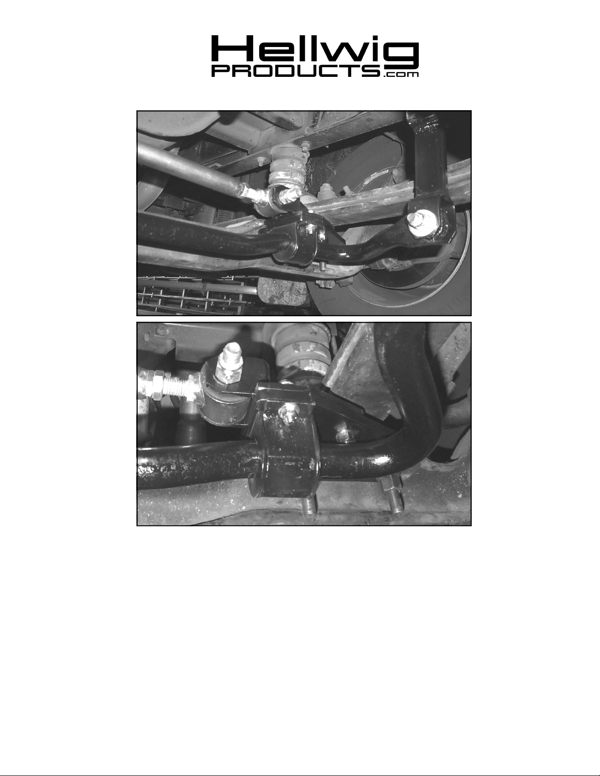
6. With frame bracket & axle plates installed, attach the anti-swaybar on the bottom of the axle plates using the D-bushing &
U-plates. (See picture 3). Orient the hump of the swaybar down & the arms forward towards the front of the coach. Leave
bolts loose enough for adjustment later. Connect the swaybar to the endlink using hardware provided. Center the swaybar
in the U-plate so that the bar lines up with the endlinks. The endlinks should be straight in line with the swaybar at this time
7. Track bar adapter plate mounts on top of drivers side axle plate with the same 3/8 hardware that secures the u-plate to axle
plate and 1 ½” cap screw. (See picture 4).
8. When satisfied with fit and clearance of all components tighten all hardware to recommended specifications.
ALL IMPORTANT NOTE CARDS, WARNING CARDS AND THE WARRANTY
FORM.
7218 (R-7218)
 Loading...