

559-734-7451 800-367-5480 FAX 559-734-7460
INSTALLATION INSTRUCTIONS
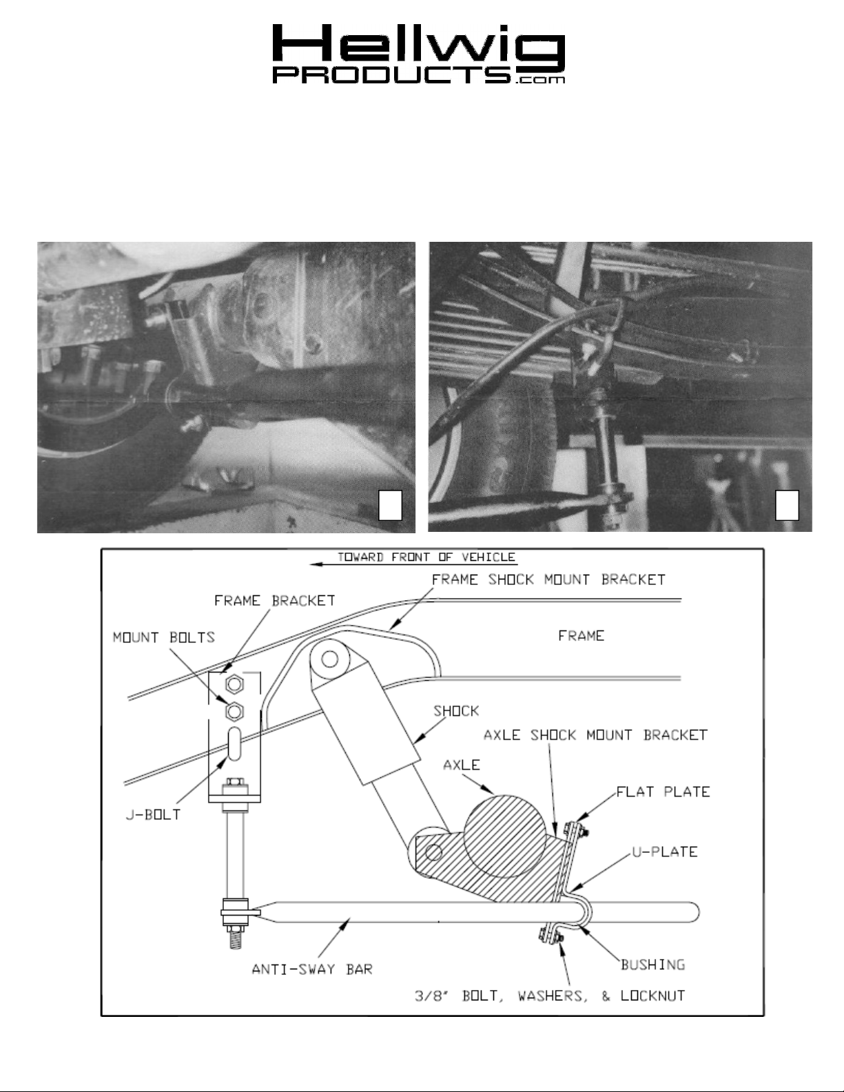
REAR STABILIZER BAR
Thank you for purchasing a quality Hellwig Product.
PLEASE READ THIS INSTRUCTION SHEET COMPLETELY BEFORE STARTING YOUR INSTALLATION
1
2
( R-131 ) 11/29/2012

559-734-7451 800-367-5480 FAX 559-734-7460
SAFETY: BEFORE STARTING YOUR INSTALLATION, BE SURE TO SET PARKING BRAKE AND CHOCK TIRES.
NOTE: TO EASE INSTALLATION AND TO PROPERLY ADJUST THE BAR, THE WEIGHT OF THE VEHICLE MUST BE
ON THE SUSPENSION, AS IF DRIVING DOWN THE ROAD. DO NOT RAISE VEHICLE BY THE FRAME.
NOTE: THIS UNIT IS DESIGNED TO MOUNT TO THE BACK OF THE SHOCK MOUNTS ON THE REAR OF THE AXLE
WITH THE ARMS OF THE BAR TOWARD THE FRONT OF THE VEHICLE.
NOTE: THIS KIT INCLUDES LOCK NUTS WHICH REQUIRES TIGHTENING WITH A WRENCH AFTER BEING
STARTED BY HAND.
IMPORTANT: IT WILL BE NECESSARY TO REMOVE THE LOWER SHOCK BOLTS FROM THE AXLE MOUNTS AND
REVERSE THEIR DIRECTION TO THE THREADED ENDS OF THE SHOCK BOLTS DO NOT INTERFERE OR CONTACT
BOLT SIZE: 3/8” = 20-30 ft. lbs. – 7/16” = 35-45 ft. lbs. – 1/2” = 50-70 ft. lbs. – 9/16” = 70-90 ft. lbs.-5/8”=120 ft. lbs.
THE SWAY BAR.
TORQUE TABLE
1. Place the flat plates inside the open area on the back of the shock mounts so the holes in the flat plates
are above and below the flat surface on the back of the shock mounts. See Photos.
2. Lubricate the insides and then place the D-shaped poly bushings on each side of the center hump to
align with the shock mounts and flat plates.
3. Place the U-plates over the bushings on the bar so the offset lets the sway bar so the offset lets the sway
bar mount down toward the bottom of the flat plates and shock mounts. Attach the U-plates to the flat
plates with the 3/8” mounting hardware provided. LEAVE LOOSE at this time to allow for adjustment.
Move any brake lines or hoses on the axle to avoid any contact wear with the flat plates or the U-plates.
4. As per the Photos and Diagrams, assemble the end links and angle brackets to the end of the sway bar.
Tighten the end link locknuts just until the bushings bulge slightly. DO NOT OVERTIGHTEN or damage to the end link bushings will result.
5. Rotate the bar upward so the frame angle brackets fit up against the outside of the frame rails. Some
chassis have two holes predrilled into the frame and will align with the upper two holes in the angle
bracket. Attach these two holes wit the remaining 3/8” mounting hardware provided. LEAVE LOOSE
to allow for adjustments.
6. If your vehicle has only one hole in the frame rail, attach the angle bracket to the hole and use the J-bolt
provided to hook onto the frame and mount through the lower hole in the angle bracket. Be sure there
are two mounting points for each of the angle brackets. It may be necessary to use the exhaust hanger
bolts on the passenger side on some vehicles.
7. Center the bar under the vehicle and adjust the end links to be as straight between the ends of the sway
bar and the angle brackets as possible. Being sure not to pinch an wires, lines or hoses inside the frame
or on the axle, torque all of the mounting hardware to the specified rate.
8. Bounce the vehicle checking for clearance on all undercarriage components. Adjust the bar as needed.
Recheck your installation after driving and recheck periodically on a regular basis.
ATTENTION INSTALLER: BE SURE THE CUSTOMER RECEIVES THIS INSTRUCTION
SHEET, ALL IMPORTANT NOTE CARDS, WARNING CARDS AND THE WARRANTY FORM.
( R-131 ) 11/29/2012
 Loading...