

559-734-7451 800-367-5480 FAX 559-734-7460
INSTALLATION INSTRUCTIONS
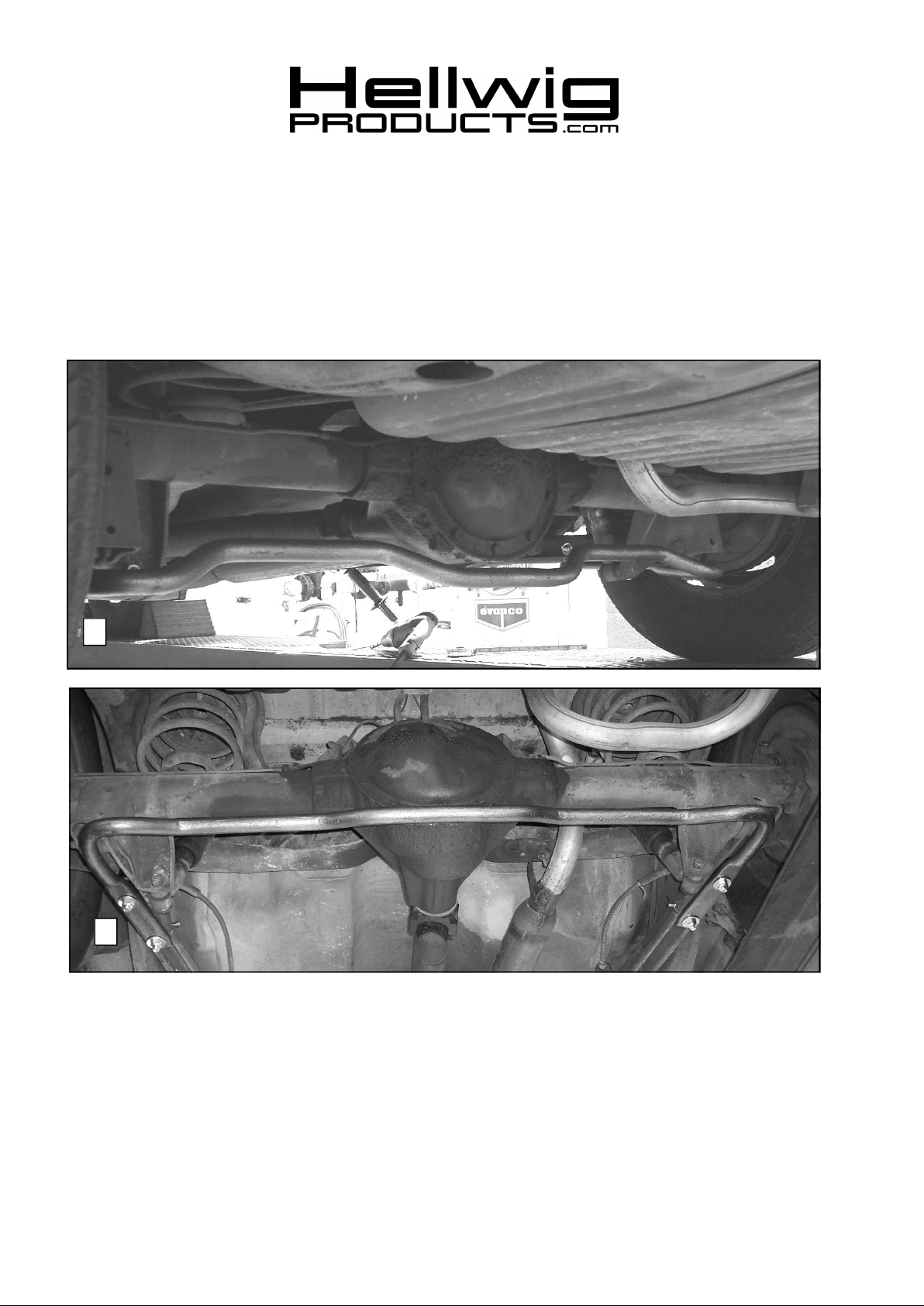
REAR STABILIZER BAR
73-77 GMA-Body RSB
77-96 Impala, Caprice RSB
Thank you for purchasing a quality Hellwig Product.
PLEASE READ THISINSTRUCTIONSHEETCOMPLETELY BEFORE STARTING YOUR INSTALLATION
1
2
TORQUE TABLE
BOLT SIZE: 3/8” = 20-30 ft. lbs. – 7/16” = 35-45 ft. lbs. – ½” = 50-70 ft. lbs. – 9/16” = 70-90 ft. lbs.-5/8”=120 ft. lbs
SAFETY: BEFORE STARTING YOUR INSTALLATION, BE SURE TO SET PARKING BRAKE AND CHOCK
TIRES.
NOTE: THIS UNIT IS DESIGNED TO REPLACE THE FACTORY INSTALLED REAR ANTI-SWAY BAR. OR AS
AN ADDITION IF THE VEHICLE WAS NOT EQUIPPED WITH A FACTORY REAR SWAY BAR.
NOTE: THIS KIT INCLUDES LOCKNUTS WHICH REQUIRE TIGHTENING WITH A WRENCH AFTER
BEING STARTED BY HAND.
5803 ( R-5803 ) 02/15/07
559-734-7451 800-367-5480 FAX 559-734-7460
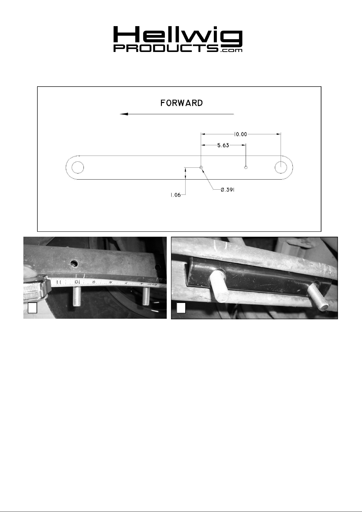
ControlArm Drilling Diagram
3 4
1. If equipped, remove factory sway bar and attach new sway bar using factory hardware.
2. If not equipped with factory rear sway bar, disconnect rear shock absorbers and lay out
holes per drilling diagram above. Locate the first hole 10 inches from the center of the
rear control arm bushing and 1.06 inches above the bottom of the control arm. See photo
(3) Locate the second hole 5.63 inches rearward from the first hole. Check location of
holes using slotted holes in control arm insert as a guide. When satisfied with the location of the holes, drill qty 2 .391” diameter holes through each wall of the lower control
arm. Make sure the holes are square to the control arm.
3. Place 1/2” X 1-1/2” bolts in control arm insert and place insert inside lower control arm
as shown in photo (4). Align slotted holes in insert with holes drilled in step 2.
5803 ( R-5803 ) 02/15/07

559-734-7451 800-367-5480 FAX 559-734-7460
5
4. Insert 3/8 x 2-1/4” bolts into holes in control arm and fasten assembly with washers and
locknuts as shown in photo (5).
5. Orient sway bar as shown in photo (1) and attach using the 1/2” bolts washers and locknuts.
6. Tighten 3/8” bolts to 20-25 ft-lb. Tighten 1/2” bolts to 40-50 ft-lb.
7. Bounce vehicle a couple of times and check installation for clearance to fuel and brake
lines and other components. After one week of driving recheck your installation and
fastener torque. Recheck on a regular basis thereafter.
ATTENTION INSTALLER: BE SURE THAT THE CUSTOMER RECEIVES THIS INSTRUC
TION SHEET, ALL IMORTANT NOTE CARDS AND THE
WARRANTY FORM
5803 ( R-5803 ) 02/15/07
 Loading...