

Page 1
559-734-7451 800-367-5480 FAX 559-734-7460
INSTALLATION INSTRUCTIONS
Thank you for purchasing a quality HellwigProduct.
PLEASE READ THISINSTRUCTION SHEET COMPLETELY BEFORE STARTING YOUR INSTALLATION
TORQUE TABLE
BOLT SIZE: 3/8” = 20-30 ft. lbs. – 7/16” = 35-45 ft. lbs. – ½” = 50-70 ft. lbs. – 9/16” = 70-90 ft. lbs.
SAFETY: BEFORE STARTINGYOURINSTALLATION,BESURE TOSETPARKINGBRAKE AND CHOCK TIRES.
IMPORTANT NOTE: HELLWIG HELPER SPRINGSAREDESIGNED TO INCREASETHE “LEVELLOAD” CARRYING CAPACITY
OF YOUR VEHICLE.NEVERLOAD THE VEHICLE THAT THIS UNIT IS BEING INSTALLEDONBEYOND
THE MANUFACTURER’SMAXIMUM GROSS VEHICLEWEIGHT RATING.
NOTICE: DO NOT, ATTEMPT TO INSTALL THIS UNITON CHEVY/GMC ASTRO VANS OR ANY OTHERVEHICLE WITH PLAS-
TIC COMPOSITESPRINGS.
NOTE: THIS KIT CONSISTS OF TWO LONG AND TWO SHORT LEAF SPRINGS. THE SHORT LEAF WILL MOUNTTO THE FRONT
OF THE AXLE AND THE LONG LEAF WILL MOUNT TO THE REAROF THE AXLEON THE VEHICLESPRINGS.
NOTE: THE MINIMUM ALLOWABLEADJUSTMENT WILLBE JUST TIGHT ENOUGHTHATTHEU-BOLTS AND CROSSBARS
WILL NOT MOVE OR RATTLE WHEN THEVEHICLEIS DRIVEN.
THE MAXIMUMALLOWABLE ADJUSTMENT WILLBE SO THAT THE CUPPED ENDSOF THEHELPER SPRING ARE (1/8)
INCH ABOVE THE VEHICLESLEAF SPRINGS.
NOTE: IF YOUR VEHICLE IS EQUIPPED WITH A BRAKE FLUIDPROPORTIONING VALVEON THE REAR AXLEREADINSERT
(R-362)
NOTE: Your spring may have a small hole in the end, this is for our manufacturing process and will not be used.
1. Jack up the vehicle by the frame just until the rear tires are about to leave the ground. Be sure to block the front tires and use
safety stands.
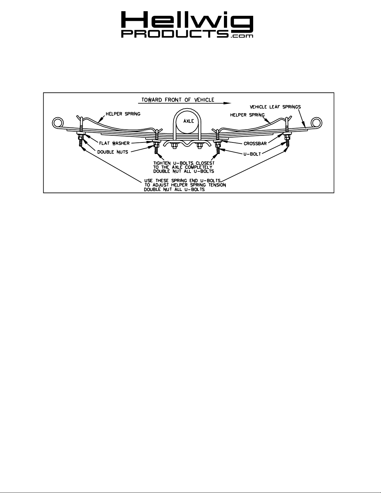
2. Lay the helper springs on top of the vehicle leaf springs, as close as possible to the axle without making contact.
3. Place the U-bolts into the cupped ends of the helper spring so that the U-bolt threads are pointing towards the ground and below
the vehicle leaf springs.
4. Install the crossbar, washers and nuts on the U-bolts closest to the axle first. Tighten these U-bolts completely and double nut.
5. Install the crossbars, washers and nuts on the U-bolts at the ends of the helper springs.
6. Lower the vehicle to the ground and adjust for desired height and tension. To adjust for more load capacity draw the nuts tighter,
loosen to relief capacity. Make certain that double nuts are used after each and every adjustment made. Minimum clearance between the bottom of the U-bolt saddle and the top of the vehicles spring should be no less than 1/8 inch.
7. Bounce the vehicle and check for clearance on all undercarriage components wiring, brake and fuel lines.
8. After one week of driving recheck your installation readjust if necessary. Recheck your installation on a monthly regular basis
thereafter.
ATTENTION INSTALLER: BE SURE THAT THE CUSTOMER RECEIVESTHIS INSTRUCTIONSHEET, ALL IMORTANT
NOTE CARDSAND THEWARRANTY FORM
( R-93 ) 12/16/2011
 Loading...