

Hellwig 5800 User Manual
559-734-7451 800-367-5480 FAX 559-734-7460
INSTALLATION INSTRUCTIONS
Rear Stabilizer Bar 5800
1964-72 GM A-Body Rear Sway Bar
Thank you for purchasing a quality Hellwig Product.
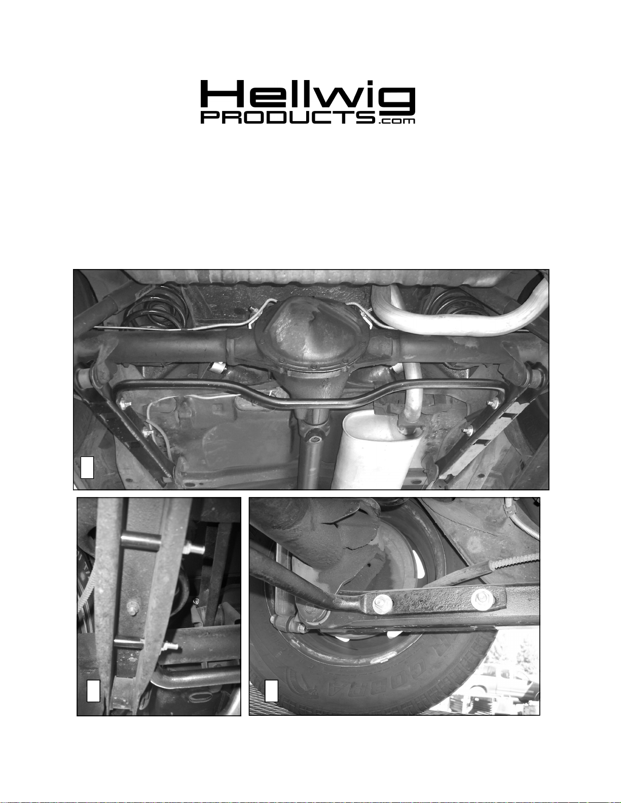
1
2 3
5800(R-5800) 02/03/06
BE SURE THAT THE CUSTOMER RECEIVES THIS INSTRUCTION
559-734-7451 800-367-5480 FAX 559-734-7460
TORQUE TABLE
Bolt Size 3/8”— 35 ft lbs * Bolt Size 7/16”— 45 ft lbs* Bolt Size 1/2”—75 ft lbs *Bolt Size 9/16”— 90 ft lbs
SAFETY: BEFORE BEGINNING INSTALLATION BE SURE TO SET THE PARKING BRAKE AND
CHOCK THE WHEELS.
1. Ensure that the vehicle is secure and stable before working under the vehicle.
2. If vehicle is equipped with factory rear sway bar, remove factory rear sway bar and skip to line 6. Otherwise continue to
line 3.
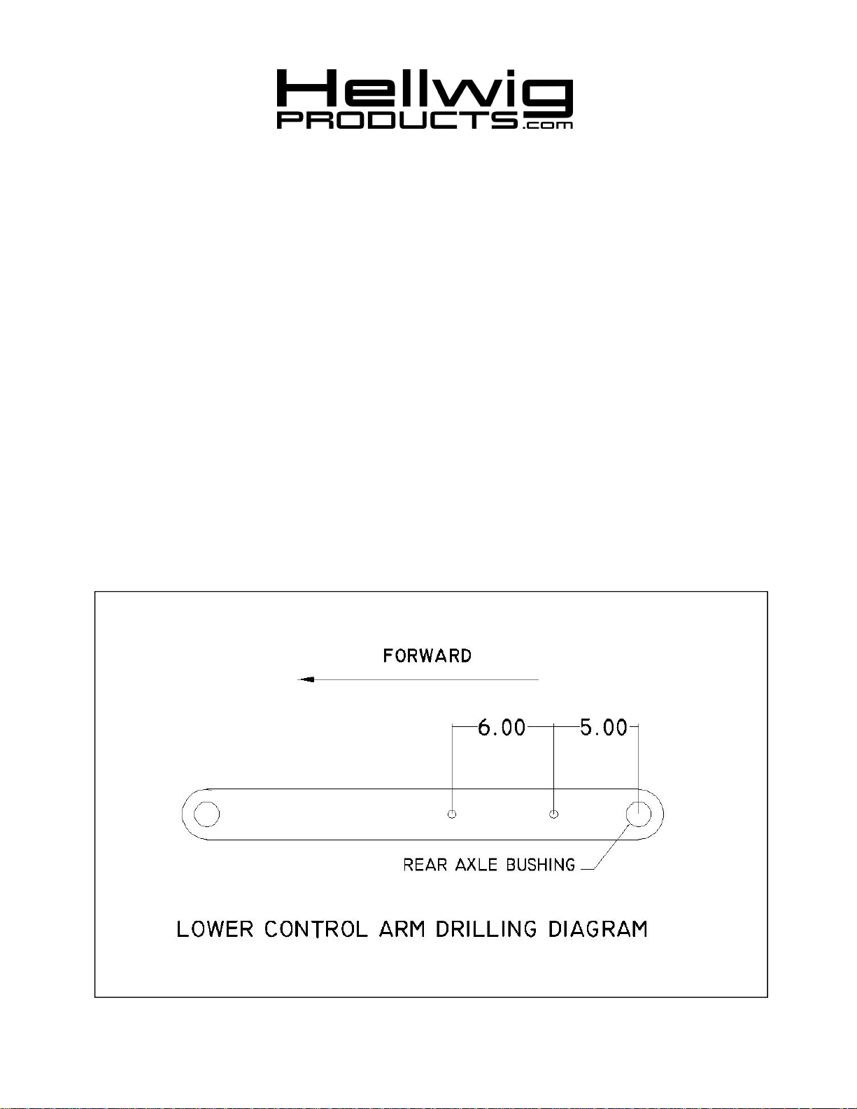
3. Lay out holes in lower control arms as shown in diagram. Locate rear hole 5 inches from center of rear axle bushing. Locate forward hole 6 inches forward of rear hole. Install sway bar between control arms and check fit to marked holes.
4. After checking hole locations for fit, remove sway bar and drill a 1/2” hole through both walls of the control arm in marked
locations. Use a transfer punch or other means to mark holes in outer walls so that holes are square.
5. Install spacers in control arm as shown in photo (2). The spacers may need to be ground down to fit between the walls of the
control arms. They are made slightly long to accommodate variations in the factory control arms. Spacers must be used to
avoid crushing the control arms when the bolts are tightened.
6. Attach sway bar to control arm using supplied hardware.
7. Torque bolts to 35 ft-lb
8. Bounce the vehicle checking for clearance on all under carriage components. Test drive the vehicle and recheck all clearances and the installation alignment. Adjust as needed. Re-check your installation after one week of driving
and periodically on a regular basis.
ATTENTION INSTALLER:
SHEET, ALL IMORTANT NOTE CARDS AND THE WARRANTY FORM
5800(R-5800) 02/03/06
 Loading...